WO2021132347A1 - 有機溶剤回収システム - Google Patents
有機溶剤回収システム Download PDFInfo
- Publication number
- WO2021132347A1 WO2021132347A1 PCT/JP2020/048198 JP2020048198W WO2021132347A1 WO 2021132347 A1 WO2021132347 A1 WO 2021132347A1 JP 2020048198 W JP2020048198 W JP 2020048198W WO 2021132347 A1 WO2021132347 A1 WO 2021132347A1
- Authority
- WO
- WIPO (PCT)
- Prior art keywords
- organic solvent
- desorption
- carrier gas
- suction
- adsorption
- Prior art date
- Legal status (The legal status is an assumption and is not a legal conclusion. Google has not performed a legal analysis and makes no representation as to the accuracy of the status listed.)
- Ceased
Links
Images

Classifications
-
- B—PERFORMING OPERATIONS; TRANSPORTING
- B01—PHYSICAL OR CHEMICAL PROCESSES OR APPARATUS IN GENERAL
- B01D—SEPARATION
- B01D53/00—Separation of gases or vapours; Recovering vapours of volatile solvents from gases; Chemical or biological purification of waste gases, e.g. engine exhaust gases, smoke, fumes, flue gases, aerosols
- B01D53/34—Chemical or biological purification of waste gases
- B01D53/38—Removing components of undefined structure
- B01D53/44—Organic components
-
- B—PERFORMING OPERATIONS; TRANSPORTING
- B01—PHYSICAL OR CHEMICAL PROCESSES OR APPARATUS IN GENERAL
- B01D—SEPARATION
- B01D53/00—Separation of gases or vapours; Recovering vapours of volatile solvents from gases; Chemical or biological purification of waste gases, e.g. engine exhaust gases, smoke, fumes, flue gases, aerosols
- B01D53/02—Separation of gases or vapours; Recovering vapours of volatile solvents from gases; Chemical or biological purification of waste gases, e.g. engine exhaust gases, smoke, fumes, flue gases, aerosols by adsorption, e.g. preparative gas chromatography
- B01D53/04—Separation of gases or vapours; Recovering vapours of volatile solvents from gases; Chemical or biological purification of waste gases, e.g. engine exhaust gases, smoke, fumes, flue gases, aerosols by adsorption, e.g. preparative gas chromatography with stationary adsorbents
- B01D53/0407—Constructional details of adsorbing systems
-
- B—PERFORMING OPERATIONS; TRANSPORTING
- B01—PHYSICAL OR CHEMICAL PROCESSES OR APPARATUS IN GENERAL
- B01D—SEPARATION
- B01D53/00—Separation of gases or vapours; Recovering vapours of volatile solvents from gases; Chemical or biological purification of waste gases, e.g. engine exhaust gases, smoke, fumes, flue gases, aerosols
- B01D53/002—Separation of gases or vapours; Recovering vapours of volatile solvents from gases; Chemical or biological purification of waste gases, e.g. engine exhaust gases, smoke, fumes, flue gases, aerosols by condensation
-
- B—PERFORMING OPERATIONS; TRANSPORTING
- B01—PHYSICAL OR CHEMICAL PROCESSES OR APPARATUS IN GENERAL
- B01D—SEPARATION
- B01D53/00—Separation of gases or vapours; Recovering vapours of volatile solvents from gases; Chemical or biological purification of waste gases, e.g. engine exhaust gases, smoke, fumes, flue gases, aerosols
- B01D53/02—Separation of gases or vapours; Recovering vapours of volatile solvents from gases; Chemical or biological purification of waste gases, e.g. engine exhaust gases, smoke, fumes, flue gases, aerosols by adsorption, e.g. preparative gas chromatography
- B01D53/04—Separation of gases or vapours; Recovering vapours of volatile solvents from gases; Chemical or biological purification of waste gases, e.g. engine exhaust gases, smoke, fumes, flue gases, aerosols by adsorption, e.g. preparative gas chromatography with stationary adsorbents
- B01D53/0407—Constructional details of adsorbing systems
- B01D53/0438—Cooling or heating systems
-
- B—PERFORMING OPERATIONS; TRANSPORTING
- B01—PHYSICAL OR CHEMICAL PROCESSES OR APPARATUS IN GENERAL
- B01D—SEPARATION
- B01D53/00—Separation of gases or vapours; Recovering vapours of volatile solvents from gases; Chemical or biological purification of waste gases, e.g. engine exhaust gases, smoke, fumes, flue gases, aerosols
- B01D53/34—Chemical or biological purification of waste gases
- B01D53/74—General processes for purification of waste gases; Apparatus or devices specially adapted therefor
- B01D53/81—Solid phase processes
- B01D53/82—Solid phase processes with stationary reactants
-
- B—PERFORMING OPERATIONS; TRANSPORTING
- B01—PHYSICAL OR CHEMICAL PROCESSES OR APPARATUS IN GENERAL
- B01D—SEPARATION
- B01D53/00—Separation of gases or vapours; Recovering vapours of volatile solvents from gases; Chemical or biological purification of waste gases, e.g. engine exhaust gases, smoke, fumes, flue gases, aerosols
- B01D53/34—Chemical or biological purification of waste gases
- B01D53/96—Regeneration, reactivation or recycling of reactants
-
- B—PERFORMING OPERATIONS; TRANSPORTING
- B01—PHYSICAL OR CHEMICAL PROCESSES OR APPARATUS IN GENERAL
- B01D—SEPARATION
- B01D2253/00—Adsorbents used in seperation treatment of gases and vapours
- B01D2253/10—Inorganic adsorbents
- B01D2253/102—Carbon
-
- B—PERFORMING OPERATIONS; TRANSPORTING
- B01—PHYSICAL OR CHEMICAL PROCESSES OR APPARATUS IN GENERAL
- B01D—SEPARATION
- B01D2256/00—Main component in the product gas stream after treatment
- B01D2256/24—Hydrocarbons
-
- B—PERFORMING OPERATIONS; TRANSPORTING
- B01—PHYSICAL OR CHEMICAL PROCESSES OR APPARATUS IN GENERAL
- B01D—SEPARATION
- B01D2257/00—Components to be removed
- B01D2257/70—Organic compounds not provided for in groups B01D2257/00 - B01D2257/602
- B01D2257/704—Solvents not covered by groups B01D2257/702 - B01D2257/7027
-
- B—PERFORMING OPERATIONS; TRANSPORTING
- B01—PHYSICAL OR CHEMICAL PROCESSES OR APPARATUS IN GENERAL
- B01D—SEPARATION
- B01D2259/00—Type of treatment
- B01D2259/40—Further details for adsorption processes and devices
- B01D2259/40083—Regeneration of adsorbents in processes other than pressure or temperature swing adsorption
- B01D2259/40086—Regeneration of adsorbents in processes other than pressure or temperature swing adsorption by using a purge gas
-
- B—PERFORMING OPERATIONS; TRANSPORTING
- B01—PHYSICAL OR CHEMICAL PROCESSES OR APPARATUS IN GENERAL
- B01D—SEPARATION
- B01D2259/00—Type of treatment
- B01D2259/40—Further details for adsorption processes and devices
- B01D2259/40083—Regeneration of adsorbents in processes other than pressure or temperature swing adsorption
- B01D2259/40088—Regeneration of adsorbents in processes other than pressure or temperature swing adsorption by heating
Definitions
- the present invention relates to an organic solvent recovery system that separates an organic solvent from a gas to be treated containing an organic solvent and recovers the separated organic solvent using a carrier gas.
- an adsorbent is used to adsorb and desorb an organic solvent on a gas to be treated containing an organic solvent, and the organic solvent is moved from the gas to be treated to a carrier gas to purify the gas to be treated.
- An organic solvent-containing gas treatment system that enables recovery of an organic solvent is known.
- This type of organic solvent recovery system generally includes an adsorption / desorption treatment device that alternately contacts a gas to be treated containing an organic solvent and a carrier gas in a high temperature state with an adsorbent in a timely manner, and discharges from the suction / desorption treatment device. It is equipped with a condensing recovery device that condenses and recovers the organic solvent by cooling the carrier gas to be produced.
- Patent Document 1 discloses an organic solvent-containing gas treatment system using water vapor as a carrier gas.
- Patent Document 2 states that the organic solvent was heated to a high temperature as a carrier gas.
- An organic solvent recovery system using an inert gas is disclosed.
- Patent Document 3 an inert gas heated to a high temperature is used as a carrier gas, and the inert gas is circulated and used in the organic solvent recovery system to reduce the amount of the inert gas used. The recovery system is disclosed.
- the carrier gas discharged from the condensing recovery device contains an uncondensed organic solvent. Therefore, in the case of a configuration in which the carrier gas is circulated and returned to the adsorption / desorption treatment device, the regeneration of the adsorbent becomes insufficient, and there is a natural limit to the improvement of the purification capacity for the gas to be treated and the recovery efficiency of the organic solvent. There was a problem.
- Patent Document 3 by providing a second adsorption / desorption treatment device for adsorbing and removing the organic solvent from the carrier gas containing the uncondensed organic solvent discharged from the condensation recovery device, the purification ability for the gas to be treated and the organic solvent are provided. The recovery efficiency of the solvent is improved.
- the carrier gas is circulated by means of a second adsorption / desorption processing device filled with the second adsorption / desorption element, a temperature adjusting means for adjusting the carrier gas to a high temperature state in order to desorb the organic solvent from the second adsorption / desorption element, and the like. It is necessary to provide it on the route, and there is a problem that the system configuration becomes complicated and large.
- the present invention has been made to solve the above-mentioned problems, the running cost can be suppressed, the purification capacity of the gas to be treated and the recovery efficiency of the organic solvent are improved, and the system configuration can be simplified and downsized. It is an object of the present invention to provide a designed organic solvent recovery system.
- the present invention has the following configuration.
- An organic solvent recovery system that separates and recovers an organic solvent from a gas to be treated containing an organic solvent, and has a circulation path for circulating and passing a carrier gas, and an adsorption / desorption element provided on the circulation path.
- An adsorption / desorption treatment device that alternately performs adsorption of the organic solvent by introduction of the gas to be treated and desorption of the organic solvent by introduction of the carrier gas, and a downstream side of the suction / desorption treatment device on the circulation path.
- a condensing recovery device provided in the above which is provided with a cooling unit for cooling the carrier gas discharged from the suction / desorption treatment device, and the cooling unit condenses the organic solvent in the carrier gas and recovers it as a condensate.
- the suction / desorption processing apparatus includes a cooling inlet path for introducing the low-temperature carrier gas discharged from the vehicle into the suction / desorption element without passing through the heating unit, and the suction / desorption processing apparatus introduces the gas to be processed into the adsorption element. Later, the carrier gas heated by the heating unit was introduced, then the carrier gas in a low temperature state was introduced from the cooling inlet path, and then the gas to be treated was introduced again.
- An organic solvent recovery system characterized by having a melting portion for temporarily heating and thawing a component frozen by cooling the carrier gas.
- the carrier gas can be cooled at a lower temperature than the conventional system, the efficiency of condensation and recovery of the organic solvent can be improved. Further, as a result, the concentration of the organic solvent in the carrier gas discharged from the condensing recovery device can be reduced, and the desorption efficiency by the carrier gas in the adsorption treatment device is increased. Therefore, a second suction / desorption is separately performed on the downstream side of the condensing recovery device. There is no need to provide a processing device.
- a heated carrier gas is introduced into the suction / desorption element to perform desorption, and then the suction / desorption element is cooled by introducing the carrier gas from the cooling inlet path. After that, adsorption is performed again by the suction / desorption element. Therefore, since the suction / desorption element heated by the introduction of the carrier gas can be cooled, the organic solvent in the gas to be treated can be efficiently adsorbed in the adsorption in the suction / desorption element, and the purification ability for the gas to be treated is improved.
- the organic solvent recovery system of the present invention can reduce the running cost, improve the purification capacity of the gas to be treated and the recovery efficiency of the organic solvent, and further simplify and downsize the system configuration. it can.
- the condensation recovery device has a refrigerant heat medium supply unit that selectively supplies a refrigerant and a heat medium, and the cooling unit and the melting unit are configured to be the same as a cooling / melting unit, and the cooling / melting unit is configured as a cooling / melting unit.
- the organic according to 1 above wherein the refrigerant is supplied from the refrigerant heat medium supply unit and functions as the cooling unit, and the heat medium is supplied from the refrigerant heat medium supply unit and functions as the melting unit. Refrigerant recovery system.
- a heat medium can be temporarily supplied to the cooling / thawing portion as a cooling source to efficiently heat the frozen component, so that the frozen component can be thawed in a short time.
- the condenser heat medium supply unit includes a static pressure difference measuring unit that measures the difference in static pressure between the inlet side and the outlet side of the carrier gas in the condensation recovery device, and the refrigerant heat medium supply unit is the difference in static pressure measured by the static pressure measuring unit.
- the problem of gas flow due to the adhesion of frozen components can be detected from the measurement results of the static pressure difference measuring unit, and by switching to heat medium supply, the frozen components can be automatically heated and thawed. it can.
- a vapor pressure measuring unit for measuring the vapor pressure of the organic solvent contained in the carrier gas discharged from the condensation recovery device is provided so that the vapor pressure of the organic solvent measured by the vapor pressure measuring unit is equal to or less than a predetermined value.
- the organic solvent recovery system according to any one of 1 to 3 above, further comprising a temperature control unit for adjusting the temperature of the cooling unit.
- the concentration of the organic solvent in the discharged carrier gas can be kept below a certain level, and the organic solvent adsorbed on the adsorption / desorption element can be efficiently desorbed. ..
- the carrier gas into the condensation recovery device through the cooling inlet path during melting, the melted components can be placed on the carrier gas and efficiently liquefied and recovered.
- the suction / desorption treatment apparatus is characterized in that the suction / desorption element is purged after the adsorption and before the desorption, and the melting portion is melted during the purge treatment period.
- the organic solvent recovery system according to any one of 5 to 5.
- the suction / desorption process is not temporarily stopped and the system is not melted, so that the system can be operated efficiently.
- the component frozen by cooling the carrier gas is temporarily heated by the melting portion to be thawed, the problem of gas flow due to the adhesion of the frozen component can be solved. Therefore, since the carrier gas can be cooled at a lower temperature than the conventional system, the efficiency of condensation and recovery of the organic solvent can be improved. Further, as a result, the concentration of the organic solvent in the carrier gas discharged from the condensing recovery device can be reduced, and the desorption efficiency by the carrier gas in the adsorption treatment device is increased. There is no need to provide a processing device.
- the organic solvent recovery system of the present invention can reduce the running cost, improve the purification capacity of the gas to be treated and the recovery efficiency of the organic solvent, and further simplify and downsize the system configuration. Can be done.
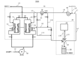
- the device 20 and the circulation blower 40 are provided. Further, it is provided with a gas blower 50 to be treated, which supplies the gas to be treated to the suction / desorption treatment device 10.
- the carrier gas various types of gases such as steam, heated air, and an inert gas heated to a high temperature can be used.
- the organic solvent recovery system 100A can be configured more simply.
- the circulation path L1 includes piping lines L4 to L7, a cooling inlet path L12, and a cooling outlet path L13 shown in the figure.
- the circulation blower 40 is a blowing means for passing the carrier gas through the circulation path L1
- the gas to be treated blower 50 is a blowing means for introducing the gas to be treated into the suction / desorption treatment device 10.
- the suction / desorption processing device 10 includes a suction / desorption tank A11, a suction / desorption tank B12, and a heater 30.
- the adsorption / desorption tank A11 is filled with an adsorption / desorption element A13 that adsorbs and desorbs an organic solvent
- the adsorption / desorption tank B12 is filled with an adsorption / desorption element B14 that adsorbs and desorbs an organic solvent.
- two suction / desorption tanks are provided, but the number of suction / desorption tanks may be one or three or more.
- the heater 30 adjusts (heats) the temperature of the carrier gas supplied to the suction / desorption tank A11 or the suction / desorption tank B12 to a high temperature state. More specifically, the heater 30 adjusts the temperature of the carrier gas discharged from the condensation recovery device 20 and passing through the circulation blower 40 to a high temperature state, and supplies the carrier gas to the suction / desorption tank A11 or the suction / desorption tank B12. Here, the heater 30 adjusts the temperature of the carrier gas introduced into the suction / desorption tank A11 and the suction / desorption tank B12 so that the suction / desorption element A13 and the suction / desorption element B14 are maintained at a predetermined desorption temperature.
- the adsorption / desorption element A13 and the adsorption / desorption element B14 adsorb the organic solvent and a part of the water contained in the gas to be treated by bringing them into contact with the gas to be treated. Therefore, in the suction / desorption treatment device 10, when the gas to be treated is supplied to the suction / desorption tank A11 or the suction / desorption tank B12, the organic solvent and a trace amount of water are adsorbed by the suction / desorption element A13 or the suction / desorption element B14 from the gas to be treated. The organic solvent is removed to purify the gas to be treated, and the gas is discharged as a clean gas from the adsorption / desorption tank A11 or the adsorption / desorption tank B12.
- the adsorption / desorption element A13 and the adsorption / desorption element B14 desorb the adsorbed organic solvent and trace moisture by contacting the carrier gas in a high temperature state. Therefore, in the suction / desorption treatment device 10, when the carrier gas in a high temperature state is supplied to the suction / desorption tank A11 or the suction / desorption tank B12, the organic solvent and a trace amount of water are desorbed from the suction / desorption element A13 or the suction / desorption element B14. A carrier gas containing an organic solvent and water is discharged from the suction / desorption tank A11 or the suction / desorption tank B12.
- the adsorption / desorption element A13 and the adsorption / desorption element B14 are composed of an adsorbent containing any one of granular activated carbon, activated carbon fiber, zeolite, silica gel, a porous polymer, and a metal-organic framework.
- activated carbon or zeolite in the form of granules, powder, honeycomb or the like is used, but more preferably, activated carbon fiber is used. Since the activated carbon fiber has a fibrous structure having micropores on its surface, it has high contact efficiency with gas and realizes higher adsorption efficiency than other adsorbents.
- activated carbon fiber has higher adsorption selectivity for organic solvents than activated carbon in the form of granules, powder, honeycomb, etc., it hardly adsorbs water contained in the gas to be treated. Therefore, the amount of water contained in the carrier gas discharged from the adsorption / desorption tank A11 or the adsorption / desorption tank B12 of the adsorption / desorption treatment device 10 becomes extremely small, and the organic solvent recovery system 100A can be configured more simply, and the organic solvent can be constructed. The recovery system can be miniaturized. When an adsorption / desorption element having low adsorption selectivity for an organic solvent is used, a large amount of water contained in the gas to be treated is adsorbed.
- the amount of water contained in the carrier gas discharged from the suction / desorption tank A11 and the suction / desorption tank B12 of the suction / desorption treatment device 10 also becomes large, and the wastewater containing the organic solvent is discharged from the organic solvent recovery system 100A. , Separate wastewater treatment is required.
- Piping lines L2 and L3 are connected to the suction / desorption processing device 10, respectively.
- the piping line L2 is a piping line for supplying the gas to be treated containing an organic solvent and moisture to the suction / desorption tank A11 or the suction / desorption tank B12 via the gas blower 50 to be treated.
- the connection / non-connection state of the piping line L2 to the suction / detachment tank A11 is switched by the valve V1
- the connection / non-connection state to the suction / detachment tank B12 is switched by the valve V3.
- the piping line L3 is a piping line for discharging clean gas from the suction / desorption tank A11 or the suction / desorption tank B12.
- the valve V2 switches the connection / non-connection state of the piping line L3 to the suction / detachment tank A11
- the valve V4 switches the connection / non-connection state to the suction / detachment tank
- piping lines L5 and L6 are connected to the suction / desorption processing device 10, respectively.
- the piping line L5 is a piping line for supplying the carrier gas to the suction / desorption tank A11 or the suction / desorption tank B12 via the heater 30, or for discharging the carrier gas from the suction / desorption tank A11 or the suction / desorption tank B12. Is.
- the connection / non-connection state of the piping line L5 to the suction / detachment tank A11 is switched by the valve V5, and the connection / non-connection state to the suction / detachment tank B12 is switched by the valve V7.
- the piping line L6 is used to discharge the carrier gas from the suction / desorption tank A11 or the suction / desorption tank B12, or to supply the carrier gas to the suction / desorption tank A11 or the suction / desorption tank B12 via the cooling inlet path L12. It is a piping line.
- the connection / non-connection state of the piping line L6 to the suction / detachment tank A11 is switched by the valve V6, and the connection / non-connection state to the suction / detachment tank B12 is switched by V8.
- the condensate recovery device 20 includes a condenser (condenser) 21, a recovery tank 22, and a refrigerant / heat medium supply unit 23.
- the condenser 21 condenses the organic solvent and trace moisture contained in the carrier gas by adjusting the temperature of the carrier gas in a high temperature state discharged from the suction / desorption tank A11 or the suction / desorption tank B12 to a low temperature state. Is. Specifically, the capacitor 21 liquefies an organic solvent and a trace amount of water by indirectly cooling the carrier gas with a refrigerant such as antifreeze.
- the recovery tank 22 stores the organic solvent liquefied by the condenser 21 and a trace amount of water as a condensate.
- the recovery tank 22 and the refrigerant / heat medium supply unit 23 may be provided outside the condensation recovery device 20.
- the refrigerant / heat medium supply unit 23 is for supplying the refrigerant or heat medium to the capacitor 21 alternately in time. Therefore, in the condensation recovery device 20, the refrigerant is supplied from the refrigerant / heat medium supply unit 23, and the carrier gas containing the organic solvent and trace moisture discharged from the adsorption / desorption treatment device 10 is indirectly cooled by the condenser 21 to be cooled at a low temperature. Condensation processing (condenser supply) that condenses the organic solvent and trace moisture by adjusting the temperature to the above state, and the moisture and organic solvent (freezing) solidified by the condenser 21 by supplying the heat medium from the refrigerant / heat medium supply unit 23.
- Condensation processing condenses the organic solvent and trace moisture by adjusting the temperature to the above state, and the moisture and organic solvent (freezing) solidified by the condenser 21 by supplying the heat medium from the refrigerant / heat medium supply unit 23.
- a melting process (heat medium supply) is carried out in which the resulting components are indirectly heated and melted.
- a heat medium can be temporarily supplied to the capacitor as a cooling source to efficiently heat the frozen component, so that the frozen component can be thawed in a short time.
- the refrigerant and heat medium any one of water, ethanol, ethylene glycol, propylene glycol, chlorofluorocarbons, hydrochlorofluorocarbons, hydrofluorocarbons, or a mixture thereof can be used, but is particularly limited. is not it.
- the heat medium means a medium having a temperature higher than that of the refrigerant.
- the refrigerant and heat medium are preferably liquids, and if the refrigerant and heat medium are respectively stored in a tank, the switching from the condensation process to the melting process and the switching from the melting process to the condensation process can be lubricated. It can be carried out in a short time.
- Piping lines L6 and L7 are connected to the condensate recovery device 20, respectively.
- the piping line L6 is a piping line for supplying the carrier gas discharged from the suction / desorption processing device 10 to the condenser 21.
- the piping line L7 is a piping line for discharging the carrier gas from the condenser 21.
- the piping line L9 is connected to the capacitor 21.
- the piping line L9 is a piping line for introducing the organic solvent and trace amounts of water condensed by the condenser 21 into the recovery tank 22.
- piping lines L10 and L11 are connected to the capacitor 21, respectively.
- the piping line L10 is a piping line for supplying the refrigerant or heat medium from the refrigerant / heat medium supply unit 23 to the capacitor 21.
- the piping line L11 is a piping line that discharges a refrigerant or a heat medium from the capacitor 21 to the outside.
- the piping line L11 is connected to the refrigerant / heat medium supply unit 23, and the refrigerant or heat medium is circulated and used. By circulating and using the refrigerant or heat medium, the amount of heat can be recovered, and the condensation recovery device 20 can be operated with energy saving.
- a cooling inlet path L12 connecting the branch point provided in the piping line L4 and the branch point provided in the piping line L6 is provided on the circulation path L1.
- the connection / non-connection state of the piping lines L4 and L6 is switched by the valve V9 in the cooling inlet path L12.
- the branch point between the cooling inlet path L12 and the piping line L4 is located on the downstream side of the condensing recovery device 20 and the upstream side of the heater 30, and the branch point between the cooling inlet path L12 and the piping line L6 is subjected to suction / desorption processing. It is located on the downstream side of the device 10 and on the upstream side of the condensation recovery device 20.
- a cooling outlet path L13 connecting the branch point provided in the piping line L5 and the branch point provided in the piping line L6 is provided on the circulation path L1.
- the connection / non-connection state of the piping lines L5 and L6 is switched by the valve V11 in the cooling outlet path L13.
- the branch point between the cooling inlet path L13 and the piping line L5 is located on the downstream side of the heater 30 and the upstream side of the suction / desorption processing device 10, and the branch point between the cooling inlet path L13 and the piping line L6 is located. It is located on the downstream side of the branch point between the cooling inlet path L12 and the piping line L6 and on the upstream side of the condensation recovery device 20.
- a valve V10 is provided between the branch point between the piping line L4 and the cooling inlet path L12 and the branch point between the piping line L5 and the cooling outlet path L13, and the valve V10 provides the piping line L4 and the cooling inlet path.
- the connection / non-connection state between the branch point with L12 and the branch point between the piping line L5 and the cooling outlet path L13 is switched.
- a valve V12 is provided between the branch point between the piping line L6 and the cooling inlet path L12 and the branch point between the piping line L6 and the cooling outlet path L13, and the valve V12 provides the piping line L6 and the cooling inlet path.
- the connection / non-connection state between the branch point with L12 and the branch point between the piping line L6 and the cooling outlet path L13 is switched.
- the carrier gas is alternately supplied to either the suction / desorption tank A11 or the suction / desorption tank B12 in either a high temperature state or a low temperature state. .. More specifically, when the valves V10 and V12 are open and the valves V9 and V11 are closed, the carrier gas is supplied to either the suction / desorption tank A11 or the suction / desorption tank B12 at a high temperature via the heater 30.
- the carrier gas is supplied to either the suction / desorption tank A11 or the suction / desorption tank B12 at a low temperature via the cooling inlet path L12. ..
- the suction / desorption tank A11 and the suction / desorption tank B12 by operating the opening and closing of the valves V1 to V8 described above, the gas to be treated, the carrier gas in the high temperature state, and the low temperature state can be obtained.
- a certain carrier gas is supplied in order in time.
- the suction / desorption tank A11 and the suction / desorption tank B12 function as the adsorption tank and the desorption tank in order in time, and the organic solvent and the trace amount of water are in a high temperature state from the gas to be treated. Move to gas.
- the suction / desorption tank B12 functions as a desorption tank
- the suction / desorption tank A11 functions as a desorption tank
- the suction / desorption tank B12 functions as a suction tank.
- the carrier gas heated by the heater 30 and the carrier gas from the cooling inlet path come into contact with the suction / desorption element A13 or the suction / desorption element B14 in the countercurrent direction, thereby causing the suction / desorption element A13 or the suction / desorption element.
- Desorption by heating B14 and cooling of the suction / desorption element A13 or the suction / desorption element B14 can be effectively performed.
- FIG. 2 is a time chart showing a state of temporal switching between the adsorption process and the desorption process using the adsorption / desorption element A13 and the desorption element B14 in the organic solvent recovery system 100A shown in FIG.
- FIG. 2 the details of the treatment of the gas to be treated using the organic solvent recovery system 100A in the present embodiment will be described by taking an inert gas as the carrier gas as an example.
- the organic solvent recovery system 100A can continuously process the gas to be treated by repeating the cycle with one cycle shown in FIG. 2 as a unit period.
- the adsorption treatment is carried out in the suction / desorption tank A11 filled with the suction / desorption element A13.
- a purging process between times t0 and t1 shown in FIG. 2) for replacing the inside of the suction / desorption tank B12 with an inert gas is performed.
- a desorption treatment between times t1 and t2 shown in FIG. 2 is carried out, and then a cooling treatment (time t2 to t3 shown in FIG.
- the inert gas and carrier gas used in the purging process are the same.
- the downstream side of the suction / desorption tank B12 during the purging process is connected to the upstream side of the gas blower 40 to be treated, and the gas to be treated (the gas remaining in the suction / desorption tank B12) that is replaced with the inert gas and discharged is adsorbed. It is preferable to pipe the suction / desorption tank A11 to be treated so that the gas to be treated is supplied together with the gas to be treated. This is because the recovery rate of the organic solvent can be increased by piping so as to be subjected to the adsorption treatment again.
- the downstream side of the suction / desorption tank during the barge treatment is configured to be connected to the upstream side of the gas blower 40 to be processed and not connected to the condenser 21 side. (Not shown).
- This connection / disconnection state can be switched with a valve.
- the adsorption treatment is carried out in the suction / desorption tank B12 filled with the suction / desorption element B14.
- a purging process between times t3 and t4 shown in FIG. 2) for replacing the inside of the suction / desorption tank A11 with an inert gas is performed.
- a desorption treatment between times t4 and t5 shown in FIG. 2 is carried out, and then a cooling treatment of the suction and desorption element A13 (time t5 to t6 shown in FIG. 2) is carried out.
- the refrigerant is supplied from the refrigerant / heat medium supply unit 23, and the carrier gas containing the organic solvent and trace moisture discharged from the absorption / desorption processing device 10 is indirectly cooled by the condenser 21 to cool the temperature to a low temperature state.
- a condensing process (between times t0 and t2 shown in FIG. 2) is performed to adjust and condense the organic solvent, and the organic solvent and a trace amount of water are recovered.
- the condensation recovery device 20 includes a vapor pressure measuring unit (not shown) for measuring the vapor pressure of the organic solvent contained in the carrier gas discharged from the condenser 21, and the vapor of the organic solvent measured by the vapor pressure measuring unit. It may have a temperature control unit (not shown) that controls the temperature of the condenser 21 so that the pressure is equal to or lower than a predetermined value. By adjusting the temperature of the condenser, the concentration of the organic solvent in the discharged carrier gas can be kept below a certain level, and the organic solvent adsorbed on the adsorption / desorption element A13 and the adsorption / desorption element B14 can be efficiently desorbed. ..
- the temperature adjustment of the carrier gas can be controlled by the amount of the refrigerant from the refrigerant / heat medium supply unit 23 or the temperature of the refrigerant. Specifically, it has the relationship between the temperature and the vapor pressure as data, and adjusts the temperature of the carrier gas with the refrigerant so that the desired vapor pressure is obtained.
- the relationship between temperature and vapor pressure differs depending on the type of organic solvent, but can be confirmed in the literature.
- the vapor pressure of the organic solvent can be measured by a VOC densitometer, gas chromatography or the like.
- the condensation recovery device 20 for example, the condenser 21 and the adsorption / desorption treatment device 10 It is not necessary to install an adsorption / desorption element for adsorbing and removing the organic solvent in the carrier gas between the two, and the organic solvent recovery system 100A can be made simple and miniaturized.
- the carrier gas is introduced into the suction / desorption tank B12 via the cooling inlet path L12 to cool the suction / desorption element B14.
- the adsorption / desorption element B14 is insufficiently cooled, it is difficult for the organic solvent to be sufficiently adsorbed because the adsorption / desorption element B14 has a high temperature in the adsorption process of the adsorption / desorption tank B12 (time t4 to t6 shown in FIG. 2). Performance degradation occurs as a system.
- the carry gas is introduced into the suction / desorption tank A11 via the cooling inlet path L12.
- the carrier gas discharged from the suction / desorption tank B12 merges with the carrier gas flowing through the piping line L6 via the cooling outlet path L13, and enters the condensation recovery device 20. Be supplied.
- the carrier gas discharged from the suction / desorption tank B12 contains a large amount of an organic solvent, and the organic solvent is recovered by the condensation recovery device 20.
- the carry gas discharged from the suction / desorption tank A11 merges with the carrier gas flowing through the piping line L6 via the cooling outlet path L13. It is supplied to the condensation recovery device 20.
- the condensation recovery device 20 adjusts the temperature of the carrier gas so that the vapor pressure of the organic solvent contained in the carrier gas discharged from the condenser 21 is equal to or less than a predetermined value, the carrier gas is reduced to 0 depending on the type of the organic solvent. It is necessary to adjust the temperature below °C. Therefore, the organic solvent and trace moisture contained in the carrier gas solidify in the condenser 21, the flow path of the carrier gas is blocked, the ventilation resistance of the condenser 21 increases, and the carrier gas cannot flow.
- the refrigerant / heat medium supply unit 23 by switching from the supply of the refrigerant to the supply of the heat medium, the organic solvent solidified and the trace amount of water are indirectly heated and melted so that the flow path in the condenser 21 is not obstructed. The process (between times t2 and t4 shown in FIG. 2) is carried out. The melted organic solvent and trace water are discharged to the recovery tank 22 through the piping line L9.
- the carrier gas to the condenser 21 via the cooling inlet path L12 with the valves V9 and V12 open and the valves V10 and V11 closed. This is because by supplying the carrier gas to the condenser 21 during the melting process, the melted organic solvent and trace moisture can easily move to the piping line L9 and can be efficiently liquefied and recovered. It is preferable to supply the carrier gas to the capacitor 21 to perform the melting treatment during the purging treatment in which the suction / desorption element A13 or the suction / desorption element B14 does not perform the desorption treatment.
- the suction / desorption tank 12 during the purging process is not connected to the condenser 21, and instead is connected to the upstream of the gas blower 50 to be processed. Therefore, during the purging process.
- the gas to be treated (the gas remaining in the suction / desorption tank B12) that is replaced with the inert gas and discharged is not supplied to the condenser 21.
- the process is continued until the organic solvent and the trace amount of water in the condenser 21 are completely melted, and when the melting of the organic solvent and the trace amount of water is completed, the refrigerant / heat medium supply unit 23 starts supplying the heat medium. Switch to refrigerant supply.
- the condenser 21 indirectly cools the carrier gas, adjusts the temperature to a low temperature state, and re-executes the condensation process (between times t4 and t6 shown in FIG. 2) to condense the organic solvent and trace water.
- the melting process is performed between the times t2 and t4 as an example, but the melting process of the capacitor 21 does not have to be performed every cycle. It may be done regularly or irregularly. Further, as shown in FIG. 2, it is not necessary to perform only between the cooling treatment of the suction / desorption element B14 and the purging treatment of the suction / desorption element A13, and the cooling treatment of the suction / desorption element A13 to the purging treatment of the suction / desorption element B14. You may go between.
- the configuration may be such that the condensation process is performed with a capacitor. Further, in this case, the capacitor to be subjected to the melting process and the capacitor to be subjected to the condensation process may be switched by operating the valve, but the configuration is not particularly limited.
- a method of supplying a heating gas into the condenser 21 to heat the solidified organic solvent and trace components can be considered.
- this method requires a huge amount of energy because the entire inside of the capacitor 21 needs to be heated to a high temperature, and it takes a long time to completely melt.
- melting is performed by applying a means for heating only the coil in the capacitor 21 to a high temperature with a heat medium as in the present embodiment. The energy required for processing can be minimized, and melting can be completed in a short time. Therefore, it is possible to establish a system with only one capacitor.
- a static pressure difference measuring unit (not shown) for measuring the difference between the static pressure at the inlet of the carrier gas 21 and the static pressure at the outlet of the condenser 21 is provided, and the difference in static pressure reaches a predetermined value or more. If the condensing process is switched to the melting process at that time, an increase in the ventilation resistance of the capacitor 21 can be prevented at all times. From the measurement result of the static pressure difference measurement unit, the problem of gas flow due to the adhesion of frozen components can be detected, and by switching to the melting process (heat medium supply), the frozen components can be automatically heated and thawed. ..
- the "predetermined value” is determined by setting the pressure loss (differential pressure) of the condenser 21 to such an extent that the air volume of the circulating blower 40 does not significantly decrease as a limit value.
- the correlation between the pressure loss of the condenser 21 and the decrease in air volume of the circulating blower 40 is determined by the discharge pressure capacity of the circulating blower 40.
- the concentration of the organic solvent and the concentration of water contained in the gas to be treated can be grasped in advance, the data is stored as data, and the refrigerant / heat medium supply unit 23 condenses and melts at regular time intervals. The process may be switched.
- the moisture contained in the gas to be treated is hardly adsorbed, so that the moisture contained in the carrier gas supplied to the condenser 21 is extremely small. Become. Therefore, the amount of water that solidifies in the capacitor 21 is extremely small, the frequency with which the capacitor 21 performs the melting process is significantly reduced, the energy required for the melting process can be reduced, and the organic solvent recovery system 100A has a simpler configuration. can do.
- the components frozen in the condensation process for cooling the carrier gas are temporarily heated and thawed by the condenser 21 provided with the heat medium. Therefore, the problem of gas flow due to the adhesion of frozen components can be solved. Therefore, since the carrier gas can be cooled at a lower temperature than the conventional system, the efficiency of condensation and recovery of the organic solvent can be improved. Further, as a result, the concentration of the organic solvent in the carrier gas discharged from the condensation recovery device 20 can be reduced, and the desorption efficiency by the carrier gas in the adsorption treatment device is increased. It is not necessary to provide an adsorption / desorption processing device.
- the heated carrier gas is introduced into the suction / desorption element A13 or the suction / desorption element B14 to perform desorption.
- the suction / desorption element A13 or the suction / desorption element B14 is cooled by introducing the carrier gas from the cooling inlet path L12, and then the gas to be treated is introduced again to be adsorbed by the suction / desorption element A13 or the suction / desorption element B14.
- the heated suction / desorption element A13 or the suction / desorption element B14 can be cooled by introducing the carrier gas from the cooling inlet path L12. Therefore, in the adsorption by the suction / desorption element A13 or the suction / desorption element B14, the organic in the gas to be treated is organic.
- the solvent can be adsorbed efficiently, and the purification capacity for the gas to be treated is improved.
- the organic solvent recovery system 100A the running cost can be reduced, the purification capacity for the gas to be treated and the recovery efficiency of the organic solvent can be improved, and the system has a higher performance and a simpler configuration than the conventional system. Can be.
- the organic solvent recovery system 100A of the present embodiment is excellent in economy because the carrier gas can be used repeatedly by constructing a circulation path. Therefore, when an inert gas typified by nitrogen gas or the like is used as the carrier gas, the effect of suppressing the running cost can be obtained.
- the present invention can be effectively used, for example, in a system for treating a gas to be treated containing an organic solvent discharged from a factory or a building.
- Adsorption / desorption processing device 11 Adsorption / desorption tank A 12 Desorption tank B 13 Adsorption element A 14 Adsorption element B 20 Condensation recovery device 21 Capacitor (melting part, cooling part, cooling and melting part) 22 Recovery tank 23 Refrigerant / heat medium supply unit (refrigerant heat medium supply unit) 30 heater (heating part) 40 Circulation blower 50 Gas blower to be treated 100A Organic solvent recovery system L1 Circulation path L2 to L11 Piping line L12 Cooling inlet path L13 Cooling outlet path V1 to V12 Valve
Landscapes
- Chemical & Material Sciences (AREA)
- Engineering & Computer Science (AREA)
- Analytical Chemistry (AREA)
- General Chemical & Material Sciences (AREA)
- Oil, Petroleum & Natural Gas (AREA)
- Chemical Kinetics & Catalysis (AREA)
- Environmental & Geological Engineering (AREA)
- Health & Medical Sciences (AREA)
- Biomedical Technology (AREA)
- Life Sciences & Earth Sciences (AREA)
- Sustainable Development (AREA)
- Separation Of Gases By Adsorption (AREA)
- Treating Waste Gases (AREA)
Priority Applications (4)
| Application Number | Priority Date | Filing Date | Title |
|---|---|---|---|
| CN202080090012.1A CN114867542B (zh) | 2019-12-25 | 2020-12-23 | 有机溶剂回收系统 |
| KR1020227024747A KR20220113523A (ko) | 2019-12-25 | 2020-12-23 | 유기 용제 회수 시스템 |
| JP2021567543A JP7771754B2 (ja) | 2019-12-25 | 2020-12-23 | 有機溶剤回収システム |
| EP20905722.3A EP4082650A4 (en) | 2019-12-25 | 2020-12-23 | ORGANIC SOLVENT RECOVERY SYSTEM |
Applications Claiming Priority (2)
| Application Number | Priority Date | Filing Date | Title |
|---|---|---|---|
| JP2019-234253 | 2019-12-25 | ||
| JP2019234253 | 2019-12-25 |
Publications (1)
| Publication Number | Publication Date |
|---|---|
| WO2021132347A1 true WO2021132347A1 (ja) | 2021-07-01 |
Family
ID=76574143
Family Applications (1)
| Application Number | Title | Priority Date | Filing Date |
|---|---|---|---|
| PCT/JP2020/048198 Ceased WO2021132347A1 (ja) | 2019-12-25 | 2020-12-23 | 有機溶剤回収システム |
Country Status (6)
| Country | Link |
|---|---|
| EP (1) | EP4082650A4 (https=) |
| JP (1) | JP7771754B2 (https=) |
| KR (1) | KR20220113523A (https=) |
| CN (1) | CN114867542B (https=) |
| TW (1) | TW202131987A (https=) |
| WO (1) | WO2021132347A1 (https=) |
Citations (10)
| Publication number | Priority date | Publication date | Assignee | Title |
|---|---|---|---|---|
| JPH02298312A (ja) * | 1989-05-15 | 1990-12-10 | Morikawa Sangyo Kk | 有機溶剤、界面活性剤、及びハロゲン化炭化水素の各ガスから成る混合ガスから、ハロゲン化炭化水素ガスを分離する方法及びそれを用いた同ガスの回収方法 |
| JPH0332924U (https=) | 1989-07-28 | 1991-03-29 | ||
| JPH0515724A (ja) * | 1991-07-09 | 1993-01-26 | Kobe Steel Ltd | 溶剤濃縮回収装置 |
| JPH0768127A (ja) | 1993-06-15 | 1995-03-14 | Toho Kako Kensetsu Kk | 乾熱脱着式溶剤回収装置 |
| JPH09103628A (ja) * | 1996-09-13 | 1997-04-22 | Tousetsu:Kk | 有機溶剤を用いて洗浄する洗浄槽における有機溶剤のミスト回収方法 |
| JP2005000862A (ja) * | 2003-06-13 | 2005-01-06 | Idemitsu Eng Co Ltd | 吸着装置及び吸着方法 |
| JP2007014919A (ja) * | 2005-07-11 | 2007-01-25 | Matsushita Electric Ind Co Ltd | 排ガス処理装置および排ガス処理システム |
| JP2009195828A (ja) * | 2008-02-21 | 2009-09-03 | Kenji Nakajima | 有機溶剤を含む被処理ガスの処理設備、有機溶剤の回収方法および有機溶剤の再利用方法 |
| JP5482776B2 (ja) | 2011-12-22 | 2014-05-07 | 東洋紡株式会社 | 有機溶剤含有ガス処理システム |
| WO2014091779A1 (ja) * | 2012-12-14 | 2014-06-19 | 東洋紡株式会社 | 有機溶剤含有ガス処理システム |
Family Cites Families (18)
| Publication number | Priority date | Publication date | Assignee | Title |
|---|---|---|---|---|
| JPH0332924A (ja) | 1989-06-30 | 1991-02-13 | Suzuki Motor Corp | 空気調和装置 |
| JPH0584417A (ja) * | 1991-09-26 | 1993-04-06 | Kobe Steel Ltd | 溶剤回収方法及び装置 |
| JPH06226029A (ja) * | 1993-02-08 | 1994-08-16 | Ebara Corp | 溶剤の回収方法 |
| KR100635283B1 (ko) * | 2003-03-04 | 2006-10-17 | 주식회사 엘지화학 | 배출가스 흡착 시스템 및 휘발성유기화합물 회수 방법 |
| JP2005169227A (ja) * | 2003-12-10 | 2005-06-30 | Showa Aircraft Ind Co Ltd | 溶剤回収装置 |
| US20070048856A1 (en) * | 2005-07-27 | 2007-03-01 | Carmen Parent | Gas purification apparatus and process using biofiltration and enzymatic reactions |
| JP2008018302A (ja) * | 2006-07-11 | 2008-01-31 | Matsushita Electric Ind Co Ltd | 有機溶剤濃縮装置 |
| TW201119728A (en) * | 2009-08-18 | 2011-06-16 | Toyo Boseki | Organic solvent recycling system |
| JP5351109B2 (ja) * | 2010-07-30 | 2013-11-27 | 東邦化工建設株式会社 | 溶剤回収装置 |
| KR101263361B1 (ko) * | 2011-06-16 | 2013-05-21 | 서강대학교산학협력단 | 고온탈착베드 및 열교환기를 포함한 온도 압력 변동 이동상 흡착 공정 시스템 |
| WO2014088630A1 (en) * | 2012-12-04 | 2014-06-12 | Hilliard Emission Controls, Inc. | Refrigerated vapor recovery system |
| JP2014117638A (ja) * | 2012-12-14 | 2014-06-30 | Toyobo Co Ltd | 有機溶剤含有ガス処理システム |
| DE102015212040B4 (de) * | 2015-06-29 | 2018-03-01 | E.G.O. Elektro-Gerätebau GmbH | Verfahren zur Regenerierung eines VOC-Adsorbers |
| JP6880602B2 (ja) * | 2016-08-22 | 2021-06-02 | 東洋紡株式会社 | 有機溶剤回収システム |
| WO2018101255A1 (ja) * | 2016-12-01 | 2018-06-07 | 東洋紡株式会社 | 有機溶剤回収システム及び有機溶剤回収方法 |
| JP6946730B2 (ja) * | 2017-05-16 | 2021-10-06 | 東洋紡株式会社 | 有機溶剤回収システム |
| JP6897884B2 (ja) * | 2018-09-11 | 2021-07-07 | 東洋紡株式会社 | 有機溶剤回収システム |
| CN110227329B (zh) * | 2019-06-04 | 2020-04-28 | 扬州天启新材料股份有限公司 | 一种氰酸酯树脂生产中废气处理工艺 |
-
2020
- 2020-12-22 TW TW109145439A patent/TW202131987A/zh unknown
- 2020-12-23 KR KR1020227024747A patent/KR20220113523A/ko not_active Withdrawn
- 2020-12-23 WO PCT/JP2020/048198 patent/WO2021132347A1/ja not_active Ceased
- 2020-12-23 JP JP2021567543A patent/JP7771754B2/ja active Active
- 2020-12-23 EP EP20905722.3A patent/EP4082650A4/en not_active Withdrawn
- 2020-12-23 CN CN202080090012.1A patent/CN114867542B/zh active Active
Patent Citations (10)
| Publication number | Priority date | Publication date | Assignee | Title |
|---|---|---|---|---|
| JPH02298312A (ja) * | 1989-05-15 | 1990-12-10 | Morikawa Sangyo Kk | 有機溶剤、界面活性剤、及びハロゲン化炭化水素の各ガスから成る混合ガスから、ハロゲン化炭化水素ガスを分離する方法及びそれを用いた同ガスの回収方法 |
| JPH0332924U (https=) | 1989-07-28 | 1991-03-29 | ||
| JPH0515724A (ja) * | 1991-07-09 | 1993-01-26 | Kobe Steel Ltd | 溶剤濃縮回収装置 |
| JPH0768127A (ja) | 1993-06-15 | 1995-03-14 | Toho Kako Kensetsu Kk | 乾熱脱着式溶剤回収装置 |
| JPH09103628A (ja) * | 1996-09-13 | 1997-04-22 | Tousetsu:Kk | 有機溶剤を用いて洗浄する洗浄槽における有機溶剤のミスト回収方法 |
| JP2005000862A (ja) * | 2003-06-13 | 2005-01-06 | Idemitsu Eng Co Ltd | 吸着装置及び吸着方法 |
| JP2007014919A (ja) * | 2005-07-11 | 2007-01-25 | Matsushita Electric Ind Co Ltd | 排ガス処理装置および排ガス処理システム |
| JP2009195828A (ja) * | 2008-02-21 | 2009-09-03 | Kenji Nakajima | 有機溶剤を含む被処理ガスの処理設備、有機溶剤の回収方法および有機溶剤の再利用方法 |
| JP5482776B2 (ja) | 2011-12-22 | 2014-05-07 | 東洋紡株式会社 | 有機溶剤含有ガス処理システム |
| WO2014091779A1 (ja) * | 2012-12-14 | 2014-06-19 | 東洋紡株式会社 | 有機溶剤含有ガス処理システム |
Non-Patent Citations (1)
| Title |
|---|
| See also references of EP4082650A4 |
Also Published As
| Publication number | Publication date |
|---|---|
| TW202131987A (zh) | 2021-09-01 |
| JP7771754B2 (ja) | 2025-11-18 |
| EP4082650A1 (en) | 2022-11-02 |
| CN114867542A (zh) | 2022-08-05 |
| EP4082650A4 (en) | 2024-03-20 |
| KR20220113523A (ko) | 2022-08-12 |
| CN114867542B (zh) | 2024-05-17 |
| JPWO2021132347A1 (https=) | 2021-07-01 |
Similar Documents
| Publication | Publication Date | Title |
|---|---|---|
| JP6897884B2 (ja) | 有機溶剤回収システム | |
| US20220001328A1 (en) | Energy-saving air dryer, and method for producing dry air using the same | |
| JP5482776B2 (ja) | 有機溶剤含有ガス処理システム | |
| JP7103226B2 (ja) | 有機溶剤回収システム及び有機溶剤回収方法 | |
| JP6236898B2 (ja) | 有機溶剤含有ガス処理システム | |
| CN104853829B (zh) | 含有机溶剂的气体处理系统 | |
| JP7771753B2 (ja) | 有機溶剤回収システム | |
| JP2014117638A (ja) | 有機溶剤含有ガス処理システム | |
| JP6554876B2 (ja) | 有機溶剤回収システム | |
| JP5862278B2 (ja) | 有機溶剤含有ガス処理システム | |
| WO2021132347A1 (ja) | 有機溶剤回収システム | |
| JP2004025135A (ja) | 吸着装置および吸着方法 | |
| TWI856079B (zh) | 有機溶劑回收系統 | |
| JPH01297120A (ja) | ヘリウムガス精製用吸着器の再生方法 | |
| JPH09122432A (ja) | 圧力スイング吸着法によるガス分離装置 | |
| JPH0127770B2 (https=) | ||
| JPH11319458A (ja) | 空気分離装置における前処理装置 | |
| JPS6159772B2 (https=) |
Legal Events
| Date | Code | Title | Description |
|---|---|---|---|
| 121 | Ep: the epo has been informed by wipo that ep was designated in this application |
Ref document number: 20905722 Country of ref document: EP Kind code of ref document: A1 |
|
| ENP | Entry into the national phase |
Ref document number: 2021567543 Country of ref document: JP Kind code of ref document: A |
|
| ENP | Entry into the national phase |
Ref document number: 20227024747 Country of ref document: KR Kind code of ref document: A |
|
| NENP | Non-entry into the national phase |
Ref country code: DE |
|
| ENP | Entry into the national phase |
Ref document number: 2020905722 Country of ref document: EP Effective date: 20220725 |