WO2021131495A1 - 回転工具 - Google Patents
回転工具 Download PDFInfo
- Publication number
- WO2021131495A1 WO2021131495A1 PCT/JP2020/044286 JP2020044286W WO2021131495A1 WO 2021131495 A1 WO2021131495 A1 WO 2021131495A1 JP 2020044286 W JP2020044286 W JP 2020044286W WO 2021131495 A1 WO2021131495 A1 WO 2021131495A1
- Authority
- WO
- WIPO (PCT)
- Prior art keywords
- sleeve
- output shaft
- steel ball
- tip
- tip tool
- Prior art date
- Legal status (The legal status is an assumption and is not a legal conclusion. Google has not performed a legal analysis and makes no representation as to the accuracy of the status listed.)
- Ceased
Links
Images





Classifications
-
- B—PERFORMING OPERATIONS; TRANSPORTING
- B23—MACHINE TOOLS; METAL-WORKING NOT OTHERWISE PROVIDED FOR
- B23B—TURNING; BORING
- B23B31/00—Chucks; Expansion mandrels; Adaptations thereof for remote control
- B23B31/02—Chucks
- B23B31/10—Chucks characterised by the retaining or gripping devices or their immediate operating means
- B23B31/107—Retention by laterally-acting detents, e.g. pins, screws, wedges; Retention by loose elements, e.g. balls
- B23B31/1071—Retention by balls
-
- B—PERFORMING OPERATIONS; TRANSPORTING
- B23—MACHINE TOOLS; METAL-WORKING NOT OTHERWISE PROVIDED FOR
- B23B—TURNING; BORING
- B23B31/00—Chucks; Expansion mandrels; Adaptations thereof for remote control
- B23B31/02—Chucks
- B23B31/10—Chucks characterised by the retaining or gripping devices or their immediate operating means
- B23B31/107—Retention by laterally-acting detents, e.g. pins, screws, wedges; Retention by loose elements, e.g. balls
-
- B—PERFORMING OPERATIONS; TRANSPORTING
- B23—MACHINE TOOLS; METAL-WORKING NOT OTHERWISE PROVIDED FOR
- B23B—TURNING; BORING
- B23B45/00—Hand-held or like portable drilling machines, e.g. drill guns; Equipment therefor
- B23B45/02—Hand-held or like portable drilling machines, e.g. drill guns; Equipment therefor driven by electric power
-
- B—PERFORMING OPERATIONS; TRANSPORTING
- B23—MACHINE TOOLS; METAL-WORKING NOT OTHERWISE PROVIDED FOR
- B23Q—DETAILS, COMPONENTS, OR ACCESSORIES FOR MACHINE TOOLS, e.g. ARRANGEMENTS FOR COPYING OR CONTROLLING; MACHINE TOOLS IN GENERAL CHARACTERISED BY THE CONSTRUCTION OF PARTICULAR DETAILS OR COMPONENTS; COMBINATIONS OR ASSOCIATIONS OF METAL-WORKING MACHINES, NOT DIRECTED TO A PARTICULAR RESULT
- B23Q3/00—Devices holding, supporting, or positioning work or tools, of a kind normally removable from the machine
- B23Q3/12—Devices holding, supporting, or positioning work or tools, of a kind normally removable from the machine for securing to a spindle in general
-
- B—PERFORMING OPERATIONS; TRANSPORTING
- B25—HAND TOOLS; PORTABLE POWER-DRIVEN TOOLS; MANIPULATORS
- B25B—TOOLS OR BENCH DEVICES NOT OTHERWISE PROVIDED FOR, FOR FASTENING, CONNECTING, DISENGAGING, OR HOLDING
- B25B21/00—Portable power-driven screw or nut setting or loosening tools; Attachments for drilling apparatus serving the same purpose
- B25B21/02—Portable power-driven screw or nut setting or loosening tools; Attachments for drilling apparatus serving the same purpose with means for imparting impact to screwdriver blade or nut socket
Definitions
- the present invention is an improved mechanism for holding the tip tool of a rotary tool for performing, for example, screw tightening work, drilling work, and the like.
- Patent Document 1 In the conventional rotary tool, for example, the technique of Patent Document 1 is known as a mechanism for holding the tip tool.
- a small through hole is provided in the output shaft on which the tip tool is mounted so as to penetrate from the outer peripheral surface to the mounting hole in the radial direction, and a regulating member (steel ball) that can move in the axial direction and the radial direction of the tip tool in the through hole.
- a regulating member that can move in the axial direction and the radial direction of the tip tool in the through hole.
- a sleeve sliding sleeve
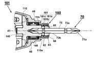
- the structure of the tip tool holding portion 180 of the conventional impact tool 101 will be described with reference to FIG.
- FIG. 9 is a partial vertical sectional view showing the internal structure of the conventional impact tool 101.
- a speed reduction mechanism 20 using planetary gears is provided on the front side of the motor 4 to drive the striking mechanism 130.
- the spindle 31 and the hammer 33 constituting the striking mechanism 130 are held via the steel balls 36 arranged in the cam groove, and the hammer 33 can be retracted axially rearward by the hammer spring 35 arranged at the rear end. It is composed.
- the retracted hammer 33 rotates while being pushed back forward by the hammer spring 35, and hits the anvil 140.
- the anvil 140 is held by the bearing 148 in the hammer case 110.
- the anvil 140 is formed with a mounting hole 142 having a hexagonal cross section extending axially rearward from the front end portion, and a tip tool holding portion 180 is provided at the tip portion of the anvil 140.
- Through holes 146 are formed at two locations in the circumferential direction near the tip of the anvil 140, and the steel balls 85 are housed therein.
- a sleeve 181 is provided on the outer peripheral side of the steel ball 85.
- a coil spring 82 that urges the sleeve 181 to the rear side is mounted on the inside of the sleeve 181. The coil spring 82 is held by the washer 83 held by the tomewa 84 so as not to come off to the front side.
- the sleeve 181 is normally located on the rear side (position for locking the tip tool 70) when viewed in the direction of the rotation axis A1 due to the urging force of the coil spring 82.
- the steel ball 85 can be moved to the outside in the radial direction, and the tip tool 70 is unlocked. It can be attached or detached.
- the present invention has been made in view of the above background, and an object of the present invention is to provide a rotary tool in which the rotary tool is miniaturized. Another object of the present invention is to provide a rotary tool having a compact tip tool holding portion without changing the number of parts and the assembly process. Still another object of the present invention is to provide a rotary tool in which a part of a case accommodating a power transmission mechanism is used as a part of a component of a tip tool holding portion.
- a drive source a transmission mechanism driven by the drive source, a case accommodating the transmission mechanism, and a mounting hole rotated by the transmission mechanism to attach a tip tool to the inside of the tip side.
- the output shaft is formed, the sleeve that is attached to the output shaft and switches between the fixed state and the open state of the tip tool, and the output shaft is formed with a through hole that penetrates from the inside to the outside of the mounting hole in the radial direction.
- a rotary tool provided with a regulating member that prevents the tip tool from coming off by being held movably in the through hole in the radial direction so that at least a part of the regulating member and at least a part of the case overlap.
- the sleeve is held on the output shaft so as to be movable in the axial direction, and has a first defining portion that defines the first position of the regulating member in the outer direction, and the case is the first position of the regulating member. It is configured to have a second regulation part that regulates a second position located radially outward of.
- the sleeve can be positioned by movement in a fixed position that limits the radial movement of the regulating member and a removable position that moves from the fixed position and does not restrict the radial movement of the regulating member. Yes, the sleeve is urged by the urging member to return to a fixed position. Further, when the sleeve is in the detachable position, insertion and removal of the tip tool into the mounting hole are permitted, and when the sleeve is in the fixed position, insertion and removal of the tip tool into the mounting hole is restricted by the regulating member.
- the first specified part of the sleeve and the second specified part of the case overlap in the radial direction
- the first specified part of the sleeve is the case. It is configured so as not to overlap in the radial direction with the second regulation part of.
- the second regulation part of the case restricts the radial movement of the regulating member when the sleeve is in the removable position.
- the regulating member is a steel ball
- the through hole is configured with a radial inner opening smaller than the steel ball diameter and a radial outer opening larger than the diameter of the steel ball.
- the steel ball can be inserted into the through hole from the outside of the output shaft, but the steel ball cannot be inserted into the through hole from the mounting hole side of the output shaft.
- the tip portion where the sleeve of the output shaft is movably held is formed thinly with a step on the outer peripheral surface of the cylindrical portion, the through hole is arranged in the thinly formed portion, and the fixing position of the sleeve is a step. It is defined by abutting on.
- the case has a bell shape with a through hole on the bottom surface, and the second specified portion of the case is configured to extend in the longitudinal direction of the output shaft.
- the present invention has a striking mechanism using a hammer and an anvil, and the anvil is formed integrally with the output shaft and extends radially outward behind the output shaft.
- a mounting hole having a plurality of blades and formed in the axial direction from the tip opening of the output shaft is configured to extend to the rear of the front end position of the blade.
- the output shaft has a step at the rear of the mounting hole in the axial direction, and is formed so that the diameter on the rear end side of the step is large and the diameter on the front end side is small.
- the annular member is defined by the tomewa on the front side position of the output shaft, and the spring urges the abutting portion of the sleeve axially rearward.
- the regulating member moves backward and radially outward against the force of the spring to allow the tip tool to be inserted into the output shaft, and the action of the spring allows the tip tool to be inserted into the tip tool.
- the regulating member fits into the formed recess.
- the contact portion of the sleeve is formed at the rear end position of the cylindrical portion that accommodates the spring on the inner peripheral side.
- a contact portion that regulates the first position of a regulating member such as a steel ball to the outside in the radial direction and a second position that is located radially outside the first position of the regulating member are provided on the sleeve.
- both the regulating parts for regulating were provided, it is no longer necessary to provide the regulating part for regulating the second position on the sleeve according to the present invention.
- the output shaft portion can be shortened, and the case is configured to also serve as a retaining portion for the steel ball, so that it is not necessary to provide a retaining portion for the steel ball, which was conventionally provided in the sleeve, and the sleeve is axially oriented.
- the fitting portion is configured to consist of a rear shaft portion provided so as to extend rearward from the rear end of the anvil and a groove provided at the front end of the spindle into which the rear shaft portion is inserted. Sufficient strength can be ensured because the wall is not thinned on the rear side of the bottom of the tool mounting hole.
- FIG. 1 It is a vertical cross-sectional view which shows the whole impact tool 1 which concerns on embodiment of this invention. It is a partially enlarged view of the body part 2a of FIG. It is a perspective view of the hammer 33 and the anvil 40 of FIG. It is a figure for demonstrating the positional relationship in the radial direction of the steel ball 85 in the tip tool holding part 80 of FIG. It is a figure explaining the structure and movement of the tip tool holding part 80 of FIG. 1 (the 1). It is a figure explaining the structure and movement of the tip tool holding part 80 of FIG. 1 (the 2). It is a figure explaining the structure and movement of the tip tool holding part 80 of FIG. 1 (the 3). It is a figure explaining the structure and movement of the tip tool holding part 80 of FIG.
- the 4 It is a vertical cross-sectional view which shows the internal structure of the body part 102a of the conventional impact tool 101. It is a figure explaining the structure and movement of the tip tool holding part 180 of the conventional impact tool 101 (the 1). It is a figure explaining the structure and movement of the tip tool holding part 180 of the conventional impact tool 101 (the 2). It is a figure explaining the structure and movement of the tip tool holding part 180 of the conventional impact tool 101 (the 3).
- the impact tool 1 will be used as an example of the rotary tool, the same parts will be designated by the same reference numerals, and the repeated description will be omitted. Further, in the present specification, the front-back, left-right, and up-down directions are described as the directions shown in the drawings.
- FIG. 1 is a vertical cross-sectional view showing the internal structure of the impact tool 1 according to the embodiment of the present invention.
- the impact tool 1 uses the electric power of the rechargeable battery 90 to drive the transmission mechanisms (20, 30) using a motor as a drive source to rotate the output shaft (40).
- the transmission mechanism of the impact tool 1 is composed of a deceleration mechanism 20 and a striking mechanism 30, converts the rotational force of the motor 4 into an intermittent striking force in the rotational direction of the output shaft, and is mounted on the output shaft (anvil 40). Rotate the tip tool.
- the housing of the impact tool 1 is mainly composed of a main body housing 2 (2a, 2b, 2c) made of synthetic resin and a metal hammer case 10 for accommodating the striking mechanism 30.
- the main body housing 2 is composed of three parts, that is, a body part 2a formed in a tubular shape, a handle part 2b which is a part held by an operator with one hand, and a battery mounting part 2c for attaching a detachable battery 90. Will be done.
- the handle portion 2b extends downward so as to be substantially orthogonal to the central axis (rotation axis A1) of the body portion 2a, and controls the on or off of the motor at the position where the index finger is located when the operator grips it.
- Trigger switch 6 for the purpose is accommodated.
- An operation lever (trigger lever 6a) is provided on the front side of the trigger switch 6.
- a forward / reverse switching lever 7 for switching the rotation direction of the motor is provided above the rear of the trigger lever 6a.
- the trigger switch 6 turns on the rotation of the motor 4 by pulling the trigger lever 6a with a finger, that is, by moving the trigger lever 6a to the rear side, and cancels the pulling operation of the trigger lever 6a to rotate the motor 4. Turn off.
- the type and structure of the trigger switch 6 are arbitrary, and not only a slide-type trigger lever 6a, but also a trigger switch having a swing-type trigger lever that swings around a swing shaft, and a touch. Any switch mechanism such as a button type switch may be used.
- the hammer case 10 has a tapered cup shape or a bell shape, and has a large circular opening 10e on the rear side, and a through hole 10a through which the anvil 40 penetrates is formed in the center of the front end side, which is the bottom surface.
- the hammer case 10 is an integral piece of metal, and is fixed by being sandwiched between the body portions 2a of the left-right split type main body housing 2.
- a motor 4, a speed reduction mechanism 20 using planetary gears, and a striking mechanism 30 are arranged side by side on the rotation axis A1 on the tubular body portion 2a.
- a battery mounting portion 2c is formed in the lower portion of the handle portion 2b to mount the battery 90.
- the battery mounting portion 2c is a diameter-expanded portion formed so as to extend in the radial direction (orthogonal direction) from the central axis in the longitudinal direction of the handle portion 2b.
- the battery 90 is a secondary battery using a lithium ion battery widely used in power tools.
- the type and shape of the battery 90 are arbitrary.
- the battery 90 can be removed from the main body housing 2 by moving the battery 90 relative to the main body housing 2 while pushing the release button 91.
- the power source of the impact tool 1 of this embodiment is arbitrary, and a commercial power source may be used via an AC power cable instead of using the battery 90 as a power source.
- the main body housing 2 is made of synthetic resin manufactured in a two-part format on the left and right, and is fixed by using a plurality of screws (only the screw 19d is shown in the figure).
- a plurality of screw bosses 19a to 19h for screwing are formed on one side (left side) of the main body housing 2, and a plurality of screw holes (not shown) for passing screws are formed on the other side (right side). It is formed.
- the control circuit unit 63 has a control circuit board on which a microcomputer (hereinafter, referred to as “microcomputer”) (not shown) is mounted.
- the control circuit board of the control circuit unit 63 is arranged in a direction substantially perpendicular to the longitudinal central axis of the handle unit 2b.
- a switch holder 64 is provided on the upper surface of the battery mounting portion 2c, and the switch holder 64 has various operation buttons (not visible in the figure) such as a striking strength setting button and a battery 90 remaining amount check button, and corresponding to the switch holder 64. Indicator lamps, etc. (not visible in the figure) are arranged.
- a brushless DC motor is used for the motor 4, and is driven by an exciting current generated by an inverter circuit.
- the rotation axis 4d of the motor 4 is arranged so that its rotation axis A1 extends in the longitudinal direction of the body portion 2a.
- the stator of the motor 4 is composed of a stator core 4b formed of laminated iron cores and a plurality of magnetic pole pieces, and a coil 4c wound around each tooth of the stator core 4b.
- the rotor 4a generates a magnetic field by a permanent magnet housed inside the laminated iron core.
- a cooling fan 61 is provided on the front side in the axial direction of the motor 4 and coaxially with the rotating shaft 4d.
- the cooling fan 61 rotates in synchronization with the motor 4 to suck outside air from the air intake port 17 on the rear side of the main body housing 2, cools the motor 4, and then is formed on the outer peripheral side of the cooling fan 61. Do not exhaust from the air outlet.
- the rotating shaft 4d of the motor 4 is pivotally supported by a bearing 8a on the front side of the stator core 4b and a bearing 8b on the rear side.
- a drive circuit board 62 is arranged between the stator core 4b and the bearing 8b, which is rearward in the axial direction of the motor 4.
- the drive circuit board 62 is equipped with an inverter circuit composed of three magnetic detection means for detecting the magnetic field of a permanent magnet contained in a rotor and six semiconductor switching elements such as FETs (Field effect transistors). It is formed of an annular printed circuit board.
- a commercially available Hall IC can be used as the magnetic detection means, and a plurality (for example, three) Hall ICs are mounted at predetermined intervals at positions facing the permanent magnets of the rotor.
- the speed reduction mechanism 20 reduces the output of the motor 4 at a predetermined reduction ratio and transmits it to the spindle 31.
- a striking mechanism 30 is provided on the output side of the speed reduction mechanism 20, and the striking mechanism 30 rotates the anvil 40, which is an output shaft.
- a mounting hole 42 for mounting the tip tool 70 (see FIG. 5 described later) is provided at the tip of the anvil 40, and a tip tool holding portion 80 is provided near the opening of the mounting hole 42.
- FIG. 2 is a partially enlarged view of the body portion 2a of FIG.
- the reduction mechanism 20 is provided in a space between the sun gear 21 fixed to the tip of the rotating shaft 4d of the motor 4, the ring gear 25 provided on the outer peripheral side of the sun gear 21 so as to surround the sun gear 21 at a distance, and the space between the sun gear 21 and the ring gear 25. It is configured to include a plurality of (for example, two) planetary gears 22 to be arranged.
- the sun gear 21 is a spur gear that serves as an input unit for the reduction mechanism 20.
- the ring gear 25 is also called an outer gear, and a gear is formed on the inner peripheral surface of a ring-shaped outer cylinder portion.
- the outer peripheral surface of the ring gear 25 is inserted inside the inner cover 28, and the inner cover 28 is held non-rotatably with respect to the main body housing 2.
- the planetary gear 22 rotates so as to be meshed with the outer peripheral side gear surface of the sun gear 21 and the inner peripheral side gear surface of the ring gear 25.
- the planetary gear 22 is pivotally supported by a disk-shaped portion at the rear end of the spindle 31, and the planetary gear 22 revolves around the sun gear 21 while rotating around the shaft 23 pivotally supported by the spindle 31.
- the sun gear 21 rotates in synchronization with the rotation, and the rotational force of the sun gear 21 is decelerated at a predetermined ratio and transmitted to the spindle 31.
- the inner cover 28 is a part manufactured by integrally molding a synthetic resin, and is held by the body portion 2a of the main body housing 2 so as to be sandwiched from the left and right directions.
- the inner cover 28 holds two bearings 8a and 9 provided, and is centered so that the rotation shaft 4d of the motor 4 and the rotation center of the spindle 31 are coaxial.
- the bearing 8a held by the inner cover 28 is for supporting the rotating shaft 4d of the motor 4, and for example, a ball bearing is used.
- the bearing 9 held by the inner cover 28 is for axially supporting the rear end of the spindle 31, and for example, a ball bearing is used.
- a hammer spring 35 is provided on the front side of the disc portion on the rear side of the spindle 31 and between the hammer 33 and the hammer 33.
- the hammer spring 35 urges the hammer 33 to the front side (anvil 40 side).
- a spindle cam groove 32 is formed on the outer peripheral surface of the spindle 31.
- the spindle 31 is manufactured by integral molding of metal due to its strength.
- the hammer 33 is arranged on the outer peripheral side of the shaft portion of the spindle 31, and hammer cam grooves 34a and 34b (see FIG. 3 described later), which are not shown, are formed on the inner peripheral surface.
- the hammer 33 is held by a cam mechanism using a steel ball 36, and the outer peripheral surface of the spindle 31 and a part of the inner peripheral surface of the hammer 33 come into contact with each other.
- the rotating body of the spindle 31 and the anvil 40 is pivotally supported by the inner wall of the hammer case 10 by the bearing 48 on the front side, and is supported by the hammer case 10 by the ball type bearing 9 on the rear side via the inner cover 28.
- a needle bearing is used as the bearing 48.
- the needle of the bearing 48 rotates so as to abut on the outer peripheral surface of the spindle portion 41, and the outer shell of the bearing 48 is held by the bearing holding portion 10d of the hammer case 10.
- An oil seal 49 is attached to the front surface of the outer shell of the bearing 48 to prevent the grease filled in the hammer case 10 from leaking out from the inside of the hammer case 10.
- the hammer 33 rotates in conjunction with the rotation of the spindle 31, but when the reaction force received from the tip tool becomes large, the steel ball 36 of the cam mechanism moves.
- the relative positions of the hammer 33 and the spindle 31 in the rotational direction fluctuate slightly, and the hammer 33 moves significantly to the rear side. Since the hammer 33 is always urged to the front side with respect to the spindle 31 by the hammer spring 35, the movement of the hammer 33 to the rear side is a movement while compressing the hammer spring 35.
- the contact length between the striking claw of the hammer 33 and the blade portion (struck claw) of the anvil 40 in the front-rear direction becomes smaller, and when the contact length reaches the position of 0, the anvil 40 of the hammer 33 Will be disengaged from.
- the tip tool holding portion 80 includes a mounting hole 42 having a hexagonal cross section extending axially rearward from the front end portion of the anvil 40, a steel ball 85 formed at two locations in the circumferential direction, and a sleeve 81 provided on the outer peripheral side. Consists of including.
- a bearing holding portion 10d for holding the bearing 48 and a cylindrical inner surface 10b for regulating the radial outer movable limit position of the steel ball 85 are formed in the vicinity of the through hole 10a at the tip of the hammer case 10.
- a solid needle bearing is used as the bearing 48, but the type of the bearing 48 is arbitrary, and ball bearings such as ball bearings, slide bearings such as metal, and other known bearings may be used.
- a cylindrical rear shaft portion 47 is formed at the rear end portion of the anvil 40, that is, on the rear side of the blade portions 43a to 43c, and the outer peripheral surface of the rear shaft portion 47 is slidable by the fitting hole 31a of the spindle 31. It is supported in a state of being.
- FIG. 3 is a perspective view of the hammer 33 and the anvil 40 of FIG.
- the number of striking claws of the hammer 33 and the number of blades of the anvil 40 are set to three to facilitate the transition from continuous rotation to striking and to realize a high torque impact tool.
- the hammer 33 has a shape in which two tubular portions having different inner diameters are connected in the radial direction on the front side.
- the hammer 33 is made of metal and has a relatively large weight.
- Three striking claws 33a to 33c projecting to the front side (anvil 40 side) in the axial direction are formed at three locations on the outer peripheral side of the front surface of the hammer 33.
- the striking claws 33a to 33c are evenly arranged in the circumferential direction so that their central positions are separated by 120 degrees in the rotation angle when viewed in the rotation direction.
- Hammer cam grooves 34a and 34b are formed on the inner peripheral side of the hammer 33 and on the portion facing the outer surface (cylindrical surface) of the spindle 31.
- the hammer cam grooves 34a and 34b are recesses having a substantially trapezoidal outline when the inner peripheral surface of the hammer 33 is developed in a plane, and together with the spindle cam groove 32, restrict the movement of the steel ball 36 (see FIG. 2). Form a space.
- the anvil 40 is manufactured by integral molding of metal, and three blade portions 43a to 43c are formed behind the cylindrical spindle portion 41.
- the spindle portion 41 is an output shaft of a rotary tool, and a mounting hole 42 having a hexagonal cross section is formed in a portion from the front end portion to the inner portion thereof for mounting the tip tool.
- Two through holes 46 (only one can be seen in FIG. 3) penetrating in the radial direction are formed in the middle of the portion where the mounting hole 42 is formed in the front-rear direction.
- the through holes 46 are formed at two locations 180 degrees apart in the radial direction.
- the length of the spindle portion 41 in the bearing holding surface 41a direction is made shorter than that of the conventional anvil 140, and the axial length of the sleeve 81 is also shown in FIG. It was formed shorter than the conventional sleeve 181.
- a step portion 41d is formed between the bearing holding surface 41a and the tip tool holding portion mounting surface 41b, and the through hole 46 is arranged at a position adjacent to the step portion 41d.
- a steel ball 85 (see FIG. 2), which is a component of the tip tool holding portion 80, is arranged in the through hole 46.
- a cylindrical bearing holding surface 41a is formed between the through hole 46 and the blade portions 43a to 43c when viewed in the axial direction, and the bearing holding surface 41a slides on the bearing 48 (see FIG. 2). It becomes a surface. In this way, the front side of the anvil 40 is rotatably supported with respect to the hammer case 10 (see FIG. 2) via the bearing 48 (see FIG. 2).
- the three blade portions 43a to 43c have a shape extending radially outward in the vicinity of the rear end of the main shaft portion 41, and are formed at positions separated by 120 degrees in the circumferential direction.
- a tapered reinforcing portion 41e is provided near the boundary between the blade portions 43a to 43c and the bearing holding surface 41a to increase the strength of the anvil 40.
- the side surfaces of the blade portions 43a to 43c in the rotational direction are hit surfaces that are hit by the circumferential surfaces of the hitting claws 33a to 33c of the hammer 33. Further, the front side portion of the blade portions 43a to 43c in the axial direction serves as an abutting surface with the washer 39.
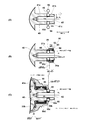
- FIG. 4 is a diagram for explaining the radial positional relationship of the steel ball 85 with respect to the spindle portion of the tip tool holding portion 80.
- FIG. 4A is a partially enlarged view of the spindle portions 41 (41a, 41b) of the anvil 40.
- the spindle portions 41 (41a, 41b) which are the output shafts of the rotary tool, are formed with mounting holes 42 formed from the front to the rear in the axial direction.
- the mounting hole 42 has a hexagonal cross-sectional shape orthogonal to the axis.
- the front side of the spindle portions 41 (41a, 41b) has a tip tool holding portion mounting surface 41b having a radius of R 1 on the outer peripheral surface, and the outer peripheral surface on the rear side has a bearing holding surface 41a having a radius of R 2 and is high in the radial direction. A difference of t is formed.
- the connecting portion between the bearing holding surface 41a and the tip tool holding portion mounting surface 41b is a step portion 41d. Two through holes 46 penetrating in the radial direction are formed near the rear end of the tip tool holding portion mounting surface 41b.
- the through hole 46 is formed inside the mounting hole 42 so as to penetrate two parallel inner wall surfaces facing each other, and the circumferential position of the through hole 46 is parallel when viewed in terms of the cross-sectional shape of the inner wall surface. It is placed in the center of each of the two sides.
- the size of the through hole 46 is such that the steel ball 85 can be accommodated, the steel ball 85 can be easily moved in the radial direction, and the steel ball 85 has a gap in the through hole 46 with less rattling. It is formed.
- the opening 46a on the outer peripheral side of the through hole 46 is slightly larger than the diameter of the steel ball 85 so that the steel ball 85 can be inserted, but the opening 46b on the inner peripheral side of the through hole 46 is a mounting hole on the inner side of the steel ball 85. It is slightly smaller than the diameter of the steel ball 85 so that it cannot pass through to the 42 side.
- a circumferential groove 41c for holding the tomewa 84 is formed near the front end of the tip tool holding portion mounting surface 41b.
- FIG. 4B shows a state in which the sleeve 81 is attached and the tip tool holding portion 80 is assembled.
- the sleeve 81 is formed so that the inner diameter of the large diameter portion 81a on the front side is large enough to have a gap from the outer peripheral surface of the tip tool holding portion mounting surface 41b, and is biased between the sleeve 81 and the tip tool holding portion mounting surface 41b. It is configured to accommodate the coil spring 82, which is a member.
- the rear side of the sleeve 81 is a small diameter portion 81b having a small diameter.
- the inner peripheral surface of the small-diameter portion 81b is the radius R 1 of the outer peripheral surface of the tool bit holder mounting surface 41b, is of a size that plus clearance extent slidable.
- the radius of the inner peripheral surface of the sleeve 81 can be said to substantially equal to the radius R 1 of the outer peripheral surface of the tool bit holder mounting surface 41b.
- the sleeve 81 is urged to move in the direction of the arrow 75a by a coil-type coil spring 82 interposed between the step portion 81c between the large diameter portion 81a and the small diameter portion 81b and the washer 83.
- the position of the washer 83 which is an annular member, is defined by the tomewa 84 on the front side.
- the normal position of the sleeve 81 is the rear position (fixed position for fixing the steel ball 85) shown in FIG. 4 (B), and the inside of the small diameter portion 81b comes into contact with the steel ball 85 at this fixed position.
- the inside of the small diameter portion 81b becomes the first defining portion that defines the first position of the steel ball 85.
- the sleeve 81 is restricted from moving backward in the axial direction by abutting on the step portion 41d.
- FIG. 4C is a diagram showing the positional relationship between the hammer case 10 and the steel ball 85 before the sleeve 81 is attached.
- the front through hole 10a is formed to be sufficiently small, and the movement restriction position (second position) of the steel ball 85 to the outside in the radial direction is restricted.
- the hammer case 10 comes into contact with the steel ball 85 at the second position to prevent the steel ball 85 from coming off from the through hole 10a.
- the portion that can come into contact with the steel ball 85 has a cylindrical inner surface 10b.
- the position of the inner surface of the cylinder 10b on the front side in the rotation axis A1 direction is formed so as to extend to the front side of the center position of the steel ball 85 in the rotation axis A1 direction.
- An annular wall surface 10c extending in the radial direction is formed on the outer peripheral side of the inner surface 10b of the cylinder, and is connected to the front end portion of the cylindrical bearing holding portion 10d that holds the bearing 48.
- the anvil 40 is attached to the hammer case 10 via the bearing 48, but in the conventional assembly work of the impact tool 101 shown in FIG. 9, after the bearing 48 and the anvil 140 are fixed to the hammer case 110.
- the steel ball 85 could be attached from the outside of the hammer case 110.
- the anvil 40 is incorporated into the hammer case 10 as shown in FIG. 4 (C), and then the sleeve 81 or the like is attached as shown in FIG. 4 (B).
- the sleeve 81 after mounting the steel ball 85 may be assembled in the same manner as the conventional impact tool 101.
- FIG. 5 shows a state in which the sleeve 81 of the tip tool holding portion 80 is not operated, and the sleeve is in the fixed position.
- the sleeve 81 is urged to the rear side with the tomewa 84 as a fulcrum by the action of the coil spring 82, and the rear end surface of the sleeve 81 is in contact with the step portion 41d.
- the inside of the small diameter portion 81b of the sleeve 81 comes into contact with the steel ball 85, a part of the steel ball 85 is in a state of protruding into the mounting hole 42.
- the tip tool 70 has a plus or minus shape formed on both ends, respectively, and this bit is commercially available as a standard product.
- the cross-sectional shape of the spindle portion 72 of the tip tool 70 is a regular hexagon, and the cross-sectional shape of the mounting hole 42 of the impact tool 1 is also formed into a regular hexagon in accordance with the tip tool 70.
- the tip portions 71a and 71b at both ends of the tip tool 70 have the same or different shapes, and when the tip portion 71a of the tip tool 70 is used for tightening work, the tip portion 71b side is provided with the mounting hole 42. When the tip portion 71b is used for tightening work, the tip portion 71a side is inserted into the mounting hole 42.
- recesses 73a and 73b having a semicircular cross-sectional shape and continuous in the circumferential direction are formed.
- FIG. 6 is a cross-sectional view showing a state in which the tip tool 70 is inserted rearward in the axial direction without the operator operating the sleeve 81.
- the slope of the tip portion 71b formed in a tapered shape of the tip tool 70 abuts on the inner protruding portion of the steel ball 85, thereby preventing the tip tool 70 from moving further backward. That is, the tip tool 70 cannot be attached unless the operator operates the sleeve 81.
- FIG. 7 is a cross-sectional view showing a state in which the tip tool 70 is being inserted rearward in the axial direction with the sleeve 81 moved in the direction of the arrow 75b.
- the sleeve 81 is moved forward as shown by the arrow 75b, the position of the small diameter portion 81b of the sleeve 81 shifts from the radial outside of the steel ball 85 to the front side, so that the sleeve 81 and the steel ball 85 are in contact with each other. Is released. This is the state in which the tip tool 70 is switched to the removable state by the sleeve 81.
- the steel ball 85 is guided by the tip portion 71b of the tip tool 70 formed obliquely and moves outward in the radial direction. As a result of this movement, the amount of protrusion of the steel ball 85 into the mounting hole 42 becomes zero, so that the insertion of the tip tool 70 into the mounting hole 42 is not hindered. Can be inserted up to. Since the maximum amount of radial movement of the steel ball 85 that has moved outward in the radial direction is limited as the second position by the inner surface 10b of the cylinder formed in the hammer case 10, the steel ball 85 may fall off from the anvil 40. Absent.
- FIG. 10 is a diagram for explaining the structure and movement of the tip tool holding portion 180 of the conventional impact tool 101, in which the sleeve 181 is in a fixed position defining the first position of the steel ball 85 in the outward direction. Shows the case.
- a tip tool holding portion 180 is attached to the tip of the anvil 140.
- the anvil 140 is formed with a slightly smaller diameter at the tip of the spindle.
- Two through holes 146 penetrating in the radial direction are formed in the narrowly formed portion, and the steel ball 85 is arranged from the outside in the radial direction.
- the sleeve 181 is formed with a large diameter portion 181a, a small diameter portion 181c, and an inner protruding portion 181b having a reduced inner diameter at a connecting portion thereof.
- the inner protrusion 181b for preventing the steel ball 85 from moving outward in the radial direction is in a position facing the steel ball 85.
- a compression type coil spring 82 is arranged inside the large diameter portion 181a of the sleeve 181 and between the tip tool holding portion mounting surface 41b, and the coil spring 82 is compressed to the rear side by the washer 83 from the front side thereof. Then, it is fixed with a tomewa 84. In this way, the sleeve 181 is fixed in a state of being urged to the rear side by the coil spring 82.
- FIG. 11 shows a state in which the sleeve 181 is moved forward in the direction of the rotation axis A1 from the state of FIG.
- the small diameter portion 181c is located on the outer peripheral surface of the steel ball 85.
- the steel ball 85 moves radially outward from the state shown in FIG. 10 (the state in which the first movement position in the outer direction is defined), and the second position located radially outside the first position. Can be moved to.
- the tip tool 70 can be inserted into the mounting hole 142 of the anvil 140.
- FIG. 12 shows a state in which the tip tool 70 is inserted into the mounting hole 142 of the anvil 140 to a specified position, and then the movement is released to the front side of the sleeve 181.
- the restoring force of the coil spring 82 causes the sleeve 181 to return to the same normal position (fixed position) as in FIG.
- the steel ball 85 projects inward from the mounting hole 142.
- the recess 73b of the tip tool 70 is located inside the steel ball 85, the tip tool 70 can be locked so as not to move in the rotation axis A1 direction.
- the first position and the second position of the steel ball 85 are defined only by the sleeve 181 and the hammer case 110 has a configuration that does not act on the steel ball 85 at all.
- the second position located radially outside the first position of the steel ball 85 is defined by the inner surface 10b of the cylinder of the hammer case 10.
- the portion of the conventional sleeve 181 corresponding to the small diameter portion 181c in FIG. 10 can be omitted, and the total length of the sleeve 81 can be shortened.
- FIG. 8 shows a state (fixed state of the tip tool 70) after the tip tool 70 is inserted from the state of FIG. 7 until it hits the rear in the axial direction, and then the operator releases the movement of the sleeve 81 to the front side. ..
- the sleeve 81 that has moved to the detachable position against the urging force of the coil spring 82 is moved to the detachable position by the restoring force of the coil spring 82 as shown by the arrow 75a. Return to the original position (fixed position).
- the steel ball 85 is moved inward in the radial direction.
- the steel ball 85 keeps protruding into the mounting hole 42, and the protruding portion is housed inside the recess 73b. It is maintained in the same state as it was.
- the sleeve 81 When the steel ball 85 moves to the innermost peripheral side of the mounting hole 42, the sleeve 81 is not restricted from moving to the rear side by the steel ball 85, so that the sleeve 81 moves until it comes into contact with the step portion 41d by the restoring force of the coil spring 82.
- the sleeve 81 will remain in the normal position (fixed position) for fixing the steel ball 85.
- the steel ball 85 cannot move outward in the radial direction. Therefore, even if the operator tries to pull out only the tip tool 70 forward, the tip is fitted by the fitting of the steel ball 85 and the recess 73b. The movement of the tool 70 is blocked. In the state shown in FIG. 8, the trigger of the impact tool 1 is pulled to rotate the motor 4.
- the operator moves the sleeve 81 axially forward (in the direction of arrow 75b in FIG. 7). Then, the coil spring 82 is compressed and the tip tool holding portion 80 is in the same state as in FIG. 7.
- the position of the small diameter portion 81b shifts forward, so that the holding state of the steel ball 85 on the outer side in the radial direction is released.
- the steel ball 85 is guided by the slope of the recess 73b and moves outward in the radial direction, and finally the steel ball 85 moves from the inner wall of the tip tool 70. Will be located on the outside (state in FIG. 7).
- FIG. 7 shows a state in which the steel ball 85 is outside the outer surface of the tip tool and is in the outermost position (second position) in the radial direction in contact with the inner surface 10b of the cylinder for ease of understanding.
- the tip tool 70 can be attached and detached as long as the steel ball 85 can be retracted radially outward to the extent that it does not come into contact with the outer surface of the tip tool 70.
- the sleeve 81 When the operator stops pulling the sleeve 81 after the tip tool 70 is pulled out, the sleeve 81 returns to the original position, that is, the state shown in FIG. 5 due to the restoring force of the coil spring 82. As described above, in the present embodiment, by moving the sleeve 81 in the direction away from the main body side, the steel ball 85 can be separated from the small diameter portion 81b of the sleeve 81 and can be moved outward in the radial direction. The engagement state of the tool 70 with the recess 73b is released, and the tip tool 70 can be attached and detached. This operation procedure is the same as that of the tip tool holding portion 180 of the conventional impact tool 1.
- the sleeve 81 defines the first position of the regulating member (steel ball, etc.) in the tip tool holding portion 80 to the outside in the radial direction, and the second position to the outside in the radial direction from the first position is regulated. Since the regulating portion is provided on the hammer case 10 side, the axial length of the sleeve 81 can be shortened. As a result, the total length of the anvil, which is the output shaft, can be shortened, and the rotary tool can be made smaller and lighter. In addition, by achieving miniaturization and weight reduction of the rotary tool, it was possible to improve the maneuverability of the rotary tool.
- the present invention has been described above based on Examples, the present invention is not limited to the above-mentioned Examples, and various modifications can be made without departing from the spirit of the present invention.
- the impact tool 1 has been described as an example of the rotary tool, but a bit or the like having a hexagonal cross-sectional shape is mounted at the tip of the output shaft. If it is a rotary tool, it can be similarly applied to a rotary tool other than the impact tool 1, for example, a driver drill.
- the sleeve of the tip tool holding portion is not limited to the one operated in the axial direction, and the first position in the radial direction of the steel ball is defined by rotating around the rotation axis A1, or the regulated movement position is determined.
- the configuration of the present invention can be realized even if the configuration is such that the movement position is not restricted and the second position is restricted by the hammer case when the sleeve is not restricted or the movement position is not restricted.
Landscapes
- Engineering & Computer Science (AREA)
- Mechanical Engineering (AREA)
- Percussive Tools And Related Accessories (AREA)
- Gripping On Spindles (AREA)
- Drilling And Boring (AREA)
- Jigs For Machine Tools (AREA)
Priority Applications (4)
| Application Number | Priority Date | Filing Date | Title |
|---|---|---|---|
| CN202080082453.7A CN114761178B (zh) | 2019-12-26 | 2020-11-27 | 旋转工具 |
| DE112020006383.6T DE112020006383T5 (de) | 2019-12-26 | 2020-11-27 | Drehendes Werkzeug |
| JP2021567097A JP7338705B2 (ja) | 2019-12-26 | 2020-11-27 | 回転工具 |
| US17/779,125 US11980948B2 (en) | 2019-12-26 | 2020-11-27 | Rotary tool |
Applications Claiming Priority (2)
| Application Number | Priority Date | Filing Date | Title |
|---|---|---|---|
| JP2019-235912 | 2019-12-26 | ||
| JP2019235912 | 2019-12-26 |
Publications (1)
| Publication Number | Publication Date |
|---|---|
| WO2021131495A1 true WO2021131495A1 (ja) | 2021-07-01 |
Family
ID=76574302
Family Applications (1)
| Application Number | Title | Priority Date | Filing Date |
|---|---|---|---|
| PCT/JP2020/044286 Ceased WO2021131495A1 (ja) | 2019-12-26 | 2020-11-27 | 回転工具 |
Country Status (5)
| Country | Link |
|---|---|
| US (1) | US11980948B2 (https=) |
| JP (1) | JP7338705B2 (https=) |
| CN (1) | CN114761178B (https=) |
| DE (1) | DE112020006383T5 (https=) |
| WO (1) | WO2021131495A1 (https=) |
Cited By (2)
| Publication number | Priority date | Publication date | Assignee | Title |
|---|---|---|---|---|
| US20230023681A1 (en) * | 2021-07-23 | 2023-01-26 | Nanjing Chervon Industry Co., Ltd. | Power tool |
| JP2023090312A (ja) * | 2021-12-17 | 2023-06-29 | 株式会社マキタ | インパクト工具 |
Families Citing this family (5)
| Publication number | Priority date | Publication date | Assignee | Title |
|---|---|---|---|---|
| US11980948B2 (en) * | 2019-12-26 | 2024-05-14 | Koki Holdings Co., Ltd. | Rotary tool |
| EP4159375A4 (en) * | 2020-05-29 | 2023-12-20 | Koki Holdings Co., Ltd. | PERCUSSION TOOL |
| JP7664047B2 (ja) * | 2021-01-06 | 2025-04-17 | 株式会社マキタ | インパクト工具 |
| JP7675396B2 (ja) * | 2022-06-08 | 2025-05-13 | パナソニックIpマネジメント株式会社 | インパクト回転工具 |
| JP7826130B2 (ja) * | 2022-06-27 | 2026-03-09 | 株式会社マキタ | 電動作業機 |
Citations (3)
| Publication number | Priority date | Publication date | Assignee | Title |
|---|---|---|---|---|
| JP2009248210A (ja) * | 2008-04-02 | 2009-10-29 | Hitachi Koki Co Ltd | 携帯用工具 |
| WO2018163561A1 (ja) * | 2017-03-07 | 2018-09-13 | 株式会社 マキタ | 工具保持装置及び電動工具、インパクト工具 |
| DE102017209160A1 (de) * | 2017-05-31 | 2018-12-06 | Robert Bosch Gmbh | Handwerkzeugmaschinenvorrichtung |
Family Cites Families (39)
| Publication number | Priority date | Publication date | Assignee | Title |
|---|---|---|---|---|
| DE2354168C2 (de) * | 1973-10-30 | 1984-10-04 | Robert Bosch Gmbh, 7000 Stuttgart | Werkzeughalter für einen Bohrhammer |
| US4692073A (en) * | 1985-02-25 | 1987-09-08 | Martindell J Richard | Handle adapter and chuck apparatus for power bits |
| DE20112117U1 (de) * | 2001-07-26 | 2001-10-31 | Zierpka, Günter, 76199 Karlsruhe | Drehmaschine, etwa in Form einer Handbohrmaschine, einer Schlagbohrmaschine, eines Bohrhammers oder eines Akkuschraubers |
| DE10337470A1 (de) * | 2003-08-14 | 2005-03-17 | Atlas Copco Electric Tools Gmbh | Spanneinrichtung für Sechskantbits |
| JP4291173B2 (ja) * | 2004-02-10 | 2009-07-08 | 株式会社マキタ | インパクトドライバ |
| TWM259675U (en) | 2004-06-28 | 2005-03-21 | Bing-Wen Huang | Fast-coupling joint of screwdriver |
| JP5032745B2 (ja) * | 2005-01-24 | 2012-09-26 | 株式会社マキタ | 作業工具 |
| JP4501757B2 (ja) * | 2005-04-11 | 2010-07-14 | 日立工機株式会社 | インパクト工具 |
| CN2868578Y (zh) | 2006-01-16 | 2007-02-14 | 陈家佑 | 手工具的握杆伸缩构造 |
| JP2007203401A (ja) * | 2006-02-01 | 2007-08-16 | Hitachi Koki Co Ltd | インパクト工具 |
| DE202011109498U1 (de) * | 2011-12-27 | 2012-02-13 | Franz Haimer Maschinenbau Kg | Werkzeughalter und Spannsystem mit einem derartigen Werkzeughalter |
| DE102007000453A1 (de) * | 2007-08-20 | 2009-02-26 | Hilti Aktiengesellschaft | Wechselbare Werkzeugaufnahme |
| JP5270197B2 (ja) * | 2008-03-10 | 2013-08-21 | 株式会社マキタ | 打撃工具 |
| JP2009226568A (ja) * | 2008-03-25 | 2009-10-08 | Makita Corp | 打撃工具 |
| JP4674640B2 (ja) * | 2009-01-27 | 2011-04-20 | パナソニック電工株式会社 | インパクト回転工具 |
| US8381830B2 (en) * | 2009-05-05 | 2013-02-26 | Black & Decker Inc. | Power tool with integrated bit retention device |
| BR112012008122A2 (pt) * | 2009-07-29 | 2016-03-01 | Hitachi Koki Kk | ferramenta de impacto |
| JP5440766B2 (ja) * | 2009-07-29 | 2014-03-12 | 日立工機株式会社 | インパクト工具 |
| CN101691029B (zh) | 2009-08-18 | 2011-11-23 | 浙江瑞丰五福气动工具有限公司 | 气动工具的双冲击离合器锤打装置 |
| JP5510807B2 (ja) * | 2010-03-08 | 2014-06-04 | 日立工機株式会社 | インパクト工具 |
| JP5483089B2 (ja) * | 2010-03-11 | 2014-05-07 | 日立工機株式会社 | インパクト工具 |
| DE102010030642A1 (de) * | 2010-06-09 | 2011-12-15 | Robert Bosch Gmbh | Handwerkzeugmaschine mit einer Werkzeugaufnahme |
| JP5468570B2 (ja) | 2011-06-17 | 2014-04-09 | 株式会社マキタ | 打撃工具 |
| US10377022B2 (en) * | 2012-04-30 | 2019-08-13 | Koki Holdings Co., Ltd. | Power tool anvil lock mechanism |
| JP5841011B2 (ja) * | 2012-06-05 | 2016-01-06 | 株式会社マキタ | 回転打撃工具 |
| US9272400B2 (en) | 2012-12-12 | 2016-03-01 | Ingersoll-Rand Company | Torque-limited impact tool |
| JP6032041B2 (ja) | 2013-02-13 | 2016-11-24 | 日立工機株式会社 | インパクト工具 |
| WO2014162862A1 (ja) * | 2013-03-30 | 2014-10-09 | 日立工機株式会社 | 電動工具 |
| JP6198515B2 (ja) * | 2013-08-08 | 2017-09-20 | 株式会社マキタ | インパクト工具 |
| EP3175954B1 (en) * | 2014-07-31 | 2020-12-02 | Koki Holdings Co., Ltd. | Impact tool |
| US10654153B2 (en) * | 2015-01-30 | 2020-05-19 | Koki Holdings Co., Ltd. | Impact tool |
| CN104723262A (zh) | 2015-03-18 | 2015-06-24 | 天津精开科技开发有限公司 | 单手操作索嘴及其工作方法 |
| JP6901898B2 (ja) * | 2017-04-17 | 2021-07-14 | 株式会社マキタ | 回転打撃工具 |
| US20180326565A1 (en) * | 2017-05-12 | 2018-11-15 | Compass Corporation | Tool Bit Coupling Assembly |
| WO2019031275A1 (ja) | 2017-08-10 | 2019-02-14 | 工機ホールディングス株式会社 | 電動工具 |
| JP6987667B2 (ja) * | 2018-02-23 | 2022-01-05 | 株式会社マキタ | インパクト工具 |
| US11219987B2 (en) * | 2019-06-06 | 2022-01-11 | George R Anex | Tool for installation and removal of retention knobs |
| US11980948B2 (en) * | 2019-12-26 | 2024-05-14 | Koki Holdings Co., Ltd. | Rotary tool |
| JP2023077917A (ja) * | 2021-11-25 | 2023-06-06 | 株式会社マキタ | インパクト工具 |
-
2020
- 2020-11-27 US US17/779,125 patent/US11980948B2/en active Active
- 2020-11-27 JP JP2021567097A patent/JP7338705B2/ja active Active
- 2020-11-27 DE DE112020006383.6T patent/DE112020006383T5/de active Pending
- 2020-11-27 WO PCT/JP2020/044286 patent/WO2021131495A1/ja not_active Ceased
- 2020-11-27 CN CN202080082453.7A patent/CN114761178B/zh active Active
Patent Citations (3)
| Publication number | Priority date | Publication date | Assignee | Title |
|---|---|---|---|---|
| JP2009248210A (ja) * | 2008-04-02 | 2009-10-29 | Hitachi Koki Co Ltd | 携帯用工具 |
| WO2018163561A1 (ja) * | 2017-03-07 | 2018-09-13 | 株式会社 マキタ | 工具保持装置及び電動工具、インパクト工具 |
| DE102017209160A1 (de) * | 2017-05-31 | 2018-12-06 | Robert Bosch Gmbh | Handwerkzeugmaschinenvorrichtung |
Cited By (3)
| Publication number | Priority date | Publication date | Assignee | Title |
|---|---|---|---|---|
| US20230023681A1 (en) * | 2021-07-23 | 2023-01-26 | Nanjing Chervon Industry Co., Ltd. | Power tool |
| JP2023090312A (ja) * | 2021-12-17 | 2023-06-29 | 株式会社マキタ | インパクト工具 |
| JP7742295B2 (ja) | 2021-12-17 | 2025-09-19 | 株式会社マキタ | インパクト工具 |
Also Published As
| Publication number | Publication date |
|---|---|
| CN114761178A (zh) | 2022-07-15 |
| JPWO2021131495A1 (https=) | 2021-07-01 |
| US11980948B2 (en) | 2024-05-14 |
| DE112020006383T5 (de) | 2022-10-13 |
| JP7338705B2 (ja) | 2023-09-05 |
| CN114761178B (zh) | 2024-07-05 |
| US20220395911A1 (en) | 2022-12-15 |
Similar Documents
| Publication | Publication Date | Title |
|---|---|---|
| WO2021131495A1 (ja) | 回転工具 | |
| CN112296920B (zh) | 工具保持装置、冲击起子以及电动作业机 | |
| JP6995591B2 (ja) | インパクト工具 | |
| CN115122281B (zh) | 冲击工具 | |
| EP3067156B1 (en) | Rotary impact tool | |
| US20150083451A1 (en) | Power tool | |
| CN106826699A (zh) | 带振动机构的电动工具 | |
| US12337443B2 (en) | Impact tool | |
| US12194601B2 (en) | Impact tool | |
| US20230415309A1 (en) | Electric work machine | |
| JP2023167127A (ja) | インパクト工具 | |
| CN116265196A (zh) | 冲击工具 | |
| CN116265192A (zh) | 冲击工具 | |
| CN110815138B (zh) | 电动工具 | |
| WO2019150651A1 (ja) | 電動工具 | |
| WO2017110229A1 (ja) | 回転工具 | |
| CN213381293U (zh) | 螺钉紧固工具 | |
| WO2021220991A1 (ja) | 作業機及び作業機システム | |
| JP2021035703A (ja) | 動力工具 | |
| WO2019150845A1 (ja) | 電動工具 | |
| CN116265198A (zh) | 电动工具 | |
| JP2021084187A (ja) | インパクト工具 | |
| JP7465647B2 (ja) | ハンマドリル | |
| JP2019048382A (ja) | インパクト工具 | |
| JP2023167126A (ja) | インパクト工具 |
Legal Events
| Date | Code | Title | Description |
|---|---|---|---|
| 121 | Ep: the epo has been informed by wipo that ep was designated in this application |
Ref document number: 20906312 Country of ref document: EP Kind code of ref document: A1 |
|
| ENP | Entry into the national phase |
Ref document number: 2021567097 Country of ref document: JP Kind code of ref document: A |
|
| 122 | Ep: pct application non-entry in european phase |
Ref document number: 20906312 Country of ref document: EP Kind code of ref document: A1 |