WO2021131237A1 - 画像表示装置および光学部材のセット - Google Patents
画像表示装置および光学部材のセット Download PDFInfo
- Publication number
- WO2021131237A1 WO2021131237A1 PCT/JP2020/038467 JP2020038467W WO2021131237A1 WO 2021131237 A1 WO2021131237 A1 WO 2021131237A1 JP 2020038467 W JP2020038467 W JP 2020038467W WO 2021131237 A1 WO2021131237 A1 WO 2021131237A1
- Authority
- WO
- WIPO (PCT)
- Prior art keywords
- sensitive adhesive
- pressure
- polarizing plate
- adhesive layer
- image display
- Prior art date
- Legal status (The legal status is an assumption and is not a legal conclusion. Google has not performed a legal analysis and makes no representation as to the accuracy of the status listed.)
- Ceased
Links
- 0 CC(CN=O)(CCCC1)C1(C*)N Chemical compound CC(CN=O)(CCCC1)C1(C*)N 0.000 description 2
Images




Classifications
-
- G—PHYSICS
- G02—OPTICS
- G02B—OPTICAL ELEMENTS, SYSTEMS OR APPARATUS
- G02B5/00—Optical elements other than lenses
- G02B5/30—Polarising elements
- G02B5/3025—Polarisers, i.e. arrangements capable of producing a definite output polarisation state from an unpolarised input state
-
- G—PHYSICS
- G02—OPTICS
- G02B—OPTICAL ELEMENTS, SYSTEMS OR APPARATUS
- G02B5/00—Optical elements other than lenses
- G02B5/30—Polarising elements
- G02B5/3025—Polarisers, i.e. arrangements capable of producing a definite output polarisation state from an unpolarised input state
- G02B5/3033—Polarisers, i.e. arrangements capable of producing a definite output polarisation state from an unpolarised input state in the form of a thin sheet or foil, e.g. Polaroid
- G02B5/3041—Polarisers, i.e. arrangements capable of producing a definite output polarisation state from an unpolarised input state in the form of a thin sheet or foil, e.g. Polaroid comprising multiple thin layers, e.g. multilayer stacks
- G02B5/305—Polarisers, i.e. arrangements capable of producing a definite output polarisation state from an unpolarised input state in the form of a thin sheet or foil, e.g. Polaroid comprising multiple thin layers, e.g. multilayer stacks including organic materials, e.g. polymeric layers
-
- B—PERFORMING OPERATIONS; TRANSPORTING
- B32—LAYERED PRODUCTS
- B32B—LAYERED PRODUCTS, i.e. PRODUCTS BUILT-UP OF STRATA OF FLAT OR NON-FLAT, e.g. CELLULAR OR HONEYCOMB, FORM
- B32B7/00—Layered products characterised by the relation between layers; Layered products characterised by the relative orientation of features between layers, or by the relative values of a measurable parameter between layers, i.e. products comprising layers having different physical, chemical or physicochemical properties; Layered products characterised by the interconnection of layers
- B32B7/02—Physical, chemical or physicochemical properties
- B32B7/023—Optical properties
-
- C—CHEMISTRY; METALLURGY
- C09—DYES; PAINTS; POLISHES; NATURAL RESINS; ADHESIVES; COMPOSITIONS NOT OTHERWISE PROVIDED FOR; APPLICATIONS OF MATERIALS NOT OTHERWISE PROVIDED FOR
- C09J—ADHESIVES; NON-MECHANICAL ASPECTS OF ADHESIVE PROCESSES IN GENERAL; ADHESIVE PROCESSES NOT PROVIDED FOR ELSEWHERE; USE OF MATERIALS AS ADHESIVES
- C09J201/00—Adhesives based on unspecified macromolecular compounds
-
- C—CHEMISTRY; METALLURGY
- C09—DYES; PAINTS; POLISHES; NATURAL RESINS; ADHESIVES; COMPOSITIONS NOT OTHERWISE PROVIDED FOR; APPLICATIONS OF MATERIALS NOT OTHERWISE PROVIDED FOR
- C09J—ADHESIVES; NON-MECHANICAL ASPECTS OF ADHESIVE PROCESSES IN GENERAL; ADHESIVE PROCESSES NOT PROVIDED FOR ELSEWHERE; USE OF MATERIALS AS ADHESIVES
- C09J7/00—Adhesives in the form of films or foils
- C09J7/30—Adhesives in the form of films or foils characterised by the adhesive composition
- C09J7/38—Pressure-sensitive adhesives [PSA]
-
- G—PHYSICS
- G02—OPTICS
- G02B—OPTICAL ELEMENTS, SYSTEMS OR APPARATUS
- G02B5/00—Optical elements other than lenses
- G02B5/30—Polarising elements
-
- G—PHYSICS
- G02—OPTICS
- G02F—OPTICAL DEVICES OR ARRANGEMENTS FOR THE CONTROL OF LIGHT BY MODIFICATION OF THE OPTICAL PROPERTIES OF THE MEDIA OF THE ELEMENTS INVOLVED THEREIN; NON-LINEAR OPTICS; FREQUENCY-CHANGING OF LIGHT; OPTICAL LOGIC ELEMENTS; OPTICAL ANALOGUE/DIGITAL CONVERTERS
- G02F1/00—Devices or arrangements for the control of the intensity, colour, phase, polarisation or direction of light arriving from an independent light source, e.g. switching, gating or modulating; Non-linear optics
- G02F1/01—Devices or arrangements for the control of the intensity, colour, phase, polarisation or direction of light arriving from an independent light source, e.g. switching, gating or modulating; Non-linear optics for the control of the intensity, phase, polarisation or colour
- G02F1/13—Devices or arrangements for the control of the intensity, colour, phase, polarisation or direction of light arriving from an independent light source, e.g. switching, gating or modulating; Non-linear optics for the control of the intensity, phase, polarisation or colour based on liquid crystals, e.g. single liquid crystal display cells
- G02F1/133—Constructional arrangements; Operation of liquid crystal cells; Circuit arrangements
- G02F1/1333—Constructional arrangements; Manufacturing methods
- G02F1/1335—Structural association of cells with optical devices, e.g. polarisers or reflectors
-
- G—PHYSICS
- G02—OPTICS
- G02F—OPTICAL DEVICES OR ARRANGEMENTS FOR THE CONTROL OF LIGHT BY MODIFICATION OF THE OPTICAL PROPERTIES OF THE MEDIA OF THE ELEMENTS INVOLVED THEREIN; NON-LINEAR OPTICS; FREQUENCY-CHANGING OF LIGHT; OPTICAL LOGIC ELEMENTS; OPTICAL ANALOGUE/DIGITAL CONVERTERS
- G02F1/00—Devices or arrangements for the control of the intensity, colour, phase, polarisation or direction of light arriving from an independent light source, e.g. switching, gating or modulating; Non-linear optics
- G02F1/01—Devices or arrangements for the control of the intensity, colour, phase, polarisation or direction of light arriving from an independent light source, e.g. switching, gating or modulating; Non-linear optics for the control of the intensity, phase, polarisation or colour
- G02F1/13—Devices or arrangements for the control of the intensity, colour, phase, polarisation or direction of light arriving from an independent light source, e.g. switching, gating or modulating; Non-linear optics for the control of the intensity, phase, polarisation or colour based on liquid crystals, e.g. single liquid crystal display cells
- G02F1/133—Constructional arrangements; Operation of liquid crystal cells; Circuit arrangements
- G02F1/1333—Constructional arrangements; Manufacturing methods
- G02F1/1335—Structural association of cells with optical devices, e.g. polarisers or reflectors
- G02F1/133528—Polarisers
-
- G—PHYSICS
- G09—EDUCATION; CRYPTOGRAPHY; DISPLAY; ADVERTISING; SEALS
- G09F—DISPLAYING; ADVERTISING; SIGNS; LABELS OR NAME-PLATES; SEALS
- G09F9/00—Indicating arrangements for variable information in which the information is built-up on a support by selection or combination of individual elements
-
- G—PHYSICS
- G09—EDUCATION; CRYPTOGRAPHY; DISPLAY; ADVERTISING; SEALS
- G09F—DISPLAYING; ADVERTISING; SIGNS; LABELS OR NAME-PLATES; SEALS
- G09F9/00—Indicating arrangements for variable information in which the information is built-up on a support by selection or combination of individual elements
- G09F9/30—Indicating arrangements for variable information in which the information is built-up on a support by selection or combination of individual elements in which the desired character or characters are formed by combining individual elements
-
- G—PHYSICS
- G09—EDUCATION; CRYPTOGRAPHY; DISPLAY; ADVERTISING; SEALS
- G09F—DISPLAYING; ADVERTISING; SIGNS; LABELS OR NAME-PLATES; SEALS
- G09F9/00—Indicating arrangements for variable information in which the information is built-up on a support by selection or combination of individual elements
- G09F9/30—Indicating arrangements for variable information in which the information is built-up on a support by selection or combination of individual elements in which the desired character or characters are formed by combining individual elements
- G09F9/33—Indicating arrangements for variable information in which the information is built-up on a support by selection or combination of individual elements in which the desired character or characters are formed by combining individual elements being semiconductor devices, e.g. diodes
-
- G—PHYSICS
- G09—EDUCATION; CRYPTOGRAPHY; DISPLAY; ADVERTISING; SEALS
- G09F—DISPLAYING; ADVERTISING; SIGNS; LABELS OR NAME-PLATES; SEALS
- G09F9/00—Indicating arrangements for variable information in which the information is built-up on a support by selection or combination of individual elements
- G09F9/30—Indicating arrangements for variable information in which the information is built-up on a support by selection or combination of individual elements in which the desired character or characters are formed by combining individual elements
- G09F9/35—Indicating arrangements for variable information in which the information is built-up on a support by selection or combination of individual elements in which the desired character or characters are formed by combining individual elements being liquid crystals
-
- H—ELECTRICITY
- H05—ELECTRIC TECHNIQUES NOT OTHERWISE PROVIDED FOR
- H05B—ELECTRIC HEATING; ELECTRIC LIGHT SOURCES NOT OTHERWISE PROVIDED FOR; CIRCUIT ARRANGEMENTS FOR ELECTRIC LIGHT SOURCES, IN GENERAL
- H05B33/00—Electroluminescent light sources
- H05B33/02—Details
-
- H—ELECTRICITY
- H10—SEMICONDUCTOR DEVICES; ELECTRIC SOLID-STATE DEVICES NOT OTHERWISE PROVIDED FOR
- H10K—ORGANIC ELECTRIC SOLID-STATE DEVICES
- H10K59/00—Integrated devices, or assemblies of multiple devices, comprising at least one organic light-emitting element covered by group H10K50/00
- H10K59/80—Constructional details
- H10K59/8791—Arrangements for improving contrast, e.g. preventing reflection of ambient light
Definitions
- the present invention relates to a set of an image display device and an optical member.
- Optical laminates are widely used in image display devices such as mobile phones and notebook personal computers in order to realize image display and / or enhance the performance of the image display.
- image display devices such as mobile phones and notebook personal computers
- a cover glass may be laminated on the outermost surface of the image display device.
- the deformed portion is typically filled with an adhesive for laminating the cover glass.
- bubbles may be generated due to heat treatment or the like in the manufacturing process.
- the present invention has been made to solve the above-mentioned conventional problems, and a main object thereof is to provide an image display device in which a deformed processed portion is filled with an adhesive and bubbles are remarkably suppressed. is there.
- the image display device of the present invention includes an image display cell; a first polarizing element and a first pressure-sensitive adhesive layer, and is laminated on the visual side of the image display cell via the first pressure-sensitive adhesive layer.
- the first polarizing plate and the second polarizing plate have a deformed portion at positions corresponding to each other, and the deformed portion of the first polarizing plate forms a third pressure-sensitive adhesive layer. Is filled with.
- the pressure-sensitive adhesive layer of the third When laminating the pressure-sensitive adhesive layer of the third to the first polarizing plate, storage modulus at 60 ° C. of the pressure-sensitive adhesive constituting the pressure-sensitive adhesive layer of the third is below 1.0 ⁇ 10 5 Pa
- the absolute value of the dimensional shrinkage in the absorption axis direction when the first polarizing plate is heat-treated at 85 ° C. for 24 hours is 0.7% or less.
- it comprises an image display cell; a first polarizing element and a first pressure-sensitive adhesive layer, which is laminated on the visible side of the image display cell via the first pressure-sensitive adhesive layer.
- first polarizing plate and a third pressure-sensitive adhesive layer arranged on the visible side of the first polarizing plate; the first polarizing plate has a deformed portion, and the first polarizing plate has a deformed portion.
- the deformed portion of the polarizing plate is filled with the pressure-sensitive adhesive constituting the third pressure-sensitive adhesive layer, and the third pressure-sensitive adhesive when the third pressure-sensitive adhesive layer is laminated on the first polarizing plate.
- storage modulus at 60 ° C. of the pressure-sensitive adhesive constituting the adhesive layer is not more than 1.0 ⁇ 10 5 Pa, dimensional shrinkage rate of the absorption axis direction when the first polarizer 24 hours of heat treatment at 85 ° C.
- the absolute value of is 0.7% or less.
- the pressure-sensitive adhesive constituting the third pressure-sensitive adhesive layer is a photocurable pressure-sensitive adhesive
- the storage elastic modulus of the photo-curable pressure-sensitive adhesive at 60 ° C. before curing is 1.0 ⁇ 10.
- the storage elastic modulus at 60 ° C. after curing of the photocurable pressure-sensitive adhesive is 5.0 ⁇ 10 3 Pa to 5.0 ⁇ 10 5 Pa, which is 3 Pa to 1.0 ⁇ 10 5 Pa.
- the thickness of the pressure-sensitive adhesive layer of No. 3 is 50 ⁇ m to 500 ⁇ m.
- the photocurable pressure-sensitive adhesive has a gel fraction of 0% to 60% before curing and a gel fraction after curing of 50% to 95%.
- the pressure-sensitive adhesive constituting the third pressure-sensitive adhesive layer is a non-curable pressure-sensitive adhesive, and at 60 ° C. when the third pressure-sensitive adhesive layer is laminated on the first polarizing plate.
- the storage elastic modulus is 1.0 ⁇ 10 3 Pa to 8.0 ⁇ 10 4 Pa, and the thickness of the third pressure-sensitive adhesive layer is 50 ⁇ m to 1000 ⁇ m.
- the elastic modulus of the first pressure-sensitive adhesive layer at 85 ° C. is 5.0 ⁇ 10 4 Pa or more.
- the thickness of the first polarizer is less than 10 ⁇ m.
- the thickness of the first polarizing element is 10 ⁇ m to 20 ⁇ m, the thickness of the first polarizing plate is 100 ⁇ m or less, and the first polarizing plate is heat-shrinked.
- the deformed portion of the first polarizing plate is formed so that the end face of the first pressure-sensitive adhesive layer is located inward in the plane direction with respect to the end face of the first polarizing plate. It has a pressure-sensitive adhesive gap, and the size of the pressure-sensitive adhesive gap is 300 ⁇ m or less.
- the adhesive force between the first pressure-sensitive adhesive layer and the third pressure-sensitive adhesive layer is 2N / 25 mm or more.
- the deformed portion includes a through hole or a machined portion that becomes a recess when viewed in a plan view.
- the recess is a V-shaped notch or a U-shaped notch.
- the image display device further has a cover glass on the visible side of the third pressure-sensitive adhesive layer.
- the image display device has a camera unit at a position corresponding to a deformed portion of the first polarizing plate and the second polarizing plate.
- the image display device is a liquid crystal display device.
- the image display device is an organic EL display device.
- the organic EL display device has a camera unit at a position corresponding to the deformed processing portion of the first polarizing plate.
- a set of optical members is provided.
- This set of optical members includes a first polarizer and a first pressure-sensitive adhesive layer, has a deformed portion, and has an absolute value of dimensional shrinkage in the absorption axis direction when heat-treated at 85 ° C. for 24 hours. It has a first polarizing plate which is 0.7% or less and is arranged on the visual side of the image display cell; a base material and a third pressure-sensitive adhesive layer provided on the base material, and the third plate material is provided.
- the pressure-sensitive adhesive constituting the pressure-sensitive adhesive layer of No. 3 includes a pressure-sensitive adhesive sheet, which fills the deformed portion of the first polarizing plate.
- the pressure-sensitive adhesive constituting the third pressure-sensitive adhesive layer is a photocurable pressure-sensitive adhesive
- the storage elastic modulus of the photo-curable pressure-sensitive adhesive at 60 ° C. before curing is 1.0 ⁇ 10.
- the photocurable pressure-sensitive adhesive after curing of the photocurable pressure-sensitive adhesive is 5.0 ⁇ 10 3 Pa to 5.0 ⁇ 10 5 Pa, which is 3 Pa to 1.0 ⁇ 10 5 Pa.
- the thickness of the pressure-sensitive adhesive layer of No. 3 is 50 ⁇ m to 500 ⁇ m.
- the photocurable pressure-sensitive adhesive has a gel fraction of 0% to 60% before curing and a gel fraction after curing of 50% to 95%.
- the pressure-sensitive adhesive constituting the third pressure-sensitive adhesive layer is a non-curable pressure-sensitive adhesive, and at 60 ° C. when the third pressure-sensitive adhesive layer is laminated on the first polarizing plate.
- the storage elastic modulus is 1.0 ⁇ 10 3 Pa to 8.0 ⁇ 10 4 Pa, and the thickness of the third pressure-sensitive adhesive layer is 50 ⁇ m to 1000 ⁇ m.
- the deformed portion of the first polarizing plate is formed so that the end face of the first pressure-sensitive adhesive layer is located inward in the plane direction with respect to the end face of the first polarizing plate. It has a pressure-sensitive adhesive gap, and the size of the pressure-sensitive adhesive gap is 300 ⁇ m or less.
- the set of optical members includes a second polarizing element, has a deformed portion, and further includes a second polarizing plate arranged on the back side of the image display cell. The polarizing plate of No. 1 and the second polarizing plate have a deformed portion at positions corresponding to each other.
- the storage elastic modulus at the time of laminating the pressure-sensitive adhesive for filling the deformed portion is within a predetermined range.
- the absolute value of the heating dimension shrinkage rate in the absorption axis direction of the polarizing element of the viewing side polarizing plate is controlled to a predetermined value or less, it is possible to realize an image display device in which bubbles are remarkably suppressed.
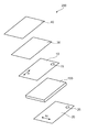
- FIG. 1 is a schematic exploded perspective view of an image display device according to one embodiment of the present invention
- FIG. 2 is a schematic cross-sectional view of a through hole portion of the image display device of FIG.
- the image display device 200 of the illustrated example includes an image display cell 100, a first polarizing plate 10 laminated on the visual side of the image display cell 100, and a second polarizing plate laminated on the back side of the image display cell 100. It has 20 and a third pressure-sensitive adhesive layer 30 arranged on the visible side of the first polarizing plate 10.
- the image display device 200 may further have a cover glass 40 on the visible side of the third pressure-sensitive adhesive layer 30.
- the cover glass 40 may be attached to the first polarizing plate 10 via the third pressure-sensitive adhesive layer 30.
- the first polarizing plate 10 includes a first polarizing element 11, a protective layer (outer protective layer) 12 arranged on the visual side of the first polarizing element 11, and an image display cell 100 of the first polarizing element 11. It has a protective layer (inner protective layer) 13 arranged on the side and a first adhesive layer 14 arranged as an outermost layer on the image display cell side.
- the first polarizing plate 10 is laminated on the image display cell 100 via the first pressure-sensitive adhesive layer 14.
- One of the protective layers 12 and 13 may be omitted depending on the purpose and the like.
- the second polarizing plate 20 includes a second polarizing element 21, a protective layer (outer protective layer) 22 arranged on the back side of the second polarizing element 21, and an image display cell 100 of the second polarizing element 21. It has a protective layer (inner protective layer) 23 arranged on the side and a second adhesive layer 24 arranged as an outermost layer on the image display cell side.
- the second polarizing plate 20 is laminated on the image display cell 100 via the second pressure-sensitive adhesive layer 24.
- One of the protective layers 22 and 23 may be omitted depending on the purpose and the like.
- the first polarizing plate 10 and second polarizing plate 20, the absorption axis A 1 of the first polarizer 11 and the absorption axis A 2 of the second polarizer 21 are substantially perpendicular It is arranged in this way.
- a 1 is described in the longitudinal direction and A 2 is described in the lateral direction, but these may be reversed.
- substantially orthogonal includes the case where the angle formed by two directions is 90 ° ⁇ 7 °, preferably 90 ° ⁇ 5 °, and more preferably 90 ° ⁇ . It is 3 °.
- substantially parallel includes the case where the angle formed by the two directions is 0 ° ⁇ 7 °, preferably 0 ° ⁇ 5 °, and more preferably 0 ° ⁇ 3 °.
- orthogonal or parallel in the present specification includes the case of “substantially orthogonal” or “substantially parallel”. Further, when referring to an angle herein, it includes both clockwise and counterclockwise with respect to the reference direction.
- the first polarizing plate 10 has a deformed processing portion 15, and the second polarizing plate 20 has a deformed processing portion 25.
- the first polarizing plate 10 and the second polarizing plate 20 have deformed processing portions 15 and 25 at positions corresponding to each other.
- the deformed portion 15 of the first polarizing plate 10 is typically filled with a pressure-sensitive adhesive constituting the third pressure-sensitive adhesive layer 30.
- "provided at positions corresponding to each other” means that the deformed portions overlap when the two polarizing plates are overlapped.
- the "deformed portion” refers to a portion processed into a special shape different from a general shape (for example, a rectangle or chamfering of a corner). As shown in FIGS.
- typical examples of the deformed portion include a through hole and a machined portion that becomes a recess when viewed in a plan view.
- Typical examples of the recess include a shape similar to a ship shape, a V-shaped notch, and a U-shaped notch.
- the first polarizing plate and the second polarizing plate may be entirely deformed.
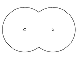
- FIGS. 5 and 6 there is a shape corresponding to the instrument panel of an automobile.
- the shape includes a portion in which the outer edge is formed in an arc shape along the rotation direction of the meter needle and the outer edge is V-shaped (including a round shape) convex inward in the plane direction.
- the deformed portion is provided at an arbitrary appropriate position according to the purpose.
- the deformed portion is provided at or near the end of each polarizing plate.
- the deformed portion may be provided at a substantially central portion of the longitudinal end portion of the rectangular polarizing plate, or may be provided at a predetermined position at the longitudinal end portion, and may be polarized. It may be provided at the corner of the board.
- the deformed portion may be provided at the end portion in the longitudinal direction, but the deformed portion may be provided at the end portion in the lateral direction.
- a plurality of deformed processing portions may be provided.
- two or more through holes may be provided, a through hole and a notch may be provided in combination, or two or more notches may be provided (not shown).
- the image display device includes an image display panel.
- the image display panel includes an image display cell.
- the image display device may be referred to as an optical display device.
- the image display panel may be referred to as an optical display panel.
- the image display cell may be referred to as an optical display cell.
- Typical examples of the image display cell 100 include a liquid crystal cell, an organic electroluminescence (EL) cell, and a quantum dot cell. Therefore, typical examples of the image display device 200 include a liquid crystal display device, an organic EL display device, and a quantum dot display device.
- the illustrated example typically shows the configuration of a liquid crystal display device. In the liquid crystal display device, the effect of the combination of the first polarizing plate and the second polarizing plate becomes remarkable. In the organic EL display device, the second polarizing plate 20 may be omitted.
- the image display device 200 has a camera unit (not shown) at a position corresponding to the deformed processing units 15 and 25.
- the pressure-sensitive adhesive constituting the third pressure-sensitive adhesive layer 30 has a storage elastic modulus at 60 ° C. when the third pressure-sensitive adhesive layer 30 is laminated on the first polarizing plate 10. It is 0.0 ⁇ 10 4 Pa to 1.0 ⁇ 10 5 Pa.
- the pressure-sensitive adhesive constituting the third pressure-sensitive adhesive layer any suitable pressure-sensitive adhesive can be used as long as it has such a storage elastic modulus at the time of lamination.
- the pressure-sensitive adhesive may be a photocurable pressure-sensitive adhesive or a non-curable pressure-sensitive adhesive.
- the "photocurable pressure-sensitive adhesive" refers to a pressure-sensitive adhesive whose cross-linking reaction proceeds by irradiation with light.
- the photocurable pressure-sensitive adhesive is soft and has excellent deformability at the time of lamination, and can be imparted with desired properties (for example, storage elastic modulus) as the pressure-sensitive adhesive layer by irradiating light after the lamination.
- desired properties for example, storage elastic modulus
- the photocurable pressure-sensitive adhesive is extremely excellent in filling property of the deformed processed portion, and the thickness of the third pressure-sensitive adhesive layer (as a result, the image display device) can be reduced. Further, even when a thick frame printing layer is formed on the cover glass, for example, good adhesiveness can be ensured.
- the "non-curable pressure-sensitive adhesive” refers to a pressure-sensitive adhesive in which the cross-linking reaction is substantially completed and the cross-linking reaction does not substantially proceed after lamination.
- the non-curable pressure-sensitive adhesive can be a so-called ordinary pressure-sensitive adhesive.
- the non-curable adhesive is excellent in productivity because it does not require light irradiation (photo-curing), and further, it is possible to prevent the occurrence of dents, the adhesive squeezing out from the end of the punched product, and poor handling. it can.
- the storage elastic modulus at 60 ° C. before curing of the photocurable pressure-sensitive adhesive can substantially correspond to the storage elastic modulus at the time of laminating.
- the storage elastic modulus before curing is 1.0 ⁇ 10 5 Pa or less, preferably 1.0 ⁇ 10 3 Pa to 1.0 ⁇ 10 5 Pa, as described above.
- the storage elastic modulus of the photocurable pressure-sensitive adhesive at 60 ° C. after curing is preferably 5.0 ⁇ 10 3 Pa to 5.0 ⁇ 10 5 Pa.
- the gel fraction of the photocurable pressure-sensitive adhesive before curing is 0% to 60%, and the gel fraction after curing is 50% to 95%.
- the thickness of the third pressure-sensitive adhesive layer is preferably 50 ⁇ m to 500 ⁇ m, more preferably 75 ⁇ m to 475 ⁇ m, and further preferably 100 ⁇ m to 100 ⁇ m. It is 450 ⁇ m.
- the storage elastic modulus at 60 ° C. when the non-curable pressure-sensitive adhesive is laminated is preferably 1.0 ⁇ 10 3 Pa to 8.0 ⁇ 10 4 Pa, and more preferably 5.0 ⁇ 10 3 Pa to 6. It is 0 ⁇ 10 4 Pa.
- the thickness of the third pressure-sensitive adhesive layer is preferably 50 ⁇ m to 1000 ⁇ m, more preferably 75 ⁇ m to 900 ⁇ m, and further preferably 100 ⁇ m to 100 ⁇ m. It is 800 ⁇ m.
- the dimensional shrinkage ratio in the absorption axis direction of the first polarizing element when the first polarizing plate 10 is heat-treated at 85 ° C. for 24 hours (in the present specification, the heating dimensional shrinkage rate).
- the absolute value of) is 0.7% or less, preferably 0.6% or less, more preferably 0.5% or less, still more preferably 0.4% or less. Particularly preferably, it is 0.3% or less.
- the heating dimensional shrinkage rate is typically a negative value.
- the thickness of the first polarizing element 11 in such a first polarizing plate is preferably less than 10 ⁇ m, more preferably 8 ⁇ m or less, still more preferably 6 ⁇ m or less, and particularly. It is preferably 5 ⁇ m or less.
- the lower limit of the thickness can be, for example, 1 ⁇ m.
- the first polarizer 11 has a thickness of preferably 10 ⁇ m to 20 ⁇ m, more preferably 12 ⁇ m to 18 ⁇ m.
- the thickness of the first polarizing plate 10 is preferably 100 ⁇ m or less, more preferably 80 ⁇ m or less, and further preferably 60 ⁇ m or less.
- the lower limit of the thickness can be, for example, 40 ⁇ m.
- the first polarizing plate (substantially, the first polarizing element) is preferably heat-shrinked.
- the heat shrinkage treatment can be performed, for example, at 60 ° C. for 12 hours.
- the thickness of the first polarizing plate includes the thickness of the adhesive that adheres the polarizer and the protective layer, and does not include the thickness of the first pressure-sensitive adhesive layer.
- the third pressure-sensitive adhesive layer and the first polarizing plate As described above, air bubbles can be remarkably suppressed in an image display device in which the deformed portion is filled with the pressure-sensitive adhesive. In particular, the generation of bubbles, so-called delay bubbles, can be remarkably suppressed.
- the details are as follows. Filling with the pressure-sensitive adhesive constituting the third pressure-sensitive adhesive layer of the deformed portion is typically performed by vacuum laminating a laminate of a cover glass and a pressure-sensitive adhesive sheet forming the third pressure-sensitive adhesive layer. This is done by bonding to a polarizing plate. Immediately after vacuum laminating, there are often no recognizable bubbles in the filled portion, but bubbles may be generated in the subsequent heating durability test of the image display device.
- Such bubbles can typically be generated by applying shrinkage stress of the polarizing plate to the filled portion.
- Such bubbles are called delay bubbles.
- the delay bubble is not a fine one, but a large one that occupies a certain percentage or more of the plan view area of the deformed portion, and from the viewpoint of appearance, the camera performance of the camera portion provided at the position corresponding to the deformed portion Is also unacceptable.
- the desired heat dimensional shrinkage rate (absolute value) can be realized without performing the heat shrinkage treatment. Therefore, by omitting the heat shrinkage treatment, not only the productivity can be increased, but also the dimensional change and the occurrence of curl can be prevented. Further, by reducing the thickness of the first polarizing element (first polarizing plate) and forming the third pressure-sensitive adhesive layer with a non-curable pressure-sensitive adhesive, the heat shrinkage treatment can be omitted and the light can be omitted. Since irradiation (photocuring) can be omitted, productivity can be further increased.
- the size of the deformed portion is small (for example,).
- the diameter of the through hole is small, the depth and angle of the V-shaped notch are small, the depth and radius of curvature of the U-shaped notch are small), and / or when multiple through holes are formed in close proximity. Even if there is, the delay bubble can be remarkably suppressed.
- the end face of the first pressure-sensitive adhesive layer 14 is a first polarizing plate (substantially, a polarizing element).
- 11 or, if present, has an adhesive gap 16 formed located inward in the plane direction with respect to the end surface of the inner protective layer 13).
- the size L of the pressure-sensitive adhesive gap is preferably 300 ⁇ m or less, more preferably 200 ⁇ m or less, further preferably 150 ⁇ m or less, particularly preferably 100 ⁇ m or less, and particularly preferably 80 ⁇ m or less.
- the lower limit of the size L of the pressure-sensitive adhesive gap portion may be, for example, 10 ⁇ m.
- the “size L of the pressure-sensitive adhesive gap” is defined from the end face of the first polarizing plate (substantially, the polarizer 11 or the inner protective layer 13 if present) to the end face of the pressure-sensitive adhesive layer 14. The maximum length up to.
- the image display device 200 may have a backlight unit (not shown) depending on the configuration of the image display cell 100. Since a configuration well known in the art can be adopted for the backlight unit, detailed description thereof will be omitted.
- the image display device 200 may be provided with a retardation layer (not shown).
- the type, number, combination, arrangement position, and characteristics of the retardation layer can be appropriately set according to the purpose.
- the retardation layer may be a ⁇ / 2 plate, a ⁇ / 4 plate, or a laminate thereof.
- the ⁇ / 2 plate and the ⁇ / 4 plate typically have a refractive index characteristic of nx> ny ⁇ nz.
- the in-plane retardation Re (550) is preferably 180 nm to 320 nm for the ⁇ / 2 plate, and the in-plane retardation Re (550) is preferably 100 nm to 200 nm for the ⁇ / 4 plate.
- Re ( ⁇ ) is an in-plane phase difference measured with light having a wavelength of ⁇ nm at 23 ° C.
- Re (550) is an in-plane phase difference measured with light having a wavelength of 550 nm at 23 ° C.
- Rth ( ⁇ ) is a phase difference in the thickness direction measured with light having a wavelength of ⁇ nm at 23 ° C.
- Rth (550) is a phase difference in the thickness direction measured with light having a wavelength of 550 nm at 23 ° C.
- Nx is the refractive index in the direction in which the in-plane refractive index is maximized (that is, the slow-phase axis direction), and "ny” is the in-plane direction orthogonal to the slow-phase axis (that is, the phase-advance axis direction). Is the refractive index of, and "nz” is the refractive index in the thickness direction.
- the image display device 200 may be provided with an optical member (not shown).
- the type, number, combination, arrangement position, and characteristics of the optical members can be appropriately set according to the purpose.
- a reflective polarizer, a prism sheet, and / or a diffuser plate may be provided on the back surface side of the second polarizing plate.
- the reflective polarizer may also serve as the outer protective layer of the second polarizing plate.
- the components of the image display device will be specifically described.
- the first polarizing plate and the second polarizing plate are collectively referred to as a polarizing plate
- the first and second polarizing elements are collectively referred to as a polarizer.
- the respective protective layers will be collectively described as a protective layer
- the first pressure-sensitive adhesive layer and the second pressure-sensitive adhesive layer will be collectively described as a pressure-sensitive adhesive layer. Therefore, for example, when the term "polarizing plate is” means "the first polarizing plate and the second polarizing plate are each".
- the polarizer is typically composed of a resin film containing a dichroic substance.
- the resin film any suitable resin film that can be used as a polarizer can be adopted.
- the resin film is typically a polyvinyl alcohol-based resin (hereinafter referred to as "PVA-based resin") film.
- the resin film may be a single-layer resin film or a laminated body having two or more layers.
- the polarizer composed of a single-layer resin film include those obtained by subjecting a PVA-based resin film to a dyeing treatment with iodine and a stretching treatment (typically, uniaxial stretching).
- the dyeing with iodine is performed, for example, by immersing a PVA-based film in an aqueous iodine solution.
- the draw ratio of the uniaxial stretching is preferably 3 to 7 times. Stretching may be performed after the dyeing treatment or while dyeing. Alternatively, it may be stretched and then dyed. If necessary, the PVA-based resin film is subjected to a swelling treatment, a cross-linking treatment, a cleaning treatment, a drying treatment and the like.
- the polarizer obtained by using the laminate include a laminate of a resin base material and a PVA-based resin layer (PVA-based resin film) laminated on the resin base material, or a resin base material and the resin.
- Examples thereof include a polarizer obtained by using a laminate with a PVA-based resin layer coated and formed on a base material.
- the polarizer obtained by using the laminate of the resin base material and the PVA-based resin layer coated and formed on the resin base material is, for example, a resin base material obtained by applying a PVA-based resin solution to the resin base material and drying the resin base material.
- stretching typically includes immersing the laminate in an aqueous boric acid solution for stretching. Further, stretching may further include, if necessary, stretching the laminate in the air at a high temperature (eg, 95 ° C. or higher) prior to stretching in boric acid aqueous solution.
- a high temperature eg, 95 ° C. or higher
- the obtained resin base material / polarizer laminate may be used as it is (that is, the resin base material may be used as a protective layer for the polarizer), and the resin base material is peeled off from the resin base material / polarizer laminate. Then, an arbitrary appropriate protective layer according to the purpose may be laminated on the peeled surface. Details of the method for producing such a polarizer are described in, for example, Japanese Patent Application Laid-Open No. 2012-73580 and Japanese Patent No. 6470455. The entire description of the publication is incorporated herein by reference.
- the thickness of the first polarizer is as described in Section A above.
- the thickness of the second polarizer can be appropriately set according to the purpose.
- the thickness of the second polarizer is preferably 1 ⁇ m to 30 ⁇ m, more preferably 2 ⁇ m to 15 ⁇ m, and even more preferably 1 ⁇ m to 10 ⁇ m.
- the thickness of the second polarizer is in such a range, curling during heating can be satisfactorily suppressed, and good appearance durability during heating can be obtained.
- the polarizer preferably exhibits absorption dichroism at any wavelength of 380 nm to 780 nm.
- the simple substance transmittance of the polarizer is, for example, 41.5% to 46.0%, preferably 43.0% to 46.0%, and more preferably 44.5% to 46.0%.
- the degree of polarization of the polarizer is preferably 97.0% or more, more preferably 99.0% or more, and further preferably 99.9% or more.
- the protective layer is formed of any suitable film that can be used as a protective layer for the polarizer.
- the material that is the main component of the film include cellulose-based resins such as triacetyl cellulose (TAC), polyester-based, polyvinyl alcohol-based, polycarbonate-based, polyamide-based, polyimide-based, polyethersulfone-based, and polysulfone-based. , Polystyrene-based, polycarbonate-based, polyolefin-based, (meth) acrylic-based, acetate-based transparent resins and the like.
- TAC triacetyl cellulose
- polyester-based polyvinyl alcohol-based
- polycarbonate-based polycarbonate-based
- polyamide-based polyamide-based
- polyimide-based polyimide-based
- polyethersulfone-based polysulfone-based
- thermosetting resins such as (meth) acrylic, urethane, (meth) acrylic urethane, epoxy, and silicone, or ultraviolet curable resins can also be mentioned.
- glassy polymers such as siloxane-based polymers can also be mentioned.
- the polymer film described in JP-A-2001-343529 (WO01 / 37007) can also be used.
- a resin composition containing a thermoplastic resin having a substituted or unsubstituted imide group in the side chain and a thermoplastic resin having a substituted or unsubstituted phenyl group and a nitrile group in the side chain.
- the polymer film can be, for example, an extruded product of the above resin composition.
- the outer protective layer (particularly, the outer protective layer 12 of the first polarizing plate) may be subjected to surface treatment such as hard coating treatment, antireflection treatment, anti-sticking treatment, anti-glare treatment, etc., if necessary. ..
- the inner protective layer is preferably optically isotropic.
- optically isotropic means that the in-plane retardation Re (550) is 0 nm to 10 nm and the thickness direction retardation Rth (550) is -10 nm to +10 nm.
- the thickness of the protective layer is, for example, 15 ⁇ m to 45 ⁇ m, preferably 20 ⁇ m to 40 ⁇ m.
- the thickness of the protective layer is the thickness including the thickness of the surface treatment layer.
- the adhesive layer is typically used to attach each polarizing plate to an image display cell.
- the pressure-sensitive adhesive layer may be typically composed of an acrylic pressure-sensitive adhesive (acrylic pressure-sensitive adhesive composition).
- the acrylic pressure-sensitive adhesive composition typically contains a (meth) acrylic polymer as a base polymer.
- the (meth) acrylic polymer can be contained in the pressure-sensitive adhesive composition in a proportion of, for example, 50% by weight or more, preferably 70% by weight or more, and more preferably 90% by weight or more in the solid content of the pressure-sensitive adhesive composition.
- the (meth) acrylic polymer contains an alkyl (meth) acrylate as a main component as a monomer unit.
- (meth) acrylate means acrylate and / or methacrylate.
- the alkyl (meth) acrylate can be contained in a proportion of preferably 70% by weight or more, more preferably 80% by weight or more, in the monomer component forming the (meth) acrylic polymer.
- Examples of the alkyl group of the alkyl (meth) acrylate include a linear or branched alkyl group having 1 to 18 carbon atoms. The average number of carbon atoms of the alkyl group is preferably 3 to 9, and more preferably 3 to 6.
- Specific examples of the alkyl (meth) acrylate include methyl acrylate, methyl methacrylate, butyl acrylate, and 2-ethylhexyl acrylate.
- Examples of the monomer (copolymerization monomer) constituting the (meth) acrylic polymer include a carboxyl group-containing monomer, a hydroxyl group-containing monomer, an amide group-containing monomer, a polyfunctional (meth) acrylate, and an aromatic ring, in addition to the alkyl (meth) acrylate. Examples thereof include contained (meth) acrylates and heterocyclic-containing vinyl-based monomers.
- Representative examples of the copolymerization monomer include acrylate, 2-hydroxyethyl acrylate, 4-hydroxybutyl acrylate, phenoxyethyl acrylate, N-vinyl-2-pyrrolidone, and N-acryloylmorpholine.
- the acrylic pressure-sensitive adhesive composition may preferably contain a silane coupling agent and / or a cross-linking agent.
- the silane coupling agent include an epoxy group-containing silane coupling agent.
- the cross-linking agent include isocyanate-based cross-linking agents and peroxide-based cross-linking agents.
- the acrylic pressure-sensitive adhesive composition may contain an additive. Specific examples of additives include antioxidants, antistatic agents, rework improvers, colorants, pigments, dyes, surfactants, plasticizers, tackifiers, surface lubricants, leveling agents, softeners, and aging.
- Examples include inhibitors, light stabilizers, UV absorbers, polymerization inhibitors, conductive agents, inorganic or organic fillers, metal powders, particulates and foils. Further, a redox system to which a reducing agent is added may be adopted within a controllable range.
- the type, number, combination, blending amount, etc. of the additive can be appropriately set according to the purpose. By appropriately adjusting the types, combinations, blending amounts, etc. of the monomer components, and the types, numbers, combinations, blending amounts, etc. of the cross-linking agents, silane coupling agents, and additives, the desired properties can be obtained according to the purpose.
- An acrylic pressure-sensitive adhesive composition (as a result, a pressure-sensitive adhesive layer) can be obtained.
- the thickness of the pressure-sensitive adhesive layer is preferably 50 ⁇ m or less, more preferably 40 ⁇ m or less, further preferably 30 ⁇ m or less, and particularly preferably 25 ⁇ m or less.
- the lower limit of the thickness of the pressure-sensitive adhesive layer can be, for example, 2 ⁇ m. If the thickness of the pressure-sensitive adhesive layer is within such a range, it can contribute to the thinning of the image display device. In particular, when the thickness of the first pressure-sensitive adhesive layer is within such a range, it becomes easy to fill the deformed portion with the pressure-sensitive adhesive constituting the third pressure-sensitive adhesive layer. More specifically, since the depth of the deformed portion becomes smaller, it becomes easier to be filled with the adhesive.
- the gap in the deformed portion becomes smaller, so that bubbles are less likely to be generated due to deformation of the adhesive or the like.
- the thickness of the first pressure-sensitive adhesive layer is in such a range, it can contribute to the suppression of delay bubbles.
- the adhesive strength between the pressure-sensitive adhesive constituting the pressure-sensitive adhesive layer (particularly, the first pressure-sensitive adhesive layer) and the pressure-sensitive adhesive constituting the third pressure-sensitive adhesive layer is preferably 2N / 25 mm or more, more preferably 5N /. It is 25 mm or more, more preferably 10 N / 25 mm or more.
- the upper limit of the adhesive force can be, for example, 50 N / 25 mm.
- the first pressure-sensitive adhesive layer and the third pressure-sensitive adhesive layer can come into contact with each other. It becomes difficult to peel off from the third adhesive layer. As a result, gaps are less likely to be formed in the deformed portion, and delay bubbles can be suppressed.
- the adhesive strength can be measured according to the "90 degree peel strength test" of JIS Z 0237.
- the elastic modulus of the pressure-sensitive adhesive layer at 85 ° C. is preferably 5.0 ⁇ 10 4 Pa or more, and more preferably 1.0 ⁇ 10 5 Pa or more.
- the upper limit of the elastic modulus of the adhesive layer may be, for example, 1.0 ⁇ 10 6 Pa.
- the elastic modulus of the pressure-sensitive adhesive layer is within such a range, the absolute value of the dimensional shrinkage ratio of the polarizing plate can be reduced.
- the elastic modulus of the first pressure-sensitive adhesive layer is within such a range, the dimensional shrinkage of the first polarizing plate can be suppressed by the synergistic effect with the third pressure-sensitive adhesive layer.
- the third pressure-sensitive adhesive layer 30 is composed of a pressure-sensitive adhesive having a predetermined storage elastic modulus at the time of lamination as described in the above item A, and the pressure-sensitive adhesive is processed into a deformed shape of the first polarizing plate 10. The portion 15 can be filled. First, the characteristics of the third pressure-sensitive adhesive layer and the photocurable pressure-sensitive adhesive constituting the third pressure-sensitive adhesive layer will be described, and then the non-curable pressure-sensitive adhesive will be briefly described.
- the glass transition temperature of the third pressure-sensitive adhesive layer is preferably -3 ° C. or lower, more preferably ⁇ 5 ° C. or lower, still more preferably ⁇ 6 ° C. or lower.
- the glass transition temperature is preferably ⁇ 20 ° C. or higher, more preferably ⁇ 15 ° C. or higher, and even more preferably ⁇ 13 ° C. or higher.
- the peak top value of the loss tangent tan ⁇ of the third pressure-sensitive adhesive layer is preferably 1.5 or more, more preferably 1.6 or more, and further preferably 1.7.
- the above is particularly preferable, and it is 1.75 or more.
- the upper limit of the peak top value of tan ⁇ is preferably 3.0 or less, more preferably 2.5 or less, and further preferably 2.3 or less.
- the total light transmittance of the third pressure-sensitive adhesive layer is preferably 85% or more, more preferably 90% or more.
- the haze value of the third pressure-sensitive adhesive layer is preferably 1.5% or less, more preferably 1.0% or less.
- the storage elastic modulus of the photocurable adhesive at 60 ° C. before curing is 1.0 ⁇ 10 5 Pa or less, preferably 1.0 ⁇ 10 3 Pa to 1. It is 0 ⁇ 10 5 Pa, more preferably 5.0 ⁇ 10 3 Pa to 8.0 ⁇ 10 4 Pa, and even more preferably 7.5 ⁇ 10 3 Pa to 6.0 ⁇ 10 4 Pa. If the storage elastic modulus of the photocurable pressure-sensitive adhesive before curing is within such a range, the photo-curable pressure-sensitive adhesive exhibits appropriate deformation behavior (viscoelastic behavior) and flows well into every corner of the deformed processed portion. obtain.
- the storage elastic modulus of the photocurable pressure-sensitive adhesive at 60 ° C. after curing is preferably 5.0 ⁇ 10 3 Pa to 5.0 ⁇ 10 5 Pa, and more preferably 7.5 ⁇ 10 3 Pa to 4. It is 0 ⁇ 10 5 Pa, more preferably 8.0 ⁇ 10 3 Pa to 3.0 ⁇ 10 5 Pa.
- the storage elastic modulus of the photocurable pressure-sensitive adhesive after curing is within such a range, the gel elasticity of the third pressure-sensitive adhesive becomes low and the residual stress becomes small. As a result, the delay bubble can be suppressed.
- the gel fraction of the photocurable pressure-sensitive adhesive before curing is preferably 0% to 60%, more preferably 0% to 55%, and even more preferably 0% to 50%.
- the photocurable pressure-sensitive adhesive exhibits appropriate deformation behavior (viscoelastic behavior) and can flow into every corner of the deformed portion satisfactorily. As a result, gaps are less likely to be formed in the deformed portion, and delay bubbles can be suppressed.
- the gel fraction of the photocurable pressure-sensitive adhesive after curing is preferably 50% to 95%, more preferably 55% to 93%, and even more preferably 60% to 90%.
- the gel fraction after curing of the photocurable pressure-sensitive adhesive is within such a range, the cover glass, the first polarizing plate, and the image display cell can be firmly fixed. As a result, the delay bubble can be suppressed.
- the gel fraction can be determined as an insoluble component in a solvent such as ethyl acetate. Specifically, the gel fraction is the weight fraction (unit: weight%) of the insoluble component after immersing the pressure-sensitive adhesive constituting the pressure-sensitive adhesive layer in ethyl acetate at 23 ° C. for 7 days with respect to the sample before immersion. Is required as.
- the gel fraction can be adjusted by appropriately setting the type, combination and blending amount of the monomer components constituting the base polymer of the pressure-sensitive adhesive, and the type and blending amount of the cross-linking agent.
- any suitable photocurable adhesive in this section, it may be simply referred to as a pressure-sensitive adhesive composition) as long as it has the above-mentioned properties. There is) can be used.
- the base polymer of the pressure-sensitive adhesive composition include (meth) acrylic polymers, silicone-based polymers, polyesters, polyurethanes, polyamides, polyvinyl ethers, vinyl acetate / vinyl chloride copolymers, modified polyolefins, epoxy-based polymers, and fluoropolymers.
- examples include rubber-based polymers such as natural rubber and synthetic rubber.
- (meth) acrylic pressure-sensitive adhesive composition containing a (meth) acrylic polymer as a base polymer.
- a (meth) acrylic polymer as a base polymer.
- (meth) acrylic means acrylic and / or methacryl.
- the (meth) acrylic base polymer (hereinafter, may be simply referred to as a base polymer) preferably has a crosslinked structure.
- the (meth) acrylic base polymer contains an alkyl (meth) acrylate as a main monomer component.
- an alkyl (meth) acrylate having an alkyl group having 1 to 20 carbon atoms is preferably used.
- the alkyl (meth) acrylate may have a branched alkyl group or a cyclic alkyl group.
- the amount of alkyl (meth) acrylate with respect to the total amount of the monomer components constituting the (meth) acrylic base polymer is preferably 40% by weight or more, more preferably 50% by weight or more, still more preferably 60% by weight or more. is there.
- the alkyl (meth) acrylate having a chain alkyl group having 4 to 10 carbon atoms with respect to the total amount of the monomer components constituting the (meth) acrylic base polymer is preferably 30% by weight or more, more preferably 40% by weight or more, and further preferably 45% by weight or more.
- the (meth) acrylic-based base polymer preferably contains a monomer component having a crosslinkable functional group.
- the gel fraction of the pressure-sensitive adhesive can be adjusted to a desired range.
- the monomer component having a crosslinkable functional group include a hydroxyl group-containing monomer and a carboxy group-containing monomer.
- a hydroxyl group-containing monomer is used as a monomer component having a crosslinkable functional group, and a crosslinked structure can be introduced by an isocyanate-based crosslinking agent.
- a crosslinked structure can be introduced by an isocyanate-based crosslinking agent.
- the amount of the hydroxyl group-containing monomer is preferably 5% by weight to 30% by weight, more preferably 8% by weight to 25% by weight, still more preferably 10% by weight, based on the total amount of the monomer components constituting the (meth) acrylic base polymer. It is from% by weight to 20% by weight.
- the amount of the hydroxyl group-containing monomer is within such a range, the degree of cross-linking (gel fraction) can be increased with a small amount of the cross-linking agent, and as a result, the filling property of the photocurable pressure-sensitive adhesive before curing and the filling property of the deformed processed portion and Operability can be improved. Furthermore, since unreacted hydroxyl groups can form intermolecular hydrogen bonds after cross-linking, a desired storage elastic modulus can be achieved even if the gel fraction is small.
- the third pressure-sensitive adhesive layer When the third pressure-sensitive adhesive layer can come into contact with the touch panel sensor, for example, the third pressure-sensitive adhesive layer preferably has a small acid content in order to prevent corrosion of the electrode due to the acid component.
- the amount of the carboxy group-containing monomer with respect to the total amount of the monomer components constituting the (meth) acrylic base polymer is preferably 0.5% by weight or less, more preferably 0.1% by weight or less, and further preferably. Is 0.05% by weight or less, ideally 0 (zero).
- the acid content in the photocurable pressure-sensitive adhesive can be preferably 100 ppm or less, more preferably 70 ppm or less, still more preferably 50 ppm or less.
- the (meth) acrylic-based base polymer may contain a nitrogen-containing monomer as a monomer component.
- a highly polar monomer such as a hydroxyl group-containing monomer, a carboxy group-containing monomer, and a nitrogen-containing monomer as a monomer component
- the (meth) acrylic-based base polymer has a storage elasticity, adhesive retention, and impact resistance.
- a well-balanced third pressure-sensitive adhesive layer can be formed.
- the amount of highly polar monomer (total of hydroxyl group-containing monomer, carboxy group-containing monomer and nitrogen-containing monomer) with respect to the total amount of the monomer components constituting the (meth) acrylic base polymer is preferably 10% by weight to 45% by weight, more preferably.
- the amount of the nitrogen-containing monomer with respect to the total amount of the monomer components constituting the (meth) acrylic base polymer is preferably 3% by weight to 25% by weight, more preferably 5% by weight to 20% by weight, still more preferably 7. It is from% by weight to 15% by weight.
- the (meth) acrylic polymer may further contain any suitable monomer component depending on the purpose.
- a monomer component include an acid anhydride group-containing monomer, a caprolactone additive of (meth) acrylic acid, a sulfonic acid group-containing monomer, a phosphoric acid group-containing monomer, vinyl acetate, vinyl propionate, styrene, and ⁇ -.
- Vinyl-based monomers such as methylstyrene; cyano group-containing acrylic monomers such as acrylonitrile and methacrylonitrile; epoxy group-containing monomers such as glycidyl (meth) acrylate; polyethylene glycol (meth) acrylate, polypropylene glycol (meth) acrylate.
- Glycol-based acrylic ester monomers such as (meth) methoxyethylene glycol (meth) acrylate, (meth) methoxypolypropylene glycol (meth) acrylate, tetrahydrofurfuryl (meth) acrylate, fluorine (meth) acrylate, silicone (meth) acrylate, (meth) Examples thereof include acrylic acid ester-based monomers such as 2-methoxyethyl acrylate.
- the (meth) acrylic-based base polymer preferably contains the most alkyl (meth) acrylate as a monomer component, and more preferably contains the most alkyl (meth) acrylate having a chain alkyl group having 6 or less carbon atoms. With such a configuration, the peak top value of tan ⁇ becomes large, and the impact resistance can be improved.
- the amount of the alkyl (meth) acrylate having a chain alkyl group having 6 or less carbon atoms with respect to the total amount of the monomer components constituting the (meth) acrylic base polymer is preferably 30% by weight to 80% by weight, more preferably 35. It is from% by weight to 75% by weight, more preferably 40% by weight to 70% by weight. In particular, the content of butyl acrylate as a monomer component is preferably in the above range.
- the glass transition temperature (Tg) of the (meth) acrylic base polymer is preferably ⁇ 50 ° C. or higher.
- the Tg of the (meth) acrylic base polymer is preferably ⁇ 5 ° C. or lower, more preferably ⁇ 10 ° C. or lower, and further preferably ⁇ 15 ° C. or lower.
- Crosslinked structure For a polymer in which a crosslinked structure is introduced into a (meth) acrylic base polymer, for example, (1) a (meth) acrylic polymer having a functional group capable of reacting with a crosslinking agent is polymerized, and then a crosslinking agent is added. , A method of reacting a (meth) acrylic polymer with a cross-linking agent; and (2) a method of introducing a branched structure (cross-linked structure) into a polymer chain by including a polyfunctional compound in the polymer component of the polymer, etc. Obtained by These may be used together.
- cross-linking agent in the method of reacting the base polymer of the above (1) with the cross-linking agent include an isocyanate-based cross-linking agent, an epoxy-based cross-linking agent, an oxazoline-based cross-linking agent, an aziridine-based cross-linking agent, a carbodiimide-based cross-linking agent, and a metal.
- examples include a chelate-based cross-linking agent.
- isocyanate-based cross-linking agents and epoxy-based cross-linking agents are preferable because they have high reactivity with the hydroxyl groups and carboxy groups of the base polymer and the cross-linked structure can be easily introduced.
- cross-linking agents react with functional groups such as hydroxyl groups and carboxy groups introduced into the base polymer to form a cross-linked structure.
- functional groups such as hydroxyl groups and carboxy groups introduced into the base polymer.
- the cross-linking agent is preferably 0.03 parts by weight to 0.5 parts by weight, more preferably 0.05 parts by weight to 0.3 parts by weight, still more preferably 0.06 parts by weight, based on 100 parts by weight of the base polymer. It can be used in a proportion of up to 0.25 parts by weight, particularly preferably 0.07 parts by weight to 0.2 parts by weight. By setting the amount of the cross-linking agent used in such a range, the gel fraction can be set in the above-mentioned desired range.
- the total amount of the monomer component constituting the (meth) acrylic base polymer and the polyfunctional compound for introducing the crosslinked structure can be used at once.
- the reaction may be carried out, or the polymerization may be carried out in multiple steps.
- a monofunctional monomer constituting a (meth) acrylic base polymer is polymerized (prepolymerized) to prepare a partial polymer (prepolymer composition), and the prepolymer composition is prepared.
- a method of adding a polyfunctional compound such as a polyfunctional (meth) acrylate to polymerize (mainly polymerize) the prepolymer composition and the polyfunctional monomer is preferable.
- the prepolymer composition is a partial polymer containing a polymer having a low degree of polymerization and an unreacted monomer.
- branch points (crosslink points) due to the polyfunctional compound can be uniformly introduced into the (meth) acrylic base polymer.
- main polymerization is performed on the base material to form a pressure-sensitive adhesive layer. You can also do it.
- low-polymerization compositions such as prepolymer compositions have low viscosity and excellent coatability
- it is a method of performing main polymerization on a substrate after applying a pressure-sensitive adhesive composition which is a mixture of a prepolymer composition and a polyfunctional compound. Therefore, the productivity of the pressure-sensitive adhesive layer can be improved, and the thickness of the pressure-sensitive adhesive layer can be made uniform.
- Examples of the polyfunctional compound used for introducing the crosslinked structure include compounds containing two or more polymerizable functional groups (ethylenically unsaturated groups) having an unsaturated double bond in one molecule.
- the polyfunctional compound is typically a photopolymerizable polyfunctional compound.
- a polyfunctional (meth) acrylate is preferable because it can be easily copolymerized with the monomer component of the (meth) acrylic polymer.
- polyfunctional (meth) acrylate is preferable.
- the molecular weight of the polyfunctional compound is preferably 1500 or less, more preferably 1000 or less.
- the lower limit of the molecular weight can be, for example, 500.
- the functional group equivalent (g / eq) of the polyfunctional compound is preferably 50 to 500, more preferably 70 to 300, and even more preferably 80 to 200. With such a configuration, the viscoelasticity of the photocurable pressure-sensitive adhesive can be appropriately adjusted.
- the polyfunctional compound is preferably 1 part by weight to 6 parts by weight, more preferably 2 parts by weight to 5 parts by weight, and further preferably 2.5 parts by weight to 4 parts by weight with respect to 100 parts by weight of the base polymer. Can be used. If the amount used is too small, the adhesive retention of the photocurable pressure-sensitive adhesive (as a result, the third pressure-sensitive adhesive layer) may be insufficient. If the amount used is too large, the formed third pressure-sensitive adhesive layer may become excessively hard, resulting in insufficient impact resistance. Further, the processability and / or the processed dimensional stability of the photocurable pressure-sensitive adhesive may be insufficient.
- the polyfunctional compound may preferably be a compound containing three or more photopolymerizable functional groups in one molecule, more preferably three photopolymerizable functional groups in one molecule. It can be a (meth) acrylate containing the above.
- a trifunctional or higher functional photopolymerizable compound By using a trifunctional or higher functional photopolymerizable compound, the adhesive retention of the photocurable pressure-sensitive adhesive (as a result, the third pressure-sensitive adhesive layer) can be further enhanced.
- a bifunctional photopolymerizable compound and a trifunctional or higher functional photopolymerizable compound may be used in combination.
- the trifunctional or higher functional photopolymerizable compound is preferably 0.5 parts by weight to 5 parts by weight, more preferably 1 part by weight to 4.5 parts by weight, still more preferably 2 parts by weight, based on 100 parts by weight of the base polymer. It can be used in a proportion of up to 4 parts by weight.
- Adhesive Composition is, in addition to the above-mentioned base polymer, cross-linking agent and polyfunctional compound, a photopolymerization initiator, an oligomer, a silane coupling agent, and an optional according to the purpose. May contain suitable additives.
- the photopolymerization initiator examples include a benzoin ether type photopolymerization initiator, an acetophenone type photopolymerization initiator, an ⁇ -ketol type photopolymerization initiator, an aromatic sulfonyl chloride type photopolymerization initiator, and a photoactive oxime type photopolymerization initiator.
- examples thereof include benzoin-based photopolymerization initiators, benzyl-based photopolymerization initiators, benzophenone-based photopolymerization initiators, ketal-based photopolymerization initiators, thioxanthone-based photopolymerization initiators, and acylphosphine oxide-based photopolymerization initiators.
- the photopolymerization initiator may be used alone or in combination of two or more.
- the content of the photopolymerization initiator in the pressure-sensitive adhesive composition is preferably 0.01 parts by weight to 5 parts by weight, more preferably 0.05 parts by weight to 3 parts by weight, based on 100 parts by weight of the base polymer. is there.
- any suitable oligomer can be used. By using the oligomer, the viscoelasticity (and therefore, the filling property and workability of the deformed processed portion) and the adhesive force of the photocurable pressure-sensitive adhesive can be adjusted.
- the oligomer is preferably a (meth) acrylic oligomer.
- the (meth) acrylic oligomer can have excellent compatibility with the base polymer.
- the weight average molecular weight of the oligomer is preferably about 1000 to 30,000, more preferably 1500 to 10000, and even more preferably 2000 to 8000. When the weight average molecular weight of the oligomer is in such a range, excellent adhesive strength and adhesive retention can be realized.
- the Tg of the oligomer is preferably 20 ° C. or higher, more preferably 50 ° C. or higher, further preferably 80 ° C. or higher, and particularly preferably 100 ° C. or higher.
- the Tg of the oligomer is preferably 200 ° C. or lower, more preferably 180 ° C. or lower, and further preferably 160 ° C. or lower.
- the content of the oligomer in the pressure-sensitive adhesive composition is preferably 0.1 part by weight to 10 parts by weight, and more preferably 0.2 parts by weight to 5 parts by weight with respect to 100 parts by weight of the base polymer.
- the content of the oligomer is in such a range, it is possible to form a third pressure-sensitive adhesive layer having excellent adhesive strength while maintaining good processability and processing dimensional stability of the photocurable pressure-sensitive adhesive. it can.
- any suitable silane coupling agent can be used.
- the adhesive strength of the photocurable pressure-sensitive adhesive can be adjusted.
- the content of the silane coupling agent in the pressure-sensitive adhesive composition is preferably 0.01 parts by weight to 5 parts by weight, more preferably 0.03 parts by weight to 2 parts by weight, based on 100 parts by weight of the base polymer. is there.
- the additives are as described in Section C above with respect to the first and second pressure-sensitive adhesive layers.
- the pressure-sensitive adhesive composition (photocurable pressure-sensitive adhesive) has a thickness corresponding to the thickness of the third pressure-sensitive adhesive layer, and serves as a pressure-sensitive adhesive sheet with release films temporarily attached to both sides. Can be provided.
- Non-curable pressure-sensitive adhesive As the non-curable pressure-sensitive adhesive, any suitable non-curable pressure-sensitive adhesive can be used as long as it has the above-mentioned properties. By appropriately adjusting the types, combinations, blending amounts, etc. of the monomer components, and the types, numbers, combinations, blending amounts, etc. of the cross-linking agent, silane coupling agent, and additive, the above-mentioned desired storage elastic modulus can be obtained. A curable pressure-sensitive adhesive (as a result, a third pressure-sensitive adhesive layer) can be obtained. Examples of the non-curable pressure-sensitive adhesive include the pressure-sensitive adhesive described in item C above with respect to the first and second pressure-sensitive adhesive layers, the pressure-sensitive adhesive described in Japanese Patent Application No. 2019-196942 by the present applicant, and JP-A-2016-94569. Examples thereof include the pressure-sensitive adhesives described in the publication. The description of the application and the gazette is incorporated herein by reference.
- the pressure-sensitive adhesive (adhesive composition) constituting the third pressure-sensitive adhesive layer can be provided as a pressure-sensitive adhesive sheet.
- the pressure-sensitive adhesive sheet may be provided as a set of optical members together with a first polarizing plate (visualizing side polarizing plate). Therefore, such a set of optical members is also included in the embodiments of the present invention.
- the set of optical members may further include a second polarizing plate (backside polarizing plate). That is, in the production of the image display device, the pressure-sensitive adhesive sheet, the first polarizing plate (visualizing side polarizing plate) and the second polarizing plate (back surface side polarizing plate) can be provided as a set of optical members.
- Thickness The thickness of 10 ⁇ m or less was measured using an interference film thickness meter (manufactured by Otsuka Electronics Co., Ltd., product name “MCPD-3000”). The thickness exceeding 10 ⁇ m was measured using a digital micrometer (manufactured by Anritsu, product name “KC-351C”).
- Gel fraction The weight fraction (unit: weight) of the insoluble component after cross-linking the pressure-sensitive adhesive constituting the third pressure-sensitive adhesive layer and immersing it in ethyl acetate at 23 ° C. for 7 days with respect to the sample before immersion. %).
- (3) Storage elastic modulus With respect to the pressure-sensitive adhesive constituting the third pressure-sensitive adhesive layer, the storage elastic modulus at 60 ° C.
- the first polarizing plate (visualizing side polarizing plate) used in Examples and Comparative Examples was cut out to a size of 10 cm ⁇ 10 cm and used as a measurement sample. This measurement sample was heated at 85 ° C. for 24 hours, and the heating dimensional shrinkage rate in the absorption axis direction of the polarizer was determined from the following formula.
- Heated dimension shrinkage rate (%) ⁇ (dimension after heating) / (dimension before heating) -1 ⁇ x 100 (5) Size of Adhesive Void Part Observe with an optical microscope the state of the cross section of the first pressure-sensitive adhesive layer in the deformed portion of the first polarizing plate (visualizing side polarizing plate) used in Examples and Comparative Examples. The length of the portion where the loss of the pressure-sensitive adhesive layer from the outer edge to the inside in the plane direction was maximized was measured, and the size of the pressure-sensitive adhesive gap was L ( ⁇ m).
- Bubbles The image display compatible products obtained in Examples and Comparative Examples were autoclaved (50 ° C / 0.5 MPa / 15 min) after vacuum laminating and UV-cured (illuminance 150 mW / cm 2 and 3000 mJ). At the time of irradiation amount), the state of bubbles was observed visually or by an optical microscope (after vacuum lamination). Then, the sample was further put into a heating test (85 ° C., 24 hours), and when it was taken out, the state of bubbles was observed visually or with an optical microscope (after the heating test), and evaluated according to the following criteria.
- rework improver (trade name: Cyril SAT10, manufactured by Kaneka) 0.03 parts
- antistatic agent (trade name: LiTFSi30EA, manufactured by Mitsubishi Materials) 7 parts
- antioxidant (trade name: Crosslink 1010, hindered phenol type, manufactured by BASF Japan) 0.3 part
- silane coupling agent (trade name: A-100, manufactured by Soken Kagaku Co., Ltd., acetacetyl group) 0.2 part of the contained silane coupling agent) was blended to obtain a pressure-sensitive adhesive composition a.
- ⁇ Manufacturing Example 2 Preparation of a photocurable pressure-sensitive adhesive constituting the third pressure-sensitive adhesive layer> Contains 65 parts of butyl acrylate (BA), 5 parts of cyclohexyl acrylate (CHA), 10 parts of N-vinyl-2-pyrrolidone (NVP), 15 parts of 4-hydroxybutyl acrylate (4HBA) and 5 parts of isostearyl acrylate (ISTA). A mixture of monomers was charged. Further, with respect to 100 parts of the monomer mixture (solid content), 0.2 parts of 2,2'-azobisisobutyronitrile as a polymerization initiator and 0.065 parts of ⁇ -thioglycerol (TGR) as a chain transfer agent were added.
- BA butyl acrylate
- CHP cyclohexyl acrylate
- NDP N-vinyl-2-pyrrolidone
- 4HBA 4-hydroxybutyl acrylate
- ISA isostearyl acrylate
- the mixture was charged with 233 parts by weight of ethyl acetate and stirred for 1 hour in a nitrogen atmosphere at 23 ° C. to perform nitrogen substitution. Then, the reaction was carried out at 56 ° C. for 5 hours, followed by a reaction at 70 ° C. for 3 hours to prepare a solution of an acrylic base polymer. The following post-additional components were added to 100 parts of the base polymer to the solution of the acrylic base polymer obtained above, and the mixture was uniformly mixed to prepare a photocurable pressure-sensitive adhesive b. Storage modulus at 60 ° C. before curing of the photocurable adhesive b is 4.7 ⁇ 10 4 Pa, the storage modulus at 60 ° C. after curing was 1.0 ⁇ 10 5 Pa.
- the gel fraction before curing was 40%, and the gel fraction after curing was 80%.
- Dipentaerythritol hexaacrylate as a polyfunctional compound (photocuring agent): Part 2 Polypropylene glycol diacrylate as a polyfunctional compound (photocuring agent) (trade name: APG400, manufactured by Shin-Nakamura Chemical Industry Co., Ltd., polypropylene glycol # 400 ( n 7) Diacrylate, functional group equivalent 268 g / eq): 3 parts
- Photopolymerization initiator (trade name: Irgacure184, manufactured by BASF): 0.2 parts (preparation of adhesive sheet)
- a photocurable pressure-sensitive adhesive b is applied to a 75 ⁇ m-thick polyethylene terephthalate (PET) film (“Diafoil MRF75” manufactured by Mitsubishi Chemical Corporation) provided with a silicone-based release layer on the surface, and heated at 100 ° C. for 3 minutes. After removing the solvent, the same release
- ⁇ Production Example 3 Preparation of a photocurable pressure-sensitive adhesive constituting the third pressure-sensitive adhesive layer> A solution of an acrylic base polymer was prepared in the same manner as in Production Example 2 except that a monomer mixture containing 90 parts of ethylhexyl acrylate (EHA), 5 parts of acrylamide and 5 parts of hydroxyethyl acrylate (HEA) was used. The following post-additional components were added to 100 parts of the base polymer to the solution of the acrylic base polymer obtained above, and the mixture was uniformly mixed to prepare a photocurable pressure-sensitive adhesive c. The storage elastic modulus of the photocurable pressure-sensitive adhesive c at 60 ° C.
- EHA ethylhexyl acrylate
- HOA hydroxyethyl acrylate
- thermoplastic resin base material an amorphous isophthal copolymer polyethylene terephthalate film (thickness: 100 ⁇ m) having a long shape and a Tg of about 75 ° C. was used. One side of the resin base material was corona-treated. 100 weight of PVA-based resin in which polyvinyl alcohol (degree of polymerization 4200, saponification degree 99.2 mol%) and acetacetyl-modified PVA (manufactured by Nippon Synthetic Chemical Industry Co., Ltd., trade name "Gosefimer Z410”) are mixed at a ratio of 9: 1.
- a PVA aqueous solution (coating liquid).
- the PVA aqueous solution was applied to the corona-treated surface of the resin base material and dried at 60 ° C. to form a PVA-based resin layer having a thickness of 13 ⁇ m to prepare a laminate.
- the obtained laminate was uniaxially stretched at the free end 2.4 times in the longitudinal direction (longitudinal direction) between rolls having different peripheral speeds in an oven at 130 ° C. (aerial auxiliary stretching treatment). Next, the laminate was immersed in an insolubilizing bath at a liquid temperature of 40 ° C.
- HC-TAC film was attached to the surface of the polarizer of the resin substrate / first polarizing element laminate obtained above via an ultraviolet curable adhesive.
- the HC-TAC film is a film in which a hard coat (HC) layer (thickness 7 ⁇ m) is formed on a triacetyl cellulose (TAC) film (thickness 25 ⁇ m), and the TAC film is attached so as to be on the polarizer side. I matched it.
- the resin base material is peeled off, a first pressure-sensitive adhesive layer (thickness 20 ⁇ m) is formed on the peeled surface using the pressure-sensitive adhesive composition a obtained in Production Example 1, and an outer protective layer (HC-TAC film) is formed.
- a polarizing plate having the composition of / first polarizer / first pressure-sensitive adhesive layer was obtained.
- This polarizing plate was punched to a size of 148 mm in length and 70 mm in width, and a through hole having a diameter of 3.9 mm was further formed at a corner. At this time, punching was performed so that the absorption axis direction of the polarizer was in the lateral direction. In this way, the first polarizing plate (visualizing side polarizing plate) A was obtained.
- the heating dimensional shrinkage of the first polarizing plate was ⁇ 0.20%, and the size L of the pressure-sensitive adhesive void was 50 ⁇ m. Further, the elastic modulus of the pressure-sensitive adhesive layer at 85 ° C. was 5.7 ⁇ 10 4 Pa.
- the conditions for vacuum laminating were as follows: warm crimping at 0.2 MPa, 60 ° C. (standby time 90 seconds), followed by vacuum laminating at 100 Pa for 10 seconds. Further, the photocurable adhesive was cured by irradiating ultraviolet rays with an integrated light amount of 3000 mJ / cm 2 from the cover glass side with a metal halide lamp (300 mW / cm 2). After that, an autoclave treatment (50 ° C./0.5 MPa/15 min) was performed. A commercially available polarizing plate with an adhesive layer was attached to the other surface of the glass plate by a conventional method as a second polarizing plate (back surface side polarizing plate). In this way, a product compatible with the image display device was produced. The obtained image display device compatible product was subjected to the evaluation of (6) above. The results are shown in Table 1.
- Example 2 An image display device compatible product was produced in the same manner as in Example 1 except that the size L of the pressure-sensitive adhesive gap portion of the first polarizing plate was set to 100 ⁇ m. The obtained image display device compatible product was subjected to the same evaluation as in Example 1. The results are shown in Table 1.
- Example 3 An image display device compatible product was produced in the same manner as in Example 1 except that the thickness of the first pressure-sensitive adhesive layer was 15 ⁇ m. The obtained image display device compatible product was subjected to the same evaluation as in Example 1. The results are shown in Table 1.
- Example 4 An image display device compatible product was produced in the same manner as in Example 3 except that the size L of the pressure-sensitive adhesive gap portion of the first polarizing plate was set to 100 ⁇ m. The obtained image display device compatible product was subjected to the same evaluation as in Example 1. The results are shown in Table 1.
- Example 5 An image display device compatible product was produced in the same manner as in Example 1 except that the thickness of the first pressure-sensitive adhesive layer was 5 ⁇ m. The obtained image display device compatible product was subjected to the same evaluation as in Example 1. The results are shown in Table 1.
- Example 6 An image display device compatible product was produced in the same manner as in Example 5 except that the size L of the pressure-sensitive adhesive gap portion of the first polarizing plate was set to 100 ⁇ m. The obtained image display device compatible product was subjected to the same evaluation as in Example 1. The results are shown in Table 1.
- Examples 7 to 12 An image display device compatible product was produced in the same manner as in Examples 1 to 6 except that the pressure-sensitive adhesive sheet II of Production Example 3 was used as the third pressure-sensitive adhesive layer. The obtained image display device compatible product was subjected to the same evaluation as in Example 1. The results are shown in Table 1.
- Example 13 As the first polarizer, a film (thickness 12 ⁇ m) obtained by adding iodine to a long polyvinyl alcohol (PVA) -based resin film and uniaxially stretching it in the longitudinal direction (MD direction) was used.
- a triacetyl cellulose (TAC) film (thickness 25 ⁇ m) serving as an outer protective layer and an acrylic resin film (thickness 20 ⁇ m) serving as an inner protective layer are bonded to both sides of the polarizer, and the surface of the inner protective layer is coated with Production Example 1.
- TAC triacetyl cellulose
- the obtained pressure-sensitive adhesive composition a is used to form a first pressure-sensitive adhesive layer (thickness 20 ⁇ m), and the outer protective layer (TAC film) / first polarizer / inner protective layer (COP film) / first.
- a polarizing plate having a structure of a pressure-sensitive adhesive layer was obtained. This polarizing plate was punched in the same manner as in Example 1 to form through holes. In this way, the first polarizing plate (visualizing side polarizing plate) B was obtained.
- This first polarizing plate was subjected to a heat shrinkage treatment at 60 ° C. for 12 hours. The heat dimensional shrinkage rate of the first polarizing plate after the heat shrinkage treatment was ⁇ 0.50%, and the size L of the pressure-sensitive adhesive gap was 50 ⁇ m.
- Example 14 to 16 An image display device compatible product was produced in the same manner as in Example 13 except that the size L of the pressure-sensitive adhesive gap and the configuration of the third pressure-sensitive adhesive were changed as shown in Table 1. The obtained image display device compatible product was subjected to the same evaluation as in Example 1. The results are shown in Table 1.
- Example 17 As the first polarizer, a PVA-based resin film (thickness 18 ⁇ m) similar to that in Example 13 was used. An acrylic resin film (thickness 40 ⁇ m) serving as an outer protective layer and an acrylic resin film (thickness 40 ⁇ m) serving as an inner protective layer are bonded to both sides of the polarizer, respectively, and obtained in Production Example 1 on the surface of the inner protective layer. A first pressure-sensitive adhesive layer (thickness 20 ⁇ m) is formed by using the pressure-sensitive adhesive composition a, and the outer protective layer (acrylic resin film) / first polarizer / inner protective layer (acrylic resin film) / first. A polarizing plate having the structure of the pressure-sensitive adhesive layer of 1 was obtained.
- This polarizing plate was punched in the same manner as in Example 1 to form through holes. In this way, the first polarizing plate (visualizing side polarizing plate) C was obtained.
- This first polarizing plate was subjected to a heat shrinkage treatment at 60 ° C. for 12 hours.
- the heat dimensional shrinkage rate of the first polarizing plate after the heat shrinkage treatment was ⁇ 0.60%, and the size L of the pressure-sensitive adhesive gap was 50 ⁇ m.
- Example 18 to 20 An image display device compatible product was produced in the same manner as in Example 17 except that the size L of the pressure-sensitive adhesive gap and the configuration of the third pressure-sensitive adhesive were changed as shown in Table 1. The obtained image display device compatible product was subjected to the same evaluation as in Example 1. The results are shown in Table 1.
- Example 21 As the first polarizer, a PVA-based resin film (thickness 12 ⁇ m) similar to that in Example 13 was used. An HC-TAC film (thickness 32 ⁇ m) was attached to the surface of the polarizer via an ultraviolet curable adhesive. Further, a triacetyl cellulose (TAC) film (thickness 25 ⁇ m) serving as an inner protective layer was attached. Next, on the surface of the inner protective layer, an orientation solidification layer (thickness 2.5 ⁇ m, in-plane retardation Re (550) 240 nm) of a liquid crystal compound which is a ⁇ / 2 retardation layer and a liquid crystal compound which is a ⁇ / 4 retardation layer.
- TAC triacetyl cellulose
- the oriented solidified layer (thickness 1.5 ⁇ m, in-plane retardation Re (550) 120 nm) was transferred in this order.
- the angle between the absorption axis of the first polarizer and the slow axis of the ⁇ / 2 retardation layer is 15 °, and the angle between the absorption axis of the first polarizer and the slow axis of the ⁇ / 4 retardation layer.
- the transfer was performed so that the temperature was 75 °. Each transfer was done via an adhesive.
- a first pressure-sensitive adhesive layer (thickness 20 ⁇ m) is formed on the surface of the ⁇ / 4 retardation layer using the pressure-sensitive adhesive composition a obtained in Production Example 1, and an outer protective layer (HC-TAC film) /.
- a polarizing plate having a structure of a first polarizer / inner protective layer (TAC film) / adhesive layer / ⁇ / 2 retardation layer / adhesive layer / ⁇ / 4 retardation layer / first pressure-sensitive adhesive layer was obtained.
- This polarizing plate was punched in the same manner as in Example 1 to form through holes. In this way, the first polarizing plate (visualizing side polarizing plate) D was obtained.
- This first polarizing plate was subjected to a heat shrinkage treatment at 60 ° C. for 12 hours.
- the heat dimensional shrinkage rate of the first polarizing plate after the heat shrinkage treatment was ⁇ 0.50%, and the size L of the pressure-sensitive adhesive gap was 50 ⁇ m.
- Example 1 Using the obtained first polarizing plate, a commercially available polarizing plate with an adhesive layer was not attached to the other surface of the glass plate as the second polarizing plate (back side polarizing plate).
- An image display device compatible product was created in the same manner as in Example 1.
- the obtained image display device compatible product was subjected to the same evaluation as in Example 1. The results are shown in Table 1.
- Example 22 An image display device compatible product was produced in the same manner as in Example 21 except that the thickness of the triacetyl cellulose (TAC) film serving as the inner protective layer was 40 ⁇ m. The obtained image display device compatible product was subjected to the same evaluation as in Example 21. The results are shown in Table 1.
- TAC triacetyl cellulose
- Examples 23 to 26> As the first pressure-sensitive adhesive layer, the pressure-sensitive adhesive obtained in Production Example 1 was used. The same as in Example 13 except that the first polarizing plate was not heat-shrinked, the size L of the pressure-sensitive adhesive gap and the composition of the third pressure-sensitive adhesive were changed as shown in Table 1. Created an image display device compatible product. Elastic modulus of the first adhesive layer at 85 ° C. was 1.1 ⁇ 10 5 Pa. The obtained image display device compatible product was subjected to the same evaluation as in Example 1. The results are shown in Table 1.
- ⁇ Comparative example 1> As the first polarizer, a film (thickness 22 ⁇ m) obtained by adding iodine to a long polyvinyl alcohol (PVA) -based resin film and uniaxially stretching it in the longitudinal direction (MD direction) was used. A TAC film (thickness 60 ⁇ m) serving as an outer protective layer and an acrylic resin film (thickness 40 ⁇ m) serving as an inner protective layer are bonded to both sides of the polarizer, and the adhesive obtained in Production Example 1 is attached to the surface of the inner protective layer.
- PVA polyvinyl alcohol
- the agent composition a is used to form a first pressure-sensitive adhesive layer (thickness 20 ⁇ m), and an outer protective layer (TAC film) / first polarizer / inner protective layer (acrylic resin film) / first pressure-sensitive adhesive.
- a polarizing plate having a layer structure was obtained. This polarizing plate was punched in the same manner as in Example 1 to form through holes. In this way, the first polarizing plate (visualizing side polarizing plate) E was obtained.
- This first polarizing plate was subjected to a heat shrinkage treatment at 60 ° C. for 12 hours.
- the heat dimensional shrinkage rate of the first polarizing plate after the heat shrinkage treatment was ⁇ 0.90%, and the size L of the pressure-sensitive adhesive gap was 50 ⁇ m. Further, the elastic modulus of the pressure-sensitive adhesive layer at 85 ° C. was 5.7 ⁇ 10 4 Pa.
- the pressure-sensitive adhesive that fills the deformed portion is a photocurable pressure-sensitive adhesive, and
- the absolute value of the heating dimension shrinkage rate in the absorption axis direction of the polarizing element of the viewing side polarizing plate is a predetermined value or less, bubbles can be remarkably suppressed.
- the elastic modulus of the first pressure-sensitive adhesive layer is set at 85 ° C. within a predetermined range, the dimensional shrinkage of the first polarizing plate can be suppressed.
- the image display device of the present invention can be suitably used as an image display device having a deformed processing portion typified by an automobile instrument panel, a smartphone, a tablet PC or a smart watch.
- First polarizing plate 11 First polarizing element 12 Outer protective layer 13 Inner protective layer 14 First adhesive layer 15 Deformed part 20 Second polarizing plate 21 Second polarizing element 22 Outer protective layer 23 Inner protection Layer 24 Second adhesive layer 25 Deformed part 30 Third adhesive layer 40 Cover glass 100 Image display cell 200 Image display device
Landscapes
- Physics & Mathematics (AREA)
- General Physics & Mathematics (AREA)
- Chemical & Material Sciences (AREA)
- Optics & Photonics (AREA)
- Nonlinear Science (AREA)
- Organic Chemistry (AREA)
- Engineering & Computer Science (AREA)
- Crystallography & Structural Chemistry (AREA)
- Theoretical Computer Science (AREA)
- Mathematical Physics (AREA)
- Polarising Elements (AREA)
- Liquid Crystal (AREA)
- Devices For Indicating Variable Information By Combining Individual Elements (AREA)
- Electroluminescent Light Sources (AREA)
- Laminated Bodies (AREA)
- Adhesives Or Adhesive Processes (AREA)
Abstract
異形加工部が粘着剤で充填され、かつ、気泡が顕著に抑制された画像表示装置が提供される。本発明の画像表示装置は、画像表示セルと;第1の偏光子および第1の粘着剤層を含み、画像表示セルの視認側に第1の粘着剤層を介して積層された第1の偏光板と;第2の偏光子および第2の粘着剤層を含み、画像表示セルの背面側に第2の粘着剤層を介して積層された第2の偏光板と;第1の偏光板の視認側に配置された第3の粘着剤層と;を有する。該第3の粘着剤層を該第1の偏光板に積層する際の、該第3の粘着剤層を構成する粘着剤の60℃における貯蔵弾性率が1.0×10⁵Pa以下であり、第1の偏光板を85℃で24時間加熱処理した時の吸収軸方向の寸法収縮率の絶対値は0.7%以下である。
Description
本発明は、画像表示装置および光学部材のセットに関する。
携帯電話、ノート型パーソナルコンピューター等の画像表示装置には、画像表示を実現し、および/または当該画像表示の性能を高めるために、光学積層体(例えば、偏光板)が広く使用されている。近年、カメラを搭載した画像表示装置、スマートウォッチ、自動車のインストゥルメントパネルなどにも光学積層体の使用が望まれており、光学積層体が矩形以外に加工(異形加工:例えば、ノッチまたは貫通孔の形成)される場合がある。一方、画像表示装置に表面硬度および耐衝撃性を付与するために、画像表示装置の最表面にカバーガラスが積層される場合がある。異形加工された光学積層体を含む画像表示装置にカバーガラスを積層する場合、異形加工部は、代表的にはカバーガラスを積層するための粘着剤により充填される。しかし、異形加工部が粘着剤で充填された画像表示装置は、製造工程における加熱処理等により気泡が発生する場合がある。
本発明は上記従来の課題を解決するためになされたものであり、その主たる目的は、異形加工部が粘着剤で充填され、かつ、気泡が顕著に抑制された画像表示装置を提供することにある。
本発明の画像表示装置は、画像表示セルと;第1の偏光子および第1の粘着剤層を含み、該画像表示セルの視認側に該第1の粘着剤層を介して積層された第1の偏光板と;第2の偏光子および第2の粘着剤層を含み、該画像表示セルの背面側に該第2の粘着剤層を介して積層された第2の偏光板と;該第1の偏光板の視認側に配置された第3の粘着剤層と;を有する。該第1の偏光板および該第2の偏光板は、互いの対応する位置に異形加工部を有し、該第1の偏光板の異形加工部が第3の粘着剤層を構成する粘着剤で充填されている。該第3の粘着剤層を該第1の偏光板に積層する際の、該第3の粘着剤層を構成する粘着剤の60℃における貯蔵弾性率は1.0×10⁵Pa以下であり、該第1の偏光板を85℃で24時間加熱処理した時の吸収軸方向の寸法収縮率の絶対値は0.7%以下である。
本発明の別の実施形態においては、画像表示セルと;第1の偏光子および第1の粘着剤層を含み、該画像表示セルの視認側に該第1の粘着剤層を介して積層された第1の偏光板と;該第1の偏光板の視認側に配置された第3の粘着剤層と;を有し、該第1の偏光板が異形加工部を有し、該第1の偏光板の異形加工部が第3の粘着剤層を構成する粘着剤で充填されており、該第3の粘着剤層を該第1の偏光板に積層する際の、該第3の粘着剤層を構成する粘着剤の60℃における貯蔵弾性率が1.0×10⁵Pa以下であり、該第1の偏光板を85℃で24時間加熱処理した時の吸収軸方向の寸法収縮率の絶対値が0.7%以下である。
1つの実施形態においては、上記第3の粘着剤層を構成する粘着剤は光硬化性粘着剤であり、該光硬化性粘着剤の硬化前の60℃における貯蔵弾性率は1.0×10³Pa~1.0×10⁵Paであり、該光硬化性粘着剤の硬化後の60℃における貯蔵弾性率は5.0×10³Pa~5.0×10⁵Paであり、該第3の粘着剤層の厚みは50μm~500μmである。1つの実施形態においては、上記光硬化性粘着剤の硬化前のゲル分率は0%~60%であり、硬化後のゲル分率は50%~95%である。
1つの実施形態においては、上記第3の粘着剤層を構成する粘着剤は非硬化性粘着剤であり、該第3の粘着剤層を該第1の偏光板に積層する際の60℃における貯蔵弾性率は1.0×10³Pa~8.0×10⁴Paであり、該第3の粘着剤層の厚みは50μm~1000μmである。
1つの実施形態においては、上記第1の粘着剤層の85℃における弾性率は5.0×10⁴Pa以上である。
1つの実施形態においては、上記第1の偏光子の厚みは10μm未満である。別の実施形態においては、上記第1の偏光子の厚みは10μm~20μmであり、上記第1の偏光板の厚みは100μm以下であり、該第1の偏光板は加熱収縮処理されている。
1つの実施形態においては、上記第1の偏光板の異形加工部は、上記第1の粘着剤層の端面が該第1の偏光板の端面よりも面方向内方に位置して形成された粘着剤空隙部を有し、該粘着剤空隙部の大きさが300μm以下である。
1つの実施形態においては、上記第1の粘着剤層と上記第3の粘着剤層との接着力は2N/25mm以上である。
1つの実施形態においては、上記異形加工部は、貫通孔または平面視した場合に凹部となる切削加工部を含む。1つの実施形態においては、上記凹部はV字ノッチまたはU字ノッチである。
1つの実施形態においては、上記画像表示装置は、上記第3の粘着剤層の視認側にカバーガラスをさらに有する。
1つの実施形態においては、上記画像表示装置は、上記第1の偏光板および上記第2の偏光板の異形加工部に対応する位置にカメラ部を有する。
1つの実施形態においては、上記画像表示装置は液晶表示装置である。別の実施形態においては、上記画像表示装置は有機EL表示装置である。1つの実施形態においては、該有機EL表示装置は、上記第1の偏光板の異形加工部に対応する位置にカメラ部を有する。
本発明の別の局面によれば、光学部材のセットが提供される。この光学部材のセットは、第1の偏光子および第1の粘着剤層を含み、異形加工部を有し、85℃で24時間加熱処理した時の吸収軸方向の寸法収縮率の絶対値が0.7%以下であり、画像表示セルの視認側に配置される第1の偏光板と;基材と該基材上に設けられた第3の粘着剤層とを有し、該第3の粘着剤層を該第1の偏光板に積層する際の、該第3の粘着剤層を構成する粘着剤の60℃における貯蔵弾性率が1.0×10⁵Pa以下であり、該第3の粘着剤層を構成する粘着剤が該第1の偏光板の異形加工部を充填する、粘着剤シートと;を含む。
1つの実施形態においては、上記第3の粘着剤層を構成する粘着剤は光硬化性粘着剤であり、該光硬化性粘着剤の硬化前の60℃における貯蔵弾性率は1.0×10³Pa~1.0×10⁵Paであり、該光硬化性粘着剤の硬化後の60℃における貯蔵弾性率は5.0×10³Pa~5.0×10⁵Paであり、該第3の粘着剤層の厚みは50μm~500μmである。1つの実施形態においては、上記光硬化性粘着剤の硬化前のゲル分率は0%~60%であり、硬化後のゲル分率は50%~95%である。
1つの実施形態においては、上記第3の粘着剤層を構成する粘着剤は非硬化性粘着剤であり、該第3の粘着剤層を該第1の偏光板に積層する際の60℃における貯蔵弾性率は1.0×10³Pa~8.0×10⁴Paであり、該第3の粘着剤層の厚みは50μm~1000μmである。
1つの実施形態においては、上記第1の偏光板の異形加工部は、上記第1の粘着剤層の端面が該第1の偏光板の端面よりも面方向内方に位置して形成された粘着剤空隙部を有し、該粘着剤空隙部の大きさが300μm以下である。
1つの実施形態においては、上記光学部材のセットは、第2の偏光子を含み、異形加工部を有し、画像表示セルの背面側に配置される第2の偏光板をさらに含み、上記第1の偏光板および該第2の偏光板は、互いの対応する位置に異形加工部を有する。
本発明の別の実施形態においては、画像表示セルと;第1の偏光子および第1の粘着剤層を含み、該画像表示セルの視認側に該第1の粘着剤層を介して積層された第1の偏光板と;該第1の偏光板の視認側に配置された第3の粘着剤層と;を有し、該第1の偏光板が異形加工部を有し、該第1の偏光板の異形加工部が第3の粘着剤層を構成する粘着剤で充填されており、該第3の粘着剤層を該第1の偏光板に積層する際の、該第3の粘着剤層を構成する粘着剤の60℃における貯蔵弾性率が1.0×10⁵Pa以下であり、該第1の偏光板を85℃で24時間加熱処理した時の吸収軸方向の寸法収縮率の絶対値が0.7%以下である。
1つの実施形態においては、上記第3の粘着剤層を構成する粘着剤は光硬化性粘着剤であり、該光硬化性粘着剤の硬化前の60℃における貯蔵弾性率は1.0×10³Pa~1.0×10⁵Paであり、該光硬化性粘着剤の硬化後の60℃における貯蔵弾性率は5.0×10³Pa~5.0×10⁵Paであり、該第3の粘着剤層の厚みは50μm~500μmである。1つの実施形態においては、上記光硬化性粘着剤の硬化前のゲル分率は0%~60%であり、硬化後のゲル分率は50%~95%である。
1つの実施形態においては、上記第3の粘着剤層を構成する粘着剤は非硬化性粘着剤であり、該第3の粘着剤層を該第1の偏光板に積層する際の60℃における貯蔵弾性率は1.0×10³Pa~8.0×10⁴Paであり、該第3の粘着剤層の厚みは50μm~1000μmである。
1つの実施形態においては、上記第1の粘着剤層の85℃における弾性率は5.0×10⁴Pa以上である。
1つの実施形態においては、上記第1の偏光子の厚みは10μm未満である。別の実施形態においては、上記第1の偏光子の厚みは10μm~20μmであり、上記第1の偏光板の厚みは100μm以下であり、該第1の偏光板は加熱収縮処理されている。
1つの実施形態においては、上記第1の偏光板の異形加工部は、上記第1の粘着剤層の端面が該第1の偏光板の端面よりも面方向内方に位置して形成された粘着剤空隙部を有し、該粘着剤空隙部の大きさが300μm以下である。
1つの実施形態においては、上記第1の粘着剤層と上記第3の粘着剤層との接着力は2N/25mm以上である。
1つの実施形態においては、上記異形加工部は、貫通孔または平面視した場合に凹部となる切削加工部を含む。1つの実施形態においては、上記凹部はV字ノッチまたはU字ノッチである。
1つの実施形態においては、上記画像表示装置は、上記第3の粘着剤層の視認側にカバーガラスをさらに有する。
1つの実施形態においては、上記画像表示装置は、上記第1の偏光板および上記第2の偏光板の異形加工部に対応する位置にカメラ部を有する。
1つの実施形態においては、上記画像表示装置は液晶表示装置である。別の実施形態においては、上記画像表示装置は有機EL表示装置である。1つの実施形態においては、該有機EL表示装置は、上記第1の偏光板の異形加工部に対応する位置にカメラ部を有する。
本発明の別の局面によれば、光学部材のセットが提供される。この光学部材のセットは、第1の偏光子および第1の粘着剤層を含み、異形加工部を有し、85℃で24時間加熱処理した時の吸収軸方向の寸法収縮率の絶対値が0.7%以下であり、画像表示セルの視認側に配置される第1の偏光板と;基材と該基材上に設けられた第3の粘着剤層とを有し、該第3の粘着剤層を該第1の偏光板に積層する際の、該第3の粘着剤層を構成する粘着剤の60℃における貯蔵弾性率が1.0×10⁵Pa以下であり、該第3の粘着剤層を構成する粘着剤が該第1の偏光板の異形加工部を充填する、粘着剤シートと;を含む。
1つの実施形態においては、上記第3の粘着剤層を構成する粘着剤は光硬化性粘着剤であり、該光硬化性粘着剤の硬化前の60℃における貯蔵弾性率は1.0×10³Pa~1.0×10⁵Paであり、該光硬化性粘着剤の硬化後の60℃における貯蔵弾性率は5.0×10³Pa~5.0×10⁵Paであり、該第3の粘着剤層の厚みは50μm~500μmである。1つの実施形態においては、上記光硬化性粘着剤の硬化前のゲル分率は0%~60%であり、硬化後のゲル分率は50%~95%である。
1つの実施形態においては、上記第3の粘着剤層を構成する粘着剤は非硬化性粘着剤であり、該第3の粘着剤層を該第1の偏光板に積層する際の60℃における貯蔵弾性率は1.0×10³Pa~8.0×10⁴Paであり、該第3の粘着剤層の厚みは50μm~1000μmである。
1つの実施形態においては、上記第1の偏光板の異形加工部は、上記第1の粘着剤層の端面が該第1の偏光板の端面よりも面方向内方に位置して形成された粘着剤空隙部を有し、該粘着剤空隙部の大きさが300μm以下である。
1つの実施形態においては、上記光学部材のセットは、第2の偏光子を含み、異形加工部を有し、画像表示セルの背面側に配置される第2の偏光板をさらに含み、上記第1の偏光板および該第2の偏光板は、互いの対応する位置に異形加工部を有する。
本発明の実施形態によれば、異形加工部が粘着剤で充填されている画像表示装置において、異形加工部を充填する粘着剤の積層時(異形加工部充填時)の貯蔵弾性率を所定範囲とし、ならびに、視認側偏光板の偏光子の吸収軸方向の加熱寸法収縮率の絶対値を所定値以下に制御することにより、気泡が顕著に抑制された画像表示装置を実現することができる。
以下、図面を参照して本発明の具体的な実施形態について説明するが、本発明はこれらの実施形態には限定されない。なお、見やすくするために図面は模式的に表されており、さらに、図面における長さ、幅、厚み等の比率、ならびに角度等は、実際とは異なっている。
A.画像表示装置の全体構成
図1は、本発明の1つの実施形態による画像表示装置の概略分解斜視図であり;図2は、図1の画像表示装置の貫通孔部分の概略断面図である。図示例の画像表示装置200は、画像表示セル100と、画像表示セル100の視認側に積層された第1の偏光板10と、画像表示セル100の背面側に積層された第2の偏光板20と、第1の偏光板10の視認側に配置された第3の粘着剤層30と、を有する。1つの実施形態においては、画像表示装置200は、第3の粘着剤層30の視認側にカバーガラス40をさらに有していてもよい。すなわち、カバーガラス40が、第3の粘着剤層30を介して第1の偏光板10に貼り合わせられていてもよい。第1の偏光板10は、第1の偏光子11と、第1の偏光子11の視認側に配置された保護層(外側保護層)12と、第1の偏光子11の画像表示セル100側に配置された保護層(内側保護層)13と、画像表示セル側の最外層として配置された第1の粘着剤層14と、を有する。第1の偏光板10は、第1の粘着剤層14を介して画像表示セル100に積層されている。目的等に応じて、保護層12および13の一方は省略されてもよい。第2の偏光板20は、第2の偏光子21と、第2の偏光子21の背面側に配置された保護層(外側保護層)22と、第2の偏光子21の画像表示セル100側に配置された保護層(内側保護層)23と、画像表示セル側の最外層として配置された第2の粘着剤層24と、を有する。第2の偏光板20は、第2の粘着剤層24を介して画像表示セル100に積層されている。目的等に応じて、保護層22および23の一方は省略されてもよい。代表的には、第1の偏光板10および第2の偏光板20は、第1の偏光子11の吸収軸A1と第2の偏光子21の吸収軸A2とが実質的に直交するようにして配置されている。図示例においてはA1が長手方向、A2が短手方向に記載されているが、これらは逆であってもよい。なお、本明細書において「実質的に直交」とは、2つの方向のなす角度が90°±7°である場合を包含し、好ましくは90°±5°であり、より好ましくは90°±3°である。「実質的に平行」とは、2つの方向のなす角度が0°±7°である場合を包含し、好ましくは0°±5°であり、より好ましくは0°±3°である。また、本明細書において単に「直交」または「平行」というときは、「実質的に直交」または「実質的に平行」である場合を包含する。さらに、本明細書において角度に言及するときは、基準方向に対して時計回りおよび反時計回りの両方を包含する。
図1は、本発明の1つの実施形態による画像表示装置の概略分解斜視図であり;図2は、図1の画像表示装置の貫通孔部分の概略断面図である。図示例の画像表示装置200は、画像表示セル100と、画像表示セル100の視認側に積層された第1の偏光板10と、画像表示セル100の背面側に積層された第2の偏光板20と、第1の偏光板10の視認側に配置された第3の粘着剤層30と、を有する。1つの実施形態においては、画像表示装置200は、第3の粘着剤層30の視認側にカバーガラス40をさらに有していてもよい。すなわち、カバーガラス40が、第3の粘着剤層30を介して第1の偏光板10に貼り合わせられていてもよい。第1の偏光板10は、第1の偏光子11と、第1の偏光子11の視認側に配置された保護層(外側保護層)12と、第1の偏光子11の画像表示セル100側に配置された保護層(内側保護層)13と、画像表示セル側の最外層として配置された第1の粘着剤層14と、を有する。第1の偏光板10は、第1の粘着剤層14を介して画像表示セル100に積層されている。目的等に応じて、保護層12および13の一方は省略されてもよい。第2の偏光板20は、第2の偏光子21と、第2の偏光子21の背面側に配置された保護層(外側保護層)22と、第2の偏光子21の画像表示セル100側に配置された保護層(内側保護層)23と、画像表示セル側の最外層として配置された第2の粘着剤層24と、を有する。第2の偏光板20は、第2の粘着剤層24を介して画像表示セル100に積層されている。目的等に応じて、保護層22および23の一方は省略されてもよい。代表的には、第1の偏光板10および第2の偏光板20は、第1の偏光子11の吸収軸A1と第2の偏光子21の吸収軸A2とが実質的に直交するようにして配置されている。図示例においてはA1が長手方向、A2が短手方向に記載されているが、これらは逆であってもよい。なお、本明細書において「実質的に直交」とは、2つの方向のなす角度が90°±7°である場合を包含し、好ましくは90°±5°であり、より好ましくは90°±3°である。「実質的に平行」とは、2つの方向のなす角度が0°±7°である場合を包含し、好ましくは0°±5°であり、より好ましくは0°±3°である。また、本明細書において単に「直交」または「平行」というときは、「実質的に直交」または「実質的に平行」である場合を包含する。さらに、本明細書において角度に言及するときは、基準方向に対して時計回りおよび反時計回りの両方を包含する。
第1の偏光板10は異形加工部15を有し、第2の偏光板20は異形加工部25を有する。第1の偏光板10および第2の偏光板20は、互いの対応する位置に異形加工部15、25を有する。第1の偏光板10の異形加工部15は、代表的には、第3の粘着剤層30を構成する粘着剤で充填されている。本明細書において「互いの対応する位置に設けられている」とは、2つの偏光板を重ねたときに異形加工部が重なることを意味する。また、本明細書において「異形加工部」とは、一般的な形状(例えば、矩形、隅部の面取り)とは異なる特殊な形状に加工した部分をいう。図3および図4に示すように、異形加工部の代表例としては、貫通孔、平面視した場合に凹部となる切削加工部が挙げられる。凹部の代表例としては、船形に近似した形状、V字ノッチ、U字ノッチが挙げられる。さらに、第1の偏光板および第2の偏光板は、全体が異形加工されていてもよい。そのような例としては、図5および図6に示すように、自動車のメーターパネルに対応した形状が挙げられる。当該形状は、外縁がメーター針の回転方向に沿った円弧状に形成され、かつ、外縁が面方向内方に凸のV字形状(アール状を含む)をなす部位を含む。異形加工部は、目的に応じて任意の適切な位置に設けられる。代表的には、異形加工部は、それぞれの偏光板の端部またはその近傍に設けられる。このような構成であれば、画像表示に対する影響を最小限とすることができる。例えば図4に示すように、異形加工部は、矩形状の偏光板の長手方向端部の略中央部に設けられてもよく、長手方向端部の所定の位置に設けられてもよく、偏光板の隅部に設けられてもよい。図示例では異形加工部が長手方向端部に設けられる場合を示しているが、異形加工部は短手方向端部に設けられてもよい。また、図4の2段目右側および3段目に示すように、異形加工部は複数設けられてもよい。例えば、図4に示すように、貫通孔が2つ以上設けられてもよく、貫通孔とノッチが組み合わせて設けられてもよく、図示しないがノッチが2つ以上設けられてもよい。
画像表示装置は、画像表示パネルを含む。画像表示パネルは、画像表示セルを含む。画像表示装置は、光学表示装置と称する場合がある。画像表示パネルは、光学表示パネルと称する場合がある。画像表示セルは、光学表示セルと称する場合がある。
画像表示セル100としては、代表的には、液晶セル、有機エレクトロルミネセンス(EL)セル、量子ドットセルが挙げられる。したがって、画像表示装置200としては、代表的には、液晶表示装置、有機EL表示装置、量子ドット表示装置が挙げられる。図示例は、代表的には液晶表示装置の構成を示している。液晶表示装置においては、第1の偏光板および第2の偏光板の組み合わせによる効果が顕著となる。有機EL表示装置においては、第2の偏光板20が省略され得る。1つの実施形態においては、画像表示装置200は、異形加工部15、25に対応する位置にカメラ部(図示せず)を有する。
本発明の実施形態においては、第3の粘着剤層30を構成する粘着剤は、第3の粘着剤層30を第1の偏光板10に積層する際の、60℃における貯蔵弾性率が1.0×104Pa~1.0×105Paである。第3の粘着剤層を構成する粘着剤は、積層時にこのような貯蔵弾性率を有する限りにおいて任意の適切な粘着剤を用いることができる。具体的には、粘着剤は、光硬化性粘着剤であってもよく、非硬化性粘着剤であってもよい。なお、本明細書において「光硬化性粘着剤」とは、光照射により架橋反応が進行する粘着剤をいう。したがって、光硬化性粘着剤は、積層時には柔らかく変形性に優れ、積層後に光照射することにより粘着剤層として所望の特性(例えば、貯蔵弾性率)が付与され得る。これにより、光硬化性粘着剤は、異形加工部の充填性に極めて優れており、第3の粘着剤層(結果として、画像表示装置)の厚みを薄くすることができる。さらに、例えばカバーガラスに分厚い額縁印刷層が形成されている場合であっても、良好な接着性を確保することができる。「非硬化性粘着剤」とは、架橋反応が実質的に終了しており、積層後に架橋反応が実質的に進行しない粘着剤をいう。言い換えれば、非硬化性粘着剤は、いわゆる通常の粘着剤であり得る。非硬化性粘着剤は、光照射(光硬化)が不要であるので生産性に優れ、さらに、打痕の発生、打ち抜き加工品端部からの粘着剤のはみ出し、ハンドリング不良等を防止することができる。
光硬化性粘着剤の硬化前の60℃における貯蔵弾性率は、実質的には、上記積層時の貯蔵弾性率に対応し得る。硬化前の貯蔵弾性率は、上記のとおり1.0×10⁵Pa以下であり、好ましくは1.0×10³Pa~1.0×10⁵Paである。光硬化性粘着剤の硬化後の60℃における貯蔵弾性率は、好ましくは5.0×10³Pa~5.0×10⁵Paである。光硬化性粘着剤の硬化前のゲル分率は0%~60%であり、硬化後のゲル分率は50%~95%である。第3の粘着剤層が光硬化性粘着剤で構成される場合、第3の粘着剤層の厚みは、好ましくは50μm~500μmであり、より好ましくは75μm~475μmであり、さらに好ましくは100μm~450μmである。
非硬化性粘着剤の積層時の60℃における貯蔵弾性率は、好ましくは1.0×10³Pa~8.0×10⁴Paであり、より好ましくは5.0×10³Pa~6.0×10⁴Paである。第3の粘着剤層が非硬化性粘着剤で構成される場合、第3の粘着剤層の厚みは、好ましくは50μm~1000μmであり、より好ましくは75μm~900μmであり、さらに好ましくは100μm~800μmである。
本発明の実施形態においては、さらに、第1の偏光板10を85℃で24時間加熱処理した時の第1の偏光子の吸収軸方向の寸法収縮率(本明細書においては加熱寸法収縮率とも称する場合がある)の絶対値は0.7%以下であり、好ましくは0.6%以下であり、より好ましくは0.5%以下であり、さらに好ましくは0.4%以下であり、特に好ましくは0.3%以下である。加熱寸法収縮率の絶対値は小さいほど好ましく、その下限は例えば0.05%であり得る。なお、加熱寸法収縮率は、代表的には負の値となる。このような第1の偏光板における第1の偏光子11は、1つの実施形態においては、厚みが好ましくは10μm未満であり、より好ましくは8μm以下であり、さらに好ましくは6μm以下であり、特に好ましくは5μm以下である。厚みの下限は、例えば1μmであり得る。第1の偏光子11は、別の実施形態においては、厚みが好ましくは10μm~20μmであり、より好ましくは12μm~18μmである。この場合、第1の偏光板10の厚みは好ましくは100μm以下であり、より好ましくは80μm以下であり、さらに好ましくは60μm以下である。厚みの下限は、例えば40μmであり得る。この場合にはさらに、第1の偏光板(実質的には、第1の偏光子)は、好ましくは加熱収縮処理されている。加熱収縮処理は、例えば、60℃で12時間行われ得る。なお、第1の偏光板の厚みは、偏光子と保護層とを貼り合わせる接着剤の厚みを含み、第1の粘着剤層の厚みを含まない。
第3の粘着剤層ならびに第1の偏光板を上記のような構成とすることにより、異形加工部が粘着剤で充填されている画像表示装置において気泡を顕著に抑制することができる。特に、いわゆるディレイバブルと称される気泡の発生を顕著に抑制することができる。詳細は以下のとおりである。異形加工部の第3の粘着剤層を構成する粘着剤による充填は、代表的には、カバーガラスと第3の粘着剤層を構成する粘着剤シートとの積層体を真空ラミネートにより第1の偏光板に貼り合わせることにより行われる。真空ラミネート直後は充填部分に認識可能な気泡は存在しない場合が多い一方で、その後の画像表示装置の加熱耐久性試験において気泡が発生する場合がある。このような気泡は、代表的には、充填部に偏光板の収縮応力が加わることにより発生し得る。このような気泡をディレイバブルと称する。ディレイバブルは、微細なものではなく、異形加工部の平面視面積の一定割合以上を占める大きなものであり、外観の観点からも異形加工部に対応する位置に設けられるカメラ部のカメラ性能の観点からも許容不可能である。上記のような構成とすることにより、充填部分の残留応力を緩和して加熱等による粘着剤の変形を抑制することができ、結果としてディレイバブルを抑制できると推察される。また、上記のとおり、第1の偏光子の厚みを10μm未満とすることにより、加熱収縮処理を施さなくても上記所望の加熱寸法収縮率(の絶対値)を実現することができる。したがって、加熱収縮処理を省略できることにより生産性を増大させるのみならず、寸法変化、カールの発生等を防止することができる。さらに、第1の偏光子(第1の偏光板)の厚みを薄くし、かつ、第3の粘着剤層を非硬化性粘着剤で構成することにより、加熱収縮処理を省略でき、かつ、光照射(光硬化)を省略できるので、生産性をさらに増大させることができる。また、第1の偏光子(第1の偏光板)の厚みを薄くし、かつ、第3の粘着剤層を光硬化性粘着剤で構成することにより、異形加工部のサイズが小さい(例えば、貫通孔の径が小さい、V字ノッチの深さおよび角度が小さい、U字ノッチの深さおよび曲率半径が小さい)場合、および/または、複数の貫通孔が近接して形成されている場合であってもディレイバブルを顕著に抑制することができる。
1つの実施形態においては、図7に示すように、第1の偏光板10の異形加工部15は、第1の粘着剤層14の端面が第1の偏光板(実質的には、偏光子11または存在する場合には内側保護層13)の端面よりも面方向内方に位置して形成された粘着剤空隙部16を有する。粘着剤空隙部の大きさLは、好ましくは300μm以下であり、より好ましくは200μm以下であり、さらに好ましくは150μm以下であり、特に好ましくは100μm以下であり、とりわけ好ましくは80μm以下である。粘着剤空隙部の大きさLの下限は、例えば10μmであり得る。本明細書において「粘着剤空隙部の大きさL」は、第1の偏光板(実質的には、偏光子11または存在する場合には内側保護層13)の端面から粘着剤層14の端面までの最大長さをいう。
画像表示装置200は、画像表示セル100の構成に応じて、バックライトユニット(図示せず)を有していてもよい。バックライトユニットについては当業界で周知の構成が採用され得るので、詳細な説明は省略する。
必要に応じて、画像表示装置200には、位相差層(図示せず)が設けられてもよい。位相差層の種類、数、組み合わせ、配置位置、特性は、目的に応じて適切に設定され得る。例えば、位相差層は、λ/2板であってもよく、λ/4板であってもよく、これらの積層体であってもよい。λ/2板およびλ/4板は、代表的にはnx>ny≧nzの屈折率特性を有する。λ/2板は、面内位相差Re(550)が好ましくは180nm~320nmであり、λ/4板は、面内位相差Re(550)が好ましくは100nm~200nmである。また例えば、位相差層は、ネガティブBプレート(nx>ny>nz)とポジティブCプレート(nz>nx=ny)またはポジティブBプレート(nz>nx>ny)との積層体であってもよい。なお、本明細書において「Re(λ)」は、23℃における波長λnmの光で測定した面内位相差である。例えば、「Re(550)」は、23℃における波長550nmの光で測定した面内位相差である。Re(λ)は、層(フィルム)の厚みをd(nm)としたとき、式:Re(λ)=(nx-ny)×dによって求められる。「Rth(λ)」は、23℃における波長λnmの光で測定した厚み方向の位相差である。例えば、「Rth(550)」は、23℃における波長550nmの光で測定した厚み方向の位相差である。Rth(λ)は、層(フィルム)の厚みをd(nm)としたとき、式:Rth(λ)=(nx-nz)×dによって求められる。「nx」は面内の屈折率が最大になる方向(すなわち、遅相軸方向)の屈折率であり、「ny」は面内で遅相軸と直交する方向(すなわち、進相軸方向)の屈折率であり、「nz」は厚み方向の屈折率である。
必要に応じて、画像表示装置200には、光学部材(図示せず)が設けられてもよい。光学部材の種類、数、組み合わせ、配置位置、特性は、目的に応じて適切に設定され得る。例えば、第2の偏光板の背面側に、反射型偏光子、プリズムシート、および/または拡散板が設けられてもよい。反射型偏光子は、第2の偏光板の外側保護層を兼ねてもよい。
以下、画像表示装置の構成要素を具体的に説明する。なお、第1の偏光板および第2の偏光板をまとめて偏光板として、第1の偏光子および第2の偏光子をまとめて偏光子として、第1の偏光板および第2の偏光板におけるそれぞれの保護層をまとめて保護層として、第1の粘着剤層および第2の粘着剤層をまとめて粘着剤層として説明する。したがって、例えば「偏光板は」というときは、「第1の偏光板および第2の偏光板はそれぞれ」という意味であり得る。一方、例えば第1の偏光板と第2の偏光板とを別個に説明する必要がある場合には、「第1」または「第2」を明記する。なお、カバーガラスについては当業界で周知の構成が採用され得るので、詳細な説明は省略する。
B.偏光板
B-1.偏光子
偏光子は、代表的には、二色性物質を含む樹脂フィルムで構成される。樹脂フィルムとしては、偏光子として用いられ得る任意の適切な樹脂フィルムを採用することができる。樹脂フィルムは、代表的には、ポリビニルアルコール系樹脂(以下、「PVA系樹脂」と称する)フィルムである。樹脂フィルムは、単層の樹脂フィルムであってもよく、二層以上の積層体であってもよい。
B-1.偏光子
偏光子は、代表的には、二色性物質を含む樹脂フィルムで構成される。樹脂フィルムとしては、偏光子として用いられ得る任意の適切な樹脂フィルムを採用することができる。樹脂フィルムは、代表的には、ポリビニルアルコール系樹脂(以下、「PVA系樹脂」と称する)フィルムである。樹脂フィルムは、単層の樹脂フィルムであってもよく、二層以上の積層体であってもよい。
単層の樹脂フィルムから構成される偏光子の具体例としては、PVA系樹脂フィルムにヨウ素による染色処理および延伸処理(代表的には、一軸延伸)が施されたものが挙げられる。上記ヨウ素による染色は、例えば、PVA系フィルムをヨウ素水溶液に浸漬することにより行われる。上記一軸延伸の延伸倍率は、好ましくは3~7倍である。延伸は、染色処理後に行ってもよいし、染色しながら行ってもよい。また、延伸してから染色してもよい。必要に応じて、PVA系樹脂フィルムに、膨潤処理、架橋処理、洗浄処理、乾燥処理等が施される。例えば、染色の前にPVA系樹脂フィルムを水に浸漬して水洗することで、PVA系フィルム表面の汚れやブロッキング防止剤を洗浄することができるだけでなく、PVA系樹脂フィルムを膨潤させて染色ムラなどを防止することができる。
積層体を用いて得られる偏光子の具体例としては、樹脂基材と当該樹脂基材に積層されたPVA系樹脂層(PVA系樹脂フィルム)との積層体、あるいは、樹脂基材と当該樹脂基材に塗布形成されたPVA系樹脂層との積層体を用いて得られる偏光子が挙げられる。樹脂基材と当該樹脂基材に塗布形成されたPVA系樹脂層との積層体を用いて得られる偏光子は、例えば、PVA系樹脂溶液を樹脂基材に塗布し、乾燥させて樹脂基材上にPVA系樹脂層を形成して、樹脂基材とPVA系樹脂層との積層体を得ること;当該積層体を延伸および染色してPVA系樹脂層を偏光子とすること;により作製され得る。本実施形態においては、延伸は、代表的には積層体をホウ酸水溶液中に浸漬させて延伸することを含む。さらに、延伸は、必要に応じて、ホウ酸水溶液中での延伸の前に積層体を高温(例えば、95℃以上)で空中延伸することをさらに含み得る。得られた樹脂基材/偏光子の積層体はそのまま用いてもよく(すなわち、樹脂基材を偏光子の保護層としてもよく)、樹脂基材/偏光子の積層体から樹脂基材を剥離し、当該剥離面に目的に応じた任意の適切な保護層を積層して用いてもよい。このような偏光子の製造方法の詳細は、例えば特開2012-73580号公報、特許第6470455号に記載されている。当該公報は、その全体の記載が本明細書に参考として援用される。
第1の偏光子の厚みは、上記A項で説明したとおりである。第2の偏光子の厚みは、目的に応じて適切に設定され得る。例えば、第2の偏光子の厚みは、好ましくは1μm~30μmであり、より好ましくは2μm~15μmであり、さらに好ましくは1μm~10μmである。第2の偏光子の厚みがこのような範囲であれば、加熱時のカールを良好に抑制することができ、および、良好な加熱時の外観耐久性が得られる。
偏光子は、好ましくは、波長380nm~780nmのいずれかの波長で吸収二色性を示す。偏光子の単体透過率は、例えば41.5%~46.0%であり、好ましくは43.0%~46.0%であり、より好ましくは44.5%~46.0%である。偏光子の偏光度は、好ましくは97.0%以上であり、より好ましくは99.0%以上であり、さらに好ましくは99.9%以上である。
B-2.保護層
保護層は、偏光子の保護層として使用できる任意の適切なフィルムで形成される。当該フィルムの主成分となる材料の具体例としては、トリアセチルセルロース(TAC)等のセルロース系樹脂や、ポリエステル系、ポリビニルアルコール系、ポリカーボネート系、ポリアミド系、ポリイミド系、ポリエーテルスルホン系、ポリスルホン系、ポリスチレン系、ポリノルボルネン系、ポリオレフィン系、(メタ)アクリル系、アセテート系等の透明樹脂等が挙げられる。また、(メタ)アクリル系、ウレタン系、(メタ)アクリルウレタン系、エポキシ系、シリコーン系等の熱硬化型樹脂または紫外線硬化型樹脂等も挙げられる。この他にも、例えば、シロキサン系ポリマー等のガラス質系ポリマーも挙げられる。また、特開2001-343529号公報(WO01/37007)に記載のポリマーフィルムも使用できる。このフィルムの材料としては、例えば、側鎖に置換または非置換のイミド基を有する熱可塑性樹脂と、側鎖に置換または非置換のフェニル基ならびにニトリル基を有する熱可塑性樹脂を含有する樹脂組成物が使用でき、例えば、イソブテンとN-メチルマレイミドからなる交互共重合体と、アクリロニトリル・スチレン共重合体とを有する樹脂組成物が挙げられる。当該ポリマーフィルムは、例えば、上記樹脂組成物の押出成形物であり得る。
保護層は、偏光子の保護層として使用できる任意の適切なフィルムで形成される。当該フィルムの主成分となる材料の具体例としては、トリアセチルセルロース(TAC)等のセルロース系樹脂や、ポリエステル系、ポリビニルアルコール系、ポリカーボネート系、ポリアミド系、ポリイミド系、ポリエーテルスルホン系、ポリスルホン系、ポリスチレン系、ポリノルボルネン系、ポリオレフィン系、(メタ)アクリル系、アセテート系等の透明樹脂等が挙げられる。また、(メタ)アクリル系、ウレタン系、(メタ)アクリルウレタン系、エポキシ系、シリコーン系等の熱硬化型樹脂または紫外線硬化型樹脂等も挙げられる。この他にも、例えば、シロキサン系ポリマー等のガラス質系ポリマーも挙げられる。また、特開2001-343529号公報(WO01/37007)に記載のポリマーフィルムも使用できる。このフィルムの材料としては、例えば、側鎖に置換または非置換のイミド基を有する熱可塑性樹脂と、側鎖に置換または非置換のフェニル基ならびにニトリル基を有する熱可塑性樹脂を含有する樹脂組成物が使用でき、例えば、イソブテンとN-メチルマレイミドからなる交互共重合体と、アクリロニトリル・スチレン共重合体とを有する樹脂組成物が挙げられる。当該ポリマーフィルムは、例えば、上記樹脂組成物の押出成形物であり得る。
外側保護層(特に、第1の偏光板の外側保護層12)には、必要に応じて、ハードコート処理、反射防止処理、スティッキング防止処理、アンチグレア処理等の表面処理が施されていてもよい。
内側保護層は、光学的に等方性であることが好ましい。本明細書において「光学的に等方性である」とは、面内位相差Re(550)が0nm~10nmであり、厚み方向の位相差Rth(550)が-10nm~+10nmであることをいう。
保護層の厚みは、任意の適切な厚みが採用され得る。保護層の厚みは、例えば15μm~45μmであり、好ましくは20μm~40μmである。なお、表面処理が施されている場合、保護層の厚みは、表面処理層の厚みを含めた厚みである。
C.粘着剤層
粘着剤層は、代表的には、それぞれの偏光板を画像表示セルに貼り合わせるために用いられる。粘着剤層は、代表的にはアクリル系粘着剤(アクリル系粘着剤組成物)で構成され得る。アクリル系粘着剤組成物は、代表的には、(メタ)アクリル系ポリマーをベースポリマーとして含む。(メタ)アクリル系ポリマーは、粘着剤組成物の固形分中、例えば50重量%以上、好ましくは70重量%以上、より好ましくは90重量%以上の割合で粘着剤組成物に含有され得る。(メタ)アクリル系ポリマーは、モノマー単位としてアルキル(メタ)アクリレートを主成分として含有する。なお、(メタ)アクリレートはアクリレートおよび/またはメタクリレートをいう。アルキル(メタ)アクリレートは、(メタ)アクリル系ポリマーを形成するモノマー成分中、好ましくは70重量%以上、より好ましくは80重量%以上の割合で含有され得る。アルキル(メタ)アクリレートのアルキル基としては、例えば、1個~18個の炭素原子を有する直鎖状または分岐鎖状のアルキル基が挙げられる。当該アルキル基の平均炭素数は、好ましくは3個~9個であり、より好ましくは3個~6個である。アルキル(メタ)アクリレートの具体例としては、メチルアクリレート、メチルメタクリレート、ブチルアクリレート、2-エチルヘキシルアクリレートが挙げられる。(メタ)アクリル系ポリマーを構成するモノマー(共重合モノマー)としては、アルキル(メタ)アクリレート以外に、カルボキシル基含有モノマー、ヒドロキシル基含有モノマー、アミド基含有モノマー、多官能(メタ)アクリレート、芳香環含有(メタ)アクリレート、複素環含有ビニル系モノマー等が挙げられる。共重合モノマーの代表例としては、アクリル酸、2-ヒドロキシエチルアクリレート、4-ヒドロキシブチルアクリレート、フェノキシエチルアクリレート、N-ビニル-2-ピロリドン、N-アクリロイルモルホリンが挙げられる。アクリル系粘着剤組成物は、好ましくは、シランカップリング剤および/または架橋剤を含有し得る。シランカップリング剤としては、例えばエポキシ基含有シランカップリング剤が挙げられる。架橋剤としては、例えば、イソシアネート系架橋剤、過酸化物系架橋剤が挙げられる。アクリル系粘着剤組成物は、添加剤を含有していてもよい。添加剤の具体例としては、酸化防止剤、帯電防止剤、リワーク向上剤、着色剤、顔料、染料、界面活性剤、可塑剤、粘着性付与剤、表面潤滑剤、レベリング剤、軟化剤、老化防止剤、光安定剤、紫外線吸収剤、重合禁止剤、導電剤、無機または有機の充填剤、金属粉、粒子状、箔状物が挙げられる。また、制御できる範囲内で、還元剤を加えてのレドックス系を採用してもよい。添加剤の種類、数、組み合わせ、配合量等は、目的に応じて適切に設定され得る。モノマー成分の種類、組み合わせおよび配合量等、ならびに、架橋剤、シランカップリング剤および添加剤の種類、数、組み合わせ、配合量等を適切に調整することにより、目的に応じた所望の特性を有するアクリル系粘着剤組成物(結果として、粘着剤層)が得られ得る。粘着剤層またはアクリル系粘着剤組成物の詳細は、例えば、特開2006-183022号公報、特開2015-199942号公報、特開2018-053114号公報、特開2016-190996号公報、国際公開第2018/008712号に記載されており、これらの公報の記載は本明細書に参考として援用される。
粘着剤層は、代表的には、それぞれの偏光板を画像表示セルに貼り合わせるために用いられる。粘着剤層は、代表的にはアクリル系粘着剤(アクリル系粘着剤組成物)で構成され得る。アクリル系粘着剤組成物は、代表的には、(メタ)アクリル系ポリマーをベースポリマーとして含む。(メタ)アクリル系ポリマーは、粘着剤組成物の固形分中、例えば50重量%以上、好ましくは70重量%以上、より好ましくは90重量%以上の割合で粘着剤組成物に含有され得る。(メタ)アクリル系ポリマーは、モノマー単位としてアルキル(メタ)アクリレートを主成分として含有する。なお、(メタ)アクリレートはアクリレートおよび/またはメタクリレートをいう。アルキル(メタ)アクリレートは、(メタ)アクリル系ポリマーを形成するモノマー成分中、好ましくは70重量%以上、より好ましくは80重量%以上の割合で含有され得る。アルキル(メタ)アクリレートのアルキル基としては、例えば、1個~18個の炭素原子を有する直鎖状または分岐鎖状のアルキル基が挙げられる。当該アルキル基の平均炭素数は、好ましくは3個~9個であり、より好ましくは3個~6個である。アルキル(メタ)アクリレートの具体例としては、メチルアクリレート、メチルメタクリレート、ブチルアクリレート、2-エチルヘキシルアクリレートが挙げられる。(メタ)アクリル系ポリマーを構成するモノマー(共重合モノマー)としては、アルキル(メタ)アクリレート以外に、カルボキシル基含有モノマー、ヒドロキシル基含有モノマー、アミド基含有モノマー、多官能(メタ)アクリレート、芳香環含有(メタ)アクリレート、複素環含有ビニル系モノマー等が挙げられる。共重合モノマーの代表例としては、アクリル酸、2-ヒドロキシエチルアクリレート、4-ヒドロキシブチルアクリレート、フェノキシエチルアクリレート、N-ビニル-2-ピロリドン、N-アクリロイルモルホリンが挙げられる。アクリル系粘着剤組成物は、好ましくは、シランカップリング剤および/または架橋剤を含有し得る。シランカップリング剤としては、例えばエポキシ基含有シランカップリング剤が挙げられる。架橋剤としては、例えば、イソシアネート系架橋剤、過酸化物系架橋剤が挙げられる。アクリル系粘着剤組成物は、添加剤を含有していてもよい。添加剤の具体例としては、酸化防止剤、帯電防止剤、リワーク向上剤、着色剤、顔料、染料、界面活性剤、可塑剤、粘着性付与剤、表面潤滑剤、レベリング剤、軟化剤、老化防止剤、光安定剤、紫外線吸収剤、重合禁止剤、導電剤、無機または有機の充填剤、金属粉、粒子状、箔状物が挙げられる。また、制御できる範囲内で、還元剤を加えてのレドックス系を採用してもよい。添加剤の種類、数、組み合わせ、配合量等は、目的に応じて適切に設定され得る。モノマー成分の種類、組み合わせおよび配合量等、ならびに、架橋剤、シランカップリング剤および添加剤の種類、数、組み合わせ、配合量等を適切に調整することにより、目的に応じた所望の特性を有するアクリル系粘着剤組成物(結果として、粘着剤層)が得られ得る。粘着剤層またはアクリル系粘着剤組成物の詳細は、例えば、特開2006-183022号公報、特開2015-199942号公報、特開2018-053114号公報、特開2016-190996号公報、国際公開第2018/008712号に記載されており、これらの公報の記載は本明細書に参考として援用される。
粘着剤層の厚みは、好ましくは50μm以下であり、より好ましくは40μm以下であり、さらに好ましくは30μm以下であり、特に好ましくは25μm以下である。粘着剤層の厚みの下限は、例えば2μmであり得る。粘着剤層の厚みがこのような範囲であれば、画像表示装置の薄型化に寄与し得る。特に、第1の粘着剤層の厚みがこのような範囲であれば、第3の粘着剤層を構成する粘着剤による異形加工部の充填が容易となる。より具体的には、異形加工部の深さが小さくなるので、粘着剤で埋まりやすくなる。その結果、異形加工部における隙間が小さくなるので、粘着剤の変形等によっても気泡が発生しにくくなる。結果として、第1の粘着剤層の厚みがこのような範囲であれば、ディレイバブルの抑制に貢献し得る。
粘着剤層(特に、第1の粘着剤層)を構成する粘着剤と第3の粘着剤層を構成する粘着剤との接着力は、好ましくは2N/25mm以上であり、より好ましくは5N/25mm以上であり、さらに好ましくは10N/25mm以上である。当該接着力の上限は、例えば50N/25mmであり得る。図2から理解されるとおり第1の粘着剤層と第3の粘着剤層とは接触し得るところ、これらの接着力が大きければ、粘着剤が変形等しても第1の粘着剤層と第3の粘着剤層とがはがれにくくなる。その結果、異形加工部において隙間が形成されにくくなり、ディレイバブルが抑制され得る。なお、接着力は、JIS Z 0237の「90度剥離強度試験」に準じて測定され得る。
粘着剤層の85℃における弾性率は、好ましくは5.0×10⁴Pa以上であり、より好ましくは1.0×10⁵Pa以上である。粘着剤層の弾性率の上限は、例えば1.0×10⁶Paであり得る。粘着剤層の弾性率がこのような範囲であれば、偏光板の寸法収縮率の絶対値を小さくすることができる。特に、第1の粘着剤層の弾性率がこのような範囲であれば、第3の粘着剤層との相乗的な効果により、第1の偏光板の寸法収縮が抑制され得る。
D.第3の粘着剤層
第3の粘着剤層30は、上記A項に記載のとおり積層時に所定の貯蔵弾性率を有する粘着剤で構成され、当該粘着剤は第1の偏光板10の異形加工部15を充填し得る。まず、第3の粘着剤層の特性および第3の粘着剤層を構成する光硬化性粘着剤について説明し、次いで、非硬化性粘着剤について簡単に説明する。
第3の粘着剤層30は、上記A項に記載のとおり積層時に所定の貯蔵弾性率を有する粘着剤で構成され、当該粘着剤は第1の偏光板10の異形加工部15を充填し得る。まず、第3の粘着剤層の特性および第3の粘着剤層を構成する光硬化性粘着剤について説明し、次いで、非硬化性粘着剤について簡単に説明する。
D-1.第3の粘着剤層の特性
第3の粘着剤層のガラス転移温度は、好ましくは-3℃以下であり、より好ましくは-5℃以下であり、さらに好ましくは-6℃以下である。一方で、ガラス転移温度は、好ましくは-20℃以上であり、より好ましくは-15℃以上であり、さらに好ましくは-13℃以上である。ガラス転移温度がこのような範囲であれば、優れた耐衝撃性を有する第3の粘着剤層を実現することができる。
第3の粘着剤層のガラス転移温度は、好ましくは-3℃以下であり、より好ましくは-5℃以下であり、さらに好ましくは-6℃以下である。一方で、ガラス転移温度は、好ましくは-20℃以上であり、より好ましくは-15℃以上であり、さらに好ましくは-13℃以上である。ガラス転移温度がこのような範囲であれば、優れた耐衝撃性を有する第3の粘着剤層を実現することができる。
第3の粘着剤層の損失正接tanδのピークトップ値(すなわち、ガラス転移温度におけるtanδ)は、好ましくは1.5以上であり、より好ましくは1.6以上であり、さらに好ましくは1.7以上であり、特に好ましくは1.75以上である。一方、tanδのピークトップ値の上限は、好ましくは3.0以下であり、より好ましくは2.5以下であり、さらに好ましくは2.3以下である。tanδのピークトップ値がこのような範囲であれば、第3の粘着剤層が適切な変形挙動(粘弾性挙動)を示すので、異形加工部において隙間が形成されにくくなり、ディレイバブルが抑制され得る。
第3の粘着剤層の全光線透過率は、好ましくは85%以上であり、より好ましくは90%以上である。第3の粘着剤層のヘイズ値は、好ましくは1.5%以下であり、より好ましくは1.0%以下である。
D-2.光硬化性粘着剤
D-2-1.光硬化性粘着剤の特性
光硬化性粘着剤の硬化前の60℃における貯蔵弾性率は、上記のとおり1.0×10⁵Pa以下であり、好ましくは1.0×10³Pa~1.0×10⁵Paであり、より好ましくは5.0×10³Pa~8.0×10⁴Paであり、さらに好ましくは7.5×10³Pa~6.0×10⁴Paである。光硬化性粘着剤の硬化前の貯蔵弾性率がこのような範囲であれば、光硬化性粘着剤が適切な変形挙動(粘弾性挙動)を示し、異形加工部の隅々まで良好に流入し得る。結果として、異形加工部において隙間が形成されにくくなり、ディレイバブルが抑制され得る。光硬化性粘着剤の硬化後の60℃における貯蔵弾性率は、好ましくは5.0×10³Pa~5.0×10⁵Paであり、より好ましくは7.5×10³Pa~4.0×10⁵Paであり、さらに好ましくは8.0×10³Pa~3.0×10⁵Paである。光硬化性粘着剤の硬化後の貯蔵弾性率がこのような範囲であれば、第3の粘着剤のゲル弾性が低くなり、残留応力が小さくなる。結果として、ディレイバブルが抑制され得る。
D-2-1.光硬化性粘着剤の特性
光硬化性粘着剤の硬化前の60℃における貯蔵弾性率は、上記のとおり1.0×10⁵Pa以下であり、好ましくは1.0×10³Pa~1.0×10⁵Paであり、より好ましくは5.0×10³Pa~8.0×10⁴Paであり、さらに好ましくは7.5×10³Pa~6.0×10⁴Paである。光硬化性粘着剤の硬化前の貯蔵弾性率がこのような範囲であれば、光硬化性粘着剤が適切な変形挙動(粘弾性挙動)を示し、異形加工部の隅々まで良好に流入し得る。結果として、異形加工部において隙間が形成されにくくなり、ディレイバブルが抑制され得る。光硬化性粘着剤の硬化後の60℃における貯蔵弾性率は、好ましくは5.0×10³Pa~5.0×10⁵Paであり、より好ましくは7.5×10³Pa~4.0×10⁵Paであり、さらに好ましくは8.0×10³Pa~3.0×10⁵Paである。光硬化性粘着剤の硬化後の貯蔵弾性率がこのような範囲であれば、第3の粘着剤のゲル弾性が低くなり、残留応力が小さくなる。結果として、ディレイバブルが抑制され得る。
光硬化性粘着剤の硬化前のゲル分率は、好ましくは0%~60%であり、より好ましくは0%~55%であり、さらに好ましくは0%~50%である。光硬化性粘着剤の硬化前のゲル分率がこのような範囲であれば、上記所望の貯蔵弾性率の実現が容易である。したがって、光硬化性粘着剤が適切な変形挙動(粘弾性挙動)を示し、異形加工部の隅々まで良好に流入し得る。結果として、異形加工部において隙間が形成されにくくなり、ディレイバブルが抑制され得る。光硬化性粘着剤の硬化後のゲル分率は、好ましくは50%~95%であり、より好ましくは55%~93%であり、さらに好ましくは60%~90%である。光硬化性粘着剤の硬化後のゲル分率がこのような範囲であれば、カバーガラスと第1の偏光板と画像表示セルとを強固に固着させることができる。結果として、ディレイバブルが抑制され得る。ゲル分率は、酢酸エチル等の溶媒に対する不溶分として求めることができる。具体的には、ゲル分率は、粘着剤層を構成する粘着剤を酢酸エチル中に23℃で7日間浸漬した後の不溶成分の、浸漬前の試料に対する重量分率(単位:重量%)として求められる。ゲル分率は、粘着剤のベースポリマーを構成するモノマー成分の種類、組み合わせおよび配合量、ならびに、架橋剤の種類および配合量等を適切に設定することにより調整され得る。
D-2-2.光硬化性粘着剤の構成材料
光硬化性粘着剤としては、上記のような特性を有する限りにおいて、任意の適切な光硬化性粘着剤(本項においては、単に粘着剤組成物と称する場合がある)を用いることができる。粘着剤組成物のベースポリマーとしては、例えば、(メタ)アクリル系ポリマー、シリコーン系ポリマー、ポリエステル、ポリウレタン、ポリアミド、ポリビニルエーテル、酢酸ビニル/塩化ビニルコポリマー、変性ポリオレフィン、エポキシ系ポリマー、フッ素系ポリマー、天然ゴム、合成ゴム等のゴム系ポリマーが挙げられる。好ましくは、(メタ)アクリル系ポリマーをベースポリマーとして含む(メタ)アクリル系粘着剤組成物である。光学的透明性に優れ、適度な濡れ性、凝集性および接着性等の粘着特性を示し、耐候性および耐熱性等にも優れるからである。なお、本明細書において「(メタ)アクリル」とは、アクリルおよび/またはメタクリルを意味する。
光硬化性粘着剤としては、上記のような特性を有する限りにおいて、任意の適切な光硬化性粘着剤(本項においては、単に粘着剤組成物と称する場合がある)を用いることができる。粘着剤組成物のベースポリマーとしては、例えば、(メタ)アクリル系ポリマー、シリコーン系ポリマー、ポリエステル、ポリウレタン、ポリアミド、ポリビニルエーテル、酢酸ビニル/塩化ビニルコポリマー、変性ポリオレフィン、エポキシ系ポリマー、フッ素系ポリマー、天然ゴム、合成ゴム等のゴム系ポリマーが挙げられる。好ましくは、(メタ)アクリル系ポリマーをベースポリマーとして含む(メタ)アクリル系粘着剤組成物である。光学的透明性に優れ、適度な濡れ性、凝集性および接着性等の粘着特性を示し、耐候性および耐熱性等にも優れるからである。なお、本明細書において「(メタ)アクリル」とは、アクリルおよび/またはメタクリルを意味する。
(メタ)アクリル系ベースポリマー(以下、単にベースポリマーと称する場合がある)は、好ましくは架橋構造を有する。
D-2-2-1.(メタ)アクリル系ベースポリマー
(メタ)アクリル系ベースポリマーは、主たるモノマー成分としてアルキル(メタ)アクリレートを含有する。アルキル(メタ)アクリレートとしては、アルキル基の炭素数が1~20であるアルキル(メタ)アクリレートが好適に用いられる。アルキル(メタ)アクリレートは、アルキル基が分枝を有していてもよく、環状アルキル基を有していてもよい。(メタ)アクリル系ベースポリマーを構成するモノマー成分全量に対するアルキル(メタ)アクリレートの量は、好ましくは40重量%以上であり、より好ましくは50重量%以上であり、さらに好ましくは60重量%以上である。ポリマー鎖のガラス転移温度(Tg)を適切な範囲とする観点から、(メタ)アクリル系ベースポリマーを構成するモノマー成分全量に対する炭素数4~10の鎖状アルキル基を有するアルキル(メタ)アクリレートの量は、好ましくは30重量%以上であり、より好ましくは40重量%以上であり、さらに好ましくは45重量%以上である。
(メタ)アクリル系ベースポリマーは、主たるモノマー成分としてアルキル(メタ)アクリレートを含有する。アルキル(メタ)アクリレートとしては、アルキル基の炭素数が1~20であるアルキル(メタ)アクリレートが好適に用いられる。アルキル(メタ)アクリレートは、アルキル基が分枝を有していてもよく、環状アルキル基を有していてもよい。(メタ)アクリル系ベースポリマーを構成するモノマー成分全量に対するアルキル(メタ)アクリレートの量は、好ましくは40重量%以上であり、より好ましくは50重量%以上であり、さらに好ましくは60重量%以上である。ポリマー鎖のガラス転移温度(Tg)を適切な範囲とする観点から、(メタ)アクリル系ベースポリマーを構成するモノマー成分全量に対する炭素数4~10の鎖状アルキル基を有するアルキル(メタ)アクリレートの量は、好ましくは30重量%以上であり、より好ましくは40重量%以上であり、さらに好ましくは45重量%以上である。
(メタ)アクリル系ベースポリマーは、好ましくは、架橋可能な官能基を有するモノマー成分を含む。このような構成であれば、粘着剤のゲル分率を所望の範囲に調整することができる。架橋可能な官能基を有するモノマー成分としては、例えば、水酸基含有モノマー、カルボキシ基含有モノマーが挙げられる。イソシアネート架橋剤により架橋構造が導入される場合は水酸基がイソシアネート基との反応点となり、エポキシ系架橋剤により架橋構造が導入される場合は、カルボキシ基がエポキシ基との反応点となる。好ましくは、架橋可能な官能基を有するモノマー成分として水酸基含有モノマーを用い、イソシアネート系架橋剤により架橋構造が導入され得る。このような構成であれば、ベースポリマーの架橋性が高められるとともに、透明性の高い第3の粘着剤層が得られ得る。さらに、このような構成であれば、いわゆる酸フリーの粘着剤を実現することができる。
(メタ)アクリル系ベースポリマーを構成するモノマー成分全量に対する水酸基含有モノマーの量は、好ましくは5重量%~30重量%であり、より好ましくは8重量%~25重量%であり、さらに好ましくは10重量%~20重量%である。水酸基含有モノマーの量がこのような範囲であれば、少ない架橋剤量で架橋度(ゲル分率)を高めることができ、結果として、硬化前の光硬化性粘着剤の異形加工部充填性および操作性を高めることができる。さらに、架橋後に未反応の水酸基が分子間水素結合を形成し得るので、ゲル分率が小さくても所望の貯蔵弾性率を実現することができる。
第3の粘着剤層が例えばタッチパネルセンサーと接触し得る場合、酸成分による電極の腐食を防止するために、第3の粘着剤層は酸の含有量が小さいことが好ましい。この場合、(メタ)アクリル系ベースポリマーを構成するモノマー成分全量に対するカルボキシ基含有モノマーの量は、好ましくは0.5重量%以下であり、より好ましくは0.1重量%以下であり、さらに好ましくは0.05重量%以下であり、理想的には0(ゼロ)である。このような構成であれば、光硬化性粘着剤中における酸の含有量を、好ましくは100ppm以下、より好ましくは70ppm以下、さらに好ましくは50ppm以下とすることができる。
(メタ)アクリル系ベースポリマーは、モノマー成分として、窒素含有モノマーを含んでいてもよい。(メタ)アクリル系ベースポリマーが、モノマー成分として、水酸基含有モノマー、カルボキシ基含有モノマーおよび窒素含有モノマー等の高極性モノマーを適切に含有することにより、貯蔵弾性率、接着保持性および耐衝撃性のバランスに優れた第3の粘着剤層を形成することができる。(メタ)アクリル系ベースポリマーを構成するモノマー成分全量に対する高極性モノマー量(水酸基含有モノマー、カルボキシ基含有モノマーおよび窒素含有モノマーの合計)は、好ましくは10重量%~45重量%であり、より好ましくは15重量%~40重量%であり、さらに好ましくは18重量%~35重量%である。特に、水酸基含有モノマーと窒素含有モノマーの合計が上記範囲内であることが好ましい。(メタ)アクリル系ベースポリマーを構成するモノマー成分全量に対する窒素含有モノマーの量は、好ましくは3重量%~25重量%であり、より好ましくは5重量%~20重量%であり、さらに好ましくは7重量%~15重量%である。
(メタ)アクリル系ポリマーは、目的に応じて任意の適切なモノマー成分をさらに含んでいてもよい。そのようなモノマー成分の具体例としては、酸無水物基含有モノマー、(メタ)アクリル酸のカプロラクトン付加物、スルホン酸基含有モノマー、燐酸基含有モノマー、酢酸ビニル、プロピオン酸ビニル、スチレン、α-メチルスチレン等のビニル系モノマー;アクリロニトリル、メタクリロニトリル等のシアノ基含有アクリル系モノマー;(メタ)アクリル酸グリシジル等のエポキシ基含有モノマー;(メタ)アクリル酸ポリエチレングリコール、(メタ)アクリル酸ポリプロピレングリコール、(メタ)アクリル酸メトキシエチレングリコール、(メタ)アクリル酸メトキシポリプロピレングリコール等のグリコール系アクリルエステルモノマー;(メタ)アクリル酸テトラヒドロフルフリル、フッ素(メタ)アクリレート、シリコーン(メタ)アクリレート、(メタ)アクリル酸2-メトキシエチル等のアクリル酸エステル系モノマーが挙げられる。
(メタ)アクリル系ベースポリマーは、好ましくは、モノマー成分としてアルキル(メタ)アクリレートを最も多く含み、より好ましくは、炭素数6以下の鎖状アルキル基を有するアルキル(メタ)アクリレートを最も多く含む。このような構成であれば、tanδのピークトップ値が大きくなり、耐衝撃性が向上し得る。(メタ)アクリル系ベースポリマーを構成するモノマー成分全量に対する炭素数6以下の鎖状アルキル基を有するアルキル(メタ)アクリレートの量は、好ましくは30重量%~80重量%であり、より好ましくは35重量%~75重量%であり、さらに好ましくは40重量%~70重量%である。特に、モノマー成分としてのブチルアクリレートの含有量が上記範囲であることが好ましい。
(メタ)アクリル系ベースポリマーのガラス転移温度(Tg)は、好ましくは-50℃以上である。一方、(メタ)アクリル系ベースポリマーのTgは、好ましくは-5℃以下であり、より好ましくは-10℃以下であり、さらに好ましくは-15℃以下である。
D-2-2-2.架橋構造
(メタ)アクリル系ベースポリマーに架橋構造が導入されたポリマーは、例えば、(1)架橋剤と反応可能な官能基を有する(メタ)アクリル系ポリマーを重合後に、架橋剤を添加して、(メタ)アクリル系ポリマーと架橋剤とを反応させる方法;および、(2)ポリマーの重合成分に多官能化合物を含めることにより、ポリマー鎖に分枝構造(架橋構造)を導入する方法、等により得られる。これらを併用してもよい。
(メタ)アクリル系ベースポリマーに架橋構造が導入されたポリマーは、例えば、(1)架橋剤と反応可能な官能基を有する(メタ)アクリル系ポリマーを重合後に、架橋剤を添加して、(メタ)アクリル系ポリマーと架橋剤とを反応させる方法;および、(2)ポリマーの重合成分に多官能化合物を含めることにより、ポリマー鎖に分枝構造(架橋構造)を導入する方法、等により得られる。これらを併用してもよい。
上記(1)のベースポリマーと架橋剤とを反応させる方法における架橋剤の具体例としては、イソシアネート系架橋剤、エポキシ系架橋剤、オキサゾリン系架橋剤、アジリジン系架橋剤、カルボジイミド系架橋剤、金属キレート系架橋剤等が挙げられる。中でも、ベースポリマーの水酸基やカルボキシ基との反応性が高く、架橋構造の導入が容易であることから、イソシアネート系架橋剤およびエポキシ系架橋剤が好ましい。これらの架橋剤は、ベースポリマー中に導入された水酸基やカルボキシ基等の官能基と反応して架橋構造を形成する。上記のとおり、ベースポリマーがカルボキシ基を含まない酸フリーの粘着剤を採用する場合には、ベースポリマー中の水酸基とイソシアネート系架橋剤により架橋構造を導入することが好ましい。
架橋剤は、ベースポリマー100重量部に対して、好ましくは0.03重量部~0.5重量部、より好ましくは0.05重量部~0.3重量部、さらに好ましくは0.06重量部~0.25重量部、特に好ましくは0.07重量部~0.2重量部の割合で用いられ得る。架橋剤の使用量をこのような範囲とすることにより、ゲル分率を上記所望の範囲とすることができる。
D-2-2-3.多官能化合物
上記(2)のベースポリマーの重合成分に多官能化合物を含める方法では、(メタ)アクリル系ベースポリマーを構成するモノマー成分および架橋構造を導入するための多官能化合物の全量を一度に反応させてもよく、多段階で重合を行ってもよい。多段階で重合を行う方法としては、(メタ)アクリル系ベースポリマーを構成する単官能モノマーを重合(予備重合)して、部分重合物(プレポリマー組成物)を調製し、プレポリマー組成物に多官能(メタ)アクリレート等の多官能化合物を添加して、プレポリマー組成物と多官能モノマーとを重合(本重合)する方法が好ましい。プレポリマー組成物は、低重合度の重合物と未反応のモノマーとを含む部分重合物である。
上記(2)のベースポリマーの重合成分に多官能化合物を含める方法では、(メタ)アクリル系ベースポリマーを構成するモノマー成分および架橋構造を導入するための多官能化合物の全量を一度に反応させてもよく、多段階で重合を行ってもよい。多段階で重合を行う方法としては、(メタ)アクリル系ベースポリマーを構成する単官能モノマーを重合(予備重合)して、部分重合物(プレポリマー組成物)を調製し、プレポリマー組成物に多官能(メタ)アクリレート等の多官能化合物を添加して、プレポリマー組成物と多官能モノマーとを重合(本重合)する方法が好ましい。プレポリマー組成物は、低重合度の重合物と未反応のモノマーとを含む部分重合物である。
(メタ)アクリル系ベースポリマーの構成成分の予備重合を行うことにより、多官能化合物による分枝点(架橋点)を、(メタ)アクリル系ベースポリマーに均一に導入できる。また、低分子量のポリマーまたは部分重合物と未重合のモノマー成分との混合物(粘着剤組成物)を基材上に塗布した後、基材上で本重合を行って、粘着剤層を形成することもできる。プレポリマー組成物等の低重合組成物は低粘度で塗布性に優れるため、プレポリマー組成物と多官能化合物との混合物である粘着剤組成物を塗布後に基材上で本重合を行う方法によれば、粘着剤層の生産性を向上できると共に、粘着剤層の厚みを均一とすることができる。
架橋構造の導入に用いる多官能化合物としては、不飽和二重結合を有する重合性の官能基(エチレン性不飽和基)を、1分子中に2個以上含有する化合物が挙げられる。多官能化合物は、代表的には光重合性多官能化合物である。多官能化合物としては、(メタ)アクリル系ポリマーのモノマー成分との共重合が容易であることから、多官能(メタ)アクリレートが好ましい。活性エネルギー線重合(光重合)により分枝(架橋)構造を導入する場合は、多官能(メタ)アクリレートが好ましい。
多官能化合物の分子量は、好ましくは1500以下であり、より好ましくは1000以下である。分子量の下限は、例えば500であり得る。多官能化合物の官能基当量(g/eq)は、好ましくは50~500であり、より好ましくは70~300であり、さらに好ましくは80~200である。このような構成であれば、光硬化性粘着剤の粘弾性を適切に調整することができる。
多官能化合物は、ベースポリマー100重量部に対して、好ましくは1重量部~6重量部、より好ましくは2重量部~5重量部、さらに好ましくは2.5重量部~4重量部の割合で用いられ得る。使用量が少なすぎると、光硬化性粘着剤(結果として、第3の粘着剤層)の接着保持性が不十分となる場合がある。使用量が多すぎると、形成される第3の粘着剤層が過度に硬くなり、耐衝撃性が不十分となる場合がある。さらに、光硬化性粘着剤の加工性および/または加工寸法安定性が不十分となる場合がある。
1つの実施形態においては、多官能化合物は、好ましくは1分子中に光重合性官能基を3個以上含有する化合物であり得、より好ましくは、1分子中に光重合性官能基を3個以上含有する(メタ)アクリレートであり得る。3官能以上の光重合性化合物を用いることにより、光硬化性粘着剤(結果として、第3の粘着剤層)の接着保持性をさらに高めることができる。2官能の光重合性化合物と3官能以上の光重合性化合物とを併用してもよい。3官能以上の光重合性化合物は、ベースポリマー100重量部に対して、好ましくは0.5重量部~5重量部、より好ましくは1重量部~4.5重量部、さらに好ましくは2重量部~4重量部の割合で用いられ得る。
D-2-2-4.粘着剤組成物
粘着剤組成物(光硬化性粘着剤)は、上記のベースポリマー、架橋剤および多官能化合物に加えて、光重合開始剤、オリゴマー、シランカップリング剤、および目的に応じた任意の適切な添加剤を含み得る。
粘着剤組成物(光硬化性粘着剤)は、上記のベースポリマー、架橋剤および多官能化合物に加えて、光重合開始剤、オリゴマー、シランカップリング剤、および目的に応じた任意の適切な添加剤を含み得る。
光重合開始剤としては、例えば、ベンゾインエーテル系光重合開始剤、アセトフェノン系光重合開始剤、α-ケトール系光重合開始剤、芳香族スルホニルクロリド系光重合開始剤、光活性オキシム系光重合開始剤、ベンゾイン系光重合開始剤、ベンジル系光重合開始剤、ベンゾフェノン系光重合開始剤、ケタール系光重合開始剤、チオキサントン系光重合開始剤、アシルフォスフィンオキサイド系光重合開始剤が挙げられる。光重合開始剤は、単独で用いてもよく2種以上を併用してもよい。粘着剤組成物における光重合開始剤の含有量は、ベースポリマー100重量部に対して、好ましくは0.01重量部~5重量部であり、より好ましくは0.05重量部~3重量部である。
オリゴマーとしては、任意の適切なオリゴマーが用いられ得る。オリゴマーを用いることにより、光硬化性粘着剤の粘弾性(したがって、異形加工部充填性、作業性)および接着力を調整することができる。オリゴマーは、好ましくは(メタ)アクリル系オリゴマーである。(メタ)アクリル系オリゴマーはベースポリマーとの相溶性に優れ得る。
オリゴマーの重量平均分子量は、好ましくは1000~30000程度であり、より好ましくは1500~10000であり、さらに好ましくは2000~8000である。オリゴマーの重量平均分子量がこのような範囲であれば、優れた接着力および接着保持性を実現することができる。
オリゴマーのTgは、好ましくは20℃以上であり、より好ましくは50℃以上であり、さらに好ましくは80℃以上であり、特に好ましくは100℃以上である。一方、オリゴマーのTgは、好ましくは200℃以下であり、より好ましくは180℃以下であり、さらに好ましくは160℃以下である。オリゴマーのTgがこのような範囲であれば、優れた接着力を有する第3の粘着剤層が形成され得る。
粘着剤組成物におけるオリゴマーの含有量は、ベースポリマー100重量部に対して、好ましくは0.1重量部~10重量部であり、より好ましくは0.2重量部~5重量部である。オリゴマーの含有量がこのような範囲であれば、光硬化性粘着剤の加工性および加工寸法安定性を良好に維持しつつ、優れた接着力を有する第3の粘着剤層を形成することができる。
シランカップリング剤としては、任意の適切なシランカップリング剤が用いられ得る。シランカップリング剤を用いることにより、光硬化性粘着剤の接着力を調整することができる。粘着剤組成物におけるシランカップリング剤の含有量は、ベースポリマー100重量部に対して、好ましくは0.01重量部~5重量部であり、より好ましくは0.03重量部~2重量部である。
添加剤については、第1および第2の粘着剤層に関して上記C項で説明したとおりである。
1つの実施形態においては、粘着剤組成物(光硬化性粘着剤)は、第3の粘着剤層の厚みに対応する厚みを有し、両面に離型フィルムが仮着された粘着剤シートとして提供され得る。
粘着剤組成物(光硬化性粘着剤)のさらに詳細な事項については、本出願人による特願2018-218422号に記載されている。当該出願の記載は本明細書に参考として援用される。
D-3.非硬化性粘着剤
非硬化性粘着剤としては、上記のような特性を有する限りにおいて任意の適切な非硬化性粘着剤を用いることができる。モノマー成分の種類、組み合わせおよび配合量等、ならびに、架橋剤、シランカップリング剤および添加剤の種類、数、組み合わせ、配合量等を適切に調整することにより、上記所望の貯蔵弾性率を有する非硬化性粘着剤(結果として、第3の粘着剤層)が得られ得る。非硬化性粘着剤としては、例えば、第1および第2の粘着剤層に関して上記C項に記載した粘着剤、本出願人による特願2019-196942に記載の粘着剤、特開2016-94569号公報に記載の粘着剤が挙げられる。当該出願および公報の記載は本明細書に参考として援用される。
非硬化性粘着剤としては、上記のような特性を有する限りにおいて任意の適切な非硬化性粘着剤を用いることができる。モノマー成分の種類、組み合わせおよび配合量等、ならびに、架橋剤、シランカップリング剤および添加剤の種類、数、組み合わせ、配合量等を適切に調整することにより、上記所望の貯蔵弾性率を有する非硬化性粘着剤(結果として、第3の粘着剤層)が得られ得る。非硬化性粘着剤としては、例えば、第1および第2の粘着剤層に関して上記C項に記載した粘着剤、本出願人による特願2019-196942に記載の粘着剤、特開2016-94569号公報に記載の粘着剤が挙げられる。当該出願および公報の記載は本明細書に参考として援用される。
E.光学部材のセット
上記D項に記載のとおり、第3の粘着剤層を構成する粘着剤(粘着剤組成物)は粘着剤シートとして提供され得る。画像表示装置の作製においては、当該粘着剤シートは、第1の偏光板(視認側偏光板)とともに光学部材のセットとして提供され得る。したがって、このような光学部材のセットもまた、本発明の実施形態に包含される。1つの実施形態においては、光学部材のセットは、第2の偏光板(背面側偏光板)をさらに含んでいてもよい。すなわち、画像表示装置の作製において、粘着剤シート、第1の偏光板(視認側偏光板)および第2の偏光板(背面側偏光板)が、光学部材のセットとして提供され得る。
上記D項に記載のとおり、第3の粘着剤層を構成する粘着剤(粘着剤組成物)は粘着剤シートとして提供され得る。画像表示装置の作製においては、当該粘着剤シートは、第1の偏光板(視認側偏光板)とともに光学部材のセットとして提供され得る。したがって、このような光学部材のセットもまた、本発明の実施形態に包含される。1つの実施形態においては、光学部材のセットは、第2の偏光板(背面側偏光板)をさらに含んでいてもよい。すなわち、画像表示装置の作製において、粘着剤シート、第1の偏光板(視認側偏光板)および第2の偏光板(背面側偏光板)が、光学部材のセットとして提供され得る。
以下、実施例により本発明を具体的に説明するが、本発明はこれらの実施例には限定されない。実施例における各特性の測定方法は以下のとおりである。
(1)厚み
10μm以下の厚みは、干渉膜厚計(大塚電子社製、製品名「MCPD-3000」)を用いて測定した。10μmを超える厚みは、デジタルマイクロメーター(アンリツ社製、製品名「KC-351C」)を用いて測定した。
(2)ゲル分率
第3の粘着剤層を構成する粘着剤を架橋させ、酢酸エチル中に23℃で7日間浸漬した後の不溶成分の、浸漬前の試料に対する重量分率(単位:重量%)として求めた。
(3)貯蔵弾性率
第3の粘着剤層を構成する粘着剤について、レオメトリック社製の動的粘弾性測定装置「ARES」を用いてJIS K 7244に基づき60℃における貯蔵弾性率を測定した。
(4)加熱寸法収縮率
実施例および比較例で用いた第1の偏光板(視認側偏光板)を10cm×10cmのサイズに切り出し測定試料とした。この測定試料を85℃で24時間加熱し、下記式から偏光子の吸収軸方向の加熱寸法収縮率を求めた。
加熱寸法収縮率(%)={(加熱後の寸法)/(加熱前の寸法)-1}×100
(5)粘着剤空隙部の大きさ
実施例および比較例で用いた第1の偏光板(視認側偏光板)の異形加工部における第1の粘着剤層の断面の状態を光学顕微鏡で観察し、外縁から面方向内方への粘着剤層の欠落が最大となっている部分の長さを測定し、粘着剤空隙部の大きさL(μm)とした。
(6)気泡
実施例および比較例で得られた画像表示装置対応品について、真空ラミネート後にオートクレーブ処理(50℃/0.5MPa/15min)をし、UVキュア(照度150mW/cm2で、3000mJの照射量)をした時点で気泡の状態を目視または光学顕微鏡により観察した(真空ラミネート後)。その後、さらにサンプルを加熱試験(85℃、24h)へ投入し、取り出した時点で気泡の状態を目視または光学顕微鏡により観察し(加熱試験後)、以下の基準で評価した。
5:真空ラミネート後および加熱試験後のいずれも気泡なし
4:真空ラミネート後は気泡なし、加熱試験後は一部気泡あり
3:真空ラミネート後は気泡なし、加熱試験後は多数気泡あり
2:真空ラミネート後および加熱試験後のいずれも一部気泡あり
1:真空ラミネート後および加熱試験後のいずれも多数気泡あり
10μm以下の厚みは、干渉膜厚計(大塚電子社製、製品名「MCPD-3000」)を用いて測定した。10μmを超える厚みは、デジタルマイクロメーター(アンリツ社製、製品名「KC-351C」)を用いて測定した。
(2)ゲル分率
第3の粘着剤層を構成する粘着剤を架橋させ、酢酸エチル中に23℃で7日間浸漬した後の不溶成分の、浸漬前の試料に対する重量分率(単位:重量%)として求めた。
(3)貯蔵弾性率
第3の粘着剤層を構成する粘着剤について、レオメトリック社製の動的粘弾性測定装置「ARES」を用いてJIS K 7244に基づき60℃における貯蔵弾性率を測定した。
(4)加熱寸法収縮率
実施例および比較例で用いた第1の偏光板(視認側偏光板)を10cm×10cmのサイズに切り出し測定試料とした。この測定試料を85℃で24時間加熱し、下記式から偏光子の吸収軸方向の加熱寸法収縮率を求めた。
加熱寸法収縮率(%)={(加熱後の寸法)/(加熱前の寸法)-1}×100
(5)粘着剤空隙部の大きさ
実施例および比較例で用いた第1の偏光板(視認側偏光板)の異形加工部における第1の粘着剤層の断面の状態を光学顕微鏡で観察し、外縁から面方向内方への粘着剤層の欠落が最大となっている部分の長さを測定し、粘着剤空隙部の大きさL(μm)とした。
(6)気泡
実施例および比較例で得られた画像表示装置対応品について、真空ラミネート後にオートクレーブ処理(50℃/0.5MPa/15min)をし、UVキュア(照度150mW/cm2で、3000mJの照射量)をした時点で気泡の状態を目視または光学顕微鏡により観察した(真空ラミネート後)。その後、さらにサンプルを加熱試験(85℃、24h)へ投入し、取り出した時点で気泡の状態を目視または光学顕微鏡により観察し(加熱試験後)、以下の基準で評価した。
5:真空ラミネート後および加熱試験後のいずれも気泡なし
4:真空ラミネート後は気泡なし、加熱試験後は一部気泡あり
3:真空ラミネート後は気泡なし、加熱試験後は多数気泡あり
2:真空ラミネート後および加熱試験後のいずれも一部気泡あり
1:真空ラミネート後および加熱試験後のいずれも多数気泡あり
<製造例1:第1の粘着剤層を構成する粘着剤の調製>
攪拌羽根、温度計、窒素ガス導入管、冷却器を備えた4つ口フラスコに、ブチルアクリレート(BA)99部および4-ヒドロキシブチルアクリレート(4HBA)1部を含有するモノマー混合物を仕込んだ。さらに、モノマー混合物(固形分)100部に対して、重合開始剤として2,2’-アゾビスイソブチロニトリル0.1部を酢酸エチル100重量部と共に仕込み、緩やかに攪拌しながら窒素ガスを導入して窒素置換した後、フラスコ内の液温を55℃付近に保って8時間重合反応を行って、アクリル系ポリマーの溶液を調製した。得られたアクリル系ポリマーの溶液の固形分100部に対して、架橋剤としてのベンゾイルパーオキサイド(商品名:ナイパーBMT 40SV、日本油脂(株)製)0.3部、イソシアネート系架橋剤(商品名:タケネートD110N、三井化学(株)製)0.2部、リワーク向上剤(商品名:サイリルSAT10、カネカ社製)0.03部、帯電防止剤(商品名:LiTFSi30EA、三菱マテリアル社製)7部、酸化防止剤(商品名:Irganox 1010、ヒンダードフェノール系、BASFジャパン社製)0.3部、および、シランカップリング剤(商品名:A-100、綜研化学社製、アセトアセチル基含有シランカップリング剤)0.2部を配合して、粘着剤組成物aを得た。
攪拌羽根、温度計、窒素ガス導入管、冷却器を備えた4つ口フラスコに、ブチルアクリレート(BA)99部および4-ヒドロキシブチルアクリレート(4HBA)1部を含有するモノマー混合物を仕込んだ。さらに、モノマー混合物(固形分)100部に対して、重合開始剤として2,2’-アゾビスイソブチロニトリル0.1部を酢酸エチル100重量部と共に仕込み、緩やかに攪拌しながら窒素ガスを導入して窒素置換した後、フラスコ内の液温を55℃付近に保って8時間重合反応を行って、アクリル系ポリマーの溶液を調製した。得られたアクリル系ポリマーの溶液の固形分100部に対して、架橋剤としてのベンゾイルパーオキサイド(商品名:ナイパーBMT 40SV、日本油脂(株)製)0.3部、イソシアネート系架橋剤(商品名:タケネートD110N、三井化学(株)製)0.2部、リワーク向上剤(商品名:サイリルSAT10、カネカ社製)0.03部、帯電防止剤(商品名:LiTFSi30EA、三菱マテリアル社製)7部、酸化防止剤(商品名:Irganox 1010、ヒンダードフェノール系、BASFジャパン社製)0.3部、および、シランカップリング剤(商品名:A-100、綜研化学社製、アセトアセチル基含有シランカップリング剤)0.2部を配合して、粘着剤組成物aを得た。
<製造例2:第3の粘着剤層を構成する光硬化性粘着剤の調製>
ブチルアクリレート(BA)65部、シクロヘキシルアクリレート(CHA)5部、N-ビニル-2-ピロリドン(NVP)10部、4-ヒドロキシブチルアクリレート(4HBA)15部およびイソステアリルアクリレート(ISTA)5部を含有するモノマー混合物を仕込んだ。さらに、モノマー混合物(固形分)100部に対して、重合開始剤として2,2’-アゾビスイソブチロニトリル0.2部および連鎖移動剤としてα-チオグリセロール(TGR)0.065部を酢酸エチル233重量部と共に仕込み、23℃の窒素雰囲気下で1時間攪拌し、窒素置換を行った。その後、56℃で5時間反応させ、続けて70℃で3時間反応させて、アクリル系ベースポリマーの溶液を調製した。上記で得られたアクリル系ベースポリマーの溶液に、ベースポリマー100部に対して、下記の後添加成分を添加し、均一混合して、光硬化性粘着剤bを調製した。光硬化性粘着剤bの硬化前の60℃における貯蔵弾性率は4.7×10⁴Paであり、硬化後の60℃における貯蔵弾性率は1.0×10⁵Paであった。また、硬化前のゲル分率は40%であり、硬化後のゲル分率は80%であった。
(後添加成分)
多官能化合物(光硬化剤)としてのジペンタエリスリトールヘキサアクリレート:2部
多官能化合物(光硬化剤)としてのポリプロピレングリコールジアクリレート(商品名:APG400、新中村化学工業社製、ポリプロピレングリコール#400(n=7)ジアクリレート、官能基当量268g/eq):3部
光重合開始剤(商品名:Irgacure184」、BASF社製):0.2部
(粘着剤シートの作製)
表面にシリコーン系離型層が設けられた厚み75μmのポリエチレンテレフタレート(PET)フィルム(三菱ケミカル社製「ダイアホイルMRF75」)に光硬化性粘着剤bを塗布し、100℃で3分間加熱して溶媒を除去した後、表面に上記と同じ離型PETフィルムを貼り合わせた。このようにして得られた積層体を25℃で3日間エージングして、両面に離型フィルムが仮着された粘着剤シートIを得た。
ブチルアクリレート(BA)65部、シクロヘキシルアクリレート(CHA)5部、N-ビニル-2-ピロリドン(NVP)10部、4-ヒドロキシブチルアクリレート(4HBA)15部およびイソステアリルアクリレート(ISTA)5部を含有するモノマー混合物を仕込んだ。さらに、モノマー混合物(固形分)100部に対して、重合開始剤として2,2’-アゾビスイソブチロニトリル0.2部および連鎖移動剤としてα-チオグリセロール(TGR)0.065部を酢酸エチル233重量部と共に仕込み、23℃の窒素雰囲気下で1時間攪拌し、窒素置換を行った。その後、56℃で5時間反応させ、続けて70℃で3時間反応させて、アクリル系ベースポリマーの溶液を調製した。上記で得られたアクリル系ベースポリマーの溶液に、ベースポリマー100部に対して、下記の後添加成分を添加し、均一混合して、光硬化性粘着剤bを調製した。光硬化性粘着剤bの硬化前の60℃における貯蔵弾性率は4.7×10⁴Paであり、硬化後の60℃における貯蔵弾性率は1.0×10⁵Paであった。また、硬化前のゲル分率は40%であり、硬化後のゲル分率は80%であった。
(後添加成分)
多官能化合物(光硬化剤)としてのジペンタエリスリトールヘキサアクリレート:2部
多官能化合物(光硬化剤)としてのポリプロピレングリコールジアクリレート(商品名:APG400、新中村化学工業社製、ポリプロピレングリコール#400(n=7)ジアクリレート、官能基当量268g/eq):3部
光重合開始剤(商品名:Irgacure184」、BASF社製):0.2部
(粘着剤シートの作製)
表面にシリコーン系離型層が設けられた厚み75μmのポリエチレンテレフタレート(PET)フィルム(三菱ケミカル社製「ダイアホイルMRF75」)に光硬化性粘着剤bを塗布し、100℃で3分間加熱して溶媒を除去した後、表面に上記と同じ離型PETフィルムを貼り合わせた。このようにして得られた積層体を25℃で3日間エージングして、両面に離型フィルムが仮着された粘着剤シートIを得た。
<製造例3:第3の粘着剤層を構成する光硬化性粘着剤の調製>
エチルヘキシルアクリレート(EHA)90部、アクリルアミド5部およびヒドロキシエチルアクリレート(HEA)5部を含有するモノマー混合物を用いたこと以外は製造例2と同様にして、アクリル系ベースポリマーの溶液を調製した。上記で得られたアクリル系ベースポリマーの溶液に、ベースポリマー100部に対して、下記の後添加成分を添加し、均一混合して、光硬化性粘着剤cを調製した。光硬化性粘着剤cの硬化前の60℃における貯蔵弾性率は1.9×10⁴Paであり、硬化後の60℃における貯蔵弾性率は4.5×10⁴Paであった。また、硬化前のゲル分率は0%であり、硬化後のゲル分率は75%であった。以下の手順は製造例2と同様にして、両面に離型フィルムが仮着された粘着剤シートIIを得た。
多官能化合物(光硬化剤)としてのトリメチロールプロパントリアクリレート:1部
光重合開始剤(商品名:Irgacure184」、BASF社製):0.2部
エチルヘキシルアクリレート(EHA)90部、アクリルアミド5部およびヒドロキシエチルアクリレート(HEA)5部を含有するモノマー混合物を用いたこと以外は製造例2と同様にして、アクリル系ベースポリマーの溶液を調製した。上記で得られたアクリル系ベースポリマーの溶液に、ベースポリマー100部に対して、下記の後添加成分を添加し、均一混合して、光硬化性粘着剤cを調製した。光硬化性粘着剤cの硬化前の60℃における貯蔵弾性率は1.9×10⁴Paであり、硬化後の60℃における貯蔵弾性率は4.5×10⁴Paであった。また、硬化前のゲル分率は0%であり、硬化後のゲル分率は75%であった。以下の手順は製造例2と同様にして、両面に離型フィルムが仮着された粘着剤シートIIを得た。
多官能化合物(光硬化剤)としてのトリメチロールプロパントリアクリレート:1部
光重合開始剤(商品名:Irgacure184」、BASF社製):0.2部
<実施例1>
1.第1の偏光子の作製
熱可塑性樹脂基材として、長尺状で、Tg約75℃である、非晶質のイソフタル共重合ポリエチレンテレフタレートフィルム(厚み:100μm)を用いた。樹脂基材の片面に、コロナ処理を施した。
ポリビニルアルコール(重合度4200、ケン化度99.2モル%)およびアセトアセチル変性PVA(日本合成化学工業社製、商品名「ゴーセファイマーZ410」)を9:1で混合したPVA系樹脂100重量部に、ヨウ化カリウム13重量部を添加し、PVA水溶液(塗布液)を調製した。
樹脂基材のコロナ処理面に、上記PVA水溶液を塗布して60℃で乾燥することにより、厚み13μmのPVA系樹脂層を形成し、積層体を作製した。
得られた積層体を、130℃のオーブン内で周速の異なるロール間で縦方向(長手方向)に2.4倍に自由端一軸延伸した(空中補助延伸処理)。
次いで、積層体を、液温40℃の不溶化浴(水100重量部に対して、ホウ酸を4重量部配合して得られたホウ酸水溶液)に30秒間浸漬させた(不溶化処理)。
次いで、液温30℃の染色浴(水100重量部に対して、ヨウ素とヨウ化カリウムを1:7の重量比で配合して得られたヨウ素水溶液)に、最終的に得られる偏光子の単体透過率(Ts)が43%となるように濃度を調整しながら60秒間浸漬させた(染色処理)。
次いで、液温40℃の架橋浴(水100重量部に対して、ヨウ化カリウムを3重量部配合し、ホウ酸を5重量部配合して得られたホウ酸水溶液)に30秒間浸漬させた(架橋処理)。
その後、積層体を、液温70℃のホウ酸水溶液(ホウ酸濃度4.0重量%、ヨウ化カリウム5.0重量%)に浸漬させながら、周速の異なるロール間で縦方向(長手方向)に総延伸倍率が5.5倍となるように一軸延伸を行った(水中延伸処理)。
その後、積層体を液温20℃の洗浄浴(水100重量部に対して、ヨウ化カリウムを4重量部配合して得られた水溶液)に浸漬させた(洗浄処理)。
その後、90℃に保たれたオーブン中で乾燥しながら、表面温度が75℃に保たれたSUS製の加熱ロールに約2秒接触させた(乾燥収縮処理)。乾燥収縮処理による積層体の幅方向の収縮率は2%であった。
このようにして、樹脂基材上に厚み5.0μmの第1の偏光子を形成した。
1.第1の偏光子の作製
熱可塑性樹脂基材として、長尺状で、Tg約75℃である、非晶質のイソフタル共重合ポリエチレンテレフタレートフィルム(厚み:100μm)を用いた。樹脂基材の片面に、コロナ処理を施した。
ポリビニルアルコール(重合度4200、ケン化度99.2モル%)およびアセトアセチル変性PVA(日本合成化学工業社製、商品名「ゴーセファイマーZ410」)を9:1で混合したPVA系樹脂100重量部に、ヨウ化カリウム13重量部を添加し、PVA水溶液(塗布液)を調製した。
樹脂基材のコロナ処理面に、上記PVA水溶液を塗布して60℃で乾燥することにより、厚み13μmのPVA系樹脂層を形成し、積層体を作製した。
得られた積層体を、130℃のオーブン内で周速の異なるロール間で縦方向(長手方向)に2.4倍に自由端一軸延伸した(空中補助延伸処理)。
次いで、積層体を、液温40℃の不溶化浴(水100重量部に対して、ホウ酸を4重量部配合して得られたホウ酸水溶液)に30秒間浸漬させた(不溶化処理)。
次いで、液温30℃の染色浴(水100重量部に対して、ヨウ素とヨウ化カリウムを1:7の重量比で配合して得られたヨウ素水溶液)に、最終的に得られる偏光子の単体透過率(Ts)が43%となるように濃度を調整しながら60秒間浸漬させた(染色処理)。
次いで、液温40℃の架橋浴(水100重量部に対して、ヨウ化カリウムを3重量部配合し、ホウ酸を5重量部配合して得られたホウ酸水溶液)に30秒間浸漬させた(架橋処理)。
その後、積層体を、液温70℃のホウ酸水溶液(ホウ酸濃度4.0重量%、ヨウ化カリウム5.0重量%)に浸漬させながら、周速の異なるロール間で縦方向(長手方向)に総延伸倍率が5.5倍となるように一軸延伸を行った(水中延伸処理)。
その後、積層体を液温20℃の洗浄浴(水100重量部に対して、ヨウ化カリウムを4重量部配合して得られた水溶液)に浸漬させた(洗浄処理)。
その後、90℃に保たれたオーブン中で乾燥しながら、表面温度が75℃に保たれたSUS製の加熱ロールに約2秒接触させた(乾燥収縮処理)。乾燥収縮処理による積層体の幅方向の収縮率は2%であった。
このようにして、樹脂基材上に厚み5.0μmの第1の偏光子を形成した。
2.第1の偏光板の作製
上記で得られた樹脂基材/第1の偏光子の積層体の偏光子表面に、紫外線硬化型接着剤を介してHC-TACフィルムを貼り合わせた。なお、HC-TACフィルムは、トリアセチルセルロース(TAC)フィルム(厚み25μm)にハードコート(HC)層(厚み7μm)が形成されたフィルムであり、TACフィルムが偏光子側となるようにして貼り合わせた。次いで、樹脂基材を剥離し、剥離面に製造例1で得られた粘着剤組成物aを用いて第1の粘着剤層(厚み20μm)を形成し、外側保護層(HC-TACフィルム)/第1の偏光子/第1の粘着剤層の構成を有する偏光板を得た。この偏光板を縦148mmおよび横70mmのサイズに打ち抜き、さらに、隅部に直径3.9mmの貫通孔を形成した。このとき、偏光子の吸収軸方向が短手方向となるように打ち抜いた。このようにして、第1の偏光板(視認側偏光板)Aを得た。第1の偏光板の加熱寸法収縮率は-0.20%、粘着剤空隙部の大きさLは50μmであった。さらに、85℃における上記粘着剤層の弾性率は5.7×104Paであった。
上記で得られた樹脂基材/第1の偏光子の積層体の偏光子表面に、紫外線硬化型接着剤を介してHC-TACフィルムを貼り合わせた。なお、HC-TACフィルムは、トリアセチルセルロース(TAC)フィルム(厚み25μm)にハードコート(HC)層(厚み7μm)が形成されたフィルムであり、TACフィルムが偏光子側となるようにして貼り合わせた。次いで、樹脂基材を剥離し、剥離面に製造例1で得られた粘着剤組成物aを用いて第1の粘着剤層(厚み20μm)を形成し、外側保護層(HC-TACフィルム)/第1の偏光子/第1の粘着剤層の構成を有する偏光板を得た。この偏光板を縦148mmおよび横70mmのサイズに打ち抜き、さらに、隅部に直径3.9mmの貫通孔を形成した。このとき、偏光子の吸収軸方向が短手方向となるように打ち抜いた。このようにして、第1の偏光板(視認側偏光板)Aを得た。第1の偏光板の加熱寸法収縮率は-0.20%、粘着剤空隙部の大きさLは50μmであった。さらに、85℃における上記粘着剤層の弾性率は5.7×104Paであった。
3.画像表示装置対応品の作製
ガラス板(画像表示セルに対応)の一方の面に、上記2.で得られた第1の偏光板(視認側偏光板)Aを、第1の粘着剤層を介して貼り合わせた。次いで、製造例2で得られた粘着剤シートIの一方の離型フィルムを剥離し、カバーガラス(マツナミガラス社製、厚み0.8mm)にロールラミネータで貼合した。次いで、粘着剤シートIのもう一方の離型フィルムを剥離し、第1の偏光板Aの表面と真空ラミネータを用いて、密着させるとともに粘着剤シートで貫通孔を充填した。真空ラミネートの条件は以下のとおりであった:0.2MPa、60℃(待機時間90秒)での加温圧着、次いで、100Paで10秒間の真空ラミネート。さらに、カバーガラス側からメタルハライドランプ(300mW/cm2)で積算光量3000mJ/cm2の紫外線を照射して、光硬化性粘着剤を硬化させた。その後オートクレーブ処理(50℃/0.5MPa/15min)を行った。なお、第2の偏光板(背面側偏光板)として市販の粘着剤層付偏光板を、ガラス板のもう一方の面に定法により貼り合わせた。このようにして、画像表示装置対応品を作製した。得られた画像表示装置対応品を上記(6)の評価に供した。結果を表1に示す。
ガラス板(画像表示セルに対応)の一方の面に、上記2.で得られた第1の偏光板(視認側偏光板)Aを、第1の粘着剤層を介して貼り合わせた。次いで、製造例2で得られた粘着剤シートIの一方の離型フィルムを剥離し、カバーガラス(マツナミガラス社製、厚み0.8mm)にロールラミネータで貼合した。次いで、粘着剤シートIのもう一方の離型フィルムを剥離し、第1の偏光板Aの表面と真空ラミネータを用いて、密着させるとともに粘着剤シートで貫通孔を充填した。真空ラミネートの条件は以下のとおりであった:0.2MPa、60℃(待機時間90秒)での加温圧着、次いで、100Paで10秒間の真空ラミネート。さらに、カバーガラス側からメタルハライドランプ(300mW/cm2)で積算光量3000mJ/cm2の紫外線を照射して、光硬化性粘着剤を硬化させた。その後オートクレーブ処理(50℃/0.5MPa/15min)を行った。なお、第2の偏光板(背面側偏光板)として市販の粘着剤層付偏光板を、ガラス板のもう一方の面に定法により貼り合わせた。このようにして、画像表示装置対応品を作製した。得られた画像表示装置対応品を上記(6)の評価に供した。結果を表1に示す。
<実施例2>
第1の偏光板の粘着剤空隙部の大きさLを100μmとしたこと以外は実施例1と同様にして画像表示装置対応品を作製した。得られた画像表示装置対応品を実施例1と同様の評価に供した。結果を表1に示す。
第1の偏光板の粘着剤空隙部の大きさLを100μmとしたこと以外は実施例1と同様にして画像表示装置対応品を作製した。得られた画像表示装置対応品を実施例1と同様の評価に供した。結果を表1に示す。
<実施例3>
第1の粘着剤層の厚みを15μmとしたこと以外は実施例1と同様にして画像表示装置対応品を作製した。得られた画像表示装置対応品を実施例1と同様の評価に供した。結果を表1に示す。
第1の粘着剤層の厚みを15μmとしたこと以外は実施例1と同様にして画像表示装置対応品を作製した。得られた画像表示装置対応品を実施例1と同様の評価に供した。結果を表1に示す。
<実施例4>
第1の偏光板の粘着剤空隙部の大きさLを100μmとしたこと以外は実施例3と同様にして画像表示装置対応品を作製した。得られた画像表示装置対応品を実施例1と同様の評価に供した。結果を表1に示す。
第1の偏光板の粘着剤空隙部の大きさLを100μmとしたこと以外は実施例3と同様にして画像表示装置対応品を作製した。得られた画像表示装置対応品を実施例1と同様の評価に供した。結果を表1に示す。
<実施例5>
第1の粘着剤層の厚みを5μmとしたこと以外は実施例1と同様にして画像表示装置対応品を作製した。得られた画像表示装置対応品を実施例1と同様の評価に供した。結果を表1に示す。
第1の粘着剤層の厚みを5μmとしたこと以外は実施例1と同様にして画像表示装置対応品を作製した。得られた画像表示装置対応品を実施例1と同様の評価に供した。結果を表1に示す。
<実施例6>
第1の偏光板の粘着剤空隙部の大きさLを100μmとしたこと以外は実施例5と同様にして画像表示装置対応品を作製した。得られた画像表示装置対応品を実施例1と同様の評価に供した。結果を表1に示す。
第1の偏光板の粘着剤空隙部の大きさLを100μmとしたこと以外は実施例5と同様にして画像表示装置対応品を作製した。得られた画像表示装置対応品を実施例1と同様の評価に供した。結果を表1に示す。
<実施例7~12>
第3の粘着剤層として製造例3の粘着剤シートIIを用いたこと以外は実施例1~6と同様にして画像表示装置対応品を作製した。得られた画像表示装置対応品を実施例1と同様の評価に供した。結果を表1に示す。
第3の粘着剤層として製造例3の粘着剤シートIIを用いたこと以外は実施例1~6と同様にして画像表示装置対応品を作製した。得られた画像表示装置対応品を実施例1と同様の評価に供した。結果を表1に示す。
<実施例13>
第1の偏光子として、長尺状のポリビニルアルコール(PVA)系樹脂フィルムにヨウ素を含有させ、長手方向(MD方向)に一軸延伸して得られたフィルム(厚み12μm)を用いた。この偏光子の両側に外側保護層となるトリアセチルセルロース(TAC)フィルム(厚み25μm)および内側保護層となるアクリル樹脂フィルム(厚み20μm)をそれぞれ貼り合わせ、内側保護層の表面に製造例1で得られた粘着剤組成物aを用いて第1の粘着剤層(厚み20μm)を形成し、外側保護層(TACフィルム)/第1の偏光子/内側保護層(COPフィルム)/第1の粘着剤層の構成を有する偏光板を得た。この偏光板を実施例1と同様にして打ち抜き、および貫通孔を形成した。このようにして、第1の偏光板(視認側偏光板)Bを得た。この第1の偏光板を60℃で12時間の加熱収縮処理に供した。加熱収縮処理後の第1の偏光板の加熱寸法収縮率は-0.50%、粘着剤空隙部の大きさLは50μmであった。
第1の偏光子として、長尺状のポリビニルアルコール(PVA)系樹脂フィルムにヨウ素を含有させ、長手方向(MD方向)に一軸延伸して得られたフィルム(厚み12μm)を用いた。この偏光子の両側に外側保護層となるトリアセチルセルロース(TAC)フィルム(厚み25μm)および内側保護層となるアクリル樹脂フィルム(厚み20μm)をそれぞれ貼り合わせ、内側保護層の表面に製造例1で得られた粘着剤組成物aを用いて第1の粘着剤層(厚み20μm)を形成し、外側保護層(TACフィルム)/第1の偏光子/内側保護層(COPフィルム)/第1の粘着剤層の構成を有する偏光板を得た。この偏光板を実施例1と同様にして打ち抜き、および貫通孔を形成した。このようにして、第1の偏光板(視認側偏光板)Bを得た。この第1の偏光板を60℃で12時間の加熱収縮処理に供した。加熱収縮処理後の第1の偏光板の加熱寸法収縮率は-0.50%、粘着剤空隙部の大きさLは50μmであった。
<実施例14~16>
粘着剤空隙部の大きさLおよび第3の粘着剤の構成を表1に示すように変更したこと以外は実施例13と同様にして画像表示装置対応品を作製した。得られた画像表示装置対応品を実施例1と同様の評価に供した。結果を表1に示す。
粘着剤空隙部の大きさLおよび第3の粘着剤の構成を表1に示すように変更したこと以外は実施例13と同様にして画像表示装置対応品を作製した。得られた画像表示装置対応品を実施例1と同様の評価に供した。結果を表1に示す。
<実施例17>
第1の偏光子として、実施例13と同様のPVA系樹脂フィルム(厚み18μm)を用いた。この偏光子の両側に外側保護層となるアクリル系樹脂フィルム(厚み40μm)および内側保護層となるアクリル系樹脂フィルム(厚み40μm)をそれぞれ貼り合わせ、内側保護層の表面に製造例1で得られた粘着剤組成物aを用いて第1の粘着剤層(厚み20μm)を形成し、外側保護層(アクリル系樹脂フィルム)/第1の偏光子/内側保護層(アクリル系樹脂フィルム)/第1の粘着剤層の構成を有する偏光板を得た。この偏光板を実施例1と同様にして打ち抜き、および貫通孔を形成した。このようにして、第1の偏光板(視認側偏光板)Cを得た。この第1の偏光板を60℃で12時間の加熱収縮処理に供した。加熱収縮処理後の第1の偏光板の加熱寸法収縮率は-0.60%、粘着剤空隙部の大きさLは50μmであった。
第1の偏光子として、実施例13と同様のPVA系樹脂フィルム(厚み18μm)を用いた。この偏光子の両側に外側保護層となるアクリル系樹脂フィルム(厚み40μm)および内側保護層となるアクリル系樹脂フィルム(厚み40μm)をそれぞれ貼り合わせ、内側保護層の表面に製造例1で得られた粘着剤組成物aを用いて第1の粘着剤層(厚み20μm)を形成し、外側保護層(アクリル系樹脂フィルム)/第1の偏光子/内側保護層(アクリル系樹脂フィルム)/第1の粘着剤層の構成を有する偏光板を得た。この偏光板を実施例1と同様にして打ち抜き、および貫通孔を形成した。このようにして、第1の偏光板(視認側偏光板)Cを得た。この第1の偏光板を60℃で12時間の加熱収縮処理に供した。加熱収縮処理後の第1の偏光板の加熱寸法収縮率は-0.60%、粘着剤空隙部の大きさLは50μmであった。
<実施例18~20>
粘着剤空隙部の大きさLおよび第3の粘着剤の構成を表1に示すように変更したこと以外は実施例17と同様にして画像表示装置対応品を作製した。得られた画像表示装置対応品を実施例1と同様の評価に供した。結果を表1に示す。
粘着剤空隙部の大きさLおよび第3の粘着剤の構成を表1に示すように変更したこと以外は実施例17と同様にして画像表示装置対応品を作製した。得られた画像表示装置対応品を実施例1と同様の評価に供した。結果を表1に示す。
<実施例21>
第1の偏光子として、実施例13と同様のPVA系樹脂フィルム(厚み12μm)を用いた。該偏光子の表面に、紫外線硬化型接着剤を介してHC-TACフィルム(厚み32μm)を貼り合わせた。さらに、内側保護層となるトリアセチルセルロース(TAC)フィルム(厚み25μm)を貼り合わせた。次に、内側保護層の表面にλ/2位相差層である液晶化合物の配向固化層(厚み2.5μm、面内位相差Re(550)240nm)およびλ/4位相差層である液晶化合物の配向固化層(厚み1.5μm、面内位相差Re(550)120nm)をこの順に転写した。第1の偏光子の吸収軸とλ/2位相差層の遅相軸とのなす角度が15°、第1の偏光子の吸収軸とλ/4位相差層の遅相軸とのなす角度が75°となるようにして転写を行った。それぞれの転写は、接着剤を介して行った。さらに、λ/4位相差層の表面に製造例1で得られた粘着剤組成物aを用いて第1の粘着剤層(厚み20μm)を形成し、外側保護層(HC-TACフィルム)/第1の偏光子/内側保護層(TACフィルム)/接着層/λ/2位相差層/接着層/λ/4位相差層/第1の粘着剤層の構成を有する偏光板を得た。この偏光板を実施例1と同様にして打ち抜き、および貫通孔を形成した。このようにして、第1の偏光板(視認側偏光板)Dを得た。この第1の偏光板を60℃で12時間の加熱収縮処理に供した。加熱収縮処理後の第1の偏光板の加熱寸法収縮率は-0.50%、粘着剤空隙部の大きさLは50μmであった。得られた第1の偏光板を用いて、第2の偏光板(背面側偏光板)として市販の粘着剤層付偏光板を、ガラス板のもう一方の面に貼り合わせなかったこと以外は実施例1と同様にして画像表示装置対応品を作成した。得られた画像表示装置対応品を実施例1と同様の評価に供した。結果を表1に示す。
第1の偏光子として、実施例13と同様のPVA系樹脂フィルム(厚み12μm)を用いた。該偏光子の表面に、紫外線硬化型接着剤を介してHC-TACフィルム(厚み32μm)を貼り合わせた。さらに、内側保護層となるトリアセチルセルロース(TAC)フィルム(厚み25μm)を貼り合わせた。次に、内側保護層の表面にλ/2位相差層である液晶化合物の配向固化層(厚み2.5μm、面内位相差Re(550)240nm)およびλ/4位相差層である液晶化合物の配向固化層(厚み1.5μm、面内位相差Re(550)120nm)をこの順に転写した。第1の偏光子の吸収軸とλ/2位相差層の遅相軸とのなす角度が15°、第1の偏光子の吸収軸とλ/4位相差層の遅相軸とのなす角度が75°となるようにして転写を行った。それぞれの転写は、接着剤を介して行った。さらに、λ/4位相差層の表面に製造例1で得られた粘着剤組成物aを用いて第1の粘着剤層(厚み20μm)を形成し、外側保護層(HC-TACフィルム)/第1の偏光子/内側保護層(TACフィルム)/接着層/λ/2位相差層/接着層/λ/4位相差層/第1の粘着剤層の構成を有する偏光板を得た。この偏光板を実施例1と同様にして打ち抜き、および貫通孔を形成した。このようにして、第1の偏光板(視認側偏光板)Dを得た。この第1の偏光板を60℃で12時間の加熱収縮処理に供した。加熱収縮処理後の第1の偏光板の加熱寸法収縮率は-0.50%、粘着剤空隙部の大きさLは50μmであった。得られた第1の偏光板を用いて、第2の偏光板(背面側偏光板)として市販の粘着剤層付偏光板を、ガラス板のもう一方の面に貼り合わせなかったこと以外は実施例1と同様にして画像表示装置対応品を作成した。得られた画像表示装置対応品を実施例1と同様の評価に供した。結果を表1に示す。
<実施例22>
内側保護層となるトリアセチルセルロース(TAC)フィルムの厚みを40μmとしたこと以外は、実施例21と同様にして画像表示装置対応品を作製した。得られた画像表示装置対応品を実施例21と同様の評価に供した。結果を表1に示す。
内側保護層となるトリアセチルセルロース(TAC)フィルムの厚みを40μmとしたこと以外は、実施例21と同様にして画像表示装置対応品を作製した。得られた画像表示装置対応品を実施例21と同様の評価に供した。結果を表1に示す。
<実施例23~26>
第1の粘着剤層として、製造例1で得られる粘着剤を用いた。第1の偏光板に加熱収縮処理を施さなかったこと、粘着剤空隙部の大きさLおよび第3の粘着剤の構成を表1に示すように変更したこと以外は実施例13と同様にして画像表示装置対応品を作成した。85℃における上記第1の粘着剤層の弾性率は1.1×10⁵Paであった。得られた画像表示装置対応品を実施例1と同様の評価に供した。結果を表1に示す。
第1の粘着剤層として、製造例1で得られる粘着剤を用いた。第1の偏光板に加熱収縮処理を施さなかったこと、粘着剤空隙部の大きさLおよび第3の粘着剤の構成を表1に示すように変更したこと以外は実施例13と同様にして画像表示装置対応品を作成した。85℃における上記第1の粘着剤層の弾性率は1.1×10⁵Paであった。得られた画像表示装置対応品を実施例1と同様の評価に供した。結果を表1に示す。
<比較例1>
第1の偏光子として、長尺状のポリビニルアルコール(PVA)系樹脂フィルムにヨウ素を含有させ、長手方向(MD方向)に一軸延伸して得られたフィルム(厚み22μm)を用いた。この偏光子の両側に外側保護層となるTACフィルム(厚み60μm)および内側保護層となるアクリル系樹脂フィルム(厚み40μm)をそれぞれ貼り合わせ、内側保護層の表面に製造例1で得られた粘着剤組成物aを用いて第1の粘着剤層(厚み20μm)を形成し、外側保護層(TACフィルム)/第1の偏光子/内側保護層(アクリル系樹脂フィルム)/第1の粘着剤層の構成を有する偏光板を得た。この偏光板を実施例1と同様にして打ち抜き、および貫通孔を形成した。このようにして、第1の偏光板(視認側偏光板)Eを得た。この第1の偏光板を60℃で12時間の加熱収縮処理に供した。加熱収縮処理後の第1の偏光板の加熱寸法収縮率は-0.90%、粘着剤空隙部の大きさLは50μmであった。さらに、85℃における上記粘着剤層の弾性率は5.7×104Paであった。
第1の偏光子として、長尺状のポリビニルアルコール(PVA)系樹脂フィルムにヨウ素を含有させ、長手方向(MD方向)に一軸延伸して得られたフィルム(厚み22μm)を用いた。この偏光子の両側に外側保護層となるTACフィルム(厚み60μm)および内側保護層となるアクリル系樹脂フィルム(厚み40μm)をそれぞれ貼り合わせ、内側保護層の表面に製造例1で得られた粘着剤組成物aを用いて第1の粘着剤層(厚み20μm)を形成し、外側保護層(TACフィルム)/第1の偏光子/内側保護層(アクリル系樹脂フィルム)/第1の粘着剤層の構成を有する偏光板を得た。この偏光板を実施例1と同様にして打ち抜き、および貫通孔を形成した。このようにして、第1の偏光板(視認側偏光板)Eを得た。この第1の偏光板を60℃で12時間の加熱収縮処理に供した。加熱収縮処理後の第1の偏光板の加熱寸法収縮率は-0.90%、粘着剤空隙部の大きさLは50μmであった。さらに、85℃における上記粘着剤層の弾性率は5.7×104Paであった。
<比較例2~4>
粘着剤空隙部の大きさLおよび第3の粘着剤の構成を表1に示すように変更したこと以外は比較例1と同様にして画像表示装置対応品を作製した。得られた画像表示装置対応品を実施例1と同様の評価に供した。結果を表1に示す。
粘着剤空隙部の大きさLおよび第3の粘着剤の構成を表1に示すように変更したこと以外は比較例1と同様にして画像表示装置対応品を作製した。得られた画像表示装置対応品を実施例1と同様の評価に供した。結果を表1に示す。
<比較例5>
第1の偏光板に加熱収縮処理を施さなかったこと以外は実施例13と同様にして画像表示装置対応品を作製した。得られた画像表示装置対応品を実施例1と同様の評価に供した。結果を表1に示す。
第1の偏光板に加熱収縮処理を施さなかったこと以外は実施例13と同様にして画像表示装置対応品を作製した。得られた画像表示装置対応品を実施例1と同様の評価に供した。結果を表1に示す。
<比較例6~8>
粘着剤空隙部の大きさLおよび第3の粘着剤の構成を表1に示すように変更したこと以外は比較例5と同様にして画像表示装置対応品を作製した。得られた画像表示装置対応品を実施例1と同様の評価に供した。結果を表1に示す。
粘着剤空隙部の大きさLおよび第3の粘着剤の構成を表1に示すように変更したこと以外は比較例5と同様にして画像表示装置対応品を作製した。得られた画像表示装置対応品を実施例1と同様の評価に供した。結果を表1に示す。
<比較例9>
第1の偏光板に加熱収縮処理を施さなかったこと以外は実施例17と同様にして画像表示装置対応品を作製した。得られた画像表示装置対応品を実施例1と同様の評価に供した。結果を表1に示す。
第1の偏光板に加熱収縮処理を施さなかったこと以外は実施例17と同様にして画像表示装置対応品を作製した。得られた画像表示装置対応品を実施例1と同様の評価に供した。結果を表1に示す。
<比較例10~12>
粘着剤空隙部の大きさLおよび第3の粘着剤の構成を表1に示すように変更したこと以外は比較例9と同様にして画像表示装置対応品を作製した。得られた画像表示装置対応品を実施例1と同様の評価に供した。結果を表1に示す。
粘着剤空隙部の大きさLおよび第3の粘着剤の構成を表1に示すように変更したこと以外は比較例9と同様にして画像表示装置対応品を作製した。得られた画像表示装置対応品を実施例1と同様の評価に供した。結果を表1に示す。
<比較例13>
第1の偏光板に加熱収縮処理を施さなかったこと以外は比較例1と同様にして画像表示装置対応品を作製した。得られた画像表示装置対応品を実施例1と同様の評価に供した。結果を表1に示す。
第1の偏光板に加熱収縮処理を施さなかったこと以外は比較例1と同様にして画像表示装置対応品を作製した。得られた画像表示装置対応品を実施例1と同様の評価に供した。結果を表1に示す。
<比較例14~16>
粘着剤空隙部の大きさLおよび第3の粘着剤の構成を表1に示すように変更したこと以外は比較例13と同様にして画像表示装置対応品を作製した。得られた画像表示装置対応品を実施例1と同様の評価に供した。結果を表1に示す。
粘着剤空隙部の大きさLおよび第3の粘着剤の構成を表1に示すように変更したこと以外は比較例13と同様にして画像表示装置対応品を作製した。得られた画像表示装置対応品を実施例1と同様の評価に供した。結果を表1に示す。

<評価>
表1から明らかなように、本発明の実施例によれば、異形加工部が粘着剤で充填されている画像表示装置において、異形加工部を充填する粘着剤を光硬化性粘着剤とし、ならびに、視認側偏光板の偏光子の吸収軸方向の加熱寸法収縮率の絶対値を所定値以下に制御することにより、気泡を顕著に抑制することができる。さらに、85℃における第1の粘着剤層の弾性率を所定の範囲とすることで、第1の偏光板の寸法収縮を抑制することができる。
表1から明らかなように、本発明の実施例によれば、異形加工部が粘着剤で充填されている画像表示装置において、異形加工部を充填する粘着剤を光硬化性粘着剤とし、ならびに、視認側偏光板の偏光子の吸収軸方向の加熱寸法収縮率の絶対値を所定値以下に制御することにより、気泡を顕著に抑制することができる。さらに、85℃における第1の粘着剤層の弾性率を所定の範囲とすることで、第1の偏光板の寸法収縮を抑制することができる。
本発明の画像表示装置は、自動車のインストゥルメントパネル、スマートフォン、タブレット型PCまたはスマートウォッチに代表される異形加工部を有する画像表示装置として好適に用いられ得る。
10 第1の偏光板
11 第1の偏光子
12 外側保護層
13 内側保護層
14 第1の粘着剤層
15 異形加工部
20 第2の偏光板
21 第2の偏光子
22 外側保護層
23 内側保護層
24 第2の粘着剤層
25 異形加工部
30 第3の粘着剤層
40 カバーガラス
100 画像表示セル
200 画像表示装置
11 第1の偏光子
12 外側保護層
13 内側保護層
14 第1の粘着剤層
15 異形加工部
20 第2の偏光板
21 第2の偏光子
22 外側保護層
23 内側保護層
24 第2の粘着剤層
25 異形加工部
30 第3の粘着剤層
40 カバーガラス
100 画像表示セル
200 画像表示装置
Claims (23)
- 画像表示セルと;第1の偏光子および第1の粘着剤層を含み、該画像表示セルの視認側に該第1の粘着剤層を介して積層された第1の偏光板と;第2の偏光子および第2の粘着剤層を含み、該画像表示セルの背面側に該第2の粘着剤層を介して積層された第2の偏光板と;該第1の偏光板の視認側に配置された第3の粘着剤層と;を有し、
該第1の偏光板および該第2の偏光板が、互いの対応する位置に異形加工部を有し、該第1の偏光板の異形加工部が第3の粘着剤層を構成する粘着剤で充填されており、
該第3の粘着剤層を該第1の偏光板に積層する際の、該第3の粘着剤層を構成する粘着剤の60℃における貯蔵弾性率が1.0×10⁵Pa以下であり、
該第1の偏光板を85℃で24時間加熱処理した時の吸収軸方向の寸法収縮率の絶対値が0.7%以下である、
画像表示装置。 - 画像表示セルと;第1の偏光子および第1の粘着剤層を含み、該画像表示セルの視認側に該第1の粘着剤層を介して積層された第1の偏光板と;該第1の偏光板の視認側に配置された第3の粘着剤層と;を有し、
該第1の偏光板が異形加工部を有し、該第1の偏光板の異形加工部が第3の粘着剤層を構成する粘着剤で充填されており、
該第3の粘着剤層を該第1の偏光板に積層する際の、該第3の粘着剤層を構成する粘着剤の60℃における貯蔵弾性率が1.0×10⁵Pa以下であり、
該第1の偏光板を85℃で24時間加熱処理した時の吸収軸方向の寸法収縮率の絶対値が0.7%以下である、
画像表示装置。 - 前記第3の粘着剤層を構成する粘着剤が光硬化性粘着剤であり、
該光硬化性粘着剤の硬化前の60℃における貯蔵弾性率が1.0×10³Pa~1.0×10⁵Paであり、該光硬化性粘着剤の硬化後の60℃における貯蔵弾性率が5.0×10³Pa~5.0×10⁵Paであり、
該第3の粘着剤層の厚みが50μm~500μmである、
請求項1または2に記載の画像表示装置。 - 前記光硬化性粘着剤の硬化前のゲル分率が0%~60%であり、硬化後のゲル分率が50%~95%である、請求項3に記載の画像表示装置。
- 前記第3の粘着剤層を構成する粘着剤が非硬化性粘着剤であり、該第3の粘着剤層を該第1の偏光板に積層する際の60℃における貯蔵弾性率が1.0×10³Pa~8.0×10⁴Paであり、
該第3の粘着剤層の厚みが50μm~1000μmである、
請求項1または2に記載の画像表示装置。 - 前記第1の粘着剤層の85℃における弾性率が5.0×10⁴Pa以上である、請求項1から5のいずれかに記載の画像表示装置。
- 前記第1の偏光子の厚みが10μm未満である、請求項1から6のいずれかに記載の画像表示装置。
- 前記第1の偏光子の厚みが10μm~20μmであり、前記第1の偏光板の厚みが100μm以下であり、該第1の偏光板が加熱収縮処理されている、請求項1から6のいずれかに記載の画像表示装置。
- 前記第1の偏光板の異形加工部が、前記第1の粘着剤層の端面が該第1の偏光板の端面よりも面方向内方に位置して形成された粘着剤空隙部を有し、該粘着剤空隙部の大きさが300μm以下である、請求項1から8のいずれかに記載の画像表示装置。
- 前記第1の粘着剤層と前記第3の粘着剤層との接着力が2N/25mm以上である、請求項1から9のいずれかに記載の画像表示装置。
- 前記異形加工部が、貫通孔または平面視した場合に凹部となる切削加工部を含む、請求項1から10のいずれかに記載の画像表示装置。
- 前記凹部がV字ノッチまたはU字ノッチである、請求項11に記載の画像表示装置。
- 前記第3の粘着剤層の視認側にカバーガラスをさらに有する、請求項1から12のいずれかに記載の画像表示装置。
- 前記第1の偏光板および前記第2の偏光板の異形加工部に対応する位置にカメラ部を有する、請求項1または請求項3から13のいずれかに記載の画像表示装置。
- 前記第1の偏光板の異形加工部に対応する位置にカメラ部を有する、請求項2に記載の画像表示装置。
- 液晶表示装置である、請求項1または請求項3から15のいずれかに記載の画像表示装置。
- 有機EL表示装置である、請求項2に記載の画像表示装置。
- 第1の偏光子および第1の粘着剤層を含み、異形加工部を有し、85℃で24時間加熱処理した時の吸収軸方向の寸法収縮率の絶対値が0.7%以下であり、画像表示セルの視認側に配置される第1の偏光板と;
基材と該基材上に設けられた第3の粘着剤層とを有し、該第3の粘着剤層を該第1の偏光板に積層する際の、該第3の粘着剤層を構成する粘着剤の60℃における貯蔵弾性率が1.0×10⁵Pa以下であり、該第3の粘着剤層を構成する粘着剤が該第1の偏光板の異形加工部を充填する、粘着剤シートと;
を含む、光学部材のセット。 - 前記第3の粘着剤層を構成する粘着剤が光硬化性粘着剤であり、
該光硬化性粘着剤の硬化前の60℃における貯蔵弾性率が1.0×10³Pa~1.0×10⁵Paであり、該光硬化性粘着剤の硬化後の60℃における貯蔵弾性率が5.0×10³Pa~5.0×10⁵Paであり、
該第3の粘着剤層の厚みが50μm~500μmである、
請求項18に記載の光学部材のセット。 - 前記光硬化性粘着剤の硬化前のゲル分率が0%~60%であり、硬化後のゲル分率が50%~95%である、請求項19に記載の光学部材のセット。
- 前記第3の粘着剤層を構成する粘着剤が非硬化性粘着剤であり、該第3の粘着剤層を該第1の偏光板に積層する際の60℃における貯蔵弾性率が1.0×10³Pa~8.0×10⁴Paであり、
該第3の粘着剤層の厚みが50μm~1000μmである、
請求項18に記載の光学部材のセット。 - 前記第1の偏光板の異形加工部が、前記第1の粘着剤層の端面が該第1の偏光板の端面よりも面方向内方に位置して形成された粘着剤空隙部を有し、該粘着剤空隙部の大きさが300μm以下である、請求項18から21のいずれかに記載の光学部材のセット。
- 第2の偏光子を含み、異形加工部を有し、画像表示セルの背面側に配置される第2の偏光板をさらに含み、前記第1の偏光板および該第2の偏光板が、互いの対応する位置に異形加工部を有する、請求項18から22のいずれかに記載の光学部材のセット。
Priority Applications (2)
| Application Number | Priority Date | Filing Date | Title |
|---|---|---|---|
| KR1020227017392A KR20220119010A (ko) | 2019-12-23 | 2020-10-12 | 화상 표시 장치 및 광학 부재의 세트 |
| CN202080074267.9A CN114641711B (zh) | 2019-12-23 | 2020-10-12 | 图像显示装置及光学构件组 |
Applications Claiming Priority (4)
| Application Number | Priority Date | Filing Date | Title |
|---|---|---|---|
| JP2019-231664 | 2019-12-23 | ||
| JP2019231664 | 2019-12-23 | ||
| JP2020114088A JP7497231B2 (ja) | 2019-12-23 | 2020-07-01 | 画像表示装置および光学部材のセット |
| JP2020-114088 | 2020-07-01 |
Publications (1)
| Publication Number | Publication Date |
|---|---|
| WO2021131237A1 true WO2021131237A1 (ja) | 2021-07-01 |
Family
ID=76541167
Family Applications (1)
| Application Number | Title | Priority Date | Filing Date |
|---|---|---|---|
| PCT/JP2020/038467 Ceased WO2021131237A1 (ja) | 2019-12-23 | 2020-10-12 | 画像表示装置および光学部材のセット |
Country Status (5)
| Country | Link |
|---|---|
| JP (1) | JP7497231B2 (ja) |
| KR (1) | KR20220119010A (ja) |
| CN (1) | CN114641711B (ja) |
| TW (1) | TWI867068B (ja) |
| WO (1) | WO2021131237A1 (ja) |
Cited By (3)
| Publication number | Priority date | Publication date | Assignee | Title |
|---|---|---|---|---|
| JPWO2023054218A1 (ja) * | 2021-09-28 | 2023-04-06 | ||
| WO2025063018A1 (ja) * | 2023-09-20 | 2025-03-27 | 日東電工株式会社 | 光学積層体および表示システム |
| WO2025063017A1 (ja) * | 2023-09-20 | 2025-03-27 | 日東電工株式会社 | 光学積層体および表示システム |
Families Citing this family (3)
| Publication number | Priority date | Publication date | Assignee | Title |
|---|---|---|---|---|
| KR20220041614A (ko) * | 2020-09-25 | 2022-04-01 | 동우 화인켐 주식회사 | 반사방지용 편광판 및 이를 포함하는 화상표시장치 |
| CN118234819A (zh) * | 2021-12-07 | 2024-06-21 | 日东电工株式会社 | 加强膜 |
| KR102929545B1 (ko) * | 2022-08-09 | 2026-03-11 | 우시 헝신 옵토일렉트로닉 매터리얼스 컴퍼니 리미티드 | 편광판 및 이를 포함하는 광학표시장치 |
Citations (9)
| Publication number | Priority date | Publication date | Assignee | Title |
|---|---|---|---|---|
| JP2016071347A (ja) * | 2014-09-29 | 2016-05-09 | 住友化学株式会社 | 偏光板 |
| JP2017134134A (ja) * | 2016-01-25 | 2017-08-03 | リンテック株式会社 | 粘着剤層付き光学フィルム |
| WO2017216886A1 (ja) * | 2016-06-14 | 2017-12-21 | 日東電工株式会社 | 両面粘着剤層付偏光フィルムおよび画像表示装置 |
| JP2018159911A (ja) * | 2017-01-27 | 2018-10-11 | 住友化学株式会社 | 偏光板及び画像表示装置 |
| CN109407198A (zh) * | 2018-12-19 | 2019-03-01 | 武汉华星光电技术有限公司 | 偏光片及显示面板 |
| CN109637378A (zh) * | 2019-01-31 | 2019-04-16 | 厦门天马微电子有限公司 | 显示装置及其制作方法 |
| CN110133902A (zh) * | 2019-04-29 | 2019-08-16 | 武汉华星光电技术有限公司 | 显示装置 |
| JP2019139232A (ja) * | 2018-02-12 | 2019-08-22 | 三星ディスプレイ株式會社Samsung Display Co.,Ltd. | 表示装置及びその製造方法 |
| JP2019215573A (ja) * | 2019-08-28 | 2019-12-19 | 日東電工株式会社 | 粘着剤層付偏光フィルム、及び画像表示装置 |
Family Cites Families (10)
| Publication number | Priority date | Publication date | Assignee | Title |
|---|---|---|---|---|
| JP2006126585A (ja) * | 2004-10-29 | 2006-05-18 | Fuji Photo Film Co Ltd | 粘着剤付偏光板及び液晶表示装置 |
| JP2007316603A (ja) * | 2006-04-28 | 2007-12-06 | Sumitomo Chemical Co Ltd | 複合偏光板及びそれを用いた液晶表示装置 |
| JP2009237037A (ja) * | 2008-03-26 | 2009-10-15 | Sumitomo Chemical Co Ltd | 光学フィルム貼合ガラス基板 |
| JP5658490B2 (ja) * | 2010-06-23 | 2015-01-28 | 日東電工株式会社 | 光学積層シート、光学積層シートの製造方法、光学積層シート付光源、および光学積層シート付画像表示装置 |
| JP2015025877A (ja) * | 2013-07-24 | 2015-02-05 | コニカミノルタ株式会社 | 光学フィルム、偏光板、及び液晶表示装置 |
| JP6075424B2 (ja) * | 2014-09-30 | 2017-02-08 | 住友化学株式会社 | 偏光板、液晶表示装置及び有機エレクトロルミネッセンス表示装置 |
| JP6538332B2 (ja) | 2014-11-17 | 2019-07-03 | 日東電工株式会社 | 光学用両面粘着シート |
| JP7163000B2 (ja) * | 2015-06-25 | 2022-10-31 | 日東電工株式会社 | 非偏光部を有する偏光子 |
| JP2019158956A (ja) * | 2018-03-08 | 2019-09-19 | シャープ株式会社 | 表示デバイス |
| CN209401262U (zh) * | 2019-01-18 | 2019-09-17 | 苏州欧菲光科技有限公司 | 显示屏、触控显示模组及电子终端 |
-
2020
- 2020-07-01 JP JP2020114088A patent/JP7497231B2/ja active Active
- 2020-10-12 CN CN202080074267.9A patent/CN114641711B/zh active Active
- 2020-10-12 WO PCT/JP2020/038467 patent/WO2021131237A1/ja not_active Ceased
- 2020-10-12 KR KR1020227017392A patent/KR20220119010A/ko active Pending
- 2020-10-20 TW TW109136321A patent/TWI867068B/zh active
Patent Citations (9)
| Publication number | Priority date | Publication date | Assignee | Title |
|---|---|---|---|---|
| JP2016071347A (ja) * | 2014-09-29 | 2016-05-09 | 住友化学株式会社 | 偏光板 |
| JP2017134134A (ja) * | 2016-01-25 | 2017-08-03 | リンテック株式会社 | 粘着剤層付き光学フィルム |
| WO2017216886A1 (ja) * | 2016-06-14 | 2017-12-21 | 日東電工株式会社 | 両面粘着剤層付偏光フィルムおよび画像表示装置 |
| JP2018159911A (ja) * | 2017-01-27 | 2018-10-11 | 住友化学株式会社 | 偏光板及び画像表示装置 |
| JP2019139232A (ja) * | 2018-02-12 | 2019-08-22 | 三星ディスプレイ株式會社Samsung Display Co.,Ltd. | 表示装置及びその製造方法 |
| CN109407198A (zh) * | 2018-12-19 | 2019-03-01 | 武汉华星光电技术有限公司 | 偏光片及显示面板 |
| CN109637378A (zh) * | 2019-01-31 | 2019-04-16 | 厦门天马微电子有限公司 | 显示装置及其制作方法 |
| CN110133902A (zh) * | 2019-04-29 | 2019-08-16 | 武汉华星光电技术有限公司 | 显示装置 |
| JP2019215573A (ja) * | 2019-08-28 | 2019-12-19 | 日東電工株式会社 | 粘着剤層付偏光フィルム、及び画像表示装置 |
Cited By (4)
| Publication number | Priority date | Publication date | Assignee | Title |
|---|---|---|---|---|
| JPWO2023054218A1 (ja) * | 2021-09-28 | 2023-04-06 | ||
| WO2023054218A1 (ja) * | 2021-09-28 | 2023-04-06 | 三菱ケミカル株式会社 | 活性エネルギー線硬化性粘着シート、離型フィルム付き粘着シート積層体、画像表示装置構成用積層体、画像表示装置及び画像表示装置構成用積層体の製造方法 |
| WO2025063018A1 (ja) * | 2023-09-20 | 2025-03-27 | 日東電工株式会社 | 光学積層体および表示システム |
| WO2025063017A1 (ja) * | 2023-09-20 | 2025-03-27 | 日東電工株式会社 | 光学積層体および表示システム |
Also Published As
| Publication number | Publication date |
|---|---|
| JP7497231B2 (ja) | 2024-06-10 |
| TWI867068B (zh) | 2024-12-21 |
| CN114641711B (zh) | 2023-12-05 |
| KR20220119010A (ko) | 2022-08-26 |
| JP2021099474A (ja) | 2021-07-01 |
| TW202124631A (zh) | 2021-07-01 |
| CN114641711A (zh) | 2022-06-17 |
Similar Documents
| Publication | Publication Date | Title |
|---|---|---|
| JP7497231B2 (ja) | 画像表示装置および光学部材のセット | |
| JP7514097B2 (ja) | 位相差層および粘着剤層付偏光板およびそれを用いた有機エレクトロルミネセンス表示装置 | |
| JP6862662B2 (ja) | 偏光板、粘着剤付き偏光板及び液晶表示装置 | |
| CN111527427A (zh) | 偏振板 | |
| JP6143917B2 (ja) | 曲面画像表示パネル用凸面側偏光板 | |
| CN111512197B (zh) | 偏振板 | |
| KR102755811B1 (ko) | 액정층 적층체 | |
| JP2025023992A (ja) | 偏光板および画像表示装置 | |
| WO2022124104A1 (ja) | 粘着剤層付光学フィルムおよび該粘着剤層付光学フィルムを備える画像表示装置 | |
| WO2021240882A1 (ja) | 位相差層および粘着剤層付偏光板およびそれを用いた有機エレクトロルミネセンス表示装置 | |
| TW201736880A (zh) | 偏光板組及液晶面板 | |
| WO2021084874A1 (ja) | 画像表示装置および光学部材のセット | |
| JP6825848B2 (ja) | 曲面画像表示パネル用偏光板 | |
| KR20230169171A (ko) | 위상차층 부착 편광판 | |
| JP2024069339A (ja) | 偏光板、偏光板のセットおよび画像表示装置 | |
| JP7388443B2 (ja) | 積層体、積層体の製造方法、偏光板の製造方法 | |
| WO2017130656A1 (ja) | 偏光板の製造方法 | |
| JP2022086105A (ja) | 偏光板およびそれを用いた画像表示装置 | |
| JP7828988B2 (ja) | 偏光板、偏光板のセットおよび画像表示装置 | |
| KR20250085617A (ko) | 광학 적층체 및 해당 광학 적층체를 포함하는 화상 표시 장치 |
Legal Events
| Date | Code | Title | Description |
|---|---|---|---|
| 121 | Ep: the epo has been informed by wipo that ep was designated in this application |
Ref document number: 20905663 Country of ref document: EP Kind code of ref document: A1 |
|
| NENP | Non-entry into the national phase |
Ref country code: DE |
|
| 122 | Ep: pct application non-entry in european phase |
Ref document number: 20905663 Country of ref document: EP Kind code of ref document: A1 |