WO2021124835A1 - 打込機 - Google Patents
打込機 Download PDFInfo
- Publication number
- WO2021124835A1 WO2021124835A1 PCT/JP2020/044279 JP2020044279W WO2021124835A1 WO 2021124835 A1 WO2021124835 A1 WO 2021124835A1 JP 2020044279 W JP2020044279 W JP 2020044279W WO 2021124835 A1 WO2021124835 A1 WO 2021124835A1
- Authority
- WO
- WIPO (PCT)
- Prior art keywords
- engaging portion
- pin
- driving machine
- striking
- driving member
- Prior art date
Links
Images


Classifications
-
- B—PERFORMING OPERATIONS; TRANSPORTING
- B25—HAND TOOLS; PORTABLE POWER-DRIVEN TOOLS; MANIPULATORS
- B25C—HAND-HELD NAILING OR STAPLING TOOLS; MANUALLY OPERATED PORTABLE STAPLING TOOLS
- B25C1/00—Hand-held nailing tools; Nail feeding devices
- B25C1/04—Hand-held nailing tools; Nail feeding devices operated by fluid pressure, e.g. by air pressure
-
- B—PERFORMING OPERATIONS; TRANSPORTING
- B25—HAND TOOLS; PORTABLE POWER-DRIVEN TOOLS; MANIPULATORS
- B25C—HAND-HELD NAILING OR STAPLING TOOLS; MANUALLY OPERATED PORTABLE STAPLING TOOLS
- B25C1/00—Hand-held nailing tools; Nail feeding devices
- B25C1/06—Hand-held nailing tools; Nail feeding devices operated by electric power
Definitions
- the present invention relates to a driving machine including a striking portion capable of striking a stopper and an urging portion for operating the striking portion.
- Patent Document 1 describes an example of a driving machine including a striking portion capable of striking a stopper and an urging portion for operating the striking portion.
- the driving machine described in Patent Document 1 has a driver blade as a striking part capable of striking a stopper, a piston fixed to the driver blade, a cylinder in which the piston is operably housed, and a cylinder inside. It has a housing provided.
- a pressure accumulator chamber is provided in the housing, and compressed air is filled in the pressure accumulator chamber.
- the housing has a motor case and a handle.
- An electric motor is provided in the motor case, and a wheel rotated by the electric motor is provided.
- a plurality of pins as the first engaging portion are provided along the rotation direction of the wheel.
- the driver blade has a rack as a second engaging portion.
- a trigger is provided on the handle and a nose is attached to the housing.
- the nose portion has an injection passage.
- a push switch is attached to the nose.
- a controller is provided in the housing.
- a magazine is attached to the housing, which houses the fasteners. The magazine is provided with a supply mechanism, and the fasteners housed in the magazine are supplied to the injection passage one by one by the supply mechanism.
- the driving machine described in Patent Document 1 has a lubricating oil supply mechanism.
- the lubricating oil supply mechanism includes felt provided so as to rotate integrally with the wheel.
- the felt is impregnated with lubricating oil, and the outer peripheral surface of the pin is in contact with the felt. Therefore, the lubricating oil impregnated with felt is supplied to the surface of the pin and also to the rack via the pin. Therefore, both the pin and the rack are lubricated.
- the inventor of the present application has recognized the problem that the weight of the driving machine increases when the lubrication mechanism for lubricating the first engaging portion and the second engaging portion is provided exclusively.
- An object of the present invention is to provide a driving machine capable of lubricating a first engaging portion and a second engaging portion and suppressing an increase in weight.
- a striking portion capable of striking a stopper in a first direction and a striking portion capable of operating in a second direction opposite to the first direction, and an urging force are applied to the striking portion.
- the striking portion is operated in the second direction against the urging force of the first urging portion.
- It has two urging portions, and the second urging portion is provided on a motor, a driving member rotated by the motor, a first engaging portion provided on the driving member, and a striking portion.
- a driving machine having a second engaging portion with which the first engaging portion is engaged and disengaged, wherein the driving member is a rotating shaft and a radial direction of the driving member.
- a disk member provided on the outside of the rotating shaft and provided with the first engaging portion, a holding portion for holding the lubricant, and the lubricant from the holding portion to the first engaging portion. It has a supply channel for supplying.
- the driving member has a holding portion and a supply path, and it is not necessary to provide a dedicated lubrication mechanism. Therefore, an increase in the number of parts can be suppressed, and an increase in the weight of the driving machine can be suppressed.
- FIG. 5 is a cross-sectional view taken along the line VI-VI of the driving member of FIG. It is a schematic diagram which shows the structure of the drive member. It is a block diagram which shows the control system of a driving machine. It is a front sectional view of the state where the striking part of a driving machine is located at the top dead center.
- FIG. 1 It is a front sectional view of the state where the striking part of a driving machine is located at the bottom dead center. It is an enlarged view which shows the main part of FIG. It is a front sectional view which shows another example of a driving machine. It is a schematic diagram which shows the drive member provided in the driving machine of FIG.
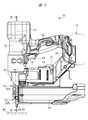
- the driving machine 10 is shown in FIGS. 1, 2 and 3.
- the driving machine 10 is a nail driving machine, and the driving machine 10 includes a housing 11, a striking unit 12, a nose unit 13, a power supply unit 14, an electric motor 15, a speed reducer 16, and a pressure accumulator container 18.
- the housing 11 has a main body portion 19, a handle 20, a motor case 21, and a mounting portion 22.
- the main body 19 has a tubular shape, and the handle 20 and the motor case 21 are connected to the main body 19.
- the mounting portion 22 is connected to the handle 20 and the motor case 21.
- the power supply unit 14 can be attached to and detached from the mounting unit 22.
- the electric motor 15 is arranged in the motor case 21.
- the pressure accumulator container 18 is provided in the main body portion 19.
- the cylinder 27 is housed in the main body 19.
- the accumulator container 18 is attached to the outer surface of the cylinder 27.
- the pressure chamber 26 is formed in the accumulator container 18 and in the cylinder 27.
- the pressure chamber 26 is filled with a compressible fluid.
- the compressible fluid for example, air or an inert gas can be used.
- the inert gas includes, for example, nitrogen gas and noble gas. In the present embodiment, it is assumed that the pressure chamber 26 is filled with air at a pressure higher than the atmospheric pressure.
- the striking portion 12 is arranged from the inside to the outside of the housing 11.
- the striking portion 12 has a piston 28 and a driver blade 29.
- the piston 28 can operate in the cylinder 27 in a direction along the center line A1.
- the center line A1 passes through the center of the cylinder.
- a seal member 120 is attached to the piston 28.
- the seal member 120 contacts the inner peripheral surface of the cylinder 27 to form a seal surface.
- the driver blade 29 is made of metal, non-ferrous metal, or steel as an example.
- the piston 28 and the driver blade 29 are provided as separate members, and the piston 28 and the driver blade 29 are connected to each other.
- the driver blade 29 has a rack.
- the rack has a plurality of protrusions arranged at intervals in the operating direction of the driver blade 29, for example, seven protrusions 61, 62, 63, 64, 65, 66, 67.
- the nose portion 13 is arranged inside and outside the main body portion 19.
- the nose portion 13 has a bumper support portion 31, an injection portion 32, and a tubular portion 33.
- the bumper 35 is arranged in the bumper support portion 31.
- the bumper 35 has a guide hole 36.
- the driver blade 29 is arranged in the guide hole 36.
- the striking portion 12 can operate in the first direction D1 and the second direction D2 along the center line A1.
- the first direction D1 and the second direction D2 are opposite to each other.
- the first direction D1 is the direction in which the piston 28 approaches the bumper 35.
- the second direction D2 is the direction in which the piston 28 is separated from the bumper 35.
- the striking portion 12 receives the pressure of the compressed air filled in the pressure chamber 26 shown in FIG. 1, and the striking portion 12 is always urged in the first direction D1.
- the operation of the striking portion 12 in the first direction D1 can be defined as descending.
- the operation of the striking portion 12 in the second direction D2 can be defined as ascending.
- the injection portion 32 is connected to the tubular portion 33 and protrudes from the bumper support portion 31 in the direction along the center line A1.
- the injection unit 32 has a blade guide 32A and a guide plate 32B.
- An injection path 37 shown in FIG. 3 is provided between the blade guide 32A and the guide plate 32B.
- the injection path 37 is a space in the direction along the center line A1.
- the driver blade 29 can operate in the injection path 37 in the direction along the center line A1.
- the blade guide 32A and the guide plate 32B guide the operation of the driver blade 29.
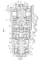
- the electric motor 15 is arranged in the motor case 21.
- the electric motor 15 is a brushless motor, and the electric motor 15 has a rotor 39 and a stator 40.
- the stator 40 is attached to the motor case 21.
- the rotor 39 is attached to the rotor shaft 41, and the first end portion of the rotor shaft 41 is rotatably supported by the motor case 21 via a bearing 42.
- the electric motor 15 is a brushless motor, and when a voltage is applied to the electric motor 15, the rotor 39 rotates about the center line A2.
- a gear case 43 is provided in the motor case 21 and in the tubular portion 33.
- the gear case 43 has a tubular shape.
- the speed reducer 16 is provided in the gear case 43.
- the speed reducer 16 includes an input element 44, an output element 45, and a plurality of sets of planetary gear mechanisms.
- the input element 44 is connected to the rotor shaft 41.
- the input element 44 is rotatably supported by a bearing 46.
- the drive member 47 is provided in the tubular portion 33.
- the drive member 47 has a wheel shaft 48 and a wheel 49 as shown in FIG.
- the wheel shaft 48 and the wheel 49 are made of metal and are integrated.
- the wheel shaft 48 is connected to the output element 45.
- the wheel shaft 48 is rotatably supported by the tubular portion 33 via bearings 50 and 51.
- the drive member 47 has a plurality of, for example, seven pins 71, 72, 73, 74, 75, 76, 77.
- the seven pins 71, 72, 73, 74, 75, 76, 77 are each made of metal.
- the seven pins 71, 72, 73, 74, 75, 76, 77 are all cylindrical.
- the seven pins 71, 72, 73, 74, 75, 76, 77 have a circular outer surface shape in a plane perpendicular to the center line A2.
- the diameter of the pin 77 is larger than the diameter of each of the pins 71, 72, 73, 74, 75, 76.
- the pins 71, 72, 73, 74, 75, 76 have the same diameter.
- the centers C1 of the pins 71, 72, 73, 74, 75, and 76 are arranged at equal intervals on the virtual circle E1.
- the virtual circle E1 is a circle centered on the center line A2.
- the center C1 of the pin 77 is arranged inside the virtual circle E1.
- the pins 71, 72, 73, 74, 75, 76, 77 are arranged in the order of rotation of the drive member 47.
- the distance between the pin 77 and the pin 71 is wider than the distance between the other pins.
- the wheel 49 has a guide hole 80, and the pin 71 is movable in the guide hole 80.
- the pin 71 moves in the guide hole 80, the position of the pin 71 in the radial direction of the drive member 47 is changed.
- the pin 71 is urged outward in the radial direction of the drive member 47 by an elastic member, for example, a metal spring.
- the rotation regulation mechanism 81 is provided in the gear case 43.
- the rotation regulation mechanism 81 enables the drive member 47 to rotate counterclockwise in FIGS. 3 and 5 by the rotational force when the electric motor 15 rotates in the forward direction.
- the rotation regulation mechanism 81 prevents the drive member 47 from rotating clockwise with a rotational force different from the rotational force of the electric motor 15.
- the trigger 82 shown in FIG. 2 is provided on the handle 20.
- the power supply unit 14 has a storage case and a plurality of battery cells housed in the storage case.
- a battery cell is a secondary battery that can be charged and discharged.
- a magazine 83 is provided, and the magazine 83 is supported by an injection portion 32 and a mounting portion 22.
- the stopper 84 is housed in the magazine 83.
- the stopper 84 is, for example, a shaft-shaped nail.
- the magazine 83 has a feeder, and the feeder sends the stopper 84 in the magazine 83 to the injection path 37.
- the control system of the driving machine 10 is configured as shown in FIG.
- the control unit 85 is provided in the mounting unit 22.
- the control unit 85 includes an input / output interface, a control circuit, an arithmetic processing unit, and a storage unit.
- the inverter circuit 86 is provided in the motor case 21.
- the inverter circuit 86 connects and disconnects the stator 40 of the electric motor 15 and the power supply unit 14.
- the inverter circuit 86 includes a plurality of switching elements, and the plurality of switching elements can be turned on and off respectively.
- a push switch 87 and a position detection sensor 88 are provided in the housing 11.
- the push switch 87 detects whether the tip of the injection unit 32 is pressed against or separated from the mating material W1 and outputs a signal.
- the position detection sensor 88 detects the position of the drive member 47 in the rotation direction and outputs a signal.
- a trigger switch 89 is provided in the handle 20. The trigger switch 89 detects whether the operating force is applied to or released from the trigger 82, and outputs a signal.
- the control unit 85 processes the signals of the push switch 87, the position detection sensor 88, and the trigger switch 89.
- the control unit 85 can process the signal of the position detection sensor 88 to estimate the position of the striking unit 12 in the direction along the center line A1. By controlling the inverter circuit 86, the control unit 85 controls the rotation and stop of the electric motor 15, the rotation speed of the electric motor 15, and the rotation direction of the electric motor 15.
- control unit 85 detects that no operating force is applied to the trigger 82 or the tip of the injection unit 32 is not pressed against the mating material W1
- the control unit 85 supplies electric power to the electric motor 15. To stop. Therefore, the electric motor 15 is stopped, and the striking portion 12 is stopped at the position shown in FIG.
- a position where the piston 28 is separated from the bumper 35 and the striking portion 12 is stopped as shown in FIG. 3 will be described as a standby position of the striking portion 12.
- the pin 77 is engaged with the protrusion 67.
- Pins 71, 72, 73, 74, 75, 76 are released from the corresponding protrusions 61, 62, 63, 64, 65, 66, 67, respectively.
- the air pressure in the pressure chamber 26 is constantly applied to the striking portion 12, and the striking portion 12 is urged in the first direction D1.
- the urging force in the first direction D1 applied to the striking portion 12 is transmitted to the drive member 47 via the protrusion 67 and the pin 77.
- the drive member 47 is urged clockwise in FIG. 3, but the rotation regulation mechanism 81 prevents the drive member 47 from rotating. According to such a principle, the striking portion 12 is stopped at the standby position shown in FIG.
- the control unit 85 detects that an operating force is applied to the trigger 82 and that the injection unit 32 is pressed against the mating material W1
- the power supply unit 14 applies a voltage to the electric motor 15 to electrically drive the motor 15.
- the motor 15 is rotated in the forward direction.
- the rotational force of the electric motor 15 is transmitted to the drive member 47 via the speed reducer 16.
- the drive member 47 rotates counterclockwise in FIG. 3, and the striking portion 12 rises.
- the striking portion 12 rises, the air pressure in the pressure chamber 26 rises.
- the position of the striking portion 12 at the time when the piston 28 is most distant from the bumper 35 is the top dead center.
- the striking portion 12 When the pin 77 is released from the protrusion 67, the striking portion 12 is lowered by the air pressure of the pressure chamber 26. In the process in which the striking portion 12 descends from the top dead center, all the pins 71, 72, 72, 74, 75, 76, 77 have protrusions 67, 66, 65, 64, 63, 62, 61 at the center line A1. It is located outside the operating range that operates in the direction along the line. When the striking portion 12 is lowered, the driver blade 29 can strike a single stopper 84 located in the injection path 37. The hit stopper 84 is driven into the mating material W1.
- the piston 28 collides with the bumper 35 after the stopper 84 is driven into the mating material W1.
- the bumper 35 absorbs a part of the kinetic energy of the striking portion 12. As shown in FIG. 9, the state in which the piston 28 is in contact with the bumper 35 is the bottom dead center of the striking portion 12.
- the tip of the injection portion 32 is separated from the mating material W1 by the reaction.
- the control unit 85 continues the rotation of the electric motor 15 even after the striking unit 12 reaches the bottom dead center and the tip of the injection unit 32 is separated from the mating material W1. Therefore, the drive member 47 is rotated counterclockwise, and the pin 71 is engaged with the protrusion 61. That is, the striking portion 12 is raised from the bottom dead center against the air pressure of the pressure chamber 26.
- the pin 72 is engaged and released from the protrusion 62, the pin 73 is engaged and released from the protrusion 63, the pin 74 is engaged and released from the protrusion 64, and the pin 75 is engaged and released from the protrusion 65.
- the pin 76 is engaged and disengaged from the protrusion 66. Then, when the control unit 85 detects that the striking unit 12 has reached the standby position as shown in FIG. 3, the control unit 85 stops the electric motor 15.
- the cross-sectional shape of the wheel 49 is U-shaped in the plane including the center line A2.
- a plurality of rims 93, 94, 95, 96, 97, 98 connecting the wheel shaft 48 and the wheel 49 are provided.
- a plurality of rims 93, 94, 95, 96, 97, 98 provided can also be defined as an arm.
- the plurality of rims 93, 94, 95, 96, 97, 98 are arranged at intervals in the rotation direction of the drive member 47.
- a space 101 is provided between the rims in the direction of rotation of the drive member 47. As shown in FIG.
- the thickness T1 of each of the plurality of rims 93, 94, 95, 96, 97, and 98 is the same in the direction along the center line A2.
- the thickness T2 of the wheel 49 in the direction along the center line A2 is larger than the thickness T1.
- the thicknesses T1 and T2 can be defined as dimensions, respectively.
- the rim 93 is connected to the wheel 49 inside the pin 72
- the rim 94 is connected to the wheel 49 inside the pin 73
- the rim 95 is connected to the wheel 49 inside the pin 74.
- the rim 96 is connected to the wheel 49 inside the pin 75
- the rim 97 is connected to the wheel 49 inside the pin 76
- the rim 98 is connected to the wheel 49 inside the pin 77.
- Each pin is independently engaged and disengaged with each protrusion.
- the position where the engagement between each pin and each protrusion is started is between the center line A2 and the tip of the injection portion 32 in the operating direction of the driver blade 29 in FIG.
- the position at which the engagement between each pin and each protrusion is started is below the center line A2 in FIG.
- the position where each pin and each protrusion are released is between the center line A2 and the bumper 35 in the operating direction of the driver blade 29 shown in FIG.
- the position at which each pin and each protrusion are released is above the center line A2 in FIG.
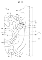
- FIG. 10 for convenience, the state immediately before the pin 77 is released from the protrusion 67 is shown.
- the load F1 received by the pin from the protrusion increases as the driver blade 29 operates in the second direction D2 from the time when the pin and the protrusion are engaged.
- the pin 77 and the protrusion 67 are engaged with each other in a state where the striking portion 12 is located at the top dead center as shown in FIG. Therefore, the load F1 received by the pin 77 shown in FIG. 10 is higher than the load F1 received by the pin when the other pin engages with the protrusion.
- the load F1 received immediately before the pin 77 is released from the protrusion 67 is the highest value.
- the load received by the pin 73 is transmitted to the rim 94, the load received by the pin 74 is transmitted to the rim 95, the load received by the pin 75 is transmitted to the rim 96, the load received by the pin 76 is transmitted to the rim 97, and the load received by the pin 76 is transmitted to the rim 97.
- the load received by is transmitted to the rim 98.
- the rim 98 has edges 98A, 98B and the rim 97 has edges 97A, 97B.
- the rim 96 has edges 96A and 96B, and the rim 95 has edges 95A and 95B.
- the edge 98A is located behind the edge 98B in the rotational direction of the drive member 47.
- the edge portion 97A is located behind the edge portion 97B in the rotation direction of the drive member 47.
- the edge 96A is located behind the edge 96B in the rotational direction of the drive member 47.
- the edge portion 95A is located behind the edge portion 95B in the rotation direction of the drive member 47.
- the radius of the virtual circle E1 and the diameter of each pin are set in FIG. 10 based on the load F1 that each pin receives from each protrusion of the driver blade 29.
- the load F1 is determined based on the distance between each protrusion and the center line A2 and the air pressure in the pressure chamber 26.
- the distance between each protrusion and the center line A2 is the distance in the direction along the virtual line B1.
- the virtual line B1 is a straight line that intersects the center line A1 at 90 degrees.
- the center line G1 in the width direction of the rim 98 passes through the center C1 of the rim 98.
- the center line G2 in the width direction of the rim 97 passes through the center C1 of the rim 97.
- the widthwise center line G3 of the rim 96 passes through the center C1 of the rim 96.
- the widthwise center line G4 of the rim 95 passes through the center C1 of the rim 95.
- the width L1 of the rim 98, the width L2 of the rim 97, the width L3 of the rim 96, and the width L4 of the rim 95 are determined based on the load F1 that each pin receives from each protrusion.
- each tangent line H1 is in contact with the outer peripheral surface 48A of the wheel shaft 48.
- the outer peripheral surface 48A is a portion of the wheel shaft 48 to which each rim is connected.
- the width of each rim is the width of each rim in a direction perpendicular to the centerline of each rim.
- the width L1 is set to be larger than the width L2, the width L2 is set to be larger than the width L3, and the width L3 is set to be larger than the width L4. That is, the strength of the rim 98 is higher than the strength of the rim 97, the strength of the rim 97 is higher than the strength of the rim 96, and the strength of the rim 96 is higher than the strength of the rim 95.
- the load F1 is maximized when the pin 77 and the protrusion 67 are engaged with each other.
- the strength of the rim 98 to be high, the weight of the wheel 49 is reduced and the durability of the wheel 49 is improved.
- the tangent line of each rim is set at a position where it contacts the outer peripheral surface 48A. Therefore, just before each pin is released from each protrusion, as shown in FIG. 10, an acute angle formed between the straight line B2 at which each pin passes through the contact point P1 with each protrusion and the tangent line of each rim.
- the side angle ⁇ 1 can be 45 degrees or more. In a plane perpendicular to the center line A2, the straight line B2 is parallel to the virtual line B1. Therefore, it is possible to suppress the deformation of each rim.
- the drive member 47 is provided with a lubrication mechanism that lubricates a portion where each pin and each protrusion are engaged and disengaged.
- the lubrication mechanism 90 shown in FIG. 5 has a holding hole 91 and a supply path 92.
- the holding hole 91 is provided in the wheel shaft 48.
- the holding hole 91 is provided around the center line A2. That is, the wheel shaft 48 is a cylinder having a holding hole 91.
- the supply path 92 is connected to the holding hole 91 and is provided over the rim 98 and the wheel 49. In the radial direction of the drive member 47, the outermost open end 92A of the supply path 92 is located between the wheel shaft 48 and the pin 77. Further, a lubricant, for example, grease is contained in the holding hole 91.
- Grease is a gel-like body in which a liquid lubricating oil is retained by a thickener. The viscosity of grease is higher than the viscosity of lubricating oil alone.
- the tubular portion 33 has a hole 33A. The user can remove the plug 100 and supply grease from the hole 33A to the holding hole 91.
- the driving machine 10 of the present embodiment is provided with a holding hole 91 for accommodating grease in the wheel shaft 48. That is, the wheel shaft 48 is hollow. Therefore, it is not necessary to provide a dedicated component other than the drive member 47 as the lubrication mechanism 90. Therefore, it is possible to suppress an increase in the number of parts of the driving machine 10, and it is possible to suppress an increase in the weight of the driving machine 10. In other words, it is possible to reduce the weight of the driving machine 10. Further, a space 101 is provided between the rims. Therefore, the weight of the driving machine 10 can be further reduced.
- FIG. 11 is a front sectional view showing another example of the driving machine 10.
- the drive member 47 has a pin 102 and a gear 103 as shown in FIG.
- the pin 102 is movable within the guide hole 104.
- the gear 103 has teeth 105, 106, 107, 108, 109, 110.
- the pins 102 and the teeth 105, 106, 107, 108, 109, 110 are arranged at intervals in the rotation direction of the drive member 47.
- the pin 102 can engage and disengage the protrusion 61, the tooth 105 can engage and disengage the protrusion 62, and the tooth 106 engages and disengages the protrusion 63.
- Tooth 107 can be engaged and disengaged with protrusion 64, tooth 108 can be engaged and disengaged with protrusion 65, and tooth 109 can be engaged and disengaged with protrusion 66.
- the teeth 110 can engage and disengage the protrusions 67. Therefore, when the pin 102 or any of the teeth is engaged with any of the protrusions, the striking portion 12 rises. When all the pins 102 and the teeth are released from the protrusions, the striking portion 12 is lowered.
- the tangents H2 passing through the edges of the teeth 107, 108, 109, 110 all come into contact with the outer peripheral surface 48A of the wheel shaft 48.
- the width L5 of the tooth 110 is larger than the width L6 of the tooth 109
- the width L6 of the tooth 109 is larger than the width L7 of the tooth 108
- the width L6 of the tooth 108 is larger than the width L8 of the tooth 107.
- the wheel shaft 48 has a holding hole 91, and the supply path 111 is connected to the holding hole 91.
- the supply path 111 is provided in the tooth 110 and is opened on the surface of the tooth 110.
- the grease lubricating oil contained in the holding hole 91 passes through the supply path 111 and is supplied to the contact portion between the tooth and the protrusion and the contact portion between the pin 102 and the protrusion 61. Therefore, the pin 102 and each protrusion can be lubricated.
- the driving machine 10 is an example of a driving machine.
- the first direction D1 in which the striking portion 12 descends is an example of the first direction.
- the second direction D2 in which the striking portion 12 rises is an example of the second direction.
- the striking portion 12 is an example of the striking portion.
- the pressure accumulator container 18 is an example of the first urging unit.
- the drive member 47 is an example of the drive member.
- the wheel shaft 48 is an example of a rotating shaft.
- the wheel 49 is an example of a disk member.
- the electric motor 15, the drive member 47, the pins 71 to 77, and the protrusions 61 to 67 are examples of the second urging portion, respectively.
- the electric motor 15 is an example of an electric motor.
- Pins 71 to 77 are examples of the first engaging portion, respectively.
- the protrusions 61 to 67 are examples of the second engaging portion, respectively.
- the pin 102 and the teeth 105 to 110 are examples of the first engaging portion and the second urging portion, respectively.
- Pins 71 and 102 are examples of first engaging portions, respectively.
- the holding hole 91 is an example of a holding portion.
- the supply paths 92 and 111 are examples of supply paths.
- the rims 93 to 98 are examples of connecting portions and arms.
- the rim 98 is an example of the final arm.
- the rims 95 to 97 are examples of normal arms.
- Space 101 is an example of space.
- the pin 77 is an example of the last engaging portion.
- the diameter of the pin 77 is an example of the thickness of the last engaging portion.
- Pins 71 to 76 are examples of wheel engaging portions and are usually examples of engaging portions.
- the respective diameters of the pins 71 to 76 are examples of the thickness of the normal engaging portion.
- the tooth 110 is an example of the last engaging portion.
- the teeth 105 to 109 are examples of normal engaging portions, respectively.
- the width L5 is an example of the thickness of the last engaging portion.
- the width L6 to the width L8 are examples of the thickness of the normal engaging portion, respectively.
- the center line A2 is an example of a rotation center line.
- FIG. 6B is an example of a plane perpendicular to the rotation center line of the rotating member.
- the outer peripheral surface 48A of the wheel shaft 48 is an example of the outer surface of the rotating member.
- the tangents H1 and H2 are examples of tangents, respectively.
- the first urging part is a pressure accumulator that operates the striking part by the pressure of the compressible fluid, one that operates the striking part by the elastic force of the solid spring, and the striking part by the repulsive force or the attractive force of the magnet. Including what makes you.
- the supply path may be as long as the lubricant can pass through it, and the supply path includes passages, gaps, holes, and grooves.
- the first engaging portion and the second engaging portion may be engaged and disengaged from each other, and the first engaging portion and the second engaging portion may be any of a pin, a tooth, and a protrusion, respectively.
- the lubricant may be a single lubricating oil instead of the grease.
- the power supply unit that supplies electric power to the electric motor may be either a DC power supply or an AC power supply.
- the fasteners include axially shaped nails, arched tackers, studs and the like.
Landscapes
- Engineering & Computer Science (AREA)
- Mechanical Engineering (AREA)
- Physics & Mathematics (AREA)
- Fluid Mechanics (AREA)
- Portable Nailing Machines And Staplers (AREA)
Abstract
ピンを潤滑可能であり、かつ、重量の増加を抑制可能な打込機を提供する。第1方向及び第2方向に作動可能な打撃部と、打撃部に付勢力を付加して第1方向に作動させる第1付勢部と、打撃部を第2方向に作動させる第2付勢部と、を有し、第2付勢部は、モータと、モータによって回転される駆動部材47と、駆動部材47に設けられたピン77と、打撃部に設けられ、かつ、ピン77が係合及び解放される突起と、を有する、打込機であって、駆動部材47は、ホイール軸48と、駆動部材47の径方向でホイール軸48の外側に設けられ、かつ、ピン77を備えたホイール49と、潤滑剤を保持する保持孔91と、潤滑剤を保持部孔91からピン77に供給する供給路92と、を有する。
Description
本発明は、止具を打撃可能な打撃部と、打撃部を作動させる付勢部と、を備えた打込機に関する。
止具を打撃可能な打撃部と、打撃部を作動させる付勢部と、を備えた打込機の一例が、特許文献1に記載されている。特許文献1に記載された打込機は、止具を打撃可能な打撃部としてのドライバブレードと、ドライバブレードに固定されたピストンと、ピストンが作動可能に収容されたシリンダと、シリンダが内部に設けられたハウジングと、を有する。
また、ハウジング内に蓄圧室が設けられ、圧縮空気が蓄圧室に充填されている。さらに、ハウジングは、モータケース及びハンドルを有する。電動モータがモータケース内に設けられ、電動モータによって回転されるホイールが設けられている。さらに、第1係合部部としてのピンが、ホイールの回転方向に沿って複数設けられている。ドライバブレードは、第2係合部としてのラックを有する。
さらに、トリガがハンドルに設けられ、ノーズ部がハウジングに取り付けられている。ノーズ部は、射出通路を有する。プッシュスイッチがノーズ部に取り付けられている。また、コントローラがハウジング内に設けられている。さらに、マガジンがハウジングに取り付けられており、マガジンは止具を収容している。マガジンは供給機構を備え、マガジンに収容されている止具は、供給機構によって1本づつ射出通路へ供給される。
特許文献1に記載された打込機は、プッシュスイッチが被打込材に押し付けられ、かつトリガに操作力が付加されると、コントローラが電動モータを回転させる。ホイールは、電動モータによって回転され、ピンとラックとが係合すると、ドライバブレードが押し上げられ、かつ、ピストンが上昇する。ピストンが上昇すると、蓄圧室の空気圧が上昇する。そして、ピンがラックから解放されると、ピストン及びドライバブレードが空気圧で下降し、ドライバブレードは、射出通路の止具を被打込材へ打ち込む。
特許文献1に記載された打込機は、潤滑油供給機構を有する。潤滑油供給機構は、ホイールと一体回転するように設けられたフェルトを備えている。フェルトは、潤滑油を含浸しており、ピンの外周面がフェルトに接触されている。このため、フェルトが含浸している潤滑油がピンの表面に供給されるとともに、ピンを介してラックにも供給される。したがって、ピン及びラックの双方が潤滑される。
本願発明者は、第1係合部及び第2係合部を潤滑する潤滑機構を専用で設けると、打込機の重量が増加するという課題を認識した。
本発明の目的は、第1係合部及び第2係合部を潤滑可能であり、かつ、重量の増加を抑制可能な打込機を提供することである。
一実施形態の打込機は、止具を打撃可能な第1方向、及び前記第1方向とは逆の第2方向に作動可能な打撃部と、前記打撃部に付勢力を付加して前記第1方向に作動させる第1付勢部と、前記打撃部に付勢力を付加することにより、前記打撃部を前記第1付勢部の付勢力に抗して前記第2方向に作動させる第2付勢部と、を有し、前記第2付勢部は、モータと、前記モータによって回転される駆動部材と、前記駆動部材に設けられた第1係合部と、前記打撃部に設けられ、かつ、前記第1係合部が係合及び解放される第2係合部と、を有する、打込機であって、前記駆動部材は、前記回転軸と、前記駆動部材の径方向で前記回転軸の外側に設けられ、かつ、前記第1係合部を備えた円板部材と、潤滑剤を保持する保持部と、前記潤滑剤を前記保持部から前記第1係合部に供給する供給路と、を有する。
一実施形態の打込機は、駆動部材が保持部及び供給路を有しており、潤滑機構を専用に設けずに済む。したがって、部品点数の増加を抑制でき、打込機の重量が増加することを抑制できる。
本発明の打込機の一実施形態を図面を参照して説明する。
図1、図2及び図3には、打込機10が示されている。打込機10は釘打機であり、打込機10は、ハウジング11、打撃部12、ノーズ部13、電源部14、電動モータ15、減速機16及び蓄圧容器18を有する。ハウジング11は、本体部19、ハンドル20、モータケース21及び装着部22を有する。本体部19は筒形状であり、ハンドル20及びモータケース21は、本体部19に接続されている。装着部22は、ハンドル20及びモータケース21に接続されている。
電源部14は、装着部22に取り付け及び取り外しが可能である。電動モータ15は、モータケース21内に配置されている。蓄圧容器18は、本体部19内に設けられている。シリンダ27が本体部19内に収容されている。蓄圧容器18は、シリンダ27の外面に取り付けられている。圧力室26が、蓄圧容器18内及びシリンダ27内に亘って形成されている。圧力室26に圧縮性流体が充填されている。圧縮性流体としては、例えば、空気、不活性ガスを用いることができる。不活性ガスは、一例として、窒素ガス、希ガスを含む。本実施形態では、空気が、圧力室26に大気圧よりも高圧の状態で充填されているものとする。
打撃部12は、ハウジング11の内部から外部に亘って配置されている。打撃部12は、ピストン28及びドライバブレード29を有する。ピストン28は、シリンダ27内で中心線A1に沿った方向に作動可能である。中心線A1は、シリンダの中心を通る。ピストン28にシール部材120が取り付けられている。シール部材120は、シリンダ27の内周面に接触してシール面を形成する。ドライバブレード29は、一例として金属製、非鉄金属製、鋼製である。図3に示す打撃部12は、ピストン28とドライバブレード29とが別部材で設けられ、ピストン28とドライバブレード29とが連結されている。ドライバブレード29は、ラックを有する。ラックは、ドライバブレード29の作動方向に間隔をおいて配置された複数個の突起、一例として7個の突起61,62,63,64,65,66,67を有する。
ノーズ部13は、本体部19の内外に亘って配置されている。ノーズ部13は、バンパ支持部31、射出部32及び筒部33を有する。バンパ支持部31内にバンパ35が配置されている。バンパ35はガイド孔36を有する。ドライバブレード29は、ガイド孔36内に配置されている。
打撃部12は、中心線A1に沿った第1方向D1及び第2方向D2で作動可能である。第1方向D1と第2方向D2とは、互いに逆方向である。第1方向D1は、ピストン28がバンパ35に接近する方向である。第2方向D2は、ピストン28がバンパ35から離間する方向である。打撃部12は、図1に示す圧力室26に充填された圧縮空気の圧力を受けており、打撃部12は、第1方向D1で常に付勢されている。打撃部12が第1方向D1で作動することを、下降と定義可能である。打撃部12が第2方向D2で作動することを、上昇と定義可能である。
射出部32は筒部33に接続され、かつ、バンパ支持部31から中心線A1に沿った方向に突出されている。射出部32は、ブレードガイド32A及びガイドプレート32Bを有する。ブレードガイド32Aとガイドプレート32Bとの間に、図3に示す射出路37が設けられている。射出路37は、中心線A1に沿った方向の空間である。ドライバブレード29は、射出路37内で中心線A1に沿った方向に作動可能である。ブレードガイド32A及びガイドプレート32Bは、ドライバブレード29の作動をガイドする。
図4のように、モータケース21内に電動モータ15が配置されている。電動モータ15は、ブラシレスモータであり、電動モータ15は、ロータ39及びステータ40を有する。ステータ40は、モータケース21に取り付けられている。ロータ39はロータ軸41に取り付けられ、ロータ軸41の第1端部は、軸受42を介してモータケース21により回転可能に支持されている。電動モータ15は、ブラシレスモータであり、電動モータ15に電圧が印加されると、ロータ39は、中心線A2を中心として回転する。
モータケース21内及び筒部33内に亘ってギヤケース43が設けられている。ギヤケース43は筒形状である。減速機16はギヤケース43内に設けられている。減速機16は、入力要素44、出力要素45及び複数組のプラネタリギヤ機構を備えている。入力要素44は、ロータ軸41に連結されている。入力要素44は、軸受46により回転可能に支持されている。電動モータ15の回転力が減速機16の入力要素44に伝達されると、出力要素45の回転速度は、入力要素の回転速度に対して低速となる。
駆動部材47が、筒部33内に設けられている。駆動部材47は、図5のように、ホイール軸48及びホイール49を有する。ホイール軸48、ホイール49は、金属製であり、かつ、一体である。ホイール軸48は、出力要素45に連結されている。電動モータ15の回転力が減速機16を経由してホイール軸48に伝達されると、駆動部材47は、図3で反時計方向に回転可能である。
ホイール軸48は、軸受50,51を介して筒部33によって回転可能に支持されている。また、図3、図6A及び図6Bのように、駆動部材47は、複数個、一例として、7個のピン71,72,73,74,75,76,77を有する。7個のピン71,72,73,74,75,76,77は、それぞれ金属製である。7個のピン71,72,73,74,75,76,77は、何れも円柱形状である。7個のピン71,72,73,74,75,76,77は、中心線A2に対して垂直な平面内における外面形状が円形である。また、ピン77の直径は、ピン71,72,73,74,75,76のそれぞれの直径よりも大きい。ピン71,72,73,74,75,76の直径は同一である。ピン71,72,73,74,75,76のそれぞれの中心C1は、仮想円E1上に等間隔で配置されている。仮想円E1は、中心線A2を中心とする円である。ピン77の中心C1は、仮想円E1よりも内側に配置されている。
本実施形態では、駆動部材47が反時計方向D3で回転する場合、駆動部材47の回転方向でピン71,72,73,74,75,76,77の順序で配置されている。駆動部材47の回転方向で、ピン77とピン71との間の間隔は、他のピン同士の間隔よりも広い。
ホイール49はガイド孔80を有し、ピン71は、ガイド孔80内で移動可能である。ピン71がガイド孔80内で移動すると、駆動部材47の径方向におけるピン71の位置が変更される。なお、ピン71は、弾性部材、例えば金属製のスプリングにより、駆動部材47の径方向で外側に向けて付勢されている。
図4のように、回転規制機構81がギヤケース43内に設けられている。回転規制機構81は、電動モータ15が正回転した際の回転力で、駆動部材47が図3及び図5で反時計回りに回転することを可能とする。回転規制機構81は、電動モータ15の回転力とは異なる回転力で、駆動部材47が時計回りに回転することを阻止する。
図2に示すトリガ82がハンドル20に設けられている。電源部14は、収容ケースと、収容ケース内に収容した複数の電池セルとを有する。電池セルは、充電及び放電が可能な二次電池である。さらに、マガジン83が設けられ、マガジン83は、射出部32及び装着部22により支持されている。マガジン83内に止具84が収容される。止具84は、一例として軸形状の釘である。マガジン83はフィーダを有し、フィーダは、マガジン83内の止具84を射出路37へ送る。
打込機10の制御系統は、図7のように構成されている。制御部85が装着部22内に設けられている。制御部85は、入出力インタフェース、制御回路、演算処理部及び記憶部を有する。また、インバータ回路86がモータケース21内に設けられている。インバータ回路86は、電動モータ15のステータ40と電源部14とを接続及び遮断する。インバータ回路86は、複数のスイッチング素子を備え、複数のスイッチング素子はそれぞれオン・オフが可能である。
また、プッシュスイッチ87、位置検出センサ88がハウジング11に設けられている。プッシュスイッチ87は、射出部32の先端が相手材W1に押し付けられているか離間されているかを検出して信号を出力する。位置検出センサ88は、駆動部材47の回転方向における位置を検出して信号を出力する。さらに、トリガスイッチ89が、ハンドル20内に設けられている。トリガスイッチ89は、トリガ82に操作力が付加されているか解除されているかを検出して信号を出力する。制御部85は、プッシュスイッチ87、位置検出センサ88、トリガスイッチ89の信号を処理する。制御部85は、位置検出センサ88の信号を処理して、中心線A1に沿った方向における打撃部12の位置を推定可能である。制御部85は、インバータ回路86を制御することにより、電動モータ15の回転及び停止、電動モータ15の回転速度、電動モータ15の回転方向を制御する。
次に、打込機10の使用例を説明する。制御部85は、トリガ82に操作力が加えられていないこと、または射出部32の先端が相手材W1に押し付けられていないこと、のうち、少なくとも一方を検出すると、電動モータ15に対する電力の供給を停止する。このため、電動モータ15は停止し、打撃部12は、図3に示す位置で停止されている。
ここでは、図3のようにピストン28がバンパ35から離間して打撃部12が停止されている位置を、打撃部12の待機位置として説明する。ピン77が突起67に係合されている。ピン71,72,73,74,75,76は、対応する突起61,62,63,64,65,66,67からそれぞれ解放されている。圧力室26の空気圧は、常に打撃部12に加わっており、打撃部12は第1方向D1で付勢されている。打撃部12に加わる第1方向D1の付勢力は、突起67及びピン77を経由して駆動部材47に伝達されている。駆動部材47は、図3で時計回りに付勢されているが、回転規制機構81は、駆動部材47の回転を阻止している。このような原理により、打撃部12は、図3に示す待機位置で停止されている。
制御部85は、トリガ82に操作力が付加されていること、及び射出部32が相手材W1に押し付けられていること、を検出すると、電源部14から電動モータ15に電圧を印加させ、電動モータ15を正回転させる。電動モータ15の回転力は、減速機16を経由して駆動部材47に伝達される。すると、駆動部材47は、図3で反時計回りに回転し、打撃部12が上昇する。打撃部12が上昇すると、圧力室26の空気圧が上昇する。図8のように、ピストン28がバンパ35から最も離間した時点における打撃部12の位置が上死点である。
ピン77が突起67から解放されると、打撃部12は、圧力室26の空気圧で下降する。打撃部12が上死点から下降する行程において、全てのピン71,72,72,74,75,76,77は、突起67,66,65,64,63,62,61が中心線A1に沿った方向に作動する作動範囲外に位置する。打撃部12が下降すると、ドライバブレード29は、射出路37に位置する1本の止具84を打撃可能である。打撃された止具84は相手材W1に打ち込まれる。
ピストン28は、止具84が相手材W1に打ち込まれた後、バンパ35に衝突する。バンパ35は、打撃部12の運動エネルギの一部を吸収する。図9のように、ピストン28がバンパ35に接触した状態が、打撃部12の下死点である。打撃部12が止具84を相手材W1に打ち込むと、その反動で射出部32の先端は、相手材W1から離間される。
制御部85は、打撃部12が下死点に到達し、かつ、射出部32の先端が相手材W1から離間された後も、電動モータ15の回転を継続させる。このため、駆動部材47は反時計回りに回転され、ピン71が突起61に係合される。つまり、打撃部12は、圧力室26の空気圧に抗して下死点から上昇される。
打撃部12が上昇する過程で、ピン72は突起62に係合及び解放され、ピン73は突起63に係合及び解放され、ピン74は突起64に係合及び解放され、ピン75は突起65に係合及び解放され、ピン76は突起66に係合及び解放される。そして、制御部85は、打撃部12が図3のように待機位置に到達したことを検出すると、電動モータ15を停止させる。
さらに、駆動部材47の構成を具体的に説明する。図5のように、中心線A2を含む平面内において、ホイール49の断面形状は、U字形である。そして、ホイール軸48とホイール49とを接続する複数のリム93,94,95,96,97,98が設けられている。複数のリム93,94,95,96,97,98が設けられているは、それぞれアームと定義することも可能である。図6Aのように、複数のリム93,94,95,96,97,98は、駆動部材47の回転方向に間隔をおいて配置されている。駆動部材47の回転方向で、各リム同士の間に空間101が設けられている。図5のように、中心線A2に沿った方向において、複数のリム93,94,95,96,97,98のそれぞれの厚さT1は同一である。中心線A2に沿った方向におけるホイール49の厚さT2は、厚さT1よりも大きい。厚さT1,T2は、それぞれ寸法として定義可能である。
駆動部材47の径方向において、リム93は、ピン72の内側でホイール49に接続され、リム94は、ピン73の内側でホイール49に接続され、リム95は、ピン74の内側でホイール49に配置され、リム96は、ピン75の内側でホイール49に接続され、リム97は、ピン76の内側でホイール49に接続され、リム98は、ピン77の内側でホイール49に接続されている。
各ピンは、各突起にそれぞれ単独で係合及び解放される。各ピンと各突起との係合が開始される位置は、図3におけるドライバブレード29の作動方向において、中心線A2と射出部32の先端との間である。各ピンと各突起との係合が開始される位置は、図10において、中心線A2よりも下方である。各ピンと各突起とが解放される位置は、図8に示すドライバブレード29の作動方向において、中心線A2とバンパ35との間ある。各ピンと各突起とが解放される位置は、図10において中心線A2よりも上方である。
図10では、便宜上、ピン77が突起67から解放される直前の状態が示されている。ピンが突起から受ける荷重F1は、ピンと突起とが係合された時点から、ドライバブレード29が第2方向D2で作動することに伴い上昇する。また、打撃部12が図8のように上死点に位置する状態において、ピン77と突起67とが係合されている。このため、図10に示されたピン77が受ける荷重F1は、他のピンが突起と係合し、かつ、そのピンが受ける荷重F1よりも高い。特に、ピン77が突起67から解放される直前に受ける荷重F1は最高値である。
ピン73が受ける荷重はリム94に伝達され、ピン74が受ける荷重はリム95に伝達され、ピン75が受ける荷重はリム96に伝達され、ピン76が受ける荷重はリム97に伝達され、ピン76が受ける荷重はリム98に伝達される。
中心線A2に対して垂直な平面を表す図6Bにおいて、リム98は、縁部98A,98Bを有し、リム97は、縁部97A,97Bを有する。またリム96は、縁部96A,96Bを有し、リム95は、縁部95A,95Bを有する。駆動部材47の回転方向で縁部98Aは縁部98Bよりも後方に位置する。駆動部材47の回転方向で縁部97Aは縁部97Bよりも後方に位置する。駆動部材47の回転方向で縁部96Aは縁部96Bよりも後方に位置する。駆動部材47の回転方向で縁部95Aは縁部95Bよりも後方に位置する。
仮想円E1の半径及び各ピンの直径は、図10において、各ピンがドライバブレード29の各突起から受ける荷重F1に基づいて設定される。荷重F1は、各突起と中心線A2との距離、圧力室26の空気圧に基づいて定まる。各突起と中心線A2との距離は、仮想線B1に沿った方向の距離である。中心線A2に対して垂直な平面を表す図10において、仮想線B1は、中心線A1に対して90度で交差する直線である。
また、リム98の幅方向の中心線G1は、リム98の中心C1を通る。リム97の幅方向の中心線G2は、リム97の中心C1を通る。リム96の幅方向の中心線G3は、リム96の中心C1を通る。リム95の幅方向の中心線G4は、リム95の中心C1を通る。リム98の幅L1、リム97の幅L2、リム96の幅L3、リム95の幅L4は、各ピンが各突起から受ける荷重F1に基づいて定まる。そして、縁部98A,97A,96A,95は、それぞれの接線H1上に配置されている。中心線A2に対して垂直な平面視である図6Bにおいて、ホイール軸48の外周面48Aは円形である。各接線H1は、ホイール軸48の外周面48Aに接する。外周面48Aは、ホイール軸48のうち、各リムが接続されている箇所である。各リムの幅は、各リムの中心線に対して直角な方向における各リムの幅である。
さらに、幅L1は幅L2よりも大きく、幅L2は幅L3よりも大きく、幅L3は幅L4よりも大きく設定されている。つまり、リム98の強度はリム97の強度よりも高く、リム97の強度はリム96の強度よりも高く、リム96の強度はリム95の強度よりも高い。ピン77と突起67とが係合した状態で荷重F1が最大になる。これに対して、リム98の強度を高く設定することで、ホイール49の軽量化を図り、かつ、ホイール49の耐久性を向上させている。
ところで、各ピンが各突起から解放される直前で、各ピンが受ける荷重が最高になる。本実施形態では、各リムの接線が外周面48Aに接触する位置に設定されている。このため、各ピンが各突起から解放される直前において、図10に示すように、各ピンが各突起との接触点P1を通る直線B2と、各リムの接線との間に形成される鋭角側の角度θ1を45度以上にすることができる。中心線A2に対して垂直な平面内で、直線B2は、仮想線B1と平行である。したがって、各リムが変形することを抑制可能である。
さらに、駆動部材47が回転されると、各ピンと各突起とが係合及び解放される。このため、各ピンと各突起とが係合及び解放される箇所を潤滑する潤滑機構が、駆動部材47に設けられている。図5に示す潤滑機構90は、保持孔91及び供給路92を有する。保持孔91は、ホイール軸48に設けられている。保持孔91は、中心線A2を中心として設けられている。つまり、ホイール軸48は、保持孔91を有する筒体である。
供給路92は、保持孔91につながり、かつ、リム98及びホイール49に亘って設けられている。駆動部材47の径方向で、供給路92の最も外側の開口端92Aは、ホイール軸48と、ピン77との間に位置する。さらに、保持孔91に潤滑剤、例えば、グリースが収容されている。グリースは、液体の潤滑油を増ちょう剤によって保持したジェル状体である。グリースの粘度は、潤滑油単体の粘度よりも高い。
ピンと突起との係合及び摺動による摩擦熱でホイール軸48の温度が上昇すると、グリースが溶解し、潤滑油が保持孔91から供給路92を通ってホイール49の表面へ供給される。駆動部材47が回転すると、遠心力で潤滑油がホイール49の表面へ供給される。たがって、各ピン及び各突起を潤滑でき、各ピン及び各突起が、摩耗または変形することを抑制できる。保持孔91の中心線A2に沿った方向における端部は、プラグ100によってそれぞれ塞がれている。このため、グリースが、保持孔91の中心線A2方向の端部から漏れることを防止できる。図4のように、筒部33は孔33Aを有している。ユーザは、プラグ100を取り外し、かつ、孔33Aから保持孔91へグリースを供給可能である。
本実施形態の打込機10は、ホイール軸48にグリースを収容する保持孔91が設けられている。すなわち、ホイール軸48は中空である。このため、潤滑機構90として駆動部材47の他に専用の部品を設けずに済む。したがって、打込機10の部品点数が増加することを抑制でき、かつ、打込機10の重量が増加することを抑制できる。言い換えれば、打込機10を軽量化することが可能である。また、各リム同士の間に空間101が設けられている。したがって、打込機10の軽量化を更に図ることができる。
図11は、打込機10の他の例を示す正面断面図である。駆動部材47は、図12のように、ピン102及びギヤ103を有する。ピン102は、ガイド孔104内で移動可能である。ギヤ103は、歯105,106,107,108,109,110を有する。ピン102及び歯105,106,107,108,109,110は、駆動部材47の回転方向に間隔をおいて配置されている。
駆動部材47が反時計回りD3で回転すると、ピン102は、突起61に係合及び解放可能であり、歯105は、突起62に係合及び解放可能であり、歯106は、突起63に係合及び解放可能であり、歯107は、突起64に係合及び解放可能であり、歯108は、突起65に係合及び解放可能であり、歯109は、突起66に係合及び解放可能であり、歯110は、突起67に係合及び解放可能である。このため、ピン102または何れかの歯が何れかの突起に係合されていると、打撃部12は上昇する。ピン102及び歯が全て突起から解放されると、打撃部12は下降する。
歯107,108,109,110の縁部を通る接線H2は、全てホイール軸48の外周面48Aに接触する。歯110の幅L5は、歯109の幅L6よりも大きく、歯109の幅L6は、歯108の幅L7よりも大きく、歯108の幅L6は、歯107の幅L8よりも大きい。ホイール軸48は保持孔91を有し、保持孔91に供給路111が接続されている。供給路111は、歯110に設けられ、歯110の表面で開口されている。保持孔91内に収容されたグリースの潤滑油は、供給路111を通り、歯と突起との接触部、ピン102と突起61との接触部に供給される。したがって、ピン102及び各突起を潤滑可能である。
本実施形態において開示された事項の技術的意味の一例は、次の通りである。打込機10は、打込機の一例である。打撃部12が下降する第1方向D1は、第1方向の一例である。打撃部12が上昇する第2方向D2は、第2方向の一例である。打撃部12は、打撃部の一例である。蓄圧容器18は、第1付勢部の一例である。駆動部材47は、駆動部材の一例である。ホイール軸48は、回転軸の一例である。ホイール49は、円板部材の一例である。電動モータ15、駆動部材47、ピン71~ピン77、突起61~突起67は、それぞれ第2付勢部の一例である。電動モータ15は、電動モータの一例である。ピン71~ピン77は、それぞれ第1係合部の一例である。突起61~突起67は、それぞれ第2係合部の一例である。また、ピン102、歯105~歯110は、それぞれ第1係合部及び第2付勢部の一例である。ピン71,102は、それぞれ最初係合部の一例である。保持孔91は、保持部の一例である。供給路92,111は、供給路の一例である。リム93~リム98は、接続部及びアームの一例である。リム98は、最終アームの一例である。リム95~リム97は、通常アームの一例である。幅L1は、最終アームの厚さの一例であり、幅L2~幅L4は、通常アームの厚さの一例である。空間101は、空間の一例である。
ピン77は、最後係合部の一例である。ピン77の直径は、最後係合部の厚さの一例である。ピン71~ピン76は、それぞれホイール係合部の一例であり、かつ、通常係合部の一例である。ピン71~ピン76のそれぞれの直径は、それぞれ通常係合部の厚さの一例である。歯110は、最後係合部の一例である。歯105~歯109は、それぞれ通常係合部の一例である。幅L5は、最後係合部の厚さの一例である。幅L6~幅L8は、それぞれ通常係合部の厚さの一例である。中心線A2は、回転中心線の一例である。図6Bは、回転部材の回転中心線に対して垂直な平面の一例である。ホイール軸48の外周面48Aは、回転部材の外面の一例である。接線H1,H2は、それぞれ接線の一例である。
打込機は、上記実施形態に限定されるものではなく、その要旨を逸脱しない範囲で種々変更可能である。例えば、第1付勢部は、圧縮性流体の圧力で打撃部を作動させる蓄圧容器の他、固体スプリングの弾性力で打撃部を作動させるもの、磁石の反発力または吸引力で打撃部を作動させるもの、を含む。供給路は、潤滑剤が通過可能であればよく、供給路は、通路、隙間、孔、溝を含む。第1係合部及び第2係合部は、互いに係合及び解放が可能であればよく、第1係合部及び第2係合部は、それぞれピン、歯、突起の何れでもよい。また、潤滑剤は、グリースに代えて潤滑油単体であってもよい。電動モータに電力を供給する電源部は、直流電源または交流電源の何れでもよい。さらに、止具は、軸形状の釘、アーチ形状のタッカ、鋲等を含む。
10…打込機、12…打撃部、15…電動モータ、18…蓄圧容器、47…駆動部材、48…ホイール軸、48A…外周面、49…ホイール、61~67…突起、71~77,102…ピン、92,111…供給路、93~98…リム、101…空間、105~110…歯、A2…中心線、D1…第1方向、D2…第2方向、H1,H2…接線、L1~L8…幅
Claims (9)
- 止具を打撃可能な第1方向、及び前記第1方向とは逆の第2方向に作動可能な打撃部と、
前記打撃部に付勢力を付加して前記第1方向に作動させる第1付勢部と、
前記打撃部に付勢力を付加することにより、前記打撃部を前記第1付勢部の付勢力に抗して前記第2方向に作動させる第2付勢部と、
を有し、
前記第2付勢部は、
モータと、
前記モータによって回転される駆動部材と、
前記駆動部材に設けられた第1係合部と、
前記打撃部に設けられ、かつ、前記第1係合部が係合及び解放される第2係合部と、
を有する、打込機であって、
前記駆動部材は、
回転軸と、
前記駆動部材の径方向で前記回転軸の外側に設けられた前記第1係合部と、
潤滑剤を保持する保持部と、
前記潤滑剤を前記保持部から前記第1係合部に供給する供給路と、
を有する、打込機。 - 前記保持部は、前記回転軸に設けられた孔である、請求項1記載の打込機。
- 前記駆動部材は、前記回転軸と前記第1係合部とを接続する接続部を有し、
前記供給路は、前記回転軸及び前記接続部に亘って設けられている、請求項1または2記載の打込機。 - 前記接続部は、前記駆動部材の回転方向に間隔をおいて配置された複数のアームであり、
前記駆動部材の回転方向で前記アーム同士の間に空間が設けられている、請求項3記載の打込機。 - 前記第1係合部は、前記駆動部材の回転方向に間隔をおいて複数個設けられ、
前記第2係合部は、前記打撃部の作動方向に間隔をおいて複数個設けられ、
前記複数のアームは、前記駆動部材の径方向で前記回転軸と前記第1係合部との間に配置されている、請求項4記載の打込機。 - 前記複数個の第1係合部は、
前記駆動部材の回転方向で最後に前記第2係合部に係合される最後係合部と、
前記駆動部材の回転方向で最初に前記第2係合部に係合される最初係合部と、を含み、
前記駆動部材の回転方向において、前記最後係合部の厚さは、前記最初係合部の厚さよりも大きい、請求項5記載の打込機。 - 前記駆動部材の回転中心線に対して垂直な平面視で、前記回転軸の外面形状は円形であり、
前記アームは、前記回転軸の外面に接触する接線に沿った方向に配置されている、請求項4乃至6の何れか1項記載の打込機。 - 前記第1係合部は、円柱形状である、請求項1乃至6の何れか1項記載の打込機。
- 前記複数個の第1係合部は、
前記駆動部材の回転方向で最後に前記第2係合部に係合される最後係合部と、
前記最後係合部が前記第2係合部に係合されるよりも前の時点で前記第2係合部に係合される通常係合部と、
を含み、
前記複数のアームは、
前記最後係合部と前記回転軸とを接続する最終アームと、
前記通常係合部と前記回転軸とを接続する通常アームと、
を含み、
前記駆動部材の回転方向において、前記最終アームの厚さは、前記通常アームの厚さよりも大きい、請求項5記載の打込機。
Priority Applications (1)
| Application Number | Priority Date | Filing Date | Title |
|---|---|---|---|
| JP2021565425A JP7338703B2 (ja) | 2019-12-16 | 2020-11-27 | 打込機 |
Applications Claiming Priority (2)
| Application Number | Priority Date | Filing Date | Title |
|---|---|---|---|
| JP2019226052 | 2019-12-16 | ||
| JP2019-226052 | 2019-12-16 |
Publications (1)
| Publication Number | Publication Date |
|---|---|
| WO2021124835A1 true WO2021124835A1 (ja) | 2021-06-24 |
Family
ID=76477513
Family Applications (1)
| Application Number | Title | Priority Date | Filing Date |
|---|---|---|---|
| PCT/JP2020/044279 WO2021124835A1 (ja) | 2019-12-16 | 2020-11-27 | 打込機 |
Country Status (2)
| Country | Link |
|---|---|
| JP (1) | JP7338703B2 (ja) |
| WO (1) | WO2021124835A1 (ja) |
Cited By (2)
| Publication number | Priority date | Publication date | Assignee | Title |
|---|---|---|---|---|
| WO2023080192A1 (ja) * | 2021-11-08 | 2023-05-11 | 工機ホールディングス株式会社 | 作業機 |
| US11833650B2 (en) | 2020-03-25 | 2023-12-05 | Milwaukee Electric Tool Corporation | Powered fastener driver |
Citations (4)
| Publication number | Priority date | Publication date | Assignee | Title |
|---|---|---|---|---|
| JPS60135182A (ja) * | 1983-12-23 | 1985-07-18 | 松下電工株式会社 | 電動タツカ− |
| WO2018180082A1 (ja) * | 2017-03-29 | 2018-10-04 | 工機ホールディングス株式会社 | 打込機 |
| JP2018202519A (ja) * | 2017-05-31 | 2018-12-27 | 工機ホールディングス株式会社 | 打込機 |
| US20190126453A1 (en) * | 2017-11-02 | 2019-05-02 | Basso Industry Corp. | Pneumatic nail gun and a nail-striking pin device thereof |
Family Cites Families (1)
| Publication number | Priority date | Publication date | Assignee | Title |
|---|---|---|---|---|
| US10625407B2 (en) | 2014-05-30 | 2020-04-21 | Koki Holdings Co., Ltd. | Driving machine |
-
2020
- 2020-11-27 JP JP2021565425A patent/JP7338703B2/ja active Active
- 2020-11-27 WO PCT/JP2020/044279 patent/WO2021124835A1/ja active Application Filing
Patent Citations (4)
| Publication number | Priority date | Publication date | Assignee | Title |
|---|---|---|---|---|
| JPS60135182A (ja) * | 1983-12-23 | 1985-07-18 | 松下電工株式会社 | 電動タツカ− |
| WO2018180082A1 (ja) * | 2017-03-29 | 2018-10-04 | 工機ホールディングス株式会社 | 打込機 |
| JP2018202519A (ja) * | 2017-05-31 | 2018-12-27 | 工機ホールディングス株式会社 | 打込機 |
| US20190126453A1 (en) * | 2017-11-02 | 2019-05-02 | Basso Industry Corp. | Pneumatic nail gun and a nail-striking pin device thereof |
Cited By (3)
| Publication number | Priority date | Publication date | Assignee | Title |
|---|---|---|---|---|
| US11833650B2 (en) | 2020-03-25 | 2023-12-05 | Milwaukee Electric Tool Corporation | Powered fastener driver |
| US11975432B2 (en) * | 2020-03-25 | 2024-05-07 | Milwaukee Electric Tool Corporation | Powered fastener driver with lifter |
| WO2023080192A1 (ja) * | 2021-11-08 | 2023-05-11 | 工機ホールディングス株式会社 | 作業機 |
Also Published As
| Publication number | Publication date |
|---|---|
| JP7338703B2 (ja) | 2023-09-05 |
| JPWO2021124835A1 (ja) | 2021-06-24 |
Similar Documents
| Publication | Publication Date | Title |
|---|---|---|
| WO2021124835A1 (ja) | 打込機 | |
| JPWO2020059666A1 (ja) | 打込機 | |
| EP3175954B1 (en) | Impact tool | |
| AU2012364458B2 (en) | Lubricant dispenser | |
| EP3549722A1 (en) | Driver | |
| CN112975860B (zh) | 冲击工具 | |
| US20210260733A1 (en) | Impact tool | |
| WO2021176909A1 (ja) | 打込機 | |
| JP6852570B2 (ja) | 打込機 | |
| US20190118352A1 (en) | Bearing retainer for a power tool | |
| GB2516530A (en) | Ball deflecting chamfer | |
| WO2020203056A1 (ja) | 打込機 | |
| CN114851137A (zh) | 打入工具 | |
| US11904447B2 (en) | Driving tool | |
| WO2021020364A1 (ja) | 打込機 | |
| JP6217850B2 (ja) | 打撃工具 | |
| CN113977527A (zh) | 一种混合动力钉枪 | |
| JP6766727B2 (ja) | 打込機 | |
| TWI833787B (zh) | 釘打機 | |
| JP2021532998A (ja) | 手持ち工具機械、特にインパクトドライバ | |
| WO2022024611A1 (ja) | インパクト回転工具 | |
| JP2019198943A (ja) | 打込機 | |
| US20240075608A1 (en) | Power tool with bearing retainer | |
| JP2015186833A (ja) | 作業機 | |
| JP2021098256A (ja) | 打込機 |
Legal Events
| Date | Code | Title | Description |
|---|---|---|---|
| 121 | Ep: the epo has been informed by wipo that ep was designated in this application |
Ref document number: 20901816 Country of ref document: EP Kind code of ref document: A1 |
|
| ENP | Entry into the national phase |
Ref document number: 2021565425 Country of ref document: JP Kind code of ref document: A |
|
| NENP | Non-entry into the national phase |
Ref country code: DE |
|
| 122 | Ep: pct application non-entry in european phase |
Ref document number: 20901816 Country of ref document: EP Kind code of ref document: A1 |