WO2021124804A1 - 光学系、光学機器、及び光学系の製造方法 - Google Patents
光学系、光学機器、及び光学系の製造方法 Download PDFInfo
- Publication number
- WO2021124804A1 WO2021124804A1 PCT/JP2020/043565 JP2020043565W WO2021124804A1 WO 2021124804 A1 WO2021124804 A1 WO 2021124804A1 JP 2020043565 W JP2020043565 W JP 2020043565W WO 2021124804 A1 WO2021124804 A1 WO 2021124804A1
- Authority
- WO
- WIPO (PCT)
- Prior art keywords
- optical system
- lens
- group
- lens group
- end state
- Prior art date
- Legal status (The legal status is an assumption and is not a legal conclusion. Google has not performed a legal analysis and makes no representation as to the accuracy of the status listed.)
- Ceased
Links
Images



Classifications
-
- G—PHYSICS
- G02—OPTICS
- G02B—OPTICAL ELEMENTS, SYSTEMS OR APPARATUS
- G02B15/00—Optical objectives with means for varying the magnification
- G02B15/14—Optical objectives with means for varying the magnification by axial movement of one or more lenses or groups of lenses relative to the image plane for continuously varying the equivalent focal length of the objective
- G02B15/146—Optical objectives with means for varying the magnification by axial movement of one or more lenses or groups of lenses relative to the image plane for continuously varying the equivalent focal length of the objective having more than five groups
- G02B15/1461—Optical objectives with means for varying the magnification by axial movement of one or more lenses or groups of lenses relative to the image plane for continuously varying the equivalent focal length of the objective having more than five groups the first group being positive
-
- G—PHYSICS
- G02—OPTICS
- G02B—OPTICAL ELEMENTS, SYSTEMS OR APPARATUS
- G02B27/00—Optical systems or apparatus not provided for by any of the groups G02B1/00 - G02B26/00, G02B30/00
- G02B27/0012—Optical design, e.g. procedures, algorithms, optimisation routines
-
- G—PHYSICS
- G02—OPTICS
- G02B—OPTICAL ELEMENTS, SYSTEMS OR APPARATUS
- G02B27/00—Optical systems or apparatus not provided for by any of the groups G02B1/00 - G02B26/00, G02B30/00
- G02B27/0025—Optical systems or apparatus not provided for by any of the groups G02B1/00 - G02B26/00, G02B30/00 for optical correction, e.g. distorsion, aberration
- G02B27/0037—Optical systems or apparatus not provided for by any of the groups G02B1/00 - G02B26/00, G02B30/00 for optical correction, e.g. distorsion, aberration with diffracting elements
-
- G—PHYSICS
- G02—OPTICS
- G02B—OPTICAL ELEMENTS, SYSTEMS OR APPARATUS
- G02B5/00—Optical elements other than lenses
- G02B5/18—Diffraction gratings
- G02B5/1814—Diffraction gratings structurally combined with one or more further optical elements, e.g. lenses, mirrors, prisms or other diffraction gratings
-
- G—PHYSICS
- G03—PHOTOGRAPHY; CINEMATOGRAPHY; ANALOGOUS TECHNIQUES USING WAVES OTHER THAN OPTICAL WAVES; ELECTROGRAPHY; HOLOGRAPHY
- G03B—APPARATUS OR ARRANGEMENTS FOR TAKING PHOTOGRAPHS OR FOR PROJECTING OR VIEWING THEM; APPARATUS OR ARRANGEMENTS EMPLOYING ANALOGOUS TECHNIQUES USING WAVES OTHER THAN OPTICAL WAVES; ACCESSORIES THEREFOR
- G03B5/00—Adjustment of optical system relative to image or object surface other than for focusing
Definitions
- the present invention relates to an optical system, an optical device, and a method for manufacturing the optical system.
- the optical system according to the first aspect of the present invention has a front group including a diffractive lens on which a diffraction surface is formed and a rear group arranged on the image side of the front group, and each of them is used for scaling.
- the distance between the lens groups of the above changes, and the condition of the following equation is satisfied. 0.130 ⁇ TLpf / TLt ⁇ 0.500
- TLt The total optical length of the optical system in the telephoto end state
- TLpf The distance on the optical axis from the lens surface to the diffraction surface on the most object side of the optical system in the telephoto end state.
- the method for manufacturing an optical system according to the first aspect of the present invention is to manufacture an optical system having a front group including a diffractive lens on which a diffraction surface is formed and a rear group arranged on the image side of the front group. It is a method, and is arranged so that the distance between each lens group changes at the time of diffraction, and is arranged so as to satisfy the condition of the following equation. 0.130 ⁇ TLpf / TLt ⁇ 0.500 However, TLt: The total optical length of the optical system in the telephoto end state TLpf: The distance on the optical axis from the lens surface to the diffraction surface on the most object side of the optical system in the telephoto end state
- the optical system ZL includes a front group GA including a diffraction lens Lpf on which a diffraction surface D is formed, a rear group GB arranged on the image side of the front group GA, and a rear group GB. It is configured so that the distance between each lens group changes when the magnification is changed.
- the diffraction surface D it is possible to obtain an optical system in which various aberrations, particularly chromatic aberrations, are satisfactorily corrected.
- optical system ZL according to the present embodiment satisfies the conditional expression (1) shown below.
- TLt Optical total length of the optical system ZL in the telephoto end state
- TLpf Distance on the optical axis from the lens surface on the most object side of the optical system ZL in the telephoto end state to the diffraction surface D
- Conditional expression (1) defines the ratio of the distance on the optical axis from the lens surface on the most object side to the diffraction surface D with respect to the optical total length of the optical system ZL in the telephoto end state.
- various aberrations such as axial chromatic aberration can be satisfactorily corrected by arranging the diffraction surface D at an appropriate position. If it falls below the lower limit of the conditional expression (1), the diffraction surface D is arranged on the object side of the optical system ZL, but flare occurs on the entire screen when the light source is near the edge of the angle of view. Not preferable.
- the lower limit values of the conditional expression (1) are set to 0.140, 0.145, 0.150, 0.155, and further 0.160. Is more desirable. Further, if the upper limit value of the conditional expression (1) is exceeded, the achromatic effect of the diffraction surface D is reduced, which is not preferable. In addition, in order to ensure the effect of the conditional expression (1), the upper limit values of the conditional expression (1) shall be 0.480, 0.460, 0.440, 0.420, and further 0.400. Is more desirable.
- optical system ZL according to the present embodiment satisfies the conditional expression (2) shown below.
- Conditional expression (2) defines the ratio of the back focus to the focal length of the entire optical system ZL in the wide-angle end state. By satisfying this conditional expression (2), both miniaturization and good aberration correction can be achieved at the same time. If the upper limit of the conditional expression (2) is exceeded, the back focus becomes too long, which makes it difficult to miniaturize the optical system ZL, which is not preferable. In addition, in order to ensure the effect of the conditional expression (2), the upper limit values of the conditional expression (2) should be 0.80, 0.60, 0.50, 0.40, and further 0.30. Is more desirable.
- the lower limit values of the conditional expression (2) should be 0.05, 0.10, 0.12, 0.14, and further 0.16. Is more desirable.
- optical system ZL according to the present embodiment satisfies the conditional expression (3) shown below.
- fw Focal length of the entire system of the optical system ZL in the wide-angle end state
- f1 Focal length of the lens group arranged on the closest object side of the optical system ZL
- the conditional equation (3) is the focal length of the lens group (hereinafter, referred to as “first lens group G1”) arranged on the most object side of the optical system ZL with respect to the focal length of the entire system of the optical system ZL in the wide-angle end state. It defines the ratio of.
- the refractive power (power) of the first lens group G1 can be appropriately defined, and the optical system ZL can be miniaturized and good optical performance can be realized. If the upper limit of the conditional expression (3) is exceeded, the refractive power of the first lens group G1 becomes too weak, making it difficult to correct various aberrations such as astigmatism, and the optical system ZL. Is not preferable because it becomes long and heavy.
- the upper limit values of the conditional expression (3) are set to 4.00, 3.50, 3.00, 2.50, and further 2.00. Is more desirable. Further, if it is less than the lower limit of the conditional expression (3), the refractive power of the first lens group G1 becomes too strong, and good aberration correction cannot be performed, which is not preferable. In addition, in order to ensure the effect of the conditional expression (3), the lower limit values of the conditional expression (3) should be 0.55, 0.60, 0.65, 0.70, and further 0.75. Is more desirable.
- optical system ZL according to the present embodiment satisfies the conditional expression (4) shown below.
- ft Focal length of the entire system of the optical system ZL in the telephoto end state
- f1 Focal length of the lens group arranged on the closest object side of the optical system ZL
- Conditional expression (4) defines the ratio of the focal length of the lens group (first lens group G1) arranged on the most object side of the optical system ZL to the focal length of the entire system of the optical system ZL in the telephoto end state. Is.
- the refractive power (power) of the first lens group G1 can be appropriately defined, and the optical system ZL can be miniaturized and good optical performance can be realized. If the upper limit of the conditional expression (4) is exceeded, the refractive power of the first lens group G1 becomes too weak, making it difficult to correct various aberrations such as astigmatism, and the optical system ZL. Is not preferable because it becomes long and heavy.
- the upper limit values of the conditional expression (4) are set to 1.75, 1.50, 1.25, 1.00, and further 0.85. Is more desirable. Further, if it is less than the lower limit of the conditional expression (4), the refractive power of the first lens group G1 becomes too strong, and good aberration correction cannot be performed, which is not preferable. In addition, in order to ensure the effect of the conditional expression (4), the lower limit values of the conditional expression (4) should be 0.24, 0.28, 0.32, 0.36, and further 0.38. Is more desirable.
- optical system ZL according to the present embodiment satisfies the conditional expression (5) shown below.
- fL1 Focal length of the lens arranged on the most object side of the optical system ZL
- f1 Focal length of the lens group arranged on the most object side of the optical system ZL
- the conditional equation (5) is a lens group (third) arranged on the most object side of the optical system ZL with respect to the focal length of the lens (hereinafter referred to as “first lens L11”) arranged on the most object side of the optical system ZL. It defines the focal length of one lens group G1).
- the upper limit values of the conditional expression (5) are set to 1.40, 1.30, 1.20, 1.10, and further 1.05. Is more desirable. Further, if it is less than the lower limit of the conditional expression (5), the refractive index of the first lens L11 becomes too weak, the diameter after the second lens becomes large, and the lens weight increases, which is not preferable. In order to ensure the effect of the conditional expression (5), the lower limit values of the conditional expression (5) are set to 0.35, 0.40, 0.45, 0.50, and further 0.55. Is more desirable.
- optical system ZL according to the present embodiment satisfies the conditional expression (6) shown below.
- ft Focal length of the entire optical system ZL in the telephoto end state
- TLt Optical overall length of the optical system ZL in the telephoto end state
- Conditional expression (6) defines the ratio of the total optical length to the focal length of the entire optical system ZL in the telephoto end state.
- the total optical length of the optical system ZL in the telephoto end state can be defined, and thereby both miniaturization and high performance of the optical system ZL can be achieved.
- the upper limit of the conditional expression (6) is exceeded, it becomes difficult to satisfactorily correct various aberrations such as curvature of field and distortion, and the optical system ZL becomes large, which is not preferable.
- the upper limit values of the conditional expression (6) are set to 0.96, 0.92, 0.88, 0.84, and further 0.80. Is more desirable.
- the lower limit values of the conditional expression (6) are set to 0.44, 0.48, 0.50, 0.52, and further 0.54. Is more desirable.
- the optical system ZL according to the present embodiment has an aperture stop S and satisfies the conditional expression (7) shown below.
- fObt Composite focal length on the object side of the aperture stop S of the optical system ZL in the telephoto end state
- fImt Composite focal length on the image side of the aperture stop S of the optical system ZL in the telephoto end state
- Conditional expression (7) defines the ratio of the composite focal length on the image side of the aperture diaphragm S to the composite focal length on the object side of the aperture diaphragm S of the optical system ZL in the telephoto end state.
- the upper limit values of the conditional expression (7) are set to 0.58, 0.54, 0.50, 0.46, and further 0.42. Is more desirable. Further, if it is less than the lower limit of the conditional expression (7), coma aberration, chromatic aberration of magnification and the like cannot be satisfactorily corrected, which is not preferable. In order to ensure the effect of the conditional expression (7), the lower limit values of the conditional expression (7) are set to 0.12, 0.14, 0.16, 0.18, and further 0.20. Is more desirable.
- the optical system ZL according to the present embodiment has a focusing group Gf that moves in the optical axis direction at the time of focusing, and this focusing group Gf is at least one negative lens that satisfies the condition formula (8) shown below. It is desirable to have a lens (hereinafter, referred to as "first specific negative lens Ln1").
- ⁇ dF Abbe number with respect to the d-line of the medium of the first specific negative lens Ln1 of the focusing group Gf.
- Conditional expression (8) defines the Abbe number with respect to the d-line of the medium of the first specific negative lens Ln1 possessed by the focusing group Gf. By satisfying this conditional expression (8), it is possible to achieve both good short-distance performance (optical performance when focusing on a short-distance object) and lightweight and high-speed focusing (focusing). If it is less than the lower limit of the conditional expression (8), the short-distance variation of chromatic aberration becomes large, which is not preferable. In order to ensure the effect of the conditional expression (8), the lower limit values of the conditional expression (8) are set to 63.00, 69.00, 72.00, 74.00, and further 82.00. Is more desirable.
- optical system ZL satisfies the conditional expression (9) shown below.
- ft Focal length of the entire optical system ZL in the telephoto end state
- fLPF Focal length of the diffractive lens Lpf
- Conditional expression (9) defines the ratio of the focal length of the diffractive lens Lpf to the focal length of the entire system of the optical system ZL in the telephoto end state.
- the refractive power (power) of the diffractive lens Lpf can be appropriately defined, and thereby both miniaturization and high performance of the optical system ZL can be achieved at the same time.
- the upper limit of the conditional expression (9) is exceeded, the refractive power of the diffractive lens Lpf becomes too weak, and the optical system ZL becomes large, which is not preferable.
- the upper limit values of the conditional expression (9) are set to 0.900, 0.800, 0.750, 0.700, and further 0.650.
- the lower limit values of the conditional expression (9) are set to 0.240, 0.270, 0.300, 0.320, and further 0.350. Is more desirable.
- optical system ZL satisfies the conditional expression (10) shown below.
- Conditional expression (10) defines the ratio of the focal length of the diffractive lens Lpf to the focal length of the front group GA having the diffractive lens Lpf. By satisfying this conditional expression (10), it is possible to achieve both miniaturization and high performance of the optical system ZL. If the upper limit of the conditional expression (10) is exceeded, the refractive power of the diffractive lens Lpf becomes too weak, and the optical system ZL becomes large, which is not preferable. In order to ensure the effect of the conditional expression (10), the upper limit values of the conditional expression (10) are set to 1.800, 1.600, 1.400, 1.200, and further 1.100. Is more desirable.
- the lower limit values of the conditional expression (10) are set to 0.130, 0.160, 0.200, 0.250, and further 0.300. Is more desirable.
- optical system ZL satisfies the conditional expression (11) shown below.
- En indicates " x10 -n”.
- ⁇ D Refractive power of the diffraction surface D with respect to the main wavelength
- Conditional expression (11) defines the refractive power of the diffraction surface D of the diffraction lens Lpf with respect to the main wavelength. By satisfying this conditional expression (11), axial chromatic aberration and chromatic aberration of magnification can be satisfactorily corrected.
- the upper limit of the conditional expression (11) is set to 1.8E-4, 1.6E-4, 1.4E-4, 1.2E-. 4. It is more desirable to set it to 1.0E-4.
- the lower limit of the conditional expression (11) is set to 3.0E-5, 4.0E-5, 5.0E-5, 5.5E-5. Further, it is more desirable to set it to 6.0E-5.
- the diffraction surface D is in contact with air.
- both of the two lenses to be bonded are not glass materials having high UV transmittance, a temperature change occurs due to UV absorption during molding of the UV curable resin, and thermal stress occurs. This is not preferable because the surface accuracy is deteriorated.
- glass materials having high UV transmittances are used in order to avoid the above problems, there are many optical design restrictions and the optical performance is deteriorated, which is not preferable.
- the diffraction surface D is arranged on the object side of the focusing group Gf that moves in the optical axis direction at the time of focusing. With this configuration, good optical performance of various aberrations including chromatic aberration can be obtained. More preferably, the diffraction surface D is arranged on the image side of the aperture stop S.
- the optical system ZL according to the present embodiment has a final group GL that is fixed to the image plane at the time of scaling on the image side most.
- the rear group GB has a vibration isolation group Gvr that is moved so as to have a displacement component in a direction orthogonal to the optical axis, and the vibration isolation group Gvr is a conditional expression shown below. It is desirable to have at least one negative lens (hereinafter, referred to as "second specific negative lens Ln2") satisfying (12).
- ⁇ dVR Abbe number with respect to the d line of the medium of the second specific negative lens Ln2 included in the vibration isolation group Gvr.
- the conditional expression (12) defines the Abbe number with respect to the d-line of the medium of the second specific negative lens Ln2 possessed by the vibration isolation group Gvr. By satisfying this conditional expression (12), it is possible to obtain an anti-vibration group Gvr that satisfactorily corrects camera shake. If it is less than the lower limit of the conditional expression (12), chromatic aberration occurs at the time of vibration isolation and the deterioration of optical performance becomes large, which is not preferable. In order to ensure the effect of the conditional expression (12), the lower limit values of the conditional expression (12) are set to 58.00, 60.00, 63.00, 65.00, and further 67.00. Is more desirable.
- the rear group GB has at least one negative lens (hereinafter, referred to as “third specific negative lens Ln3”) satisfying the conditional expression (13) shown below. ..
- ⁇ gFr Partial dispersion ratio of the medium of the third specific negative lens Ln3 included in the rear group GB
- ⁇ dr Abbe number of the medium of the third specific negative lens Ln3 included in the rear group GB with respect to the d line.
- Conditional expression (13) defines the medium of the third specific negative lens Ln3 possessed by the rear group GB.
- the chromatic aberration of magnification can be satisfactorily corrected. If it is less than the lower limit of the conditional expression (13), the chromatic aberration of magnification cannot be satisfactorily corrected, which is not preferable.
- the lower limit values of the conditional expression (13) are set to 0.656, 0.657, 0.658, 0.659, and further 0.660. Is more desirable.
- optical system ZL according to the present embodiment satisfies the conditional expression (14) shown below.
- Conditional expression (14) defines the total angle of view of the optical system ZL in the wide-angle end state. It is more desirable that the upper limit of the conditional expression (14) is 22.00 °, 20.00 °, 18.00 °, 16.00 °, and further 13.000 °. Further, it is more desirable that the lower limit value of the conditional expression (14) is 1.00 °, 2.00 °, 3.00 °, 4.00 °, and further 5.00 °.
- optical system ZL according to the present embodiment satisfies the conditional expression (15) shown below.
- Conditional expression (15) defines the total angle of view of the optical system ZL in the telephoto end state. It is more desirable that the upper limit of the conditional expression (15) is 9.00 °, 8.00 °, 7.00 °, 6.00 °, and further 5.50 °. Further, it is more desirable that the lower limit value of the conditional expression (15) is 1.00 °, 1.50 °, 2.00 °, and further 2.50 °.
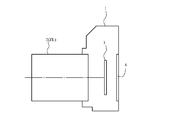
- the camera 1 is a so-called mirrorless camera with an interchangeable lens provided with the optical system ZL according to the present embodiment as the photographing lens 2.
- the light from an object (subject) (not shown) is collected by the photographing lens 2 and passed through an OLPF (Optical low pass filter) (not shown) on the imaging surface of the imaging unit 3.
- OLPF Optical low pass filter
- the subject image is photoelectrically converted by the photoelectric conversion element provided in the imaging unit 3, and the image of the subject is generated.
- This image is displayed on the EVF (Electronic viewfinder) 4 provided in the camera 1. This allows the photographer to observe the subject via the EVF4.
- EVF Electronic viewfinder
- the optical system ZL according to the present embodiment is mounted on a single-lens reflex type camera having a quick return mirror in the camera body and observing a subject by a finder optical system. Even in this case, the same effect as that of the camera 1 can be obtained.
- the optical device according to the present embodiment is provided with the optical system ZL having the above-described configuration, so that it is possible to realize an optical device that is compact and has various aberrations, particularly chromatic aberrations, satisfactorily corrected.
- the optical system ZL having a large two-group configuration of the front group GA and the rear group GB is shown, but the above configuration conditions and the like include the three groups, four groups, five groups, six groups, and seven groups. It can also be applied to other group configurations. Further, a configuration in which a lens or a lens group is added on the most object side or a configuration in which a lens or a lens group is added on the most image side may be used. Further, the lens group refers to a portion having at least one lens separated by an air interval that changes at the time of magnification change.
- a single lens group, a plurality of lens groups, or a partial lens group may be moved in the optical axis direction to focus on a short-distance object from an infinity object.
- the focusing lens group can also be applied to autofocus, and is also suitable for driving a motor (such as an ultrasonic motor) for autofocus.
- a motor such as an ultrasonic motor
- the lens group or partial lens group is moved so as to have a component in the direction perpendicular to the optical axis, or is rotationally moved (swinged) in the in-plane direction including the optical axis to correct image blur caused by camera shake.
- It may be a group of anti-vibration lenses.
- the lens surface may be formed of a spherical surface or a flat surface, or may be formed of an aspherical surface.
- the lens surface is spherical or flat, lens processing and assembly adjustment are facilitated, and deterioration of optical performance due to errors in processing and assembly adjustment is prevented, which is preferable. Further, even if the image plane is deviated, the depiction performance is less deteriorated, which is preferable.
- the lens surface is aspherical
- the aspherical surface is an aspherical surface formed by grinding, a glass mold aspherical surface formed by forming glass into an aspherical shape, or a composite aspherical surface formed by forming resin on the glass surface into an aspherical shape. Any aspherical surface may be used.
- the lens surface may be a diffraction surface, and the lens may be a refractive index distribution type lens (GRIN lens) or a plastic lens.
- GRIN lens refractive index distribution type lens
- the aperture diaphragm S is preferably arranged in the rear group GB (for example, the object side of the focusing group Gf), but the role may be substituted by the frame of the lens without providing the member as the aperture diaphragm. good.
- each lens surface may be provided with an antireflection film having high transmittance in a wide wavelength range in order to reduce flare and ghost and achieve high optical performance with high contrast.
- optical system ZL of the present embodiment has a magnification ratio of about 1.2 to 4.0 times.
- each lens is arranged, and a front group GA and a rear group GB including a diffraction lens Lfp are prepared (step S100), and the distance between each lens group is changed when the magnification of these lens groups is changed. (Step S200). Furthermore, the arrangement is made so as to satisfy the condition according to the above-mentioned conditional expression (step S300).
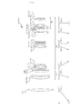
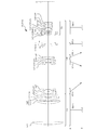
- FIG. 1, FIG. 3, FIG. 5, and FIG. 7 are cross-sectional views showing the configuration and refractive power distribution of the optical systems ZL (ZL1 to ZL4) according to the first to fourth embodiments. Further, in the lower part of the cross-sectional view of these optical systems ZL1 to ZL4, along the optical axis of each lens group G1 to G6 or G7 when scaling from the wide-angle end state (W) to the telephoto end state (T). The direction of movement is indicated by an arrow.
- phase shape ⁇ of the diffraction plane D is represented by the following equation (a).
- ⁇ (h, n) (2 ⁇ / (n ⁇ ⁇ 0)) ⁇ (C2h 2 + C4h 4 ) (a)
- h Height in the direction perpendicular to the optical axis
- n Order of diffracted light
- the refractive power ⁇ D of the diffraction optical surface represented by the equation (a) for an arbitrary wavelength ⁇ and an arbitrary diffraction order m is expressed by the following equation (b) using the lowest phase coefficient C2. Will be done.
- the diffraction plane is marked with # on the right side of the plane number.
- FIG. 1 is a diagram showing a configuration of an optical system ZL1 according to a first embodiment.
- This optical system ZL1 includes, in order from the object side, a first lens group G1 having a positive refractive power and a diffraction lens Lpf which is a second lens group G2 having a positive refractive power and a diffraction surface D is formed. It is composed of a front group GA and a rear group GB. Further, the rear group GB includes a third lens group G3 having a negative refractive power, a fourth lens group G4 having a positive refractive power, and a fifth lens group G5 having a positive refractive power in order from the object side. It is composed of a sixth lens group G6 having a negative refractive power and a seventh lens group G7 having a negative refractive power in the final group GL.
- the first lens group G1 is composed of a biconvex positive lens L11.
- the second lens group G2 includes a diffractive lens Lpf in which a diffractive surface D is formed on the lens surface on the image side of the positive meniscus lens L21 whose convex surface faces the object side in order from the object side, and a biconvex positive lens L22. It is composed of a bonded negative lens in which a double concave negative lens L23 is joined.
- the third lens group G3 includes a bonded negative lens in which a negative meniscus lens L31 having a convex surface facing the object side and a positive meniscus lens L32 having a convex surface facing the object side are joined in order from the object side, and a bonded negative lens on the object side. It is composed of a bonded negative lens obtained by joining a positive meniscus lens L33 with a concave surface and a negative meniscus lens L34 with a concave surface facing the object side. Further, the fourth lens group G4 is composed of a bonded positive lens in which a negative meniscus lens L41 having a convex surface facing the object side and a biconvex positive lens L42 are joined in order from the object side.
- the fifth lens group G5 includes a bonded positive lens in which a biconvex positive lens L51 and a negative meniscus lens L52 having a concave surface facing the object side are joined in order from the object side, and a positive meniscus having a convex surface facing the object side. It is composed of a lens L53.
- the sixth lens group G6 is composed of both concave and negative lenses L61.
- the seventh lens group G7 includes a bonded positive lens, a biconcave negative lens L73, and a biconvex positive lens L74 in which a positive meniscus lens L71 having a concave surface facing the object side and a biconcave negative lens L72 are joined in this order from the object side.
- the aperture diaphragm S is arranged between the fifth lens group G5 and the sixth lens group G6.
- the distance between the first lens group G1 and the second lens group G2 increases, and the second lens group G2 and the third lens group G3
- the distance between the third lens group G3 and the fourth lens group G4 decreases, the distance between the fourth lens group G4 and the fifth lens group G5 increases, and the distance between the fifth lens group G5 and the aperture aperture increases.
- the third lens group G3, the fourth lens group G4, the fifth lens group G5, the aperture aperture S, and the sixth lens group G6 move in the optical axis direction. Further, at the time of scaling, the second lens group G2 and the seventh lens group G7 are fixed to the image plane.
- the optical system ZL1 is configured such that the sixth lens group G6 is set as the focusing group Gf and the focusing group Gf is moved to the image side to focus from an infinity object to a short-range object. ing.
- the junction positive lens in which the positive meniscus lens L71 and the biconcave negative lens L72 are joined and the biconcave negative lens L73 are designated as the vibration isolation group Gvr, and the vibration isolation is provided.
- the first specific negative lens Ln1 is the negative meniscus lens L61 of the sixth lens group G6
- the second specific negative lens Ln2 is the biconcave negative lens L72 of the seventh lens group G7
- the third The specific negative lens Ln3 is a negative meniscus lens L75 of the seventh lens group G7.
- Table 1 below lists the specifications of the optical system ZL1.
- f in the overall specifications is the focal length of the entire system
- FNO is the F number
- 2 ⁇ is the total angle of view
- Ymax is the maximum image height
- TL is the total length
- Bf is the back focus.
- the values of the wide-angle end state, the two intermediate focal length states, and the telephoto end state are shown.
- the total length TL represents the distance on the optical axis from the lens surface (first surface) on the most object side to the image surface I.
- the back focus Bf indicates the distance on the optical axis from the lens surface (the 38th surface in FIG. 1) on the image side to the image surface I.
- the first column m is the order (plane number) of the lens surfaces from the object side along the traveling direction of the light beam
- the second column r is the radius of curvature of each lens surface in the third column
- d is the distance (plane spacing) on the optical axis from each optical surface to the next optical surface
- the radius of curvature 0.0000 indicates a plane
- the refractive index of air 1.000000 is omitted.
- the focal length of the lens group indicates the starting surface and the focal length of each of the first to seventh lens groups G1 to G7.
- mm is generally used as the unit of the focal length f, the radius of curvature r, the surface spacing d, and other lengths listed in all the following specification values, but the optical system is proportionally expanded or proportional. It is not limited to this because the same optical performance can be obtained even if the reduction is performed. Further, the description of these symbols and the description of the specification table are the same in the following examples.
- the fifth surface is a diffraction surface.
- Table 2 below shows the diffraction plane data, that is, the design wavelength ⁇ 0, the order n, and the values of the phase coefficients C2 and C4.
- the axial air gap d6 between the aperture S and the sixth lens group G6 and the axial air gap d7 between the sixth lens group G6 and the seventh lens group G7 change during magnification and focusing.
- Table 3 shows the variable intervals at each focal length in the wide-angle end state, intermediate focal length state, and telephoto end state at the time of focusing on an infinity object, focusing on a short-range object, and focusing on the closest object, respectively. Indicates a value.
- f indicates the focal length
- ⁇ indicates the magnification
- d0 indicates the distance from the first surface to the object. This description is the same in the following examples.
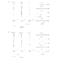
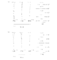
- FIG. 2 shows various aberration diagrams of the optical system ZL1 in the wide-angle end state and the telephoto end state.
- FNO indicates an F number
- Y indicates an image height.
- the spherical aberration diagram shows the value of the F number corresponding to the maximum aperture
- the astigmatism diagram and the distortion diagram show the maximum image height
- the transverse aberration diagram shows the value of each image height.
- the solid line shows the sagittal image plane and the broken line shows the meridional image plane.
- this optical system ZL1 satisfactorily corrects various aberrations from the wide-angle end state to the telephoto end state and has excellent imaging performance.
- FIG. 3 is a diagram showing a configuration of an optical system ZL2 according to a second embodiment.
- the optical system ZL2 includes a first lens group G1 having a positive refractive power and a diffraction lens Lpf which is a second lens group G2 having a positive refractive power and has a diffraction surface D formed in this order from the object side. It is composed of a front group GA and a rear group GB. Further, the rear group GB includes a third lens group G3 having a negative refractive power, a fourth lens group G4 having a positive refractive power, and a fifth lens group G5 having a positive refractive power in order from the object side. It is composed of a sixth lens group G6 having a negative refractive power and a seventh lens group G7 having a negative refractive power in the final group GL.
- the first lens group G1 is composed of a biconvex positive lens L11.
- the second lens group G2 is a bonded negative lens in which a biconvex positive lens L21 and a biconcave negative lens L22 are joined in order from the object side, and an image side of a positive meniscus lens L23 with a convex surface facing the object side. It is composed of a diffractive lens Lpf in which a diffractive surface D is formed on the lens surface.
- the third lens group G3 includes a bonded negative lens in which a negative meniscus lens L31 having a convex surface facing the object side and a positive meniscus lens L32 having a convex surface facing the object side are joined in order from the object side, and a bonded negative lens on the object side. It is composed of a bonded negative lens obtained by joining a positive meniscus lens L33 with a concave surface and a negative meniscus lens L34 with a concave surface facing the object side. Further, the fourth lens group G4 is composed of a bonded positive lens in which a negative meniscus lens L41 having a convex surface facing the object side and a biconvex positive lens L42 are joined in order from the object side.
- the fifth lens group G5 includes a bonded positive lens in which a biconvex positive lens L51 and a negative meniscus lens L52 having a concave surface facing the object side are joined in order from the object side, and a positive meniscus having a convex surface facing the object side. It is composed of a lens L53. Further, the sixth lens group G6 is composed of a negative meniscus lens L61 with a concave surface facing the object side.
- a bonded positive lens in which a biconvex positive lens L71 and a biconcave negative lens L72 are joined, a biconcave negative lens L73, a biconvex positive lens L74, and a concave surface on the object side are formed. It is composed of a bonded positive lens L75 joined with a facing negative meniscus lens L75, a positive meniscus lens L76 having a concave surface facing the object side, and a negative meniscus lens L77 having a concave surface facing the object side. Further, the aperture diaphragm S is arranged between the fifth lens group G5 and the sixth lens group G6.
- the distance between the first lens group G1 and the second lens group G2 increases, and the second lens group G2 and the third lens group G3
- the distance between the third lens group G3 and the fourth lens group G4 decreases, the distance between the fourth lens group G4 and the fifth lens group G5 increases, and the distance between the fifth lens group G5 and the aperture aperture increases.
- the second lens group G2, the third lens group G3, the fourth lens group G4, the fifth lens group G5, the aperture aperture S, and the sixth lens group G6 move in the optical axis direction. Further, at the time of scaling, the seventh lens group G7 is fixed with respect to the image plane.
- the optical system ZL2 is configured such that the sixth lens group G6 is set as the focusing group Gf and the focusing group Gf is moved to the image side to focus from an infinity object to a short-range object. ing.
- the junction positive lens in which the biconvex positive lens L71 and the biconcave negative lens L72 are joined and the biconcave negative lens L73 are designated as the vibration isolation group Gvr.
- the first specific negative lens Ln1 is the negative meniscus lens L61 of the sixth lens group G6
- the second specific negative lens Ln2 is the biconcave negative lens L72 of the seventh lens group G7
- the third The specific negative lens Ln3 is a negative meniscus lens L75 of the seventh lens group G7.
- Table 4 below lists the specifications of the optical system ZL2.
- the focal length of the lens group indicates the start surface and the focal length of each of the first to seventh lens groups G1 to G7.
- the eighth surface is a diffraction surface.
- Table 5 shows the diffraction plane data, that is, the design wavelength ⁇ 0, the order n, and the values of the phase coefficients C2 and C4.
- the axial air gap d6 between the aperture S and the sixth lens group G6 and the axial air gap d7 between the sixth lens group G6 and the seventh lens group G7 change during magnification and focusing.
- Table 6 shows the variable intervals at each focal length in the wide-angle end state, intermediate focal length state, and telephoto end state at the time of focusing on an infinity object, focusing on a short-range object, and focusing on the closest object, respectively. Indicates a value.
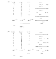
- FIG. 4 shows various aberration diagrams of the optical system ZL2 in the wide-angle end state and the telephoto end state. From these various aberration diagrams, it can be seen that this optical system ZL2 has excellent imaging performance by satisfactorily correcting various aberrations from the wide-angle end state to the telephoto end state.
- FIG. 5 is a diagram showing a configuration of an optical system ZL3 according to a third embodiment.
- This optical system ZL3 is composed of a front group GA including a diffraction lens Lpf which is a first lens group G1 having a positive refractive power and has a diffraction surface D formed in order from the object side, and a rear group GB.
- the rear group GB includes a second lens group G2 having a negative refractive power, a third lens group G3 having a positive refractive power, and a fourth lens group G4 having a positive refractive power in order from the object side.
- It is composed of a fifth lens group G5 having a negative refractive power and a sixth lens group G6 having a negative refractive power in the final group GL.
- the first lens group G1 is the image side of the biconvex positive lens L11, the positive meniscus lens L12 with the convex surface facing the object side, and the positive meniscus lens L13 with the convex surface facing the object side, in order from the object side. It is composed of a diffractive lens Lpf in which a diffractive surface D is formed on the lens surface of the lens, and a junction negative lens in which a positive meniscus lens L14 having a convex surface facing the object side and a negative meniscus lens L15 having a convex surface facing the object side are joined. ing.
- the second lens group G2 is a bonded negative lens in which a negative meniscus lens L21 having a convex surface facing the object side and a positive meniscus lens L22 having a convex surface facing the object side are joined in order from the object side, and both concave and negative lenses. It is composed of a lens L23.
- the third lens group G3 is composed of a biconvex positive lens L31 and a junction positive lens in which a biconvex positive lens L32 and a negative meniscus lens L33 with a concave surface facing the object side are joined in order from the object side. There is.
- the fourth lens group G4 is composed of a bonded positive lens in which a negative meniscus lens L41 having a convex surface facing the object side and a positive meniscus lens L42 having a convex surface facing the object side are joined in order from the object side.
- the fifth lens group G5 is composed of a negative meniscus lens L51 having a convex surface facing the object side.
- the sixth lens group G6 in order from the object side, a junction negative lens in which a biconvex positive lens L61 and a biconcave negative lens L62 are joined, a biconcave negative lens L63, a biconvex positive lens L64, and a concave surface on the object side are formed.
- the distance between the first lens group G1 and the second lens group G2 increases, and the second lens group G2 and the third lens group G3
- the distance between the third lens group G3 and the fourth lens group G4 increases, and the distance between the fourth lens group G4 and the fifth lens group G5 decreases.
- the third lens group G3 and the fourth lens group G4 move in the optical axis direction. Further, at the time of scaling, the first lens group G1, the fifth lens group G5, the sixth lens group G6, and the aperture diaphragm S are fixed with respect to the image plane.
- the optical system ZL3 is configured such that the fifth lens group G5 is set as the focusing group Gf and the focusing group Gf is moved to the image side to focus from an infinity object to a short-range object. ing.
- the junction negative lens in which the biconvex positive lens L61 and the biconcave negative lens L62 are joined and the biconcave negative lens L63 are designated as the vibration isolation group Gvr.
- the first specific negative lens Ln1 is the negative meniscus lens L51 of the fifth lens group G5
- the second specific negative lens Ln2 is the biconcave negative lens L62 of the sixth lens group G6
- the specific negative lens Ln3 is a negative meniscus lens L65 of the sixth lens group G6.
- Table 7 below lists the specifications of the optical system ZL3.
- the lens group focal lengths indicate the start surfaces and focal lengths of the first to sixth lens groups G1 to G6, respectively.
- the seventh surface is a diffraction surface.
- Table 8 shows the diffraction plane data, that is, the design wavelength ⁇ 0, the order n, and the values of the phase coefficients C2 and C4.
- the axial air spacing d6 between the 5 lens group G5 and the 6th lens group G6 changes upon scaling or focusing.
- Table 9 shows the variable intervals at each focal length in the wide-angle end state, intermediate focal length state, and telephoto end state at the time of focusing on an infinity object, focusing on a short-range object, and focusing on the closest object, respectively. Indicates a value.
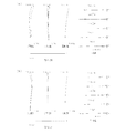
- FIG. 6 shows various aberration diagrams of the optical system ZL3 in the wide-angle end state and the telephoto end state. From these various aberration diagrams, it can be seen that this optical system ZL3 has excellent imaging performance by satisfactorily correcting various aberrations from the wide-angle end state to the telephoto end state.
- FIG. 7 is a diagram showing a configuration of an optical system ZL4 according to a fourth embodiment.
- This optical system ZL4 is composed of a front group GA including a diffraction lens Lpf which is a first lens group G1 having a positive refractive power and has a diffraction surface D formed in order from the object side, and a rear group GB.
- the rear group GB includes a second lens group G2 having a negative refractive power, a third lens group G3 having a positive refractive power, and a fourth lens group G4 having a positive refractive power in order from the object side.
- It is composed of a fifth lens group G5 having a negative refractive power and a sixth lens group G6 having a negative refractive power in the final group GL.
- the diffraction plane D is formed on the image side lens surface of the biconvex positive lens L11 and the positive meniscus lens L12 with the convex surface facing the object side in order from the object side. It is composed of a lens Lpf and a bonded negative lens in which a positive meniscus lens L13 having a convex surface facing the object side and a negative meniscus lens L14 having a convex surface facing the object side are joined.
- the second lens group G2 is a bonded negative lens in which a negative meniscus lens L21 having a convex surface facing the object side and a positive meniscus lens L22 having a convex surface facing the object side are joined in order from the object side, and both concave and negative lenses. It is composed of a lens L23.
- the third lens group G3 is composed of a biconvex positive lens L31 and a junction positive lens in which a biconvex positive lens L32 and a biconcave negative lens L33 are joined in order from the object side.
- the fourth lens group G4 is composed of a bonded positive lens in which a negative meniscus lens L41 having a convex surface facing the object side and a positive meniscus lens L42 having a convex surface facing the object side are joined in order from the object side.
- the fifth lens group G5 is composed of a negative meniscus lens L51 having a convex surface facing the object side.
- the sixth lens group G6 in order from the object side, a junction negative lens in which a biconvex positive lens L61 and a biconcave negative lens L62 are joined, a biconcave negative lens L63, a biconvex positive lens L64, and a concave surface on the object side are formed.
- the distance between the first lens group G1 and the second lens group G2 increases, and the second lens group G2 and the third lens group G3
- the distance between the third lens group G3 and the fourth lens group G4 increases, and the distance between the fourth lens group G4 and the fifth lens group G5 decreases.
- the third lens group G3 and the fourth lens group G4 move in the optical axis direction. Further, at the time of scaling, the first lens group G1, the fifth lens group G5, the sixth lens group G6, and the aperture diaphragm S are fixed with respect to the image plane.
- the optical system ZL4 is configured such that the fifth lens group G5 is set as the focusing group Gf and the focusing group Gf is moved to the image side to focus from an infinity object to a short-range object. ing.
- the junction negative lens in which the biconvex positive lens L61 and the biconcave negative lens L62 are joined and the biconcave negative lens L63 are designated as the vibration isolation group Gvr.
- the first specific negative lens Ln1 is the negative meniscus lens L51 of the fifth lens group G5
- the second specific negative lens Ln2 is the biconcave negative lens L62 of the sixth lens group G6
- the specific negative lens Ln3 is a negative meniscus lens L65 of the sixth lens group G6.
- Table 10 below lists the values of the specifications of the optical system ZL4.
- the lens group focal lengths indicate the start surfaces and focal lengths of the first to sixth lens groups G1 to G6, respectively.
- the fifth surface is a diffraction surface.
- Table 11 shows the diffraction plane data, that is, the design wavelength ⁇ 0, the order n, and the values of the phase coefficients C2 and C4.
- the axial air spacing d6 between the 5 lens group G5 and the 6th lens group G6 changes upon scaling or focusing.
- Table 12 shows the variable intervals at each focal length in the wide-angle end state, intermediate focal length state, and telephoto end state at the time of focusing on an infinity object, focusing on a short-range object, and focusing on the closest object, respectively. Indicates a value.
- FIG. 8 shows various aberration diagrams of the optical system ZL4 in the wide-angle end state and the telephoto end state. From these various aberration diagrams, it can be seen that this optical system ZL4 has excellent imaging performance by satisfactorily correcting various aberrations from the wide-angle end state to the telephoto end state.
Landscapes
- Physics & Mathematics (AREA)
- General Physics & Mathematics (AREA)
- Optics & Photonics (AREA)
- Lenses (AREA)
Abstract
Description
0.130 < TLpf/TLt < 0.500
但し、
TLt:望遠端状態における光学系の光学全長
TLpf:望遠端状態における光学系の最も物体側のレンズ面から回折面までの光軸上の距離
0.130 < TLpf/TLt < 0.500
但し、
TLt:望遠端状態における光学系の光学全長
TLpf:望遠端状態における光学系の最も物体側のレンズ面から回折面までの光軸上の距離
但し、
TLt:望遠端状態における光学系ZLの光学全長
TLpf:望遠端状態における光学系ZLの最も物体側のレンズ面から回折面Dまでの光軸上の距離
但し、
fw:広角端状態における光学系ZLの全系の焦点距離
Bfw:広角端状態における光学系ZLのバックフォーカス
但し、
fw:広角端状態における光学系ZLの全系の焦点距離
f1:光学系ZLの最も物体側に配置されたレンズ群の焦点距離
但し、
ft:望遠端状態における光学系ZLの全系の焦点距離
f1:光学系ZLの最も物体側に配置されたレンズ群の焦点距離
但し、
fL1:光学系ZLの最も物体側に配置されたレンズの焦点距離
f1:光学系ZLの最も物体側に配置されたレンズ群の焦点距離
但し、
ft:望遠端状態における光学系ZLの全系の焦点距離
TLt:望遠端状態における光学系ZLの光学全長
但し、
fObt:望遠端状態における、光学系ZLの開口絞りSより物体側の合成焦点距離
fImt:望遠端状態における、光学系ZLの開口絞りSより像側の合成焦点距離
但し、
νdF:合焦群Gfの第1特定負レンズLn1の媒質のd線に対するアッベ数
但し、
ft:望遠端状態における光学系ZLの全系の焦点距離
fLPF:回折レンズLpfの焦点距離
但し、
fA:前群GAの焦点距離
fLPF:回折レンズLpfの焦点距離
但し、
φD:回折面Dの主波長に対する屈折力
但し、
νdVR:防振群Gvrに含まれる第2特定負レンズLn2の媒質のd線に対するアッベ数
但し、
θgFr:後群GBに含まれる第3特定負レンズLn3の媒質の部分分散比
νdr:後群GBに含まれる第3特定負レンズLn3の媒質のd線に対するアッベ数
但し、
2ωw:広角端状態における光学系ZLの全画角
但し、
2ωt:望遠端状態における光学系ZLの全画角
但し、
h:光軸に対する垂直方向の高さ
n:回折光の次数
λ0:設計波長
Ci:位相係数(i=2,4)
図1は、第1実施例に係る光学系ZL1の構成を示す図である。この光学系ZL1は、物体側から順に、正の屈折力を有する第1レンズ群G1と、正の屈折力を有する第2レンズ群G2であって回折面Dが形成された回折レンズLpfを含む前群GAと、後群GBとから構成されている。また、後群GBは、物体側から順に、負の屈折力を有する第3レンズ群G3と、正の屈折力を有する第4レンズ群G4と、正の屈折力を有する第5レンズ群G5と、負の屈折力を有する第6レンズ群G6と、最終群GLであって負の屈折力を有する第7レンズ群G7とから構成されている。
[全体諸元]
広角端状態 中間焦点距離状態 望遠端状態
f = 205.000 ~ 300.000 ~ 400.000 ~ 486.800
FNO = 5.80 ~ 5.80 ~ 5.80 ~ 5.80
2ω(°) = 12.20 ~ 8.10 ~ 6.10 ~ 5.00
Ymax = 21.700 ~ 21.700 ~ 21.700 ~ 21.700
TL(空気換算長)= 309.985 ~ 346.860 ~ 371.010 ~ 386.088
Bf(空気換算長)= 46.220 ~ 46.220 ~ 46.220 ~ 46.220
[レンズデータ]
m r d nd νd
物面 ∞
1 254.0785 7.3000 1.487490 70.32
2 -849.8826 d1
3 100.1717 7.9000 1.516800 64.13
4 1236.3929 0.2000 1.527800 33.36
5# 1236.3929 0.3000 1.557147 49.98
6 1236.3929 1.5298
7 103.1253 7.6000 1.487490 70.32
8 -543.2044 2.2000 1.834000 37.18
9 103.4183 d2
10 214.9015 1.7000 1.603110 60.69
11 42.4820 3.8233 1.755200 27.57
12 69.2113 5.3961
13 -109.6455 3.6450 1.603420 38.03
14 -53.8051 1.6000 1.603110 60.69
15 -777.5523 d3
16 122.1606 1.6000 1.846660 23.80
17 79.4358 6.5000 1.497820 82.57
18 -109.5364 d4
19 100.2140 5.2000 1.487490 70.32
20 -97.6279 1.3000 1.834810 42.73
21 -763.2390 0.2000
22 78.1823 3.4000 1.497820 82.57
23 588.3269 d5
24 0.0000 d6 開口絞りS
25 -523.2367 1.2000 1.497820 82.57
26 41.4358 d7
27 -2692.1361 3.4000 1.717360 29.57
28 -39.0458 1.1000 1.487490 70.32
29 149.9024 2.8144
30 -83.9778 1.1000 1.834810 42.73
31 80.6792 2.2000
32 70.4993 6.1517 1.517420 52.20
33 -37.9968 1.3000 1.846660 23.80
34 -49.9102 28.4592
35 133.8635 3.9297 1.581440 40.98
36 -200.0000 12.2904
37 -72.2377 1.4000 1.834810 42.73
38 -200.0000 46.2202
像面 ∞
[レンズ群焦点距離]
レンズ群 始面 焦点距離
第1レンズ群 1 402.114
第2レンズ群 3 672.552
第3レンズ群 10 -110.137
第4レンズ群 16 142.197
第5レンズ群 19 126.943
第6レンズ群 25 -77.072
第7レンズ群 27 -2179.462
[回折面データ]
m λ0 n C2 C4
5 587.562 1.0 -3.29833E-05 1.41580E-09
[可変間隔データ]
-無限遠物体合焦時-
広角端状態 中間焦点距離状態 望遠端状態
f 205.000 300.000 400.000 486.800
d0 ∞ ∞ ∞ ∞
d1 15.1923 52.1496 76.2445 91.1517
d2 5.2390 19.4434 33.9175 46.4758
d3 71.7334 41.5723 18.0905 2.0000
d4 2.0000 15.8305 28.1619 40.3132
d5 22.4098 19.8129 13.4769 3.1339
d6 10.6047 6.9254 4.2307 3.6163
d7 9.8166 18.1202 23.9075 26.4376
-近距離物体合焦時-
広角端状態 中間焦点距離状態 望遠端状態
β -0.0333 -0.0333 -0.0333 -0.0333
d0 6028.2440 8807.2339 11748.6002 14296.9264
d1 15.1923 52.1496 76.2445 91.1517
d2 5.2390 19.4434 33.9175 46.4758
d3 71.7334 41.5723 18.0905 2.0000
d4 2.0000 15.8305 28.1619 40.3132
d5 22.4098 19.8129 13.4769 3.1339
d6 12.0254 8.7926 6.5524 6.3635
d7 8.3959 16.2530 21.5858 23.6905
-最至近物体合焦時-
広角端状態 中間焦点距離状態 望遠端状態
β -0.1015 -0.1457 -0.1901 -0.2253
d0 1890.0152 1853.1399 1828.9896 1813.9116
d1 15.1923 52.1496 76.2445 91.1517
d2 5.2390 19.4434 33.9175 46.4758
d3 71.7334 41.5723 18.0905 2.0000
d4 2.0000 15.8305 28.1619 40.3132
d5 22.4098 19.8129 13.4769 3.1339
d6 15.0280 15.4635 18.5543 24.5225
d7 5.3933 9.5820 9.5840 5.5315
図3は、第2実施例に係る光学系ZL2の構成を示す図である。この光学系ZL2は、物体側から順に、正の屈折力を有する第1レンズ群G1と、正の屈折力を有する第2レンズ群G2であって回折面Dが形成された回折レンズLpfを含む前群GAと、後群GBとから構成されている。また、後群GBは、物体側から順に、負の屈折力を有する第3レンズ群G3と、正の屈折力を有する第4レンズ群G4と、正の屈折力を有する第5レンズ群G5と、負の屈折力を有する第6レンズ群G6と、最終群GLであって負の屈折力を有する第7レンズ群G7とから構成されている。
[全体諸元]
広角端状態 中間焦点距離状態 望遠端状態
f = 205.000 ~ 300.000 ~ 400.000 ~ 486.800
FNO = 5.80 ~ 5.80 ~ 5.80 ~ 5.80
2ω(°) = 12.20 ~ 8.10 ~ 6.10 ~ 5.00
Ymax = 21.700 ~ 21.700 ~ 21.700 ~ 21.700
TL(空気換算長)= 309.991 ~ 348.121 ~ 376.459 ~ 395.024
Bf(空気換算長)= 53.850 ~ 53.850 ~ 53.850 ~ 53.850
[レンズデータ]
m r d nd νd
物面 ∞
1 282.6354 7.7000 1.487490 70.32
2 -642.2659 d1
3 128.8725 8.5000 1.487490 70.32
4 -246.4894 2.9000 1.834000 37.18
5 218.4075 12.4524
6 128.3795 6.6000 1.516800 64.13
7 664.6127 0.2000 1.527800 33.36
8# 664.6127 0.3000 1.557147 49.98
9 664.6127 d2
10 221.3422 1.7000 1.593490 67.00
11 41.8416 3.6079 1.737999 32.33
12 69.1709 5.1938
13 -88.1369 3.5380 1.620040 36.40
14 -46.7983 1.6000 1.593490 67.00
15 -345.4650 d3
16 116.6629 1.6000 1.854779 24.80
17 70.1121 7.0000 1.497820 82.57
18 -94.8648 d4
19 109.7141 5.6000 1.487490 70.32
20 -89.4788 1.3000 1.834810 42.73
21 -759.2096 0.2000
22 66.2440 3.8000 1.497820 82.57
23 533.5964 d5
24 0.0000 d6 開口絞りS
25 458.6915 1.2000 1.497820 82.57
26 37.7676 d7
27 410.7201 3.8000 1.698950 30.13
28 -41.4786 1.1000 1.497820 82.57
29 77.0949 2.0909
30 -104.9331 1.1000 1.763850 48.49
31 57.8594 2.2000
32 60.7986 6.4494 1.647690 33.72
33 -39.3235 1.3000 1.945944 17.98
34 -59.9206 14.7446
35 -519.7257 4.0124 1.548140 45.51
36 -52.6602 1.8102
37 -49.5416 1.7000 1.953750 32.33
38 -150.7732 53.8499
像面 ∞
[レンズ群焦点距離]
レンズ群 始面 焦点距離
第1レンズ群 1 403.708
第2レンズ群 3 497.543
第3レンズ群 10 -110.064
第4レンズ群 16 134.649
第5レンズ群 19 122.017
第6レンズ群 25 -82.752
第7レンズ群 27 -266.950
[回折面データ]
m λ0 n C2 C4
8 587.562 1.0 -4.88662E-05 8.54150E-10
[可変間隔データ]
-無限遠物体合焦時-
広角端状態 中間焦点距離状態 望遠端状態
f 205.000 300.000 400.000 486.800
d0 ∞ ∞ ∞ ∞
d1 35.0863 72.7170 96.8729 111.7476
d2 4.0000 18.4016 34.3631 49.6023
d3 58.6232 31.9700 13.8407 2.0000
d4 2.0000 12.1985 19.3551 24.8875
d5 22.9315 19.0854 12.3877 2.1508
d6 9.6174 6.1513 3.2290 3.0000
d7 8.5852 18.4505 27.2617 32.4878
-近距離物体合焦時-
広角端状態 中間焦点距離状態 望遠端状態
β -0.0333 -0.0333 -0.0333 -0.0333
d0 5993.6460 8763.3788 11693.9147 14236.8500
d1 35.0863 72.7170 96.8729 111.7476
d2 4.0000 18.4016 34.3631 49.6023
d3 58.6232 31.9700 13.8407 2.0000
d4 2.0000 12.1985 19.3551 24.8875
d5 22.9315 19.0854 12.3877 2.1508
d6 11.1793 8.0983 5.5065 5.5787
d7 7.0233 16.5035 24.9842 29.9092
-最至近物体合焦時-
広角端状態 中間焦点距離状態 望遠端状態
β -0.0871 -0.1249 -0.1630 -0.1940
d0 2190.0093 2151.8789 2123.5408 2104.9764
d1 35.0863 72.7170 96.8729 111.7476
d2 4.0000 18.4016 34.3631 49.6023
d3 58.6232 31.9700 13.8407 2.0000
d4 2.0000 12.1985 19.3551 24.8875
d5 22.9315 19.0854 12.3877 2.1508
d6 13.7981 13.7984 15.2346 19.6692
d7 4.4045 10.8034 15.2561 15.8186
図5は、第3実施例に係る光学系ZL3の構成を示す図である。この光学系ZL3は、物体側から順に、正の屈折力を有する第1レンズ群G1であって回折面Dが形成された回折レンズLpfを含む前群GAと、後群GBとから構成されている。また、後群GBは、物体側から順に、負の屈折力を有する第2レンズ群G2と、正の屈折力を有する第3レンズ群G3と、正の屈折力を有する第4レンズ群G4と、負の屈折力を有する第5レンズ群G5と、最終群GLであって負の屈折力を有する第6レンズ群G6とから構成されている。
[全体諸元]
広角端状態 中間焦点距離状態 望遠端状態
f = 306.000 ~ 375.000 ~ 450.000 ~ 588.000
FNO = 6.40 ~ 6.40 ~ 6.40 ~ 6.40
2ω(°) = 8.10 ~ 6.40 ~ 5.30 ~ 4.10
Ymax = 21.700 ~ 21.700 ~ 21.700 ~ 21.700
TL(空気換算長)= 329.948 ~ 329.948 ~ 329.948 ~ 329.948
Bf(空気換算長)= 52.139 ~ 52.139 ~ 52.139 ~ 52.139
[レンズデータ]
m r d nd νd
物面 ∞
1 223.0897 9.0000 1.487490 70.32
2 -2499.7170 0.2000
3 259.0655 6.0000 1.487490 70.32
4 809.7669 29.8001
5 72.6287 10.5000 1.516800 64.13
6 187.6069 0.2000 1.527800 33.36
7# 187.6069 0.3000 1.557147 49.98
8 187.6069 0.2000
9 73.2943 8.6000 1.487490 70.32
10 155.3551 3.3000 1.902650 35.72
11 58.1940 d1
12 2518.2275 2.3000 1.593190 67.90
13 38.8981 8.8000 1.620040 36.40
14 169.4898 4.1741
15 -128.2896 2.3000 1.593190 67.90
16 130.6010 d2
17 111.3992 6.8000 1.497820 82.57
18 -115.5330 0.2000
19 117.3443 6.6000 1.497820 82.57
20 -99.9337 2.2000 1.834810 42.73
21 -1722.6637 d3
22 46.2607 1.8000 1.834810 42.73
23 33.4269 7.3000 1.437001 95.10
24 921.5481 d4
25 0.0000 d5 開口絞りS
26 245.9026 1.2000 1.497820 82.57
27 34.7408 d6
28 128.5153 4.8000 1.647690 33.72
29 -26.3998 1.2000 1.593190 67.90
30 56.4530 2.2648
31 -99.9188 1.2000 1.834810 42.73
32 53.5072 2.1608
33 41.0489 6.2000 1.755200 27.57
34 -33.6117 1.2000 1.945944 17.98
35 -314.2067 1.0000
36 -397.2352 1.3000 1.834810 42.73
37 34.1457 7.2000 1.603420 38.03
38 -39.2481 0.2000
39 56.9659 7.0000 1.603420 38.03
40 -35.0081 1.3000 1.834810 42.73
41 94.5542 52.1387
像面 ∞
[レンズ群焦点距離]
レンズ群 始面 焦点距離
第1レンズ群 1 241.670
第2レンズ群 12 -83.460
第3レンズ群 17 98.299
第4レンズ群 22 169.346
第5レンズ群 26 -81.421
第6レンズ群 28 -144.655
[回折面データ]
m λ0 n C2 C4
8 587.562 1.0 -3.79176E-05 -5.49873E-10
[可変間隔データ]
-無限遠物体合焦時-
広角端状態 中間焦点距離状態 望遠端状態
f 306.000 375.000 450.000 588.000
d0 ∞ ∞ ∞ ∞
d1 8.2880 20.4670 29.9682 41.7344
d2 61.6784 43.6483 26.8374 2.0000
d3 2.0000 11.4752 24.3876 52.1668
d4 27.0009 23.3786 17.7734 3.0657
d5 3.5804 3.5804 3.5804 3.5804
d6 26.4619 26.4619 26.4619 26.4619
-近距離物体合焦時-
広角端状態 中間焦点距離状態 望遠端状態
β -0.0333 -0.0333 -0.0333 -0.0333
d0 8969.0498 11012.1338 13228.4896 17325.9277
d1 8.2880 20.4670 29.9682 41.7344
d2 61.6784 43.6483 26.8374 2.0000
d3 2.0000 11.4752 24.3876 52.1668
d4 27.0009 23.3786 17.7734 3.0657
d5 5.1948 5.5652 5.9727 6.7242
d6 24.8475 24.4771 24.0696 23.3181
-最至近物体合焦時-
広角端状態 中間焦点距離状態 望遠端状態
β -0.1058 -0.1281 -0.1520 -0.1916
d0 2670.0520 2670.0508 2670.0515 2670.0516
d1 8.2880 20.4670 29.9682 41.7344
d2 61.6784 43.6483 26.8374 2.0000
d3 2.0000 11.4752 24.3876 52.1668
d4 27.0009 23.3786 17.7734 3.0657
d5 8.8767 11.6424 15.4728 25.1573
d6 21.1656 18.3999 14.5695 4.8850
図7は、第4実施例に係る光学系ZL4の構成を示す図である。この光学系ZL4は、物体側から順に、正の屈折力を有する第1レンズ群G1であって回折面Dが形成された回折レンズLpfを含む前群GAと、後群GBとから構成されている。また、後群GBは、物体側から順に、負の屈折力を有する第2レンズ群G2と、正の屈折力を有する第3レンズ群G3と、正の屈折力を有する第4レンズ群G4と、負の屈折力を有する第5レンズ群G5と、最終群GLであって負の屈折力を有する第6レンズ群G6とから構成されている。
[全体諸元]
広角端状態 中間焦点距離状態 望遠端状態
f = 407.999 ~ 499.999 ~ 599.999 ~ 783.998
FNO = 8.10 ~ 8.10 ~ 8.10 ~ 8.10
2ω(°) = 6.10 ~ 5.00 ~ 4.10 ~ 3.10
Ymax = 21.700 ~ 21.700 ~ 21.700 ~ 21.700
TL(空気換算長)= 435.067 ~ 435.067 ~ 435.067 ~ 435.067
Bf(空気換算長)= 73.106 ~ 73.106 ~ 73.106 ~ 73.106
[レンズデータ]
m r d nd νd
物面 ∞
1 258.4345 10.0000 1.487490 70.32
2 -1168.9851 63.4972
3 115.6841 9.5000 1.516800 64.13
4 368.7797 0.2000 1.527800 33.36
5# 368.7797 0.3000 1.557147 49.98
6 368.7797 3.8039
7 105.0900 8.0000 1.487490 70.32
8 285.7295 3.4000 1.910822 35.25
9 100.3173 54.9337
10 4375.0065 2.4000 1.593190 67.90
11 50.4771 8.5000 1.654115 39.68
12 303.4262 3.9981
13 -191.8285 2.4000 1.593190 67.90
14 136.2524 2.4762
15 173.4580 6.8000 1.497820 82.57
16 -149.4370 0.2000
17 127.8783 6.9000 1.497820 82.57
18 -169.1970 2.4000 1.834810 42.73
19 934.1996 77.4827
20 63.0908 2.0000 1.834810 42.73
21 45.9742 7.0000 1.437001 95.10
22 1607.1068 3.0448
23 0.0000 3.5002 開口絞りS
24 242.6088 1.5000 1.497820 82.57
25 50.7283 34.1399
26 100.2153 5.0000 1.620040 36.40
27 -35.1813 1.2000 1.593190 67.90
28 49.8987 4.2135
29 -111.1526 1.2000 1.763850 48.49
30 72.5691 2.8158
31 51.6193 7.0000 1.740770 27.74
32 -39.2912 1.4000 1.945944 17.98
33 -178.7273 1.8453
34 -276.0919 1.8000 1.834810 42.73
35 41.3741 8.3000 1.603420 38.03
36 -53.4830 0.2097
37 108.8915 6.8000 1.603420 38.03
38 -43.1723 1.8000 1.834810 42.73
39 166.6667 73.1064
像面 ∞
[レンズ群焦点距離]
レンズ群 始面 焦点距離
第1レンズ群 1 314.735
第2レンズ群 10 -121.354
第3レンズ群 15 137.109
第4レンズ群 20 225.121
第5レンズ群 24 -129.177
第6レンズ群 26 -119.894
[回折面データ]
m λ0 n C2 C4
5 587.562 1.0 -3.12473E-05 -4.11319E-10
[可変間隔データ]
-無限遠物体合焦時-
広角端状態 中間焦点距離状態 望遠端状態
f 407.999 499.999 599.999 783.998
d0 ∞ ∞ ∞ ∞
d1 8.3177 25.1499 38.4172 54.9337
d2 88.0005 61.7682 37.4810 2.4762
d3 2.0000 17.2082 36.8435 77.4827
d4 39.6193 33.8128 25.1954 3.0448
d5 3.5002 3.5002 3.5002 3.5002
d6 34.1399 34.1399 34.1399 34.1399
-近距離物体合焦時-
広角端状態 中間焦点距離状態 望遠端状態
β -0.0333 -0.0333 -0.0333 -0.0333
d0 11966.7412 14693.1155 17646.8261 23098.6946
d1 8.3177 25.1499 38.4172 54.9337
d2 88.0005 61.7682 37.4810 2.4762
d3 2.0000 17.2082 36.8435 77.4827
d4 39.6193 33.8128 25.1954 3.0448
d5 5.6545 6.1493 6.6940 7.6989
d6 31.9856 31.4908 30.9461 29.9412
-最至近物体合焦時-
広角端状態 中間焦点距離状態 望遠端状態
β -0.1059 -0.1283 -0.1521 -0.1911
d0 3564.9328 3564.9313 3564.9330 3564.9327
d1 8.3177 25.1499 38.4172 54.9337
d2 88.0005 61.7682 37.4810 2.4762
d3 2.0000 17.2082 36.8435 77.4827
d4 39.6193 33.8128 25.1954 3.0448
d5 10.5885 14.3154 19.4917 32.6725
d6 27.0516 23.3247 18.1484 4.9676
第1実施例~第4実施例の条件式(1)~(15)の数値を以下に記載する。
(1)TLpf/TLt
(2)Bfw/fw
(3)f1/fw
(4)f1/ft
(5)f1/fL1
(6)TLt/ft
(7)(-fImt)/fObt
(8)νdF
(9)fLPF/ft
(10)fLPF/fA
(11)φD
(12)νdVR
(13)θgFr+0.00168×νdr
(14)2ωw[°]
(15)2ωt[°]
第1実施例 第2実施例 第3実施例 第4実施例
TLpf 106.552 150.100 55.800 85.012
TLt 386.088 395.024 329.948 435.067
fL1 402.114 403.708 420.590 443.933
fObt 182.902 171.829 200.278 253.280
fImt -73.630 -56.594 -46.257 -53.589
fLPF 207.586 297.738 218.553 315.650
fA 672.552 497.543 241.670 314.735
(1) 0.276 0.380 0.169 0.195
(2) 0.226 0.263 0.170 0.179
(3) 1.962 1.969 0.790 0.771
(4) 0.826 0.829 0.411 0.401
(5) 1.000 1.000 0.575 0.709
(6) 0.793 0.811 0.561 0.555
(7) 0.403 0.329 0.231 0.212
(8) 82.57 82.57 82.57 82.57
(9) 0.426 0.612 0.372 0.403
(10) 0.309 0.598 0.904 1.003
(11) 6.60E-05 9.77E-05 7.58E-05 6.25E-05
(12) 70.32 82.57 67.90 67.90
(13) 0.661 0.685 0.685 0.685
(14) 12.200 12.200 8.100 6.100
(15) 5.000 5.000 4.100 3.100
Lpf 回折レンズ D 回折面 GA 前群 GB 後群
G1 最も物体側に配置されたレンズ群(第1レンズ群) GL 最終群
Gf 合焦群 Gvr 防振群 S 開口絞り
L11 最も物体側に配置されたレンズ(第1レンズ)
Claims (20)
- 回折面が形成された回折レンズを含む前群と、
前記前群の像側に配置された後群と、を有し、
変倍に際し、各々のレンズ群の間隔が変化し、
次式の条件を満足する光学系。
0.130 < TLpf/TLt < 0.500
但し、
TLt:望遠端状態における前記光学系の光学全長
TLpf:望遠端状態における前記光学系の最も物体側のレンズ面から前記回折面までの光軸上の距離 - 次式の条件を満足する請求項1に記載の光学系。
Bfw/fw < 0.90
但し、
fw:広角端状態における前記光学系の全系の焦点距離
Bfw:広角端状態における前記光学系のバックフォーカス - 次式の条件を満足する請求項1または2に記載の光学系。
0.50 < f1/fw < 5.00
但し、
fw:広角端状態における前記光学系の全系の焦点距離
f1:前記光学系の最も物体側に配置されたレンズ群の焦点距離 - 次式の条件を満足する請求項1~3のいずれか一項に記載の光学系。
0.20 < f1/ft < 2.00
但し、
ft:望遠端状態における前記光学系の全系の焦点距離
f1:前記光学系の最も物体側に配置されたレンズ群の焦点距離 - 次式の条件を満足する請求項1~4のいずれか一項に記載の光学系。
0.30 < f1/fL1 < 1.50
但し、
fL1:前記光学系の最も物体側に配置されたレンズの焦点距離
f1:前記光学系の最も物体側に配置されたレンズ群の焦点距離 - 次式の条件を満足する請求項1~5のいずれか一項に記載の光学系。
0.40 < TLt/ft < 1.00
但し、
ft:望遠端状態における前記光学系の全系の焦点距離
TLt:望遠端状態における前記光学系の光学全長 - 開口絞りを有し、
次式の条件を満足する請求項1~6のいずれか一項に記載の光学系。
0.10 < (-fImt)/fObt < 0.60
但し、
fObt:望遠端状態における、前記光学系の前記開口絞りより物体側の合成焦点距離
fImt:望遠端状態における、前記光学系の前記開口絞りより像側の合成焦点距離 - 合焦に際し光軸方向に移動する合焦群を有し、
前記合焦群は、少なくとも1枚の負レンズを有し、
次式の条件を満足する請求項1~7のいずれか一項に記載の光学系。
60.00 < νdF
但し、
νdF:前記合焦群の前記負レンズの媒質のd線に対するアッベ数 - 次式の条件を満足する請求項1~8のいずれか一項に記載の光学系。
0.200 < fLPF/ft < 1.000
但し、
ft:望遠端状態における前記光学系の全系の焦点距離
fLPF:前記回折レンズの焦点距離 - 次式の条件を満足する請求項1~9のいずれか一項に記載の光学系。
0.100 < fLPF/fA < 2.000
但し、
fA:前記前群の焦点距離
fLPF:前記回折レンズの焦点距離 - 次式の条件を満足する請求項1~10のいずれか一項に記載の光学系。
2.0E-5 < φD < 2.0E-4
但し、
φD:前記回折面の主波長に対する屈折力 - 前記回折面は空気と接している請求項1~11のいずれか一項に記載の光学系。
- 前記回折面は、合焦に際し光軸方向に移動する合焦群より物体側に配置されている請求項1~12のいずれか一項に記載の光学系。
- 最も像側に、変倍に際し像面に対して固定される最終群を有する請求項1~13のいずれか一項に記載の光学系。
- 前記後群は、光軸と直交する方向の変位成分を持つように移動させる防振群を有し、
前記防振群は、次式の条件を満足する負レンズを少なくとも1枚有する請求項1~14のいずれか一項に記載の光学系。
56.00 < νdVR
但し、
νdVR:前記防振群に含まれる前記負レンズの媒質のd線に対するアッベ数 - 前記後群は、次式の条件を満足する負レンズを少なくとも1枚有する請求項1~15のいずれか一項に記載の光学系。
0.655 < θgFr+0.00168×νdr
但し、
θgFr:前記後群に含まれる前記負レンズの媒質の部分分散比
νdr:前記後群に含まれる前記負レンズの媒質のd線に対するアッベ数 - 次式の条件を満足する請求項1~16のいずれか一項に記載の光学系。
0.00° < 2ωw < 24.00°
但し、
2ωw:広角端状態における前記光学系の全画角 - 次式の条件を満足する請求項1~17のいずれか一項に記載の光学系。
0.00° < 2ωt < 10.00°
但し、
2ωt:望遠端状態における前記光学系の全画角 - 請求項1~18のいずれか一項に記載の光学系を有する光学機器。
- 回折面が形成された回折レンズを含む前群と、前記前群の像側に配置された後群と、を有する光学系の製造方法であって、
変倍に際し、各々のレンズ群の間隔が変化するように配置し、
次式の条件を満足するように配置する光学系の製造方法。
0.130 < TLpf/TLt < 0.500
但し、
TLt:望遠端状態における前記光学系の光学全長
TLpf:望遠端状態における前記光学系の最も物体側のレンズ面から前記回折面までの光軸上の距離
Priority Applications (3)
| Application Number | Priority Date | Filing Date | Title |
|---|---|---|---|
| JP2021565402A JP7324429B2 (ja) | 2019-12-20 | 2020-11-24 | 光学系、及び光学機器 |
| CN202080078047.3A CN114730066B (zh) | 2019-12-20 | 2020-11-24 | 光学系统以及光学设备 |
| US17/772,503 US12529874B2 (en) | 2019-12-20 | 2020-11-24 | Optical system, optical apparatus, and method for manufacturing optical system |
Applications Claiming Priority (2)
| Application Number | Priority Date | Filing Date | Title |
|---|---|---|---|
| JP2019230038 | 2019-12-20 | ||
| JP2019-230038 | 2019-12-20 |
Publications (1)
| Publication Number | Publication Date |
|---|---|
| WO2021124804A1 true WO2021124804A1 (ja) | 2021-06-24 |
Family
ID=76477237
Family Applications (1)
| Application Number | Title | Priority Date | Filing Date |
|---|---|---|---|
| PCT/JP2020/043565 Ceased WO2021124804A1 (ja) | 2019-12-20 | 2020-11-24 | 光学系、光学機器、及び光学系の製造方法 |
Country Status (4)
| Country | Link |
|---|---|
| US (1) | US12529874B2 (ja) |
| JP (1) | JP7324429B2 (ja) |
| CN (1) | CN114730066B (ja) |
| WO (1) | WO2021124804A1 (ja) |
Cited By (1)
| Publication number | Priority date | Publication date | Assignee | Title |
|---|---|---|---|---|
| JP2025002495A (ja) * | 2023-06-22 | 2025-01-09 | キヤノン株式会社 | ズームレンズ及びそれを有する撮像装置 |
Citations (8)
| Publication number | Priority date | Publication date | Assignee | Title |
|---|---|---|---|---|
| JP2000009999A (ja) * | 1998-06-19 | 2000-01-14 | Minolta Co Ltd | ズームレンズ |
| JP2002107624A (ja) * | 2000-09-29 | 2002-04-10 | Canon Inc | ズームレンズ及びそれを用いた光学機器 |
| JP2002131641A (ja) * | 2000-10-25 | 2002-05-09 | Canon Inc | ズームレンズ及びそれを用いた投影装置 |
| JP2002244044A (ja) * | 2001-02-19 | 2002-08-28 | Canon Inc | ズームレンズ及びそれを用いた光学機器 |
| JP2005352057A (ja) * | 2004-06-09 | 2005-12-22 | Canon Inc | ズームレンズ及びそれを有する撮像装置 |
| JP2015232674A (ja) * | 2014-06-11 | 2015-12-24 | キヤノン株式会社 | ズームレンズ及びそれを有する光学機器 |
| JP2016080877A (ja) * | 2014-10-17 | 2016-05-16 | キヤノン株式会社 | ズームレンズ及びそれを有する光学機器 |
| JP2019132919A (ja) * | 2018-01-30 | 2019-08-08 | キヤノン株式会社 | ズームレンズ及びそれを有する撮像装置 |
Family Cites Families (8)
| Publication number | Priority date | Publication date | Assignee | Title |
|---|---|---|---|---|
| JP3754805B2 (ja) * | 1996-09-19 | 2006-03-15 | キヤノン株式会社 | ズームレンズ及びそれを用いた光学機器 |
| US6639737B2 (en) * | 2000-10-25 | 2003-10-28 | Canon Kabushiki Kaisha | Zoom lens system and projection apparatus using the same |
| JP2011090099A (ja) * | 2009-10-21 | 2011-05-06 | Panasonic Corp | ズームレンズ系、交換レンズ装置、カメラシステム |
| JP2018010219A (ja) * | 2016-07-15 | 2018-01-18 | 株式会社ニコン | 変倍光学系、光学機器及び変倍光学系の製造方法 |
| JP6870230B2 (ja) * | 2016-07-27 | 2021-05-12 | 株式会社ニコン | 光学系及び光学機器 |
| JP2018097276A (ja) * | 2016-12-15 | 2018-06-21 | オリンパス株式会社 | 結像レンズ系及びそれを備えた撮像装置 |
| WO2018180359A1 (ja) * | 2017-03-28 | 2018-10-04 | 株式会社ニコン | 光学系、光学機器及び光学系の製造方法 |
| CN111465881B (zh) | 2017-12-15 | 2022-05-03 | 株式会社尼康 | 光学系统以及光学设备 |
-
2020
- 2020-11-24 US US17/772,503 patent/US12529874B2/en active Active
- 2020-11-24 WO PCT/JP2020/043565 patent/WO2021124804A1/ja not_active Ceased
- 2020-11-24 JP JP2021565402A patent/JP7324429B2/ja active Active
- 2020-11-24 CN CN202080078047.3A patent/CN114730066B/zh active Active
Patent Citations (8)
| Publication number | Priority date | Publication date | Assignee | Title |
|---|---|---|---|---|
| JP2000009999A (ja) * | 1998-06-19 | 2000-01-14 | Minolta Co Ltd | ズームレンズ |
| JP2002107624A (ja) * | 2000-09-29 | 2002-04-10 | Canon Inc | ズームレンズ及びそれを用いた光学機器 |
| JP2002131641A (ja) * | 2000-10-25 | 2002-05-09 | Canon Inc | ズームレンズ及びそれを用いた投影装置 |
| JP2002244044A (ja) * | 2001-02-19 | 2002-08-28 | Canon Inc | ズームレンズ及びそれを用いた光学機器 |
| JP2005352057A (ja) * | 2004-06-09 | 2005-12-22 | Canon Inc | ズームレンズ及びそれを有する撮像装置 |
| JP2015232674A (ja) * | 2014-06-11 | 2015-12-24 | キヤノン株式会社 | ズームレンズ及びそれを有する光学機器 |
| JP2016080877A (ja) * | 2014-10-17 | 2016-05-16 | キヤノン株式会社 | ズームレンズ及びそれを有する光学機器 |
| JP2019132919A (ja) * | 2018-01-30 | 2019-08-08 | キヤノン株式会社 | ズームレンズ及びそれを有する撮像装置 |
Cited By (2)
| Publication number | Priority date | Publication date | Assignee | Title |
|---|---|---|---|---|
| JP2025002495A (ja) * | 2023-06-22 | 2025-01-09 | キヤノン株式会社 | ズームレンズ及びそれを有する撮像装置 |
| JP7721596B2 (ja) | 2023-06-22 | 2025-08-12 | キヤノン株式会社 | ズームレンズ及びそれを有する撮像装置 |
Also Published As
| Publication number | Publication date |
|---|---|
| US12529874B2 (en) | 2026-01-20 |
| CN114730066A (zh) | 2022-07-08 |
| CN114730066B (zh) | 2023-09-22 |
| US20220382026A1 (en) | 2022-12-01 |
| JPWO2021124804A1 (ja) | 2021-06-24 |
| JP7324429B2 (ja) | 2023-08-10 |
Similar Documents
| Publication | Publication Date | Title |
|---|---|---|
| JP7021683B2 (ja) | ズームレンズおよび光学機器 | |
| JP2011017912A (ja) | 変倍光学系、この変倍光学系を備える光学機器、及び、変倍光学系の製造方法 | |
| CN116324567B (zh) | 变倍光学系统、光学设备及变倍光学系统的制造方法 | |
| WO2009139253A1 (ja) | 変倍光学系、この変倍光学系を備えた光学機器、及び、変倍光学系の製造方法 | |
| WO2019097669A1 (ja) | 変倍光学系、光学装置、変倍光学系の製造方法 | |
| WO2018012624A1 (ja) | 変倍光学系、光学機器及び変倍光学系の製造方法 | |
| JP6857305B2 (ja) | 変倍光学系及び光学機器 | |
| JP6221451B2 (ja) | ズームレンズ、光学機器及びズームレンズの製造方法 | |
| WO2014024962A1 (ja) | ズームレンズ、光学装置、ズームレンズの製造方法 | |
| JP2021105747A (ja) | 光学系および光学機器 | |
| JP2022036249A (ja) | 変倍光学系及び光学機器 | |
| CN115004074B (zh) | 变倍光学系统以及光学设备 | |
| CN114286959B (zh) | 变倍光学系统以及光学设备 | |
| CN114341696B (zh) | 光学系统以及光学设备 | |
| JP6784952B2 (ja) | 光学系及び光学機器 | |
| JP2018165818A (ja) | 光学系、光学機器及び光学系の製造方法 | |
| JP2016156941A (ja) | レンズ系、光学機器及びレンズ系の製造方法 | |
| JP7217858B2 (ja) | 光学系、光学機器 | |
| CN118215869A (zh) | 光学系统、光学设备以及光学系统的制造方法 | |
| JP6784950B2 (ja) | 光学系及び光学機器 | |
| JP6645498B2 (ja) | 変倍光学系及び光学機器 | |
| JP6880544B2 (ja) | ズームレンズおよび光学機器 | |
| JP7324429B2 (ja) | 光学系、及び光学機器 | |
| JP6524703B2 (ja) | ズームレンズ、光学機器及びズームレンズの製造方法 | |
| JP7709678B2 (ja) | 光学系及び光学機器 |
Legal Events
| Date | Code | Title | Description |
|---|---|---|---|
| 121 | Ep: the epo has been informed by wipo that ep was designated in this application |
Ref document number: 20902236 Country of ref document: EP Kind code of ref document: A1 |
|
| ENP | Entry into the national phase |
Ref document number: 2021565402 Country of ref document: JP Kind code of ref document: A |
|
| NENP | Non-entry into the national phase |
Ref country code: DE |
|
| 122 | Ep: pct application non-entry in european phase |
Ref document number: 20902236 Country of ref document: EP Kind code of ref document: A1 |
|
| WWG | Wipo information: grant in national office |
Ref document number: 17772503 Country of ref document: US |