WO2021112082A1 - 平板状成形体および多層体 - Google Patents
平板状成形体および多層体 Download PDFInfo
- Publication number
- WO2021112082A1 WO2021112082A1 PCT/JP2020/044671 JP2020044671W WO2021112082A1 WO 2021112082 A1 WO2021112082 A1 WO 2021112082A1 JP 2020044671 W JP2020044671 W JP 2020044671W WO 2021112082 A1 WO2021112082 A1 WO 2021112082A1
- Authority
- WO
- WIPO (PCT)
- Prior art keywords
- shaped molded
- flat plate
- molded product
- bisphenol
- less
- Prior art date
- Legal status (The legal status is an assumption and is not a legal conclusion. Google has not performed a legal analysis and makes no representation as to the accuracy of the status listed.)
- Ceased
Links
- 0 CC1=*CC(*)C=C1* Chemical compound CC1=*CC(*)C=C1* 0.000 description 3
Images

Classifications
-
- B—PERFORMING OPERATIONS; TRANSPORTING
- B32—LAYERED PRODUCTS
- B32B—LAYERED PRODUCTS, i.e. PRODUCTS BUILT-UP OF STRATA OF FLAT OR NON-FLAT, e.g. CELLULAR OR HONEYCOMB, FORM
- B32B27/00—Layered products comprising a layer of synthetic resin
- B32B27/36—Layered products comprising a layer of synthetic resin comprising polyesters
-
- B—PERFORMING OPERATIONS; TRANSPORTING
- B32—LAYERED PRODUCTS
- B32B—LAYERED PRODUCTS, i.e. PRODUCTS BUILT-UP OF STRATA OF FLAT OR NON-FLAT, e.g. CELLULAR OR HONEYCOMB, FORM
- B32B7/00—Layered products characterised by the relation between layers; Layered products characterised by the relative orientation of features between layers, or by the relative values of a measurable parameter between layers, i.e. products comprising layers having different physical, chemical or physicochemical properties; Layered products characterised by the interconnection of layers
- B32B7/02—Physical, chemical or physicochemical properties
- B32B7/023—Optical properties
-
- C—CHEMISTRY; METALLURGY
- C08—ORGANIC MACROMOLECULAR COMPOUNDS; THEIR PREPARATION OR CHEMICAL WORKING-UP; COMPOSITIONS BASED THEREON
- C08J—WORKING-UP; GENERAL PROCESSES OF COMPOUNDING; AFTER-TREATMENT NOT COVERED BY SUBCLASSES C08B, C08C, C08F, C08G or C08H
- C08J5/00—Manufacture of articles or shaped materials containing macromolecular substances
- C08J5/18—Manufacture of films or sheets
-
- C—CHEMISTRY; METALLURGY
- C08—ORGANIC MACROMOLECULAR COMPOUNDS; THEIR PREPARATION OR CHEMICAL WORKING-UP; COMPOSITIONS BASED THEREON
- C08L—COMPOSITIONS OF MACROMOLECULAR COMPOUNDS
- C08L69/00—Compositions of polycarbonates; Compositions of derivatives of polycarbonates
-
- H—ELECTRICITY
- H01—ELECTRIC ELEMENTS
- H01B—CABLES; CONDUCTORS; INSULATORS; SELECTION OF MATERIALS FOR THEIR CONDUCTIVE, INSULATING OR DIELECTRIC PROPERTIES
- H01B5/00—Non-insulated conductors or conductive bodies characterised by their form
- H01B5/14—Non-insulated conductors or conductive bodies characterised by their form comprising conductive layers or films on insulating-supports
Definitions
- the present invention relates to a flat molded body and a multilayer body.
- the present invention relates to a flat plate-shaped molded product using polycarbonate suitable for a base material of a transparent conductive film.
- Polycarbonate is used in various fields as a general-purpose engineering plastic with excellent transparency, impact resistance, heat resistance, dimensional stability, etc.
- One of its uses is in the optical field, which takes advantage of its excellent transparency.
- general polycarbonate is derived from bisphenol A and has a relatively high refractive index, its use as an optical lens is being studied.
- Patent Document 1 describes that polycarbonate obtained by copolymerizing a specific structural unit has excellent optical properties and impact resistance and can be used for a spectacle lens or a camera lens.
- Patent Document 2 discloses an optical component made of aromatic polycarbonate, and specific examples of the optical component include an optical disk substrate, a pickup lens, and the like.
- Patent Document 3 describes a polycarbonate film obtained by molding a polycarbonate copolymer having a specific structural unit, and describes that it is particularly excellent in mechanical strength, heat resistance, and the like. Furthermore, research and development is being actively carried out in order to utilize the excellent properties of polycarbonate to develop it into a wide range of technical fields, but the current situation is that many of them are still in the process of development, and there is much room for improvement in their properties. In the future, it is expected that the use of polycarbonate in a wider range of film applications will be considered, and therefore, it is desired to develop a polycarbonate film having properties suitable for each application.
- JP-A-2017-210569 Japanese Unexamined Patent Publication No. 10-109950 Japanese Unexamined Patent Publication No. 05-339390
- a resin film material rather than glass is optimal for the base material of these displays and touch panels.
- problems such as blurring of the image and double appearance occur. These problems are due to the birefringence that occurs on the optical path when the resin film substrate is bent.
- the resin film base material may be required to have bending resistance.
- the flat plate according to ⁇ 1> which further contains bisphenol A type polycarbonate, and the proportion of the bisphenol AP type polycarbonate among the polycarbonates contained in the flat plate-shaped molded product is 15% by mass or more and 90% by mass or less.
- Shape molded body ⁇ 3> The flat plate-shaped molded product according to ⁇ 1> or ⁇ 2>, wherein the glass transition temperature of the flat plate-shaped molded product is 154 ° C. or higher.
- ⁇ 4> The flat plate-shaped molded product according to any one of ⁇ 1> to ⁇ 3>, which further contains an antioxidant.
- ⁇ 5> The flat plate-shaped molded product according to any one of ⁇ 1> to ⁇ 4>, which further contains a mold release agent.
- ⁇ 6> Cut out to a size of 75 x 25 mm, and do not break when a bending resistance test is performed with a bending surface with a radius of curvature of 1.5 mm and a bending count of 200,000 times using an FPC bending tester in accordance with JIS C5016.
- ⁇ 1> to ⁇ 5> ⁇ 7>
- ⁇ 8> A multilayer body having the flat plate-shaped molded body according to any one of ⁇ 1> to ⁇ 7>.
- ⁇ 9> The multilayer body according to ⁇ 8>, which has a curable resin layer on one side or both sides of the flat plate-shaped molded body.
- ⁇ 10> The multilayer body according to ⁇ 8> or ⁇ 9>, which has a refractive index adjusting layer on one side or both sides of the flat plate-shaped molded body.
- ⁇ 11> The multilayer body according to any one of ⁇ 8> to ⁇ 10>, which has a protective film on one side or both sides of the flat plate-shaped molded body.
- ⁇ 12> The multilayer body according to any one of ⁇ 8> to ⁇ 11>, which has a transparent conductive layer on the flat plate-shaped molded body.
- the transparent conductive layer includes ATO (antimony-doped indium oxide), FTO (fluorine-doped tin oxide), AZO (aluminum-doped zinc oxide), GZO (gallium-doped zinc oxide), ITO (indium tin composite oxide), and the like.
- the multilayer body according to ⁇ 12> which comprises one or more of Ag, Cu, Au and carbon nanotubes.
- ⁇ A> In any of the above flat-plate molded products, a flat-plate molded product having a thickness of less than 50 ⁇ m (preferably 49 ⁇ m or less).
- ⁇ B> In any of the above-mentioned flat plate-shaped molded products, a flat plate-shaped molded product having a thickness direction retardation (Rth) of 38 nm or less.
- Rth thickness direction retardation
- ⁇ C> A transparent conductive film having a transparent conductive layer, a curable resin layer, and a flat plate-shaped molded product in the above order, wherein the flat plate-shaped molded product is any of the above flat-shaped molded products. the film.
- ⁇ D> A transparent conductive film having a transparent conductive layer, a refractive index adjusting layer, a curable resin layer, and a flat plate-shaped molded product in the above order, wherein the flat plate-shaped molded product is any of the above-mentioned flat plate-shaped molded products.
- E> A transparent conductive film having a transparent conductive layer, a refractive index adjusting layer, a curable resin layer, a flat plate-shaped molded body, and a protective film in the above order, and the flat plate-shaped molded body is any of the above flat-shaped molded bodies. Is a transparent conductive film.
- the flat plate-shaped molded product of the present invention is a flat-plate molded product containing bisphenol AP-type polycarbonate having a glass transition temperature of 180 ° C. or higher, has a photoelastic modulus of 85 ⁇ 10-12 m 2 / N or less, and has a thickness. Is 75 ⁇ m or less, and the haze is 2.0% or less.
- bisphenol AP-type polycarbonate having a glass transition temperature of 180 ° C. or higher is used, and by reducing the thickness and photoelastic modulus, haze is maintained as low as 2.0% or less while maintaining transparency.
- a flat plate-shaped molded product having few optical defects when bent and having excellent bending resistance can be obtained.
- the resin is less likely to undergo birefringence due to an external force. Therefore, it is presumed that the birefringence generated when an external force is applied by the forming roll during film forming can be reduced, and the optical defect at the time of bending can be suppressed. It is presumed that the bending resistance is due to the fact that the stress generated on the film surface during bending can be reduced by reducing the film thickness.
- the flat molded article of the present invention contains a bisphenol AP-type polycarbonate having a glass transition temperature of 180 ° C. or higher.
- bisphenol AP-type polycarbonate having a high glass transition temperature high heat resistance and a low photoelastic coefficient can be achieved while maintaining film processability. That is, by replacing the methyl group in the side chain of the bisphenol A type polycarbonate with a phenyl group, the heat resistance can be improved and the optical anisotropy can be reduced.
- the bisphenol AP type polycarbonate refers to a resin having a carbonate unit derived from bisphenol AP (1,1-bis (4-hydroxyphenyl) -1-phenylethane) and its derivative, and is represented by the following formula (A-1). It is preferable to have a structural unit.
- R 1 to R 4 are independently a fluorine atom, a chlorine atom, a bromine atom, an iodine atom, an alkyl group having 1 to 9 carbon atoms (preferably 1 to 3), and a carbon atom.
- the structural unit represented by the formula (A-1) is preferably the structural unit represented by the following formula (A-2).
- R 1 , R 2 , R 3 , R 4 , l, m, and n are each synonymous with those defined by the equation (A-1). * In the formula represents the bonding position with other sites (other structural units and terminal groups).
- the structural unit represented by the formula (A-2) is preferably the structural unit represented by the following formula (A-3). * In the formula represents the bonding position with other sites (other structural units and terminal groups).
- the content of the structural unit represented by the formula (A-1) in the bisphenol AP-type polycarbonate is preferably 70 mol% or more, preferably 80 mol% or more, of all the structural units excluding the terminal group. More preferably, it is 90 mol% or more.
- the upper limit value is not particularly limited, and 100 mol% may be a structural unit represented by the formula (A-1).
- the bisphenol AP-derived structural unit may be composed of only one type or two or more types. Particularly preferable as the bisphenol AP type polycarbonate, a resin having a substantially total amount represented by the formula (A-1) can be mentioned.
- the substantially total amount here means, specifically, 99.0 mol% or more of all the constituent units excluding the terminal group, preferably 99.5 mol% or more, and 99.9 mol% or more.
- the above is more preferable.
- the bisphenol AP type polycarbonate may have other constituent units different from the carbonate unit derived from bisphenol AP and its derivatives. Examples of the dihydroxy compound constituting such another structural unit include the aromatic dihydroxy compound described in paragraph 0014 of JP-A-2018-154819, the contents of which are incorporated in the present specification.
- the method for producing the bisphenol AP-type polycarbonate used in the present invention is not particularly limited, and any method can be adopted. Examples thereof include an interfacial polymerization method, a melt transesterification method, a pyridine method, a ring-opening polymerization method of a cyclic carbonate compound, and a solid phase transesterification method of a prepolymer.
- the lower limit of the glass transition temperature (Tg) of the bisphenol AP-type polycarbonate is 180 ° C. or higher, preferably 181 ° C. or higher, more preferably 182 ° C. or higher, and 183 ° C. or higher. Is even more preferable.
- the upper limit is, for example, 210 ° C. or lower, preferably 200 ° C. or lower, and more preferably 190 ° C. or lower. By setting the value to the above upper limit or less, good film moldability can be maintained more effectively.
- the measured value of the glass transition temperature of the mixture is treated as the glass transition temperature of the bisphenol AP type polycarbonate.
- the glass transition temperature (Tg) is measured by the method described in Examples described later.
- the lower limit of the viscosity average molecular weight of the bisphenol AP-type polycarbonate is preferably 15,000 or more, more preferably 17,500 or more, and further preferably 20,000 or more. By setting it to the above lower limit value or more, the bending resistance can be further improved.
- the upper limit is preferably 25,000 or less, more preferably 22,000 or less, and even more preferably 21,500 or less. By setting the value to the above upper limit or less, good film moldability can be effectively maintained.
- the measured value of the mixture is treated as the viscosity average molecular weight of the bisphenol AP type polycarbonate.
- the ultimate viscosity [ ⁇ ] is a value calculated by the following formula by measuring the specific viscosity [ ⁇ sp ] at each solution concentration [C] (g / dL).
- the content of the bisphenol AP type polycarbonate is preferably 15% by mass or more, more preferably 27% by mass or more, and further preferably 40% by mass or more in the polycarbonate contained in the flat plate-shaped molded product. , 50% by mass or more, further preferably 55% by mass or more, even more preferably 60% by mass or more, and may be 65% by mass or more.
- the upper limit value is preferably 90% by mass or less, more preferably 85% by mass or less, further preferably 78% by mass or less, further preferably 75% by mass or less, and 72% by mass. It is even more preferable that it is% or less. Within such a range, high heat resistance and a low photoelastic coefficient can be realized while maintaining film workability.
- the bisphenol AP type polycarbonate may be used alone or in combination of two or more. When two or more types are used, the total amount is within the above range.
- the flat molded article of the present invention preferably further contains bisphenol A type polycarbonate.
- Bisphenol A type polycarbonate refers to a resin having a carbonate unit derived from bisphenol A (2,2-bis (4-hydroxyphenyl) propane) and its derivative, and has a constituent unit represented by the following formula (B-1). It is preferable to do so. * In the formula represents the connection position.
- X 1 represents the following structure.
- R 5 and R 6 are each independently a hydrogen atom or a methyl group, preferably at least one is a methyl group, and more preferably both are methyl groups.
- the formula (B-1) is preferably represented by the following formula (B-2).
- the content of the structural unit represented by the formula (B-1) in the bisphenol A type polycarbonate is preferably 70 mol% or more, preferably 80 mol% or more, of all the structural units excluding the terminal group. More preferably, it is 90 mol% or more.
- the upper limit is not particularly limited, and 100 mol% excluding the terminal group may be a structural unit represented by the formula (B-1).
- the bisphenol A type polycarbonate is a resin in which substantially all the structural units except the terminal group are composed of the structural units of the formula (B-1).
- the substantially total amount here specifically means 99.0 mol% or more of all the constituent units excluding the terminal group, preferably 99.5 mol% or more, and 99.9 mol% or more. preferable.
- the bisphenol A type polycarbonate may have a constituent unit other than the carbonate unit derived from bisphenol A and its derivative.
- Examples of the dihydroxy compound constituting such another structural unit include the aromatic dihydroxy compound described in paragraph 0014 of JP-A-2018-154819, and the contents thereof are incorporated in the present specification. ..
- the method for producing bisphenol A type polycarbonate is not particularly limited, and any method can be adopted. Examples thereof include an interfacial polymerization method, a melt transesterification method, a pyridine method, a ring-opening polymerization method of a cyclic carbonate compound, and a solid phase transesterification method of a prepolymer.
- the viscosity average molecular weight of the bisphenol A type polycarbonate is preferably 8,000 or more, more preferably 10,000 or more, and further preferably 12,000 or more as the lower limit.
- the upper limit is preferably 30,000 or less, more preferably 20,000 or less, and even more preferably 18,000 or less.
- the moldability into a flat plate-shaped molded product tends to be further improved.
- the glass transition temperature (Tg) of the bisphenol A type polycarbonate is preferably 135 ° C. or higher, more preferably 138 ° C. or higher, and even more preferably 140 ° C. or higher. By setting the value to the lower limit or more, the heat shrinkage rate of the flat plate-shaped molded product tends to be smaller.
- the upper limit is preferably 160 ° C. or lower, and further may be 150 ° C. or lower, further 145 ° C. or lower.
- the measured value of the glass transition temperature of the mixture is treated as the glass transition temperature of the bisphenol A type polycarbonate.
- the glass transition temperature (Tg) is measured by the method described in Examples described later.
- the content of the bisphenol A type polycarbonate is preferably 10% by mass or more, more preferably 15% by mass or more, and further preferably 23% by mass or more in the polycarbonate contained in the flat plate-shaped molded product. , 25% by mass or more, and even more preferably 28% by mass or more.
- the upper limit value is preferably 85% by mass or less, more preferably 73% by mass or less, further preferably 60% by mass or less, further preferably 50% by mass or less, and 45% by mass. % Or less is even more preferable, 40% by mass or less is even more preferable, and 35% by mass or less may be used. Within such a range, high heat resistance and a low photoelastic coefficient can be realized while maintaining film workability.
- the bisphenol A type polycarbonate may be used alone or in combination of two or more. When two or more types are used, the total amount is within the above range.
- the flat plate-shaped molded product of the present invention preferably has 90% by mass or more of polycarbonate, more preferably 95% by mass or more of polycarbonate, further preferably 97% by mass or more of polycarbonate, and 98% by mass. It is more preferable that% or more is polycarbonate, and 99% by mass or more may be polycarbonate.
- the polycarbonate contained in the flat molded body of the present invention may be composed of only bisphenol AP type polycarbonate, may be composed of only bisphenol AP type polycarbonate and bisphenol A type polycarbonate, or may be composed of only bisphenol AP type polycarbonate or in addition to bisphenol AP type polycarbonate.
- Other polycarbonate may be contained, or other polycarbonate may be contained in addition to the bisphenol AP type polycarbonate and the bisphenol A type polycarbonate.
- it is preferable that 99% by mass or more of the total amount of polycarbonate contained in the flat molded product is composed of bisphenol AP type polycarbonate and bisphenol A type polycarbonate.
- the flat molded article of the present invention preferably contains an antioxidant.
- the antioxidant include amine-based antioxidants, phosphorus-based antioxidants, phenol-based antioxidants, thioether-based antioxidants, and the like, and phosphorus-based antioxidants and phenol-based antioxidants (more preferably hinder). Dophenolic antioxidants and / or semi-hindered phenolic antioxidants) are preferred.
- the phosphorus-based antioxidant is preferably a phosphite compound represented by the following formula (1) or formula (2).
- R 11 and R 12 independently represent an alkyl group having 1 to 30 carbon atoms or an aryl group having 6 to 30 carbon atoms.
- R 13 to R 17 independently represent a hydrogen atom, an aryl group having 6 to 20 carbon atoms, or an alkyl group having 1 to 20 carbon atoms.
- the alkyl groups represented by R 11 and / or R 12 are preferably linear or branched alkyl groups having 1 to 10 carbon atoms, respectively.
- R 11 and / or R 12 are aryl groups
- the aryl group represented by the following formula (1-a), formula (1-b), or formula (1-c) is preferable. * In the formula represents the connection position.
- R A is independently, in.
- the formula (1-b) represents an alkyl group having a carbon number of 1 to 10
- R B are each independently, carbon atoms of 1 to Represents an alkyl group of 10.
- phenolic antioxidant examples include a hindered phenolic antioxidant and a semi-hindered phenolic antioxidant.
- the phenolic antioxidant described in paragraph 0041 of JP-A-2019-002023 and the phenol-based antioxidant described in paragraphs 0033 to 0034 of JP-A-2019-0506035 are preferably used. These contents are incorporated herein by reference.
- the content of the antioxidant is preferably 0.005 parts by mass or more, more preferably 0.007 parts by mass or more, and further preferably 0.01 parts by mass or more with respect to 100 parts by mass of polycarbonate.
- the upper limit of the content of the antioxidant is preferably 0.4 parts by mass or less, more preferably 0.3 parts by mass or less, and further preferably 0.2 parts by mass or less with respect to 100 parts by mass of polycarbonate. , More preferably 0.1 parts by mass or less.
- the content of the antioxidant is 0.4 parts by mass or less, a flat plate-shaped molded product having good wet-heat stability can be obtained without deteriorating the heat-resistant discoloration property.
- a phosphorus-based antioxidant and a phenol-based antioxidant preferably a hindered phenol-based antioxidant and / or a semi-hindered phenol-based antioxidant
- the content thereof is preferably contained in the range of 0.001 to 0.2 parts by mass of a phosphorus-based antioxidant and 0.001 to 0.2 parts by mass of a phenol-based antioxidant with respect to 100 parts by mass of polycarbonate.
- Only one type of antioxidant may be used, or two or more types may be used. When two or more types are used, the total amount is preferably in the above range.
- the flat plate-shaped molded product of the present invention may contain a mold release agent.
- a mold release agent By including a mold release agent, it is possible to improve the rewindability when winding the flat plate-shaped molded product, and further improve the releasability when molding using a mold.
- the type of the release agent is not particularly specified, but the release agent includes an aliphatic carboxylic acid, an ester of an aliphatic carboxylic acid and an alcohol, an aliphatic hydrocarbon compound having a number average molecular weight of 200 to 15,000, and a number average molecular weight. At least one compound selected from the group consisting of 100 to 5000 polyethers and polysiloxane-based silicone oils can be mentioned.
- the description in paragraphs 0035 to 0039 of WO2015 / 190162 can be referred to, and the content thereof is incorporated in the present specification.
- the content of the release agent is preferably 0.001 part by mass or more, more preferably 0.005 part by mass or more, and further preferably 0.007 part by mass or more with respect to 100 parts by mass of polycarbonate.
- the upper limit of the content of the release agent is preferably 1.0 part by mass or less, more preferably 0.5 part by mass or less, still more preferably 0.1 part by mass or less, and one layer with respect to 100 parts by mass of polycarbonate. It is preferably 0.05 parts by mass or less. Only one type of release agent may be used, or two or more types may be used. When two or more types are used, the total amount is preferably in the above range.
- the flat plate-shaped molded product of the present invention has an ultraviolet inhibitor, a heat stabilizer, a flame retardant, a flame retardant aid, a colorant, an antistatic agent, a fluorescent whitening agent, an antifogging agent, and a fluidity improver.
- Plasticizer, dispersant, antibacterial agent, antiblocking agent, impact improving agent, sliding improving agent, hue improving agent, acid trapping agent and the like may be contained. These components may be used alone or in combination of two or more.
- the flat plate-shaped molded product of the present invention can be produced by appropriately using a known method, and it is preferable to use extrusion molding, cast molding, or the like.
- extrusion molding a semi-molten sheet obtained by melting pellets, flakes or powder in which an additive is arbitrarily added to a polycarbonate component with an extruder, kneading and then extruding from a T-die or the like is used as a polishing roll or the like.
- the extruder may be a single-screw extruder or a twin-screw extruder and can be either vented or non-vented.
- the components constituting the flat plate-shaped molded product are sufficiently dissolved in a solvent, and the obtained solution is cast on a support to form a film-shaped cast film, and the cast film is formed. Is dried by heating or the like to obtain a flat plate-shaped molded product.
- the solvent can be used without limitation as long as it can be formed into a cast film, but for example, methylene chloride, dioxolane and the like are preferably used.
- the flat plate-shaped molded product of the present invention has a thickness of 75 ⁇ m or less, preferably 70 ⁇ m or less, more preferably 65 ⁇ m or less, further preferably 60 ⁇ m or less, still more preferably 55 ⁇ m or less. , 50 ⁇ m or less, and 49 ⁇ m or less.
- the lower limit of the thickness of the flat plate-shaped molded product of the present invention is preferably 20 ⁇ m or more, more preferably 25 ⁇ m or more, and may be 30 ⁇ m or more. By setting it to the above lower limit value or more, the strength of the film can be maintained and breakage during molding can be suppressed.
- the flat plate-shaped molded product of the present invention preferably has a glass transition temperature of 154 ° C. or higher, preferably 155 ° C. or higher, more preferably 160 ° C. or higher, and may be 165 ° C. or higher. It may be 170 ° C. or higher. By setting it to the above lower limit value or more, the heat shrinkage rate of the film tends to be smaller.
- the upper limit of the glass transition temperature of the flat plate-shaped molded product of the present invention is not particularly defined, but is practically 190 ° C. or lower. Examples of the method for increasing the glass transition temperature of the flat plate-shaped molded product include increasing the proportion of bisphenol AP-type polycarbonate in the flat plate-shaped molded product. The glass transition temperature is measured according to the description of Examples described later.
- the flat plate-shaped molded product of the present invention has a haze of 2.0% or less, preferably 1.5% or less, more preferably 1.0% or less, and 0.8% or less. Is even more preferably 0.5% or less, further preferably less than 0.3%, and even more preferably 0.25% or less. Further, the haze of the flat plate-shaped molded product of the present invention is preferably low, but the lower limit is practically 0.01% or more. The haze of the flat plate-shaped molded product can be lowered by using polycarbonate as the main component of the flat plate-shaped molded product, reducing the thickness of the flat plate-shaped molded product, and the like.
- the flat molded article of the present invention has a photoelastic modulus of 85 ⁇ 10-12 m 2 / N or less. With such a configuration, optical defects at the time of bending are effectively suppressed. It is also possible to lower the retardation (Rth) in the thickness direction.
- the photoelastic modulus is preferably 70 ⁇ 10-12 m 2 / N or less, more preferably 65 ⁇ 10-12 m 2 / N or less, and 60 ⁇ 10-12 m 2 / N or less. More preferably, it is 58 ⁇ 10-12 m 2 / N or less. By setting the value to the upper limit or less, there is a tendency that optical defects at the time of bending can be suppressed more effectively.
- the photoelastic modulus is preferably low, but is practically 45 ⁇ 10-12 m 2 / N or more, for example.
- Examples of a method for setting the photoelastic coefficient to a desired value include adopting bisphenol AP-type polycarbonate as the polycarbonate.
- the photoelastic modulus is measured according to the method described in Examples described later.
- the flat plate-shaped molded product of the present invention is cut into a size of 75 ⁇ 25 mm, and a bending resistance test is performed using an FPC bending tester in accordance with JIS C5016 with a bending surface having a radius of curvature of 1.5 mm and bending times of 200,000 times. It is preferable that the product does not break when the above is performed.
- the FPC is an abbreviation for a flexible printed wiring board or a flexible printed board. The details of the bending resistance test follow the method described in Examples described later.
- the flat plate-shaped molded product of the present invention can have a low retardation (Rth) in the thickness direction. Specifically, it can be 38 nm or less, further 35 nm or less, particularly 30 nm or less.
- the lower limit of Rth of the flat plate-shaped molded product of the present invention should be low, but for example, 3 nm or more is practical. Rth is measured, for example, according to the following method.
- the flat plate-shaped molded product of the present invention may be used as a single-layer body (single-layer film, single-layer sheet) or as a multilayer body.
- the flat plate-shaped molded body as a single layer body is useful as an optical film, a base material, a protective film, and the like.
- the monolayer of the present invention is suitable for a base material of a transparent conductive film (particularly, for a base material of a transparent conductive layer).
- the multilayer body of the present invention has the flat plate-shaped molded product of the present invention.
- the multilayer body of the present invention preferably has a curable resin layer on one side or both sides of the flat plate-shaped molded product.
- the multilayer body of the present invention preferably has a refractive index adjusting layer on one side or both sides (preferably on one side) of the flat plate-shaped molded product.
- the multilayer body of the present invention preferably has a protective film on one side or both sides (preferably on one side) of the flat plate-shaped molded product.
- the multilayer body of the present invention preferably has a transparent conductive layer on the flat plate-shaped molded body.
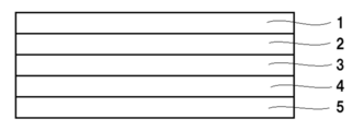
- FIG. 1 is an example of a transparent conductive film, in which 1 is a transparent conductive layer, 2 is a refractive index adjusting layer, 3 is a curable resin layer, 4 is a flat molded body, and 5 is a protective film. Shown.
- the material of the transparent conductive layer is not particularly limited as long as it has conductivity, but ATO (antimony-doped indium oxide), FTO (fluorinated tin oxide), AZO (aluminum-doped zinc oxide), GZO (gallium-doped zinc oxide), ITO (Indium tin composite oxide), Ag, Cu, Au and one or more of carbon nanotubes are preferably contained.
- the thickness of the transparent conductive layer is preferably 1 to 30 nm.
- the transparent conductive layer is used, for example, as a transparent electrode layer.
- the refractive index adjusting layer is a layer for adjusting the refractive index, and can make it difficult to see the pattern after etching.
- the refractive index adjusting layer may be a layer having a refractive index close to the refractive index of the transparent conductive layer (high refractive index layer), or may be composed of both a high refractive index layer and a low refractive index layer. ..
- a configuration in which the high refractive index layer and the low refractive index layer are formed from the side closer to the transparent conductive layer is preferable. Details of the high-refractive-index layer and the low-refractive-index layer can be referred to in paragraphs 0071 to 0095 of JP-A-2019-124913, the contents of which are incorporated in the present specification.
- the curable resin layer can impart hardness, chemical resistance, scratch resistance, etc. to the multilayer body.
- a thermosetting resin or an energy ray curable resin having a pencil hardness of H or more can be used as the curable resin layer.
- the energy ray-curable resin include ultraviolet curable resins. Specific examples thereof include acrylic type, polyester type, urethane type, silicone type, amide type, epoxy type and the like, and include ultraviolet curable monomers, oligomers, polymers and the like.
- the thickness of the curable resin layer is not particularly limited, but is preferably 0.5 to 10 ⁇ m.
- a resin film is preferable.
- the resin constituting the resin film include polypropylene, polyethylene, polyethylene terephthalate, polycarbonate, cycloolefin, polyarylate, polysulfone, polyamide, and polyimide.
- the thickness of the protective film is not particularly limited, but is preferably 10 to 100 ⁇ m.
- the transparent conductive film is not limited to the configuration shown in FIG.
- a curable resin layer may be further provided between the flat plate-shaped molded product and the protective film.
- an adhesive layer, an adhesive layer, or the like may be provided between the constituent layers shown in FIG. In particular, it is preferable to have an adhesive layer on the surface of the protective film.
- the transparent conductive film of FIG. 1 further includes a hard coat layer, an antiglare layer, an antireflection layer, a low reflection layer, a conductive layer, an antiblocking layer, an antistatic layer, a colored layer, an ultraviolet absorbing layer, an antifouling layer and the like. It may have the functional layer of.
- the hard coat layer the description in paragraphs 096 to 0102 of JP-A-2019-124913 can be referred to, and the content thereof is incorporated in the present specification.
- the transparent conductive film is preferably used in a touch panel film sensor, electronic paper, a dye-sensitized solar cell, a touch sensor, and the like. In particular, it is preferably used in applications that require bending resistance, such as folding displays and curved displays.
- the flat molded body and the multilayer body of the present invention include electrical and electronic equipment, OA equipment, information terminal equipment, mechanical parts, home appliances, vehicle parts, building materials, various containers, leisure goods / miscellaneous goods, and lighting. It can be used for parts such as equipment, parts for various household electric appliances, housings for electric appliances, containers, covers, storage parts, cases, covers and cases for lighting equipment, and the like.
- electrical and electronic equipment include personal computers, game machines, television receivers, display devices such as liquid crystal display devices and plasma display devices, printers, copiers, scanners, fax machines, electronic notebooks and PDAs, electronic desk computers, and the like.
- Examples thereof include electronic dictionaries, cameras, video cameras, mobile phones, smartphones, tablets, battery packs, recording medium drives and readers, mice, ten keys, CD players, MD players, portable radio / audio players, and the like. Further, it can be preferably used in the fields of illuminated signboards, liquid crystal backlights, lighting displays, traffic signs, signboards, screens, automobile parts such as reflectors and meter parts, toys, and decorative items.
- B1 Aromatic polycarbonate obtained by an interfacial polymerization method using bisphenol A as a starting material (manufactured by Mitsubishi Engineering Plastics, H-4000F, viscosity average molecular weight 16,000, glass transition temperature 143 ° C)
- B2 Aromatic polycarbonate obtained by an interfacial polymerization method using bisphenol A as a starting material (manufactured by Mitsubishi Engineering Plastics, H-7000F, viscosity average molecular weight 14,000, glass transition temperature 141 ° C.)
- B3 Aromatic polycarbonate obtained by an interfacial polymerization method using bisphenol A as a starting material (manufactured by Mitsubishi Engineering Plastics Co., Ltd., E-2000F, viscosity average molecular weight 27,000, glass transition temperature 151 ° C.)
- B4 Aromatic polycarbonate obtained by an interfacial polymerization method using bisphenol A as a starting material (manufactured by Mitsubishi Engineering Plastics,
- C1 3,9-bis ⁇ 2- [3- (3-t-butyl-4-hydroxy-5-methylphenyl) propionyloxy] -1,1-dimethylethyl ⁇ -2,4 8,10-Tetraoxaspiro [5.5]
- Undencan (semi-hindered phenolic antioxidant, manufactured by ADEKA, ADEKA STAB AO-80)
- C2 Bis (2,6-di-tert-butyl-4-methylphenyl) pentaerythritol diphosphite (phosphorus antioxidant, ADEKA, ADEKA STAB PEP-36)
- Example 1 Manufacturing of pellets> Each of the above-mentioned components was weighed so as to have the amount of addition shown in Table 1 or Table 2, respectively. The blending amount of each component shown in Table 1 or Table 2 is shown in parts by mass. Then, after mixing with a tumbler for 15 minutes, melt-kneading was performed at a cylinder temperature of 300 ° C. by a twin-screw extruder with a vent having a screw diameter of 32 mm (“TEX30 ⁇ ” manufactured by Japan Steel Works, Ltd.), and pellets were obtained by strand cutting.
- TEX30 ⁇ manufactured by Japan Steel Works, Ltd.
- a film (flat molded product) was produced by the following method.
- TEX30 ⁇ twin-screw extruder
- the film was extruded in a molten state, pressure-bonded with a first roll and a second roll, and then cooled and solidified to prepare a film (flat plate-shaped molded product).
- the cylinder and T-die temperatures were set to 300 ° C.
- the thickness (unit: ⁇ m) of the finally obtained film (flat molded product) was adjusted by changing the roll speeds of the first roll and the second roll so as to have the values shown in Table 1 or Table 2. I went. Details of the first roll and the second roll used are as follows. -First roll: Silicone rubber roll (IT68S-MCG) manufactured by Mochida Shoko Co., Ltd. Dimensions: Outer diameter 260 mm x width 600 mm Roll temperature: 50 ° C -Second roll: Mirror metal rigid body roll (Surface: Hard chrome treatment) Core metal dimensions: outer diameter 250 mm x width 600 mm Roll temperature: 140 ° C
- the glass transition temperature of the film (flat plate-shaped molded product) obtained above or the raw material polycarbonate was measured as follows.
- the film (flat molded body) was cut with scissors and measured.
- About 10 mg of the above sample was heated and lowered in two cycles according to the following DSC (differential scanning calorimetry) measurement conditions, and the glass transition temperature at the time of raising the temperature in the second cycle was measured.
- the intersection of the straight line extending the baseline on the low temperature side to the high temperature side and the tangent of the turning point is the starting glass transition temperature
- the intersection of the straight line extending the baseline on the high temperature side to the low temperature side and the tangent of the turning point is defined as the starting glass transition temperature.
- the end glass transition temperature was defined, and the intermediate point between the start glass transition temperature and the end glass transition temperature was defined as the glass transition temperature (unit: ° C.) in the present invention.
- Measurement start temperature 30 ° C
- Temperature rise rate 10 ° C / min
- Reaching temperature 250 ° C
- Temperature lowering rate 20 ° C./min
- a differential scanning calorimeter (DSC, manufactured by Hitachi High-Tech Science Corporation, "DSC7020" was used as the measuring device.
- a film flat molded article was produced from the pellets. At that time, if it could be extruded, it was shown as A, and if it could not be extruded because the melt viscosity was too high, it was shown as B.
- the film (flat plate-shaped molded body) obtained above is subjected to a stress load (in the flow direction during film forming) on the film (flat plate-shaped molded body) using an ellipsometer under an environment of 23 ° C. and a relative humidity of 50%.
- the in-plane retardation (Re) value of the film (plate-shaped molded product) was measured at a wavelength of 633 nm while applying 0 to 720 gf). Then, the photoelastic coefficient was calculated from the stress and the slope of Re.
- values of 10 to 12 times are shown in units of m 2 / N.
- the ellipsometer an ellipsometer M-220 manufactured by JASCO Corporation was used.
- ⁇ Measurement of haze> The haze (unit:%) of the film (flat plate-shaped molded product) obtained above was measured using a haze meter under the condition of a D65 light source with a field of view of 10 °.
- HM-150 manufactured by Murakami Color Technology Research Institute was used.
- ⁇ Heat shrinkage rate> Square samples of 150 mm in the width direction and 150 mm in the flow direction were cut out at any three locations in the film (flat plate-shaped molded product) obtained above. Marking points with an interval of about 100 mm in the width direction and the flow direction of the film (flat plate) in an atmosphere of 23 ° C. and a relative humidity of 50% were marked on the sample, and the intervals were measured using a caliper.
- the heat treatment was performed in a constant temperature bath at 160 ° C. for 30 minutes. After taking out from a constant temperature bath and allowing it to stand in an atmosphere of 23 ° C. and 50% relative humidity for 60 minutes, the above-mentioned reference point interval is measured with a caliper in an atmosphere of 23 ° C.
- Heat shrinkage rate (%) [ ⁇ (dimensions before heat treatment)-(dimensions after heat treatment) ⁇ / (dimensions before heat treatment)] x 100
- the flow direction means the extrusion direction, and in the case of casting, it means the flow direction.
- the width direction means a direction perpendicular to the flow direction.
- Example 2 Comparative Examples 1 to 4
- Example 1 As shown in Table 1 or Table 2, the formulation of each component of the flat plate-shaped molded product was changed, and the others were carried out in the same manner.
- Example 5 In Example 1, as shown in Table 1 or Table 2, the formulation of each component of the flat plate-shaped molded product was changed, and further, the following changes were made in the production of the film (flat plate-shaped molded product), and the others were similarly changed. went.
- -Second roll Embossed roll with arithmetic mean roughness of 2.4 ⁇ m Core dimensions: Outer diameter 250 mm x width 600 mm Roll temperature: 140 ° C
- Comparative Example 5 since the embossed roll was used, the haze of the film (flat plate-shaped molded product) was high and it could not be used as an optical film. Therefore, light leakage, bending resistance, and heat shrinkage were not evaluated.
- Comparative Example 6 In Example 1, as shown in Table 1 or Table 2, the formulation of each component of the flat plate-shaped molded product was changed, and the others were carried out in the same manner. In Comparative Example 6, the melt viscosity was too high to be processed into a film.
- Transparent conductive layer 2 Refractive index adjustment layer 3 Curable resin layer 4 Flat plate-shaped molded body 5 Protective film 21 Surface light source 22 Polarizing sheet 23 Cylindrical sample 24 Polarizing sheet
Landscapes
- Chemical & Material Sciences (AREA)
- Health & Medical Sciences (AREA)
- Chemical Kinetics & Catalysis (AREA)
- Medicinal Chemistry (AREA)
- Polymers & Plastics (AREA)
- Organic Chemistry (AREA)
- Engineering & Computer Science (AREA)
- Manufacturing & Machinery (AREA)
- Materials Engineering (AREA)
- Manufacture Of Macromolecular Shaped Articles (AREA)
- Laminated Bodies (AREA)
Priority Applications (2)
| Application Number | Priority Date | Filing Date | Title |
|---|---|---|---|
| CN202080083194.XA CN114746487B (zh) | 2019-12-04 | 2020-12-01 | 平板状成型体和多层体 |
| JP2021562657A JP7687211B2 (ja) | 2019-12-04 | 2020-12-01 | 平板状成形体および多層体 |
Applications Claiming Priority (2)
| Application Number | Priority Date | Filing Date | Title |
|---|---|---|---|
| JP2019-219351 | 2019-12-04 | ||
| JP2019219351 | 2019-12-04 |
Publications (1)
| Publication Number | Publication Date |
|---|---|
| WO2021112082A1 true WO2021112082A1 (ja) | 2021-06-10 |
Family
ID=76221603
Family Applications (1)
| Application Number | Title | Priority Date | Filing Date |
|---|---|---|---|
| PCT/JP2020/044671 Ceased WO2021112082A1 (ja) | 2019-12-04 | 2020-12-01 | 平板状成形体および多層体 |
Country Status (3)
| Country | Link |
|---|---|
| JP (1) | JP7687211B2 (https=) |
| CN (1) | CN114746487B (https=) |
| WO (1) | WO2021112082A1 (https=) |
Citations (6)
| Publication number | Priority date | Publication date | Assignee | Title |
|---|---|---|---|---|
| JPS608356A (ja) * | 1983-06-27 | 1985-01-17 | Sumitomo Chem Co Ltd | 樹脂組成物 |
| JPS63277232A (ja) * | 1987-02-06 | 1988-11-15 | Daicel Chem Ind Ltd | 芳香族ポリカ−ボネ−ト三元共重合体 |
| JPH05179096A (ja) * | 1991-12-27 | 1993-07-20 | Sumitomo Dow Ltd | 芳香族ポリカーボネート樹脂組成物 |
| JPH10310692A (ja) * | 1997-05-13 | 1998-11-24 | Mitsubishi Chem Corp | 芳香族ポリカーボネート樹脂組成物およびそれからなる光学製品部材 |
| JP2001249222A (ja) * | 2000-03-02 | 2001-09-14 | Teijin Ltd | 反射防止フィルム及びそれを用いてなる発光表示素子 |
| JP2012041445A (ja) * | 2010-08-19 | 2012-03-01 | Teijin Chem Ltd | 光学レンズ用ポリカーボネート共重合体およびそれを用いた光学レンズ |
Family Cites Families (2)
| Publication number | Priority date | Publication date | Assignee | Title |
|---|---|---|---|---|
| JPH06200005A (ja) * | 1992-11-02 | 1994-07-19 | Teijin Chem Ltd | 芳香族ポリカーボネート共重合体 |
| JPWO2006028131A1 (ja) * | 2004-09-10 | 2008-05-08 | グンゼ株式会社 | タッチパネル及びタッチパネル用フィルム材料の製造方法 |
-
2020
- 2020-12-01 WO PCT/JP2020/044671 patent/WO2021112082A1/ja not_active Ceased
- 2020-12-01 JP JP2021562657A patent/JP7687211B2/ja active Active
- 2020-12-01 CN CN202080083194.XA patent/CN114746487B/zh active Active
Patent Citations (6)
| Publication number | Priority date | Publication date | Assignee | Title |
|---|---|---|---|---|
| JPS608356A (ja) * | 1983-06-27 | 1985-01-17 | Sumitomo Chem Co Ltd | 樹脂組成物 |
| JPS63277232A (ja) * | 1987-02-06 | 1988-11-15 | Daicel Chem Ind Ltd | 芳香族ポリカ−ボネ−ト三元共重合体 |
| JPH05179096A (ja) * | 1991-12-27 | 1993-07-20 | Sumitomo Dow Ltd | 芳香族ポリカーボネート樹脂組成物 |
| JPH10310692A (ja) * | 1997-05-13 | 1998-11-24 | Mitsubishi Chem Corp | 芳香族ポリカーボネート樹脂組成物およびそれからなる光学製品部材 |
| JP2001249222A (ja) * | 2000-03-02 | 2001-09-14 | Teijin Ltd | 反射防止フィルム及びそれを用いてなる発光表示素子 |
| JP2012041445A (ja) * | 2010-08-19 | 2012-03-01 | Teijin Chem Ltd | 光学レンズ用ポリカーボネート共重合体およびそれを用いた光学レンズ |
Also Published As
| Publication number | Publication date |
|---|---|
| CN114746487B (zh) | 2025-11-28 |
| JP7687211B2 (ja) | 2025-06-03 |
| JPWO2021112082A1 (https=) | 2021-06-10 |
| CN114746487A (zh) | 2022-07-12 |
Similar Documents
| Publication | Publication Date | Title |
|---|---|---|
| TWI781090B (zh) | 光學積層體及使用該光學積層體之影像顯示裝置 | |
| US9581747B2 (en) | Method for producing optical film, optical film, laminated polarizing plate, and image display | |
| JP6500097B2 (ja) | 透明プラスチックシート | |
| WO2016185722A1 (ja) | 樹脂組成物およびフィルム | |
| KR102313558B1 (ko) | 압출 수지판의 제조 방법 및 압출 수지판 | |
| KR20170125098A (ko) | 터치 패널을 갖는 액정 표시 장치 및 그 제조 방법 | |
| JP2022080270A (ja) | 樹脂組成物、平板状成形体、多層体、成形品および成形品の製造方法 | |
| CN109562553B (zh) | 挤出树脂板的制造方法和挤出树脂板 | |
| TW202033370A (zh) | 附相位差層之偏光板 | |
| CN113423757A (zh) | 聚碳酸酯系树脂组合物或共聚物、及光学膜 | |
| JP7687211B2 (ja) | 平板状成形体および多層体 | |
| WO2022131014A1 (ja) | 樹脂組成物、平板状成形体、多層体、成形品および成形品の製造方法 | |
| WO2017135239A1 (ja) | 光学積層体および該光学積層体を用いた画像表示装置 | |
| WO2020241671A1 (ja) | フィルムおよびフィルムの製造方法 | |
| TW202244121A (zh) | 相位差膜、使用該相位差膜之圓偏光板及圖像顯示裝置 | |
| JP6795128B1 (ja) | 組成物、フィルム、およびフィルムの製造方法 | |
| US11446899B2 (en) | Transparent film and transparent electrode | |
| CN114507432B (zh) | 膜、多层体和透明导电性膜 | |
| JPWO2016002665A1 (ja) | 光学フィルム及びその製造方法 | |
| JP6825755B1 (ja) | 組成物、フィルムおよびフィルムの製造方法 | |
| JP7319052B2 (ja) | 透明導電性フィルム用基材および透明導電性フィルム | |
| CN116410582A (zh) | 树脂组合物、膜、多层体和透明导电性膜 | |
| JP7150628B2 (ja) | 透明導電性フィルム積層体 | |
| JP2018024136A (ja) | 透明導電性積層体 | |
| TW202125063A (zh) | 相位差膜及其製造方法、以及使用該相位差膜之圓偏光板及圖像顯示裝置 |
Legal Events
| Date | Code | Title | Description |
|---|---|---|---|
| 121 | Ep: the epo has been informed by wipo that ep was designated in this application |
Ref document number: 20895075 Country of ref document: EP Kind code of ref document: A1 |
|
| ENP | Entry into the national phase |
Ref document number: 2021562657 Country of ref document: JP Kind code of ref document: A |
|
| NENP | Non-entry into the national phase |
Ref country code: DE |
|
| 122 | Ep: pct application non-entry in european phase |
Ref document number: 20895075 Country of ref document: EP Kind code of ref document: A1 |