WO2021112079A1 - 蛍光x線分析装置 - Google Patents
蛍光x線分析装置 Download PDFInfo
- Publication number
- WO2021112079A1 WO2021112079A1 PCT/JP2020/044667 JP2020044667W WO2021112079A1 WO 2021112079 A1 WO2021112079 A1 WO 2021112079A1 JP 2020044667 W JP2020044667 W JP 2020044667W WO 2021112079 A1 WO2021112079 A1 WO 2021112079A1
- Authority
- WO
- WIPO (PCT)
- Prior art keywords
- ray
- fluorescent
- rays
- liquid sample
- axis
- Prior art date
Links
Images


Classifications
-
- G—PHYSICS
- G01—MEASURING; TESTING
- G01N—INVESTIGATING OR ANALYSING MATERIALS BY DETERMINING THEIR CHEMICAL OR PHYSICAL PROPERTIES
- G01N23/00—Investigating or analysing materials by the use of wave or particle radiation, e.g. X-rays or neutrons, not covered by groups G01N3/00 – G01N17/00, G01N21/00 or G01N22/00
- G01N23/22—Investigating or analysing materials by the use of wave or particle radiation, e.g. X-rays or neutrons, not covered by groups G01N3/00 – G01N17/00, G01N21/00 or G01N22/00 by measuring secondary emission from the material
- G01N23/223—Investigating or analysing materials by the use of wave or particle radiation, e.g. X-rays or neutrons, not covered by groups G01N3/00 – G01N17/00, G01N21/00 or G01N22/00 by measuring secondary emission from the material by irradiating the sample with X-rays or gamma-rays and by measuring X-ray fluorescence
Definitions
- the present invention relates to a fluorescent X-ray analyzer capable of measuring the concentration of an element contained in a liquid sample.
- the silicon concentration in phosphoric acid has been measured by, for example, the ion-selective electrode method (see Patent Document 1).
- the ion-selective electrode method see Patent Document 1.
- this measurement method since it is necessary to cool the phosphoric acid to a predetermined temperature, it is difficult to measure the silicon concentration in the phosphoric acid circulating at a high temperature in the etching control device in-line.
- this measurement method since this measurement method has a problem that running is high, a measurement method that is easier to use is required.
- the present invention has been made in view of the above-mentioned problems, and the influence of scattered X-rays is less likely to appear on the output of the detector, and fluorescence X generated by exciting a light element such as silicon (Si) is generated. It is an object of the present invention to provide a fluorescent X-ray analyzer capable of lowering the lower limit of detection of a line and accurately measuring its concentration.
- the fluorescent X-ray analyzer is a fluorescent X-ray analyzer that analyzes a liquid sample containing a first element to be measured and a second element having a larger atomic number than the first element.
- the X-ray source that emits the first X-ray and the second X-ray that is excited by the first X-ray to generate the second X-ray are provided so that the second X-ray is incident on the liquid sample.
- the concentration of the first element in the liquid sample is calculated based on the next target, a detector that detects fluorescent X-rays generated in the liquid sample excited by the second X-ray, and the output of the detector.
- the irradiation center which is the intersection of the second X-ray irradiation optical axis with respect to the sample surface of the liquid sample, and the visual field center, which is the intersection of the detection optical axis of the detector with respect to the sample surface.
- it is characterized in that it is configured to be separated in the sample plane.
- the detector since the detector has the field of view centered at a portion deviated from the irradiation center on the sample surface, the intensity of the scattered X-rays of the second X-ray generated at the irradiation center is large. The component in the scattering direction can be made difficult to enter the field of view of the detector.
- the fluorescent X-rays generated at the irradiation center are uniformly emitted in all directions, the amount of fluorescent X-rays incident in the field of view of the detector is scattered X-rays even if the irradiation center and the field center are shifted. Does not decrease compared to.
- an X-ray permeable film that comes into contact with the liquid sample and forms a sample surface is further provided, and the second X-ray passes through the X-ray permeable film. Anything may be used as long as it is configured to irradiate the liquid sample.
- the X-ray tube, the secondary target, and the detector and the measurement system can be arranged under the liquid sample to perform fluorescent X-ray analysis. Even if the liquid sample evaporates, the vapor does not affect the measurement system. Therefore, the configuration is particularly suitable when the liquid sample has a risk of deterioration of the measurement system due to vapor such as phosphoric acid.
- the measurement system when the measurement system is arranged above the liquid sample and a film or the like is provided to prevent the steam of the liquid sample, bubbles are generated between the liquid sample and the film, which hinders fluorescent X-ray analysis. There is a possibility that extra scattering may occur, but if the liquid sample is analyzed from below via the X-ray transmission film, such a problem can be prevented from occurring in the first place.
- the line-transmitting membrane may be formed of polyimide, aromatic polyetherketone, polyphenylene sulfide, aramid, graphene, or diamond dry carbon.
- the scattered X-rays of the second X-ray generated in the liquid sample are less likely to be incident on the detector, and each device is densely packed, and the optical path length of the fluorescent X-rays generated in the liquid sample to reach the detector.
- the irradiation optical axis of the first X-ray is orthogonal to the Z-axis and the Z-axis at the light source point of the X-ray source.
- the secondary target is the said. It is sufficient that the target surface on which the first X-ray is incident is provided, and the target surface is inclined with respect to the XZ plane and also with respect to the YZ plane.
- Examples thereof include those whose surfaces are inclined with respect to the XZ plane and the YZ plane.
- the detector includes a detection surface for detecting fluorescent X-rays, and the detection surface is an XZ plane. It suffices that the detection surface faces the X-ray source side while being inclined with respect to the X-ray source.
- the secondary targets are required to generate second X-rays separately. It may consist of a plurality of target elements arranged in.
- two target elements are used. , Those arranged so as to sandwich the detector.
- the fluorescence analyzer of the present invention can reduce the running cost as compared with the ion-selective electrode method. Moreover, the concentration of silicon (Si) can be accurately measured. In addition, the concentration of silicon (Si) can be measured in-line.
- the distance between the irradiation center and the visual field center is 3 mm or more and 10 mm or less.
- the fluorescent X-ray analyzer of the present invention since the irradiation center and the detection center are displaced on the sample surface, the intensity of the scattered X-rays generated on the sample surface is high.
- the direction in which the high component is contained makes it easy to deviate from the solid angle that can be detected by the detector, and the intensity of the fluorescent X-ray to be measured can be relatively increased. Therefore, since the background value at the output of the detector can be lowered, the lower limit of detection of fluorescent X-rays can also be lowered. Therefore, even fluorescent X-rays of light elements such as silicon (Si) can be sufficiently detected, and quantitative analysis can be performed.
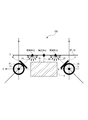
- FIG. 6 is a schematic view of the fluorescent X-ray analyzer according to the same embodiment when viewed along the Z-axis direction.
- FIG. 6 is a schematic view of the fluorescent X-ray analyzer according to the same embodiment when viewed along the Y-axis direction. Schematic graph showing the peaks and absorption edges of fluorescent X-rays of phosphorus (P) and silicon (Si).
- P phosphorus
- Si silicon
- the fluorescent X-ray analyzer 100 measures, for example, the concentration of silicon (Si), which is an element contained in a high-temperature phosphoric acid solution used for wet etching of a nitride film in a semiconductor manufacturing process.
- Si silicon
- phosphoric acid is in a high temperature state of 100 ° C. to 300 ° C., and in this embodiment, it is a liquid sample LS having a temperature of about 160 ° C. or 160 ° C.
- silicon (Si) contained in phosphoric acid is a trace element present at a concentration of about 1/1000 to 1/10000 with respect to phosphorus (P).
- the fluorescent X-ray analyzer 100 of the present embodiment performs fluorescent X-ray analysis on a liquid sample containing a large amount of the second element having an atomic number larger than that of the first element by one.
- a part of phosphoric acid circulating in the etching apparatus is sampled, and fluorescent X-ray analysis is performed in a liquid state without cooling to obtain a silicon (Si) concentration. Is used to measure.
- the fluorescent X-ray analyzer 100 only silicon (Si) is excited to derive fluorescent X-rays, and fluorescent X-rays are not excited from phosphorus (P), or silicon (Si) and phosphorus (P) are excited. ) Are both excited, but the amount of fluorescent X-rays generated from phosphorus (P) is small enough to have little effect on calculating the concentration of silicon (Si).
- the fluorescent X-ray analyzer 100 is in contact with the X-ray source 1, the primary collimator 2, the secondary target 3, the secondary collimator 4, and the liquid sample LS. It is provided with at least a permeable film 5, a detector 6, and a concentration calculator.
- the Cartesian coordinates of the right-handed system are set with the Z-axis as the emission direction of the first X-ray emitted from the X-ray source 1 and the light source point of the X-ray source 1 as a reference, and are used in the description.
- the axis that is perpendicular to the Z-axis through the light source point and forms a surface parallel to the sample surface SP of the liquid sample LS formed by the X-ray transmission film 5 is the X-axis, and the X-axis passes through the light source point.
- the axis orthogonal to the Z axis and the Z axis is set as the Y axis.
- the sample plane SP and the XZ plane are horizontal planes, and the Y axis coincides with the vertical direction.
- the X-ray source 1 emits the first X-ray, and emits X-rays having an energy different from the energy irradiated to the liquid sample LS.
- the fluorescent X-ray generated by irradiating the secondary target 3 with the first X-ray is used as the second X-ray to irradiate the liquid sample LS.
- the X-ray source 1 is, for example, a vacuum vessel 11 in which the inside is kept in a vacuum and a beryllium (Be) window is formed as an X-ray transmission window 12, and an electron beam source (not shown) provided in the vacuum vessel 11.
- a primary target 13 in which electrons emitted from an electron beam source are incident and a first X-ray is generated.
- the primary collimeter 2 limits the range of irradiation of the first X-ray to a predetermined range. That is, the primary collimator 2 limits the first X-ray emitted from the beryllium window into a cylinder having a predetermined radius extending along the Z axis.
- the main energy of the second X-ray emitted from the secondary target 3 excites silicon (Si), which is the first element contained in the liquid sample LS, to generate the corresponding fluorescent X-ray, and the liquid.
- the second element phosphorus (P) contained in the sample LS is selected so as not to be excited and to generate fluorescent X-rays. That is, the energy of the absorption edge of silicon (Si), which is the first element, is E1, the energy of the absorption edge of phosphorus (P), which is the second element, is E2, and the energy of the second X-ray generated by the first X-ray on the target surface 31.
- the energy peak is EP
- the secondary target 3 is configured so as to satisfy E1 ⁇ EP ⁇ E2.
- the secondary target 3 is formed of phosphorus (P) which is not a measurement target.
- the energy EP of the K ⁇ ray which is a fluorescent X-ray generated by the incident of the first X-ray on phosphorus (P)
- the energy E2 at the absorption edge of phosphorus (P) is smaller than the energy E2 at the absorption edge of phosphorus (P).
- the secondary collimator 4 limits the irradiation range and irradiation direction of the second X-ray generated by the secondary target 3 with respect to the sample surface SP. That is, the secondary collimator 4 defines the irradiation optical axis LA of the second X-ray in a predetermined direction.
- the X-ray transmission film 5 is a film extending along a horizontal plane, and forms a sample surface SP in contact with the liquid sample LS on the upper surface thereof.
- the X-ray transmission film 5 is, for example, a resin film having a film thickness of ⁇ m, and is configured to suppress the attenuation of incident second X-rays and fluorescent X-rays generated in the liquid sample LS as much as possible.
- the X-ray transmission film 5 is formed of polyimide or aromatic polyetherketone.
- the second X-ray generated by the secondary target 3 penetrates through the X-ray transmission film 5 and penetrates into the liquid sample LS to a predetermined depth.
- the predetermined depth is about several tens of ⁇ m to several hundreds of ⁇ m.
- the second X-ray incident on the liquid sample LS generates fluorescent X-rays for silicon (Si) contained in the liquid sample LS and also generates scattered X-rays at the same time.
- the X-ray permeable membrane 5 may be formed of polyphenylene sulfide, aramid, graphene, or diamond-like carbon.
- the detector 6 detects fluorescent X-rays generated in the liquid sample LS, and the detection surface 61 is arranged so as to be parallel to the sample surface SP. That is, the detection optical axis DA of the detector 6 is provided so as to be perpendicular to the sample surface SP, and as shown in FIGS. 3 and 4, the detection center which is the intersection of the sample surface SP and the detection optical axis DA. Is placed directly above the detector 6. Further, the detector 6 is arranged so that the area directly below the irradiation center is the outer peripheral portion of the detection surface 61.
- the irradiation center which is the intersection of the irradiation optical axis LA of the second X-ray generated by the secondary target 3 and the sample surface SP, and the detection center are a predetermined distance on the sample surface SP. It is configured to shift.
- the irradiation center is separated from the detection center by a predetermined distance with respect to the X-axis direction according to the tilting direction of the target surface 31 of the secondary target 3, and the separation distance is, for example, 3 mm or more and 10 mm. It is set as follows. In particular, as shown in FIG.
- the detection optical axis LA of the second X-ray and the detection optical axis DA of the detector 6 are arranged so as to be offset, the detection is detected by the detector 6 for the following reasons.
- the ratio of fluorescent X-rays to X-rays can be increased.
- the scattered X-rays generated at the irradiation center are dependent on the scattering angle, and a high-intensity component is generated centering on the direction perpendicular to the sample surface SP (Y-axis direction).
- the detection center is separated from the irradiation center, and the area directly below the irradiation center is located on the outer edge of the detection surface 61.
- the intensity of the scattered X-rays in the solid angle of the field of view of the detector 6 It is possible to prevent the high directional component from being included so that the component with a weak scattering angle and a shallow scattering angle is mainly detected.
- fluorescent X-rays are not angle-dependent and are emitted uniformly in all directions. Therefore, even if the irradiation center and the detection center are deviated, the fluorescent X-rays incident on the solid angle of the field of view of the detector 6 The amount does not decrease as much as the scattered X-rays mentioned above.
- the background value due to the influence of scattered X-rays on the sample surface SP of the second X-ray can be reduced in the output of the detector 6, and the lower limit of detection of fluorescent X-rays mainly of silicon (Si) can be lowered. ..
- the function of the concentration calculator 7 is realized by, for example, a CPU, a memory, an A / D converter, a D / A converter, and a so-called computer having various input / output means.
- the program stored in the memory is executed by the CPU, and various devices cooperate to determine the concentration of silicon (Si) contained in the liquid sample LS based on the output of the detector 6. calculate.
- a specific calculation formula for example, a known one is used.
- silicon which is a trace element contained in the liquid sample LS in the liquid state without cooling or evaporating the liquid sample LS.
- the (Si) concentration can be measured based on fluorescent X-rays.
- the irradiation center of the second X-ray on the sample surface SP and the detection center of the detector 6 are separated from each other, the directional component having high intensity among the scattered X-rays generated on the sample surface SP Is difficult to detect by the detection surface 61, and the ratio of fluorescent X-rays of silicon (Si) to the X-rays detected by the detector 6 can be increased. As a result, the lower limit of detection of silicon (Si) can be lowered as compared with the conventional case.
- the energy of the second X-ray generated by the secondary target 3 is a large amount of phosphorus (P) fluorescence contained in the liquid sample LS.
- P phosphorus
- the secondary target 3, the liquid sample LS, and the detector 6 are densely arranged.
- the optical path length of each X-ray is shortened to prevent attenuation.
- the X-ray transmission film 5 is also set to have a thin film thickness, it is possible to reduce the attenuation when X-rays pass through the X-ray transmission film 5. Therefore, fluorescent X-rays can be detected with the intensity required to measure the concentration of silicon (Si) contained in the liquid sample LS, which is a trace amount of a light element.
- the fluorescent X-ray analyzer according to the present invention is not limited to measuring the concentration of silicon (Si) contained in the phosphoric acid solution. It can be used to measure the concentration of the first element based on fluorescent X-rays with respect to a liquid sample containing the first element to be measured and the second element having an atomic number larger than that of the first element.
- the difference between the atomic numbers of the first element and the second element was 1, but the difference between the atomic numbers of the first element and the second element may be 2, and the difference between the atomic numbers is larger than 2. Is also good.
- a part of the liquid sample is sampled and the fluorescent X-ray analysis is performed as it is without cooling or evaporating.
- the fluorescent X-ray analysis is performed while the liquid sample is flowing.
- Real-time in-line density measurement may be realized.
- a branch flow path formed of an X-ray permeable film is formed in a part of a pipe through which a liquid sample flows, and fluorescent X-ray analysis is performed in that part, or a window made of an X-ray permeable film is formed in a part of the pipe. May be formed and fluorescent X-ray analysis may be performed through the window.
- each device constituting the fluorescent X-ray analyzer is not limited to the one shown in the above embodiment.
- the detection optical axis of the detector may be configured to be obliquely incident on the sample surface instead of being vertically incident on the sample surface.
- the detection surface of the detector may be tilted toward the X-ray source side where the first X-ray is emitted. In this way, the irradiation center and the detection center can be further shifted to make it difficult for the detector to detect the scattered X-rays generated on the detection surface of the liquid sample, and the proportion of the detected fluorescent X-rays can be increased.
- the direction in which the detector is tilted may be appropriately different depending on the type of the liquid sample and the equipment used.
- the detector may be tilted so that the detection surface faces the side opposite to the X-ray source.
- the target surface of the secondary target is not limited to the one that is inclined with respect to both the XZ plane and the YZ plane as in the above embodiment, but only with respect to either the XZ plane or the YZ plane. It may be inclined.
- the secondary target 3 may be composed of a plurality of target elements 3E, and the second X-ray generated by each target element 3E may be separately irradiated to the sample surface SP.
- the target element 3E may be arranged in a substantially V shape so as to sandwich the detector 6 in a mirror plane symmetry with respect to the detection optical axis DA.
- the fluorescent X-rays generated by the first element from the sample surface SP are incident on the detector 6 symmetrically with respect to the detection optical axis DA.
- the measurement time can be shortened by about half, or the statistical measurement error can be reduced and more accurate measurement results can be obtained in the same measurement time.
- the element constituting the secondary target is not limited to phosphorus (P), but may be zirconium (Zr) as shown in FIG. If it is L ⁇ ray which is a component of fluorescent X-ray of zirconium, the above-mentioned relationship between energies is satisfied and the same effect can be obtained. Further, the secondary target may be one formed of yttrium (Y). Further, any element can be used as the secondary target as long as it is an element that generates a second X-ray satisfying E1 ⁇ EP ⁇ E2.
- a fluorescent X-ray analyzer may be used in which the elements constituting the secondary target are selected so as to satisfy E1 ⁇ EP ⁇ E2 in a state where the irradiation center and the detection center are aligned on the sample surface without shifting.
- fluorescent X-rays of both the first element and the second element may be generated with the irradiation center and the detection center shifted by a predetermined distance.
- the material constituting the secondary target described in the embodiment may be used as a material for generating primary X-rays, and the sample may be directly irradiated with primary X-rays.
- a fluorescent X-ray analyzer capable of sufficiently detecting fluorescent X-rays of a light element such as silicon (Si) and performing quantitative analysis.
Abstract
検出器の出力に散乱X線の影響が表れにくくし、例えばシリコン(Si)のような軽元素から発生する蛍光X線の検出下限を下げ、その濃度を正確に測定することができる蛍光X線分析装置を提供するために、測定対象となる第1元素と、前記第1元素よりも原子番号の大きい第2元素と、を含んだ液体試料(LS)を分析する蛍光X線分析装置(100)であって、第1X線を射出するX線源(1)と、前記第1X線によって励起され第2X線が発生し、当該第2X線が前記液体試料(LS)に入射するように設けられた二次ターゲット(3)と、前記液体試料LSに入射した第2X線によって発生する蛍光X線を検出する検出器(6)と、前記検出器6の出力に基づいて、前記第1元素の前記液体試料LS中における濃度を算出する濃度算出器(7)と、を備え、前記液体試料(LS)の試料面(SP)に対する前記第2X線の照射光軸(LA)の交点である照射中心と、前記試料面(SP)に対する前記検出器(6)の検出光軸(DA)の交点である視野中心とが、前記試料面(SP)内において離間するように構成した。
Description
本発明は、液体試料中に含まれる元素の濃度を測定可能な蛍光X線分析装置に関するものである。
半導体製造プロセスにおける窒化膜のウェットエッチングでは、リン酸中のシリコン濃度がエッチングレートに影響を与えることが知られている。このため、リン酸中のシリコン濃度を測定し、リン酸の品質管理が行われる。
従来、リン酸中のシリコン濃度は例えばイオン選択電極法により測定されている(特許文献1参照)。この方法では、リン酸を所定温度まで冷却する必要があるため、エッチング制御装置内において高温で循環しているリン酸中のシリコン濃度をインラインで測定することは難しい。また、この測定方法ではランニングが高いという問題もあるため、より使いやすい測定方法が求められている。
ところで、リン酸中のシリコン濃度を測定するために蛍光X線分析を用いることはこれまで工業的には試みられていない。
これは、シリコン(Si)のような軽元素が励起されて発生する蛍光X線の強度は重元素と比べて低く、加えてエネルギーが低いことで大気による減衰の程度も大きいため、検出器の出力には蛍光X線と同時に発生する散乱X線によるバッググラウンド影響が大きく出てしまい、シリコンを定量分析することが難しいからである。また、分光結晶を用いた蛍光X線分析では、高温のリン酸によって分光結晶を駆動する駆動部及び分光結晶自体が温度影響を受けるため、正確な濃度測定を行うことは難しい。加えて、フィルタによって測定対象としたい蛍光X線のエネルギーを選択しようとすると、検出される強度は低下してしまうので、シリコン(Si)のような軽元素の蛍光X線分析装置には向いていない。
本発明は上述したような問題に鑑みてなされたものであり、検出器の出力に散乱X線の影響が表れにくくし、例えばシリコン(Si)のような軽元が励起されて発生する蛍光X線の検出下限を下げられるようにし、その濃度を正確に測定することができる蛍光X線分析装置を提供することを目的とする。
すなわち、本発明に係る蛍光X線分析装置は、測定対象となる第1元素と、前記第1元素よりも原子番号の大きい第2元素と、を含んだ液体試料を分析する蛍光X線分析装置であって、第1X線を射出するX線源と、前記第1X線によって励起されて第2X線が発生するものであり、当該第2X線が前記液体試料に入射するように設けられた二次ターゲットと、前記第2X線によって励起された前記液体試料において発生する蛍光X線を検出する検出器と、前記検出器の出力に基づいて、前記第1元素の前記液体試料中における濃度を算出する濃度算出器と、を備え、前記液体試料の試料面に対する前記第2X線の照射光軸の交点である照射中心と、前記試料面に対する前記検出器の検出光軸の交点である視野中心とが、前記試料面内において離間するように構成されていることを特徴とする。
このようなものであれば、前記検出器は前記試料面において前記照射中心からずれた箇所を前記視野中心としているので、前記照射中心において発生する前記第2X線の散乱X線のうち強度の大きい散乱方向の成分については前記検出器の視野内に入射しにくくできる。一方、前記照射中心において発生する蛍光X線は全方向に均一射出されるので、前記照射中心と前記視野中心をずらしても蛍光X線が前記検出器の視野内に入射する量は散乱X線と比べて低下しない。したがって、前記検出器の出力に対する散乱X線によるバックグラウンドへの影響を小さくし、蛍光X線の検出下限を下げられる。これらのことから、例えばシリコン(Si)のような軽元素から発生する蛍光X線の強度であってもバックグラウンドノイズの中に埋もれてしまわないようにして、その濃度を測定できるようになる。
前記液体試料について蛍光X線分析を行うのに適した構成としては、前記液体試料と接し、試料面を形成するX線透過膜をさらに備え、前記第2X線が前記X線透過膜を通過して前記液体試料に照射されるように構成されたものであればよい。このようなものであれば、前記液体試料の下側に前記X線管、前記二次ターゲット、及び、前記検出器と測定系を配置して蛍光X線分析を行うことが可能となるので、前記液体試料が蒸発してもその蒸気が測定系に対して影響を与えることがない。したがって、前記液体試料がリン酸のように蒸気によって測定系が劣化する恐れが有る場合に特に適した構成となる。また、測定系を液体試料の上側に配置して前記液体試料の蒸気を防ぐためにフィルムなどを設けた場合には、前記液体試料とフィルムとの間に気泡が発生し、蛍光X線分析を阻害する余計な散乱が発生する可能性があるが、前記X線透過膜を介して前記液体試料を下側から分析するようにすれば、そもそもそのような問題が生じないようにできる。
前記液体試料が高温であったとしても前記X線透過膜を用いた蛍光X線分析を行うのに適した薄さを実現しつつ、十分な機械的強度を保てるようにするには、前記X線透過膜が、ポリイミド、芳香族ポリエーテルケトン、ポリフェニレンサルファイド、アラミド、グラフェン、又は、ダイアモンドライクカーボンで形成されたものであればよい。
前記液体試料において発生する前記第2X線の散乱X線は前記検出器に入射しにくくしつつ、各機器を密集させ、前記液体試料で発生する蛍光X線が前記検出器に至るまでの光路長を短くし、より高強度で検出できるようにして、測定下限値を低くするには、前記第1X線の照射光軸をZ軸、Z軸と前記X線源の光源点で直交し、前記試料面と平行なXZ平面を形成する軸をX軸、前記X線源の光源点を通り、X軸及びZ軸と直交とする軸をY軸とした場合に、前記二次ターゲットが、前記第1X線が入射するターゲット面を具備し、前記ターゲット面が、XZ平面に対して傾斜しているとともに、YZ平面に対しても傾斜していればよい。
前記ターゲット面の具体的な構成例としては、前記ターゲット面に対する法線ベクトルが(X,Y,Z)=(-1/2,1/√2,-1/2)となるように前記ターゲット面がXZ平面及びYZ平面に対して傾斜しているものが挙げられる。
前記検出器に入射する散乱X線に対する蛍光X線の割合を高めて、さらに検出下限を下げるには、前記検出器が、蛍光X線を検出する検出面を具備し、前記検出面がXZ平面に対して傾斜するとともに、当該検出面が前記X線源側を向いていればよい。
前記液体試料において複数箇所で蛍光X線を発生させ、前記検出器に入射する蛍光X線の強度を約複数倍にするには、前記二次ターゲットが、それぞれ別々に第2X線が発生するように配置された複数のターゲット要素からなればよい。
前記検出器で検出されるX線について散乱X線の影響を小さく保ちつつ、前記液体試料で発生する蛍光X線の強度を約2倍にできる具体的な構成例としては、2つのターゲット要素が、前記検出器を挟むように配置されたものが挙げられる。
記第1元素がシリコン(Si)であり、前記第2元素がリン(P)であっても、本願発明の蛍光分析装置であれば、イオン選択電極法と比較してランニングコストを下げて、かつ、シリコン(Si)の濃度を正確に測定可能となる。また、シリコン(Si)の濃度もインラインで測定できるようになる。
前記液体材料で発生する蛍光X線を効率的に検出器に取り込むための具体的な構成例としては、前記照射中心と前記視野中心の離間距離が、3mm以上10mm以下であるものが挙げられる。
このように本発明の蛍光X線分析装置によれば、前記試料面上において前記照射中心と前記検出中心とがずれるように構成されているので、前記試料面において発生する散乱X線のうち強度の高い成分が含まれる方向は、前記検出器が検出可能な立体角内からはずれやすくし、測定対象である蛍光X線の強度を相対的に高められる。したがって、前記検出器の出力におけるバックグラウンドの値を下げられるので、蛍光X線の検出下限も下げられる。このため、例えばシリコン(Si)のような軽元素の蛍光X線でも十分に検出でき、定量分析を行うことが可能となる。
100・・・蛍光X線分析装置
1 ・・・X線源
2 ・・・一次コリメータ
3 ・・・二次ターゲット
4 ・・・二次コリメータ
5 ・・・X線透過膜
6 ・・・検出器
7 ・・・濃度算出器
1 ・・・X線源
2 ・・・一次コリメータ
3 ・・・二次ターゲット
4 ・・・二次コリメータ
5 ・・・X線透過膜
6 ・・・検出器
7 ・・・濃度算出器
本発明の一実施形態における蛍光X線分析装置100について図1乃至図5を参照しながら説明する。この蛍光X線分析装置100は、例えば半導体製造プロセスにおいて窒化膜のウェットエッチングに用いられる高温リン酸液中に含まれる元素であるシリコン(Si)の濃度を測定するものである。例えばリン酸は100℃~300℃の高温状態にあり、本実施形態では160℃又は160℃前後の温度の液体試料LSである。加えて、リン酸中に含まれるシリコン(Si)はリン(P)に対して1/1000程度から1/10000程度の濃度で存在する微量元素である。すなわち、液体試料LSであるリン酸において、測定対象となる第1元素はシリコン(Si)であり、シリコン(Si)よりも原子番号の大きい第2元素はリン(P)である。すなわち、本実施形態の蛍光X線分析装置100は、第1元素に対して原子番号が1つだけ大きい第2元素が多量に含まれている液体試料について蛍光X線分析を行う。本実施形態の蛍光X線分析装置100は、例えばエッチング装置内において循環しているリン酸について一部サンプリングし、冷却なしで液体状態のまま蛍光X線分析を行って、シリコン(Si)の濃度を測定するために用いられる。このため、蛍光X線分析装置100は、シリコン(Si)のみが励起されて蛍光X線が派生し、リン(P)からは蛍光X線が励起されない、あるいは、シリコン(Si)及びリン(P)の両方が励起されたとしてもリン(P)から発生する蛍光X線はシリコン(Si)の濃度を算出するのに影響をほとんど与えない程度に少量となるように構成されている。
具体的には図1乃至図4に示すように、この蛍光X線分析装置100は、X線源1と、一次コリメータ2、二次ターゲット3、二次コリメータ4、液体試料LSと接するX線透過膜5、検出器6、濃度算出器を少なくとも備えたものである。以下の説明では、X線源1から射出される第1X線の射出方向をZ軸と、X線源1の光源点を基準として右手系の直交座標を設定し、説明に用いる。すなわち、光源点を通ってZ軸に対して垂直であり、X線透過膜5により形成される液体試料LSの試料面SPと並行な面を形成する軸をX軸、光源点を通ってX軸、Z軸と直交する軸をY軸として設定する。本実施形態では試料面SP及びXZ平面は水平面であり、Y軸は鉛直方向と一致させてある。
X線源1は、第1X線を射出するものであり、液体試料LSに対して照射したエネルギーとは異なるエネルギーのX線を射出する。この第1X線を二次ターゲット3に照射することで発生する蛍光X線を第2X線として液体試料LSに対して照射する。X線源1は例えば内部が真空に保たれるとともに、X線透過窓12としてベリリウム(Be)窓が形成された真空容器11と、真空容器11内に設けられた電子線源(図示しない)と電子線源から射出された電子が入射し第1X線が発生する一次ターゲット13とを備えたものである。
一次コリメータ2は、第1X線の照射される範囲を所定範囲に制限するものである。すなわち、一次コリメータ2は、ベリリウム窓から射出された第1X線をZ軸に沿って延びる所定半径の円筒内に限定する。
二次ターゲット3は、第1X線の入射するターゲット面31を具備するブロック体であり、ターゲット面31に入射した第1X線により発生する第2X線が二次ターゲット3の上方に配置された液体試料LS及びX線透過膜5へと射出されるように構成されている。具体的には図1、図3、図4に示すようにターゲット面31はXZ平面及びYX平面に対して傾斜している。本実施形態ではターゲット面31に対する法線ベクトルが(X,Y,Z)=(-1/2,1/√2,-1/2)となるようにターゲット面31はXZ平面及びYZ平面に対して傾斜している。
また、この二次ターゲット3から射出される第2X線の主となるエネルギーは、液体試料LS中に含まれる第1元素であるシリコン(Si)を励起し対応する蛍光X線を発生させ、液体試料LS中に含まれる第2元素であるリン(P)については励起せず、蛍光X線を発生させないように選択されている。すなわち、第1元素であるシリコン(Si)の吸収端のエネルギーをE1、第2元素であるリン(P)の吸収端のエネルギーをE2、ターゲット面31において第1X線により発生する第2X線のエネルギーピークをEPとした場合に、E1<EP<E2を満たすように二次ターゲット3は構成されている。本実施形態では二次ターゲット3は測定対象ではないリン(P)で形成されている。ここで、図5のグラフに示すようにリン(P)に第1X線が入射して発生する蛍光X線であるKα線のエネルギーEPは、リン(P)の吸収端のエネルギーE2よりも小さく、シリコン(Si)の吸収端のエネルギーE1よりも大きい。つまり、ある元素の吸収端のエネルギーは、第1X線が入射して発生する第2X線のエネルギーよりも大きくなるので、液体試料LS中において除外対象としたい第2元素で二次ターゲット3を形成することで、二次ターゲット3で発生する第2X線によって液体試料LSから第2元素の蛍光X線が射出されないようにできる。
図1乃至図4に示すように二次コリメータ4は、二次ターゲット3で発生する第2X線の試料面SPに対する照射範囲及び照射方向を限定するものである。すなわち、二次コリメータ4によって第2X線の照射光軸LAは所定方向に規定される。
X線透過膜5は水平面に沿って延びる膜であり、その上面において液体試料LSと接して試料面SPを形成する。このX線透過膜5は例えばμm単位の膜厚有した樹脂膜であり、入射する第2X線や液体試料LSにおいて発生する蛍光X線の減衰をできる限り抑えられるように構成されている。本実施形態ではX線透過膜5はポリイミド又は芳香族ポリエーテルケトンで形成されたものである。二次ターゲット3で発生する第2X線は、このX線透過膜5を透過して液体試料LSに対して所定深さまで侵入する。ここで所定深さはおよそ数十μmから数百μmである。液体試料LSに入射した第2X線は前述したように液体試料LSに含まれるシリコン(Si)については蛍光X線を発生させるとともに散乱X線も同時に発生させる。なお、X線透過膜5は、ポリフェニレンサルファイド、アラミド、グラフェン、又は、ダイアモンドライクカーボンのいずれかで形成されたものであってもよい。
検出器6は液体試料LSで発生した蛍光X線を検出するものであり、その検出面61が試料面SPと平行となるように配置されている。すなわち、検出器6の検出光軸DAは試料面SPに対して垂直となるように設けられており、図3及び図4に示すように試料面SPと検出光軸DAの交点である検出中心は検出器6の直上に配置される。また、検出器6は照射中心の直下は検出面61の外周部となるように配置してある。具体的には、各図に示すように二次ターゲット3で発生する第2X線の照射光軸LAと試料面SPとの交点である照射中心と、検出中心とは試料面SP上において所定距離ずれるように構成されている。本実施形態では二次ターゲット3のターゲット面31の傾いている方向に応じて、検出中心に対して照射中心はX軸方向に対して所定距離だけ離れており、その離間距離は例えば3mm以上10mm以下に設定されている。特に図3に示すようにこのように第2X線の照射光軸LAと検出器6の検出光軸DAがずらして配置されているので、以下のような理由により、検出器6で検出されるX線のうち蛍光X線の比率を高められる。この例であれば照射中心において発生する散乱X線は散乱角に対して依存性があり、試料面SPに垂直な方向(Y軸方向)を中心として強度の高い成分が発生する。本実施形態では検出中心が照射中心から離間しているとともに、照射中心の直下は検出面61の外縁に配置されているので、検出器6の視野の立体角中に散乱X線のうちの強度の高い方向成分は入らないようにして、強度の弱い散乱角の浅い成分が主として検出されるようにできる。一方、蛍光X線には角度依存性がなく、全方向に均一に射出されるので、照射中心と検出中心がずれていても、検出器6の視野の立体角内に入射する蛍光X線の量については前述した散乱X線ほどは減少しない。この結果、検出器6の出力には第2X線の試料面SPにおける散乱X線の影響によるバックグラウンドの値を小さくし、主にシリコン(Si)の蛍光X線の検出下限を下げることができる。
濃度算出器7は、例えばCPU、メモリ、A/Dコンバータ、D/Aコンバータ、各種入出力手段を有したいわゆるコンピュータによってその機能が実現されるものである。この濃度算出器7は、メモリに格納されているプログラムがCPUによって実行され、各種機器が協業することによって、検出器6の出力に基づき、液体試料LS中に含まれるシリコン(Si)の濃度を算出する。具体的な算出式は例えば既知のものが用いられる。
このように構成された本実施形態の蛍光X線分析装置100によれば、液体試料LSを冷やしたり蒸発させたりすることなく、液体の状態のままで液体試料LSに含まれる微量元素であるシリコン(Si)濃度を蛍光X線に基づいて測定することができる。
すなわち、本実施形態では試料面SPにおける第2X線の照射中心と、検出器6の検出中心とがそれぞれ離間させてあるので、試料面SPで発生する散乱X線のうち強度の高い方向成分については検出面61により検出されにくくし、検出器6で検出されるX線のうち、シリコン(Si)の蛍光X線の比率を高められる。この結果、シリコン(Si)の検出下限を従来よりも下げることができる。
また、二次ターゲット3の少なくともターゲット面31はリン(P)で形成されているので、二次ターゲット3で発生する第2X線のエネルギーは液体試料LS中に多量に含まれるリン(P)蛍光X線の発生を低減して、液体試料LS中に微量に含まれるシリコン(Si)の蛍光X線だけを発生させられる。このため、多量に存在するリン(P)の蛍光X線のピークにおける裾部分にシリコン(Si)の蛍光X線のピークが隠れてしまうことがない。したがって、シリコン(Si)のような軽元素の強度の低い蛍光X線からシリコン(Si)の濃度正確に測定できる。言い換えると、シリコン(Si)とリン(P)のように原子番号が連続する元素が含まれているとともに、測定対象である第1元素に対して妨害元素となる第2元素が非常に多い液体試料であるために、従来であれば蛍光X線分析でそれぞれを分離して分析することが難しいと考えられ、工業的には測定が試みすらされていなかった微量元素の濃度が本実施形態の蛍光X線分析装置100であれば可能となる。
さらに、二次ターゲット3、液体試料LS、検出器6のそれぞれを密集させて配置している。各X線の光路長を短くし、減衰を生じにくくしている。また、X線透過膜5も膜厚が薄く設定されているので、このX線透過膜5をX線が通過する際の減衰も低減できる。したがって、微量の軽元素である液体試料LSに含まれるシリコン(Si)の濃度を測定するのに必要な強度で蛍光X線を検出できる。
その他の実施形態について説明する。
本発明に係る蛍光X線分析装置は、リン酸液中に含まれるシリコン(Si)の濃度を測定するものに限られない。測定対象となる第1元素と、第1元素よりも原子番号の大きい第2元素を含む液体試料について、第1元素の濃度を蛍光X線に基づいて測定するために用いることができる。第1元素と第2元素の原子番号の差は1であったが、第1元素と第2元素の原子番号の差が2であっても良いし、原子番号の差が2よりも大きくても良い。
前記実施形態では、液体試料の一部をサンプリングして冷却や蒸発させることなく、そのままの状態で蛍光X線分析を行っていたが、例えば液体試料が流れている状態で蛍光X線分析を行い、リアルタイムでのインライン濃度測定を実現してもよい。例えば液体試料の流れている配管の一部にX線透過膜で形成された分岐流路を形成し、その部分で蛍光X線分析を行う、あるいは、配管の一部でX線透過膜による窓を形成し、その窓を介して蛍光X線分析を行うようにしてもよい。
蛍光X線分析装置を構成する各機器の配置や向きは前記実施形態に示した物に限られない。例えば検出器の検出光軸は試料面に対して垂直に入射するのではなく、試料面に対して斜めに入射するように構成してもよい。この場合、図1乃至4に示した配置であれば、検出器の検出面を第1X線が射出されるX線源側へと傾ければよい。このようにして照射中心と検出中心をさらにずらして、液体試料の検出面において発生する散乱X線が検出器で検出されにくくし、検出される蛍光X線の割合を高めることができる。なお、液体試料の種類や使用する機器に応じて検出器を傾ける向きは適宜異ならせてもよく、例えばX線源とは反対側に検出面が向くように検出器を傾けても良い。また、二次ターゲットのターゲット面についても前記実施形態のようにXZ平面、及び、YZ平面の両方に対して傾斜しているものに限られず、XZ平面、又は、YZ平面いずれか一方のみに対して傾斜しているものであってもよい。
また、図6に示すように二次ターゲット3を複数のターゲット要素3Eで構成し、各ターゲット要素3Eで発生する第2X線が試料面SPに対して別々に照射されるようにしてもよい。より具体的には検出器6を挟むようにターゲット要素3Eを概略V字状に検出光軸DAに対して鏡面対称で配置すればよい。このようにすれば、検出器6に対して試料面SPから第1元素が発生する蛍光X線が検出光軸DAに対して対称に入射するようになるので、検出される強度を前記実施形態の約2倍にできる。この結果、測定時間を約半分に短縮したり、同じ測定時間で統計的な測定誤差を低減してより正確な測定結果を得たりすることができる。
二次ターゲットを構成する元素は、リン(P)に限られるものではなく、図5に示すようにジルコニウム(Zr)であってもよい。ジルコニウムの蛍光X線の成分であるLα線であれば上述したエネルギー間の関係を満たし、同様の効果を得られる。また、二次ターゲットはイットリウム(Y)で形成されたものであってもよい。また、E1<EP<E2を満たす第2X線が発生する元素であれば、任意の元素を二次ターゲットに用いることができる。
本発明については測定対象となる第1元素と第2元素との原子番号の関係や濃度の関係によって様々な実施形態が考えられる。例えば試料面上において照射中心と検出中心をずらさずに一致させた状態で二次ターゲットを構成する元素をE1<EP<E2を満たすように選択した蛍光X線分析装置であってもよい。あるいは、照射中心と検出中心を所定距離ずらした状態で第1元素及び第2元素の両方の蛍光X線が発生するようにしてもよい。
また、実施形態において説明した2次ターゲットを構成する材料を、1次X線を発生させるための材料として使用し、1次X線を試料に直接照射しても良い。
その他、本発明の趣旨に反しない限りにおいて各実施形態について様々な変形を行ったり、各実施形態の一部同士を組み合わせたりしても構わない。
本発明であれば、例えばシリコン(Si)のような軽元素の蛍光X線でも十分に検出でき、定量分析を行うことが可能な蛍光X線分析装置を提供できる。
Claims (10)
- 測定対象となる第1元素と、前記第1元素よりも原子番号の大きい第2元素と、を含んだ液体試料を分析する蛍光X線分析装置であって、
第1X線を射出するX線源と、
前記第1X線によって励起されて第2X線が発生するものであり、当該第2X線が前記液体試料に入射するように設けられた二次ターゲットと、
前記第2X線によって励起された前記液体試料において発生する蛍光X線を検出する検出器と、
前記検出器の出力に基づいて、前記第1元素の前記液体試料中における濃度を算出する濃度算出器と、を備え、
前記液体試料の試料面に対する前記第2X線の照射光軸の交点である照射中心と、前記試料面に対する前記検出器の検出光軸の交点である視野中心とが、前記試料面内において離間するように構成されていることを特徴とする蛍光X線分析装置。 - 前記液体試料と接し、試料面を形成するX線透過膜をさらに備え、
前記第2X線が前記X線透過膜を通過して前記液体試料に照射されるように構成された請求項1記載の蛍光X線分析装置。 - 前記X線透過膜が、ポリイミド、芳香族ポリエーテルケトン、ポリフェニレンサルファイド、アラミド、グラフェン、又は、ダイアモンドライクカーボンで形成された請求項2記載の蛍光X線分析装置。
- 前記第1X線の照射光軸をZ軸、Z軸と前記X線源の光源点で直交し、前記試料面と平行なXZ平面を形成する軸をX軸、前記X線源の光源点を通り、X軸及びZ軸と直交とする軸をY軸とした場合に、
前記二次ターゲットが、前記第1X線が入射するターゲット面を具備し、
前記ターゲット面が、XZ平面に対して傾斜しているとともに、YZ平面に対しても傾斜している請求項1乃至3いずれかに記載の蛍光X線分析装置。 - 前記ターゲット面に対する法線ベクトルが(X,Y,Z)=(-1/2,1/√2,-1/2)となるように前記ターゲット面がXZ平面及びYZ平面に対して傾斜している請求項4記載の蛍光X線分析装置。
- 前記検出器が、蛍光X線を検出する検出面を具備し、
前記検出面がXZ平面に対して傾斜するとともに、当該検出面が前記X線源側を向いている請求項4又は5記載の蛍光X線分析装置。 - 前記二次ターゲットが、それぞれ別々に第2X線が発生するように配置された複数のターゲット要素からなる請求項1乃至5いずれかに記載の蛍光X線分析装置。
- 2つの前記ターゲット要素が、前記検出器を挟むように配置された請求項7記載の蛍光X線分析装置。
- 前記第1元素がシリコン(Si)であり、
前記第2元素がリン(P)である請求項1乃至8いずれかに記載の蛍光X線分析装置。 - 前記照射中心と前記視野中心の離間距離が、3mm以上10mm以下である請求項9記載の蛍光X線分析装置。
Priority Applications (1)
| Application Number | Priority Date | Filing Date | Title |
|---|---|---|---|
| JP2021562654A JP7377890B2 (ja) | 2019-12-02 | 2020-12-01 | 蛍光x線分析装置 |
Applications Claiming Priority (2)
| Application Number | Priority Date | Filing Date | Title |
|---|---|---|---|
| JP2019-218356 | 2019-12-02 | ||
| JP2019218356 | 2019-12-02 |
Publications (1)
| Publication Number | Publication Date |
|---|---|
| WO2021112079A1 true WO2021112079A1 (ja) | 2021-06-10 |
Family
ID=76222413
Family Applications (1)
| Application Number | Title | Priority Date | Filing Date |
|---|---|---|---|
| PCT/JP2020/044667 WO2021112079A1 (ja) | 2019-12-02 | 2020-12-01 | 蛍光x線分析装置 |
Country Status (2)
| Country | Link |
|---|---|
| JP (1) | JP7377890B2 (ja) |
| WO (1) | WO2021112079A1 (ja) |
Citations (8)
| Publication number | Priority date | Publication date | Assignee | Title |
|---|---|---|---|---|
| JPH06249804A (ja) * | 1993-03-01 | 1994-09-09 | Seiko Instr Inc | 蛍光x線分析装置 |
| US6041095A (en) * | 1997-03-12 | 2000-03-21 | Jordan Valley Applied Radiation | X-ray fluorescence analyzer |
| JP2005345442A (ja) * | 2004-06-07 | 2005-12-15 | Rigaku Industrial Co | 蛍光x線分析用液体試料容器 |
| JP2006030018A (ja) * | 2004-07-16 | 2006-02-02 | Nyuurii Kk | 蛍光x線分析装置 |
| JP2008039772A (ja) * | 2006-07-14 | 2008-02-21 | Japan Science & Technology Agency | X線分析装置及びx線分析方法 |
| JP2009222615A (ja) * | 2008-03-18 | 2009-10-01 | Rigaku Corp | 蛍光x線分析用試料保持具ならびにそれを用いる蛍光x線分析方法および装置 |
| JP2011127954A (ja) * | 2009-12-16 | 2011-06-30 | Sumitomo Metal Ind Ltd | 蛍光x線液分析計 |
| JP2017083346A (ja) * | 2015-10-29 | 2017-05-18 | 株式会社堀場製作所 | 液体試料分析装置 |
Family Cites Families (4)
| Publication number | Priority date | Publication date | Assignee | Title |
|---|---|---|---|---|
| JP2001235437A (ja) | 2000-02-21 | 2001-08-31 | Technos Kenkyusho:Kk | 全反射蛍光x線分析装置 |
| CN100464182C (zh) | 2003-03-28 | 2009-02-25 | 理学电机工业株式会社 | 荧光x射线分析装置 |
| JP5553300B2 (ja) | 2009-11-19 | 2014-07-16 | 株式会社日立ハイテクサイエンス | 蛍光x線検査装置及び蛍光x線検査方法 |
| JP2013108759A (ja) | 2011-11-17 | 2013-06-06 | Fuji Electric Co Ltd | 半導体ウェハプロセス用ふっ酸溶液の不純物分析方法および該ふっ酸溶液の交換時期の管理方法 |
-
2020
- 2020-12-01 WO PCT/JP2020/044667 patent/WO2021112079A1/ja active Application Filing
- 2020-12-01 JP JP2021562654A patent/JP7377890B2/ja active Active
Patent Citations (8)
| Publication number | Priority date | Publication date | Assignee | Title |
|---|---|---|---|---|
| JPH06249804A (ja) * | 1993-03-01 | 1994-09-09 | Seiko Instr Inc | 蛍光x線分析装置 |
| US6041095A (en) * | 1997-03-12 | 2000-03-21 | Jordan Valley Applied Radiation | X-ray fluorescence analyzer |
| JP2005345442A (ja) * | 2004-06-07 | 2005-12-15 | Rigaku Industrial Co | 蛍光x線分析用液体試料容器 |
| JP2006030018A (ja) * | 2004-07-16 | 2006-02-02 | Nyuurii Kk | 蛍光x線分析装置 |
| JP2008039772A (ja) * | 2006-07-14 | 2008-02-21 | Japan Science & Technology Agency | X線分析装置及びx線分析方法 |
| JP2009222615A (ja) * | 2008-03-18 | 2009-10-01 | Rigaku Corp | 蛍光x線分析用試料保持具ならびにそれを用いる蛍光x線分析方法および装置 |
| JP2011127954A (ja) * | 2009-12-16 | 2011-06-30 | Sumitomo Metal Ind Ltd | 蛍光x線液分析計 |
| JP2017083346A (ja) * | 2015-10-29 | 2017-05-18 | 株式会社堀場製作所 | 液体試料分析装置 |
Also Published As
| Publication number | Publication date |
|---|---|
| JPWO2021112079A1 (ja) | 2021-06-10 |
| JP7377890B2 (ja) | 2023-11-10 |
Similar Documents
| Publication | Publication Date | Title |
|---|---|---|
| US4169228A (en) | X-ray analyzer for testing layered structures | |
| RU2397481C1 (ru) | Рентгеновский спектрометр | |
| KR102009051B1 (ko) | 이물 검출 장치 | |
| JP5069540B2 (ja) | 電子分光分析複合装置、及び電子分光分析方法 | |
| KR20160067527A (ko) | 미세패턴 측정용 Micro-XRF 장치 및 방법 | |
| JP2002189004A (ja) | X線分析装置 | |
| WO2021112079A1 (ja) | 蛍光x線分析装置 | |
| WO2021112080A1 (ja) | 蛍光x線分析装置 | |
| JP2002031522A (ja) | 蛍光x線膜厚計 | |
| JP3968350B2 (ja) | X線回折装置及び方法 | |
| JP2014196925A (ja) | 蛍光x線分析装置及びそれに用いられる深さ方向分析方法 | |
| JP4143399B2 (ja) | 全反射蛍光x線分析装置および全反射蛍光x線を用いた分析方法 | |
| Tsuji et al. | Characterization of x‐rays emerging from between reflector and sample carrier in reflector‐assisted TXRF analysis | |
| JPH08327566A (ja) | 全反射蛍光x線分析の定量法および定量装置 | |
| US11499927B2 (en) | Analysis method and X-ray fluorescence analyzer | |
| JPH1194770A (ja) | 高真空xafs測定装置 | |
| JP2005233670A (ja) | X線分析装置 | |
| RU2706445C1 (ru) | Устройство для волноводно-резонансного рентгенофлуоресцентного элементного анализа | |
| JP2010197187A (ja) | X線分析装置 | |
| JP3610370B2 (ja) | X線分析方法及び装置 | |
| Romanov | Measurement of the parameters of the focal spot of an X-ray tube using Kumakhov optics | |
| JPH1114566A (ja) | X線回折測定及び蛍光x線測定のためのx線装置 | |
| EP1016863A1 (en) | High vacuum xafs measuring instrument | |
| JPS6353457A (ja) | 二次元走査型状態分析装置 | |
| JP2002093594A (ja) | X線管およびx線分析装置 |
Legal Events
| Date | Code | Title | Description |
|---|---|---|---|
| 121 | Ep: the epo has been informed by wipo that ep was designated in this application |
Ref document number: 20896062 Country of ref document: EP Kind code of ref document: A1 |
|
| ENP | Entry into the national phase |
Ref document number: 2021562654 Country of ref document: JP Kind code of ref document: A |
|
| NENP | Non-entry into the national phase |
Ref country code: DE |
|
| 122 | Ep: pct application non-entry in european phase |
Ref document number: 20896062 Country of ref document: EP Kind code of ref document: A1 |