WO2021106964A1 - Machine de tri optique - Google Patents
Machine de tri optique Download PDFInfo
- Publication number
- WO2021106964A1 WO2021106964A1 PCT/JP2020/043910 JP2020043910W WO2021106964A1 WO 2021106964 A1 WO2021106964 A1 WO 2021106964A1 JP 2020043910 W JP2020043910 W JP 2020043910W WO 2021106964 A1 WO2021106964 A1 WO 2021106964A1
- Authority
- WO
- WIPO (PCT)
- Prior art keywords
- light
- optical
- wavelength region
- wavelength
- optical sensor
- Prior art date
Links
Images


Classifications
-
- B—PERFORMING OPERATIONS; TRANSPORTING
- B07—SEPARATING SOLIDS FROM SOLIDS; SORTING
- B07C—POSTAL SORTING; SORTING INDIVIDUAL ARTICLES, OR BULK MATERIAL FIT TO BE SORTED PIECE-MEAL, e.g. BY PICKING
- B07C5/00—Sorting according to a characteristic or feature of the articles or material being sorted, e.g. by control effected by devices which detect or measure such characteristic or feature; Sorting by manually actuated devices, e.g. switches
- B07C5/34—Sorting according to other particular properties
- B07C5/342—Sorting according to other particular properties according to optical properties, e.g. colour
-
- G—PHYSICS
- G01—MEASURING; TESTING
- G01N—INVESTIGATING OR ANALYSING MATERIALS BY DETERMINING THEIR CHEMICAL OR PHYSICAL PROPERTIES
- G01N21/00—Investigating or analysing materials by the use of optical means, i.e. using sub-millimetre waves, infrared, visible or ultraviolet light
- G01N21/84—Systems specially adapted for particular applications
- G01N21/85—Investigating moving fluids or granular solids
Definitions
- the present invention relates to an optical sorter, and more particularly to an optical sorter having a light source that emits light having a wavelength in the invisible wavelength region toward an object to be sorted.
- an optical sorting device uses optical information obtained by an optical sensor when a sorting target is irradiated with near-infrared light to discriminate and remove foreign substances and defective products contained in the sorting target.
- the optical sensor has a peak of spectral sensitivity in the near-infrared wavelength region in order to receive reflected light and / or transmitted light obtained by irradiating the sorting object with near-infrared rays. It is equipped with an optical element.
- the present invention has been made to solve the above-mentioned problems, and can be realized as the following forms, for example.
- an optical sorter has an R element, which is an optical element for detecting light having a wavelength corresponding to red, a G element, which is an optical element for detecting light having a wavelength corresponding to green, and blue. It is provided with a first optical sensor having a B element, which is an optical element for detecting light having a wavelength corresponding to the above.
- Each of the R element, the G element and the B element has a peak of spectral sensitivity in the visible wavelength region. At least two of the R element, the G element and the B element have a non-zero spectral sensitivity in a predetermined wavelength region of the invisible wavelength region.
- the optical sorter further comprises a first light source that emits first light having a wavelength within a predetermined wavelength region toward the object to be sorted, and when the first light is emitted from the first light source.
- a first light source that emits first light having a wavelength within a predetermined wavelength region toward the object to be sorted, and when the first light is emitted from the first light source.
- Based on an integrating unit that integrates at least a part of the signal acquired through at least two elements, or at least a part of the gradation value corresponding to the signal, and the signal or the gradation value integrated by the integrating unit. It is provided with a first determination unit for determining foreign matter and / or defective products.
- the first light having a wavelength in the invisible wavelength region can be detected by an optical sensor including an R element, a G element and a B element having a peak of spectral sensitivity in the visible wavelength region.
- the first light having a wavelength in the invisible wavelength region can be detected without using an optical sensor including an optical element having a peak of spectral sensitivity in the invisible wavelength region.
- an optical sensor having an R element, a G element, and a B element having a peak of spectral sensitivity in the visible wavelength region is much cheaper than an optical sensor having an optical element having a peak of spectral sensitivity in the invisible wavelength region. Is.
- At least a part of the signal acquired through at least two elements that is, the R signal acquired by the R element, the G signal acquired by the G element, and the B signal acquired by the B element.
- At least two signals of or at least a part of the gradation value that is, the R gradation value corresponding to the R signal, the G gradation value corresponding to the G signal, and the B gradation value corresponding to the B signal.
- at least two gradation values are integrated, so that the signal is amplified or the gradation value is increased.
- the "signal" means an analog signal representing the intensity of the detected light.
- all the elements of the R element, the G element and the B element have a non-zero spectral sensitivity in a predetermined wavelength region.
- the integrating unit integrates the signal or gradation value acquired through the R element, the G element, and the B element when the first light is emitted from the first light source. According to such a form, the signal can be further amplified or the gradation value can be further increased. Therefore, it is possible to further suppress a decrease in the determination accuracy of foreign matter and / or defective products.
- the integrating unit integrates the signal or the gradation value using the weighting coefficient.
- the sensitivity characteristics of the first optical sensor used are determined according to the spectral sensitivities of the R element, the G element and the B element in the predetermined wavelength region. Accordingly, the intensity of the signal used in the first determination unit or the magnitude of the gradation value can be adjusted.
- the weighting factor can be any positive number greater than zero.
- the weighting coefficient is a value of 1 or more. According to this embodiment, when the spectral sensitivities of the R element, G element, and B element in the predetermined wavelength region are insufficient, the signal used in the first determination unit is amplified in order to obtain the required determination accuracy. Or the gradation value can be increased.
- the optical sorter emits a second light having a wavelength in the visible wavelength region toward the sorting object. It has a second light source.
- the optical sorter further includes an R element, which is an optical element for detecting light having a wavelength corresponding to red, and a G element, which is an optical element for detecting light having a wavelength corresponding to green.
- It includes a second optical sensor having a B element, which is an optical element for detecting light having a wavelength corresponding to blue.
- the optical sorter further determines foreign matter and / or defective products based on the signal acquired through the second optical sensor when the second light is emitted from the second light source. It is equipped with a judgment unit.
- the first light source and the second light source are one that emits a first light having a wavelength in the invisible wavelength region and a second light having a wavelength in the visible wavelength region toward the object to be sorted. It may be an integrated light source.
- the optical sorter is further arranged on the optical path of light incident on the first optical sensor and has a wavelength in the visible wavelength region.
- a first optical filter that cuts light and a second optical filter that is arranged on the optical path of light incident on the second optical sensor and cuts light having a wavelength in the invisible wavelength region are provided.
- the first optical sensor can detect only light having a wavelength within the invisible wavelength region, and the second light source can be detected.
- the optical sensor can detect only light having a wavelength within the visible region. That is, it is efficient because the detection of visible light and the detection of invisible light can be performed at the same time.
- the optical sorter is a chute type, it is possible to detect visible light and detect invisible light while dropping the sorting object from the chute once.
- the second optical sensor has the same specifications as the first optical sensor. According to this form, since the first optical sensor and the second optical sensor have the same specifications, it is possible to simplify the procurement of parts at the manufacturing stage of the optical sorter. As a result, the manufacturing cost can be reduced.
- the optical sorter emits a second light having a wavelength in the visible wavelength region toward the sorting object.
- a second light source and a second determination unit that determines foreign matter and / or defective products based on the signal acquired by the first optical sensor when the second light is emitted from the second light source.
- both the determination based on visible light and the determination based on invisible light can be performed.
- the first optical sensor can be shared for both the detection of visible light and the detection of invisible light, an optical sensor for visible light and an optical sensor for invisible light are provided separately. Compared with the case, the number of optical sensors can be reduced. As a result, the manufacturing cost can be reduced.
- the first optical sensor refers to one sorting object by alternately lighting the first light source and the second light source. , Both the signal when the first light is emitted and the second light is not emitted, and the signal when the first light is not emitted and the second light is emitted. Configured to be retrievable. According to such a form, the detection of visible light and the detection of invisible light can be performed at the same time, which is efficient.
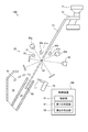
- FIG. 1 is a schematic diagram showing a schematic configuration of an optical sorter (hereinafter, simply referred to as a sorter) 10 as the first embodiment of the present invention.
- the sorter 10 is used to sort foreign substances (for example, pebbles, mud, glass pieces, etc.) and defective products (for example, immature grains, colored grains, etc.) from rice as a sorting target. ..
- the object to be sorted is not limited to rice, and may be any granular material (for example, grains other than rice, plastic, etc.).
- the sorting machine 10 includes an optical detection unit 20, a storage tank 71, a feeder 72, a chute 73, a non-defective product discharge gutter 74, a defective product discharge gutter 75, an ejector 76, and a control device. It has 80 and.
- the control device 80 controls the overall operation of the sorter 10.
- the control device 80 also functions as an integrating unit 81, a first determination unit 82, and a second determination unit 83.
- the function of the control device 80 may be realized by the CPU executing a predetermined program, or may be realized by a dedicated circuit. At least a part of the integrating unit 81, the first determination unit 82, and the second determination unit 83 may be realized by one integrated device.
- the first determination unit 82 and the second determination unit 83 may have two functions realized by one CPU.
- the integrating unit 81, the first determination unit 82, and the second determination unit 83 may be realized as individual devices. The details of the function of the control device 80 will be described later.
- the storage tank 71 temporarily stores the sorting object (hereinafter, simply referred to as an object) 90.
- the feeder 72 supplies the object 90 stored in the storage tank 71 onto the chute 73.
- the optical detection unit 20 irradiates the object 90 that has slipped off the chute 73 with light, and the light associated with the object 90 (specifically, the transmitted light transmitted through the object 90 and / or). The reflected light reflected by the object 90) is detected.
- This detection result is input to the control device 80. Based on this detection result, the control device 80 determines whether the object 90 is a good product (that is, rice grains with relatively high quality), or a foreign substance (that is, a non-rice grain) or a defective product (that is, quality). Is a relatively low grain of rice). This determination is made for each of the objects 90.
- the ejector 76 injects air 77 toward the object 90. As a result, the object 90 is blown off, deviates from the drop trajectory from the chute 73, and is guided to the defective product discharge gutter 75. On the other hand, when the object 90 is determined to be a non-defective product, the air 77 is not injected. Therefore, the object 90 determined to be a non-defective product is guided to the non-defective product discharge gutter 74 without changing the fall trajectory.
- the optical detection unit 20 includes a first light source 30, second light sources 40a and 40b, a first optical sensor 50, a second optical sensor 60a and 60b, and a first It includes an optical filter 51 and second optical filters 61a and 61b.
- the first optical sensor 50 is a general-purpose color CCD sensor in this embodiment.
- the first optical sensor 50 is a line sensor in this embodiment, but may be an area sensor.
- the first optical sensor 50 includes an optical element for detecting light having a wavelength corresponding to red (hereinafter referred to as R element) and an optical element for detecting light having a wavelength corresponding to green (hereinafter referred to as R element). , G element) and an optical element (hereinafter, referred to as B element) for detecting light having a wavelength corresponding to blue.
- R, G, and B mean R, G, and B in the RGB color space, respectively.
- Each of these optical elements includes a condenser lens, a color filter, and a photoelectric conversion element.
- Each of the color filters has a property of transmitting light having a wavelength corresponding to the color of light to be detected (for example, red in the case of an R element) and not transmitting light of other wavelengths.
- a spectroscope such as a dichroic prism may be used instead of the color filter.
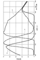
- FIG. 2 shows an example of the spectral sensitivity characteristics of the R element, G element, and B element of the first optical sensor 50.
- each of the three types of devices has a peak of spectral sensitivity in the visible wavelength region.
- the visible wavelength region is, for example, a region having a wavelength of 400 nm or more and 760 nm or less.
- the R element has a peak of spectral sensitivity near 620 nm.
- the G element has a peak of spectral sensitivity near 520 nm.
- the B element has a peak of spectral sensitivity near 470 nm.
- Each of these elements has a non-zero spectral sensitivity even in a predetermined wavelength range in the invisible wavelength region (that is, a wavelength region other than the visible wavelength region).
- a predetermined wavelength range in the invisible wavelength region that is, a wavelength region other than the visible wavelength region.
- each of the R element, the G element, and the B element has a relative sensitivity of about 0.35 with respect to light having a wavelength of 850 nm (more specifically, near infrared light). doing.
- the second optical sensors 60a and 60b have the same specifications as the first optical sensor 50 in this embodiment. Therefore, the second optical sensors 60a and 60b include R elements, G elements, and B elements having the same specifications as the first optical sensor 50, and these elements have the spectral sensitivity characteristics illustrated in FIG. Have.
- the first light source 30 emits the first light 31 toward the object 90.
- the first light 31 has a wavelength within the above-mentioned predetermined wavelength range (that is, a wavelength range in the invisible wavelength region in which the R element, G element, and B element of the first optical sensor 50 have non-zero spectral sensitivity). have.
- the first light source 30 is a near infrared light source. Therefore, the first light 31 is also referred to as near infrared light 31.
- the output peak of the first light source 30 is in the invisible wavelength region (in this embodiment, at a wavelength of 850 nm).
- the first light source 30 is an LED in this embodiment, but any other light emitting element (for example, a halogen lamp) may be used.
- the first light 31 may include light having a wavelength in the visible wavelength region in addition to light having a wavelength in the invisible wavelength region.
- the second light source 40a emits the second light 41a toward the object 90.
- the second light 41a has a wavelength within the visible wavelength region. Therefore, the second light 41a is also referred to as visible light 41a.
- the output peak of the second light source 40a is in the visible wavelength region.
- the second light source 40a is a so-called color LED capable of emitting red, green, and blue light, respectively.
- the second light source 40a may be any other light emitting element (for example, a halogen lamp).
- the second light source 40b has the same specifications as the second light source 40a, and emits a second light 41b (also referred to as visible light 41b) having a wavelength within the visible wavelength region toward the object 90. To do.
- the second light 41a and 41b may include light having a wavelength in the invisible wavelength region in addition to light having a wavelength in the visible wavelength region.
- the first optical filter 51 is arranged on the optical path of the light incident on the first optical sensor 50.
- the first optical filter 51 cuts light having a wavelength within the visible wavelength region. That is, light having a wavelength in the invisible wavelength region (near infrared wavelength region in this embodiment) passes through the first optical filter 51, but light having a wavelength in the visible wavelength region is transmitted through the first optical filter. It does not pass through 51. Therefore, the first optical sensor 50 can detect only near-infrared light.
- the second optical filters 61a and 61b are arranged on the optical path of the light incident on the second optical sensors 60a and 60b, respectively.
- the second optical filters 61a and 61b cut light having a wavelength within the invisible wavelength region. That is, the light having a wavelength within the visible wavelength region passes through the second optical filters 61a and 61b, but the light having a wavelength in the invisible wavelength region (in the present embodiment, the near infrared wavelength region) is the second optical filter. It does not pass through the optical filters 61a and 61b. Therefore, the second optical sensors 60a and 60b can detect only visible light.
- the first light source 30, the second light source 40a, and the second optical sensor 60a are unilateral with respect to the transfer path of the object 90 (in other words, the fall locus from the chute 73). It is located on the front side (also called the front side).
- the second light source 40b, the first optical sensor 50, and the second optical sensor 60b are arranged on the other side (also referred to as the rear side) with respect to the transfer path of the object 90.
- the first optical sensor 50 on the rear side detects near-infrared light 31 emitted from the first light source 30 on the front side, transmitted through the object 90, and further transmitted through the first optical filter 51.
- the second optical sensor 60a on the front side is the visible light 41a emitted from the second light source 40a on the front side, reflected by the object 90, and transmitted through the second optical filter 61a, and the second light source on the rear side. Visible light 41b emitted from the light source 40b, transmitted through the object 90, and further transmitted through the second optical filter 61a is detected.
- the second optical sensor 60b on the rear side is the visible light 41b emitted from the second light source 40b on the rear side, reflected by the object 90, and transmitted through the second optical filter 61b, and the second light source on the front side. Visible light 41a emitted from the light source 40a, transmitted through the object 90, and further transmitted through the second optical filter 61b is detected.
- the first optical sensor 50 and the second optical sensors 60a and 60b perform a plurality of scans on one object 90. By synthesizing the images obtained in each scan, the entire image of the one object 90 is acquired.
- the first light source 30 and the second light sources 40a and 40b are constantly lit over the entire scanning period of the first optical sensor 50 and the second optical sensors 60a and 60b.
- the method of lighting the first light source 30 and the second light sources 40a and 40b is not particularly limited.
- the outputs of the first optical sensor 50 and the second optical sensors 60a and 60b, that is, analog signals representing the detected light intensity are converted into digital signals by an AC / DC converter (not shown).
- This digital signal (in other words, the gradation value corresponding to the analog signal) is input to the control device 80.
- the control device 80 foreign matter and / or defective products are determined based on the visible light 41a and 41b associated with the object 90, and the foreign matter is determined based on the near-infrared light 31 associated with the object 90. And / or a defective product is determined.
- the second determination unit 83 determines that the object 90 is based on the analog signal obtained via the second optical sensors 60a, 60b (in other words, using the gradation value represented by the digital signal). Determine whether it is a good product, a foreign substance, or a defective product.
- the second determination unit 83 determines the R gradation value, the G gradation value, and the B gradation obtained via the R element, the G element, and the B element of the second optical sensors 60a and 60b. Foreign matter and / or defective products are determined by comparing the value with a predetermined threshold value. Any known determination method can be adopted as this determination method.
- the integrating unit 81 integrates the R gradation value, the G gradation value, and the B gradation value obtained via the R element, the G element, and the B element of the first optical sensor 50.
- the integrated value IV is calculated according to the following equation (1).
- R, G, and B represent R gradation value, G gradation value, and B gradation value, respectively.
- a, b, and c are weighting coefficients, and are set to values larger than 0, respectively.
- This integration is performed in pixel units of the image data obtained by the first optical sensor 50.
- IV aR + bG + cB ... (1)
- the integrated value IV is a value obtained by simply adding the R gradation value, the G gradation value, and the B gradation value obtained via the R element, the G element, and the B element of the first optical sensor 50. is there.
- each of the R element, G element, and B element of the first optical sensor 50 with respect to the light having a wavelength of 850 nm (near infrared light 31) emitted from the first light source 30. It has a relative sensitivity of about 0.35. The sum of these relative sensitivities is 1.05 ( 0.35 + 0.35 + 0.35). Therefore, the integrated value IV is a large gradation value obtained when each of the R element, G element, and B element of the second optical sensors 60a and 60b detects light having a wavelength that matches the peak sensitivity. It has the same size as.
- the first determination unit 82 determines whether the object 90 is a non-defective product, a foreign substance, or a defective product based on the integrated value IV. More specifically, the first determination unit 82 determines a foreign substance and / or a defective product by comparing the integrated value IV with a predetermined threshold value. Any known determination method can be adopted as this determination method.
- the near-infrared light 31 associated with the object 90 is generated by the first optical sensor 50 including the R element, the G element, and the B element having the peak of the spectral sensitivity in the visible wavelength region. Detected.
- the near-infrared light 31 can be detected without using an optical sensor including an optical element having a peak of spectral sensitivity in the invisible wavelength region.
- an optical sensor having an R element, a G element, and a B element having a peak of spectral sensitivity in the visible wavelength region is much cheaper than an optical sensor having an element having a peak of spectral sensitivity in the invisible wavelength region. is there.
- the first optical sensor 50 including the R element, the G element, and the B element having the peak of the spectral sensitivity in the visible wavelength region is used for detecting the near infrared light 31.
- the manufacturing cost of the sorter 10 can be reduced.
- the spectral sensitivity of the first optical sensor 50 in the near-infrared wavelength region is smaller than the spectral sensitivity in the visible wavelength region
- the R gradation value, the G gradation value, and B are used to determine foreign matter and / or defective products.
- the integrated value IV obtained by integrating the gradation values is used. That is, the gradation value used for the determination is increased by integration. Therefore, it is possible to suppress a decrease in determination accuracy due to insufficient sensitivity.
- the output signals from the R element, G element, and B element may contain random noise, an event occurs in which the noise cancels each other out by integrating the R gradation value, the G gradation value, and the B gradation value. Therefore, the noise is less likely to be amplified as compared with the case where only one of the R gradation value, the G gradation value and the B gradation value is simply increased by multiplying by a predetermined coefficient. Therefore, it is possible to suppress a decrease in determination accuracy due to noise amplification.
- the sorter 10 since the sorter 10 includes the first optical filter 51 and the second optical filters 61a and 61b, even if the first light source 30 and the second light sources 40a and 40b are turned on at the same time, the first light source 30 and the second light sources 40a and 40b are turned on at the same time.
- the optical sensor 50 of 1 can detect only the near-infrared light 31 associated with the object 90, and the second optical sensors 60a and 60b can detect only the visible light 41a and 41b associated with the object 90. Can be detected. Therefore, it is possible to detect visible light and detect invisible light while the object 90 is dropped from the chute 73 once.
- the first optical sensor 50 has the same specifications as the second optical sensors 60a and 60b. Therefore, it is possible to simplify the procurement of parts at the manufacturing stage of the sorter 10. As a result, the manufacturing cost can be reduced.
- the weighting coefficients a, b, and c may be set to a value other than 1.
- the weighting coefficients a, b, and c may be set to a value larger than 1, and the integrated value IV may be increased. In this case, if the weighting coefficients a, b, and c are set to the same value larger than 1, the effect of canceling the noise can be preferably obtained as in the above-described embodiment.
- the weighting coefficient a, b, and c may be set to a value smaller than 1.
- the weighting coefficients a, b, and c may be set to the same value.
- a, b, and c may be set to a value of 0 or more, provided that two or more of a, b, and c are not 0.
- any one of a, b, and c may be 0.
- the analog signals output from the R element, the G element, and the B element may be integrated and amplified by the addition circuit.
- the integrated value IV only two gradation values of the R gradation value, the G gradation value and the B gradation value may be integrated.
- the first optical sensor 50 may be arranged only on the front side, or may be arranged on both the front side and the rear side.
- the first light source 30 may be arranged only on the rear side, or may be arranged on both the front side and the rear side.
- one light source for example, a halogen lamp
- a halogen lamp that emits light having a wavelength in the invisible wavelength region and light having a wavelength in the visible wavelength region
- FIG. 3 is a schematic diagram showing a schematic configuration of a sorter 100 as a second embodiment of the present invention.
- the sorter 100 differs from the first embodiment only in that it does not include the first optical filter 51 and the second optical filters 61a and 61b and that it includes a control device 180 instead of the control device 80. There is.
- the sorting machine 100 will be described only with respect to the differences from the first embodiment.
- the control device 180 is different from the control device 80 in that the first light source 30 and the second light sources 40a and 40b are controlled so as to be turned on intermittently.
- FIG. 4 is a timing chart showing the lighting timings of the first light source 30 and the second light sources 40a and 40b.
- FIG. 5 is an explanatory diagram showing the relationship between one object 90 and the scan numbers (numbers indicating the number of scans) of the first optical sensor 50 and the second optical sensors 60a and 60b. is there.
- image data is acquired by scanning one object 90 eight times (illustrated as a smaller number than the actual number for simplification of explanation). Will be done.
- the numbers 1 to 8 shown in FIG. 5 indicate the scanning numbers from which the image data of the corresponding area is acquired. For example, the area marked with "1" indicates that the image data is acquired by the first scan.
- the first light source 30 is turned on only during the scanning period having an odd number of scan numbers (indicated as ON in the figure) and turned off during the scanning period having an even number of scan numbers. (Indicated as OFF in the figure).
- the second light sources 40a and 40b are turned on only during the scanning period having an even scanning number, and turned off during the scanning period having an odd scanning number.
- the second light sources 40a and 40b are turned on or off at the same time. That is, the first light source 30 and the second light sources 40a and 40b are turned on alternately. In other words, the first light source 30 and the second light sources 40a and 40b are turned on exclusively with respect to each other.
- the first optical sensor 50 detects the near-infrared light 31 emitted from the first light source 30 only during the scanning period having an odd scanning number
- the second optical sensor 60a At 60b, visible light 41a, 41b emitted from the second light sources 40a, 40b is detected only during the scanning period having an even number of scan numbers. Therefore, the integration unit 81 and the first determination unit 82 hatch the signal acquired by the first optical sensor 50 during the scanning period having an odd number of scan numbers (the region of the image obtained by this signal is hatched in FIG. 5). The integration process and the determination process described in the first embodiment are performed using only (shown). Similarly, the second determination unit 83 performs the determination process described in the first embodiment using only the signals acquired by the second optical sensors 60a and 60b during the scanning period having an even number of scan numbers.
- the resolutions of the first optical sensor 50 and the second optical sensors 60a and 60b are reduced to half as compared with the first embodiment, the near infrared light 31 and the visible light 41a and 41b Does not interfere with. Therefore, while the object 90 is dropped from the chute 73 once, the first optical sensor 50 can detect only the near-infrared light 31 associated with the object 90, and the second optical sensor 60a , 60b can detect only visible light 41a, 41b associated with the object 90. Moreover, since the first optical filter 51 and the second optical filters 61a and 61b are not required, the manufacturing cost can be further reduced.
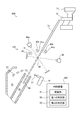
- FIG. 6 is a schematic diagram showing a schematic configuration of a sorter 200 as a third embodiment of the present invention.
- the sorter 200 is different from the second embodiment only in that the second optical sensor 60b is not provided and that the control device 280 is provided instead of the control device 180.
- the sorting machine 200 will be described only in terms of differences from the second embodiment.
- the control device 280 controls the first light source 30 and the second light sources 40a and 40b so as to be intermittently lit in the same manner as the control device 180 (that is, in the manner shown in FIG. 4).
- the first optical sensor 50 arranged on the rear side also plays the role of the second optical sensor 60b. That is, the first optical sensor 50 detects the near-infrared light 31 emitted from the first light source 30 during the scanning period having an odd number of scan numbers, and the second optical sensor 50 detects the near infrared light 31 emitted from the first light source 30 during the scanning period having an even number of scan numbers.
- the visible light 41a, 41b emitted from the light sources 40a, 40b of the above is detected.
- the integrating unit 81 and the first determination unit 82 use only the signals acquired by the first optical sensor 50 during the scanning period having an odd number of scanning numbers, and the first determination unit 82 is used.
- the integration process and the determination process described in the embodiment are performed.
- the second determination unit 83 is acquired by the signal acquired by the second optical sensor 60a in the scanning period having an even scanning number and by the first optical sensor 50 in the scanning period having an odd scanning number.
- the determination process described in the first embodiment is performed using the signal.
- the first optical sensor 50 can be shared for both the detection of the near-infrared light 31 and the detection of the visible lights 41a and 41b, so that the first optical sensor 50 can be shared as compared with the second embodiment.
- the manufacturing cost can be reduced by the cost of the second optical sensor 60b.
- the object 90 may be dropped twice to detect visible light and detect invisible light. For example, at the time of the first fall, only the first light source 30 is continuously lit, the near infrared light 31 is detected by the first optical sensor 50, and at the time of the second fall, only the second light sources 40a and 40b are turned on. Is continuously lit, and visible light 41a and 41b may be detected by the first optical sensor 50.
- the first optical sensor 50 instead of using the first optical sensor 50 in which each of the R element, the G element and the B element has a non-zero spectral sensitivity in the near infrared wavelength region, two types of the R element, the G element and the B element are used.
- a first optical sensor may be used in which only one of the elements has a non-zero spectral sensitivity in the near infrared wavelength region. Even in this case, by integrating the signals or gradation values acquired through the two types of elements, it is possible to suppress a decrease in determination accuracy due to insufficient sensitivity.
- each of the R element, the G element and the B element has a non-zero spectral sensitivity in the near infrared wavelength region
- each of the R element, the G element and the B element has a spectral sensitivity.
- a first light source having a wavelength in the far-infrared wavelength region or the ultraviolet wavelength region is used.
- the filtering characteristics of the first optical filter 51 can be appropriately changed according to the wavelength range of the light emitted from the first light source used. Even with such a configuration, the far-infrared wavelength region or the ultraviolet wavelength region can be detected by using an inexpensive optical sensor while ensuring the necessary determination accuracy.
- first optical sensor 50 and / or the second optical sensors 60a and 60b other types of optical sensors such as a color CMOS sensor may be used instead of the color CCD sensor.
- First light source 31 ... First light (near infrared light) 40a, 40b ... Second light source 41a, 41b ... Second light (visible light) 50 ... 1st optical sensor 51 ... 1st optical filter 60a, 60b ... 2nd optical sensor 61a, 61b ... 2nd optical filter 71 ... Storage tank 72 ... Feeder 73 ... Shoot 74 ... Good product discharge trough 75 ... Defective product discharge trough 76 ... Ejector 77 ... Air 80, 180, 280 ... Control device 81 ... Integration unit 82 .. .First judgment unit 83 ... Second judgment unit 90 ... Object
Landscapes
- Physics & Mathematics (AREA)
- Health & Medical Sciences (AREA)
- Life Sciences & Earth Sciences (AREA)
- Chemical & Material Sciences (AREA)
- Analytical Chemistry (AREA)
- Biochemistry (AREA)
- General Health & Medical Sciences (AREA)
- General Physics & Mathematics (AREA)
- Immunology (AREA)
- Pathology (AREA)
- Sorting Of Articles (AREA)
- Investigating Materials By The Use Of Optical Means Adapted For Particular Applications (AREA)
Abstract
Cette machine de tri optique comporte un premier capteur optique comprenant un élément R, un élément G et un élément B. L'élément R, l'élément G et l'élément B ont chacun un pic de sensibilité spectrale dans la région de longueur d'onde visible. Au moins deux éléments parmi l'élément R, l'élément G et l'élément B ont une sensibilité spectrale non nulle dans une région de longueur d'onde prescrite au sein des régions de longueur d'onde invisible. La machine de tri optique comprend en outre : une première source de lumière qui émet une première lumière ayant une longueur d'onde dans une région de longueur d'onde prescrite vers un objet qui est sélectionné ; une unité d'intégration qui intègre au moins une partie d'un signal acquis au moyen d'au moins deux éléments, ou au moins une partie d'une valeur de gradation correspondant audit signal, lorsque la première lumière est émise par la première source de lumière ; et une première unité d'évaluation qui évalue un corps étranger et/ou un produit défectueux sur la base du signal ou de la valeur de gradation intégrée par l'unité d'intégration.
Priority Applications (1)
| Application Number | Priority Date | Filing Date | Title |
|---|---|---|---|
| CN202080081194.6A CN114729901A (zh) | 2019-11-29 | 2020-11-25 | 光学式分选机 |
Applications Claiming Priority (2)
| Application Number | Priority Date | Filing Date | Title |
|---|---|---|---|
| JP2019217135A JP7354802B2 (ja) | 2019-11-29 | 2019-11-29 | 光学式選別機 |
| JP2019-217135 | 2019-11-29 |
Publications (1)
| Publication Number | Publication Date |
|---|---|
| WO2021106964A1 true WO2021106964A1 (fr) | 2021-06-03 |
Family
ID=76087415
Family Applications (1)
| Application Number | Title | Priority Date | Filing Date |
|---|---|---|---|
| PCT/JP2020/043910 WO2021106964A1 (fr) | 2019-11-29 | 2020-11-25 | Machine de tri optique |
Country Status (3)
| Country | Link |
|---|---|
| JP (1) | JP7354802B2 (fr) |
| CN (1) | CN114729901A (fr) |
| WO (1) | WO2021106964A1 (fr) |
Families Citing this family (2)
| Publication number | Priority date | Publication date | Assignee | Title |
|---|---|---|---|---|
| JP2023000672A (ja) * | 2021-06-18 | 2023-01-04 | 株式会社サタケ | 選別機、不良品の判別方法、および、選別方法 |
| JP2023136102A (ja) * | 2022-03-16 | 2023-09-29 | 株式会社サタケ | 測定装置および選別装置 |
Citations (7)
| Publication number | Priority date | Publication date | Assignee | Title |
|---|---|---|---|---|
| JPH11298800A (ja) * | 1998-04-10 | 1999-10-29 | Nikon Corp | 撮像素子およびこれを用いた撮像装置 |
| JP2006109120A (ja) * | 2004-10-06 | 2006-04-20 | Funai Electric Co Ltd | 赤外線撮像装置 |
| JP2007333464A (ja) * | 2006-06-13 | 2007-12-27 | Mitsubishi Electric Corp | 2波長イメージセンサ |
| JP2011507353A (ja) * | 2007-12-05 | 2011-03-03 | エレクトロ サイエンティフィック インダストリーズ インコーポレーテッド | カラーモザイク撮像器から全色性応答を達成するための方法および装置 |
| JP2014157119A (ja) * | 2013-02-18 | 2014-08-28 | Satake Corp | 光学式粒状物選別機 |
| WO2016080003A1 (fr) * | 2014-11-20 | 2016-05-26 | シャープ株式会社 | Élément d'imagerie à semi-conducteurs |
| JP2019103004A (ja) * | 2017-12-04 | 2019-06-24 | キヤノン株式会社 | 撮像装置、撮像装置の制御方法およびプログラム |
Family Cites Families (3)
| Publication number | Priority date | Publication date | Assignee | Title |
|---|---|---|---|---|
| JP2000157936A (ja) * | 1998-11-27 | 2000-06-13 | Satake Eng Co Ltd | 粒状物選別方法及び粒状物選別装置 |
| JP2003324751A (ja) * | 2002-05-07 | 2003-11-14 | Toshiba Corp | 情報入力装置 |
| JP6264234B2 (ja) * | 2014-09-02 | 2018-01-24 | 株式会社Jvcケンウッド | 撮像装置、撮像装置の制御方法及び制御プログラム |
-
2019
- 2019-11-29 JP JP2019217135A patent/JP7354802B2/ja active Active
-
2020
- 2020-11-25 WO PCT/JP2020/043910 patent/WO2021106964A1/fr active Application Filing
- 2020-11-25 CN CN202080081194.6A patent/CN114729901A/zh active Pending
Patent Citations (7)
| Publication number | Priority date | Publication date | Assignee | Title |
|---|---|---|---|---|
| JPH11298800A (ja) * | 1998-04-10 | 1999-10-29 | Nikon Corp | 撮像素子およびこれを用いた撮像装置 |
| JP2006109120A (ja) * | 2004-10-06 | 2006-04-20 | Funai Electric Co Ltd | 赤外線撮像装置 |
| JP2007333464A (ja) * | 2006-06-13 | 2007-12-27 | Mitsubishi Electric Corp | 2波長イメージセンサ |
| JP2011507353A (ja) * | 2007-12-05 | 2011-03-03 | エレクトロ サイエンティフィック インダストリーズ インコーポレーテッド | カラーモザイク撮像器から全色性応答を達成するための方法および装置 |
| JP2014157119A (ja) * | 2013-02-18 | 2014-08-28 | Satake Corp | 光学式粒状物選別機 |
| WO2016080003A1 (fr) * | 2014-11-20 | 2016-05-26 | シャープ株式会社 | Élément d'imagerie à semi-conducteurs |
| JP2019103004A (ja) * | 2017-12-04 | 2019-06-24 | キヤノン株式会社 | 撮像装置、撮像装置の制御方法およびプログラム |
Also Published As
| Publication number | Publication date |
|---|---|
| CN114729901A (zh) | 2022-07-08 |
| JP2021085846A (ja) | 2021-06-03 |
| JP7354802B2 (ja) | 2023-10-03 |
Similar Documents
| Publication | Publication Date | Title |
|---|---|---|
| US6784996B2 (en) | Color sorting apparatus for granular object with optical detection device consisting of CCD linear sensor | |
| JP2008302314A (ja) | 光学式米粒選別機 | |
| WO2021106964A1 (fr) | Machine de tri optique | |
| KR20010067172A (ko) | 2 개 이상의 다른 임계 레벨로 입상물들을 선별하는 방법및 장치 | |
| JP2009115613A (ja) | 異物検査装置 | |
| KR102240757B1 (ko) | Lctf-기반 다분광 영상 기술을 이용한 가공 채소류 내 포함된 이물질 실시간 검출 시스템 | |
| JPH0796253A (ja) | 豆類色彩選別機 | |
| JP7544358B2 (ja) | 撮像装置、検査装置及び撮像方法 | |
| JP7333771B2 (ja) | 領域抽出装置及び方法並びに対象物検出装置及び方法 | |
| WO2021117544A1 (fr) | Machine de tri optique | |
| EP0660277B1 (fr) | Méthode et dispositif pour la caractérisation et la différenciation de billets de banque et documents légaux | |
| WO2021125133A1 (fr) | Machine de tri optique | |
| JP7608742B2 (ja) | 光学式選別機 | |
| JP7521570B2 (ja) | 光学式選別機 | |
| JP7434889B2 (ja) | 光学式選別機 | |
| JP2005186053A (ja) | 粒状物色彩選別機 | |
| WO2023100805A1 (fr) | Dispositif d'imagerie, dispositif d'inspection, et procédé d'imagerie | |
| WO2023176751A1 (fr) | Dispositif de mesure et dispositif de sélection | |
| TW202409544A (zh) | 拍攝裝置、檢查裝置、拍攝條件決定方法及拍攝方法 | |
| JP2024158828A (ja) | 透明物品の撮像装置及び透明物品の検査装置 | |
| JP3015871U (ja) | 選別装置 | |
| TW202232372A (zh) | 拍攝裝置、檢查裝置及拍攝方法 | |
| CN112620160A (zh) | 大米物料的检测系统、方法及色选机 | |
| JP2001012928A (ja) | 板状物品検査装置 |
Legal Events
| Date | Code | Title | Description |
|---|---|---|---|
| 121 | Ep: the epo has been informed by wipo that ep was designated in this application |
Ref document number: 20893931 Country of ref document: EP Kind code of ref document: A1 |
|
| NENP | Non-entry into the national phase |
Ref country code: DE |
|
| 122 | Ep: pct application non-entry in european phase |
Ref document number: 20893931 Country of ref document: EP Kind code of ref document: A1 |