WO2023100805A1 - Dispositif d'imagerie, dispositif d'inspection, et procédé d'imagerie - Google Patents
Dispositif d'imagerie, dispositif d'inspection, et procédé d'imagerie Download PDFInfo
- Publication number
- WO2023100805A1 WO2023100805A1 PCT/JP2022/043763 JP2022043763W WO2023100805A1 WO 2023100805 A1 WO2023100805 A1 WO 2023100805A1 JP 2022043763 W JP2022043763 W JP 2022043763W WO 2023100805 A1 WO2023100805 A1 WO 2023100805A1
- Authority
- WO
- WIPO (PCT)
- Prior art keywords
- image
- light
- light source
- imaging
- camera
- Prior art date
Links
Images


Classifications
-
- G—PHYSICS
- G01—MEASURING; TESTING
- G01N—INVESTIGATING OR ANALYSING MATERIALS BY DETERMINING THEIR CHEMICAL OR PHYSICAL PROPERTIES
- G01N21/00—Investigating or analysing materials by the use of optical means, i.e. using sub-millimetre waves, infrared, visible or ultraviolet light
- G01N21/84—Systems specially adapted for particular applications
- G01N21/88—Investigating the presence of flaws or contamination
- G01N21/90—Investigating the presence of flaws or contamination in a container or its contents
-
- G—PHYSICS
- G03—PHOTOGRAPHY; CINEMATOGRAPHY; ANALOGOUS TECHNIQUES USING WAVES OTHER THAN OPTICAL WAVES; ELECTROGRAPHY; HOLOGRAPHY
- G03B—APPARATUS OR ARRANGEMENTS FOR TAKING PHOTOGRAPHS OR FOR PROJECTING OR VIEWING THEM; APPARATUS OR ARRANGEMENTS EMPLOYING ANALOGOUS TECHNIQUES USING WAVES OTHER THAN OPTICAL WAVES; ACCESSORIES THEREFOR
- G03B11/00—Filters or other obturators specially adapted for photographic purposes
-
- G—PHYSICS
- G03—PHOTOGRAPHY; CINEMATOGRAPHY; ANALOGOUS TECHNIQUES USING WAVES OTHER THAN OPTICAL WAVES; ELECTROGRAPHY; HOLOGRAPHY
- G03B—APPARATUS OR ARRANGEMENTS FOR TAKING PHOTOGRAPHS OR FOR PROJECTING OR VIEWING THEM; APPARATUS OR ARRANGEMENTS EMPLOYING ANALOGOUS TECHNIQUES USING WAVES OTHER THAN OPTICAL WAVES; ACCESSORIES THEREFOR
- G03B15/00—Special procedures for taking photographs; Apparatus therefor
- G03B15/02—Illuminating scene
- G03B15/03—Combinations of cameras with lighting apparatus; Flash units
- G03B15/05—Combinations of cameras with electronic flash apparatus; Electronic flash units
-
- G—PHYSICS
- G03—PHOTOGRAPHY; CINEMATOGRAPHY; ANALOGOUS TECHNIQUES USING WAVES OTHER THAN OPTICAL WAVES; ELECTROGRAPHY; HOLOGRAPHY
- G03B—APPARATUS OR ARRANGEMENTS FOR TAKING PHOTOGRAPHS OR FOR PROJECTING OR VIEWING THEM; APPARATUS OR ARRANGEMENTS EMPLOYING ANALOGOUS TECHNIQUES USING WAVES OTHER THAN OPTICAL WAVES; ACCESSORIES THEREFOR
- G03B17/00—Details of cameras or camera bodies; Accessories therefor
- G03B17/02—Bodies
- G03B17/17—Bodies with reflectors arranged in beam forming the photographic image, e.g. for reducing dimensions of camera
-
- G—PHYSICS
- G03—PHOTOGRAPHY; CINEMATOGRAPHY; ANALOGOUS TECHNIQUES USING WAVES OTHER THAN OPTICAL WAVES; ELECTROGRAPHY; HOLOGRAPHY
- G03B—APPARATUS OR ARRANGEMENTS FOR TAKING PHOTOGRAPHS OR FOR PROJECTING OR VIEWING THEM; APPARATUS OR ARRANGEMENTS EMPLOYING ANALOGOUS TECHNIQUES USING WAVES OTHER THAN OPTICAL WAVES; ACCESSORIES THEREFOR
- G03B19/00—Cameras
- G03B19/02—Still-picture cameras
- G03B19/04—Roll-film cameras
- G03B19/07—Roll-film cameras having more than one objective
-
- H—ELECTRICITY
- H04—ELECTRIC COMMUNICATION TECHNIQUE
- H04N—PICTORIAL COMMUNICATION, e.g. TELEVISION
- H04N23/00—Cameras or camera modules comprising electronic image sensors; Control thereof
- H04N23/10—Cameras or camera modules comprising electronic image sensors; Control thereof for generating image signals from different wavelengths
-
- H—ELECTRICITY
- H04—ELECTRIC COMMUNICATION TECHNIQUE
- H04N—PICTORIAL COMMUNICATION, e.g. TELEVISION
- H04N23/00—Cameras or camera modules comprising electronic image sensors; Control thereof
- H04N23/45—Cameras or camera modules comprising electronic image sensors; Control thereof for generating image signals from two or more image sensors being of different type or operating in different modes, e.g. with a CMOS sensor for moving images in combination with a charge-coupled device [CCD] for still images
-
- H—ELECTRICITY
- H04—ELECTRIC COMMUNICATION TECHNIQUE
- H04N—PICTORIAL COMMUNICATION, e.g. TELEVISION
- H04N23/00—Cameras or camera modules comprising electronic image sensors; Control thereof
- H04N23/50—Constructional details
- H04N23/54—Mounting of pick-up tubes, electronic image sensors, deviation or focusing coils
-
- H—ELECTRICITY
- H04—ELECTRIC COMMUNICATION TECHNIQUE
- H04N—PICTORIAL COMMUNICATION, e.g. TELEVISION
- H04N23/00—Cameras or camera modules comprising electronic image sensors; Control thereof
- H04N23/50—Constructional details
- H04N23/55—Optical parts specially adapted for electronic image sensors; Mounting thereof
-
- H—ELECTRICITY
- H04—ELECTRIC COMMUNICATION TECHNIQUE
- H04N—PICTORIAL COMMUNICATION, e.g. TELEVISION
- H04N23/00—Cameras or camera modules comprising electronic image sensors; Control thereof
- H04N23/56—Cameras or camera modules comprising electronic image sensors; Control thereof provided with illuminating means
-
- H—ELECTRICITY
- H04—ELECTRIC COMMUNICATION TECHNIQUE
- H04N—PICTORIAL COMMUNICATION, e.g. TELEVISION
- H04N23/00—Cameras or camera modules comprising electronic image sensors; Control thereof
- H04N23/80—Camera processing pipelines; Components thereof
- H04N23/84—Camera processing pipelines; Components thereof for processing colour signals
- H04N23/85—Camera processing pipelines; Components thereof for processing colour signals for matrixing
Definitions
- the present disclosure relates to an imaging device, an inspection device, and an imaging method for imaging a subject.
- Patent Documents 1 and 2 disclose imaging devices that capture images of a subject from a plurality of different directions. These imaging devices are equipped with a plurality of (for example, four) cameras capable of imaging the entire outer peripheral surface of a subject. An imaging device inspects a subject for defects or the like based on images captured by a plurality of cameras.
- Patent Document 3 discloses an imaging apparatus equipped with a camera that receives transmitted light that has passed through a subject, such as a glass container in which light from a light source has optical transparency, and captures a transmitted image of the subject. .
- An imaging apparatus for solving the above problems is an imaging apparatus including two cameras for capturing two transmitted images of a subject by receiving light transmitted through the subject from opposite directions, wherein the subject is viewed in a first direction. a second light source that emits light that passes through the subject in a second direction opposite to the first direction; and a second light source that emits light that passes through the subject in the first direction. a first camera, which is one of the two cameras, for receiving first transmitted light and capturing a first image; and receiving second transmitted light transmitted through the subject in the second direction.
- a second camera which is the other of the two cameras, for capturing a second image
- a first half mirror that reflects along an optical path toward the first camera and allows transmission of the light at a position in the middle of the optical path of the light from the second light source toward the subject; turning off the first light source; below, the second transmitted light is reflected along the optical path toward the second camera at a position in the middle of the optical path of the second transmitted light, and in the middle of the optical path of the light from the first light source toward the subject and a second half mirror that allows the light to pass therethrough at a position.
- the "opposite direction” is not limited to the opposite direction, and may be any direction toward the subject from both sides sandwiching the subject.
- the opposite directions are defined as angles formed by the first direction and the second direction of 130 degrees, 150 degrees, It may be 170 degrees or the like.
- the image capturing apparatus further includes a control unit, and the control unit causes the first light source and the second light source to emit light at different light emission timings, thereby causing the first image to be captured by the first camera.
- the imaging of the second image by the second camera may be performed at a different imaging timing according to the light emission timing.
- the imaging device includes M imaging units each including the first light source, the second light source, the first camera, the second camera, the first half mirror, and the second half mirror (where M is two or more). a natural number), the M imaging units are arranged such that the first optical axes from the subject to the first half mirror are at different angles when the imaging units are imaged by the first camera, The M imaging units may be configured to be capable of imaging the subject from 2M different directions.
- the subject can be imaged from 2M (M ⁇ 2) different directions. Since 2M is 4 or more, it is possible to reliably image an arbitrary position on the entire circumference of the object.
- the imaging device further includes a third light source capable of irradiating the subject with light, and the first camera reflects the light emitted from the third light source to the subject on the surface of the subject and After being reflected by a half mirror and then received by the first camera, a third image is captured, and the second camera reflects the light emitted from the third light source onto the subject on the surface of the subject. At the same time, after being reflected by the second half mirror, the light may be received by the second camera to capture a fourth image.
- the first light source and the second light source each have a light diffusion panel
- the first half mirror is adhered on the light diffusion panel of the second light source
- the second half mirror may be glued onto the light emitting diffusion panel of the first light source.
- the first half mirror and the second half mirror cannot be used as mirrors, but can be used as light sources.
- the first half mirror and the second half mirror can be used as mirrors.
- the light source and the half mirror can be integrated, and the shape of the light source with the half mirror function and the degree of freedom of installation can be increased.
- the first light source and the second light source are configured to be capable of emitting near-infrared light
- the third light source is configured to be capable of emitting visible light
- the first half mirror is configured to emit visible light.
- a visible light cutting member that suppresses transmission of light is provided on a side of the first half mirror where the second light source is positioned, and the second half mirror includes a visible light cutting member that suppresses transmission of visible light. , may be provided on the side where the first light source is positioned with respect to the second half mirror.
- the visible light reflected from the subject is reflected by the light reflecting surface of the half mirror, while the visible light cutting member blocks the visible light from the light source toward the half mirror. can be captured with high quality.
- the first light source and the second light source are configured to emit near-infrared light, and the first camera and the second camera have sensitivity in the visible light region and the near-infrared region. It may be an N-band (N is a natural number of 3 or more) color camera equipped with an image sensor.
- the imaging device includes an optical bandpass filter arranged on an optical path between the image sensor of each of the first camera and the second camera and the subject, and When an imaging signal is input from one side, the imaging signal is separated into N-band image signals.
- a P-band provided that P is a natural number less than N
- a second image signal of Q band having spectral sensitivity in the visible light region.
- the conversion unit converts the first image signal including the first image and the second image signal including the third image based on the imaging signal.
- the first image signal including the second image and the second image signal including the fourth image are generated based on the imaging signal.
- the near-infrared transmission image and the visible light reflection image of the subject can be captured in one shot, and the near-infrared transmission image and the visible light reflection image of the subject can be captured from one imaging signal obtained by the one-time imaging.
- a light reflection image can be acquired.
- the inspection device includes the imaging device, and an inspection processing unit that inspects the subject based on a plurality of images captured by the first camera and the second camera of the imaging device. According to this configuration, the subject can be inspected with high accuracy using a plurality of transmission images obtained from light that passes through the subject in opposite directions.
- the image capturing method is a method of capturing an image of the subject using the image capturing device, wherein the first light source is caused to emit light while the second light source is turned off, and the first camera captures the first image of the subject.
- a first imaging step of capturing an image a second imaging step of causing the second light source to emit light while the first light source is turned off so that the second camera captures the second image of the subject;
- FIG. 1 is a schematic plan view showing an imaging device according to one embodiment
- FIG. FIG. 2 is a schematic side view showing an imaging device
- the schematic diagram which shows the structure of an inspection apparatus provided with an imaging device.
- a control table showing control details for imaging control performed by a control unit of the imaging apparatus.
- FIG. 4 is a schematic plan view showing the imaging device when the first imaging is performed
- FIG. 4 is a schematic side view showing the imaging device when the first imaging is performed
- FIG. 5 is a schematic plan view showing the imaging device when the second imaging is performed
- FIG. 11 is a schematic side view showing the imaging device when the second imaging is performed
- FIG. 3 is a configuration diagram of a camera in an example, and a graph showing the relationship between incident wavelength and relative sensitivity of an image sensor.
- FIG. 4 is a graph showing light transmittance characteristics of an optical bandpass filter; Graph showing the relative sensitivity for each color of an image sensor through an optical bandpass filter.
- 5 is a graph showing emission spectra of a near-infrared light source, which is the first light source or the second light source, and a visible light source, which is the third light source.
- FIG. 13A is a graph showing the relative sensitivity for each color of the image sensor when a visible light source and a near-infrared light source are used as light sources
- FIG. 5 is a graph showing the relative sensitivity for each band of the second imaging signal obtained by performing the above.
- FIG. 2 is a block diagram showing the functional configuration of the inspection device; FIG.
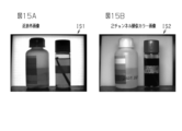
- FIG. 15A is a diagram showing a near-infrared image
- FIG. 15B is a diagram showing a two-channel pseudo-color image.
- FIG. 4 is a diagram showing a captured image of an example; The side view which shows the imaging device of the example of a change.
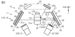
- the imaging device 11 includes a conveying device 13 that conveys an article 12 as an example of a subject, and an imaging unit 15 that images the conveyed article 12 .
- the imaging device 11 includes a transport device 13 that transports an article 12, and one or more imaging units 15 that include a set (two) of cameras 30 that capture images of the transported article 12.
- M imaging units 15 (where M is a natural number) are provided.
- 2M cameras 30 are provided.
- the 2M cameras 30 image the article 12 at the imaging position SP from 2M different directions.
- Four cameras 30 image article 12 from four different directions.
- the conveying device 13 may include a conveyor 14 that conveys the articles 12.
- the conveyor 14 conveys a plurality of articles 12 in the conveying direction X with substantially constant or irregular intervals therebetween.
- the conveyor 14 may be, for example, a belt conveyor, a roller conveyor, or the like that conveys the article 12 while it is placed thereon.
- the conveyor 14 may be one that grips and conveys the article 12 or that conveys the article 12 in a suspended state.
- the conveying device 13 may include a rejecting device that rejects from the conveyor 14 the articles 12 determined to be defective from the inspection results.
- the excluding device may be configured to eject the article 12 by pushing it out, or may be configured to eject the article 12 by blowing it off with the force of air.
- the conveyor 14 may not be provided, and a robot that places the articles 12 one by one at the imaging position SP may be provided.
- the configuration may be such that the worker places the article 12 at the imaging position SP.
- the article 12 is a container.
- the article 12 has a container body 12a and a lid 12b.
- a label 12c is attached to the outer peripheral surface of the container body 12a.
- a direction orthogonal to the transport direction X is referred to as a width direction Y
- a direction orthogonal to both the transport direction X and the width direction Y is referred to as a vertical direction Z.
- the 2M (eg, 4) cameras 30 capture images of the article 12 at the imaging position SP from 2M directions (eg, 4 directions) different from each other in the circumferential direction.
- An image of the entire circumference of the article 12 is acquired from 2M (for example, 4) images captured by the 2M cameras 30 .
- an inspection processing unit 70 (see FIG. 3), which will be described later, inspects the entire circumference of the article 12 based on 2M (for example, 4) images captured by the imaging device 11 .
- the imaging device 11 and the inspection processing unit 70 constitute the inspection device 10 for inspecting the article 12 .
- the two cameras 30 of one imaging unit 15 receive transmitted light that passes through the article 12 from opposite directions to capture two transmitted images of the article 12 .
- the M imaging units 15 basically have the same configuration. A total of 2M cameras 30 of the M imaging units 15 receive the transmitted light transmitted through the article 12 from 2M directions (for example, 4 directions) and capture 2M transmitted images. For this reason, the M imaging units 15 are symmetrical with respect to a vertical plane passing through the imaging position SP in plan view shown in FIG. It is laid out in the position where
- the two imaging units 15 are assumed to be the first imaging unit 16 and the second imaging unit 17, respectively.
- the image pickup units 16 and 17 are simply referred to as the image pickup unit 15 .
- the image capturing apparatus 11 includes, as the M image capturing units 15, a first image capturing unit 16, a second image capturing unit 17, . . .
- At least a part of the article 12 has a light transmissive property that allows light to pass therethrough.
- the light transmittance referred to here is the property of transmitting light to such an extent that the camera 30 can receive the light transmitted through the article 12 and image at least a portion of the article 12 or at least a portion of an accessory attached to the article 12.
- should have Accompanying objects include objects to be inspected, such as foreign substances mixed in the article 12 .
- the light is not limited to visible light, and may be non-visible light, for example, near-infrared light, other infrared light, ultraviolet light, or other electromagnetic waves.
- the light transmittance ⁇ (%) of the article 12 is, for example, 5% or more and less than 100%.
- the article 12 include synthetic resin, glass (amorphous), polycrystalline or single crystal ceramic, and the like.
- the article 12 may be made of wood made of a thin plate or the like through which light can pass, or may be made of metal as long as it is limited to light such as electromagnetic waves having a wavelength sufficiently shorter than that of ultraviolet light.
- the article 12 is an example of a light-transmissive container. At least a part of the container is made of a material having optical transparency.
- the container is at least partially transparent or translucent to light. Transparent may be colorless transparent or colored transparent. Translucent has a lower light transmittance ⁇ than transparent, and includes translucent white and the like.
- the container may be made of synthetic resin or glass.
- the camera 30 captures a transmitted image of the article 12 by receiving light that has passed through a portion of the article 12 that has optical transparency.
- the two cameras 30 included in the first imaging unit 16 are hereinafter also referred to as a first camera 31 and a second camera 32 .
- the two cameras 30 included in the second imaging unit 17 are also called a first camera 33 and a second camera 34 .
- the two cameras 30 are arranged so as to be shifted from the transmitted light path, which is the optical path along the direction in which the light passes through the article 12 .
- Transmitted light that has passed through the article 12 is sent to the two cameras 30 by being reflected by the half mirrors 41 and 42 .
- the two cameras 30 capture transmitted images of the article 12 by receiving light that has passed through the article 12 from opposite directions and is reflected by the reflecting surfaces 41 a and 42 a of the half mirrors 41 and 42 .
- One camera 30 captures a transmission image obtained from light that has passed through the article 12 in the first direction D1.
- Another camera 30 arranged on the opposite side of the article 12 from this camera 30 captures a transmitted image obtained from light transmitted through the article 12 in a second direction D2 opposite to the first direction D1.
- the half mirrors 41 and 42 are arranged on respective extension lines of the first direction D1 and the second direction D2 along the optical path passing through the article 12, and cover the devices and equipment on the back side of the article 12 as viewed from the camera 30. It has the function of a hidden background board.
- the first imaging unit 16 includes a first light source 21, a second light source 22, a first camera 31, a second camera 32, a first half mirror 41, and a second half mirror .
- the second imaging unit 17 also includes a first light source 23, a second light source 24, a first camera 33, a second camera 34, a first half mirror 43, and a second half mirror 44.
- the first imaging unit 16 and the second imaging unit 17 basically have the same configuration. Therefore, the four cameras 31-34 basically have the same configuration. Also, the first light sources 21 and 23 and the second light sources 22 and 24 all have basically the same configuration. Furthermore, the first half mirrors 41, 43 and the second half mirrors 42, 44 all have basically the same configuration.
- the configuration of the imaging unit 15 will be described below using the first imaging unit 16 as an example.
- the first camera 31 and the second camera 32 are arranged at two positions opposite to each other with the imaging position SP interposed therebetween.
- a first light source 21 that functions as a light source when the first camera 31 captures an image of the article 12 is arranged at a position opposite to the first camera 31 with the imaging position SP interposed therebetween.
- a second light source 22 that functions as a light source when the second camera 32 captures an image of the article 12 is arranged on the opposite side of the second camera 32 across the imaging position SP.
- the first light source 21 emits light that passes through the article 12 in the first direction D1.
- the light emitted from the first light source 21 toward the article 12 is also called first emitted light.
- a first half mirror 41 is arranged at a position on the optical path of the first transmitted light TL1 (see FIG. 5) that is transmitted from the first light source 21 through the article 12 in the first direction D1.
- the first half mirror 41 has a function of receiving the first transmitted light TL1 that has passed through the article 12 and reflecting the first transmitted light TL1 in a direction in which the first camera 31 can capture an image.
- the second light source 22 emits light that passes through the article 12 in a second direction D2 that is opposite to the first direction D1.
- the light emitted from the second light source 22 toward the article 12 is also called second emitted light.
- a second half mirror 42 is arranged at a position on the optical path of the second transmitted light TL2 (see FIG. 7) that is transmitted from the second light source 22 through the article 12 in the second direction D2.
- the second half mirror 42 has a function of receiving the second transmitted light TL2 that has passed through the article 12 and reflecting the second transmitted light TL2 in a direction in which the second camera 32 can capture an image.
- the first direction D1 and the second direction D2 are opposite directions (180 degrees), but the opposite directions here are not necessarily limited to being opposite directions.
- the first half-mirror 41 is positioned on the optical path of the transmitted light TL transmitted from the first light source 21 through the article 12 in the first direction D1
- the first light source 21 and the first half-mirror 41 transmit the article 12. They are placed in opposite positions on both sides of each other.
- the second half mirror 42 is positioned on the optical path of the transmitted light TL transmitted from the second light source 22 through the article 12 in the second direction D2
- the second light source 22 and the second half mirror 42 are They are arranged at positions diametrically opposed to each other with the article 12 interposed therebetween.
- the first direction D1 and the second direction D2 may be directions defined by values within the range of 0 ⁇ 270. It is preferable that the first light source 21 and the second half mirror 42 can be arranged at positions on the same optical path while satisfying this condition, and the second light source 22 and the first half mirror 41 can be arranged at positions on the same optical path. If this is satisfied, the second light source 22 can also serve as a supporting member for the first half mirror 41 and the first light source 21 can also serve as a supporting member for the second half mirror 42 .
- the first light source 21 and the second half mirror 42 are arranged on the same optical path, and the second light source 22 and the first half mirror 41 are arranged on the same optical path.
- the first light source 21 and the second light source 22 are sandwiched between the first light source 21 and the second light source 22 so that the first direction D1 and the second direction D2 are opposite to each other ( ⁇ 180°), for example.
- the first half mirror 41 and the second half mirror 42 are similarly arranged to face each other.
- the first half mirror 41 is attached to the surface of the second light source 22 for support, and the second half mirror 42 is attached to the surface of the first light source 21 for support. That is, the second light source 22 also serves as a support member for the first half mirror 41 . Also, the first light source 21 also serves as a support member for the second half mirror 42 .
- the condition required for the light sources 21 and 22 to also serve as supporting members for the half mirrors 41 and 42 does not necessarily require that the first direction D1 and the second direction D2 are diametrically opposed (180°). For example, the range may be 90 ⁇ 270.
- the condition that the entire article 12 reflected by the half mirrors 41 and 42 is within the imaging area is assumed to be the set of the first camera 31, the first half mirror 41, and the first light source 21, the second camera 32, and the second half mirror 42. and the second light source 22, the angle .theta. may be set to an appropriate value.
- the first light source 21 and the second light source 22 each have a light-emitting portion 26 capable of emitting light and a light-emitting diffusion panel 27 covering the surface of the light-emitting portion 26 . Therefore, the first light source 21 and the second light source 22 can emit diffused light.
- the first camera 31 captures a transmitted image of the article 12
- the first light source 21 is reflected as a background on the side opposite to the article 12 on the optical path of the transmitted light TL.
- the first light source 21 functions as a background plate that surface-emits diffused light from the light diffusion panel 27 .
- the transmitted image of the article 12 is clearly captured.
- the second light source 22 functions as a background plate that emits diffused light from the surface. Therefore, when the second camera 32 picks up an image of the article 12, the second light source 22 behind the article 12 is only reflected as a uniform-colored background plate, so that the transmitted image of the article 12 is clearly picked up.
- the first half mirror 41 that covers the second light source 22 will not function as a mirror. Therefore, when the first camera 31 captures the transmission image of the article 12, the first light source 21 is caused to emit light, but the second light source 22 is not caused to emit light. Since the second light source 22 does not emit light, the surface of the first half mirror 41 functions as a reflecting surface 41a.
- the second light source 22 is made to emit light, but the first light source 21 is not made to emit light. Since the first light source 21 does not emit light, the surface of the second half mirror 42 functions as a reflecting surface 42a.
- the two cameras 31 and 32 capture a first image Img1 (see FIG. 5), which is a transmission image of the article 12, and a second image Img1 (see FIG. 5).
- image Img2 (see FIG. 7) can be captured at different timings.
- the first light source 21 and the second light source 22 are near-infrared light sources that emit near-infrared light. Therefore, the two cameras 31 and 32 can capture a first image Img1 and a second image Img2, which are transmission images based on near-infrared light transmitted through the article 12 from opposite directions.
- the imaging device 11 includes a third light source 25 that irradiates the article 12 with light so that the 2M (for example, 4) cameras 30 capture a reflected image of the surface of the article 12.
- the third light source 25 is, for example, a visible light source that emits visible light. Visible light is, for example, a white light source. Note that the third light source 25 may be a visible light source that emits light of other colors such as a red light source, a green light source, and a blue light source.
- the third light source 25 is arranged at a position where the light reflected by the surface of the article 12 can be incident on the 2M cameras 30 arranged in the layout shown in FIGS. 1 and 2 . It is In this example, as shown in FIGS. 1 and 2, the third light source 25 has an annular shape, and is located above the imaging position SP, and the imaging position SP is positioned at the center of the annular ring in plan view shown in FIG. arranged to match.
- the third light source 25 may be one light source capable of simultaneously irradiating the article 12 with light from four directions, or may be 2M (for example, four light sources) so as to be capable of irradiating the article 12 with light from four directions at different timings. ) light-emitting portions 25a to 25d may be provided. In this example, the third light source 25 will be described as having the latter configuration.
- the imaging device 11 is configured to be capable of capturing not only a transmitted image (first image Img1) of the article 12 but also a reflected image (third image Img3) of the article 12. (See FIGS. 5 and 6).
- the third light source 25 is configured to irradiate the article 12 with light from four directions.
- the two cameras 31 and 32 of the first imaging unit 16 are capable of simultaneously capturing a transmitted image and a reflected image of the article 12 from opposite directions of the article 12 . That is, the first camera 31 can simultaneously capture the transmitted image Img1 and the reflected image Img3 of the article 12 from one direction.
- the second imaging unit 17 also has basically the same configuration as the first imaging unit 16 .
- the second imaging unit 17 is arranged at a position shifted by, for example, 90° with respect to the first imaging unit 16, and is configured to be capable of imaging the article 12 from the other two opposite directions.
- the M (for example, two) cameras 33 and 34 of the second imaging unit 17 can simultaneously capture a transmitted image and a reflected image of the article 12 from two opposite directions of the article 12 . be.
- the M (for example, two) cameras 33 and 34 of the second imaging unit 17 can simultaneously capture the transmission image and the reflection image of the article 12 from opposite directions of the article 12 . That is, the first camera 33 can simultaneously capture the first image Img1, which is a transmitted image, and the third image Img3, which is a reflected image, of the article 12 from one direction of the article 12 .
- the second camera 34 can simultaneously capture a second image Img2 that is a transmission image of the article 12 and a fourth image Img4 that is a reflection image of the article 12 from another direction opposite to the one direction of the article 12 .
- the half mirrors 43 and 44 of the second imaging unit 17 have reflecting surfaces 43a and 44a.
- the constituent elements of the imaging unit 15 described above have the following functions.
- the first camera 31 receives the first transmitted light that has passed through the article 12 in the first direction D1 and captures the first image Img1.
- the second camera 32 receives the second transmitted light that has passed through the article 12 in the second direction D2 and captures the second image Img2.
- the first half mirror 41 reflects the first transmitted light along the optical path toward the first camera 31 at a position in the middle of the optical path of the first transmitted light when the second light source 22 is turned off. It allows the transmission of light at a position in the middle of the optical path of the light from to the article 12 .
- the second half mirror 42 reflects the second transmitted light along the optical path toward the second camera 32 at a position in the middle of the optical path of the second transmitted light when the first light source 21 is turned off, and the first light source The transmission of the light is allowed at a position in the middle of the optical path of the light from 21 to the article 12 .
- the imaging device 11 includes an imaging unit 15 including a first light source 21, a second light source 22, a first camera 31, a second camera 32, a first half mirror 41, and a second half mirror 42. , M.
- the M imaging units 15 are arranged so as to satisfy the following two conditions.
- the M imaging units 15 are arranged such that the first optical axes from the article 12 to the first half mirror 41 are at different angles when the first camera 31 of each imaging unit 15 takes an image. ing.
- the light from the first light source 21 and the second light source 22, which are two each, can pass through the article 12 from different directions by 90 degrees, which is an angle of 360 degrees/2M in the circumferential direction of the article 12. is.
- Condition 2 M first images Img1 and M first images Img1 reflected from M first half mirrors 41 and M second half mirrors 42 by M first cameras 31 and second cameras 32; 2 image Img2 can be captured. That is, the M first cameras 31 are arranged at positions and orientations capable of capturing the M first images Img1 reflected from the M first half mirrors 41 . Also, the M second cameras 32 are arranged at positions and orientations capable of capturing the M second images Img2 reflected from the M second half mirrors 42 .
- the second half mirror 42 is arranged within the field of view of the first camera 31 so as to hide the first light source 21 .
- the first half mirror 41 is arranged to hide the second light source 22 within the field of view of the second camera 32 .
- the imaging device 11 uses the four cameras 31 to 34 of the two imaging units 16 to capture four near-infrared rays based on near-infrared light transmitted through the article 12 from four different directions by 90 degrees in the circumferential direction. An extra-transmission image is taken.
- the light from the third light source 25 is reflected by the surface of the article 12 and reflected by the first half mirror 41, and then received by the first camera 31, so that a third image Img3 is obtained as a reflected image. is imaged.
- the second camera 32 receives the visible light from the third light source 25 as a reflected image by reflecting the visible light from the surface of the article 12 and the second half mirror 42 and then receiving the reflected light.
- image Img4 is taken.
- the third images Img3 captured by the M (two) first cameras 31 are M, for example, 90 degrees different in the circumferential direction in the direction of light irradiation to the article 12 in plan view. These are two (2) reflected images.
- the fourth image Img4 captured by the M (two) second cameras 32 is such that the irradiation direction of light on the article 12 differs in the circumferential direction by, for example, 90 degrees in plan view. These are two (2) reflected images.
- the first half mirror 41 and the second half mirror 42 are provided with a visible light cut member 45 that suppresses transmission of visible light.
- the first half mirror 41 is adhered onto the light diffusion panel 27 of the second light source 22 .
- the second half mirror 42 is adhered onto the light diffusion panel 27 of the first light source 21 .
- the visible light cut member 45 is provided on the side where the light source is positioned with respect to each light reflecting surface of the first half mirror 41 and the second half mirror 42 .
- the visible light cut member 45 is arranged between the light reflecting surfaces of the half mirrors 41 and 42 and the light diffusion panel 27 . Therefore, the visible light cut member 45 suppresses visible light such as outside light from transmitting from the light source to the light reflecting surface. Thereby, the visible light cut member 45 can suppress mixing of visible light such as external light into the visible light emitted from the third light source 25 and reflected by the article 12 .
- FIG. 3 shows only one of the M imaging units 15 of the imaging device 11 .
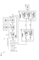
- the inspection apparatus 10 shown in FIG. 3 includes an imaging device 11 that captures an image of the article 12, and an inspection processing unit 70 that inspects the quality of the article 12 based on the imaging result captured by the imaging device 11.
- the inspection apparatus 10 may include a display unit 52 that displays inspection results of the inspection processing unit 70 and the like.
- the imaging device 11 includes M imaging units 15 (only one is shown in FIG. 3) that images the article 12 transported by the transport device 13 at the imaging position SP.
- the imaging unit 15 includes a first light source 21, a second light source 22, and a third light source 25 that irradiate the article 12 at the imaging position SP with light, and two cameras 30 (31, 32).
- the imaging device 11 includes a control processor 50 electrically connected to the light sources 21, 22, 25 and the two cameras 30 (31, 32). Note that (M-1) sets of light sources 23 and 24 and 2 (M-1) cameras 33 and 34 (whichever is 1) is electrically connected to the control processing unit 50 in the same manner as the one imaging unit 15 shown in FIG.
- the control processing unit 50 includes a control unit 51 that controls 2M light sources 21 to 24, one light source 25, and 2M cameras 30, a conversion unit 60 that processes imaging signals S1 output by the 2M cameras 30, and and a signal processing unit 65 .
- the control unit 51 may control the conveying device 13 .
- the control unit 51 controls the 2M light sources 21 to 24, one light source 25, and the 2M cameras 30 based on detection signals from the sensor 18 that detects the article 12 that has reached the imaging position SP. do.
- the control unit 51 causes the first light source 21 and the second light source 22 to emit light at different light emission timings, and causes the first camera 31 to capture the first image Img1 and the second camera 32 to capture the second image Img2.
- the imaging is performed at different imaging timings according to the light emission timings.
- the camera 30 has an optical bandpass filter 35 arranged outside the lens barrel 30a, a lens 36 arranged inside the lens barrel 30a, and a color image of light passing through the lens 36. and a color image sensor 37 for imaging.
- the camera 30 receives the transmitted light TL transmitted through the article 12 and the reflected light RL reflected by the surface of the article 12 through an optical bandpass filter 35 .
- the incident light is imaged on the color image sensor 37 through the lens 36 .
- the images include a first image Img1 and a third image Img3 (see FIGS. 5 and 6) or a second image Img2 and a fourth image Img4 (see FIGS. 7 and 8).
- the camera 30 outputs an imaging signal S1 including an image picked up by the color image sensor 37 . A detailed configuration of the camera 30 will be described later.
- the conversion unit 60 performs conversion processing to convert the imaging signal S1 input from the camera 30 into an imaging signal S2 having a relative sensitivity equal to or greater than a predetermined value in a wavelength region different from that of the imaging signal S1.
- the signal processing unit 65 performs signal processing on the imaging signal S2 to convert the imaging signal S2 into a first image signal IS1 including the first image Img1 and a second image signal IS2 including the third image Img3. Perform separation processing to separate.
- the inspection processing section 70 inspects the quality of the article 12 based on the two image signals IS1 and IS2 input from the signal processing section 65 . Then, the conversion unit 60, the signal processing unit 65, and the inspection processing unit 70 perform the above-described processing on the imaging signal S1 input from the second camera 32 as well, so that the two separated image signals IS1 and IS2 are obtained. 1/4 of the entire circumference of the article 12, for example, is inspected for quality. Then, the inspection processing unit 70 also detects the imaging signals S1 from the first camera 33 and the second camera 34, for example, from the entire circumference of the article 12 based on the separated two image signals IS1 and IS2. The pass/fail of each 1/4 region is inspected.
- the inspection processing unit 70 displays on the display unit 52 the result of the inspection of the entire circumference of the article 12 divided into a plurality of parts and the inspection image.
- the control processing unit 50 and the inspection processing unit 70 are configured by a computer, for example.
- the computer has an input device and a display section 52 .
- the display unit 52 is not limited to a monitor, and may be a display provided on an operation panel or the like. Details of the processing contents of the conversion unit 60 and the like will be described later.
- FIG. 4 is control data CD showing the control contents of the control unit 51 in the form of a table.
- "OFF" in the ON/OFF control by the control unit 51 is indicated by "-".
- the control unit 51 controls the imaging device 11 based on the control data CD shown in FIG. That is, the control unit 51 controls the first cameras 31 and 33, the second cameras 32 and 34, the first light sources 21 and 23, the second light sources 22 and 24, and the third light sources provided in the two imaging units 16 and 17. 25 respectively.
- the control unit 51 controls the imaging timings of the four cameras 31 to 34 in total.
- the control unit 51 controls the light emission timings of the first to third light sources 21-25.
- the control unit 51 captures an image of the entire circumference of the article 12 by sequentially imaging the article 12 M times (for example, four times) with the M cameras 30 . As shown in FIG. 4, when the first imaging, which is the first imaging, is performed, the control unit 51 turns on the first camera 31, the first light source 21, and the third light source 25 of the first imaging unit 16. , and all others, including the second imaging unit 17, are turned off.
- the control unit 51 turns on the second camera 32, the second light source 22, and the third light source 25 of the first imaging unit 16, and turns on the second imaging unit 17. Turn off all others including .
- the control unit 51 turns on the first camera 33, the first light source 23, and the third light source 25 of the second imaging unit 17, and turns on the first imaging unit 16. Turn off all others including .
- the control unit 51 turns on the second camera 34, the second light source 24, and the third light source 25 of the second imaging unit 17, and turns on the first imaging unit 16. Turn off all others including .
- the control unit 51 captures an image of the entire circumference of the article 12 with the four cameras 31-34.
- the four transmission images captured by the four cameras 31 to 34 are used to acquire the transmission image of the entire circumference (360 degrees) of the article 12 .
- the four reflected images captured by the four cameras 31 to 34 are used to obtain the reflected image of the entire circumference (360 degrees) of the article 12 .
- two of the cameras 31 to 34 of the imaging units 16 and 17 can simultaneously image.
- the first camera 31 and the first camera 33 can simultaneously capture images.
- 5 to 8 show ON/OFF control of the light sources 21, 22, 25 and the cameras 31, 32 when imaging is performed once.
- 5 and 6 show when the first camera 31 images the article 12
- FIGS. 7 and 8 show when the second camera 32 photographs the article 12.
- FIG. an example is shown in which the first camera 31 and the second camera 32 of the first imaging unit 16 image the article 12 at different imaging timings. Even when the first camera 33 and the second camera 34 of the second imaging unit 17 capture images of the article 12 at different imaging timings, the basic control contents are the same. 6 and 8, in order to clearly show the optical paths from the light sources 21, 22, 25 to the cameras 31, 32, the orientations of the first camera 31 and the second camera 32 are tilted from their actual horizontal orientations. It is drawn schematically in posture.
- the control unit 51 turns on the first light source 21, turns off the second light source 22, and turns on the third light source 25.
- the first light emitting portions 25a of the first light source 21 and the third light source 25 emit light as indicated by dot patterns in FIGS.
- the second light source 22 is in the off state.
- the light from the first light source 21 passes through the article 12 in the first direction D1.
- the transmitted light TL1 that has passed through the article 12 in the first direction D1 is reflected by the first half mirror 41 .
- the first half mirror 41 reflects the transmitted light TL1 (first image Img1) along the optical path to the first camera 31 .
- the second light source 22 is turned off (OFF)
- the first half mirror 41 functions as a mirror.
- Transmitted light TL1 from the first half mirror 41 passes through the optical bandpass filter 35 and enters the first camera 31 .
- the first camera 31 captures a first image Img1 of the article 12 .
- the visible light from the third light source 25 is reflected by the surface of the article 12, and the reflected light RL1 is reflected by the first half mirror 41.
- the first half mirror 41 reflects the reflected light RL ⁇ b>1 (third image Img ⁇ b>3 ) along the optical path leading to the first camera 31 .
- Reflected light RL ⁇ b>1 from first half mirror 41 passes through optical bandpass filter 35 and enters first camera 31 .
- the first camera 31 captures a third image Img3.
- the first camera 31 simultaneously captures the first image Img1, which is a near-infrared light image, and the third image Img3, which is a visible light image, in one image pickup.
- the first camera 31 outputs the imaging signal S1 to the conversion section 60 (see FIG. 3).
- the conversion unit 60 performs processing for separating the first image Img1 and the third image Img3 based on the input imaging signal S1.
- the control unit 51 turns off the first light source 21 , turns on the second light source 22 , and turns on the third light source 25 .
- the second light emitting portions 25b of the second light source 22 and the third light source 25 emit light as indicated by dot patterns in FIGS.
- the first light source 21 is in the off state.
- the light from the second light source 22 passes through the article 12 in the second direction D2.
- the transmitted light TL2 that has passed through the article 12 in the second direction D2 is reflected by the second half mirror 42 .
- the second half mirror 42 reflects the transmitted light TL2 (second image Img2) along the optical path leading to the second camera 32 .
- the second half mirror 42 functions as a mirror.
- Transmitted light TL2 from the second half mirror 42 passes through the optical bandpass filter 35 and enters the second camera 32 .
- the second camera 32 captures a second image Img2 of the article 12 .
- the visible light from the third light source 25 is reflected by the surface of the article 12, and the reflected light RL2 is reflected by the second half mirror 42.
- the second half mirror 42 reflects the reflected light RL ⁇ b>2 (fourth image Img ⁇ b>4 ) along the optical path to the second camera 32 .
- Reflected light RL ⁇ b>2 from the second half mirror 42 passes through the optical bandpass filter 35 and enters the second camera 32 .
- the second camera 32 captures a fourth image Img4.
- the second camera 32 simultaneously captures the second image Img2, which is a near-infrared light image, and the fourth image Img4, which is a visible light image, in one image pickup.
- the second camera 32 outputs the imaging signal S1 to the conversion section 60 (see FIG. 3).
- the conversion unit 60 performs processing for separating the second image Img2 and the fourth image Img4 based on the input imaging signal S1.
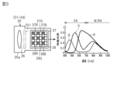
- the camera 30 shown in FIG. 9 is based on, for example, a general-purpose color camera that captures RGB images.
- a general-purpose color camera includes a lens 36 attached to a lens barrel 30a, a near-infrared light cut filter 201 (hereinafter also referred to as an IR cut filter 201) that blocks near-infrared light, and an image sensor 37. .
- the camera 30 of this embodiment is configured by removing the IR cut filter 201 indicated by the two-dot chain line in FIG. 9 from a general-purpose color camera.
- the image sensor 37 built into the camera 30 has RGB imaging characteristics including the wavelength band of near-infrared light.
- the R light receiving element 37R, the G light receiving element 37G, and the B light receiving element 37B are sensitive to light in the visible light wavelength region VA and the near infrared wavelength region NIRA shown in the graph on the right side of FIG.
- the image sensor 37 includes an R light receiving element 37R, a G light receiving element 37G and a B light receiving element 37B.
- the R light receiving element 37R receives the red light transmitted through the R filter 38R and outputs an R imaging signal corresponding to the amount of received light.
- the G light receiving element 37G receives the green light transmitted through the G filter 38G and outputs a G imaging signal corresponding to the amount of received light.
- the B light receiving element 37B receives the blue light transmitted through the B filter 38B and outputs a B imaging signal corresponding to the amount of received light.
- the R light receiving element 37R, the G light receiving element 37G and the B light receiving element 37B are arranged in a predetermined arrangement.
- the R light receiving element 37R, the G light receiving element 37G, and the B light receiving element 37B have sensitivities to light in respective wavelength bands shown in the graph on the right side of FIG.
- the horizontal axis indicates wavelength and the vertical axis indicates relative sensitivity.
- This image sensor 37 has RGB imaging characteristics that have a sensitivity equal to or higher than a predetermined value even in the wavelength band of near-infrared light. Note that the camera 30 is not limited to a configuration based on a general-purpose color camera.
- the color filters 38 of the image sensor 37 may be complementary color filters of Mg, Ye, and Cy instead of RGB primary color filters. Further, in addition to RGB filters or complementary color filters, an NIR filter that selectively transmits near-infrared light may be mixed. Further, the RGB filters may be configured by combining R, G1, G2, and B filters, and the color filter 38 may be configured by combining complementary color filters and primary color filters. Furthermore, three or more types of filters may be combined.
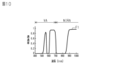
- the optical bandpass filter 35 has, for example, optical characteristics as shown in FIG.
- the optical bandpass filter 35 has spectral transmittance characteristics having one or more blocking regions in the visible light wavelength region VA and one or more transmitting regions in the near-infrared wavelength region NIRA.
- the near-infrared wavelength region NIRA is the region of wavelengths from about 800 to about 2500 nm.
- the optical band-pass filter 35 has spectral transmittance characteristics that have cutoff regions with a transmittance of 0.1 or less in a plurality of wavelength bands and transmittance regions with a transmittance of 0.7 or more in a plurality of wavelength bands. Have.
- the optical bandpass filter 35 has a spectral transmittance characteristic that has one or more blocking regions in the visible light wavelength region VA and a transmission region in the near-infrared wavelength region NIRA.
- the optical bandpass filter 35 shown in FIG. 11 is composed of one or more than two optical bandpass filters. Therefore, even if the image sensor 37 itself has relative sensitivities of three bands of RGB shown in FIG. 9, the spectral transmittance characteristics of the optical bandpass filter 35 shown in FIG. It has substantial relative sensitivities as shown in the graph.
- the R light receiving element 37R of the image sensor 37 shown in FIG. 9 has the sensitivity of the band indicated by R in the graph of the figure
- the G light receiving element 37G has the sensitivity of the band indicated by G
- the B light receiving element 37B has sensitivity in the band indicated by B.
- the light receiving elements 37R, 37G, and 37B receive the light that has passed through the filters 38R, 38G, and 38B of the color filter 38 among the light that has passed through the optical bandpass filter 35, according to their sensitivities.
- the image sensor 37 generates a first imaging signal S1 in which each imaging signal having an R value, a G value, and a B value corresponding to the amount of light received by each of the light receiving elements 37R, 37G, and 37B is serially arranged in the order of a predetermined arrangement pattern. Output.
- FIG. 12 shows the combined emission spectrum of the first light source 21 or the second light source 22, which is a near-infrared light source, and the third light source 25, which is a white light source.
- the image sensor 37 first captures the 3-band RGB signal shown in the graph of FIG. 13A as a result of synthesizing the emission intensity characteristic shown in FIG. Output as signal S1.
- the conversion unit 60 shown in FIG. 3 converts the RGB values of the first imaging signal S1 input from the image sensor 37 shown in FIG. 9 into XYZ values to generate the second imaging signal S2. That is, the conversion unit 60 converts the 3-band RGB image signal shown in the graph of FIG. 13A into a 3-band XYZ image signal (FIG. 13B) having sensitivity in a wavelength band different from that of the RGB image signal.
- the graph shown in FIG. 13B shows 3-band XYZ image signals represented by XYZ values, which constitute the second imaging signal S2.
- the horizontal axis of the graph indicates wavelength, and the vertical axis indicates relative sensitivity.
- the peak of one band of the three-band XYZ image signals forming the second imaging signal S2 is in the near-infrared wavelength region NIRA.
- the peaks of the other two bands are in the visible light wavelength region VA.
- Each band of XYZ is isolated.
- the conversion unit 60 When the imaging signal S1 is input from one of the first camera 31 and the second camera 32, the conversion unit 60 separates the imaging signal S1 into N-band RGB image signals, and converts the separated N-band RGB image signals into matrix operation. Thereby, the conversion unit 60 generates an N-band XYZ image signal.
- one band of the X image signal is in the near-infrared wavelength region NIRA, and two bands of the Y image signal and the Z image signal are in the visible light wavelength region VA.
- the conversion unit 60 converts a first image signal MS1 including a one-band X image signal having spectral sensitivity in the near-infrared region and a second image signal MS1 including a two-band YZ image signal having spectral sensitivity in the visible light region.
- the conversion unit 60 converts the first image signal MS1 of the P band (where P is a natural number less than N) having spectral sensitivity in the near-infrared region, and the Q band (where P is a natural number less than N) having spectral sensitivity in the visible light region.
- the first image Img1 and the second image Img2 are transmission images of near-infrared light.
- the third image Img3 and the fourth image Img4 are reflected images of visible light.
- the first image signal MS1 having spectral sensitivity in the near-infrared region is an image signal containing the first image Img1 or the second image Img2.
- the second image signal MS2 having spectral sensitivity in the visible light region is an image signal containing the third image Img3 or the fourth image Img4.
- the conversion unit 60 generates a first image signal MS1 including the first image Img1 and a second image signal MS2 including the third image Img3 based on the imaging signal S1 input from the first cameras 31 and 33 .
- the conversion unit 60 generates a first image signal MS1 including the second image Img2 and a second image signal MS2 including the fourth image Img4 based on the imaging signal S1 input from the second cameras 32 and 34 . In this manner, the conversion unit 60 outputs the imaging signal S2 including the P-band first image signal MS1 and the Q-band second image signal MS2.
- the first imaging signal S1 is a serial signal including an R imaging signal (red signal), a G imaging signal (green signal), and a B imaging signal (blue signal) from each of the light receiving elements 37R, 37G, and 37B. Note that the R imaging signal, the G imaging signal and the B imaging signal are also simply referred to as the R signal, the G signal and the B signal.
- the conversion section 60 includes an RGB separation section 61, an XYZ conversion section 62 and an amplification section 63.
- the RGB separation unit 61 separates the first imaging signal S1 input from the image sensor 37 into an R imaging signal, a G imaging signal, and a B imaging signal.
- the XYZ conversion section 62 converts the R, G and B signals input from the RGB separation section 61 into X, Y and Z signals. Specifically, the XYZ conversion unit 62 generates an X signal, a Y signal, and a Z signal by performing a matrix operation on RGB values, which are signal values of the R signal, the G signal, and the B signal.
- the XYZ conversion unit 62 is given matrix coefficients.
- the matrix used for matrix operation is a 3 ⁇ 3 matrix.
- a 3 ⁇ 3 matrix of coefficients is given to the XYZ transform unit 62 .
- the XYZ conversion unit 62 multiplies the RGB values of the first imaging signal S1 by a 3 ⁇ 3 matrix specified using a matrix coefficient, thereby performing a matrix operation to convert the RGB values of the first imaging signal S1 into spectral A second imaging signal S2 represented by XYZ having characteristics is generated.
- the matrix coefficients are coefficients for splitting the RGB of the first imaging signal S1 into multiple bands of XYZ of the second imaging signal S2.
- a1-a3, b1-b3, and c1-c3 are matrix coefficients, and Gx, Gy, and Gz are amplification factors.
- the XYZ conversion unit 62 performs arithmetic processing of multiplying the RGB values by a 3 ⁇ 3 matrix in the above equation (1).
- the XYZ conversion section 62 outputs to the amplification section 63 the XYZ values before being multiplied by the amplification factors.
- the number of colors of the color filter 38 in the image sensor 37 be n (where n is a natural number of 3 or more).
- a matrix operation performed between n imaging signals is an m ⁇ n matrix operation (where m is a natural number of 2 or more).
- Matrix coefficients are set in the m ⁇ n matrix so that the imaging signal for each color of the first imaging signal S1 can be separated into n bands of wavelength regions.
- Matrix coefficients are set in the 3 ⁇ 3 matrix so as to improve the separation of the three bands.
- an m ⁇ n (where m ⁇ n) matrix operation may be used.
- the number of colors is "3"
- a multispectral image with a smaller number of bands may be generated.
- the amplification unit 63 multiplies the XYZ values from the XYZ conversion unit 62 by the given X amplification factor Gx, Y amplification factor Gy, and Z amplification factor Gz.
- the amplification unit 63 multiplies the X value after XYZ conversion by the X amplification factor Gx, multiplies the Y value by the Y amplification factor Gy, and multiplies the Z value by the Z amplification factor Gz. That is, the amplifying unit 63 normalizes the XYZ bands by multiplying a 1 ⁇ 3 matrix having the amplification factors Gx, Gy, and Gz as matrix coefficients in the above equation (1).
- the amplification unit 63 outputs the normalized XYZ values as the imaging signal S2.
- the normalization process may be a method of fixing one signal level and adjusting the other two signal levels. For example, the Y signal may be fixed and the X and Z signals may be adjusted.
- the conversion unit 60 sequentially performs the RGB separation process, the XYZ conversion process, and the normalization process on the input first image signal S1, thereby outputting the second image signal S2.
- the conversion unit 60 converts the first imaging signal S1 into the second imaging signal S2.
- the first imaging signal S1 is an N-band RGB image signal.
- the second imaging signal S2 is an N-band XYZ image signal. That is, the conversion unit 60 converts the N-band RGB image signal into an N-band XYZ image signal.
- the transform unit 60 generates an N-band multispectral image.
- the XYZ image signal includes the first image signal MS1 including the X image signal of one band and the second image signal MS2 including the YZ image signal of two bands.
- the signal processing unit 65 divides the second imaging signal S2 into, for example, a first image signal MS1 of one band and a second image signal MS2 of two bands, and processes them.
- the first image signal MS1 of one band is a near-infrared image signal
- the second image signal MS2 of two bands is a visible light image signal.
- the signal processing unit 65 includes a luminance signal processing unit 66 that adjusts the luminance value of the P-band first image signal MS1 to generate the first image signal IS1, and a Q-band second image signal MS2 as a pseudo-color image signal. and a pseudo-color signal processing unit 67 for converting into a certain second image signal IS2.
- the luminance signal processing section 66 outputs the first image signal IS1 to the inspection processing section 70 .
- the pseudo-color signal processing section 67 outputs the second image signal IS2 to the inspection processing section .
- the luminance signal processing unit 66 may perform luminance adjustment by non-linear processing such as gamma correction, edge enhancement processing, and the like, if necessary.
- a first image signal IS1 shown in FIG. 14 is a transmission image signal obtained by transmitting near-infrared light through the article 12 .
- a first image based on the first image signal IS1 is displayed on the display unit 52 as a transparent image of the article 12 as shown in FIG. 15A. Therefore, it is possible to inspect the contents of the container and foreign matter mixed in the liquid in the container.
- a second image signal IS2 shown in FIG. 14 is a signal of a two-channel pseudo-color image. Therefore, the second image based on the second image signal IS2 is displayed in two-channel pseudo color on the display unit 52 (see FIG. 3). Since the inspector can see the second image on the display unit 52 and can visually recognize the defects due to the difference in color, it is easy to inspect the article 12 .
- an image based on the first image signal IS1 is also referred to as a first image IS1
- an image based on the second image signal IS2 is also referred to as a second image IS2.
- FIG. 15A shows a first image IS1, which is a near-infrared image
- FIG. 15B shows a second image IS2, which is a two-channel pseudo-color image
- the first image IS1 shown in FIG. 15A is a near-infrared transmission image of the article 12, and defects such as foreign matter mixed in the dark-colored liquid inside the container that is the article 12 are imaged relatively clearly.
- the second image IS2 shown in FIG. 15B is a visible light reflection image represented by a two-channel pseudo-color image of the article 12, and the surface of the label or the like attached to the outer peripheral surface of the article 12 is clearly imaged.
- the inspection processing unit 70 outputs a P-band first image signal IS1 having spectral sensitivity in the near-infrared region and a second Q-band image signal IS2 having spectral sensitivity in the visible light region, which are output from the imaging device 11. to inspect the article 12, which is the object.
- the inspection processing unit 70 includes a near-infrared inspection processing unit 71, a visible light inspection processing unit 72, and a mixed inspection processing unit 73.
- the first image signal IS1 is input to the near-infrared inspection processing section 71
- the second image signal IS2 is input to the visible light inspection processing section 72
- the first image signal IS1 and IS are input to the mixed inspection processing section 73.
- a second image signal IS2 is input.
- the first image signal IS1 and the second image signal IS2 input to the mixed inspection processing unit 73 are a 1-band near-infrared image signal and a 2-band visible light image signal.
- the near-infrared inspection processing unit 71 inspects the article 12 based on the first image signal IS1, which is a near-infrared image.
- the visible light inspection processing unit 72 inspects the article 12 based on the second image signal IS2, which is a visible light image.
- the mixed inspection processing unit 73 inspects the article 12 based on both the first image signal IS1 and the second image signal IS2, which are the image of the near-infrared light and the image of the visible light.
- the near-infrared inspection processing unit 71 binarizes the first image signal IS1, which is a luminance image signal, by determining the upper and lower thresholds of the luminance level, and as a result of the binarization, the size and number of the extracted inspection target areas are determined.
- the quality of the article 12 is determined based on.
- the visible light inspection processing unit 72 designates a color coordinate range from the pseudo color for the second image signal IS2, which is a pseudo color image signal, extracts a specific color area, and determines the size and number of the specific color area. 12 pass/fail judgment.
- the mixture inspection processing unit 73 obtains an AND operation result of a threshold area separately extracted from the first image signal IS1, which is a luminance image signal, and a specific color area separately extracted from the second image signal IS2, which is a false color image signal.
- the quality of the item 12 is determined based on the size and number of common areas that are used.
- the conveyor 14 of the conveying device 13 conveys an article 12 as a subject.
- the sensor 18 detects the article 12 .
- a trigger signal is input to the controller 51 .
- the controller 51 controls the light sources 21-25 and the cameras 31-34 based on the control data CD shown in FIG.
- Visible light reflected by the surface of the article 12 and near-infrared light transmitted through the article 12 pass through the optical bandpass filter 35 and the lens 36 and enter the camera 30 .
- An image of near-infrared light transmitted through the article 12 (first image Img1) and an image of visible light reflected by the surface of the article 12 (third image Img3) are captured on the imaging surface of the image sensor 37 in the camera 30. ) and are imaged.
- the image sensor 37 captures one frame of the article 12 through the optical bandpass filter 35 .
- the image sensor 37 outputs the first imaging signal S1 to the conversion section 60 .
- the first light source 21 is caused to emit light while the second light source 22 is turned off, and the first camera 31 captures the first image Img1 of the article 12 .
- This imaging process corresponds to an example of the first imaging step.
- the second light source 22 is caused to emit light while the first light source 21 is turned off, and the second camera 32 captures the second image Img2 of the article 12 .
- This imaging process corresponds to an example of the second imaging step.
- the conversion unit 60 separates the first imaging signal S1 into RGB, and multiplies the separated RGB values by a 3 ⁇ 3 matrix to convert the RGB values into XYZ values. By multiplying the XYZ values by amplification factors Gx, Gy, and Gz, normalized XYZ values are generated. In this way, the conversion unit 60 outputs the second imaging signal S2 including the 3-band multispectral image.
- the second imaging signal S2 is output to the signal processing section 65 .
- the first image signal MS1 of one band is input to the luminance signal processing unit 66, and the second image signal MS2 of two bands is input to the pseudo color signal processing unit 67.
- the first image signal MS1 is a near-infrared image signal and the second image signal MS2 is a visible light image signal.
- the luminance signal processing unit 66 adjusts the luminance value of the first image signal MS1 of one band. Also, the pseudo-color signal processing unit 67 converts the two-band second image signal MS2 into a pseudo-color image signal. As a result, the signal processing section 65 outputs the first image signal IS1 and the second image signal IS2 to the inspection processing section 70 .
- a first image IS1 including the first image Img1 is obtained based on the imaging signal S1 obtained from the first camera 31 in the first imaging step. This image acquisition process corresponds to an example of the first image acquisition step. Also, based on the imaging signal S1 obtained from the second camera 32 in the second imaging step, a second image IS2 including the second image Img2 is obtained. This image acquisition process corresponds to an example of the second image acquisition step.
- the near-infrared inspection processing unit 71 inspects the article 12 based on the first image signal IS1, which is a near-infrared image. Also, the visible light inspection processing unit 72 inspects the article 12 based on the second image signal IS2, which is a visible light image. The mixed inspection processing unit 73 inspects the article 12 based on both the first image signal IS1 and the second image signal IS2.
- Each of the inspection processing units 71 to 73 determines the quality of the article 12. If the article 12 is defective, the control unit 51 drives a discharge device (not shown) to remove the defective article 12 from the conveyor 14 .
- FIG. 15A and 15B show examples of images captured by the imaging device 11.
- the items in each image are two containers.
- the container on the left is a translucent container made of synthetic resin and contains a liquid.
- the container on the right side is a transparent glass container containing a dark-colored (for example, black) liquid.
- the first image signal IS1 is a transmission image signal obtained by transmitting near-infrared light through the article 12 .
- the display unit 52 displays the first image IS1 as a transparent image of the article 12 as shown in FIG. 15A. Therefore, it is possible to inspect the contents of the container and foreign matter mixed in the liquid in the container.
- a wire is mixed in the liquid in the container on the right side, but it is visible in the near-infrared image shown in FIG. 15A.
- the second image signal IS2 is a 2-channel pseudo-color image signal. Therefore, the display unit 52 displays the second image IS2 in two-channel pseudo-color. Since the inspector can see the second image on the display unit 52 and can visually recognize the defects due to the difference in color, it is easy to inspect the article 12 . In the visible light image of FIG. 15B, a foreign object such as a wire in the container on the right side cannot be visually recognized.
- the imaging device 11 may be configured so that the cameras 31 to 34 are not provided with the optical band-pass filters 35 and the processing (matrix calculation, etc.) for separating visible light and near-infrared light is not performed.
- the camera 30 is not limited to a color camera, and may be a monochrome camera. Even with the imaging apparatus 11 having such a configuration, it is possible to obtain an image in which defects such as foreign substances in the subject can be easily identified. An example of an image obtained by this imaging device 11 will be described with reference to FIGS. 16 and 17.
- FIG. The images shown in FIGS. 16 and 17 are images captured by a black-and-white camera having sensitivity from visible light to near-infrared light.
- a comparative example is a conventional imaging apparatus that includes four pairs of light sources and cameras that face each other with an object interposed therebetween.
- the embodiment is the imaging device 11 that does not include the optical bandpass filter 35 and does not perform separation processing (such as matrix calculation).
- FIG. 16 shows an image PI1 captured by the imaging device of the comparative example
- FIG. 17 shows an image PI2 captured by the imaging device 11 of the example.
- the article 12G which is the subject in the image, is, for example, a container.
- the background on the back side is reflected through the transparent container that is the article 12G, making it difficult to visually recognize the pattern on the surface of the container. For this reason, it is difficult to detect defects 81 such as dirt and foreign matter on the article 12G.
- the background is the first half mirror 41 located on the back side of the transparent container, which is the article 12G in the image.
- the label 82 attached to the surface of the article 12G is imaged as a reflected image, and can be visually recognized both in the image PI1 of the comparative example and the image PI2 of the example.
- the image of the label 82 in the image PI2 of the example belongs to the third image Img3 or the fourth image Img4, which are reflection images.
- the imaging device 11 includes two cameras 31 and 32 that receive light transmitted through an article 12, which is an example of a subject, from opposite directions and capture two transmitted images of the subject.
- the imaging device 11 includes a first light source 21 that emits light that passes through the article 12 in a first direction D1, and a second light source that emits light that passes through the article 12 in a second direction D2 that is opposite to the first direction.
- a second camera 32 that receives the transmitted light TL2 and captures a second image Img2 is provided.
- the imaging device 11 includes a first half mirror 41 and a second half mirror 42 .
- the first half mirror 41 reflects the first transmitted light TL1 along the optical path toward the first camera 31 at a position in the middle of the optical path of the first transmitted light TL1 while the second light source 22 is turned off. 2 Allows the transmission of the light at a position in the middle of the optical path of the light from the light source 22 toward the article 12 .
- the second half mirror 42 reflects the second transmitted light TL2 along the optical path toward the second camera 32 at a position in the middle of the optical path of the second transmitted light TL2 when the first light source 21 is turned off.
- the imaging device 11 includes a control section 51 .
- the control unit 51 causes the first light source 21 and the second light source 22 to emit light at different emission timings, thereby capturing the first image Img1 by the first camera 31 and capturing the second image Img2 by the second camera 32.
- Image pickup is performed at different image pickup timings according to light emission timings. According to this configuration, it is possible to avoid deterioration in the image quality of the captured image due to the light from the other light source.
- the imaging device 11 includes M imaging units each including the first light source 21, the second light source 22, the first camera 31, the second camera 32, the first half mirror 41, and the second half mirror 42 (where M is a natural number of 2 or more).
- the M imaging units are arranged such that the first optical axes from the article 12 to the first half mirror 41 are at different angles when the first cameras 31 of the imaging units capture images.
- the M imaging units are configured to be capable of imaging the article 12 from 2M different directions. With this configuration, the article 12 can be imaged from 2M different directions. Since 2M is 4 or more, any position on the entire circumference of the article 12 can be reliably imaged.
- the imaging device 11 further includes a third light source 25 capable of irradiating the article 12 with light.
- the first camera 31 receives the light emitted from the third light source 25 onto the article 12, which is reflected by the surface of the article 12 and reflected by the first half mirror 41, and then received by the first camera 31.
- An image Img3 is taken.
- the light emitted from the third light source 25 to the article 12 is reflected by the surface of the article 12 and reflected by the second half mirror 42, and then received by the second camera 32.
- An image Img4 is taken. According to this configuration, an image of the surface of the article 12 can be obtained in addition to an image transmitted through the article 12 .
- the first light source 21 and the second light source 22 each have a light diffusion panel 27 .
- the first half mirror 41 is adhered onto the light diffusion panel 27 of the second light source 22
- the second half mirror 42 is adhered onto the light emission diffusion panel 27 of the first light source 21 .
- the first half mirror 41 and the second half mirror 42 cannot be used as mirrors, but can be used as light sources.
- the first half mirror 41 and the second half mirror 42 can be used as mirrors.
- the light source and the half mirror can be integrated, and the shape of the light source with the half mirror function and the degree of freedom of installation can be increased.
- the first light source 21 and the second light source 22 are configured to emit near-infrared light.
- the third light source 25 is configured to emit visible light.
- the first half mirror 41 includes a visible light cut member 45 that suppresses transmission of visible light on the side of the first half mirror 41 where the second light source 22 is located.
- the second half mirror 42 includes a visible light cut member 45 that suppresses transmission of visible light on the side of the second half mirror 42 where the first light source 21 is located.
- the visible light reflected from the article 12 is reflected by the light reflecting surface of the half mirror, while the visible light cut member 45 blocks the visible light from the light source toward the half mirror. can capture a high-quality reflected image.
- the first light source 21 and the second light source 22 are configured to emit near-infrared light.
- the first camera 31 and the second camera 32 are N-band (where N is a natural number of 3 or more) color camera including an image sensor 37 having sensitivity in the visible light region and the near-infrared region.
- the imaging device 11 includes an optical bandpass filter 35 arranged on an optical path between the image sensor 37 of each of the first camera 31 and the second camera 32 and the article 12, When the imaging signal S1 is input from one of them, the imaging signal S1 is separated into N-band image signals, and matrix operation is performed on the separated N-band image signals, thereby having spectral sensitivity in the near-infrared region.
- Conversion to generate a first image signal MS1 of P-band (where P is a natural number less than N) and a second image signal MS2 of Q-band (where Q is Q NP) having spectral sensitivity in the visible light region. a portion 60;
- the conversion unit 60 converts the first image signal MS1 including the first image Img1 and the second image signal MS2 including the third image Img3 based on the imaging signal S1.
- the second camera 32 the first image signal MS1 including the second image Img2 and the second image signal MS2 including the fourth image Img4 are generated based on the imaging signal S1.
- the near-infrared transmission image and the visible light reflection image of the article 12 can be imaged in one shot, and the near-infrared transmission image of the article 12 can be obtained from one imaging signal S1 obtained by the one-time imaging. Images and visible light reflectance images can be acquired.
- the inspection device 10 includes the imaging device 11 and an inspection processing unit 70 that inspects the article 12 based on a plurality of images captured by the first camera 31 and the second camera 32 of the imaging device 11 . According to this configuration, the article 12 can be inspected with high accuracy using a plurality of transmission images obtained from light passing through the article 12 in opposite directions.
- the imaging method for imaging the article 12 using the imaging device 11 includes a first imaging step, a second imaging step, a first image acquisition step, and a second image acquisition step.
- the first image capturing step the first light source 21 is caused to emit light while the second light source 22 is turned off, and the first camera 31 captures the first image Img1 of the article 12 .
- the second image capturing step the second light source 22 is caused to emit light while the first light source 21 is turned off, and the second camera 32 captures the second image Img2 of the article 12 .
- a first image including the first image Img1 is acquired based on the imaging signal S1 acquired from the first camera 31 .
- a second image including the second image Img2 is acquired based on the imaging signal S1 acquired from the second camera 32 .
- this method similarly to the imaging device 11, two transmission images based on light transmitted through the article 12 from opposite directions can be obtained with high quality with little reflection of the periphery of the article 12. can get.
- Embodiments are not limited to the above, and may be modified as follows.
- the first camera 31 and the second camera 32 may be arranged vertically so that their respective optical axes are parallel to the vertical direction Z.
- one of the first camera 31 and the second camera 32 is arranged horizontally so that the optical axis is horizontal
- the other of the first camera 31 and the second camera 32 is arranged vertically as described above.
- the imaging unit 15 in which the camera 30 is arranged horizontally and the imaging unit 15 in which the camera 30 is arranged vertically may be mixed.
- the angle between the first optical axis and the second optical axis from the article 12 to the second half mirror 42 in the imaging by the second camera 32 may be different between the imaging units 15 .
- the entire circumference inspection of the article 12 may be performed using one imaging unit 15 . That is, the entire circumference of the article 12 is inspected based on two images (front image and back image) obtained by imaging the front and back surfaces of the article 12 with the two cameras 31 and 32 . Inspection of article 12 is not limited to a full circumference inspection. A configuration in which only a portion of the outer peripheral surface of the article 12 in the circumferential direction is inspected may be employed.
- the inspection processing unit 70 inspects the front and back sides of the article 12 based on the two images of the front and back sides of the article 12 .
- the number of cameras 30 may be three. A combination of two cameras 31 and 32 of the imaging unit 15 and a single camera 30 may be used. - In the case of a color camera having color filters of primary colors, four color filters of R, G1, G2, and B may be used. A color camera having complementary color filters may also be used, and the complementary colors may be yellow, cyan, magenta, and green.
- a 2-channel near-infrared image signal is generated based on the 2-band first image signal, and a 2-band second image signal is generated. may be used to generate a two-channel pseudo-color image signal.
- Image data (eg, RGB image data) based on the first imaging signal S1 captured by the image sensor 37 through the optical bandpass filter 35 may be stored in a removable memory such as a USB memory.
- the image data stored in the removable memory may be read by a personal computer, and the CPU (conversion unit 60) of the personal computer may perform conversion processing including matrix calculation to generate a multi-band multispectral image. That is, the device that performs the imaging step and the device that performs the conversion step may be separate devices.
- a multiband multispectral image can also be acquired by such an imaging method.
- the structure which an inspector visually recognizes and inspects the image which the imaging device 11 output may be sufficient.
- the visible light cutting member 45 may be removed from the half mirror, the visible light may be irradiated from the back of the subject, and the camera 30 may capture a transmitted image of the visible light.
- the number of colors of the color filter 38 of the image sensor 37 is not limited to three or four, but may be five or six. At least one of these colors may be a filter (NIR filter) that transmits invisible light but does not transmit visible light.
- NIR filter filter
- the article 12 which is an example of a subject to be imaged or inspected, is not particularly limited.
- the article 12 may be, for example, a container such as a PET bottle or bottle, food, beverage, electronic component, electrical appliance, daily necessities, parts, member, raw material such as powder or liquid.
- the article 12 may be, for example, an empty container or a container containing an object that is one of a liquid, a solid, and a gas having optical transparency.
- it may be a container containing a liquid.
- the article may be an ornament, a glass article, an acrylic article, an aquarium for viewing, tableware, a beaker, or an article in which a transparent or translucent container is placed in a transparent or translucent bag.
- the article may also be food such as jelly or processed food.
- the imaging device 11 may be configured as a device separate from the inspection processing unit 70 .
- the imaging device 11 may be used for purposes other than inspection.
- the arrangement pattern of the color filters 38 of the image sensor 37 is not limited to the RGB Bayer arrangement, and may be any arrangement pattern such as a stripe arrangement.
- the imaging device 11 does not need to be provided with the conveying device 13 .
- a configuration may be adopted in which an operator places the subject on, for example, a photographing table serving as an image pickup position.
- At least one of the control unit 51, the conversion unit 60, and the inspection processing unit 70 may be partially or wholly composed of software composed of a computer that executes a program, or composed of hardware such as an electronic circuit. may be
- the control processing unit 50 including the control unit 51, the conversion unit 60, and the signal processing unit 65, and the inspection processing unit 70 are not limited to having a CPU and a memory and executing software processing. That is, the control processing unit 50 and the inspection processing unit 70 may be provided with a processing circuit having any one of the following configurations (a) to (c).
- a processing circuit comprising one or more processors that perform various processes according to a computer program.
- the processor includes a CPU and memory such as RAM and ROM.
- the memory stores program code or instructions configured to cause the CPU to perform processes.
- Memory, or computer-readable media includes any available media that can be accessed by a general purpose or special purpose computer.
- processing circuitry comprising one or more dedicated hardware circuits for performing various types of processing;
- Dedicated hardware circuits may include, for example, application specific integrated circuits, or ASICs.
- a processing circuit comprising a processor that executes part of various types of processing according to a computer program, and a dedicated hardware circuit that executes the rest of the various types of processing.
- Color image sensor image sensor
- 37R...R light receiving element 37G...G light receiving element, 37B...B light receiving element
- 38...color filter as an example of spectral optical filter
- 38R...R filter 38G...G filter, 38B...B filter
- Infrared light cut filter TL1... First transmitted light, TL2... Second transmitted light, RL1... Reflected light, RL2... Reflected light, LS... Emission spectrum, S1... Third 1 imaging signal, S2... second imaging signal, MS1... first image signal, MS2... second image signal, IS1... first image signal (first image), IS2... second image signal (second image), VA ... visible light wavelength region, NIRA ... near-infrared wavelength region, D1 ... first direction, D2 ... second direction, Img1 ... first image (transmission image), Img2 ... second image (transmission image), Img3 ... Third image (reflected image), Img4... Fourth image (reflected image).
Landscapes
- Physics & Mathematics (AREA)
- General Physics & Mathematics (AREA)
- Engineering & Computer Science (AREA)
- Signal Processing (AREA)
- Multimedia (AREA)
- General Health & Medical Sciences (AREA)
- Biochemistry (AREA)
- Analytical Chemistry (AREA)
- Immunology (AREA)
- Pathology (AREA)
- Chemical & Material Sciences (AREA)
- Life Sciences & Earth Sciences (AREA)
- Health & Medical Sciences (AREA)
- Human Computer Interaction (AREA)
- Investigating Materials By The Use Of Optical Means Adapted For Particular Applications (AREA)
Abstract
L'invention concerne un dispositif d'imagerie (11) qui comprend : deux caméras (31, 32) qui capturent des images de transmission d'un article (12) à partir de directions opposées ; une première source de lumière (21) qui émet de la lumière qui est transmise à travers l'article (12) dans une première direction (D1) ; et une seconde source de lumière (22) qui émet de la lumière qui est transmise à travers l'article (12) dans une seconde direction (D2). Une première caméra (31) capture une première image qui représente l'image de transmission de l'article (12). Une seconde caméra (32) capture une seconde image qui représente l'image de transmission de l'article (12). Un premier demi-miroir (41) réfléchit la première lumière transmise vers la première caméra (31) avec la seconde source de lumière (22) éteinte, et permet la transmission de la lumière se dirigeant vers l'article (12) à partir de la seconde source de lumière (22). Un second demi-miroir (42) réfléchit la seconde lumière transmise vers la seconde caméra (32) avec la première source de lumière (21) éteinte, et permet la transmission de la lumière se dirigeant vers l'article (12) à partir de la première source de lumière (21).
Applications Claiming Priority (2)
| Application Number | Priority Date | Filing Date | Title |
|---|---|---|---|
| JP2021194975 | 2021-11-30 | ||
| JP2021-194975 | 2021-11-30 |
Publications (1)
| Publication Number | Publication Date |
|---|---|
| WO2023100805A1 true WO2023100805A1 (fr) | 2023-06-08 |
Family
ID=86612176
Family Applications (1)
| Application Number | Title | Priority Date | Filing Date |
|---|---|---|---|
| PCT/JP2022/043763 WO2023100805A1 (fr) | 2021-11-30 | 2022-11-28 | Dispositif d'imagerie, dispositif d'inspection, et procédé d'imagerie |
Country Status (2)
| Country | Link |
|---|---|
| TW (1) | TW202338335A (fr) |
| WO (1) | WO2023100805A1 (fr) |
Citations (4)
| Publication number | Priority date | Publication date | Assignee | Title |
|---|---|---|---|---|
| JP2001116700A (ja) * | 1999-08-11 | 2001-04-27 | Enutekku:Kk | 異なる波長の光を用いた物品の検査方法及び装置 |
| JP2011089978A (ja) * | 2009-08-28 | 2011-05-06 | Krones Ag | ラベル付き容器を検査するための装置と方法 |
| JP2020106504A (ja) * | 2018-12-28 | 2020-07-09 | 澁谷工業株式会社 | ラベル検査装置およびラベル検査方法 |
| JP2021145185A (ja) * | 2020-03-10 | 2021-09-24 | 株式会社エヌテック | マルチスペクトル画像撮像装置、検査装置及びマルチスペクトル画像撮像方法 |
-
2022
- 2022-11-28 WO PCT/JP2022/043763 patent/WO2023100805A1/fr unknown
- 2022-11-29 TW TW111145732A patent/TW202338335A/zh unknown
Patent Citations (4)
| Publication number | Priority date | Publication date | Assignee | Title |
|---|---|---|---|---|
| JP2001116700A (ja) * | 1999-08-11 | 2001-04-27 | Enutekku:Kk | 異なる波長の光を用いた物品の検査方法及び装置 |
| JP2011089978A (ja) * | 2009-08-28 | 2011-05-06 | Krones Ag | ラベル付き容器を検査するための装置と方法 |
| JP2020106504A (ja) * | 2018-12-28 | 2020-07-09 | 澁谷工業株式会社 | ラベル検査装置およびラベル検査方法 |
| JP2021145185A (ja) * | 2020-03-10 | 2021-09-24 | 株式会社エヌテック | マルチスペクトル画像撮像装置、検査装置及びマルチスペクトル画像撮像方法 |
Also Published As
| Publication number | Publication date |
|---|---|
| TW202338335A (zh) | 2023-10-01 |
Similar Documents
| Publication | Publication Date | Title |
|---|---|---|
| US11830179B2 (en) | Food inspection assisting system, food inspection assisting apparatus and computer program | |
| US6445452B1 (en) | Device for checking sheet packaging | |
| US8836672B2 (en) | System and method for improving machine vision in the presence of ambient light | |
| US20040150815A1 (en) | Flaw detection in objects and surfaces | |
| US20150062347A1 (en) | Image processing methods for visible and infrared imaging | |
| CN103685830B (zh) | 图像读取装置以及纸张类处理装置 | |
| JP4173184B2 (ja) | Ptp包装品の外観検査装置 | |
| JP7450917B2 (ja) | マルチスペクトル画像撮像装置、検査装置及びマルチスペクトル画像撮像方法 | |
| JP2009115613A (ja) | 異物検査装置 | |
| WO2021106964A1 (fr) | Machine de tri optique | |
| TW201215878A (en) | Imaging method for inspection of chip appearance | |
| WO2023100805A1 (fr) | Dispositif d'imagerie, dispositif d'inspection, et procédé d'imagerie | |
| KR102240757B1 (ko) | Lctf-기반 다분광 영상 기술을 이용한 가공 채소류 내 포함된 이물질 실시간 검출 시스템 | |
| JP2021190802A (ja) | 撮像装置、検査装置及び撮像方法 | |
| WO2022070774A1 (fr) | Procédé d'analyse d'image, dispositif d'analyse d'image, programme et support d'enregistrement | |
| WO2022113758A1 (fr) | Dispositif d'imagerie, dispositif d'inspection et procédé d'imagerie | |
| US11825211B2 (en) | Method of color inspection by using monochrome imaging with multiple wavelengths of light | |
| JP2016067930A (ja) | 吸収性物品の検査方法 | |
| JP7340213B1 (ja) | 透明容器の外観検査装置、外観検査システム及び外観検査方法 | |
| JPWO2022113758A5 (fr) | ||
| KR102394422B1 (ko) | Nir 스펙트럼 영상 기술을 이용한 식품 표면 이물 검사 광학장치 | |
| WO2023210619A1 (fr) | Dispositif d'imagerie, dispositif d'inspection, procédé de détermination de condition d'imagerie et procédé d'imagerie | |
| US11769246B2 (en) | Pistachio sorting device | |
| JPH09185711A (ja) | 形状認識方法及び装置 | |
| TW202409544A (zh) | 拍攝裝置、檢查裝置、拍攝條件決定方法及拍攝方法 |
Legal Events
| Date | Code | Title | Description |
|---|---|---|---|
| 121 | Ep: the epo has been informed by wipo that ep was designated in this application |
Ref document number: 22901237 Country of ref document: EP Kind code of ref document: A1 |