WO2021106063A1 - 推進制御装置および推進制御方法 - Google Patents
推進制御装置および推進制御方法 Download PDFInfo
- Publication number
- WO2021106063A1 WO2021106063A1 PCT/JP2019/046111 JP2019046111W WO2021106063A1 WO 2021106063 A1 WO2021106063 A1 WO 2021106063A1 JP 2019046111 W JP2019046111 W JP 2019046111W WO 2021106063 A1 WO2021106063 A1 WO 2021106063A1
- Authority
- WO
- WIPO (PCT)
- Prior art keywords
- wiring
- terminal
- switching element
- control device
- propulsion control
- Prior art date
- Legal status (The legal status is an assumption and is not a legal conclusion. Google has not performed a legal analysis and makes no representation as to the accuracy of the status listed.)
- Ceased
Links
Images







Classifications
-
- B—PERFORMING OPERATIONS; TRANSPORTING
- B60—VEHICLES IN GENERAL
- B60L—PROPULSION OF ELECTRICALLY-PROPELLED VEHICLES; SUPPLYING ELECTRIC POWER FOR AUXILIARY EQUIPMENT OF ELECTRICALLY-PROPELLED VEHICLES; ELECTRODYNAMIC BRAKE SYSTEMS FOR VEHICLES IN GENERAL; MAGNETIC SUSPENSION OR LEVITATION FOR VEHICLES; MONITORING OPERATING VARIABLES OF ELECTRICALLY-PROPELLED VEHICLES; ELECTRIC SAFETY DEVICES FOR ELECTRICALLY-PROPELLED VEHICLES
- B60L7/00—Electrodynamic brake systems for vehicles in general
- B60L7/02—Dynamic electric resistor braking
- B60L7/06—Dynamic electric resistor braking for vehicles propelled by AC motors
-
- B—PERFORMING OPERATIONS; TRANSPORTING
- B60—VEHICLES IN GENERAL
- B60L—PROPULSION OF ELECTRICALLY-PROPELLED VEHICLES; SUPPLYING ELECTRIC POWER FOR AUXILIARY EQUIPMENT OF ELECTRICALLY-PROPELLED VEHICLES; ELECTRODYNAMIC BRAKE SYSTEMS FOR VEHICLES IN GENERAL; MAGNETIC SUSPENSION OR LEVITATION FOR VEHICLES; MONITORING OPERATING VARIABLES OF ELECTRICALLY-PROPELLED VEHICLES; ELECTRIC SAFETY DEVICES FOR ELECTRICALLY-PROPELLED VEHICLES
- B60L7/00—Electrodynamic brake systems for vehicles in general
- B60L7/22—Dynamic electric resistor braking, combined with dynamic electric regenerative braking
-
- B—PERFORMING OPERATIONS; TRANSPORTING
- B60—VEHICLES IN GENERAL
- B60L—PROPULSION OF ELECTRICALLY-PROPELLED VEHICLES; SUPPLYING ELECTRIC POWER FOR AUXILIARY EQUIPMENT OF ELECTRICALLY-PROPELLED VEHICLES; ELECTRODYNAMIC BRAKE SYSTEMS FOR VEHICLES IN GENERAL; MAGNETIC SUSPENSION OR LEVITATION FOR VEHICLES; MONITORING OPERATING VARIABLES OF ELECTRICALLY-PROPELLED VEHICLES; ELECTRIC SAFETY DEVICES FOR ELECTRICALLY-PROPELLED VEHICLES
- B60L9/00—Electric propulsion with power supply external to the vehicle
- B60L9/16—Electric propulsion with power supply external to the vehicle using AC induction motors
- B60L9/18—Electric propulsion with power supply external to the vehicle using AC induction motors fed from DC supply lines
- B60L9/22—Electric propulsion with power supply external to the vehicle using AC induction motors fed from DC supply lines polyphase motors
-
- B—PERFORMING OPERATIONS; TRANSPORTING
- B60—VEHICLES IN GENERAL
- B60L—PROPULSION OF ELECTRICALLY-PROPELLED VEHICLES; SUPPLYING ELECTRIC POWER FOR AUXILIARY EQUIPMENT OF ELECTRICALLY-PROPELLED VEHICLES; ELECTRODYNAMIC BRAKE SYSTEMS FOR VEHICLES IN GENERAL; MAGNETIC SUSPENSION OR LEVITATION FOR VEHICLES; MONITORING OPERATING VARIABLES OF ELECTRICALLY-PROPELLED VEHICLES; ELECTRIC SAFETY DEVICES FOR ELECTRICALLY-PROPELLED VEHICLES
- B60L2200/00—Type of vehicles
- B60L2200/26—Rail vehicles
Definitions
- the present invention relates to a propulsion control device and a propulsion control method mounted on a railway vehicle.
- Patent Document 1 discloses a technique of consuming extra power that cannot be used in other trains among the power generated by the regenerative brake due to the brake resistance provided in the brake chopper circuit.
- the power supplied to the train from the overhead line includes AC power and DC power.
- DC power is supplied from the overhead line
- the line where the voltage of the overhead line is operated with a positive polarity is common, but the line where the voltage of the overhead line is operated with a negative polarity is rare.
- the polarity of the overhead wire is different, that is, when the polarity of the overhead wire is positive and negative, the electric potential applied to the train is opposite, and the current flowing through the train is opposite. Therefore, the device having the circuit configuration described in Patent Document 1 has a problem that it is difficult to deal with both the case where the polarity of the overhead wire is positive and the case where the polarity of the overhead wire is negative.
- the present invention has been made in view of the above, and an object of the present invention is to obtain a propulsion control device capable of receiving DC power from power supply lines having different voltage polarities.
- the propulsion control device of the present invention can be connected to a power line to which DC power is supplied from the power supply line or a ground line connected to a reference potential.
- the wire can be connected to the power line or ground line, and if the first wire is connected to the power line, it is connected to the ground line, and if the first wire is connected to the ground line, it is connected to the power line.
- a brake chopper in which the second wiring, the first switching element in which the first diode which is a freewheeling diode is connected in parallel, and the second switching element in which the second diode which is a freewheeling diode is connected in parallel are connected in series. It is equipped with a circuit.
- one end of the first switching element is connected to the first wiring, the other end of the first switching element and one end of the second switching element are connected at a connection point, and the second switching element is connected.
- the other end of the wiring is connected to the second wiring, and the connection point and the first wiring or the second wiring are connected via a brake resistor.
- the propulsion control device has an effect that DC power can be supplied from power supply lines having different voltage polarities.
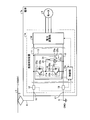
- FIG. 1 is a diagram showing a configuration example of the propulsion control device 1 according to the first embodiment of the present invention and a connection example when the propulsion control device 1 is connected to an overhead wire 2 for supplying DC power having a positive polarity voltage.
- FIG. 1 shows an example in which DC power having a voltage of + 1500 V is supplied from the overhead wire 2 to the propulsion control device 1, but the magnitude of the voltage is not limited to + 1500 V.
- the propulsion control device 1 is a device mounted on the train 7 and controls the speed of the train 7.
- the propulsion control device 1 is connected to the power line 4, the ground line 5, and the motor 6.
- DC power is supplied from the overhead wire 2 to the power line 4 via the pantograph 3. That is, DC power is supplied to the propulsion control device 1 from the overhead wire 2 via the pantograph 3 and the power line 4.
- a circuit breaker or the like is provided on the power line 4 between the pantograph 3 and the propulsion control device 1, but the description is omitted because it is a general configuration and does not affect the features of the present embodiment. doing.
- the line for supplying electric power to the train 7 is the overhead line 2, but the present invention is not limited to this, and a method of supplying electric power to the train 7 by the third rail may be used.
- the overhead wire 2 and the third rail may be collectively referred to as a power supply line.
- the ground wire 5 is connected to the reference potential.
- the reference potential is ground.
- the ground is described as "GND”. The same shall apply in the following figures.
- the propulsion control device 1 converts the DC power supplied from the power line 4 into three-phase AC power, and outputs the three-phase AC power to the motor 6.
- the motor 6 drives wheels and the like provided in the train 7 by a three-phase AC voltage output from the propulsion control device 1.
- the propulsion control device 1 includes a first wiring 11, a second wiring 12, a brake chopper circuit 13, a power conversion unit 14, a control unit 15, a terminal 16, and a terminal 17.
- the brake chopper circuit 13 includes a first switching module 20a, a second switching module 20b, and a brake resistance module 23.
- the first switching module 20a includes a first switching element 21a and a first diode 22a.
- the first diode 22a is a freewheeling diode.
- the first diode 22a is connected in parallel to the first switching element 21a.
- the first switching element 21a is, for example, an IGBT (Insulated Gate Bipolar Transistor).
- the first switching module 20a may be configured by a MOSFET (Metal Oxide Semiconductor Field Effect Transistor). Since the MOSFET has a parasitic diode, the first switching module 20a does not need to separately provide the first diode 22a by using the parasitic diode of the MOSFET as the first diode 22a.
- MOSFET Metal Oxide Semiconductor Field Effect Transistor
- the second switching module 20b includes a second switching element 21b and a second diode 22b.
- the second diode 22b is a freewheeling diode.
- the second diode 22b is connected in parallel to the second switching element 21b.
- the second switching element 21b is, for example, an IGBT.
- the second switching module 20b may be composed of MOSFETs. Since the MOSFET has a parasitic diode, the second switching module 20b does not need to separately provide the second diode 22b by using the parasitic diode of the MOSFET as the second diode 22b.
- the brake resistance module 23 includes a brake resistance 24 and a switch 25.
- the brake resistance 24 is a resistance for consuming extra power that cannot be used by other trains in the vicinity (not shown) when returning power to the overhead wire 2 when the regenerative brake is used.
- the brake resistance 24 may be a resistor having a fixed resistance value or a variable resistance whose resistance value can be changed.
- the brake resistance 24 is a variable resistance, the person in charge of the railway operator operating the train 7 can easily change the resistance value of the brake resistance 24 according to the voltage of the overhead wire 2.
- the person in charge of the railway operator is, for example, the designer of the train 7, the person in charge of maintenance of the train 7, and the like, but the person in charge is not limited thereto. In the following explanation, the person in charge of the railway operator is simply referred to as the "railway operator".
- the switch 25 is a switch that can change the connection destination of the brake resistor 24.
- the switch 25 includes a first terminal 25a, a second terminal 25b, and a third terminal 25c.
- one end of the brake resistor 24 is connected to the connection point 26, the other end of the brake resistor 24 is connected to the first terminal 25a of the switch 25, and the second terminal 25b of the switch 25 is the first. It is connected to the wiring 11, and the third terminal 25c of the switch 25 is connected to the second wiring 12.
- the switch 25 connects the first terminal 25a to the second terminal 25b or the third terminal 25c.
- the first switching module 20a and the second switching module 20b are connected in series, that is, the first switching element 21a and the second switching element 21b are connected in series.
- one end of the first switching element 21a is connected to the first wiring 11, and the other end of the first switching element 21a and one end of the second switching element 21b are connected at a connection point 26.
- the other end of the second switching element 21b is connected to the second wiring 12.
- the connection point 26 and the first wiring 11 or the second wiring 12 are connected via the brake resistance module 23, that is, the brake resistance 24 and the switch 25.
- a 2in1 package component including two IGBT elements can be used.
- the power line 4 is connected to the first wiring 11 via the terminal 16 and the ground wire 5 is connected to the second wiring 11 via the terminal 17.
- the first terminal 25a and the third terminal 25c are connected by the switch 25.
- the control unit 15 controls the operation of the brake chopper circuit 13 and the power conversion unit 14. Specifically, when the polarity of the DC power is positive, the control unit 15 always turns off the second switching element 21b and controls the chopper operation of the first switching element 21a, that is, on / off.
- the brake chopper circuit 13 when the polarity of the DC power is positive and the propulsion control device 1 is in the connected state as shown in FIG. 1, the second diode 22b of the second switching module 20b is controlled by the control unit 15. Becomes a freewheeling diode and turns on and off the first switching element 21a of the first switching module 20a.
- the brake chopper circuit 13 controls the voltage of the DC power output to the power conversion unit 14, and also controls the voltage of the DC power returned to the overhead wire 2 when the regenerative brake is used.
- the power conversion unit 14 converts the DC power output from the brake chopper circuit 13 into three-phase AC power and outputs it to the motor 6 under the control of the control unit 15. Further, when the regenerative brake is used, the power conversion unit 14 converts the three-phase AC power generated by the motor 6 into DC power and outputs it to the brake chopper circuit 13 under the control of the control unit 15.
- FIG. 2 is a diagram showing a configuration example of the propulsion control device 1 according to the first embodiment and a connection example when the propulsion control device 1 is connected to an overhead wire 2 for supplying DC power having a voltage having a negative polarity.
- FIG. 2 shows an example in which DC power having a voltage of -1500 V is supplied from the overhead wire 2 to the propulsion control device 1, but the magnitude of the voltage is not limited to -1500 V.
- the configuration of the propulsion control device 1 shown in FIG. 2 is the same as the configuration of the propulsion control device 1 shown in FIG.
- the propulsion control device 1 shown in FIG. 2 and the propulsion control device 1 shown in FIG. 1 differ in the connection destination of the power line 4, the connection destination of the ground wire 5, and the connection destination of the first terminal 25a in the switch 25.
- the power line 4 is connected to the second wiring 12 via the terminal 17, and the ground wire 5 is connected to the second wiring 12 via the terminal 16.
- the first terminal 25a and the second terminal 25b are connected to the wiring 11 of the switch 25.
- the control unit 15 controls the operation of the brake chopper circuit 13 and the power conversion unit 14. Specifically, when the polarity of the DC power is negative, the control unit 15 always turns off the first switching element 21a and controls the chopper operation of the second switching element 21b, that is, on / off.
- the brake chopper circuit 13 when the polarity of the DC power is negative and the propulsion control device 1 is in the connected state as shown in FIG. 2, the first diode 22a of the first switching module 20a is controlled by the control unit 15. Becomes a freewheeling diode and turns on and off the second switching element 21b of the second switching module 20b.
- the brake chopper circuit 13 controls the voltage of the DC power output to the power conversion unit 14, and also controls the voltage of the DC power returned to the overhead wire 2 when the regenerative brake is used.
- the first wiring 11 can be connected to the power line 4 or the ground wire 5 via the terminal 16.
- the second wire 12 can be connected to the power line 4 or the ground wire 5 via the terminal 17.
- the first wiring 11 is connected to the ground wire 5 via the terminal 16 when the second wiring 12 is connected to the power line 4 via the terminal 17, and the second wiring 12 is connected to the ground wire 5 via the terminal 17.
- the second wiring 12 is connected to the ground wire 5 via the terminal 17 when the first wiring 11 is connected to the power line 4 via the terminal 16, and the first wiring 11 connects the terminal 16.
- the terminals 16 and 17 are connectors that can be connected to, for example, one of the power line 4 and the ground line 5.
- the portion connected to the terminal 16 or the terminal 17 is a connector having a shape corresponding to the shape of the connector of the terminal 16 or the terminal 17.
- the railway operator can switch the connection destination of the power line 4, the connection destination of the ground line 5, and the connection destination of the first terminal 25a of the switch 25 depending on the line on which the train 7 is operated.
- the railway operator can use information on the polarity of the voltage of the DC power supplied from the overhead wire 2, the connection destination of the power line 4, the connection destination of the ground wire 5, and the connection destination of the first terminal 25a of the switch 25. Information is input to the control unit 15. As a result, the control unit 15 can always turn off one of the first switching element 21a and the second switching element 21b and control the on / off of the other switching element.
- the railway operator arranges that the other end of the brake resistor 24 is connected to the wiring to which the ground wire 5 is connected via the switch 25 regardless of the polarity of the DC power supplied from the overhead wire 2.
- the connection destination of the first terminal 25a of the switch 25 is switched. That is, when the polarity of the voltage of the DC power supplied from the overhead wire 2 is positive, the railway operator has the ground wire 5 connected to the second wiring 12 via the terminal 17, so that the first switch 25 is the first.
- the connection destination of the terminal 25a is set to the third terminal 25c to be connected to the second wiring 12.
- the railway operator has the ground wire 5 connected to the first wiring 11 via the terminal 16, so that the first switch 25 is the first.
- the connection destination of the terminal 25a is the second terminal 25b connected to the first wiring 11.
- the control unit 15 drives only the switching element connected to the wiring having a large absolute value of potential, and is connected to the wiring to which the absolute value of potential is small, that is, the ground wire 5 is connected. Always turn off the switching element.
- the propulsion control device 1 can connect the freewheeling diode, which is a diode connected in parallel to the switching element that is always off, to the ground, which is always the reference potential. Further, the propulsion control device 1 can connect the brake resistor 24 to the wiring to which the ground wire 5 is connected, that is, to the ground which is the reference potential, rather than the switching element which is controlled to be turned on and off.
- the brake resistor 24 if the brake resistor 24 is connected to the wiring to which the power line 4 is connected, that is, the one having the larger absolute value of the potential than the switching element controlled on / off, the brake resistor 24 is insulated. An arc may occur due to deterioration, resistor failure, etc. Therefore, in the propulsion control device 1, it is preferable to connect the brake resistor 24 to the one having the smaller absolute value of the potential, that is, the ground which is the reference potential.
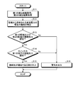
- FIG. 3 is a flowchart showing the operation of the control unit 15 included in the propulsion control device 1 according to the first embodiment.
- the control unit 15 Based on the information input by the railway operator, the control unit 15 turns on / off the first switching element 21a when the polarity of the voltage of the DC power supplied from the overhead wire 2 is positive (step S1: Yes). Control is performed so that the second switching element 21b is always turned off (step S2).
- the control unit 15 turns on / off the second switching element 21b when the polarity of the voltage of the DC power supplied from the overhead wire 2 is negative (step S1: No). Control is performed so that the first switching element 21a is always turned off (step S3).
- the brake chopper circuit 13 has the circuit configuration as described above.
- the power conversion unit 14 is a DC / AC conversion circuit having three legs in which two switching elements such as MOSFETs (not shown) are connected in series.
- the control unit 15 is realized by a processing circuit.
- the processing circuit may be a processor and memory for executing a program stored in the memory, or may be dedicated hardware.
- FIG. 4 is a diagram showing an example in which the processing circuit included in the propulsion control device 1 according to the first embodiment is configured by a processor and a memory.
- the processing circuit is composed of the processor 91 and the memory 92, each function of the processing circuit of the propulsion control device 1 is realized by software, firmware, or a combination of software and firmware.
- the software or firmware is written as a program and stored in the memory 92.
- each function is realized by the processor 91 reading and executing the program stored in the memory 92. That is, the processing circuit includes a memory 92 for storing a program in which the processing of the propulsion control device 1 is eventually executed. It can also be said that these programs cause the computer to execute the procedure and method of the propulsion control device 1.
- the processor 91 may be a CPU (Central Processing Unit), a processing device, an arithmetic unit, a microprocessor, a microcomputer, a DSP (Digital Signal Processor), or the like.
- the memory 92 includes, for example, non-volatile or volatile such as RAM (Random Access Memory), ROM (Read Only Memory), flash memory, EPROM (Erasable Programmable ROM), and EEPROM (registered trademark) (Electrically EPROM).
- RAM Random Access Memory
- ROM Read Only Memory
- flash memory e.g., EPROM (Erasable Programmable ROM), and EEPROM (registered trademark) (Electrically EPROM).
- Semiconductor memory magnetic disk, flexible disk, optical disk, compact disk, mini disk, DVD (Digital Versatile Disc), etc. are applicable.
- FIG. 5 is a diagram showing an example in which the processing circuit included in the propulsion control device 1 according to the first embodiment is configured by dedicated hardware.
- the processing circuit is composed of dedicated hardware
- the processing circuit 93 shown in FIG. 5 includes, for example, a single circuit, a composite circuit, a programmed processor, a parallel programmed processor, an ASIC (Application Specific Integrated Circuit), and the like. FPGA (Field Programmable Gate Array) or a combination of these is applicable.
- Each function of the propulsion control device 1 may be realized by the processing circuit 93 for each function, or each function may be collectively realized by the processing circuit 93.
- the functions of the propulsion control device 1 may be realized by dedicated hardware, and some may be realized by software or firmware.
- the processing circuit can realize each of the above-mentioned functions by the dedicated hardware, software, firmware, or a combination thereof.
- the connection destinations of the power line 4 and the ground line 5 are switched according to the polarity of the voltage of the DC power supplied from the overhead wire 2, and the switch is switched.
- the connection destination of the first terminal 25a of 25 it can be used even when the polarity of the voltage of the DC power supplied from the overhead wire 2 is positive or negative. That is, the propulsion control device 1 can receive DC power from overhead wires 2 having different voltage polarities.
- the propulsion control device 1 may switch the connection destination of the brake resistor 24 by two switches instead of the switch 25.
- FIG. 6 shows a first modification of the configuration of the propulsion control device 1 according to the first embodiment and a connection example when the propulsion control device 1 is connected to an overhead wire 2 for supplying DC power having a positive polarity voltage. It is a figure which shows.
- the propulsion control device 1 includes switches 27 and 28 instead of the switch 25.
- the railway operator turns on one of the switches 27 and 28 and turns off the other, depending on the route on which the train 7 is operated.
- FIG. 6 shows a case where the railway operator turns on the switch 27, turns off the switch 28, and connects the other end of the brake resistor 24 to the second wiring 12.
- the railway operator turns off the switch 27, turns on the switch 28, and connects the other end of the brake resistor 24 to the first wiring 11. Connect.
- the switches 27 and 28 may be interlocked switches so that when one is on, the other is off.
- the propulsion control device 1 may switch the connection destination of the brake resistor 24 by three or more switches in the brake chopper circuit 13. As described above, the number of switches for switching the connection destination of the brake resistor 24 may be one, or two or more, that is, a plurality of switches.
- the propulsion control device 1 may have a configuration in which the brake resistance 24 of the brake chopper circuit 13 can be externally attached.
- FIG. 7 shows a second modification of the configuration of the propulsion control device 1 according to the first embodiment and a connection example when the propulsion control device 1 is connected to an overhead wire 2 for supplying DC power having a positive polarity voltage. It is a figure which shows.
- the railway operator sets the resistance value of the brake resistance 24 for each train 7 according to the voltage of the DC power supplied from the line on which the train 7 is operated, for example, the overhead wire 2. Can be changed to.
- the brake chopper circuit 13 does not provide the switch 25, connects one end of the brake resistor 24 to the connection point 26, and directly connects the other end of the brake resistor 24 to the first wiring 11 Alternatively, it can be configured to be directly connected to the second wiring 12. Even in this case, the railway operator operating the train 7 can easily change the resistance value of the brake resistor 24 according to the voltage of the DC power supplied from the overhead wire 2.
- FIG. 7 shows a case where the other end of the brake resistor 24 is directly connected to the second wiring 12. When the polarity of the voltage of the DC power supplied from the overhead wire 2 is negative, the railway operator connects the other end of the brake resistor 24 directly to the first wiring 11.
- Embodiment 2 the railway operator sets the connection destination of the power line 4, the connection destination of the ground wire 5, and the switch 25 in the propulsion control device 1 according to the polarity of the voltage of the DC power supplied from the overhead wire 2.
- the connection destination of the first terminal 25a is switched.
- the railway operator inputs information on the polarity of the voltage of the DC power supplied from the overhead wire 2 or information on each connection destination to the control unit 15. In this case, there is a concern that the railway operator may make an input error in the control unit 15 or forget to input the input.
- the control unit determines whether or not each connection destination is appropriate for the polarity of the voltage of the DC power supplied from the overhead wire 2.
- FIG. 8 is a diagram showing a configuration example of the propulsion control device 1a according to the second embodiment and a connection example when the propulsion control device 1a is connected to an overhead wire 2 for supplying DC power having a positive polarity voltage.
- FIG. 9 is a diagram showing a configuration example of the propulsion control device 1a according to the second embodiment and a connection example when the propulsion control device 1a is connected to an overhead wire 2 for supplying DC power having a voltage having a negative polarity.
- the propulsion control device 1a is a device mounted on the train 7a to control the speed of the train 7a.
- the propulsion control device 1a is obtained by replacing the control unit 15 with the control unit 15a and adding the first sensor 18 and the second sensor 19 to the propulsion control device 1 shown in FIG.
- the first wiring 11 is connected to the power line 4 or the ground wire 5 via the terminal 16, but the connected wire connects the potential applied to the first wiring 11 and the second wiring 12.
- the potential difference from the potential is reversed, and the direction of the current flowing through the first wiring 11 is reversed. Therefore, the first sensor 18 detects at least one of the potential applied to the first wiring 11 and the current flowing through the first wiring 11. The first sensor 18 outputs the detected result to the control unit 15a as the first detection result.
- the second wiring 12 is connected to the power line 4 or the ground wire 5 via the terminal 17 as described above, but the potential applied to the second wiring 12 and the first wire are determined by the connected wires.
- the potential difference from the potential applied to the wiring 11 is reversed, and the direction of the current flowing through the second wiring 12 is reversed. Therefore, the second sensor 19 detects at least one of the potential applied to the second wiring 12 and the current flowing through the second wiring 12. The second sensor 19 outputs the detected result to the control unit 15a as the second detection result.
- the first sensor 18 detects it.
- the potential to be generated is higher than the potential detected by the second sensor 19.
- the potential detected by the second sensor 19 is a reference potential.
- the direction of the current detected by the first sensor 18 is from the outside to the inside of the propulsion control device 1a, and the direction of the current detected by the second sensor 19 is from the inside to the outside of the propulsion control device 1a.
- the ground wire 5 is connected to the first wiring 11
- the power wire 4 is connected to the second wiring 12
- the second The potential detected by the sensor 19 is higher than the potential detected by the first sensor 18.
- the potential detected by the first sensor 18 is a reference potential.
- the direction of the current detected by the second sensor 19 is from the outside to the inside of the propulsion control device 1a, and the direction of the current detected by the first sensor 18 is from the inside to the outside of the propulsion control device 1a.
- the first sensor 18 detects it.
- the potential to be generated is higher than the potential detected by the second sensor 19.
- the potential detected by the first sensor 18 is a reference potential.
- the direction of the current detected by the first sensor 18 is from the outside to the inside of the propulsion control device 1a, and the direction of the current detected by the second sensor 19 is from the inside to the outside of the propulsion control device 1a.
- the second sensor 19 is higher than the potential detected by the first sensor 18.
- the potential detected by the second sensor 19 is a reference potential.
- the direction of the current detected by the second sensor 19 is from the outside to the inside of the propulsion control device 1a, and the direction of the current detected by the first sensor 18 is from the inside to the outside of the propulsion control device 1a.
- the control unit 15a has the function of the control unit 15 as in the first embodiment, and further determines whether or not the connection destinations of the first wiring 11, the second wiring 12, and the switch 25 are appropriate. It has a function to judge. That is, the control unit 15a acquires the first detection result from the first sensor 18 and the second detection result from the second sensor 19. The control unit 15a determines the polarity of the voltage of the DC power supplied from the overhead wire 2 based on the first detection result and the second detection result. Next, the control unit 15a determines whether or not the connection destinations of the first wiring 11 and the second wiring 12 are appropriate for the polarity of the voltage of the DC power supplied from the overhead wire 2.
- control unit 15a when the polarity of the voltage of the DC power supplied from the overhead wire 2 is positive, the power line 4 is connected to the first wiring 11 and the ground wire 5 is connected to the second wiring 12. If it is, it is judged that the connection destination is appropriate. Further, in the control unit 15a, when the polarity of the voltage of the DC power supplied from the overhead wire 2 is negative, the ground wire 5 is connected to the first wiring 11 and the power line 4 is connected to the second wiring 12. When it is judged that the connection destination is appropriate.
- the control unit 15a determines whether or not the connection destination of the first terminal 25a of the switch 25 is a specified terminal based on the first detection result and the second detection result. That is, the control unit 15a monitors the connection state of the switch 25 and determines whether or not the connection destination of the first terminal 25a of the switch 25 is appropriate for the polarity of the voltage of the DC power supplied from the overhead wire 2. To do. Specifically, the control unit 15a is connected to the control unit 15a when the polarity of the DC power supplied from the overhead wire 2 is positive and the first terminal 25a of the switch 25 is connected to the third terminal 25c. Is judged to be appropriate. Further, when the polarity of the voltage of the DC power supplied from the overhead wire 2 is negative, the control unit 15a determines that the connection destination is appropriate when the first terminal 25a of the switch 25 is connected to the second terminal 25b. judge.
- the train A warning is output to at least one of the cab of 7a (not shown) and the ground device (not shown) that manages the operation of the train 7a to the effect that the connection is abnormal.
- the control unit 15a determines that the connection destination of the first wiring 11, the connection destination of the second wiring 12, and the connection destination of the first terminal 25a of the switch 25 are all appropriate, the above-mentioned cab and It may output that the connection is appropriate for at least one of the ground devices.
- FIG. 10 is a flowchart showing the operation of the control unit 15a included in the propulsion control device 1a according to the second embodiment.
- the control unit 15a acquires the first detection result from the first sensor 18 and the second detection result from the second sensor 19 (step S11).
- the control unit 15a determines the polarity of the voltage of the DC power supplied from the overhead wire 2 based on the first detection result and the second detection result (step S12).
- the control unit 15a determines whether or not the connection destinations of the first wiring 11 and the second wiring 12 are appropriate for the polarity of the voltage of the DC power supplied from the overhead wire 2 (step S13).
- step S13 determines that the connection destinations of the first wiring 11 and the second wiring 12 are appropriate (step S13: Yes)
- the switch 25 with respect to the polarity of the voltage of the DC power supplied from the overhead wire 2.
- step S14 it is determined whether or not the connection destination of the first terminal 25a is appropriate.
- step S14: Yes When the switch 25 determines that the connection destination of the first terminal 25a is appropriate (step S14: Yes), the control unit 15a outputs that the connection destination is appropriate (step S15). In the case of step S14: Yes, the control unit 15a may omit step S15 and end the operation.
- step S13: No When the control unit 15a determines that the connection destinations of the first wiring 11 and the second wiring 12 are not appropriate (step S13: No), or when the connection destination of the first terminal 25a in the switch 25 is not appropriate. If it is determined that there is no such (step S14: No), a warning is output (step S16).
- control content of the first switching element 21a and the second switching element 21b by the control unit 15a is the same as the control content by the control unit 15 described above.
- the first sensor 18 and the second sensor 19 are sensors capable of detecting at least one of the potential and the current.
- the control unit 15a is realized by a processing circuit like the control unit 15 described above.
- the processing circuit may be a processor and memory for executing a program stored in the memory, or may be dedicated hardware.
- the propulsion control device 1a is provided with the first sensor 18 after the terminal 16 of the first wiring 11 to which the power line 4 or the ground line 5 is connected, and the power line is provided.
- a second sensor 19 is provided after the terminal 17 of the second wiring 12 to which the 4 or the ground wire 5 is connected.
- the propulsion control device 1a determines the polarity of the voltage of the DC power supplied from the overhead wire 2 based on the first detection result of the first sensor 18 and the second detection result of the second sensor 19, and the overhead wire. It is determined whether or not the connection destination of the power line 4, the connection destination of the ground wire 5, and the connection destination of the first terminal 25a of the switch 25 are appropriate for the polarity of the voltage of the DC power supplied from 2. did.
- the propulsion control device 1a can obtain the same effect as that of the first embodiment, and can detect the erroneous connection of the power line 4, the ground line 5, and the first terminal 25a of the switch 25.
- the control unit 15a of the propulsion control device 1a has the first wiring 11 and the first wiring 11 based on the first detection result of the first sensor 18 and the second detection result of the second sensor 19. It was determined whether or not the connection destination of the wiring 12 of 2 was appropriate, and it was also determined whether or not the connection destination of the first terminal 25a of the switch 25 was appropriate.
- the control unit 15a controls the connection destination of the first terminal 25a of the switch 25 based on the polarity of the voltage of the DC power supplied from the overhead wire 2.
- the configuration of the propulsion control device 1a is the same as the configuration of the second embodiment shown in FIGS. 8 and 9.
- the control unit 15a connects the first terminal 25a of the switch 25 to the second terminal 25b or the third terminal 25c based on the first detection result and the second detection result. To do. That is, the control unit 15a sets the connection destination of the first terminal 25a of the switch 25 to the second terminal 25b or the third terminal 25c based on the polarity of the voltage of the DC power supplied from the overhead wire 2. Specifically, the control unit 15a connects the first terminal 25a of the switch 25 to the third terminal 25c when the polarity of the voltage of the DC power supplied from the overhead wire 2 is positive. Further, when the polarity of the voltage of the DC power supplied from the overhead wire 2 is negative, the control unit 15a connects the first terminal 25a of the switch 25 to the second terminal 25b.
- FIG. 11 is a flowchart showing the operation of the control unit 15a included in the propulsion control device 1a according to the third embodiment.
- the operation contents of steps S21 to S23 and steps S25 to S26 are described in steps S11 to S13 and steps S15 to S16 of the flowchart according to the second embodiment shown in FIG. It is the same as the operation content.
- the control unit 15a determines that the connection destinations of the first wiring 11 and the second wiring 12 are appropriate (step S23: Yes)
- the switch 25 is based on the polarity of the voltage of the DC power supplied from the overhead wire 2.
- the connection destination of the first terminal 25a of the above is controlled (step S24).
- the control unit 15a connects the first terminal 25a of the switch 25 to the third terminal 25c and is supplied from the overhead wire 2.
- the first terminal 25a of the switch 25 is connected to the second terminal 25b.
- the propulsion control device 1a is provided with the first sensor 18 after the terminal 16 of the first wiring 11 to which the power line 4 or the ground wire 5 is connected, and the power line is provided.
- a second sensor 19 is provided after the terminal 17 of the second wiring 12 to which the 4 or the ground wire 5 is connected.
- the propulsion control device 1a determines the polarity of the voltage of the DC power supplied from the overhead wire 2 based on the first detection result of the first sensor 18 and the second detection result of the second sensor 19, and the overhead wire. It was decided to control the connection destination of the first terminal 25a of the switch 25 based on the polarity of the voltage of the DC power supplied from 2.
- the propulsion control device 1a can obtain the same effect as that of the first embodiment and can detect the erroneous connection of the power line 4 and the ground line 5. Further, the propulsion control device 1a can prevent erroneous connection of the first terminal 25a of the switch 25 by automatically controlling the connection destination of the first terminal 25a of the switch 25.
- the configuration shown in the above-described embodiment shows an example of the content of the present invention, can be combined with another known technique, and is one of the configurations without departing from the gist of the present invention. It is also possible to omit or change the part.
- 1,1a propulsion control device 2 overhead wire, 3 pantograph, 4 power line, 5 ground line, 6 motor, 7,7a train, 11 1st wiring, 12 2nd wiring, 13 brake chopper circuit, 14 power conversion unit, 15,15a control unit, 16,17 terminals, 18 first sensor, 19 second sensor, 20a first switching module, 20b second switching module, 21a first switching element, 21b second switching element , 22a 1st diode, 22b 2nd diode, 23 brake resistance module, 24 brake resistance, 25, 27, 28 switch, 25a 1st terminal, 25b 2nd terminal, 25c 3rd terminal, 26 connection point ..
Landscapes
- Engineering & Computer Science (AREA)
- Power Engineering (AREA)
- Transportation (AREA)
- Mechanical Engineering (AREA)
- Life Sciences & Earth Sciences (AREA)
- Sustainable Development (AREA)
- Sustainable Energy (AREA)
- Electric Propulsion And Braking For Vehicles (AREA)
Priority Applications (4)
| Application Number | Priority Date | Filing Date | Title |
|---|---|---|---|
| PCT/JP2019/046111 WO2021106063A1 (ja) | 2019-11-26 | 2019-11-26 | 推進制御装置および推進制御方法 |
| DE112019007913.1T DE112019007913T5 (de) | 2019-11-26 | 2019-11-26 | Antriebssteuervorrichtung und antriebssteuerverfahren |
| JP2021560793A JP7106018B2 (ja) | 2019-11-26 | 2019-11-26 | 推進制御装置および推進制御方法 |
| US17/769,359 US12233751B2 (en) | 2019-11-26 | 2019-11-26 | Propulsion control device and propulsion control method |
Applications Claiming Priority (1)
| Application Number | Priority Date | Filing Date | Title |
|---|---|---|---|
| PCT/JP2019/046111 WO2021106063A1 (ja) | 2019-11-26 | 2019-11-26 | 推進制御装置および推進制御方法 |
Publications (1)
| Publication Number | Publication Date |
|---|---|
| WO2021106063A1 true WO2021106063A1 (ja) | 2021-06-03 |
Family
ID=76129249
Family Applications (1)
| Application Number | Title | Priority Date | Filing Date |
|---|---|---|---|
| PCT/JP2019/046111 Ceased WO2021106063A1 (ja) | 2019-11-26 | 2019-11-26 | 推進制御装置および推進制御方法 |
Country Status (4)
| Country | Link |
|---|---|
| US (1) | US12233751B2 (https=) |
| JP (1) | JP7106018B2 (https=) |
| DE (1) | DE112019007913T5 (https=) |
| WO (1) | WO2021106063A1 (https=) |
Cited By (1)
| Publication number | Priority date | Publication date | Assignee | Title |
|---|---|---|---|---|
| WO2023286122A1 (ja) * | 2021-07-12 | 2023-01-19 | 三菱電機株式会社 | 推進制御装置及びフィルタコンデンサ電圧の制御方法 |
Citations (2)
| Publication number | Priority date | Publication date | Assignee | Title |
|---|---|---|---|---|
| JP2004312939A (ja) * | 2003-04-09 | 2004-11-04 | Mitsubishi Electric Corp | 電気車制御装置 |
| JP2019009907A (ja) * | 2017-06-26 | 2019-01-17 | 株式会社日立製作所 | 電力変換装置および電力変換装置を備えた電気車 |
Family Cites Families (5)
| Publication number | Priority date | Publication date | Assignee | Title |
|---|---|---|---|---|
| JP2007252084A (ja) * | 2006-03-15 | 2007-09-27 | Toshiba Corp | 電気車制御装置 |
| JP6306294B2 (ja) * | 2013-06-28 | 2018-04-04 | 東洋電機製造株式会社 | 回生ブレーキ装置 |
| WO2016030941A1 (ja) * | 2014-08-25 | 2016-03-03 | 三菱電機株式会社 | 電気車制御装置 |
| JP6775437B2 (ja) | 2017-02-03 | 2020-10-28 | 東洋電機製造株式会社 | 電力変換装置 |
| RU2741318C1 (ru) * | 2018-01-26 | 2021-01-25 | Хитачи, Лтд. | Устройство преобразования мощности и электрическое железнодрожное транспортное средство, оборудованное устройством преобразования мощности |
-
2019
- 2019-11-26 DE DE112019007913.1T patent/DE112019007913T5/de active Pending
- 2019-11-26 JP JP2021560793A patent/JP7106018B2/ja active Active
- 2019-11-26 US US17/769,359 patent/US12233751B2/en active Active
- 2019-11-26 WO PCT/JP2019/046111 patent/WO2021106063A1/ja not_active Ceased
Patent Citations (2)
| Publication number | Priority date | Publication date | Assignee | Title |
|---|---|---|---|---|
| JP2004312939A (ja) * | 2003-04-09 | 2004-11-04 | Mitsubishi Electric Corp | 電気車制御装置 |
| JP2019009907A (ja) * | 2017-06-26 | 2019-01-17 | 株式会社日立製作所 | 電力変換装置および電力変換装置を備えた電気車 |
Cited By (3)
| Publication number | Priority date | Publication date | Assignee | Title |
|---|---|---|---|---|
| WO2023286122A1 (ja) * | 2021-07-12 | 2023-01-19 | 三菱電機株式会社 | 推進制御装置及びフィルタコンデンサ電圧の制御方法 |
| JPWO2023286122A1 (https=) * | 2021-07-12 | 2023-01-19 | ||
| JP7433536B2 (ja) | 2021-07-12 | 2024-02-19 | 三菱電機株式会社 | 推進制御装置及びフィルタコンデンサ電圧の制御方法 |
Also Published As
| Publication number | Publication date |
|---|---|
| US20240140205A1 (en) | 2024-05-02 |
| DE112019007913T5 (de) | 2022-09-08 |
| JP7106018B2 (ja) | 2022-07-25 |
| JPWO2021106063A1 (https=) | 2021-06-03 |
| US12233751B2 (en) | 2025-02-25 |
Similar Documents
| Publication | Publication Date | Title |
|---|---|---|
| JP6935437B2 (ja) | 電源装置 | |
| US10343713B2 (en) | Electric power steering apparatus | |
| JP5849586B2 (ja) | 3レベル電力変換回路システム | |
| JP4757815B2 (ja) | 電動機の制御装置および車両 | |
| CN103782469B (zh) | 开关驱动电路、逆变器装置以及动力转向装置 | |
| US10003294B2 (en) | Control apparatus of rotary electric machine and electric power steering apparatus using the same | |
| US20130181639A1 (en) | Motor drive system | |
| JP2016158488A (ja) | バッテリ用の充電システムを含む車両 | |
| WO2018163559A1 (ja) | 半導体スイッチの駆動装置 | |
| JP2013119270A (ja) | 信号出力回路 | |
| WO2008001427A1 (en) | Power converter | |
| WO2021106063A1 (ja) | 推進制御装置および推進制御方法 | |
| JP5697034B2 (ja) | 車両用電源供給回路 | |
| WO2020031552A1 (ja) | 駆動回路 | |
| JP5493102B2 (ja) | 絶縁劣化検出装置 | |
| JP2019047247A (ja) | 接続ユニット及び電源システム | |
| CN113597719A (zh) | 负载驱动装置 | |
| JP4513395B2 (ja) | 電動動力源装置及び電動車両 | |
| CN111264024B (zh) | 逆变器装置及其控制电路以及马达驱动系统 | |
| JP7038924B2 (ja) | 推進制御装置および推進制御方法 | |
| JP2020198765A (ja) | モータ速度検出器及びインバータ装置 | |
| JP2017109640A (ja) | モータ制御装置 | |
| JP5724913B2 (ja) | 電力変換装置 | |
| CN114257136A (zh) | 电动机驱动系统 | |
| US12170477B2 (en) | Power conversion device |
Legal Events
| Date | Code | Title | Description |
|---|---|---|---|
| 121 | Ep: the epo has been informed by wipo that ep was designated in this application |
Ref document number: 19954371 Country of ref document: EP Kind code of ref document: A1 |
|
| ENP | Entry into the national phase |
Ref document number: 2021560793 Country of ref document: JP Kind code of ref document: A |
|
| WWE | Wipo information: entry into national phase |
Ref document number: 17769359 Country of ref document: US |
|
| 122 | Ep: pct application non-entry in european phase |
Ref document number: 19954371 Country of ref document: EP Kind code of ref document: A1 |
|
| WWG | Wipo information: grant in national office |
Ref document number: 17769359 Country of ref document: US |