WO2021100544A1 - 回路構成体 - Google Patents
回路構成体 Download PDFInfo
- Publication number
- WO2021100544A1 WO2021100544A1 PCT/JP2020/041865 JP2020041865W WO2021100544A1 WO 2021100544 A1 WO2021100544 A1 WO 2021100544A1 JP 2020041865 W JP2020041865 W JP 2020041865W WO 2021100544 A1 WO2021100544 A1 WO 2021100544A1
- Authority
- WO
- WIPO (PCT)
- Prior art keywords
- bus bar
- base member
- heat
- heat conductive
- bus bars
- Prior art date
Links
Images


Classifications
-
- H—ELECTRICITY
- H01—ELECTRIC ELEMENTS
- H01R—ELECTRICALLY-CONDUCTIVE CONNECTIONS; STRUCTURAL ASSOCIATIONS OF A PLURALITY OF MUTUALLY-INSULATED ELECTRICAL CONNECTING ELEMENTS; COUPLING DEVICES; CURRENT COLLECTORS
- H01R4/00—Electrically-conductive connections between two or more conductive members in direct contact, i.e. touching one another; Means for effecting or maintaining such contact; Electrically-conductive connections having two or more spaced connecting locations for conductors and using contact members penetrating insulation
- H01R4/28—Clamped connections, spring connections
- H01R4/30—Clamped connections, spring connections utilising a screw or nut clamping member
- H01R4/34—Conductive members located under head of screw
-
- H—ELECTRICITY
- H05—ELECTRIC TECHNIQUES NOT OTHERWISE PROVIDED FOR
- H05K—PRINTED CIRCUITS; CASINGS OR CONSTRUCTIONAL DETAILS OF ELECTRIC APPARATUS; MANUFACTURE OF ASSEMBLAGES OF ELECTRICAL COMPONENTS
- H05K7/00—Constructional details common to different types of electric apparatus
- H05K7/20—Modifications to facilitate cooling, ventilating, or heating
- H05K7/2039—Modifications to facilitate cooling, ventilating, or heating characterised by the heat transfer by conduction from the heat generating element to a dissipating body
-
- H—ELECTRICITY
- H01—ELECTRIC ELEMENTS
- H01H—ELECTRIC SWITCHES; RELAYS; SELECTORS; EMERGENCY PROTECTIVE DEVICES
- H01H50/00—Details of electromagnetic relays
- H01H50/02—Bases; Casings; Covers
- H01H50/04—Mounting complete relay or separate parts of relay on a base or inside a case
- H01H50/047—Details concerning mounting a relays
-
- H—ELECTRICITY
- H01—ELECTRIC ELEMENTS
- H01H—ELECTRIC SWITCHES; RELAYS; SELECTORS; EMERGENCY PROTECTIVE DEVICES
- H01H50/00—Details of electromagnetic relays
- H01H50/12—Ventilating; Cooling; Heating
-
- H—ELECTRICITY
- H01—ELECTRIC ELEMENTS
- H01H—ELECTRIC SWITCHES; RELAYS; SELECTORS; EMERGENCY PROTECTIVE DEVICES
- H01H50/00—Details of electromagnetic relays
- H01H50/14—Terminal arrangements
-
- H—ELECTRICITY
- H01—ELECTRIC ELEMENTS
- H01R—ELECTRICALLY-CONDUCTIVE CONNECTIONS; STRUCTURAL ASSOCIATIONS OF A PLURALITY OF MUTUALLY-INSULATED ELECTRICAL CONNECTING ELEMENTS; COUPLING DEVICES; CURRENT COLLECTORS
- H01R25/00—Coupling parts adapted for simultaneous co-operation with two or more identical counterparts, e.g. for distributing energy to two or more circuits
- H01R25/14—Rails or bus-bars constructed so that the counterparts can be connected thereto at any point along their length
- H01R25/142—Their counterparts
-
- H—ELECTRICITY
- H01—ELECTRIC ELEMENTS
- H01R—ELECTRICALLY-CONDUCTIVE CONNECTIONS; STRUCTURAL ASSOCIATIONS OF A PLURALITY OF MUTUALLY-INSULATED ELECTRICAL CONNECTING ELEMENTS; COUPLING DEVICES; CURRENT COLLECTORS
- H01R25/00—Coupling parts adapted for simultaneous co-operation with two or more identical counterparts, e.g. for distributing energy to two or more circuits
- H01R25/14—Rails or bus-bars constructed so that the counterparts can be connected thereto at any point along their length
- H01R25/145—Details, e.g. end pieces or joints
-
- H—ELECTRICITY
- H02—GENERATION; CONVERSION OR DISTRIBUTION OF ELECTRIC POWER
- H02G—INSTALLATION OF ELECTRIC CABLES OR LINES, OR OF COMBINED OPTICAL AND ELECTRIC CABLES OR LINES
- H02G3/00—Installations of electric cables or lines or protective tubing therefor in or on buildings, equivalent structures or vehicles
- H02G3/02—Details
- H02G3/08—Distribution boxes; Connection or junction boxes
- H02G3/16—Distribution boxes; Connection or junction boxes structurally associated with support for line-connecting terminals within the box
-
- H—ELECTRICITY
- H05—ELECTRIC TECHNIQUES NOT OTHERWISE PROVIDED FOR
- H05K—PRINTED CIRCUITS; CASINGS OR CONSTRUCTIONAL DETAILS OF ELECTRIC APPARATUS; MANUFACTURE OF ASSEMBLAGES OF ELECTRICAL COMPONENTS
- H05K7/00—Constructional details common to different types of electric apparatus
- H05K7/02—Arrangements of circuit components or wiring on supporting structure
- H05K7/06—Arrangements of circuit components or wiring on supporting structure on insulating boards, e.g. wiring harnesses
-
- H—ELECTRICITY
- H01—ELECTRIC ELEMENTS
- H01H—ELECTRIC SWITCHES; RELAYS; SELECTORS; EMERGENCY PROTECTIVE DEVICES
- H01H1/00—Contacts
- H01H1/62—Heating or cooling of contacts
-
- H—ELECTRICITY
- H01—ELECTRIC ELEMENTS
- H01H—ELECTRIC SWITCHES; RELAYS; SELECTORS; EMERGENCY PROTECTIVE DEVICES
- H01H9/00—Details of switching devices, not covered by groups H01H1/00 - H01H7/00
- H01H9/52—Cooling of switch parts
-
- H—ELECTRICITY
- H01—ELECTRIC ELEMENTS
- H01R—ELECTRICALLY-CONDUCTIVE CONNECTIONS; STRUCTURAL ASSOCIATIONS OF A PLURALITY OF MUTUALLY-INSULATED ELECTRICAL CONNECTING ELEMENTS; COUPLING DEVICES; CURRENT COLLECTORS
- H01R2201/00—Connectors or connections adapted for particular applications
- H01R2201/26—Connectors or connections adapted for particular applications for vehicles
Definitions
- This disclosure relates to a circuit configuration including heat generating parts.
- Patent Document 1 discloses a circuit configuration including a metal battery case that houses a relay.
- This circuit configuration includes a relay as a heat generating component, a first bus bar connected to the relay, a heat conductive member arranged between the relay and the first bus bar, and between the first bus bar and the battery case. It has a heat conductive member to be arranged. Each heat conductive member is sandwiched between the first bus bar and the relay, or the first bus bar and the battery case, so that the heat of the relay is transferred from the relay to the first bus bar and from the first bus bar to the battery case.
- the path is configured to improve the heat dissipation efficiency of the relay.
- the heat conductive member is made of a synthetic resin having elasticity in an arbitrary shape such as a sheet shape, for example, a heat radiation gap filler, a heat conductive grease, a heat conductive silicone rubber, etc., which has a higher thermal conductivity than air.
- the members By being sandwiched between the members and appropriately compressed, the members can be brought into contact with each member with a high degree of adhesion, and the heat conduction efficiency can be improved.
- the heat conductive member may be excessively compressed due to the manufacturing tolerance of each member constituting the circuit configuration and the assembly tolerance when assembling each member. When the heat conductive member is excessively compressed, a large stress acts between the members due to the repulsive force of the heat conductive member, which may cause damage to each member or the like.
- the circuit configuration of the present disclosure includes a heat-generating component, a bus bar connected to a connection portion of the heat-generating component, an insulating base member that holds the heat-generating component and the bus bar, and elasticity that makes thermal contact with the bus bar.
- the bus bar presses the heat conductive member in the direction in which the bus bar is placed on the base member, and the bus bar comes into contact with the bus bar positioning portion provided on the base member.
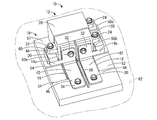
- FIG. 1 is an exploded perspective view showing a circuit configuration according to the first embodiment of the present disclosure.
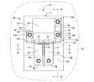
- FIG. 2 is an overall perspective view of the circuit configuration shown in FIG.
- FIG. 3 is a plan view of the circuit configuration shown in FIG.
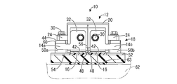
- FIG. 4 is a sectional view taken along line IV-IV in FIG.
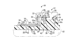
- FIG. 5 is a sectional view taken along line VV in FIG.
- FIG. 6 is an overall perspective view showing the circuit configuration according to the second embodiment of the present disclosure, and is a diagram corresponding to FIG.
- FIG. 7 is a cross-sectional view taken along the line FIG. 6 and corresponds to FIG.
- FIG. 8 is a plan view showing the circuit configuration according to the third embodiment of the present disclosure, and is a diagram corresponding to FIG.
- the circuit configuration of the present disclosure is (1) A heat-generating component, a bus bar connected to a connection portion of the heat-generating component, an insulating base member that holds the heat-generating component and the bus bar, and a heat-conducting member having elasticity that makes thermal contact with the bus bar.
- the bus bar presses the heat conductive member in the mounting direction of the bus bar on the base member, and the bus bar comes into contact with the bus bar positioning portion provided on the base member. It is a circuit configuration in which the position of the bus bar in the placement direction is defined.
- the bus bar presses the heat conductive member in the mounting direction of the bus bar on the base member, and by contacting the bus bar positioning portion provided on the base member, the bus bar in the mounting direction The position of is specified.
- the position of the bus bar in the mounting direction with respect to the base member which determines the amount of compression of the heat conductive member by the bus bar, is reliably defined by the contact of the bus bar with the bus bar positioning portion provided on the base member, and the heat conductive member is formed. It is prevented from being over-compressed by the bus bar.
- the heat conductive member may be placed on the base member and sandwiched between the base member and the bus bar, or may be thermally connected to a member outside the base member through an opening provided in the base member. May be brought into contact with the member and sandwiched between the member and the bus bar.
- the bus bar connected to the connecting portion of the heat generating component includes both a bus bar used as a conductive member and a bus bar simply used for heat dissipation.
- a fixing portion of the heat generating component is projected from the base member, the protruding end surface of the fixing portion is used as the bus bar positioning portion, and the bus bar is placed on the protruding end surface of the fixing portion to generate heat. It is preferable to have a contact portion fixed together with the component. This is because the bus bar positioning portion can be provided in a space-efficient manner by utilizing the fixing portion of the heat generating component provided on the base member. Further, since the heat-generating component and the bus bar can be fixed to the base member in a shared structure, it is possible to add a control structure for the amount of compression of the heat conductive member by the bus bar without increasing the number of components and the assembly man-hours.
- the bus bar has a first connecting portion connected to the connecting portion of the heat generating component and a second connecting portion separated from the first connecting portion and electrically connected to another member.
- the bus bar includes a pressing portion that presses the heat conductive member in an intermediate portion between the first connecting portion and the second connecting portion, and is closer to the first connecting portion side and the second connecting portion side than the pressing portion. , It is preferable that a contact portion with the bus bar positioning portion is provided. This is because the number of parts can be reduced by using the bus bar used for conducting heat to the heat-generating parts for heat dissipation.
- a pressing portion is provided in the middle portion of the bus bar for conduction, which is relatively long, and the contact portion with the bus bar positioning portion is provided on the first connection portion side and the second connection portion side with the pressing portion sandwiched between them. Since the bus bar is provided, the position of the bus bar in the mounting direction can be reliably defined on both sides of the pressing portion, and a desired compressed state of the heat conductive member can be stably realized.
- the heat conductive member is placed on the base member and sandwiched between the bus bar and the base member, and the heat is generated around the heat conductive member of the base member. It is preferable that a regulation wall is provided to regulate the deformation of the conductive member. This is because the provision of the regulating wall around the heat conductive member prevents the heat conductive member from being locally deformed and can lead the heat conductive member to a relatively uniform compressed state.
- the regulation wall is preferably provided so as to surround the entire circumference of the heat conductive member in order to realize a more uniform compressed state.
- the heat generating component is a relay
- the regulation wall is connected to the bus bar connected to the positive side connection portion of the relay and the bus bar connected to the negative side connection portion of the relay.
- the base member includes an insulating wall projecting between the two. This is because the regulation wall can be constructed by using the insulating wall provided in the base member in advance, and the number of parts can be further reduced.
- the circuit configuration 10 is attached to the skeleton of a battery pack (not shown) mounted on a vehicle such as an electric vehicle or a hybrid vehicle, and controls the electric power of the battery pack.
- the circuit configuration 10 can be arranged in any direction, but in the following description, the upper side means the upper side in FIGS. 1, 2, 4 and 5, and the lower side means the upper side in FIGS. 1, 2, 4 and 5. It shall refer to the lower part of 5.
- the front means the lower part in FIG. 3, the rear means the upper part in FIG. 3, the length direction means the vertical direction in FIG. 3, and the width direction means the left-right direction in FIG. Shall be.
- a reference numeral may be added to only a part of the members, and the reference numeral may be omitted for the other members.
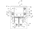
- the circuit configuration 10 includes a relay 12 which is a heat generating component, a pair of bus bars 14a and 14b, a pair of heat conductive sheets 16 and 16 constituting a heat conductive member having elasticity, and a base member. It has 18 and.
- the relay 12 is a mechanical relay, and ON / OFF control is performed by a control circuit (not shown). As shown in FIGS. 1 to 5, the relay 12 includes a block-shaped relay main body 20, a pair of annular connecting portions 22a and 22b, and a plurality of (three in the present embodiment) leg portions 24. ing.
- the relay main body 20 has a contact portion and a coil portion (not shown) inside.
- a pair of connecting portions 22a and 22b are arranged side by side in the width direction (left-right direction in FIGS. 3 and 4) on the front surface of the relay main body 20.
- the pair of connecting portions 22a and 22b generate heat by transmitting the heat generated at the contact portions by passing a current between the pair of connecting portions 22a and 22b via the contact portions of the relay main body 20.
- Each of the connecting portions 22a and 22b has a bottomed cylindrical bolt insertion hole 26 extending rearward.
- Two legs 24 are on the side surface of the relay body 20 on one side in the width direction (right side in FIG. 3), and one leg portion 24 is on the side surface of the relay body 20 on the other side in the width direction (left side in FIG. 3). It is formed so as to project in a flat plate shape toward.
- the leg portion 24 has a bolt insertion hole 28 penetrating in the vertical direction.
- a bolt 30 is inserted into the bolt insertion hole 28, and the leg portion 24 is fastened to the fixing portions 50a, 50b, and 50c projecting from the base member 18, which will be described later, so that the relay 12 is attached to the base member 18. Is fixed.
- the pair of bus bars 14a and 14b are formed by processing a metal plate material each having conductivity. As shown in FIGS. 1 and 2, each of the bus bars 14a and 14b is formed by being bent into an L shape, one end of which is the first connecting portion 32, and the other end of the bus bar 14a and 14b. It is said to be the second connection portion 34.
- the first connecting portion 32 is arranged so as to extend in the vertical direction on the front side of the connecting portions 22a and 22b of the relay 12, and has a bolt insertion hole 36 penetrating in the front-rear direction, which is the plate thickness direction.
- the bolt insertion hole 36 is a long hole that is long in the vertical direction, which is the direction in which the relay 12 and the bus bars 14a and 14b are assembled to the base member 18.
- the bus bars 14a and 14b connect the relay 12 by inserting the shaft portion 38 of the bolt 30 into the bolt insertion hole 36 of the first connection portion 32 and tightening the shaft portion 38 into the bolt insertion hole 26 of the connection portions 22a and 22b. It is electrically and thermally connected to the parts 22a and 22b.
- the second connecting portion 34 extends forward from the lower end portion of the first connecting portion 32 and has a bolt insertion hole 40 penetrating in the vertical direction, which is the plate thickness direction.
- bus bars 14a and 14b terminals of other members (not shown) are overlapped in the second connecting portion 34, bolts 30 are inserted into the bolt insertion holes 40, and bolts are fastened, so that the terminals of the second connecting portion 34 and the other members are electrically connected. Is connected.
- the bus bar 14a is connected to the positive side connecting portion 22a of the relay 12
- the bus bar 14b is connected to the negative side connecting portion 22b of the relay 12.
- the bus bars 14a and 14b include a pressing portion 42 in an intermediate portion between the first connecting portion 32 and the second connecting portion 34.
- the pressing portion 42 is formed so as to extend from the lower end portion of the first connecting portion 32 toward the front second connecting portion 34 in a rectangular flat plate shape.
- the bus bars 14a and 14b extend from the lower end of the first connecting portion 32 in a rectangular flat plate shape in a direction away from the bus bars 14a and 14b, and then project rearward in an L shape.
- the first contact portion 44 is formed by the protruding end portion of this portion.
- the first contact portion 44 is provided with a bolt insertion hole 45 that penetrates in the vertical direction, which is the plate thickness direction.
- the first contact portion 44 is placed on the protruding end faces 60 of the fixing portions 50a and 50b of the base member 18 constituting the bus bar positioning portion described later, and is fixed together with the leg portion 24 of the relay 12. That is, a first contact portion 44 that contacts the protruding end faces 60 of the fixing portions 50a and 50b constituting the bus bar positioning portion described later is provided on the first connection portion 32 side of the pressing portions 42 of the bus bars 14a and 14b. There is.
- a second contact portion 46 is provided on the second connecting portion 34 side of the pressing portions 42 of the bus bars 14a and 14b. The second contact portion 46 is placed on the side wall 54 on the front side of the heat conductive sheet accommodating portion 48 of the base member 18 constituting the bus bar positioning portion described later.
- a relay 12 a pair of bus bars 14a and 14b, and a pair of heat conductive sheets 16 and 16 are assembled from above to hold the members. It is configured.
- the base member 18 has a flat rectangular parallelepiped shape extending in the length direction as a whole, and is formed of an insulating synthetic resin.
- the base member 18 includes a pair of heat conductive sheet accommodating portions 48, 48 and three fixing portions 50a, 50b, 50c.
- the pair of heat conductive sheet accommodating portions 48, 48 extend at a constant depth dimension over the entire length in the width direction (left-right direction in FIG. 3) in the region on the front side of the central portion of the base member 18, and extend upward and upward. It is formed in a recess 52 that opens on both sides in the width direction. A pair of side walls 54, 54 are formed at both end edges of the recess 52 in the length direction. Further, at the central portion in the width direction of the recess 52, the portion extending from the rear side (upper side in FIG. 3) of the recess 52 extends toward the front side beyond the front end of the recess 52. , A flat plate-shaped insulating wall 56 is formed.
- the insulating wall 56 projects between the pair of bus bars 14a and 14b with the pair of bus bars 14a and 14b mounted on the base member 18, and projects upward from the upper surface 58 of the base member 18. It is installed.
- a pair of heat conductive sheet accommodating portions 48, 48 are formed by the recesses 52 divided by the insulating wall 56.
- the pair of heat conductive sheets 16 and 16 are arranged so as to be close to the insulating wall 56 with respect to the pair of heat conductive sheet accommodating portions 48 and 48, respectively.
- three of the four sides of the pair of heat conductive sheets 16 and 16 are surrounded by the pair of side walls 54 and 54 of the recess 52 and the insulating wall 56, respectively.
- a regulation wall that regulates the deformation of the heat conductive sheet 16 is formed by a pair of side walls 54, 54 and an insulating wall 56.
- the heat conductive sheet 16 constituting the elastic heat conductive member transfers the heat of the bus bars 14a and 14b to the base member 18.
- the heat conductive sheet 16 has a flat sheet shape in the vertical direction, and is made of a synthetic resin having elasticity having a higher thermal conductivity than air. Specifically, silicone-based resins, non-silicone-based acrylic resins, ceramic-based resins, and the like can be used. More specifically, for example, a heat dissipation gap filler, a heat conductive grease, a heat conductive silicone rubber, etc. made of a silicone resin can be mentioned.
- the heat conductive sheet 16 has flexibility and elasticity, and can be elastically deformed so that the thickness dimension changes according to the force applied in the vertical direction. In the present embodiment, the heat conductive sheet 16 is adopted as the heat conductive member, but the heat conductive member is not limited to this, and a heat conductive member having elasticity of any shape can be adopted.
- the fixing portions 50a, 50b, and 50c are arranged in a region on the rear side of the central portion of the base member 18, and the fixing portion 50a is upward in a substantially rectangular cross-sectional shape from the upper surface 57 on one side in the width direction (left side in FIG. 3).
- the fixing portions 50b and 50c are formed so as to project upward from the upper surface 57 on the other side in the width direction (right side in FIG. 3) in a substantially rectangular cross-sectional shape.
- the protruding end faces 60 of the fixing portions 50a, 50b, and 50c are provided with bottomed cylindrical bolt insertion holes 61 that open upward.
- the protruding end faces 60 of the fixing portions 50a and 50b are formed to be lower than the protruding end faces 60 of the fixing portions 50c by the thickness of the bus bars 14a and 14b.
- Bracket 62 The base member 18 of the circuit configuration 10 is assembled to a bracket 62 attached to the skeleton of a battery pack (not shown).
- a bracket 62 to which the circuit configuration 10 is attached is shown by a virtual line.
- the bracket 62 is made of a metal having thermal conductivity.
- the bottom surface of the base member 18 is fixed to the surface of the bracket 62 by a fixture (not shown) in a state where the heat conductive sheet 63 is sandwiched between them and superposed. As a result, the heat conductive sheet 63 comes into close contact with the bottom surface of the base member 18 and the surface of the bracket 62.
- the two heat conductive sheets 16 are cut out into a predetermined shape by a known method such as Thomson die cutting, and attached to a predetermined position in the pair of heat conductive sheet accommodating portions 48, 48 of the base member 18.
- a pair of bus bars 14a and 14b are placed on the base member 18 to which the heat conductive sheet 16 is attached from above in a state of being arranged so as to extend in the length direction. Further, the relay 12 is placed at a predetermined position on the base member 18. In this state, the first contact portions 44 of the pair of bus bars 14a and 14b are bolted to the protruding end faces 60 of the fixing portions 50a and 50b of the base member 18 together with the legs 24 of the relay 12 to fix the base member 18. The legs 24 of the relay 12 that remain with respect to the protruding end surface 60 of the portion 50c are bolted together.
- the first connecting portions 32 of the bus bars 14a and 14b are bolted to the connecting portions 22a and 22b of the relay 12, respectively.
- the bolt insertion hole 36 provided in the first connection portion 32 is a long hole that is long in the vertical direction
- the connection portions 22a and 22b of the relay 12 are vertically oriented with respect to the pair of bus bars 14a and 14b. Tolerances are absorbed favorably.
- the second connecting portions 34 of the pair of bus bars 14a and 14b are electrically connected to the other members by overlapping the terminals of other members (not shown) and bolting them together, so that the circuit configuration 10 Is completed.
- the pressing portion 42 of the bus bars 14a and 14b presses the heat conductive sheet 16 in the vertical direction, which is the mounting direction of the bus bars 14a and 14b on the base member 18. More specifically, the heat conductive sheet 16 is placed in the heat conductive sheet accommodating portion 48 formed in the base member 18, and is sandwiched between the bus bars 14a and 14b and the base member 18. The heat conductive sheet 16 is in thermal contact with the bus bars 14a and 14b and the base member 18, and the heat generated by the relay 12 is transferred from the connecting portions 22a and 22b to the bus bars 14a and 14b to transfer the heat to the bus bars 14a and 14b. Heat is dissipated to the base member 18 via 16.
- the first contact portion 44 of the bus bars 14a and 14b is placed on the protruding end surface 60 of the fixing portions 50a and 50b of the base member 18 and fixed together with the leg portion 24 of the relay 12, and the second contact portion 46 is mounted on the side wall 54 on the front side of the heat conductive sheet accommodating portion 48 of the base member 18. That is, the bus bars 14a and 14b come into contact with the protruding end faces 60 of the fixing portions 50a and 50b constituting the bus bar positioning portion provided on the base member 18 and the upper surface 58 of the side wall 54 on the front side of the heat conductive sheet accommodating portion 48. Thereby, the positions of the bus bars 14a and 14b in the mounting direction are defined.
- the base member 18 of the circuit configuration 10 is fixed to the surface of the bracket 62 with a heat conductive sheet 63 sandwiched between them by a fixture (not shown).
- a fixture not shown
- the heat of the relay 12 transferred to the base member 18 via the bus bars 14a and 14b and the heat conductive sheet 16 is transferred to the bracket 62 and the skeleton of the battery pack via the heat conductive sheet 63.
- the path is configured so that the heat dissipation of the relay 12 can be efficiently achieved.
- the pressing portions 42 of the bus bars 14a and 14b press the heat conductive sheet 16 in the vertical direction.
- the bus bars 14a and 14b come into contact with the protruding end faces 60 of the fixing portions 50a and 50b constituting the bus bar positioning portion provided on the base member 18 and the upper surface 58 of the side wall 54 on the front side of the heat conductive sheet accommodating portion 48.
- the positions of the bus bars 14a and 14b in the mounting direction are defined.
- the position of the bus bars 14a, 14b in the mounting direction with respect to the base member 18 that determines the amount of compression of the heat conductive sheet 16 by the bus bars 14a, 14b is the protruding end surface 60 of the fixing portions 50a, 50b provided on the base member 18. And is securely defined by the upper surface 58 of the side wall 54 on the front side of the heat conductive sheet accommodating portion 48. This prevents the heat conductive sheet 16 from being excessively compressed by the bus bars 14a and 14b. Further, since the bus bar positioning portion is composed of the base member 18 on which the bus bars 14a and 14b are directly mounted, it is also advantageous that the heat conductive sheet 16 is excessively compressed due to the overlapping tolerances of many members. It has been resolved.
- the bus bar positioning portion is formed by using the existing fixing portions 50a and 50b for the relay 12 provided on the base member 18, the space does not increase in the number of parts and the assembly man-hours.
- the bus bar positioning portion can be efficiently formed.
- bus bars 14a and 14b which are conductive members for energizing the relay 12 with other members, are used for heat dissipation, the number of parts is reduced.
- a pressing portion 42 is provided at an intermediate portion between the relatively long bus bars 14a and 14b for conduction, and a base member is provided on the first connecting portion 32 side and the second connecting portion 34 side with the pressing portion 42 sandwiched between them.
- a first contact portion 44 and a second contact portion 46 that come into contact with the bus bar positioning portion 18 (in this embodiment, the upper surface 58 and the protruding end surface 60) are provided.
- the bus bars 14a and 14b can be reliably brought into contact with the bus bar positioning portions on both sides of the pressing portion 42, and a desired compressed state of the heat conductive sheet 16 can be stably realized.
- the deformation of the heat conductive sheet 16 is regulated by the pair of side walls 54, 54 and the insulating wall 56 of the base member 18 surrounding the heat conductive sheets 16, 16, so that the heat conductive sheet 16 is locally deformed. Can be prevented and the heat conductive sheet 16 can be brought into a relatively uniform compressed state. Moreover, since the insulating wall 56 previously provided on the base member 18 is used, the number of parts is further reduced.
- the heat generated by the relay 12 is transferred from the connecting portions 22a and 22b to the bus bars 14a and 14b, transferred to the base member 18 via the heat conductive sheet 16, and heat is transferred from the base member 18.
- a heat transfer path is configured in which heat is transferred to the bracket 62 via the conduction sheet 63, but the present invention is not limited to this.
- the bus bars 14a and 14b may be in thermal contact.
- the heat conductive member having elasticity, heat dissipation gap filler, heat conductive grease or the like may be adopted in place of or in addition to the heat conductive sheets 16 and 63.
- bus bars 14a and 14b are in direct thermal contact with the heat conductive sheet 16, but the present invention is not limited to this, and the bus bars 14a and 14b are heated via other members. It may be in thermal contact with the conductive sheet 16.
- bus bars 14a and 14b are used as conductive members, but the present invention is not limited to this, and the bus bar is simply used for heat dissipation as long as it is connected to the connection portion of the heat generating component. It may be the one that can be used.
- the contact portions 44 and 46 of the bus bars 14a and 14b are attached to the protruding end faces 60 of the fixing portions 50a and 50b for the relay 12 provided on the base member 18 which is the bus bar positioning portion. It was placed directly, but it is not limited to this.
- the contact portions 44 of the bus bars 14a and 14b are attached to the protruding end faces 60 of the fixing portions 50a and 50b via the legs 24 of the relay 12. 46 may be placed.
- the thin legs 24 are merely interposed, the overlap of the tolerances of a large number of members is restricted as in the first embodiment, and the heat conductive sheet 16 is the bus bar 14a. It is prevented from being excessively compressed by 14b.
- a regulating projection 65 for preventing excessive deformation of the heat conductive sheet 63 is provided, and the heat conductive sheet 63 is provided between the base member 18 and the bracket 62. Excessive compression may be suppressed.
- the circuit configuration 10 of the present disclosure three of the four sides of the pair of heat conductive sheets 16 and 16 are surrounded by the pair of side walls 54 and 54 of the recess 52 and the insulating wall 56, respectively. , Not limited to this.
- the four sides of the pair of heat conductive sheets 16 and 16 have the pair of side walls 54 and 54 of the recess 52, the insulating wall 56 and the regulating wall 68, respectively. It may be surrounded by.
- the regulation wall 68 is projected so as to have a height dimension equal to or greater than the depth dimension of the recess 52 over the entire length of the recess 52 in the length direction.
- Circuit configuration (Embodiment 1) 12 Relays (heat generating parts) 14a Bus bar 14b Bus bar 16 Heat conduction sheet (heat conduction member) 18 Base member 20 Relay body 22a Connection part 22b Connection part 24 Leg part 26 Bolt insertion hole 28 Bolt insertion hole 30 Bolt 32 First connection part 34 Second connection part 36 Bolt insertion hole 38 Shaft part 40 Bolt insertion hole 42 Pressing part 44 First contact part 45 Bolt insertion hole 46 Second contact part 48 Heat conduction sheet accommodating part 50a Fixing part 50b Fixing part 50c Fixing part 52 Recession 54 Side wall (regulatory wall) 56 Insulated wall (regulatory wall) 57 Top surface 58 Top surface 60 Protruding end surface 61 Bolt insertion hole 62 Bracket 63 Heat conduction sheet (heat conduction member) 64 Circuit Configuration (Embodiment 2) 65 Regulatory protrusion 66 Circuit configuration (Embodiment 3) 68 Regulatory wall
Landscapes
- Physics & Mathematics (AREA)
- Electromagnetism (AREA)
- Engineering & Computer Science (AREA)
- Microelectronics & Electronic Packaging (AREA)
- Thermal Sciences (AREA)
- Architecture (AREA)
- Civil Engineering (AREA)
- Structural Engineering (AREA)
- Connection Or Junction Boxes (AREA)
- Cooling Or The Like Of Electrical Apparatus (AREA)
Abstract
熱伝導部材の反発力を制御して、熱伝導部材の過剰な反発力による不具合の発生を未然に防止することができる新規な構造の回路構成体を提供する。 発熱部品12と、発熱部品12の接続部22a,22bに接続されたバスバー14a,14bと、発熱部品12とバスバー14a,14bを保持する絶縁性のベース部材18と、バスバー14a,14bと熱的に接触する弾性を有する熱伝導部材16とを備え、バスバー14a,14bのベース部材18への載置方向でバスバー14a,14bが熱伝導部材16を押圧し、ベース部材18に設けられたバスバー位置決め部54,60に対してバスバー14a,14bが当接することにより、載置方向におけるバスバー14a,14bの位置が規定される回路構成体10である。
Description
本開示は、発熱部品を含む回路構成体に関する。
従来から、車両には、リレー等の発熱部品を含む回路構成体が搭載されている。例えば、特許文献1には、リレーを収容する金属製のバッテリケースを備えた回路構成体が開示されている。この回路構成体は、発熱部品としてのリレーと、リレーに接続される第1バスバーと、リレーと第1バスバーとの間に配置される熱伝導部材と、第1バスバーとバッテリケースとの間に配置される熱伝導部材とを備えている。それぞれの熱伝導部材は、第1バスバーとリレー、または、第1バスバーとバッテリケースに挟まれることにより、リレーから第1バスバー、第1バスバーからバッテリケースへとリレーの熱が伝達される伝熱経路を構成し、リレーの放熱効率を向上させるようになっている。
ところで、熱伝導部材は、シート状等の任意の形状で弾性を有する、例えば放熱ギャップフィラーや熱伝導グリースや熱伝導性シリコーンゴム等の空気よりも熱伝導率の大きな合成樹脂からなり、部材間に挟まれて適度に圧縮されることによって各部材に対して高い密着度で接触し、熱伝導効率を高めることができる。しかしながら、回路構成体を構成する各部材の製造公差や各部材を組み付ける際の組付公差によって熱伝導部材が過剰に圧縮される場合がある。熱伝導部材が過剰に圧縮された場合には、熱伝導部材の反発力によって、各部材間に大きな応力が作用し、各部材等の損傷を招くおそれがあった。
そこで、熱伝導部材の反発力を制御して、熱伝導部材の過剰な反発力による不具合の発生を未然に防止することができる新規な構造の回路構成体を開示する。
本開示の回路構成体は、発熱部品と、前記発熱部品の接続部に接続されたバスバーと、前記発熱部品と前記バスバーを保持する絶縁性のベース部材と、前記バスバーと熱的に接触する弾性を有する熱伝導部材とを備え、前記バスバーの前記ベース部材への載置方向で前記バスバーが前記熱伝導部材を押圧し、前記ベース部材に設けられたバスバー位置決め部に対して前記バスバーが当接することにより、前記載置方向における前記バスバーの位置が規定される回路構成体である。
本開示によれば、熱伝導部材の反発力を制御して、熱伝導部材の過剰な反発力による不具合の発生を未然に防止することができる。
<本開示の実施形態の説明>
最初に、本開示の実施態様を列記して説明する。
本開示の回路構成体は、
(1)発熱部品と、前記発熱部品の接続部に接続されたバスバーと、前記発熱部品と前記バスバーを保持する絶縁性のベース部材と、前記バスバーと熱的に接触する弾性を有する熱伝導部材とを備え、前記バスバーの前記ベース部材への載置方向で前記バスバーが前記熱伝導部材を押圧し、前記ベース部材に設けられたバスバー位置決め部に対して前記バスバーが当接することにより、前記載置方向における前記バスバーの位置が規定される回路構成体である。
最初に、本開示の実施態様を列記して説明する。
本開示の回路構成体は、
(1)発熱部品と、前記発熱部品の接続部に接続されたバスバーと、前記発熱部品と前記バスバーを保持する絶縁性のベース部材と、前記バスバーと熱的に接触する弾性を有する熱伝導部材とを備え、前記バスバーの前記ベース部材への載置方向で前記バスバーが前記熱伝導部材を押圧し、前記ベース部材に設けられたバスバー位置決め部に対して前記バスバーが当接することにより、前記載置方向における前記バスバーの位置が規定される回路構成体である。
本開示によれば、バスバーのベース部材への載置方向でバスバーが熱伝導部材を押圧するようになっており、ベース部材に設けられたバスバー位置決め部に当接することにより、載置方向におけるバスバーの位置が規定されるようになっている。これにより、バスバーによる熱伝導部材の圧縮量を決定するベース部材に対するバスバーの載置方向の位置が、ベース部材に設けられたバスバー位置決め部に対するバスバーの当接により確実に規定され、熱伝導部材がバスバーにより過剰に圧縮されることが未然に防止されている。また、ベース部材に対するバスバーの載置方向の位置が、バスバー位置決め部とバスバーの当接により規定されていることから、多数の部材の公差が重なり合うことにより熱伝導部材の過剰圧縮が生じる不具合も解消されている。その結果、熱伝導部材を所望の圧縮率で圧縮させて優れた放熱性を実現することが、安定して実現され得る。
なお、熱伝導部材は、ベース部材に載置されてベース部材とバスバーの間で挟持されるようにしてもよいし、ベース部材に設けられた開口部を介してベース部材外の部材に熱的に接触して、当該部材とバスバーの間で挟持されるようにしてもよい。
バスバーは、発熱部品の接続部に接続されているため、発熱部品の熱が有利に伝熱される。発熱部品の接続部に接続されたバスバーは、導通部材として用いられるものも、単に放熱用に用いられるものもいずれも含まれる。
(2)前記ベース部材に前記発熱部品の固定部が突設されており、前記固定部の突出端面が前記バスバー位置決め部とされ、前記バスバーが前記固定部の突出端面に載置されて前記発熱部品と共に固定される当接部を有していることが好ましい。ベース部材に設けられた発熱部品の固定部を利用して、スペース効率よくバスバー位置決め部を設けることができるからである。また、発熱部品とバスバーのベース部材への固定構造を共有化できることから、部品点数や組付工数の増加を伴うことなく、バスバーによる熱伝導部材の圧縮量の制御構造を付加することができる。
(3)前記バスバーが、前記発熱部品の前記接続部に接続される第一接続部と、該第一接続部から離隔して他部材に導通接続される第二接続部を有しており、前記バスバーが、前記第一接続部と前記第二接続部の中間部分に前記熱伝導部材を押圧する押圧部を含み、該押圧部よりも前記第一接続部側と前記第二接続部側に、前記バスバー位置決め部への当接部が設けられていることが好ましい。発熱部品への導通用として用いられるバスバーを放熱用として利用することで、部品点数の削減が図られるからである。しかも、比較的長尺となる導通用のバスバーの中間部分に押圧部が設けられ押圧部を間に挟んだ第一接続部側と第二接続部側で、バスバー位置決め部への当接部が設けられていることから、バスバーの載置方向における位置を押圧部の両側で確実に規定することができ、所望の熱伝導部材の圧縮状態を安定して実現できる。
(4)前記熱伝導部材が、前記ベース部材に載置されて前記バスバーと前記ベース部材の間で挟持されるようになっており、前記ベース部材の前記熱伝導部材の周囲には、前記熱伝導部材の変形を規制する規制壁が設けられていることが好ましい。熱伝導部材の周囲に規制壁が設けられることにより、熱伝導部材の局所的な変形が防止され、熱伝導部材を比較的均一な圧縮状態に導くことができるからである。なお、規制壁は、より均一な圧縮状態を実現するために、好ましくは熱伝導部材の全周を囲って設けられる。
(5)上記(4)において、前記発熱部品がリレーであり、前記規制壁が、前記リレーのプラス側接続部に接続される前記バスバーと、前記リレーのマイナス側接続部に接続される前記バスバーの間において前記ベース部材に突設された絶縁壁を含んで構成されていることが好ましい。予めベース部材に設けられていた絶縁壁を利用して規制壁を構成でき、部品点数の更なる削減を図ることができるからである。
<本開示の実施形態の詳細>
本開示の回路構成体の具体例を、以下に図面を参照しつつ説明する。なお、本開示は、これらの例示に限定されるものではなく、特許請求の範囲によって示され、特許請求の範囲と均等の意味および範囲内でのすべての変更が含まれることが意図される。
本開示の回路構成体の具体例を、以下に図面を参照しつつ説明する。なお、本開示は、これらの例示に限定されるものではなく、特許請求の範囲によって示され、特許請求の範囲と均等の意味および範囲内でのすべての変更が含まれることが意図される。
<実施形態1>
以下、本開示の実施形態1について、図1から図5を参照しつつ説明する。回路構成体10は、例えば電気自動車やハイブリッド自動車等の車両に搭載される図示しない電池パックの骨格に取り付けられ、電池パックの電力を制御する。回路構成体10は、任意の向きで配置することができるが、以下の説明においては、上方とは、図1,2,4,5中の上方、下方とは、図1,2,4,5中の下方を言うものとする。また、前方とは、図3中の下方、後方とは、図3中の上方を言い、長さ方向とは、図3中の上下方向、幅方向とは、図3中の左右方向を言うものとする。さらに、複数の同一部材については、一部の部材にのみ符号を付し、他の部材については符号を省略する場合がある。
以下、本開示の実施形態1について、図1から図5を参照しつつ説明する。回路構成体10は、例えば電気自動車やハイブリッド自動車等の車両に搭載される図示しない電池パックの骨格に取り付けられ、電池パックの電力を制御する。回路構成体10は、任意の向きで配置することができるが、以下の説明においては、上方とは、図1,2,4,5中の上方、下方とは、図1,2,4,5中の下方を言うものとする。また、前方とは、図3中の下方、後方とは、図3中の上方を言い、長さ方向とは、図3中の上下方向、幅方向とは、図3中の左右方向を言うものとする。さらに、複数の同一部材については、一部の部材にのみ符号を付し、他の部材については符号を省略する場合がある。
<回路構成体10>
回路構成体10は、図1に示すように、発熱部品であるリレー12と、一対のバスバー14a,14bと、一対の弾性を有する熱伝導部材を構成する熱伝導シート16,16と、ベース部材18とを備えている。
回路構成体10は、図1に示すように、発熱部品であるリレー12と、一対のバスバー14a,14bと、一対の弾性を有する熱伝導部材を構成する熱伝導シート16,16と、ベース部材18とを備えている。
<リレー12>
リレー12は、機械式のリレーであって、図示しない制御回路によりON/OFF制御がなされている。リレー12は、図1から図5に示すように、ブロック状のリレー本体20と、一対の円環状の接続部22a,22bと、複数(本実施形態では3個)の脚部24とを備えている。リレー本体20は、図示しない接点部およびコイル部を内部に有している。リレー本体20の前面には、一対の接続部22a,22bが幅方向(図3,4中、左右方向)に並んで配置されている。一対の接続部22a,22bは、リレー本体20の接点部を介して一対の接続部22a,22b間に電流を流すことにより、接点部で生じる熱が伝達されて発熱する。各接続部22a,22bは、後方に向かって延びる有底円筒形状のボルト挿通孔26を有している。脚部24はそれぞれ、リレー本体20の幅方向一方側(図3中、右側)の側面に2個、リレー本体20の幅方向他方側(図3中、左側)の側面に1個、外方に向かって平板状に突出して形成されている。脚部24は、上下方向に貫通するボルト挿通孔28を有している。ボルト挿通孔28には、ボルト30が挿通され、脚部24が後述するベース部材18に突設された固定部50a,50b,50cにそれぞれ締結されることにより、リレー12がベース部材18に対して固定されている。
リレー12は、機械式のリレーであって、図示しない制御回路によりON/OFF制御がなされている。リレー12は、図1から図5に示すように、ブロック状のリレー本体20と、一対の円環状の接続部22a,22bと、複数(本実施形態では3個)の脚部24とを備えている。リレー本体20は、図示しない接点部およびコイル部を内部に有している。リレー本体20の前面には、一対の接続部22a,22bが幅方向(図3,4中、左右方向)に並んで配置されている。一対の接続部22a,22bは、リレー本体20の接点部を介して一対の接続部22a,22b間に電流を流すことにより、接点部で生じる熱が伝達されて発熱する。各接続部22a,22bは、後方に向かって延びる有底円筒形状のボルト挿通孔26を有している。脚部24はそれぞれ、リレー本体20の幅方向一方側(図3中、右側)の側面に2個、リレー本体20の幅方向他方側(図3中、左側)の側面に1個、外方に向かって平板状に突出して形成されている。脚部24は、上下方向に貫通するボルト挿通孔28を有している。ボルト挿通孔28には、ボルト30が挿通され、脚部24が後述するベース部材18に突設された固定部50a,50b,50cにそれぞれ締結されることにより、リレー12がベース部材18に対して固定されている。
<バスバー14a,14b>
一対のバスバー14a,14bは、それぞれが導電性を有する金属板材を加工することによって形成されている。各バスバー14a,14bは、例えば図1や図2に示すように、L字形状に屈曲されて形成されており、一方側の端部が第一接続部32とされ、他方側の端部が第二接続部34とされている。第一接続部32は、リレー12の接続部22a,22bの前方側において上下方向に延びて配置されており、板厚方向である前後方向に貫通するボルト挿通孔36を有している。ボルト挿通孔36は、リレー12およびバスバー14a,14bをベース部材18に組み付ける方向である上下方向に長い長孔とされている。バスバー14a,14bは、第一接続部32のボルト挿通孔36にボルト30の軸部38を挿通して軸部38を接続部22a,22bのボルト挿通孔26に締め込むことによりリレー12の接続部22a,22bに対して電気的および熱的に接続されている。第二接続部34は、第一接続部32の下端部から前方に向かって延び出しており、板厚方向である上下方向に貫通するボルト挿通孔40を有している。バスバー14a,14bは、第二接続部34において図示しない他部材の端子を重ねてボルト挿通孔40にボルト30を挿通してボルト締結することにより、第二接続部34と他部材の端子が電気的に接続されている。本実施形態1では、一対のバスバー14a,14bは、バスバー14aがリレー12のプラス側の接続部22aに接続され、バスバー14bがリレー12のマイナス側の接続部22bに接続されている。
一対のバスバー14a,14bは、それぞれが導電性を有する金属板材を加工することによって形成されている。各バスバー14a,14bは、例えば図1や図2に示すように、L字形状に屈曲されて形成されており、一方側の端部が第一接続部32とされ、他方側の端部が第二接続部34とされている。第一接続部32は、リレー12の接続部22a,22bの前方側において上下方向に延びて配置されており、板厚方向である前後方向に貫通するボルト挿通孔36を有している。ボルト挿通孔36は、リレー12およびバスバー14a,14bをベース部材18に組み付ける方向である上下方向に長い長孔とされている。バスバー14a,14bは、第一接続部32のボルト挿通孔36にボルト30の軸部38を挿通して軸部38を接続部22a,22bのボルト挿通孔26に締め込むことによりリレー12の接続部22a,22bに対して電気的および熱的に接続されている。第二接続部34は、第一接続部32の下端部から前方に向かって延び出しており、板厚方向である上下方向に貫通するボルト挿通孔40を有している。バスバー14a,14bは、第二接続部34において図示しない他部材の端子を重ねてボルト挿通孔40にボルト30を挿通してボルト締結することにより、第二接続部34と他部材の端子が電気的に接続されている。本実施形態1では、一対のバスバー14a,14bは、バスバー14aがリレー12のプラス側の接続部22aに接続され、バスバー14bがリレー12のマイナス側の接続部22bに接続されている。
また、バスバー14a,14bは、第一接続部32と第二接続部34の中間部分に、押圧部42を含んでいる。押圧部42は、第一接続部32の下端部から前方の第二接続部34に向かって矩形平板状に延び出して形成されている。さらに、バスバー14a,14bは、第一接続部32の下端部からバスバー14a,14bに対して離隔する方向に向かって矩形平板状に延出後、後方に向かってL字状に突出する部位を有しており、この部位の突出端部によって第一当接部44が形成されている。第一当接部44には、板厚方向である上下方向に貫通するボルト挿通孔45が設けられている。第一当接部44は、後述するバスバー位置決め部を構成するベース部材18の固定部50a,50bの突出端面60に載置されてリレー12の脚部24と共に固定されている。すなわち、バスバー14a,14bの押圧部42よりも第一接続部32側に、後述するバスバー位置決め部を構成する固定部50a,50bの突出端面60へ当接する第一当接部44が設けられている。加えて、バスバー14a,14bの押圧部42よりも第二接続部34側には、第二当接部46が設けられている。この第二当接部46は、後述するバスバー位置決め部を構成するベース部材18の熱伝導シート収容部48の前方側の側壁54上に載置されている。
<ベース部材18>
ベース部材18は、例えば図1に示すように、リレー12と、一対のバスバー14a,14bと、一対の熱伝導シート16,16と、が上方から組み付けられて、それらの部材を保持するように構成されている。ベース部材18は、全体として長さ方向に延びる扁平な直方体形状を有しており、絶縁性の合成樹脂によって形成されている。ベース部材18は、一対の熱伝導シート収容部48,48と、3個の固定部50a,50b,50cと、を備えている。
ベース部材18は、例えば図1に示すように、リレー12と、一対のバスバー14a,14bと、一対の熱伝導シート16,16と、が上方から組み付けられて、それらの部材を保持するように構成されている。ベース部材18は、全体として長さ方向に延びる扁平な直方体形状を有しており、絶縁性の合成樹脂によって形成されている。ベース部材18は、一対の熱伝導シート収容部48,48と、3個の固定部50a,50b,50cと、を備えている。
<熱伝導シート収容部48>
一対の熱伝導シート収容部48,48は、ベース部材18の中央部の前方側の領域において、幅方向(図3中、左右方向)の全長に亘って一定の深さ寸法で延び、上方および幅方向両側に開口する凹所52内に形成されている。凹所52の長さ方向の両端縁部には、一対の側壁54,54が形成されている。また、凹所52の幅方向の中央部には、凹所52の後方側(図3中、上方側)の端部から凹所52の前方側の端部を越えて前方側に向かって延びる、平板状の絶縁壁56が形成されている。絶縁壁56は、一対のバスバー14a,14bがベース部材18に載置された状態で一対のバスバー14a,14bの間に突設されており、ベース部材18の上面58よりも上方に向かって突設されている。この絶縁壁56によって分断された凹所52によって、一対の熱伝導シート収容部48,48が形成されている。一対の熱伝導シート収容部48,48に対して、一対の熱伝導シート16,16がそれぞれ絶縁壁56に近接するように配置されている。これにより、一対の熱伝導シート16,16の4辺のうち3辺がそれぞれ、凹所52の一対の側壁54,54および絶縁壁56によって囲まれている。一対の側壁54,54および絶縁壁56によって熱伝導シート16が囲まれることにより、後述するバスバー14a,14bの押圧部42によって押圧された熱伝導シート16の変形が規制されている。すなわち、熱伝導シート16の変形を規制する規制壁が、一対の側壁54,54および絶縁壁56によって形成されている。
一対の熱伝導シート収容部48,48は、ベース部材18の中央部の前方側の領域において、幅方向(図3中、左右方向)の全長に亘って一定の深さ寸法で延び、上方および幅方向両側に開口する凹所52内に形成されている。凹所52の長さ方向の両端縁部には、一対の側壁54,54が形成されている。また、凹所52の幅方向の中央部には、凹所52の後方側(図3中、上方側)の端部から凹所52の前方側の端部を越えて前方側に向かって延びる、平板状の絶縁壁56が形成されている。絶縁壁56は、一対のバスバー14a,14bがベース部材18に載置された状態で一対のバスバー14a,14bの間に突設されており、ベース部材18の上面58よりも上方に向かって突設されている。この絶縁壁56によって分断された凹所52によって、一対の熱伝導シート収容部48,48が形成されている。一対の熱伝導シート収容部48,48に対して、一対の熱伝導シート16,16がそれぞれ絶縁壁56に近接するように配置されている。これにより、一対の熱伝導シート16,16の4辺のうち3辺がそれぞれ、凹所52の一対の側壁54,54および絶縁壁56によって囲まれている。一対の側壁54,54および絶縁壁56によって熱伝導シート16が囲まれることにより、後述するバスバー14a,14bの押圧部42によって押圧された熱伝導シート16の変形が規制されている。すなわち、熱伝導シート16の変形を規制する規制壁が、一対の側壁54,54および絶縁壁56によって形成されている。
<熱伝導シート16>
弾性を有する熱伝導部材を構成する熱伝導シート16は、バスバー14a,14bの熱をベース部材18に伝達するものである。熱伝導シート16は、上下方向に扁平なシート状をなしており、空気よりも熱伝導率の大きな弾性を有する合成樹脂からなる。具体的には、シリコーン系の樹脂や非シリコーン系のアクリル系樹脂やセラミック系樹脂等が利用できる。より詳細には、例えば、シリコーン系の樹脂からなる、放熱ギャップフィラーや熱伝導グリースや熱伝導性シリコーンゴム等が挙げられる。熱伝導シート16は柔軟性および弾性を有しており、上下方向に加えられる力に応じて、厚さ寸法が変化するように弾性変形可能である。なお、本実施形態では、熱伝導部材として熱伝導シート16が採用されているが、これに限定されず任意の形状の弾性を有する熱伝導部材が採用可能である。
弾性を有する熱伝導部材を構成する熱伝導シート16は、バスバー14a,14bの熱をベース部材18に伝達するものである。熱伝導シート16は、上下方向に扁平なシート状をなしており、空気よりも熱伝導率の大きな弾性を有する合成樹脂からなる。具体的には、シリコーン系の樹脂や非シリコーン系のアクリル系樹脂やセラミック系樹脂等が利用できる。より詳細には、例えば、シリコーン系の樹脂からなる、放熱ギャップフィラーや熱伝導グリースや熱伝導性シリコーンゴム等が挙げられる。熱伝導シート16は柔軟性および弾性を有しており、上下方向に加えられる力に応じて、厚さ寸法が変化するように弾性変形可能である。なお、本実施形態では、熱伝導部材として熱伝導シート16が採用されているが、これに限定されず任意の形状の弾性を有する熱伝導部材が採用可能である。
<固定部50a,50b,50c>
固定部50a,50b,50cは、ベース部材18の中央部の後方側の領域に配置され、幅方向一方側(図3中、左側)の上面57から固定部50aが略矩形断面形状で上方に向かって突出し、幅方向他方側(図3中、右側)の上面57から固定部50b,50cが略矩形断面形状で上方に向かって突出して形成されている。固定部50a,50b,50cの突出端面60には、上方に向かって開口する有底円筒形状のボルト挿通孔61が設けられている。なお、例えば図5に示すように、固定部50a,50bの突出端面60は、固定部50cの突出端面60よりもバスバー14a,14bの厚さ分だけ低く形成されている。
固定部50a,50b,50cは、ベース部材18の中央部の後方側の領域に配置され、幅方向一方側(図3中、左側)の上面57から固定部50aが略矩形断面形状で上方に向かって突出し、幅方向他方側(図3中、右側)の上面57から固定部50b,50cが略矩形断面形状で上方に向かって突出して形成されている。固定部50a,50b,50cの突出端面60には、上方に向かって開口する有底円筒形状のボルト挿通孔61が設けられている。なお、例えば図5に示すように、固定部50a,50bの突出端面60は、固定部50cの突出端面60よりもバスバー14a,14bの厚さ分だけ低く形成されている。
<ブラケット62>
回路構成体10のベース部材18は、図示しない電池パックの骨格に取り付けられたブラケット62に組み付けられる。図2から図5には、回路構成体10が取り付けられるブラケット62が仮想線で示されている。ブラケット62は、熱伝導性を有する金属によって形成されている。ブラケット62の表面には、ベース部材18の底面が熱伝導シート63を間に挟持して重ね合された状態で、図示しない固定具により固定されている。これにより、熱伝導シート63は、ベース部材18の底面とブラケット62の表面に密着するようになっている。
回路構成体10のベース部材18は、図示しない電池パックの骨格に取り付けられたブラケット62に組み付けられる。図2から図5には、回路構成体10が取り付けられるブラケット62が仮想線で示されている。ブラケット62は、熱伝導性を有する金属によって形成されている。ブラケット62の表面には、ベース部材18の底面が熱伝導シート63を間に挟持して重ね合された状態で、図示しない固定具により固定されている。これにより、熱伝導シート63は、ベース部材18の底面とブラケット62の表面に密着するようになっている。
<回路構成体10の組み付け工程>
続いて、回路構成体10の組み付け工程の一例について説明する。回路構成体10の組み付け工程は、以下の記載に限定されない。
続いて、回路構成体10の組み付け工程の一例について説明する。回路構成体10の組み付け工程は、以下の記載に限定されない。
まず、ベース部材18を準備する。次に、2枚の熱伝導シート16を、トムソン型抜き加工等の公知の手法により所定の形状に切り出し、ベース部材18の一対の熱伝導シート収容部48,48内の所定位置に貼り付ける。
熱伝導シート16が貼付されたベース部材18に対して、一対のバスバー14a,14bを、長さ方向に延びるように配置した状態で上方から載置する。さらに、リレー12をベース部材18上の所定位置に載置する。この状態で、一対のバスバー14a,14bの第一当接部44をベース部材18の固定部50a,50bの突出端面60に対してリレー12の脚部24と共にボルト締結し、ベース部材18の固定部50cの突出端面60に対して残るリレー12の脚部24をボルト締結する。続いて、リレー12の接続部22a,22bに対してそれぞれバスバー14a,14bの第一接続部32をボルト締結する。ここで、第一接続部32に設けられたボルト挿通孔36は、上下方向に長い長孔とされていることから、リレー12の接続部22a,22bの一対のバスバー14a,14bに対する上下方向の公差が有利に吸収されている。最後に、一対のバスバー14a,14bの第二接続部34を図示しない他部材の端子を重ねてボルト締結することにより、バスバー14a,14bが他部材と電気的に接続されて、回路構成体10が完成する。
この状態において、バスバー14a,14bのベース部材18への載置方向である上下方向で、バスバー14a,14bの押圧部42が熱伝導シート16を押圧している。より詳細には、熱伝導シート16は、ベース部材18に形成された熱伝導シート収容部48内に載置されており、バスバー14a,14bとベース部材18の間で挟持されている。なお、熱伝導シート16は、バスバー14a,14bおよびベース部材18と熱的に接触しており、リレー12で発生した熱が接続部22a,22bからバスバー14a,14bに伝熱され、熱伝導シート16を介してベース部材18に放熱されるようになっている。また、バスバー14a,14bの第一当接部44が、ベース部材18の固定部50a,50bの突出端面60に載置されてリレー12の脚部24と共に固定されており、第二当接部46は、ベース部材18の熱伝導シート収容部48の前方側の側壁54上に載置されている。すなわち、ベース部材18に設けられたバスバー位置決め部を構成する固定部50a,50bの突出端面60および熱伝導シート収容部48の前方側の側壁54の上面58に対してバスバー14a,14bが当接することにより、載置方向におけるバスバー14a,14bの位置が規定されている。
続いて、ブラケット62の表面に対して、熱伝導シート63を間に挟んで回路構成体10のベース部材18を図示しない固定具により固定する。その結果、バスバー14a,14bおよび熱伝導シート16を介してベース部材18に伝熱されたリレー12の熱が、熱伝導シート63を介してブラケット62さらには電池パックの骨格へ伝熱される伝熱経路が構成され、リレー12の放熱が効率よく達成されるようになっている。
このような構造とされた本開示の回路構成体10によれば、バスバー14a,14bの押圧部42が上下方向で熱伝導シート16を押圧している。しかも、ベース部材18に設けられたバスバー位置決め部を構成する固定部50a,50bの突出端面60および熱伝導シート収容部48の前方側の側壁54の上面58に対してバスバー14a,14bが当接することにより、載置方向におけるバスバー14a,14bの位置が規定されている。それゆえ、バスバー14a,14bによる熱伝導シート16の圧縮量を決定するベース部材18に対するバスバー14a,14bの載置方向の位置が、ベース部材18に設けられた固定部50a,50bの突出端面60および熱伝導シート収容部48の前方側の側壁54の上面58によって確実に規定されている。これにより、熱伝導シート16がバスバー14a,14bによって過度に圧縮されることが未然に防止されている。また、バスバー位置決め部がいずれもバスバー14a,14bが直接載置されるベース部材18によって構成されていることから、多数の部材の公差が重なり合うことにより熱伝導シート16の過剰圧縮が生じる不具合も有利に解消されている。それゆえ、熱伝導シート16を所望の圧縮率で圧縮させて優れた放熱性を実現することが、安定して実現され得る。加えて、ベース部材18に設けられた既存のリレー12用の固定部50a,50bを利用してバスバー位置決め部を構成していることから、部品点数や組付工数の増加を伴うことなく、スペース効率よくバスバー位置決め部を形成することができる。
また、リレー12の他部材との通電用の導通部材であるバスバー14a,14bを放熱用として利用していることから、部品点数の削減が図られている。しかも、比較的長尺となる導通用のバスバー14a,14bの中間部分に押圧部42が設けられ、押圧部42を間に挟んだ第一接続部32側と第二接続部34側にベース部材18のバスバー位置決め部(本実施形態では、上面58と突出端面60)に当接される第一当接部44と第二当接部46が設けられている。これにより、押圧部42の両側でバスバー14a,14bをバスバー位置決め部に確実に当接させることができ、所望の熱伝導シート16の圧縮状態を安定して実現できる。
加えて、熱伝導シート16,16の周囲を囲うベース部材18の一対の側壁54,54および絶縁壁56によって熱伝導シート16の変形が規制されることにより、熱伝導シート16の局所的な変形が防止され、熱伝導シート16を比較的均一な圧縮状態に導くことができる。しかも、予めベース部材18に設けられていた絶縁壁56を利用していることから、部品点数の更なる削減が図られている。
<他の実施形態>
本明細書に記載された技術は上記記述および図面によって説明した実施形態に限定されるものではなく、例えば次のような実施形態も本明細書に記載された技術の技術的範囲に含まれる。
本明細書に記載された技術は上記記述および図面によって説明した実施形態に限定されるものではなく、例えば次のような実施形態も本明細書に記載された技術の技術的範囲に含まれる。
(1)上記実施形態では、リレー12で発生した熱が接続部22a,22bからバスバー14a,14bに伝熱され、熱伝導シート16を介してベース部材18に伝熱され、ベース部材18から熱伝導シート63を介してブラケット62に伝熱される伝熱経路が構成されていたが、これに限定されない。ベース部材18や熱伝導シート63を介することなく、回路構成体10の外部のブラケット62やその他の任意の部材に貼付された熱伝導シート16に対して、ベース部材18に設けられた開口部を通じてバスバー14a,14bが熱的に接触されていてもよい。また、弾性を有する熱伝導部材として熱伝導シート16,63に代えてまたは加えて、放熱ギャップフィラーや熱伝導グリース等を採用してもよい。
(2)また、上記実施形態では、バスバー14a,14bは熱伝導シート16に対して直接に熱的に接触していたが、これに限定されず、バスバー14a,14bが他部材を介して熱伝導シート16に対して熱的に接触していてもよい。
(3)上記実施形態では、例えばバスバー14a,14bは導通部材として用いられていたが、これに限定されず、バスバーは発熱部品の接続部に接続されるものであれば、単に放熱用として用いられるものであってもよい。
(4)本開示の回路構成体10では、バスバー位置決め部であるベース部材18に設けられたリレー12用の固定部50a,50bの突出端面60にバスバー14a,14bの当接部44,46が直接載置されていたが、これに限定されない。例えば、図6および図7に示す実施形態2の回路構成体64のように、リレー12の脚部24を介して固定部50a,50bの突出端面60にバスバー14a,14bの当接部44,46が載置されていてもよい。本実施形態2においても、薄い脚部24を介しているに過ぎないことから、上記実施形態1と同様に多数の部材の公差が重なり合うことが制限されており、熱伝導シート16がバスバー14a,14bによって過度に圧縮されることが未然に防止されている。
加えて、図7に示すように、ベース部材18の底面において、熱伝導シート63の過度の変形を阻止する規制突起65を設けて、ベース部材18とブラケット62の間での熱伝導シート63の過度の圧縮が抑制されるようにしてもよい。
(5)本開示の回路構成体10では、一対の熱伝導シート16,16の4辺のうち3辺がそれぞれ、凹所52の一対の側壁54,54および絶縁壁56によって囲まれていたが、これに限定されない。例えば、図8に示す実施形態3の回路構成体66のように、一対の熱伝導シート16,16の4辺がそれぞれ、凹所52の一対の側壁54,54,絶縁壁56および規制壁68によって囲まれていてもよい。これにより、より一層、熱伝導シート16の局所的な変形が防止され、熱伝導シート16を均一な圧縮状態に導くことができる。なお、規制壁68は、凹所52の長さ方向の全長に亘って凹所52の深さ寸法以上の高さ寸法で突設されている。
10 回路構成体(実施形態1)
12 リレー(発熱部品)
14a バスバー
14b バスバー
16 熱伝導シート(熱伝導部材)
18 ベース部材
20 リレー本体
22a 接続部
22b 接続部
24 脚部
26 ボルト挿通孔
28 ボルト挿通孔
30 ボルト
32 第一接続部
34 第二接続部
36 ボルト挿通孔
38 軸部
40 ボルト挿通孔
42 押圧部
44 第一当接部
45 ボルト挿通孔
46 第二当接部
48 熱伝導シート収容部
50a 固定部
50b 固定部
50c 固定部
52 凹所
54 側壁(規制壁)
56 絶縁壁(規制壁)
57 上面
58 上面
60 突出端面
61 ボルト挿通孔
62 ブラケット
63 熱伝導シート(熱伝導部材)
64 回路構成体(実施形態2)
65 規制突起
66 回路構成体(実施形態3)
68 規制壁
Claims (5)
- 発熱部品と、
前記発熱部品の接続部に接続されたバスバーと、
前記発熱部品と前記バスバーを保持する絶縁性のベース部材と、
前記バスバーと熱的に接触する弾性を有する熱伝導部材とを備え、
前記バスバーの前記ベース部材への載置方向で前記バスバーが前記熱伝導部材を押圧し、
前記ベース部材に設けられたバスバー位置決め部に対して前記バスバーが当接することにより、前記載置方向における前記バスバーの位置が規定される回路構成体。 - 前記ベース部材に前記発熱部品の固定部が突設されており、前記固定部の突出端面が前記バスバー位置決め部とされ、前記バスバーが前記固定部の突出端面に載置されて前記発熱部品と共に固定される当接部を有している請求項1に記載の回路構成体。
- 前記バスバーが、前記発熱部品の前記接続部に接続される第一接続部と、該第一接続部から離隔して他部材に導通接続される第二接続部を有しており、
前記バスバーが、前記第一接続部と前記第二接続部の中間部分に前記熱伝導部材を押圧する押圧部を含み、該押圧部よりも前記第一接続部側と前記第二接続部側に、前記バスバー位置決め部への当接部が設けられている請求項1または請求項2に記載の回路構成体。 - 前記熱伝導部材が、前記ベース部材に載置されて前記バスバーと前記ベース部材の間で挟持されるようになっており、前記ベース部材の前記熱伝導部材の周囲には、前記熱伝導部材の変形を規制する規制壁が設けられている請求項1から請求項3のいずれか1項に記載の回路構成体。
- 前記発熱部品がリレーであり、前記規制壁が、前記リレーのプラス側接続部に接続される前記バスバーと、前記リレーのマイナス側接続部に接続される前記バスバーの間において前記ベース部材に突設された絶縁壁を含んで構成されている請求項4に記載の回路構成体。
Priority Applications (2)
| Application Number | Priority Date | Filing Date | Title |
|---|---|---|---|
| CN202080076026.8A CN114631237B (zh) | 2019-11-18 | 2020-11-10 | 电路结构体 |
| US17/773,994 US20220394873A1 (en) | 2019-11-18 | 2020-11-10 | Circuit assembly |
Applications Claiming Priority (2)
| Application Number | Priority Date | Filing Date | Title |
|---|---|---|---|
| JP2019207977A JP7167904B2 (ja) | 2019-11-18 | 2019-11-18 | 回路構成体 |
| JP2019-207977 | 2019-11-18 |
Publications (1)
| Publication Number | Publication Date |
|---|---|
| WO2021100544A1 true WO2021100544A1 (ja) | 2021-05-27 |
Family
ID=75965937
Family Applications (1)
| Application Number | Title | Priority Date | Filing Date |
|---|---|---|---|
| PCT/JP2020/041865 WO2021100544A1 (ja) | 2019-11-18 | 2020-11-10 | 回路構成体 |
Country Status (4)
| Country | Link |
|---|---|
| US (1) | US20220394873A1 (ja) |
| JP (1) | JP7167904B2 (ja) |
| CN (1) | CN114631237B (ja) |
| WO (1) | WO2021100544A1 (ja) |
Cited By (1)
| Publication number | Priority date | Publication date | Assignee | Title |
|---|---|---|---|---|
| WO2023127620A1 (ja) * | 2021-12-27 | 2023-07-06 | 株式会社オートネットワーク技術研究所 | 車載部品内回路ユニット |
Families Citing this family (3)
| Publication number | Priority date | Publication date | Assignee | Title |
|---|---|---|---|---|
| JP7052689B2 (ja) * | 2018-11-21 | 2022-04-12 | 株式会社オートネットワーク技術研究所 | 回路構成体 |
| JP2022191804A (ja) * | 2021-06-16 | 2022-12-28 | 住友電装株式会社 | 回路構造体 |
| JP7466845B2 (ja) * | 2021-06-18 | 2024-04-15 | 株式会社オートネットワーク技術研究所 | 回路構成体 |
Citations (2)
| Publication number | Priority date | Publication date | Assignee | Title |
|---|---|---|---|---|
| JP2014103168A (ja) * | 2012-11-16 | 2014-06-05 | Shindengen Electric Mfg Co Ltd | トランスユニット及びトランスユニット取付構造 |
| JP2020184564A (ja) * | 2019-05-07 | 2020-11-12 | 株式会社オートネットワーク技術研究所 | 回路構成体 |
Family Cites Families (15)
| Publication number | Priority date | Publication date | Assignee | Title |
|---|---|---|---|---|
| JP2005144713A (ja) * | 2003-11-11 | 2005-06-09 | Funai Electric Co Ltd | サーマルヘッドおよび電子機器装置 |
| JP4570106B2 (ja) * | 2007-09-18 | 2010-10-27 | 日本航空電子工業株式会社 | コネクタ |
| JP4968316B2 (ja) * | 2009-12-14 | 2012-07-04 | アンデン株式会社 | 電子回路装置 |
| JP6598427B2 (ja) * | 2014-03-27 | 2019-10-30 | 矢崎総業株式会社 | 回路体及び電子部品ユニット |
| JP6381340B2 (ja) * | 2014-07-29 | 2018-08-29 | 三菱電機株式会社 | 放熱構造およびこれを備えた電子機器 |
| CN107114001A (zh) * | 2014-12-19 | 2017-08-29 | 三菱电机株式会社 | 单元安装装置及电子设备系统 |
| FR3039010B1 (fr) * | 2015-07-16 | 2017-07-21 | Labinal Power Systems | Isolateur pour une connexion electrique pivotable |
| JP6443632B2 (ja) * | 2015-12-16 | 2018-12-26 | 株式会社オートネットワーク技術研究所 | 回路構成体、及び電気接続箱 |
| JP6988399B2 (ja) * | 2016-12-05 | 2022-01-05 | トヨタ自動車株式会社 | 車載用バッテリリレー接続構造 |
| JP2018182148A (ja) * | 2017-04-18 | 2018-11-15 | 株式会社オートネットワーク技術研究所 | 金属部材付き基板、回路構成体及び電気接続箱 |
| KR102411445B1 (ko) * | 2017-07-20 | 2022-06-22 | 주식회사 아모그린텍 | 파워 릴레이 어셈블리 |
| DE112017007994T5 (de) * | 2017-08-30 | 2020-06-10 | Mitsubishi Electric Corporation | Elektrische Leistungswandlungsvorrichtung |
| JP6486526B1 (ja) * | 2018-03-16 | 2019-03-20 | 三菱電機株式会社 | 電力変換装置 |
| JP7001960B2 (ja) * | 2018-03-23 | 2022-01-20 | 株式会社オートネットワーク技術研究所 | 回路構成体 |
| US10971873B2 (en) * | 2018-10-31 | 2021-04-06 | Lear Corporation | Electrical unit with cooling member |
-
2019
- 2019-11-18 JP JP2019207977A patent/JP7167904B2/ja active Active
-
2020
- 2020-11-10 CN CN202080076026.8A patent/CN114631237B/zh active Active
- 2020-11-10 WO PCT/JP2020/041865 patent/WO2021100544A1/ja active Application Filing
- 2020-11-10 US US17/773,994 patent/US20220394873A1/en active Pending
Patent Citations (2)
| Publication number | Priority date | Publication date | Assignee | Title |
|---|---|---|---|---|
| JP2014103168A (ja) * | 2012-11-16 | 2014-06-05 | Shindengen Electric Mfg Co Ltd | トランスユニット及びトランスユニット取付構造 |
| JP2020184564A (ja) * | 2019-05-07 | 2020-11-12 | 株式会社オートネットワーク技術研究所 | 回路構成体 |
Cited By (1)
| Publication number | Priority date | Publication date | Assignee | Title |
|---|---|---|---|---|
| WO2023127620A1 (ja) * | 2021-12-27 | 2023-07-06 | 株式会社オートネットワーク技術研究所 | 車載部品内回路ユニット |
Also Published As
| Publication number | Publication date |
|---|---|
| JP7167904B2 (ja) | 2022-11-09 |
| CN114631237B (zh) | 2024-05-14 |
| CN114631237A (zh) | 2022-06-14 |
| US20220394873A1 (en) | 2022-12-08 |
| JP2021082682A (ja) | 2021-05-27 |
Similar Documents
| Publication | Publication Date | Title |
|---|---|---|
| WO2021100544A1 (ja) | 回路構成体 | |
| JP6402942B2 (ja) | 電気接続箱 | |
| JP6477373B2 (ja) | 回路構成体および電気接続箱 | |
| JP7100301B2 (ja) | 回路構成体の製造方法 | |
| WO2020226057A1 (ja) | 回路構成体 | |
| WO2020105391A1 (ja) | 回路構成体 | |
| JP2021052189A5 (ja) | ||
| WO2021153373A1 (ja) | 回路構成体 | |
| US20220263305A1 (en) | Circuit structure | |
| WO2021230077A1 (ja) | 回路ユニット | |
| JP7218714B2 (ja) | 回路構成体 | |
| WO2019208185A1 (ja) | 蓄電ユニット | |
| WO2021210658A1 (ja) | 車載電気部品内回路ユニット | |
| US11991815B2 (en) | Circuit structure | |
| WO2020105393A1 (ja) | 回路構成体 | |
| WO2021235445A1 (ja) | 回路構成体 | |
| WO2022265036A1 (ja) | 回路構成体 | |
| WO2023238758A1 (ja) | 回路構成体 | |
| WO2017098899A1 (ja) | 電気接続箱 | |
| JP2022123489A (ja) | 電気接続箱 |
Legal Events
| Date | Code | Title | Description |
|---|---|---|---|
| 121 | Ep: the epo has been informed by wipo that ep was designated in this application |
Ref document number: 20888971 Country of ref document: EP Kind code of ref document: A1 |
|
| NENP | Non-entry into the national phase |
Ref country code: DE |
|
| 122 | Ep: pct application non-entry in european phase |
Ref document number: 20888971 Country of ref document: EP Kind code of ref document: A1 |