WO2021100413A1 - 放射線画像処理装置、方法およびプログラム - Google Patents
放射線画像処理装置、方法およびプログラム Download PDFInfo
- Publication number
- WO2021100413A1 WO2021100413A1 PCT/JP2020/040149 JP2020040149W WO2021100413A1 WO 2021100413 A1 WO2021100413 A1 WO 2021100413A1 JP 2020040149 W JP2020040149 W JP 2020040149W WO 2021100413 A1 WO2021100413 A1 WO 2021100413A1
- Authority
- WO
- WIPO (PCT)
- Prior art keywords
- radiation
- subject
- body thickness
- distribution
- image
- Prior art date
- Legal status (The legal status is an assumption and is not a legal conclusion. Google has not performed a legal analysis and makes no representation as to the accuracy of the status listed.)
- Ceased
Links
Images









Classifications
-
- A—HUMAN NECESSITIES
- A61—MEDICAL OR VETERINARY SCIENCE; HYGIENE
- A61B—DIAGNOSIS; SURGERY; IDENTIFICATION
- A61B6/00—Apparatus or devices for radiation diagnosis; Apparatus or devices for radiation diagnosis combined with radiation therapy equipment
- A61B6/52—Devices using data or image processing specially adapted for radiation diagnosis
- A61B6/5258—Devices using data or image processing specially adapted for radiation diagnosis involving detection or reduction of artifacts or noise
- A61B6/5282—Devices using data or image processing specially adapted for radiation diagnosis involving detection or reduction of artifacts or noise due to scatter
-
- A—HUMAN NECESSITIES
- A61—MEDICAL OR VETERINARY SCIENCE; HYGIENE
- A61B—DIAGNOSIS; SURGERY; IDENTIFICATION
- A61B6/00—Apparatus or devices for radiation diagnosis; Apparatus or devices for radiation diagnosis combined with radiation therapy equipment
- A61B6/50—Apparatus or devices for radiation diagnosis; Apparatus or devices for radiation diagnosis combined with radiation therapy equipment specially adapted for specific body parts; specially adapted for specific clinical applications
- A61B6/505—Apparatus or devices for radiation diagnosis; Apparatus or devices for radiation diagnosis combined with radiation therapy equipment specially adapted for specific body parts; specially adapted for specific clinical applications for diagnosis of bone
-
- A—HUMAN NECESSITIES
- A61—MEDICAL OR VETERINARY SCIENCE; HYGIENE
- A61B—DIAGNOSIS; SURGERY; IDENTIFICATION
- A61B6/00—Apparatus or devices for radiation diagnosis; Apparatus or devices for radiation diagnosis combined with radiation therapy equipment
- A61B6/02—Arrangements for diagnosis sequentially in different planes; Stereoscopic radiation diagnosis
- A61B6/03—Computed tomography [CT]
- A61B6/032—Transmission computed tomography [CT]
-
- A—HUMAN NECESSITIES
- A61—MEDICAL OR VETERINARY SCIENCE; HYGIENE
- A61B—DIAGNOSIS; SURGERY; IDENTIFICATION
- A61B6/00—Apparatus or devices for radiation diagnosis; Apparatus or devices for radiation diagnosis combined with radiation therapy equipment
- A61B6/42—Arrangements for detecting radiation specially adapted for radiation diagnosis
- A61B6/4291—Arrangements for detecting radiation specially adapted for radiation diagnosis the detector being combined with a grid or grating
-
- A—HUMAN NECESSITIES
- A61—MEDICAL OR VETERINARY SCIENCE; HYGIENE
- A61B—DIAGNOSIS; SURGERY; IDENTIFICATION
- A61B6/00—Apparatus or devices for radiation diagnosis; Apparatus or devices for radiation diagnosis combined with radiation therapy equipment
- A61B6/54—Control of apparatus or devices for radiation diagnosis
- A61B6/542—Control of apparatus or devices for radiation diagnosis involving control of exposure
-
- A—HUMAN NECESSITIES
- A61—MEDICAL OR VETERINARY SCIENCE; HYGIENE
- A61B—DIAGNOSIS; SURGERY; IDENTIFICATION
- A61B6/00—Apparatus or devices for radiation diagnosis; Apparatus or devices for radiation diagnosis combined with radiation therapy equipment
- A61B6/54—Control of apparatus or devices for radiation diagnosis
- A61B6/542—Control of apparatus or devices for radiation diagnosis involving control of exposure
- A61B6/544—Control of apparatus or devices for radiation diagnosis involving control of exposure dependent on patient size
-
- A—HUMAN NECESSITIES
- A61—MEDICAL OR VETERINARY SCIENCE; HYGIENE
- A61B—DIAGNOSIS; SURGERY; IDENTIFICATION
- A61B6/00—Apparatus or devices for radiation diagnosis; Apparatus or devices for radiation diagnosis combined with radiation therapy equipment
- A61B6/58—Testing, adjusting or calibrating thereof
- A61B6/582—Calibration
- A61B6/583—Calibration using calibration phantoms
-
- A—HUMAN NECESSITIES
- A61—MEDICAL OR VETERINARY SCIENCE; HYGIENE
- A61B—DIAGNOSIS; SURGERY; IDENTIFICATION
- A61B6/00—Apparatus or devices for radiation diagnosis; Apparatus or devices for radiation diagnosis combined with radiation therapy equipment
- A61B6/58—Testing, adjusting or calibrating thereof
- A61B6/582—Calibration
- A61B6/585—Calibration of detector units
Definitions
- the present disclosure relates to a radiographic image processing apparatus, method and program for removing scattered radiation components contained in a radiographic image.
- a scattered radiation removal grid (hereinafter simply referred to as a grid) is provided between the subject and the radiation detector so that the radiation detector for detecting the radiation and acquiring the radiation image is not irradiated with the scattered radiation. ) May be placed for shooting.
- the radiation scattered by the subject is less likely to be applied to the radiation detector, so that the contrast of the radiation image can be improved.
- JP2015-043959 is a method of estimating the body thickness distribution of a subject, estimating the scattered radiation component using the estimated body thickness distribution, and performing the scattered radiation removing process.
- the radiation selectivity and contrast improvement when the grid is used are calibrated in advance by photographing the actual grid.
- a method of bringing the radiographic image closer to the image quality when the grid is actually used has also been proposed (see Japanese Patent Application Laid-Open No. 2015-233492).
- the imaging conditions at the time of acquiring the radiation image are acquired, and the radiation between the subject and the radiation detector is obtained.
- Acquires distance information representing the distance including the air gap acquires scattered radiation component information representing the scattered radiation component of the radiation contained in the radiation image based on the imaging conditions, and responds to the estimated body thickness distribution and distance information of the subject.
- the ratio of the scattered dose reaching the radiation detector is acquired, the scattered radiation component information is corrected based on the acquired ratio, and the scattered radiation removal process of the radiation image is performed based on the corrected scattered radiation component information.
- a method has also been proposed (see JP-A-2017-225525).
- a grid may be used between the subject and the radiation detector, or an object such as a photographing table or a top plate of the photographing table may be interposed. Since such an object has unique radiation characteristics, the radiation quality of the primary ray component and the scattered ray component changes according to the radiation characteristics of the object by passing through the object. Therefore, unless the radiation characteristics of the object interposed between the subject and the radiation detector are taken into consideration, the body thickness of the subject cannot be estimated accurately and the scattered radiation component cannot be removed accurately.
- the present invention has been made in view of the above circumstances, and an object of the present invention is to obtain a radiation image in which scattered radiation components are accurately removed in consideration of an object intervening between the subject and the radiation detector.
- the radiographic image processing apparatus includes at least one processor.
- the processor is With an object interposed between the subject and the radiation detector, the radiation transmitted through the subject is detected by the radiation detector to acquire the shooting conditions when the radiation image of the subject is acquired. Derivation of the body thickness distribution of the subject based on the radiographic image and imaging conditions, Obtain the radiation characteristics of an object according to the body thickness distribution, Using the imaging conditions, body thickness distribution, and radiation characteristics of the object, the primary and scattered radiation distributions of the radiation detected by the radiation detector are derived. The error between the sum of the primary line distribution and the scattered line distribution and the pixel value at each position of the radiographic image is derived, and the body thickness distribution is updated so that the error is less than a predetermined threshold value, and the updated body. It is configured to repeat the derivation of radiation characteristics based on the thickness distribution and the derivation of the primary line distribution and the scattered line distribution.
- the processor outputs a processed radiation image having a primary line distribution as a pixel value derived based on the body thickness distribution of the subject whose error is less than the threshold value. It may be configured in.
- the radiation image processing apparatus is further provided with a storage unit for storing radiation characteristics measured in advance using an imaging system for acquiring a radiation image.
- the processor may be configured to acquire the radiation characteristics stored in the storage unit.
- the object may be at least one of a photographing table on which the subject is placed, a top plate, a scattered radiation removal grid, and an air layer.
- the radiation characteristics may be the primary ray transmittance and the scattered ray transmittance.
- the processor acquires a processed radiation image for each of two radiation images based on radiation having different energy distributions transmitted through the subject. It may be configured to derive a subtraction image from which a specific structure of the subject is extracted by performing weighting and subtraction between the corresponding pixels of the two processed radiation images.
- the processor acquires a processed radiation image for each of two radiation images based on radiation having different energy distributions transmitted through a subject including a bone part and a soft part.
- a bone image extracted from the bone of the subject is derived. It is configured to derive bone mineral information representing the amount of bone mineral in the bone region for each pixel of the bone region based on the imaging conditions, body thickness distribution, and the pixel value of the bone region in the bone image. There may be.
- the processor irradiates the subject with radiation from a plurality of projection angles, and acquires processed radiation images for each of the plurality of radiation images corresponding to each of the plurality of projection angles. And It may be configured to reconstruct a plurality of processed radiation images to generate a tomographic image of the subject.
- the radiation transmitted through the subject is detected by the radiation detector to acquire a radiation image of the subject.
- Get the shooting conditions and Derivation of the body thickness distribution of the subject based on the radiographic image and imaging conditions Obtain the radiation characteristics of an object according to the body thickness distribution.
- the primary and scattered radiation distributions of the radiation detected by the radiation detector are derived.
- the error between the sum of the primary line distribution and the scattered line distribution and the pixel value at each position of the radiographic image is derived, and the body thickness distribution is updated so that the error is less than a predetermined threshold value, and the updated body.
- the derivation of radiation characteristics based on the thickness distribution and the derivation of the primary line distribution and scattered line distribution are repeated.
- the radiographic image processing method according to the present disclosure may be provided as a radiographic image processing program to be executed by a computer.
- FIG. 1 Schematic block diagram showing the configuration of a radiation imaging system to which the radiation image processing apparatus according to the first embodiment of the present disclosure is applied.
- the figure which shows the schematic structure of the radiation image processing apparatus by 1st Embodiment The figure for demonstrating the measurement of the scattered ray transmittance according to the body thickness of a subject.
- the figure for demonstrating the measurement of the scattered ray transmittance according to the body thickness of a subject A table showing the relationship between the body thickness distribution of the subject and the scattered radiation transmittance of the object intervening between the subject and the radiation detector.
- the figure for demonstrating the measurement of the primary line transmittance according to the body thickness of a subject The figure for demonstrating the measurement of the primary line transmittance according to the body thickness of a subject.
- a flowchart showing the processing performed in the first embodiment Flowchart of iterative processing The figure which shows the state which the air layer intervenes between the top plate and the grid.
- the figure which shows the schematic structure of the radiation image processing apparatus by 2nd Embodiment A flowchart showing the processing performed in the second embodiment.
- a flowchart showing the processing performed in the third embodiment Schematic block diagram showing the configuration of a radiation imaging system to which the radiation image processing apparatus according to the fourth embodiment of the present disclosure is applied.
- the figure which shows the schematic structure of the radiation image processing apparatus according to 4th Embodiment A flowchart showing the processing performed in the fourth embodiment.
- FIG. 1 is a schematic block diagram showing a configuration of a radiation imaging system to which the radiation image processing apparatus according to the first embodiment of the present disclosure is applied.
- the radiation imaging system according to the first embodiment photographs a subject using a scattered radiation removal grid, and the scattered radiation of radiation transmitted through the subject included in the acquired radiation image. This is for removing components, and includes a photographing device 1 and a console 2 including a radiographic image processing device according to the present embodiment.
- the photographing device 1 acquires a radiation image G0 of the subject H lying on the photographing table 3 by irradiating the radiation detector 5 with radiation emitted from a radiation source 4 such as an X-ray source and transmitted through the subject H. It is a photography device of.
- the radiation source 4 is provided with a collimator (irradiation field diaphragm) (not shown). Thereby, the range of radiation applied to the subject H is defined.
- the radiographic image G0 is input to the console 2 which is a radiographic image processing device.
- a line removal grid (hereinafter simply referred to as a grid) 6 is arranged.
- the grid 6 is composed of lead and the like that do not transmit radiation and interspace materials such as aluminum and fibers that easily transmit radiation, which are alternately arranged at a fine grid density of, for example, about 4.0 lines / mm. There is.
- the scattered radiation component of the radiation transmitted through the subject H can be removed, but it cannot be completely removed. Therefore, the radiation image G0 acquired by the radiation detector 5 includes not only the primary ray component of the radiation transmitted through the subject H but also the scattered ray component.
- the radiation detector 5 can repeatedly record and read a radiation image, and a so-called direct type radiation detector that directly receives irradiation with radiation to generate electric charges may be used. Further, a so-called indirect radiation detector, which once converts radiation into visible light and then converts the visible light into a charge signal, may be used.
- the radiation image signal can be read out by turning on / off the TFT (thin film transistor) switch, that is, the so-called TFT reading method, or by irradiating the reading light with the radiation image signal. It is desirable to use a so-called optical reading method in which
- the radiation detector 5 is a portable radiation detector, and both the grid 6 and the grid 6 are detachably attached to the photographing table 3 by the mounting portion 3B provided on the lower surface of the top plate 3A of the photographing table 3.
- the radiation detector 5 may be fixed to the photographing table 3.
- the display unit 8 and the input unit 9 are connected to the console 2.
- the display unit 8 is composed of a CRT (Cathode Ray Tube), a liquid crystal display, or the like, displays a radiation image or the like acquired by photographing, and assists various inputs necessary for processing performed on the console 2.
- CTR Cathode Ray Tube
- liquid crystal display or the like
- the input unit 9 is composed of an input device such as a keyboard, a mouse, or a touch panel method, and receives an operation instruction of the photographing device 1 by the operator. It also accepts instructions for inputting various information such as shooting conditions and correcting the information necessary for shooting. In the present embodiment, each unit of the photographing device 1 operates according to the information input by the operator from the input unit 9.
- the radiographic image processing program according to the first embodiment is installed on the console 2.
- the console 2 corresponds to the radiographic image processing apparatus according to the first embodiment.
- the console 2 may be a workstation or a personal computer directly operated by the operator, or may be a server computer connected to them via a network.
- the radiographic image processing program is stored in a storage device of a server computer connected to a network or in a network storage in a state of being accessible from the outside, and is downloaded and installed in the computer upon request. Alternatively, it is recorded and distributed on a recording medium such as a DVD (Digital Versatile Disc) or a CD-ROM (Compact Disc Read Only Memory), and installed on a computer from the recording medium.
- FIG. 2 is a diagram showing a schematic configuration of a radiation image processing apparatus according to a first embodiment realized by installing a radiation image processing program according to the first embodiment on a computer constituting the console 2.
- the radiation image processing apparatus according to the first embodiment includes a CPU (Central Processing Unit) 11, a memory 12, a storage 13, and a communication I / F (interface) 14 as a standard computer configuration. Be prepared.
- the storage 13 is composed of a storage device such as a hard disk drive or an SSD (Solid State Drive), and stores various information including a program for driving each part of the photographing apparatus 1 and a radiographic image processing program. In addition, the radiographic image acquired by photographing is also stored.
- a storage device such as a hard disk drive or an SSD (Solid State Drive)
- various information including a program for driving each part of the photographing apparatus 1 and a radiographic image processing program.
- the radiographic image acquired by photographing is also stored.
- the communication I / F 14 is a network interface that controls the transmission of various information between the external device and the console 2 via a network (not shown).
- the memory 12 temporarily stores a program or the like stored in the storage 13 in order to cause the CPU 11 to execute various processes.
- the radiation image processing program as processing to be executed by the CPU 11, an image acquisition process for causing the imaging device 1 to perform imaging to acquire a radiation image G0, an imaging condition acquisition process for acquiring imaging conditions when the subject H is photographed, and radiation A body thickness derivation process for deriving the body thickness distribution of the subject H based on the image G0 and the photographing conditions, and radiation according to the body thickness distribution of the object interposed between the subject H and the radiation detector 5 in the photographing apparatus 1.
- the error between the sum of the distribution and the scattered radiation distribution and the pixel value at each position of the radiographic image is derived, and the body thickness distribution is updated so that the error is less than a predetermined threshold value, and the updated body is obtained.
- the derivation of the radiation characteristics based on the thickness distribution and the derivation of the primary line distribution and the scattered line distribution are repeated, and the primary line distribution derived based on the body thickness distribution of the subject H whose error is less than a predetermined threshold value.
- a calculation process for outputting the processed radiation image Gm having the pixel value of, and a display control process for displaying the processed radiation image Gm on the display unit 8 are defined.
- the console 2 has the image acquisition unit 21, the imaging condition acquisition unit 22, the body thickness derivation unit 23, the characteristic acquisition unit 24, and the line distribution derivation unit 25. It functions as a calculation unit 26 and a display control unit 27.
- the image acquisition unit 21 drives the radiation source 4 to irradiate the subject H with radiation, detects the radiation transmitted through the subject H with the radiation detector 5, and acquires the radiation image G0 of the subject H.
- the top plate 3A of the photographing table 3 and the grid 6 are interposed between the subject H and the radiation detector 5. Therefore, the radiation transmitted through the subject H passes through the top plate 3A and the grid 6 and is applied to the radiation detector 5.
- shooting conditions are set when shooting subject H.
- the radiation quality, dose, and imaging distance at the time of imaging (source-to-image receptor distance (SID)) are used.
- the radiation quality is defined by using one or more of the tube voltage [kV] of the radiation generator at the radiation source 4, the total filtration amount [mmAl equivalent], and the half-value layer [mmAl].
- Tube voltage means the maximum value of the radiation energy distribution generated.
- the total filtration amount is obtained by converting the filtration amount of each component constituting the photographing apparatus 1 such as the radiation generator and the collimator in the radiation source 4 into the thickness of aluminum.
- the half-value layer is defined by the thickness of aluminum required to attenuate the dose in half with respect to the generated radiation energy distribution. The thicker the aluminum in the half-value layer, the more high-energy components in the wavelength distribution of radiation.
- the dose is defined using either the tube current-time product [mAs] of the radiation generator at the radiation source 4 or the irradiation dose [mR].
- the SID is the distance [cm] between the radiation source 4 and the detector of the radiation detector 5.
- shooting conditions are set according to the shooting technique. Therefore, in the present embodiment, a table in which various shooting techniques and shooting conditions are associated with each other is stored in the storage 13 in advance. At the time of shooting, when the operator specifies a shooting technique from the input unit 9, the table stored in the storage 13 is referred to, and the shooting conditions corresponding to the shooting technique are read from the table, and the read shooting conditions are read. Therefore, the subject H is photographed.
- the shooting conditions used at the time of shooting are temporarily stored in the memory 12 or the storage 13.
- the shooting conditions are not limited to those according to the shooting technique, and may be specified by the operator using the input unit 9.
- the shooting condition acquisition unit 22 acquires the shooting conditions used when shooting the subject H by reading them from the memory 12 or the storage 13.
- the body thickness derivation unit 23 derives the body thickness distribution of the subject H based on the radiation image G0 and the imaging conditions.
- the body thickness distribution derived by the body thickness derivation unit 23 is referred to as an initial body thickness distribution t0.
- the derivation of the initial body thickness distribution t0 will be described.
- the reaching dose I0 (x, y) of the radiation emitted from the radiation source 4 to the radiation detector 5 is reached.
- mAs included in the imaging conditions is the tube current-time product
- kV is the tube voltage.
- the reached dose I0 (x, y) is expressed by the following formula (1-1).
- F is the amount of radiation that reaches the radiation detector 5 when the radiation detector 5 is irradiated with the reference dose (for example, 1 mA) at the reference SID (for example, 100 cm) in the absence of the subject H.
- I is a non-linear function that represents. F changes for each tube voltage or depending on the tube voltage and the half-value layer. Further, since the reaching dose I0 is derived for each pixel of the radiation image G0 acquired by the radiation detector 5, (x, y) represents the pixel position of each pixel. Further, in the following description, in order to include both the case where the half-value layer is considered and the case where the half-value layer is not considered, by including mmAl in parentheses in each formula as shown in the following formula (1-2). It shall be represented.
- I0 (x, y) mAs ⁇ F (kV) / SID 2 (1)
- I0 (x, y) mAs ⁇ F (kV, mmAl) / SID 2 (1-1)
- I0 (x, y) mAs ⁇ F (kV (, mmAl)) / SID 2 (1-2)
- the initial body thickness distribution is t0
- the attenuation coefficient of the subject H having the initial body thickness distribution t0 is ⁇ (t0)
- the subject H having the initial body thickness distribution t0 is transmitted when the spread of scattered rays is not considered.
- the Scatter-to-Primary Ratio which is the ratio of the scattered dose contained in the subsequent radiation to the primary dose
- STPR (t0) the dose I1 after passing through the subject H is expressed by the following equation (2). ..
- the initial body thickness distribution t0, the reached dose I0, and the dose I1 are derived for each pixel of the radiation image G0, but (x, y) is omitted.
- STPR is a non-linear function that depends not only on the body thickness but also on the tube voltage [kV] and the half-value layer [mmAl], but in the equation (2), the kV and mmAl notations are omitted.
- I1 I0 ⁇ exp ⁇ - ⁇ (t0) ⁇ t0 ⁇ ⁇ ⁇ 1 + STPR (t0) ⁇ (2)
- the body thickness derivation unit 23 defines the error function E1 shown in the following equation (3) or equation (3-1). Then, the error function E1 is minimized, or t0 at which the error function E1 is less than the predetermined threshold value Th1 is derived as the initial body thickness distribution. At this time, the body thickness derivation unit 23 derives the initial body thickness distribution t0 by using optimization algorithms such as the steepest descent method and the conjugate gradient method.
- the characteristic acquisition unit 24 acquires the radiation characteristics of an object interposed between the subject H and the radiation detector 5 at the time of shooting.
- the radiation after passing through the subject H passes through an object interposed between the subject H and the radiation detector 5
- the radiation is emitted according to the radiation quality after passing through the subject H.
- the transmittance changes.
- the transmittance of the primary line and the scattered line contained in the radiation after passing through the subject H is different due to the difference in the traveling direction of the radiation and the quality of the radiation. Therefore, in the present embodiment, the primary ray transmittance and the scattered ray transmittance of the object are used as the radiation characteristics of the object.
- the radiation quality after passing through the subject H is changed.
- the radiation transmittance changes accordingly.
- the radiation quality after passing through the subject H depends on the body thickness t of the subject H. Therefore, the primary ray transmittance and the scattered ray transmittance can be expressed as Tp (t) and Ts (t), respectively, as a function of the body thickness t of the subject H of the subject H.
- the radiation quality after passing through the subject H also depends on the radiation quality of the radiation source 4 included in the imaging conditions.
- the quality of the radiation depends on the tube voltage and the half-value layer. Therefore, strictly speaking, the primary ray transmittance and the scattered ray transmittance are expressed as Tp (kV (, mmAl), t) and Ts (kV (, mmAl), t), respectively.
- the primary ray transmittance and the scattered ray transmittance may be simply expressed as Tp and Ts.
- the primary ray transmittance Tp and the scattered ray transmittance Ts of the object interposed between the subject H and the radiation detector 5 depend on the body thickness t of the subject H as described above. Therefore, in the present embodiment, the primary line transmittance Tp and the scattered ray transmittance Ts of the object according to the body thickness t of the subject H are used by using a phantom having various thicknesses imitating the body thickness t of the subject. Is measured, and based on the measurement result, a table that defines the relationship between the body thickness t of the subject H and the primary ray transmittance Tp and the scattered ray transmittance Ts of the object is generated and stored in the storage 13. .
- measurement of the primary ray transmittance Tp and the scattered ray transmittance Ts of the object according to the body thickness t of the subject H will be described.
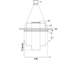
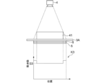
- 3 and 4 are diagrams for explaining the measurement of the scattered radiation transmittance Ts according to the body thickness of the subject H.
- a phantom 41 imitating a human body is first placed on the surface of the radiation detector 5, and then a lead plate 42 is placed on the phantom 41.
- the phantom 41 has various thicknesses such as 5 cm, 10 cm, and 20 cm, and is made of a material such as acrylic having a radiation transmittance similar to that of water, for example.
- the characteristic acquisition unit 24 acquires the radiation image K0 for measurement.
- the signal value of the radiation image K0 is larger in the region where the radiation is directly irradiated in the radiation detector 5, and the signal value is smaller in the order of the region of the phantom 41 and the region of the lead plate 42.
- the signal value should be 0 in the region of the lead plate 42 in the radiation image K0.
- the radiation scattered by the phantom 41 reaches the region corresponding to the lead plate 42 of the radiation detector 5. Therefore, the region of the lead plate 42 in the radiation image K0 has a signal value S0 corresponding to the scattered radiation component by the phantom 41.
- the phantom 41 is placed on the top plate 3A of the photographing apparatus 1, and the lead plate 42 is further placed on the phantom 41.
- the radiation source 4 is driven to irradiate the radiation detector 5 with the radiation detector 5 and the grid 6 arranged below the top plate 3A.
- the characteristic acquisition unit 24 acquires the radiation image K1 for measurement. Similar to the radiation image K0, the signal value of the radiation image K1 has a larger value in the region where the radiation is directly irradiated in the radiation detector 5, and the signal value becomes smaller in the order of the region of the phantom 41 and the region of the lead plate 42.
- the region of the lead plate 42 in the radiation image K1 has a signal value S1 corresponding to the scattered ray component by the phantom 41, the top plate 3A, and the grid 6.
- the signal value S1 includes the scattered ray component due to the top plate 3A and the grid 6, the signal value S1 is larger than the signal value S0 shown in FIG. Therefore, when the phantom 41 having a thickness of t is photographed, the scattered ray transmittance Ts of the object interposed between the subject H and the radiation detector 5, that is, the top plate 3A and the grid 6 is calculated by S1 / S0. can do.
- the characteristic acquisition unit 24 uses at least two types of phantoms having different thicknesses to calculate the scattered radiation transmittance Ts corresponding to each thickness as shown in FIGS. 3 and 4. Further, the characteristic acquisition unit 24 derives the scattered radiation transmittance Ts having a thickness not found in the phantom 41 by interpolating the scattered radiation transmittance Ts for a plurality of measured thicknesses. As a result, the characteristic acquisition unit 24 interpolates the scattered radiation transmittance for the thickness between the thicknesses, so that the body thickness distribution t of the subject H and the subject H and the radiation are as shown in FIG. A table LUT1 showing the relationship with the scattered radiation transmittance Ts of the object interposed between the detectors 5 is generated.
- FIG. 6 and 7 are diagrams for explaining the measurement of the primary line transmittance Tp according to the body thickness of the subject H.
- a phantom 41 imitating a human body is first placed on the surface of the radiation detector 5.
- the phantom 41 the same one as in the case where the scattered radiation transmittance Ts is derived is used.
- the characteristic acquisition unit 24 acquires the radiation image K2 for measurement.
- the signal value S2 in the region corresponding to the phantom 41 in the radiation image K2 includes both the primary ray component and the scattered ray component of the radiation transmitted through the phantom 41.
- the scattered radiation component of the radiation transmitted through the phantom 41 is the signal value S0 in the radiation image K0 obtained by the method shown in FIG. Therefore, the primary line component of the radiation transmitted through the phantom 41 is derived by S2-S0.
- the phantom 41 is placed on the top plate 3A of the photographing device 1, and the radiation detector 5 and the grid 6 are placed below the top plate 3A as in the case of photographing the subject H.
- the characteristic acquisition unit 24 acquires the radiation image K3 for measurement.
- the signal value S3 in the region corresponding to the phantom 41 of the radiation image K3 includes both the temporary line component and the scattered line component of the radiation transmitted through the phantom 41 and the top plate 3A and the grid 6.
- the scattered radiation component of the radiation transmitted through the phantom 41, the top plate 3A, and the grid 6 is the signal value S1 in the radiation image K1 obtained by the method shown in FIG. Therefore, the primary ray component of the radiation transmitted through the phantom 41, the top plate 3A, and the grid 6 is derived by S3-S1.
- the primary line transmittance Tp of the top plate 3A and the grid 6 interposed between the subject H and the radiation detector 5 when the phantom 41 is photographed is calculated by (S3-S1) / (S0-S2). can do.
- the characteristic acquisition unit 24 calculates the primary line transmittance Tp corresponding to each thickness as shown in FIGS. 6 and 7 by using at least two types of phantoms having different thicknesses. To do. Further, the characteristic acquisition unit 24 derives the primary line transmittance Tp having a thickness not found in the phantom 41 by interpolating the primary line transmittance Tp for the plurality of measured thicknesses. As a result, as shown in FIG. 8, the characteristic acquisition unit 24 represents the relationship between the body thickness distribution t of the subject H and the primary line transmittance Tp of the object interposed between the subject H and the radiation detector 5. Generate table LUT2.
- the tables LUT1 and LUT2 generated as described above are stored in the storage 13.
- the table is generated according to various imaging conditions (that is, radiation quality, dose and source distance), and the type of grid 6 to be used, and is stored in the storage 13.
- the characteristic acquisition unit 24 refers to the tables LUT1 and LUT2 stored in the storage 13 according to the imaging conditions acquired by the imaging condition acquisition unit 22, and refers to an object interposed between the subject H and the radiation detector 5.
- the primary ray transmittance Tp (t0) and the scattered ray transmittance Ts (t0) corresponding to the initial body thickness distribution t0 are acquired. Since the primary line transmittance Tp and the scattered line transmittance Ts also depend on the radiation quality, the primary line transmittance Tp and the scattered line transmittance Ts are Tp (kV (, mmAl), t0) and Ts (kV (kV (), respectively. , MmAl), t0).
- the line distribution derivation unit 25 uses the imaging conditions, the body thickness distribution, and the radiation characteristics of the object interposed between the subject H and the radiation detector 5, and the primary line distribution and scattering of the radiation detected by the radiation detector 5 Derivation of the line distribution.
- the primary radiation distribution Ip0 and the scattered radiation distribution Is0 after passing through the subject H are represented by the following equations (4) and (5), where t is the body thickness distribution.
- the PSF in the formula (5) is a point spread function that represents the distribution of scattered rays spreading from one pixel, and is defined according to the radiation quality and body thickness.
- * indicates a convolution operation.
- the primary line distribution Ip0 and the scattered line distribution Is0 are derived for each pixel of the radiation image G0, but (x, y) are omitted in the equations (4) and (5). Further, in the first embodiment, the body thickness distribution, the primary line distribution Ip0, and the scattered line distribution Is0 are repeatedly derived as described later, but the first primary line distribution Ip0 and the scattered line distribution Is0 In deriving, the initial body thickness distribution t0 is used as the body thickness distribution t.
- Ip0 I0 ⁇ exp ⁇ - ⁇ (t) ⁇ t ⁇ (4)
- Is0 Ip0 ⁇ STPR (kV (, mmAl), t) * PSF (kV (, mmAl), t) (5)
- the line distribution deriving unit 25 uses the primary line transmittance Tp and the scattered ray transmittance Ts of the object interposed between the subject H and the radiation detector 5 according to the following equations (6) and (7).
- the primary line distribution Ip1 and the scattered line distribution Is1 reaching the radiation detector 5 are derived.
- the sum Iw1 of the primary line distribution Ip1 and the scattered line distribution Is1 is derived by the following equation (8).
- the initial body thickness distribution t0 is used as the body thickness distribution t when the first primary line distribution Ip1 and the scattered ray distribution Is1 are derived.
- Ip1 Ip0 ⁇ Tp (kV (, mmAl), t) (6)
- Is1 Is0 ⁇ Ts (kV (, mmAl), t) (7)
- Iw1 Ip1 + Is1 (8)
- the calculation unit 26 derives an error E2 between the sum Iw1 of the primary line distribution Ip1 and the scattered line distribution Is1 and the dose at each pixel position of the radiation image G0, that is, the pixel value I1.
- the error E2 is derived by the following equation (9) or equation (9-1).
- N represents the number of pixels of the radiation image G0
- ⁇ represents the sum of all the pixels of the radiation image G0. Since the equation (9-1) calculates I1 / Iw1 in the log, the error E2 can be derived without depending on the dose applied to the subject H, that is, the reaching dose I0.
- E2 (1 / N) ⁇ ⁇ ⁇ I1-Iw1 ⁇ 2 (9)
- E2 (1 / N) ⁇ ⁇
- the calculation unit 26 updates the body thickness distribution t so that the error E2 is minimized or the error E2 is less than the predetermined threshold value Th2. Then, the calculation unit 26 repeats the acquisition of the primary line transmittance Tp and the scattered ray transmittance Ts based on the updated body thickness distribution, and the derivation of the primary line distribution Ip1 and the scattered ray distribution Is1.
- the operation performed by the calculation unit 26 is referred to as a repetitive operation. Further, in the present embodiment, the calculation unit 26 shall perform the repetitive calculation so that the error E2 is less than the predetermined threshold value Th2. Then, the calculation unit 26 outputs the processed radiation image Gm having the primary line distribution Ipm derived based on the body thickness distribution tm of the subject H whose error E2 is less than the predetermined threshold value Th2 as the pixel value. To do.
- the characteristic acquisition unit 24 and the line distribution derivation unit 25 perform the repeated acquisition of the primary line transmittance Tp and the scattered ray transmittance Ts and the derivation of the repetition of the primary line distribution Ip1 and the scattered ray distribution Is1, respectively.
- the iterative processing performed by the calculation unit 26 will be described later.
- the display control unit 27 displays the processed radiation image Gm on the display unit 8.
- FIG. 9 is a flowchart showing the processing performed in the first embodiment. It is assumed that the radiation image G0 is acquired by photographing and stored in the storage 13.
- the image acquisition unit 21 acquires the radiation image G0 from the storage 13 (step ST1).
- the shooting condition acquisition unit 22 acquires the shooting conditions when the subject H in the shooting device 1 is shot (step ST2).
- the body thickness derivation unit 23 derives the initial body thickness distribution t0 based on the radiographic image G0 and the imaging conditions (step ST3).
- the characteristic acquisition unit 24 acquires the radiation characteristics of the object interposed between the subject H and the radiation detector 5 at the time of photographing, that is, the primary ray transmittance Tp and the scattered radiation transmittance Ts (step ST4).
- the line distribution derivation unit 25 uses the imaging conditions, the body thickness distribution, and the radiation characteristics of the object interposed between the subject H and the radiation detector 5, and the primary line of radiation detected by the radiation detector 5 is used.
- the distribution Ip1 and the scattered radiation distribution Is1 are derived (step ST5). As described above, the processes of steps ST3 to ST5 are performed based on the initial body thickness distribution t0.
- FIG. 10 is a flowchart of the iterative calculation process.
- the calculation unit 26 derives an error E2 between the sum Iw1 of the primary line distribution Ip1 and the scattered line distribution Is1 and the pixel value I1 at each position of the radiation image G0 (step ST11). Then, the calculation unit 26 determines whether or not the error E2 is less than the predetermined threshold value Th2 (step ST12). When step ST12 is denied, the body thickness distribution t is updated so that the error E2 becomes small (step ST13).
- the characteristic acquisition unit 24 acquires new radiation characteristics, that is, primary ray transmittance Tp and scattered ray transmittance Ts, based on the updated body thickness distribution t (step ST14). Further, the line distribution derivation unit 25 derives a new primary line distribution Ip1 and a scattered line distribution Is1 (step ST15). Then, the calculation unit 26 returns to the process of step ST11 and repeats the processes of steps ST11 to ST15. When step ST12 is affirmed, the iterative calculation process ends.
- the calculation unit 26 pixels the primary line distribution Ipm derived based on the body thickness distribution tm of the subject H in which the error E2 is less than the predetermined threshold value Th2.
- the processed radiation image Gm to be used as a value is output (step ST7).
- the display control unit 27 displays the processed radiation image Gm on the display unit 8 (step ST8), and ends the processing.
- the body thickness distribution of the subject H is derived based on the radiation image G0 and the imaging conditions, and the radiation detection is performed using the imaging conditions, the body thickness distribution t, and the radiation characteristics of the object.
- the primary radiation distribution Ip1 and the scattered radiation distribution Is1 detected by the vessel 5 are derived.
- an error E2 between the sum Iw1 of the primary line distribution Ip1 and the scattered ray distribution Is1 and the pixel value at each position of the radiation image G0 is derived, and the error E2 is reduced to Th2 below a predetermined threshold value.
- the thickness distribution was updated, and the acquisition of radiation characteristics and the derivation of the primary line distribution and the scattered line distribution based on the updated body thickness distribution were repeated.
- the primary line distribution Ip1 and the scattered line distribution Is1 can be derived in consideration of the radiation characteristics of the object interposed between the subject H and the radiation detector 5. Since the primary line distribution Ip1 derived in this way takes into consideration the radiation characteristics of the object intervening between the subject H and the radiation detector 5, the scattered radiation component is accurately removed. There is. Therefore, according to the first embodiment, it is possible to acquire the processed radiation image Gm from which the scattered radiation component is accurately removed in consideration of the object interposed between the subject H and the radiation detector 5. ..
- the top plate 3A and the grid 6 of the photographing table 3 are used as the objects interposed between the subject H and the radiation detector 5, but as shown in FIG. 11,
- the air layer 10 may intervene between the top plate 3A and the grid 6.
- the line distribution derivation unit 25 may include the air layer 10 in the object interposed between the subject H and the radiation detector 5 to derive the primary line distribution Ip1 and the scattered line distribution Is1. preferable.
- the primary ray distribution Ip1 and the scattered ray distribution Is1 of the air layer 10 with respect to the above equations (6) and (7).
- the thickness tile of the air layer 10 is the distance between the lower surface of the top plate 3A and the surface of the grid 6 on the subject H side.
- Ip1 Ip0 ⁇ Tp (kV (, mmAl), t) * PSF air (kV (, mmAl), t air ) (6-1)
- Is1 Is0 ⁇ Ts (kV (, mmAl), t) * PSF air (kV (, mmAl), t air ) (7-1)
- FIG. 12 is a schematic block diagram showing a configuration of a radiation imaging system to which the radiation image processing apparatus according to the second embodiment of the present disclosure is applied.
- the same reference number is assigned to the same configuration as in FIG. 1, and detailed description thereof will be omitted.
- the radiographic imaging system according to the second embodiment is for capturing two radiographic images having different energy distributions and performing energy subtraction processing using the two radiographic images.
- the apparatus 1A and the console 2A including the radiographic image processing apparatus according to the second embodiment are provided.
- the imaging device 1A includes a first radiation detector 5A and a second radiation detector 5B.
- the photographing apparatus 1A in the second embodiment irradiates the first radiation detector 5A and the second radiation detector 5B with radiation emitted from the radiation source 4 and transmitted through the subject H at different energies.
- This is a photographing device for performing so-called one-shot energy subtraction.
- the first radiation detector 5A, the radiation energy conversion filter 7 made of a copper plate or the like, and the second radiation detector 5B are arranged in order from the side closest to the radiation source 4.
- the radiation source 4 is driven.
- the first and second radiation detectors 5A and 5B are in close contact with the radiation energy conversion filter 7.
- the grid 6 is arranged on the subject H side of the first radiation detector 5A as in the first embodiment.
- the first radiation detector 5A the first radiation image G1 of the subject H by low-energy radiation including so-called soft lines is acquired. Further, in the second radiation detector 5B, a second radiation image G2 of the subject H by high-energy radiation from which soft lines are removed is acquired.
- the first and second radiographic images are input to console 2A.
- FIG. 13 is a diagram showing a schematic configuration of a radiation image processing apparatus according to a second embodiment realized by installing a radiation image processing program according to the second embodiment on a computer constituting the console 2A.
- the same reference number is assigned to the same configuration as in FIG. 2, and detailed description thereof will be omitted.
- the radiographic image processing apparatus according to the second embodiment is different from the first embodiment in that it includes a subtraction unit 28.
- the subtraction unit 28 weights the first and second radiation images Gm1 and Gm2 from which the scattered ray component has been removed as described later between the corresponding pixels.
- the soft part image Gs in which the soft part is emphasized and the bone part image Gb in which the bone part is emphasized in the subject H are derived.
- ⁇ and ⁇ in the equations (10) and (11) are weighting coefficients.
- Gs ⁇ ⁇ Gm2-Gm1 (10)
- Gb ⁇ ⁇ Gm2-Gm1 (11)
- FIG. 14 is a flowchart showing the processing performed in the second embodiment. It is assumed that the first and second radiation images G1 and G2 are acquired by photographing and stored in the storage 13.
- the image acquisition unit 21 acquires the first and second radiation images G1 and G2 from the storage 13 (step ST21).
- the shooting condition acquisition unit 22 acquires the shooting conditions when the subject H in the shooting device 1 is shot (step ST22).
- the body thickness derivation unit 23 derives the initial body thickness distribution t0 based on the first or second radiographic images G1 and G2 and the imaging conditions (step ST23).
- the characteristic acquisition unit 24 acquires the radiation characteristics of the object interposed between the subject H and the radiation detector 5 at the time of photographing, that is, the primary ray transmittance Tp and the scattered radiation transmittance Ts (step ST24).
- the line distribution derivation unit 25 uses the imaging conditions, the body thickness distribution, and the radiation characteristics of the object interposed between the subject H and the radiation detector 5, and the first and second radiation detectors 5A and 5B are used.
- the primary radiation distributions Ip1-1 and Ip1-2 and the scattered radiation distributions Is1-1 and Ip1-2 detected by each of the above are derived (step ST25). As described above, the processes of steps ST23 to ST25 are performed based on the initial body thickness distribution t0.
- the calculation unit 26 repeatedly performs calculation processing (step ST26).
- the iterative calculation is the primary ray distribution Ip1-1 and the scattered ray distribution Is1-1 detected by the first radiation detector 5A, and the primary detected by the second radiation detector 5B. This is performed using each of the line distribution Ip1-2 and the scattered radiation distribution Is1-2. That is, for each of the first radiation image G1 and the second radiation image G2, the primary line distribution Ipm-1 is based on the body thickness distribution tm of the subject H in which the error E2 is less than the predetermined threshold value Th2. And the primary line distribution Ipm-2 is derived.
- the calculation unit 26 determines the primary line distribution Ipm-1 and the primary line distribution Ipm derived based on the body thickness distribution tm of the subject H in which the error E2 is less than the predetermined threshold value Th2.
- the first processed radiation image Gm1 and the second processed radiation image Gm2 having -2 as a pixel value are output (step ST27).
- the subtraction unit 28 performs the subtraction process (step ST28).
- the display control unit 27 displays the soft part image Gs and the bone part image Gb on the display unit 8 (step ST29), and ends the process.
- the subtraction processing is performed using the first and second processed radiation images Gm1 and Gm2 from which the scattered radiation component is accurately removed. Therefore, it is possible to derive high-quality soft image Gs and bone image Gb from which the scattered radiation component is removed.
- FIG. 15 is a diagram showing a schematic configuration of a radiation image processing apparatus according to a third embodiment realized by installing a radiation image processing program according to the third embodiment on a computer constituting the console 2B.
- the same reference number is assigned to the same configuration as in FIG. 13, and detailed description thereof will be omitted.
- the radiographic image processing apparatus according to the third embodiment includes a bone mineral information derivation unit 29 and a related information derivation unit 30 in addition to the subtraction unit 28 of the radiographic image processing apparatus according to the second embodiment. The provided point is different from the second embodiment.
- the bone mineral information derivation unit 29 acquires bone mineral information representing the amount of bone mineral in the bone region for each pixel of the bone region included in the first and second radiographic images G1 and G2.
- the bone mineral information deriving unit 29 derives the bone mineral information by converting the pixel value of the bone region into the pixel value of the bone image acquired under the reference imaging conditions.
- FIG. 16 is a diagram showing the relationship between the contrast between the bone portion and the soft portion with respect to the body thickness. Note that FIG. 16 shows the relationship between the contrast between the bone portion and the soft portion with respect to the body thickness at the three tube voltages of 80 kV, 90 kV and 100 kV. As shown in FIG.
- a look-up table in which the reference imaging conditions are set to, for example, a tube voltage of 90 kV is prepared.
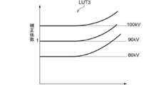
- the look-up table is for acquiring a correction coefficient for correcting a difference in contrast according to a tube voltage at the time of photographing and a decrease in contrast due to the influence of beam hardening.
- the lookup table is stored in the storage 13.
- FIG. 17 is a diagram showing a look-up table for acquiring the correction coefficient. As shown in FIG. 17, in the look-up table LUT3, the larger the tube voltage and the larger the body thickness, the larger the value of the correction coefficient.
- the correction coefficient is 1 when the tube voltage is 90 kV and the thickness is 0.
- the look-up table LUT3 is shown in two dimensions in FIG. 17, the correction coefficient differs depending on the pixel value of the bone region. Therefore, the look-up table LUT3 is actually a three-dimensional table to which an axis representing the pixel value of the bone region is added.
- the bone mineral information derivation unit 29 acquires the correction coefficient C0 for each pixel according to the body thickness distribution tm at which the imaging condition and the error E2 are less than the threshold value Th2 by referring to the look-up table LUT3.
- the correction coefficient C0 is acquired for each pixel of the bone image Gb.
- Bone mineral information B0 (x, y) is derived for each pixel of the bone region.
- the bone mineral information B0 (x, y) derived in this way is included in the radiographic image obtained by photographing the subject with a tube voltage of 90 kV, which is the reference imaging condition, and from which the influence of beam hardening is removed. It represents the pixel value of the bone portion of the bone region.
- B0 (x, y) C0 (x, y) x Gb (x, y) (12)
- the related information derivation unit 30 derives the related information related to the bone mineral information.
- the related information derivation unit 30 derives the composite image Gc in which the bone mineral information B0 is superimposed on the soft tissue image Gs generated by the subtraction unit 28 as the related information.
- the bone mineral information B0 may be superimposed on the bone image Gb to derive the composite image Gc
- the composite image Gc may be derived from either the first or second radiographic images G1 or G2.
- the composite image Gc may be derived by superimposing the bone mineral information B0.
- the display control unit 27 displays the related information on the display unit 8.
- FIG. 18 is a diagram showing related information displayed on the display unit 8. As shown in FIG. 18, the related information is the composite image Gc described above.
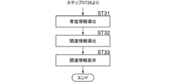
- FIG. 19 is a flowchart showing the processing performed in the third embodiment.
- the processing up to the subtraction unit 28 is the same as the processing in steps ST21 to ST28 in the second embodiment shown in FIG. 14, and therefore, in FIG. 19, FIG.
- the processing after step ST28 in the above will be described.
- the bone mineral information derivation unit 29 determines the imaging condition, the body thickness distribution, and the pixel value of the bone region in the bone image Gb. Bone mineral information representing the amount of bone mineral in the bone region is derived for each pixel of the bone region (step ST31).
- the related information derivation unit 30 derives the related information related to the bone mineral information (step ST32), the display control unit 27 displays the related information on the display unit 8 (step ST33), and the process ends.
- the bone image Gb obtained by performing subtraction processing using the first and second processed radiation images Gm1 and Gm2 from which the scattered radiation component is accurately removed. was used to derive bone mineral information and related information. Therefore, bone mineral information and related information can be accurately acquired without being affected by the scattered radiation component.
- FIG. 20 is a schematic block diagram showing a configuration of a radiation imaging system to which the radiation image processing apparatus according to the fourth embodiment of the present disclosure is applied.
- the same reference number is assigned to the same configuration as in FIG. 1, and detailed description thereof will be omitted.
- the radiographic imaging system according to the fourth embodiment includes an imaging device 1B and a console 2C including a radiographic image processing device according to the fourth embodiment.
- the photographing device 1B is a photographing device 1B capable of generating a three-dimensional image such as a cone beam CT described in Japanese Patent Application Laid-Open No. 2000-139901.
- the radiation source 4, the radiation detector 5, and the grid 6 are arranged at positions facing each other with the subject H on the top plate 3A of the photographing table 3 interposed therebetween.
- the radiation source 4, the radiation detector 5, and the grid 6 are integrally rotatable around the rotation center O1 on the top plate 3A by a driving unit (not shown).
- the acquired plurality of projected images Pk are input to the console 2C.
- FIG. 21 is a diagram showing a schematic configuration of a radiation image processing apparatus according to a fourth embodiment realized by installing a radiation image processing program according to the fourth embodiment on a computer constituting the console 2C.
- the same reference number is assigned to the same configuration as in FIG. 2, and detailed description thereof will be omitted.
- the radiation image processing apparatus according to the fourth embodiment is provided with a reconstruction unit 31 that reconstructs a plurality of projected images to generate a tomographic image of the subject H in the first embodiment. Different from.
- the reconstruction method any method such as the Feldkamp method and the Grangeat method can be used.
- the initial body thickness distribution t0 derived by the body thickness deriving unit 23 is acquired by photographing the subject H at a position where the radiation source 4 faces the subject H, that is, in the state shown in FIG. It is derived based on the projected image.
- FIG. 22 is a flowchart showing the processing performed in the fourth embodiment. It is assumed that the plurality of projected images Pk are acquired by shooting and stored in the storage 13.
- the image acquisition unit 21 acquires a plurality of projected images Pk from the storage 13 (step ST41).
- the shooting condition acquisition unit 22 acquires the shooting conditions when the subject H in the shooting device 1 is shot (step ST42).
- the body thickness derivation unit 23 derives the initial body thickness distribution t0 based on the projected image acquired at the position where the radiation source 4 faces the subject H and the imaging conditions (step ST43).
- the characteristic acquisition unit 24 acquires the radiation characteristics of the object interposed between the subject H and the radiation detector 5 at the time of photographing, that is, the primary ray transmittance Tp and the scattered radiation transmittance Ts (step ST44).
- the storage 13 stores a table showing the relationship between the body thickness t, the primary ray transmittance Tp, and the scattered ray transmittance Ts according to the thickness of the air layer in the photographing apparatus 1B.
- the characteristic acquisition unit 24 acquires the primary ray transmittance Tp and the scattered ray transmittance Ts with reference to this table.
- the line distribution derivation unit 25 uses the imaging conditions, the body thickness distribution, and the radiation characteristics of the object interposed between the subject H and the radiation detector 5, and the radiation detected by each of the plurality of projected images Pk.
- the primary line distribution Ip1-k and the scattered line distribution Is1-k are derived (step ST45). As described above, the processes of steps ST43 to ST45 are performed based on the initial body thickness distribution t0.
- the calculation unit 26 repeatedly performs calculation processing (step ST46).
- the iterative calculation is performed on the primary line distribution Ip1-k and the scattered line distribution Is1-k for each of the plurality of projected images Pk.
- the calculation unit 26 sets the primary line distribution Ipm-k derived based on the body thickness distribution tm of the subject H whose error E2 is less than the predetermined threshold value Th2 as the pixel value.
- the processed projected image Pmk is output (step ST47).
- the reconstruction unit 31 reconstructs a plurality of processed projected images Pmk (step ST48).
- tomographic images Dj for each of the plurality of tomographic planes of the subject H are derived.
- the display control unit 27 displays the tomographic image Dj on the display unit 8 (step ST49), and ends the process.
- the reconstruction process is performed using the plurality of processed projection images Pmk from which the scattered radiation component is accurately removed to generate a plurality of tomographic images Dj. Therefore, it is possible to derive a high-quality tomographic image Dj from which the scattered radiation component is removed.
- the first and second radiographic images G1 and G2 are acquired by the one-shot method, but the first and second radiographic images G1 and G2 are obtained by the so-called two-shot method in which imaging is performed twice.
- the radiographic images G1 and G2 of 2 may be acquired.
- the imaging condition acquisition unit 22 acquires both the imaging conditions when the first radiation image G1 is acquired and the imaging conditions when the second radiation image G2 is acquired.
- the first processed radiation image Gm1 is acquired based on the imaging conditions when the first radiation image G1 is acquired
- the second radiation image G2 is acquired based on the imaging conditions when the second radiation image G2 is acquired.
- the processed radiation image Gm2 of the above is acquired.
- the position of the subject H included in the first radiation image G1 and the second radiation image G2 may shift due to the body movement of the subject H. Therefore, it is preferable to perform the processing of the present embodiment after aligning the subjects in the first radiation image G1 and the second radiation image G2.
- the method described in JP-A-2011-255060 can be used.
- the method described in JP-A-2011-255060 is a plurality of first band images and a plurality of second band images representing structures having different frequency bands for each of the first and second radiographic images G1 and G2.
- the band image of the above is generated, the amount of misalignment of the positions corresponding to each other in the first band image and the second band image of the corresponding frequency band is acquired, and based on the amount of misalignment, the first radiation image G1 and The alignment with the second radiographic image G2 is performed.
- the imaging device 1B such as a cone beam CT is used to remove the scattered ray components of a plurality of projected images for generating a tomographic image, but the tomographic image is not generated.
- a radiation source is moved in parallel with a radiation detector, and a plurality of projected images are acquired by photographing a subject at a plurality of source positions, and a back projection method such as a simple back projection method or a filter back projection method is used.
- the technique of the present disclosure can be applied to the case of performing tomosynthesis imaging in which these projected images are reconstructed to generate a tomographic image by using a sequential reconstruction method or the like.
- the acquired projected image may be subjected to a process of removing the scattered radiation component in the same manner as in the fourth embodiment.
- shooting is performed using the grid 6, but the image is not limited to this.
- the technique of the present disclosure can be applied even when shooting is performed without using the grid 6.
- the object interposed between the subject H and the radiation detector 5 is the grid 6 or the grid 6 and the air layer. Therefore, a table that defines the relationship between the body thickness distribution of the subject H and the primary ray transmittance Tp and the scattered ray transmittance Ts is acquired in the same manner as in each of the above embodiments in the situation where the grid 6 is not used, and the storage 13 You can save it in.
- image processing is performed using the radiation image acquired in the system for capturing the radiation image of the subject H using the radiation detector 5 and the first and second radiation detectors 5A and 5B.
- the present disclosure can also be applied to the case of acquiring the radiographic image G0 and the first and second radiographic images G1 and G2 by using the accumulative phosphor sheet.
- two accumulating phosphor sheets are overlapped and irradiated with radiation transmitted through the subject H, and the radiation image information of the subject H is transmitted to each accumulating phosphor sheet.
- the first and second radiographic images G1 and G2 may be acquired by accumulating and recording and optically reading the radiographic image information from each accumulative phosphor sheet.
- the radiation in each of the above embodiments is not particularly limited, and in addition to X-rays, ⁇ -rays, ⁇ -rays and the like can be applied.
- the image acquisition unit 21, the imaging condition acquisition unit 22, the body thickness derivation unit 23, the characteristic acquisition unit 24, and the line distribution derivation unit of the consoles 2, 2A, 2B, and 2C which are the radiation image processing units.
- various processors processors shown below can be used.
- the various processors include CPUs, which are general-purpose processors that execute software (programs) and function as various processing units, as well as circuits after manufacturing FPGAs (Field Programmable Gate Arrays) and the like.
- Dedicated electricity which is a processor with a circuit configuration specially designed to execute specific processing such as programmable logic device (PLD), ASIC (Application Specific Integrated Circuit), which is a processor whose configuration can be changed. Circuits and the like are included.
- One processing unit may be composed of one of these various processors, or a combination of two or more processors of the same type or different types (for example, a combination of a plurality of FPGAs or a combination of a CPU and an FPGA). ) May be configured. Further, a plurality of processing units may be configured by one processor.
- one processor is configured by combining one or more CPUs and software. There is a form in which this processor functions as a plurality of processing units.
- SoC System On Chip
- the various processing units are configured by using one or more of the above-mentioned various processors as a hardware structure.
- circuitry in which circuit elements such as semiconductor elements are combined can be used.
Landscapes
- Health & Medical Sciences (AREA)
- Life Sciences & Earth Sciences (AREA)
- Engineering & Computer Science (AREA)
- Medical Informatics (AREA)
- Heart & Thoracic Surgery (AREA)
- Animal Behavior & Ethology (AREA)
- Biophysics (AREA)
- Nuclear Medicine, Radiotherapy & Molecular Imaging (AREA)
- Optics & Photonics (AREA)
- Pathology (AREA)
- Radiology & Medical Imaging (AREA)
- Biomedical Technology (AREA)
- Physics & Mathematics (AREA)
- Molecular Biology (AREA)
- Surgery (AREA)
- High Energy & Nuclear Physics (AREA)
- General Health & Medical Sciences (AREA)
- Public Health (AREA)
- Veterinary Medicine (AREA)
- Orthopedic Medicine & Surgery (AREA)
- Dentistry (AREA)
- Oral & Maxillofacial Surgery (AREA)
- Computer Vision & Pattern Recognition (AREA)
- Pulmonology (AREA)
- Theoretical Computer Science (AREA)
- Apparatus For Radiation Diagnosis (AREA)
Priority Applications (3)
| Application Number | Priority Date | Filing Date | Title |
|---|---|---|---|
| JP2021558241A JP7254963B2 (ja) | 2019-11-20 | 2020-10-26 | 放射線画像処理装置、方法およびプログラム |
| EP20891205.5A EP4062834B1 (en) | 2019-11-20 | 2020-10-26 | Radiographic image processing device, method, and program |
| US17/731,457 US11918402B2 (en) | 2019-11-20 | 2022-04-28 | Radiation image processing device, radiation image processing method, and radiation image processing program |
Applications Claiming Priority (2)
| Application Number | Priority Date | Filing Date | Title |
|---|---|---|---|
| JP2019-210027 | 2019-11-20 | ||
| JP2019210027 | 2019-11-20 |
Related Child Applications (1)
| Application Number | Title | Priority Date | Filing Date |
|---|---|---|---|
| US17/731,457 Continuation US11918402B2 (en) | 2019-11-20 | 2022-04-28 | Radiation image processing device, radiation image processing method, and radiation image processing program |
Publications (1)
| Publication Number | Publication Date |
|---|---|
| WO2021100413A1 true WO2021100413A1 (ja) | 2021-05-27 |
Family
ID=75981172
Family Applications (1)
| Application Number | Title | Priority Date | Filing Date |
|---|---|---|---|
| PCT/JP2020/040149 Ceased WO2021100413A1 (ja) | 2019-11-20 | 2020-10-26 | 放射線画像処理装置、方法およびプログラム |
Country Status (4)
| Country | Link |
|---|---|
| US (1) | US11918402B2 (https=) |
| EP (1) | EP4062834B1 (https=) |
| JP (1) | JP7254963B2 (https=) |
| WO (1) | WO2021100413A1 (https=) |
Families Citing this family (2)
| Publication number | Priority date | Publication date | Assignee | Title |
|---|---|---|---|---|
| JP2024048121A (ja) * | 2022-09-27 | 2024-04-08 | キヤノン株式会社 | 情報処理装置、放射線撮影システム、情報処理方法及びプログラム |
| JP2025006434A (ja) * | 2023-06-29 | 2025-01-17 | キヤノン株式会社 | 画像処理装置、放射線撮像システム、画像処理方法及びプログラム |
Citations (5)
| Publication number | Priority date | Publication date | Assignee | Title |
|---|---|---|---|---|
| JP2000139901A (ja) | 1998-11-13 | 2000-05-23 | Fuji Photo Film Co Ltd | 放射線画像形成装置 |
| JP2011255060A (ja) | 2010-06-11 | 2011-12-22 | Fujifilm Corp | 画像位置合わせ装置および方法並びにプログラム |
| JP2015043959A (ja) | 2013-07-31 | 2015-03-12 | 富士フイルム株式会社 | 放射線画像解析装置および方法並びにプログラム |
| JP2016067587A (ja) * | 2014-09-30 | 2016-05-09 | 富士フイルム株式会社 | 放射線画像処理装置および方法並びにプログラム |
| JP2017225525A (ja) | 2016-06-21 | 2017-12-28 | 富士フイルム株式会社 | 放射線画像処理装置、方法およびプログラム |
Family Cites Families (6)
| Publication number | Priority date | Publication date | Assignee | Title |
|---|---|---|---|---|
| JP6042855B2 (ja) * | 2014-03-28 | 2016-12-14 | 富士フイルム株式会社 | 放射線画像撮影装置、放射線画像撮影方法、及び放射線画像撮影プログラム |
| JP6400947B2 (ja) | 2014-05-27 | 2018-10-03 | コーニンクレッカ フィリップス エヌ ヴェKoninklijke Philips N.V. | グリッド同様のコントラスト強調のためのx線撮像システム及び方法 |
| US9615808B2 (en) | 2014-05-27 | 2017-04-11 | Koninklijke Philips N.V. | Method and radiography system for grid-like contrast enhancement |
| JP6296553B2 (ja) | 2014-09-30 | 2018-03-20 | 富士フイルム株式会社 | 放射線画像撮影装置および放射線画像撮影装置の作動方法 |
| JP6695232B2 (ja) * | 2016-07-29 | 2020-05-20 | 富士フイルム株式会社 | 放射線画像撮影システム |
| WO2020241664A1 (ja) * | 2019-05-27 | 2020-12-03 | 富士フイルム株式会社 | 放射線画像処理装置及び放射線画像処理方法 |
-
2020
- 2020-10-26 WO PCT/JP2020/040149 patent/WO2021100413A1/ja not_active Ceased
- 2020-10-26 JP JP2021558241A patent/JP7254963B2/ja active Active
- 2020-10-26 EP EP20891205.5A patent/EP4062834B1/en active Active
-
2022
- 2022-04-28 US US17/731,457 patent/US11918402B2/en active Active
Patent Citations (5)
| Publication number | Priority date | Publication date | Assignee | Title |
|---|---|---|---|---|
| JP2000139901A (ja) | 1998-11-13 | 2000-05-23 | Fuji Photo Film Co Ltd | 放射線画像形成装置 |
| JP2011255060A (ja) | 2010-06-11 | 2011-12-22 | Fujifilm Corp | 画像位置合わせ装置および方法並びにプログラム |
| JP2015043959A (ja) | 2013-07-31 | 2015-03-12 | 富士フイルム株式会社 | 放射線画像解析装置および方法並びにプログラム |
| JP2016067587A (ja) * | 2014-09-30 | 2016-05-09 | 富士フイルム株式会社 | 放射線画像処理装置および方法並びにプログラム |
| JP2017225525A (ja) | 2016-06-21 | 2017-12-28 | 富士フイルム株式会社 | 放射線画像処理装置、方法およびプログラム |
Non-Patent Citations (1)
| Title |
|---|
| See also references of EP4062834A4 |
Also Published As
| Publication number | Publication date |
|---|---|
| EP4062834B1 (en) | 2024-04-17 |
| EP4062834A1 (en) | 2022-09-28 |
| JP7254963B2 (ja) | 2023-04-10 |
| JPWO2021100413A1 (https=) | 2021-05-27 |
| US11918402B2 (en) | 2024-03-05 |
| US20220249049A1 (en) | 2022-08-11 |
| EP4062834A4 (en) | 2022-12-21 |
Similar Documents
| Publication | Publication Date | Title |
|---|---|---|
| US10235766B2 (en) | Radiographic image analysis device and method, and storage medium having stored therein program | |
| JP2017143943A (ja) | 放射線画像処理装置、方法およびプログラム | |
| JP6556005B2 (ja) | 断層画像生成装置、方法およびプログラム | |
| JP7662442B2 (ja) | 推定装置、方法およびプログラム | |
| WO2013128891A1 (ja) | 画像処理装置および方法 | |
| JP6301439B2 (ja) | 放射線画像解析装置および方法並びにプログラム | |
| US11918402B2 (en) | Radiation image processing device, radiation image processing method, and radiation image processing program | |
| JP2022013679A (ja) | 医用画像処理方法、医用画像処理装置及びx線ct装置 | |
| US12611157B2 (en) | Radiation image processing device, radiation image processing method, and radiation image processing program | |
| WO2011058612A1 (ja) | 放射線撮影装置 | |
| JP2015019863A (ja) | 放射線断層撮影装置及びプログラム | |
| JP2021058363A (ja) | 画像処理装置、方法およびプログラム | |
| JP2018038638A (ja) | 画像処理装置、方法およびプログラム | |
| US20080075379A1 (en) | Image processing device and image processing method | |
| JP2022026205A (ja) | 放射線画像処理装置、方法およびプログラム | |
| JP7284816B2 (ja) | 放射線画像処理装置及び放射線画像処理方法 | |
| JP7690362B2 (ja) | 脂肪量導出装置、方法およびプログラム | |
| JP2008125691A (ja) | 放射線画像演算方法および装置並びにプログラム | |
| JP7376448B2 (ja) | 制御装置、制御方法、及び制御プログラム | |
| US12533098B2 (en) | Radiation image processing device, radiation image processing method, and radiation image processing program | |
| JP7531337B2 (ja) | 放射線撮影システム、制御装置、制御方法、及びプログラム | |
| WO2021095447A1 (ja) | 画像処理装置、放射線撮影装置、画像処理方法及びプログラム | |
| JP2022055224A (ja) | 制御装置、制御方法、及び制御プログラム | |
| JP2024042609A (ja) | 放射線画像処理装置、その作動方法、及び放射線画像処理プログラム | |
| JP2023177980A (ja) | 放射線画像処理装置、方法およびプログラム |
Legal Events
| Date | Code | Title | Description |
|---|---|---|---|
| 121 | Ep: the epo has been informed by wipo that ep was designated in this application |
Ref document number: 20891205 Country of ref document: EP Kind code of ref document: A1 |
|
| ENP | Entry into the national phase |
Ref document number: 2021558241 Country of ref document: JP Kind code of ref document: A |
|
| NENP | Non-entry into the national phase |
Ref country code: DE |
|
| ENP | Entry into the national phase |
Ref document number: 2020891205 Country of ref document: EP Effective date: 20220620 |