WO2021095549A1 - 超音波モータ - Google Patents
超音波モータ Download PDFInfo
- Publication number
- WO2021095549A1 WO2021095549A1 PCT/JP2020/040663 JP2020040663W WO2021095549A1 WO 2021095549 A1 WO2021095549 A1 WO 2021095549A1 JP 2020040663 W JP2020040663 W JP 2020040663W WO 2021095549 A1 WO2021095549 A1 WO 2021095549A1
- Authority
- WO
- WIPO (PCT)
- Prior art keywords
- vibrating body
- main surface
- ultrasonic motor
- wiring portion
- piezoelectric element
- Prior art date
- Legal status (The legal status is an assumption and is not a legal conclusion. Google has not performed a legal analysis and makes no representation as to the accuracy of the status listed.)
- Ceased
Links
Images









Classifications
-
- H—ELECTRICITY
- H02—GENERATION; CONVERSION OR DISTRIBUTION OF ELECTRIC POWER
- H02N—ELECTRIC MACHINES NOT OTHERWISE PROVIDED FOR
- H02N2/00—Electric machines in general using piezoelectric effect, electrostriction or magnetostriction
- H02N2/10—Electric machines in general using piezoelectric effect, electrostriction or magnetostriction producing rotary motion, e.g. rotary motors
- H02N2/16—Electric machines in general using piezoelectric effect, electrostriction or magnetostriction producing rotary motion, e.g. rotary motors using travelling waves, i.e. Rayleigh surface waves
- H02N2/163—Motors with ring stator
-
- H—ELECTRICITY
- H02—GENERATION; CONVERSION OR DISTRIBUTION OF ELECTRIC POWER
- H02N—ELECTRIC MACHINES NOT OTHERWISE PROVIDED FOR
- H02N2/00—Electric machines in general using piezoelectric effect, electrostriction or magnetostriction
- H02N2/10—Electric machines in general using piezoelectric effect, electrostriction or magnetostriction producing rotary motion, e.g. rotary motors
- H02N2/16—Electric machines in general using piezoelectric effect, electrostriction or magnetostriction producing rotary motion, e.g. rotary motors using travelling waves, i.e. Rayleigh surface waves
- H02N2/166—Motors with disc stator
-
- H—ELECTRICITY
- H02—GENERATION; CONVERSION OR DISTRIBUTION OF ELECTRIC POWER
- H02N—ELECTRIC MACHINES NOT OTHERWISE PROVIDED FOR
- H02N2/00—Electric machines in general using piezoelectric effect, electrostriction or magnetostriction
- H02N2/0005—Electric machines in general using piezoelectric effect, electrostriction or magnetostriction producing non-specific motion; Details common to machines covered by H02N2/02 - H02N2/16
- H02N2/0075—Electrical details, e.g. drive or control circuits or methods
- H02N2/0085—Leads; Wiring arrangements
Definitions
- the present invention relates to an ultrasonic motor having a plurality of piezoelectric elements.
- Patent Document 1 a piezoelectric element is attached to one surface of a stator.
- a flexible wiring member is joined to the piezoelectric element in order to send an electric signal to the piezoelectric element. Physically, this wiring member is fixed to the stator at the end of the stator and is pulled out of the stator.
- the stator vibrates repeatedly by exciting the piezoelectric element.
- this wiring member is fixed to the end portion of the stator. Therefore, in the portion where the wiring member is fixed, disconnection or noise may occur due to repeated vibration. In addition, vibration may leak and the characteristics of the motor may deteriorate.
- An object of the present invention is to provide an ultrasonic motor capable of stabilizing the vibration of a stator, which is less likely to cause disconnection or noise of wiring.
- the ultrasonic motor of the present invention has a plate-shaped vibrating body including a first main surface and a second main surface facing each other, and a first main surface provided on the first main surface of the vibrating body.
- a stator having a piezoelectric element and a second piezoelectric element, a rotor in direct or indirect contact with the second main surface of the vibrating body, and the first piezoelectric element and the second piezoelectric element.
- the first piezoelectric element and the second piezoelectric element are arranged along the circumferential direction of the traveling wave so as to generate a traveling wave that orbits around the axial direction by vibrating the vibrating body.
- the wiring member includes a first connecting member and a second connecting member connected to the first piezoelectric element and the second piezoelectric element, respectively, and the first connecting member and the second connecting member.
- It has a central wiring portion connected to a member and provided in a region including an axial center, and a lead-out wiring portion connected to the central wiring portion, and the central wiring portion is of the vibrating body. It is fixed to the first main surface, and the lead-out wiring portion is floated from the first main surface of the vibrating body.
- FIG. 1 is a perspective view of an ultrasonic motor according to a first embodiment of the present invention.
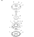
- FIG. 2 is an exploded perspective view of the ultrasonic motor according to the first embodiment of the present invention.
- FIG. 3 is an exploded perspective view for explaining the relationship between the vibrating body, the piezoelectric element, and the wiring member in the ultrasonic motor according to the first embodiment of the present invention.
- FIG. 4A is a front view for explaining a portion where the stator and rotor of the ultrasonic motor of the first embodiment are laminated, and
- FIG. 4B shows details of the piezoelectric element. It is a front sectional view.
- FIG. 1 is a perspective view of an ultrasonic motor according to a first embodiment of the present invention.
- FIG. 2 is an exploded perspective view of the ultrasonic motor according to the first embodiment of the present invention.
- FIG. 3 is an exploded perspective view for explaining the relationship between the vibrating body, the piezoelectric element, and the wiring member in the ultras
- FIG. 5A is a plan view for explaining the structure of the vibrating body on the first main surface side and the wiring member in the ultrasonic motor according to the first embodiment of the present invention.
- b) is a cross-sectional view taken along the line ZZ in FIG. 5 (a), and is a partially cutaway front cross-sectional view for explaining the relationship between the central wiring portion and the lead wiring portion and the vibrating body.
- FIG. 6 is a plan view for explaining the first and second signal wirings provided on the wiring member.
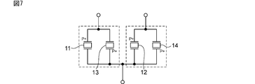
- FIG. 7 is a circuit diagram for explaining a circuit for applying a drive signal to the piezoelectric element in the first embodiment of the present invention.
- FIG. 8 is a bottom view of a stator for explaining an excited traveling wave in the first embodiment of the present invention.
- FIG. 9 is a schematic front view of a stator for explaining an excited traveling wave in the first embodiment of the present invention.
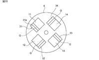
- FIG. 10 is a bottom view for explaining a stator in an ultrasonic motor according to a second embodiment of the present invention.
- FIG. 11 is a bottom view for explaining a stator and a wiring member in the ultrasonic motor according to the second embodiment of the present invention.
- FIG. 12 is a circuit diagram for explaining a drive circuit of an ultrasonic motor according to a second embodiment of the present invention.
- FIG. 13 is a bottom view for explaining the stator of the ultrasonic motor according to the third embodiment of the present invention.
- FIG. 14 is a bottom view for explaining the stator of the ultrasonic motor according to the fourth embodiment of the present invention.
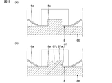
- FIG. 15 (a) to 15 (c) are schematic front views for explaining the effect of the pressurizing spring.
- FIG. 16 is a bottom view showing the configuration of the pressurizing spring of the fifth embodiment and the vibrating body in the stator.
- FIG. 17 is a cross-sectional view taken along the line II in FIG. 18 (a) and 18 (b) are schematic cross-sectional views for explaining an example of a method of forming a fixed portion.
- FIG. 19 is a front sectional view of the vibration device according to the sixth embodiment.
- FIG. 20 is a plan view of the pressurization spring according to the sixth embodiment.
- FIG. 21 is a plan view showing the configuration of the pressurizing spring and the vibrating body in the sixth embodiment.
- FIG. 22 is a perspective view showing an example of a mode in which the claw portion of the pressurizing spring according to the sixth embodiment is fixed to the vibrating body.
- FIG. 23 is a front sectional view showing the configuration of the pressurizing spring and the vibrating body in the seventh embodiment.
- FIG. 24 is a perspective view showing the configuration of the pressurization spring according to the seventh embodiment.
- FIG. 25 is a front sectional view showing an example of a method of fitting the pressurizing spring and the vibrating body in the seventh embodiment.
- FIG. 1 is a perspective view of an ultrasonic motor according to a first embodiment of the present invention
- FIG. 2 is an exploded perspective view thereof
- FIG. 3 is an exploded perspective view showing a stator and a wiring member.
- the ultrasonic motor 1 has a first case member 2 and a second case member 3.
- the second case member 3 is fixed to the first case member 2, and the case of the ultrasonic motor 1 is configured.
- the stator 4 and the rotor 5 are housed in the storage space of this case.
- the stator 4 has a vibrating body 6 made of a metal plate.
- the vibrating body 6 is not particularly limited, but has a disk-shaped shape.
- the vibrating body 6 may be made of a material other than metal.
- the vibrating body 6 has a first main surface 6a and a second main surface 6b.
- the first main surface 6a and the second main surface 6b face each other.
- the first to fourth piezoelectric elements 11 to 14 shown in FIG. 3 are fixed to the first main surface 6a of the vibrating body 6.
- the planar shape of the first to fourth piezoelectric elements 11 to 14 may be elliptical, and the planar shape is not particularly limited.
- the first to fourth piezoelectric elements 11 to 14 are connected to the connector 9 via the wiring member 15.
- the first to fourth piezoelectric elements 11 to 14 are provided, but in the ultrasonic motor of the present invention, the stator is at least the first piezoelectric element 11 and the second piezoelectric element 12. It suffices to have. Two or more arbitrary numbers of piezoelectric elements can be used to generate the traveling wave described later. Therefore, in addition to the first and second piezoelectric elements 11 and 12, the third and fourth piezoelectric elements 13 and 14 can be used as at least one other piezoelectric element.
- a plurality of protrusions 6c are provided on the second main surface 6b of the vibrating body 6.
- the plurality of protrusions 6c are provided so as to form an annular shape.
- the plurality of protrusions 6c are pressed against the friction material 5c attached to the surface of the rotor 5.
- the first to fourth piezoelectric elements 11 to 14 are excited to generate a traveling wave traveling in the circumferential direction in the vibrating body 6.
- the rotor 5 is rotated by this traveling wave.
- pressure welding means applying pressure to bring them into contact with each other, that is, pressing them.
- the rotor 5 is indirectly in contact with the second main surface 6b of the vibrating body 6 via the friction material 5c.
- the friction material 5c may not be used. That is, the rotor 5 may be in direct contact with the second main surface 6b of the vibrating body 6.
- the first piezoelectric element 11 has a structure in which electrodes 17 and 18 are provided on both main surfaces of the piezoelectric ceramic layer 16.
- the electrode 17 is attached to the first main surface 6a of the vibrating body 6 with an adhesive.
- the thickness of this adhesive is very thin. Therefore, the electrode 17 is electrically connected to the vibrating body 6.
- the second to fourth piezoelectric elements 12 to 14 also have a similar structure.
- the feature of this embodiment is the lead-out portion from the vibrating body 6 to the connector 9 in the wiring member 15. This will be described with reference to FIGS. 5 (a) and 5 (b) and FIG.
- the wiring member 15 includes first to fourth connecting members 21a to 21d connected to the first to fourth piezoelectric elements 11 to 14, a central wiring portion 23, and a lead-out wiring portion 24.
- the central wiring portion 23 is provided in a region including the axial center which is the above-mentioned rotation center of the first main surface 6a of the vibrating body 6.
- the central wiring portion 23 is arranged in the region including the center of the first main surface 6a of the disk-shaped vibrating body 6, but is deviated from the center of the vibrating body depending on the planar shape of the vibrating body.
- a central wiring portion may be provided at a vertical position. That is, as long as the central wiring portion includes the axial center which is the center of rotation, it may be provided in the region which does not include the center of the first main surface of the vibrating body.
- two or more piezoelectric elements can be used. Therefore, in addition to the first and second connecting members 21a and 21b, at least one other connecting member, for example, the third and fourth connecting members 21c and 21d can be provided.
- a first signal is given to the first and third piezoelectric elements 11 and 13 facing each other.
- a second signal whose phase is inverted with respect to the first signal is added to the second and fourth piezoelectric elements 12 and 14.
- the wiring member 15 has a base material made of a flexible resin such as polyimide, and signal wiring laminated or embedded in the base material. This signal wiring is made of a metal leaf such as Cu foil or other conductive material.
- FIG. 6 shows the first and second signal wirings D and E with broken lines.
- the first signal wiring D passes through the first and third connecting members 21a and 21c, the central wiring portion 23, and the lead wiring portion 24.
- the second signal wiring E passes through the second and fourth connecting members 21b and 21d, the central wiring portion 23, and the lead wiring portion 24.
- the first to fourth connecting members 21a to 21d of the wiring member 15 are joined to the outer electrodes of the first and third piezoelectric elements 11 and 13 or the second and fourth piezoelectric elements 12 and 14.
- the other end is connected to the central wiring portion 23.
- the central wiring portion 23 is fixed on the first main surface 6a of the vibrating body 6 with an adhesive.
- a plurality of first to fourth connecting members 21a to 21d are radially extended from the central wiring portion 23 toward the outer peripheral edge side of the vibrating body 6.
- the number of piezoelectric elements is not limited to four, and may be two or any number of three or more.
- the first and second connecting members are extended from the central wiring portion toward the outer peripheral edge of the vibrating body, and the first connecting member and the second connecting member The angle formed by is 180 °. Further, when functioning as a traveling wave ring motor, 4n piezoelectric elements are required.
- the lead-out wiring portion 24 of the wiring member 15 is a portion outside the broken line F in FIGS. 5A and 6. As shown in FIG. 5B, the lead-out wiring portion 24 is floated from the first main surface 6a of the vibrating body 6.
- a stress absorbing portion 25 is provided in the middle of the lead-out wiring portion 24.
- the stress absorbing portion 25 is formed so that a part of the lead-out wiring portion 24 is branched and merges on the outside of the through hole 25a.
- the stress absorbing portion 25 can relieve the tensile stress applied to the lead-out wiring portion 24. Thereby, the leakage of vibration can be suppressed more effectively.
- the shape of the stress absorbing portion 25 is not limited to the one shown in the drawing, and an appropriate structure for relaxing the tensile stress can be adopted.
- the central wiring portion 23 has an opening 23a, although it is not essential.
- the opening 23a is a region including an axial center which is a rotation center of the rotor 5 in the ultrasonic motor 1.
- the vibrating body 6 In order to rotate the rotor 5, the vibrating body 6 generates a traveling wave traveling in the circumferential direction. In this case, the axial center of the vibrating body 6 is a portion that is hardly displaced. On the other hand, on the first main surface 6a of the vibrating body 6, the vicinity of the outer peripheral edge and the regions where the first to fourth piezoelectric elements 11 to 14 are provided are largely displaced.
- the wiring member 15 is fixed to the first main surface 6a in the central wiring portion 23 that hardly displaces in the state where the traveling wave is generated.
- the lead-out wiring portion 24 is floated from the first main surface 6a. Therefore, even if the vibrating body 6 repeatedly vibrates in order to generate a traveling wave during driving, it is unlikely that the wiring member 15 will be disconnected or make noise.
- the central wiring portion 23 is fixed to the part where vibration hardly occurs, vibration is unlikely to leak. Therefore, the vibration of the stator 4 can be stabilized, and the deterioration of the motor characteristics is unlikely to occur.
- the first and second signals are given to the piezoelectric elements of the first and third piezoelectric elements 11 and 13 and the second and fourth piezoelectric elements 12 and 14, respectively.
- WO2010 / 061508A1 discloses a structure in which a plurality of piezoelectric elements are dispersedly arranged in the circumferential direction and driven to generate a traveling wave in the stator.
- the structure for generating this traveling wave not only the following description but also the detailed description will be omitted by referring to the configuration described in WO2010 / 061508A1 in the present specification.
- FIG. 8 is a bottom view for explaining the traveling wave in an easy-to-understand manner
- FIG. 9 is a schematic front view of the stator.
- three standing waves X and Y are shown.
- the first to fourth piezoelectric elements 11 to 14 are arranged at a central angle of 30 °.
- each of the first to fourth piezoelectric elements 11 to 14 has a circumferential dimension occupying a central angle of 60 °.
- three standing waves X and Y having a phase difference of 90 ° are excited, and both are combined to generate a traveling wave.
- a +, A ⁇ , B +, and B ⁇ in FIG. 8 indicate the polarization directions of the piezoelectric ceramic layer 16.
- + Means that the polarization direction is directed from the first main surface to the second main surface in the thickness direction.
- A indicates that it is the first piezoelectric element 11 and the third piezoelectric element 13
- B indicates that it is the second piezoelectric element 12 and the fourth piezoelectric element 14.
- the rotor 5 pressed against the second main surface 6b of the vibrating body 6 rotates around the center in the axial direction.
- the configuration for generating a traveling wave is not limited to the configuration shown in FIG. 8, and various conventionally known configurations for generating a traveling wave can be used.
- the rotor 5 has a disk-shaped rotor body 5a and a rotating shaft 5b having one end connected to the rotor body 5a.
- the rotating shaft 5b extends toward the side opposite to the stator 4 and passes through the axial center.
- the rotor body 5a rotates, and the rotating shaft 5b rotates accordingly.
- the friction material 5c is fixed to the lower surface of the rotor body 5a of the rotor 5 and is provided to increase the frictional force between the rotor 5 and the vibrating body 6.
- a PTFE-based liner material or the like can be used for the friction material 5c.
- the first case member 2 is provided with a cross-shaped recess 2a on the upper surface.
- a pressurizing spring 8 as a pressurizing member is arranged between the first main surface 6a of the vibrating body 6 and the first case member 2.
- the pressurizing spring 8 has a cross-shaped shape in a plan view, and the tip of the cross-shaped portion is fitted with the cross-shaped portion of the recess 2a.
- the pressurization spring 8 does not rotate with respect to the axial center, and the center of the shaft and the center of the pressurization spring 8 are aligned with each other.
- a long hole is formed in the upper part of the pressurization spring 8, and the protrusion on the back surface of the stator 4 is formed so as to enter the long hole. ..
- the pressurization spring 8 applies pressurization to pressurize the vibrating body 6 to the rotor 5 side.
- the first case member 2 and the second case member 3 are fixed, and the pressurization is applied by the elastic force of the pressurization spring 8.
- an appropriate fixing structure such as a method using a bolt and a nut for inserting the through hole 2b and the through hole 3c can be used.
- a metal such as aluminum or stainless steel, or a resin such as PBT (polybutylene terephthalate) or PPS (polyphenylene sulfide) can be used. ..
- the second case member 3 is provided with a cylindrical protrusion 3a having a through hole 3b in the center.
- the bearing 7 is housed in the through hole 3b, and the rotating shaft 5b is inserted into the through hole of the bearing 7.
- the bearing 7 is used in this embodiment, other bearings such as a sliding bearing may be used.
- FIG. 10 is a bottom view for explaining a structure in which the vibrating body 6 and the first to fourth piezoelectric elements 11 to 14 are attached to the ultrasonic motor according to the second embodiment of the present invention.
- FIG. 11 is a bottom view showing a structure in which the wiring member 15 is further attached to the first to fourth piezoelectric elements 11 to 14.
- the first to fourth detection elements 31 to 34 are provided integrally with the first to fourth piezoelectric elements 11 to 14. That is, on the outer surface of the piezoelectric ceramic layer 16, the first to fourth detection elements 31 to 34 are formed by separating the gap G from one electrode of the first to fourth piezoelectric elements 11 to 14. Electrodes are provided. Taking the first detection element 31 as an example, the detection electrode is an electrode 31a located outside the piezoelectric ceramic layer 16. The ground potential is on the first main surface 6a side of the vibrating body 6. A detection unit for detecting the vibration of the piezoelectric ceramic layer 16 between the electrode on the ground potential side and the electrode 31a is configured. The second to fourth detection elements 32 to 34 are similarly configured.
- the wiring member 15 is also provided with a signal wiring through which an electric signal detected from the first to fourth detection elements 31 to 34 flows.
- FIG. 12 is a circuit diagram for explaining a drive circuit of an ultrasonic motor having such first to fourth detection elements 31 to 34.
- the drive signal is output from the control device 41 via the amplifier 42.
- the phase-adjusted signals are given to the first and third piezoelectric elements 11 and 13 and the second and fourth piezoelectric elements 12 and 14 by the first phase circuit 43 and the second phase circuit 44. Be done. Thereby, the vibrating body 6 is driven.
- the amplifier 45 is connected between the first phase circuit 43 and the first and third piezoelectric elements 11 and 13. Similarly, an amplifier 46 is provided between the second phase circuit 44 and the second and fourth piezoelectric elements 12 and 14.
- the signals extracted by the first to fourth detection elements 31 to 34 are amplified by the amplifiers 47 to 50 and given to the control device 41.
- the control device 41 adjusts the voltage of the drive signal for driving the first to fourth piezoelectric elements 11 to 14 based on the signal corresponding to the detected actual excitation state. In this way, the drive of the ultrasonic motor can be stabilized.
- FIG. 13 describes the structures of the first to fourth piezoelectric elements 11 to 14, the first to fourth detection elements 31 to 34, and the vibrating body 6 of the ultrasonic motor according to the third embodiment of the present invention. It is a bottom view for this.
- the first to fourth detection elements 31 to 34 may be provided so that the first to fourth detection elements 31 to 34 are located on the rotation center side.
- FIG. 14 describes the structures of the first to fourth piezoelectric elements 11 to 14, the first to fourth detection elements 31 to 34, and the vibrating body 6 of the ultrasonic motor according to the fourth embodiment of the present invention. It is a bottom view for this.
- the first to fourth detection elements 31 to 34 may be separated from the first to fourth piezoelectric elements 11 to 14 by an L-shaped gap G.
- the elongated hole of the pressurization spring 8 and the protrusion on the back surface of the stator 4 are fitted.
- the protrusion is provided on the first main surface 6a of the vibrating body 6 of the stator 4.
- the protrusions are substantially elliptical columnar.
- 15 (a) to 15 (c) are schematic front views for explaining the effect of the pressurizing spring.
- the positional relationship between the rotor body 5a of the rotor 5 and the rotating shaft 5b shown in FIG. 15A may vary during manufacturing.
- the rotor body 5a and the rotating shaft 5b are not integrated and the rotating shaft 5b is inserted through the rotor body 5a, the positional relationship between the rotor body 5a and the rotating shaft 5b may be displaced.
- the rotation of the rotor 5 tends to fluctuate. Even if the rotation shake is within an acceptable range, the rotation speed may become unstable due to the rotation shake.
- the position shift due to the rotation of the pressurizing spring 8 and the vibrating body 6 can be effectively suppressed.
- the pressurization of the pressurization spring 8 on the stator 4 and the rotor 5 can be stabilized even if the rotation is shaken. Therefore, the rotation speed of the ultrasonic motor 1 can be stabilized more reliably.
- FIG. 16 is a bottom view showing the configuration of the pressurizing spring of the fifth embodiment and the vibrating body in the stator.
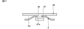
- FIG. 17 is a cross-sectional view taken along the line II in FIG.
- the present embodiment is different from the first embodiment in that the protruding portion 67 of the vibrating body 66 includes the fixed portion 67a. Except for the above points, the ultrasonic motor of the present embodiment has the same configuration as the ultrasonic motor 1 of the first embodiment.
- the protrusion 67 is provided on the first main surface 6a of the vibrating body 66.
- a fixing portion 67a is provided at the tip of the protrusion 67.
- the cross-sectional area of the fixed portion 67a in the protruding portion 67 is wider than the cross-sectional area of the other portion.
- the cross-sectional area of the protrusion 67 is the area of the cross section parallel to the first main surface 6a of the vibrating body 66.
- the pressurization spring 8 As shown in FIG. 17, the protrusion 67 and the elongated hole 8a of the pressurization spring 8 are fitted. In addition to this, the pressurization spring 8 is sandwiched between the first main surface 6a of the vibrating body 66 and the fixing portion 67a. As a result, the pressurization spring 8 can be fixed more reliably, and the positional deviation due to the rotation of the vibrating body 66 and the pressurization spring 8 can be suppressed even more reliably.
- 18 (a) and 18 (b) are schematic cross-sectional views for explaining an example of a method of forming a fixed portion.
- the protrusion and the elongated hole 8a similar to those in the first embodiment are fitted.
- a punch is struck at the tip of the protrusion 67.
- the protrusion 67 is deformed, the width of the protrusion 67 is widened, and the fixing portion 67a is formed.
- a recess 67c is formed in the fixing portion 67a.
- the protrusion may be deformed by a method other than the above to form the fixing portion 67a.
- the fixing portion 67a may be provided without forming the recess 67c by applying pressure with a jig other than the punch.
- FIG. 19 is a front sectional view of the vibration device according to the sixth embodiment.
- the configurations of the first case member 72, the rotor 75, the vibrating body 76, and the pressurization spring 78 are different from those in the first embodiment. Except for the above points, the ultrasonic motor of the present embodiment has the same configuration as the ultrasonic motor 1 of the first embodiment.
- the outer shape of the rotor body 75a of the rotor 75 is a disk shape as in the first embodiment.
- the rotor body 75a has a through hole 75c.
- the through hole 75c is located in the center of the rotor body 75a.
- the rotating shaft 75b is inserted through the through hole 75c.
- the position of the through hole 75c is not limited to the above.
- the through hole 75c may be located in a region including the axial center.
- a through hole 76c is provided in the center of the vibrating body 76.
- the position of the through hole 76c is not limited to the above.
- the through hole 76c may be located in a region including the axial center.
- FIG. 20 is a plan view of the pressurization spring according to the sixth embodiment.
- FIG. 21 is a plan view showing the configuration of the pressurizing spring and the vibrating body in the sixth embodiment.
- the pressurization spring 78 of the present embodiment is different from the first embodiment in that it has the shape of the hole 78a and the claw portion 78b.
- the pressurization spring 78 configuration other than the above points is the same as that of the pressurization spring 8 of the first embodiment.
- a pair of claw portions 78b is provided in a part of the portion of the pressurization spring 78 in contact with the hole 78a.
- a pair of claws 78b extend toward the stator.
- a pair of claw portions 78b face each other with a hole 78a in between.
- the claw portions 78b are not limited to one pair.
- the claw portion 78b and the through hole 76c of the vibrating body 76 are fitted.
- the tip of the claw portion 78b is welded to the vibrating body 76.
- the claw portion 78b may be fixed to the vibrating body 76 by a method other than welding.
- the claw portion 78b may be fixed to the vibrating body 76 by caulking.
- a flat punch or the like may be struck at the tip of the claw portion 78b.
- a groove 78c is formed at the tip of the claw portion 78b.
- the claw portion 78b may be deformed by a method other than the above.
- the pressurization spring 78 can be stably fixed to the vibrating body 76.
- the claw portions 78b may be provided at odd-numbered locations such as 0.5 pair and 2.5 pairs.
- the rotating shaft 75b is inserted through the through hole 76c of the vibrating body 76 and the hole 78a of the pressurizing spring 78. More specifically, in a state where the claw portion 78b and the through hole 76c are fitted, the pair of claw portions 78b face each other with a substantially cylindrical portion of the through hole 76c. A rotating shaft 75b passes between a pair of claw portions 78b.
- a cylindrical protrusion 72d having a through hole 72c is provided in the center of the first case member 72.
- the bearing 77 is housed in the through hole 72c.
- the vicinity of the end of the rotating shaft 75b is in contact with the bearing 77.
- the bearing 77 is a sliding bearing.
- the bearing 77 may be another bearing such as a bearing.
- the rotating shaft 75b is configured as a double-sided bearing on both the first case member 72 side and the second case member 3 side. This makes it possible to support various motor structures.
- the inner wall of the portion of the first case member 72 in the case is provided with the same recess 2a as in the first embodiment.
- the pressurization spring 78 is located between the inner wall and the stator.
- the pressurization spring 78 is fitted with the recess 2a.
- the claw portion 78b of the pressurization spring 78 is fitted with the through hole 76c of the vibrating body 76 and is fixed to the vibrating body 76. Therefore, the positional deviation due to the rotation of the pressurizing spring 78 and the vibrating body 76 can be effectively suppressed. Therefore, the pressurization of the pressurizing spring 78 to the vibrating body 76 and the rotor 75 can be stabilized, and the rotation speed of the ultrasonic motor can be stabilized more reliably.
- the wiring member 15 is configured as in the first embodiment. More specifically, the central wiring portion 23 is fixed to the vibrating body 76, and the drawer wiring portion 24 is floated from the vibrating body 76. As a result, the wiring member 15 is less likely to be disconnected or make noise, the stability of the vibration of the stator is improved, and the characteristics of the motor are less likely to deteriorate.
- FIG. 23 is a front sectional view showing the configuration of the pressurizing spring and the vibrating body in the seventh embodiment.
- FIG. 24 is a perspective view showing the configuration of the pressurization spring according to the seventh embodiment.
- the configurations of the pressurizing spring 88 and the vibrating body 86 are different from those in the sixth embodiment. Except for the above points, the ultrasonic motor of the present embodiment has the same configuration as the ultrasonic motor of the sixth embodiment.
- the pressurization spring 88 has a leaf spring portion 88d and a fitting portion 88e.
- the leaf spring portion 88d is made of metal.
- the fitting portion 88e is made of resin.
- the leaf spring portion 88d is fixed to the fitting portion 88e.
- the pressurization spring 88 is an insert molded body including a leaf spring portion 88d and a fitting portion 88e. As shown in FIG. 23, the fitting portion 88e of the pressurization spring 88 and the vibrating body 86 are fitted. The details of the configurations of the pressurizing spring 88 and the vibrating body 86 will be described below.
- the leaf spring portion 88d is configured in the same manner as the pressurization spring 8 of the first embodiment except for the shape of the hole 88a.
- the opening of the hole 88a is circular.
- the shape of the hole 88a is not limited to the above.
- the fitting portion 88e has a substantially cylindrical shape.
- the fitting portion 88e includes a through hole 88c, a first fixing portion 88f, and a second fixing portion 88g.
- the first fixing portion 88f and the second fixing portion 88g are located at one end and the other end of the fitting portion 88e. More specifically, the first fixing portion 88f is located at the end portion of the fitting portion 88e on the side of the first case member.
- the second fixing portion 88g is located at the end portion of the fitting portion 88e on the rotor 75 side.
- the outer diameter of the first fixing portion 88f and the second fixing portion 88g is larger than the outer diameter of the portion between the first fixing portion 88f and the second fixing portion 88g. As shown in FIG.
- the outer wall of the first fixing portion 88f on the outer side in the radial direction is provided with a groove portion 88h in the circumferential direction.
- the first fixing portion 88f is fitted with the leaf spring portion 88d in the groove portion 88h.
- the vibrating body 86 is configured in the same manner as the vibrating body 76 of the sixth embodiment except for the shape of the through hole 86c.
- the opening of the through hole 86c is circular.
- the vicinity of the through hole 86c of the vibrating body 86 and the fitting portion 88e of the pressurizing spring 88 are fitted. More specifically, the fitting portion 88e is inserted through the through hole 86c. Further, the vibrating body 86 is sandwiched between the first fixing portion 88f and the second fixing portion 88g of the fitting portion 88e.
- the second fixing portion 88g of the present embodiment is formed when the vibrating body 86 and the pressurizing spring 88 are fitted. More specifically, as shown in FIG. 25, the fitting portion 88x made of resin is inserted into the through hole 86c of the vibrating body 86. After that, the tip portion of the fitting portion 88x is heated. As a result, the tip portion of the fitting portion 88x is deformed to form the second fixing portion 88g.
- a rotating shaft 75b similar to that of the sixth embodiment is inserted through the fitting portion 88e of the pressurization spring 88. Furthermore, it is configured as a double-sided bearing. This makes it possible to support various motor structures.
- the wiring member 15 is configured as in the first embodiment. As a result, the wiring member 15 is less likely to be disconnected or make noise, the stability of the vibration of the stator is improved, and the characteristics of the motor are less likely to be deteriorated.
- the ultrasonic motor includes a pressurizing spring that is fitted with a portion including the axial center of the stator.
- the ultrasonic motor includes a case in which at least a part of the rotor, the stator and the pressurizing spring are housed, and the pressurization spring is located between the inner wall of the case and the stator, and a recess in the inner wall of the case. Is provided, and it is more preferable that the recess and the pressurizing spring are fitted together.
- the vibrating body 66 of the stator has a protrusion 67 provided on the first main surface 6a, and the protrusion 67 includes a fixed portion 67a wider than the other portions. It is preferable that the pressurizing spring 8 is sandwiched between the fixing portion 67a and the first main surface 6a.
- the vibrating body 76 of the stator has a through hole 76c
- the pressurizing spring 78 has a claw portion 78b extending toward the stator side
- the claw portion 78b and the through hole 76c are fitted. It is preferable that they match. It is more preferable that at least one pair or more of the claw portions 78b are provided.
- the pressurizing spring 78 may have a hole 78a, and at least one pair or more of the claw portions 78b may face each other with the hole 78a interposed therebetween.
- the vibrating body 86 of the stator has a through hole 86c
- the pressure spring 88 has a fitting portion 88e and a leaf spring portion 88d fixed to the fitting portion 88e. It is preferable that the fitting portion 88e of the pressurizing spring 88 and the vibrating body 86 of the stator are fitted. It is more preferable that the fitting portion 88e of the pressurization spring 88 is made of resin.
- the rotating shaft of the rotor may be inserted through the vibrating body and the pressurizing spring of the stator.
- the ultrasonic motor includes a pair of bearings arranged so as to sandwich the rotor body, the stator and the pressurizing spring of the rotor, and the rotating shaft of the rotor is held by the pair of bearings.
Landscapes
- General Electrical Machinery Utilizing Piezoelectricity, Electrostriction Or Magnetostriction (AREA)
Priority Applications (3)
| Application Number | Priority Date | Filing Date | Title |
|---|---|---|---|
| CN202080077851.XA CN114731120A (zh) | 2019-11-15 | 2020-10-29 | 超声波马达 |
| JP2021556008A JP7310914B2 (ja) | 2019-11-15 | 2020-10-29 | 超音波モータ |
| US17/661,439 US11722075B2 (en) | 2019-11-15 | 2022-04-29 | Ultrasonic motor with stabilized stator vibration |
Applications Claiming Priority (2)
| Application Number | Priority Date | Filing Date | Title |
|---|---|---|---|
| JP2019206728 | 2019-11-15 | ||
| JP2019-206728 | 2019-11-15 |
Related Child Applications (1)
| Application Number | Title | Priority Date | Filing Date |
|---|---|---|---|
| US17/661,439 Continuation US11722075B2 (en) | 2019-11-15 | 2022-04-29 | Ultrasonic motor with stabilized stator vibration |
Publications (1)
| Publication Number | Publication Date |
|---|---|
| WO2021095549A1 true WO2021095549A1 (ja) | 2021-05-20 |
Family
ID=75912371
Family Applications (1)
| Application Number | Title | Priority Date | Filing Date |
|---|---|---|---|
| PCT/JP2020/040663 Ceased WO2021095549A1 (ja) | 2019-11-15 | 2020-10-29 | 超音波モータ |
Country Status (4)
| Country | Link |
|---|---|
| US (1) | US11722075B2 (https=) |
| JP (1) | JP7310914B2 (https=) |
| CN (1) | CN114731120A (https=) |
| WO (1) | WO2021095549A1 (https=) |
Citations (3)
| Publication number | Priority date | Publication date | Assignee | Title |
|---|---|---|---|---|
| JPH07122863A (ja) * | 1993-10-26 | 1995-05-12 | Canon Precision Inc | フレキシブルプリント基板保護構造 |
| JP2009207254A (ja) * | 2008-02-27 | 2009-09-10 | Nikon Corp | 振動アクチュエータ、レンズユニット、及び撮像装置 |
| JP2009238342A (ja) * | 2008-03-28 | 2009-10-15 | Pioneer Electronic Corp | 移動装置、及び情報記録再生装置 |
Family Cites Families (8)
| Publication number | Priority date | Publication date | Assignee | Title |
|---|---|---|---|---|
| JPH07213080A (ja) * | 1994-01-25 | 1995-08-11 | Asmo Co Ltd | 超音波モータにおけるステータの給電構造及び給電配線並びにその製造方法 |
| CN1050229C (zh) * | 1994-08-11 | 2000-03-08 | 日本碍子株式会社 | 压电/电致伸缩膜元件及其制作方法 |
| JPH10146071A (ja) * | 1997-10-02 | 1998-05-29 | Nikon Corp | 超音波モータ |
| JP2002142473A (ja) | 2000-11-02 | 2002-05-17 | Canon Inc | 振動波駆動装置および振動波駆動装置を用いた装置 |
| JP2006352984A (ja) * | 2005-06-15 | 2006-12-28 | Tdk Corp | 圧電薄膜振動子およびその製造方法、並びにそれを用いた駆動装置および圧電モータ |
| KR101108455B1 (ko) * | 2005-11-10 | 2012-01-31 | 가부시키가이샤 도요다 지도숏키 | 초음파 모터 |
| JP4871593B2 (ja) | 2006-01-06 | 2012-02-08 | キヤノン株式会社 | 振動子及び振動波駆動装置 |
| EP2360829B1 (en) | 2008-11-25 | 2015-08-12 | Murata Manufacturing Co. Ltd. | Piezoelectric oscillator and ultrasonic motor |
-
2020
- 2020-10-29 JP JP2021556008A patent/JP7310914B2/ja active Active
- 2020-10-29 WO PCT/JP2020/040663 patent/WO2021095549A1/ja not_active Ceased
- 2020-10-29 CN CN202080077851.XA patent/CN114731120A/zh active Pending
-
2022
- 2022-04-29 US US17/661,439 patent/US11722075B2/en active Active
Patent Citations (3)
| Publication number | Priority date | Publication date | Assignee | Title |
|---|---|---|---|---|
| JPH07122863A (ja) * | 1993-10-26 | 1995-05-12 | Canon Precision Inc | フレキシブルプリント基板保護構造 |
| JP2009207254A (ja) * | 2008-02-27 | 2009-09-10 | Nikon Corp | 振動アクチュエータ、レンズユニット、及び撮像装置 |
| JP2009238342A (ja) * | 2008-03-28 | 2009-10-15 | Pioneer Electronic Corp | 移動装置、及び情報記録再生装置 |
Also Published As
| Publication number | Publication date |
|---|---|
| CN114731120A (zh) | 2022-07-08 |
| JP7310914B2 (ja) | 2023-07-19 |
| US20220263433A1 (en) | 2022-08-18 |
| JPWO2021095549A1 (https=) | 2021-05-20 |
| US11722075B2 (en) | 2023-08-08 |
Similar Documents
| Publication | Publication Date | Title |
|---|---|---|
| CN101310433B (zh) | 超声波马达 | |
| JP6541448B2 (ja) | 振動型駆動装置 | |
| WO2021095549A1 (ja) | 超音波モータ | |
| JP3566711B2 (ja) | 振動波駆動装置 | |
| JP7392874B2 (ja) | 超音波モータ | |
| JP4095282B2 (ja) | 振動波駆動装置 | |
| JP7154583B2 (ja) | 圧電モータ、並びに圧電モータ及びコネクタ組立体の製造方法 | |
| JP3064954B2 (ja) | 超音波モータ | |
| WO2021095637A1 (ja) | 超音波モータ | |
| JP2671480B2 (ja) | 超音波モータ | |
| JP7517619B2 (ja) | 超音波モータ | |
| JP4650221B2 (ja) | 多自由度超音波モータ | |
| JPH0833370A (ja) | 超音波モータ | |
| JP2007159211A (ja) | 駆動装置、振動アクチュエータ、及び、電子機器 | |
| WO2023157372A1 (ja) | 超音波モータ | |
| JP2021197850A (ja) | 超音波モータ | |
| JP2016048986A (ja) | 振動アクチュエータ | |
| JP2004112924A (ja) | 振動波駆動装置 | |
| JP2906273B2 (ja) | 超音波モータ | |
| JP2005223968A (ja) | 振動子および振動波駆動装置 | |
| JPH0965672A (ja) | 振動アクチュエータ | |
| JP2671480C (https=) | ||
| JP2005083767A (ja) | 角速度センサ | |
| JP2010193591A (ja) | 超音波モータ | |
| JP2001225013A (ja) | 振動アクチュエータ |
Legal Events
| Date | Code | Title | Description |
|---|---|---|---|
| 121 | Ep: the epo has been informed by wipo that ep was designated in this application |
Ref document number: 20887561 Country of ref document: EP Kind code of ref document: A1 |
|
| ENP | Entry into the national phase |
Ref document number: 2021556008 Country of ref document: JP Kind code of ref document: A |
|
| NENP | Non-entry into the national phase |
Ref country code: DE |
|
| 122 | Ep: pct application non-entry in european phase |
Ref document number: 20887561 Country of ref document: EP Kind code of ref document: A1 |