WO2021095547A1 - 撮像装置 - Google Patents
撮像装置 Download PDFInfo
- Publication number
- WO2021095547A1 WO2021095547A1 PCT/JP2020/040631 JP2020040631W WO2021095547A1 WO 2021095547 A1 WO2021095547 A1 WO 2021095547A1 JP 2020040631 W JP2020040631 W JP 2020040631W WO 2021095547 A1 WO2021095547 A1 WO 2021095547A1
- Authority
- WO
- WIPO (PCT)
- Prior art keywords
- housing
- duct
- cooling fan
- imaging device
- heat
- Prior art date
- Legal status (The legal status is an assumption and is not a legal conclusion. Google has not performed a legal analysis and makes no representation as to the accuracy of the status listed.)
- Ceased
Links
Images


Classifications
-
- H—ELECTRICITY
- H04—ELECTRIC COMMUNICATION TECHNIQUE
- H04N—PICTORIAL COMMUNICATION, e.g. TELEVISION
- H04N23/00—Cameras or camera modules comprising electronic image sensors; Control thereof
- H04N23/50—Constructional details
- H04N23/52—Elements optimising image sensor operation, e.g. for electromagnetic interference [EMI] protection or temperature control by heat transfer or cooling elements
-
- G—PHYSICS
- G03—PHOTOGRAPHY; CINEMATOGRAPHY; ANALOGOUS TECHNIQUES USING WAVES OTHER THAN OPTICAL WAVES; ELECTROGRAPHY; HOLOGRAPHY
- G03B—APPARATUS OR ARRANGEMENTS FOR TAKING PHOTOGRAPHS OR FOR PROJECTING OR VIEWING THEM; APPARATUS OR ARRANGEMENTS EMPLOYING ANALOGOUS TECHNIQUES USING WAVES OTHER THAN OPTICAL WAVES; ACCESSORIES THEREFOR
- G03B17/00—Details of cameras or camera bodies; Accessories therefor
- G03B17/55—Details of cameras or camera bodies; Accessories therefor with provision for heating or cooling, e.g. in aircraft
-
- H—ELECTRICITY
- H05—ELECTRIC TECHNIQUES NOT OTHERWISE PROVIDED FOR
- H05K—PRINTED CIRCUITS; CASINGS OR CONSTRUCTIONAL DETAILS OF ELECTRIC APPARATUS; MANUFACTURE OF ASSEMBLAGES OF ELECTRICAL COMPONENTS
- H05K7/00—Constructional details common to different types of electric apparatus
- H05K7/20—Modifications to facilitate cooling, ventilating, or heating
Definitions
- the present invention relates to a closed-type imaging device, and particularly relates to an imaging device capable of efficiently dissipating heat inside the housing while preventing dust from entering or diffusing into the housing.
- the image pickup device is provided with an image pickup element inside the housing, and has a sealed structure in order to prevent dust and dirt from entering the inside of the housing.
- the number of pixels of the image sensor used in the image sensor is increasing year by year, the power consumption of the image sensor itself is increasing, and the need for cooling the image sensor is increasing.
- Patent Document 1 describes that a cooling fan takes in outside air from the outside into the housing and discharges it into the housing for cooling.
- Patent Document 2 describes that a cooling fan is installed inside a closed housing to stir and cool the internal atmosphere.
- the conventional cooling method of the imaging device has a problem that dust is allowed to enter the inside of the housing when the outside air is taken in, or the dust is diffused inside the housing by the cooling fan.
- Patent Document 1 and Patent Document 2 do not describe that a cooling fan is provided on the back surface outside the housing and is provided with a duct that forms an air flow path from the front surface of the housing toward the cooling fan.
- the present invention has been made in view of the above circumstances, and an object of the present invention is to provide an imaging device capable of efficiently dissipating heat inside a housing while preventing dust from entering or diffusing inside the housing. And.
- the present invention for solving the problems of the above-mentioned conventional example is an imaging device in which an imaging element is housed inside a sealed housing, and the housing is provided with a lens mount to which a lens is attached to the front surface, and the housing is provided with a lens mount. It has a heat radiation fin that emits heat and a cooling fan that cools the heat radiation fin on the back surface, and is attached to the upper or lower surface of the housing, opens at the front surface of the housing, and covers the mounting surface and the heat radiation fin.
- a gap is formed so as to open to the cooling fan, and a duct that does not open is provided on the side surface of the housing, and the heat radiation fins are sucked from the front side of the duct and discharged by the cooling fan through the gap. It is characterized in that it is arranged so as to be parallel to the air flow path.
- the present invention is characterized in that, in the above-mentioned imaging device, ducts are attached to both the upper surface and the lower surface of the housing.
- the present invention is characterized in that, in the above-mentioned imaging device, a plurality of grooves are formed on the mounting surface of the duct in the housing in the direction connecting the front surface and the back surface.
- the imaging device is an imaging device in which an imaging element is housed inside a sealed housing.
- the housing is provided with a lens mount to which a lens is attached to the front surface, and heat-dissipating fins that emit heat to the back surface.
- a cooling fan for cooling the heat radiation fins which is attached to the upper surface or the lower surface of the housing, opens at the front surface of the housing, extends so as to cover the mounting surface and the heat radiation fins, and opens to the cooling fan.
- a duct that does not open on the side of the housing is provided so that the heat radiation fins are parallel to the air flow path that is sucked in from the front side of the duct and discharged through the gap by the cooling fan.
- the image pickup device Since the image pickup device is arranged, it prevents dust from entering the inside of the housing and forms a flow of air flowing from the front side of the housing toward the cooling fan along the mounting surface of the duct. It has the effect of promoting heat dissipation not only from the back surface but also from the duct mounting surface to efficiently cool the inside of the housing.
- the image pickup device in the housing, has a plurality of grooves formed in the direction connecting the front surface and the back surface on the mounting surface of the duct, so that the surface area of the mounting surface is increased for air cooling. It has the effect of improving the effect, promoting the flow of air from the front to the back, and cooling the inside of the housing more efficiently.
- the image pickup device (the present image pickup device) according to the embodiment of the present invention is provided with a heat radiation fin and a cooling fan on the back surface, and has a closed structure housing for accommodating the image pickup element inside, and the upper and lower sides or upper and lower sides of the housing. It is mounted on one of the surfaces, covers the mounting surface and the heat radiation fins, and is provided with a duct that forms a flow path for discharging the air sucked from the front side of the housing from the cooling fan on the back side.
- a plurality of grooves are formed in the direction connecting the front surface and the back surface of the housing on either the upper and lower sides or the upper and lower surfaces of the housing provided with the duct. It is possible to increase the surface area of the housing and promote the flow of air from the front to the back along the groove to efficiently cool the housing.
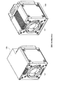
- FIG. 1 is an external perspective view showing the appearance (front side) of the housing
- FIG. 2 is an external perspective view showing the appearance (back side) of the housing.
- the present housing includes a front frame 3 that constitutes the front surface of the housing and to which an imaging lens is attached, a top frame 4 that constitutes the upper surface, and a bottom frame 5 that constitutes the bottom surface.
- a housing having a sealed structure including a rear frame 6 forming the back surface, a cover 7A forming the right side surface, and a cover 7B forming the left side surface.
- the right side surface indicates the right side surface when facing the front surface of the housing.
- a plurality of heat radiating fins 8 formed in a thin plate shape on the back surface of the housing and integrally formed with the heat radiating fins 8 to discharge air. 9 and are provided.
- the cooling fan 9 discharges the air sucked from the housing side to the outside (front side in FIG. 2). That is, in this housing, the cooling fan 9 is provided outside the housing, and by maintaining the sealed structure of the housing, it is possible to prevent dust from entering or diffusing into the housing. ..
- the heat radiation fin 8 includes two long fins connected to the left and right surfaces of the cooling fan 9, and a plurality of short fins provided between the long fins and connected to the upper surface or the lower surface of the cooling fan 9. ..
- Each fin is provided parallel to the side surface (covers 7A, 7B) of the present housing. That is, the heat radiation fins 8 are arranged so as to be parallel to the air flow formed by the duct described later.
- the width (length in the front-rear direction) of each fin is formed to be about the same as that of the cooling fan 9. Further, on the back surface of the present housing, a connector portion for connecting to various devices is provided in a portion where the heat radiation fin 8 and the cooling fan 9 are not provided.
- a plurality of grooves 41 are formed in the top frame 4 of this housing.
- a plurality of grooves 41 are formed in parallel in the direction connecting the front surface and the back surface of the housing.
- the surface area of the upper surface of the present housing is increased, and the air flow when the duct described later is attached is promoted to improve the cooling efficiency.
- a plurality of grooves similar to the grooves 41 of the top frame 4 are formed in the bottom frame 5 of the present housing in the direction connecting the front surface and the back surface.
- the front frame 3 is also formed with an upward groove 31 and a downward groove 32.
- FIG. 3 is an external perspective view showing the appearance (front side) of the image pickup apparatus
- FIG. 4 is an external perspective view showing the appearance (rear side) of the image pickup apparatus.
- the imaging device has a configuration in which ducts 10A and 10B are provided on the upper and lower surfaces of the housing shown in FIGS. 1 and 2. Even if the ducts 10A and 10B are attached, the size of the entire image pickup apparatus is not so different from that of the present housing, and does not hinder the miniaturization of the apparatus.
- the imaging apparatus includes a duct 10A that covers the top frame 4 of the housing and the upper part of the heat radiation fins 8, and a bottom frame 5 and the lower part of the heat radiation fins 8 of the housing. It is provided with a covering duct 10B.
- the duct 10A forms an air flow path from the front side to the cooling fan 9 on the back along the upper surface of the housing, and as shown in FIGS. 3 and 4, the top of the housing. It is mounted so as to cover the frame 4 and the heat radiation fins 8.
- the duct 10A includes an upper surface, a side surface, and a back surface, and the front surface and the lower surface are entirely openings. That is, no surface is formed on the front surface and the lower surface.
- the upper surface of the duct 10A is covered so that a gap is formed between the top frame 4 of the present housing and the upper portion of the heat radiation fins 8. It is not provided on the upper part of the connector part on the back side.
- the left side surface of the duct 10A is formed in an L shape so as to be in contact with the upper end portion of the cover 7B and the upper portion of the long fin at the right end (right end on the back surface) of the heat radiation fin 8. That is, no gap is formed between the left side surface of the duct 10A and the present housing.
- the right side surface of the duct 10A includes a surface in contact with the upper end portion of the cover 7A and a surface in contact with the upper part of the long fin at the left end of the heat radiation fin 8, and there is a gap between the right side surface of the duct 10A and the present housing. Is not formed.
- the length of the side surface of the duct 10A in the vertical direction (height direction) is appropriate so that a gap through which air serving as cooling air passes is formed between the upper surface of the duct 10A and the top frame 4 and the heat radiation fins 8. It is formed to the dimensions.
- the back surface of the duct 10A is a surface that is in contact with the upper part of the connector portion on the back surface of the present housing and a surface that is in contact with the rear end portion of the heat radiation fin 8 and covers the upper part of the long fin and the short fin of the heat radiation fin 8. And have.
- the back surface of the duct 10A is formed so that the air flowing over the top frame 4 passes between the heat radiation fins 8 and is sucked into the cooling fan 9.
- the duct 10A When the duct 10A is attached to the upper part of the housing, the front side of the housing and the upper part of the cooling fan 9 become openings, and between the duct 10A and the top frame 4, and the duct 10A and the upper part of the heat radiation fin 8. A gap is formed between the two. That is, the duct 10A forms a series of gaps that open to the front side, extend so as to cover the top frame 4 and the heat radiation fins 8, and open toward the cooling fan 9.
- the duct 10B forms an air flow path from the front side toward the cooling fan 9 on the back side along the lower surface of the housing, and as shown in FIGS. 3 and 4, the housing is present. It is attached so as to cover the lower side of the bottom frame 5 and the heat radiation fin 8. Since the duct 10B is formed in a shape substantially symmetrical with the duct 10A, detailed description thereof will be omitted.
- a gap is formed between the bottom frame 5 of the main housing and the duct 10B, and between the lower part of the heat radiation fin 8 and the duct 10B, and this gap is an air flow.
- air sucked from the front side of the image pickup apparatus flows along the bottom frame 5, passes between the heat radiation fins 8, and is exhausted from the cooling fan 9.
- FIG. 5 is a schematic explanatory view showing the flow of air around the housing when the duct is not provided.
- FIG. 5 is a schematic explanatory view showing the flow of air around the housing when the duct is not provided.
- the ducts 10A and 10B are not provided, forced air cooling is performed by the heat radiating fins 8 and the cooling fan 9 on the back side of the housing, and the radiating fins 8 on the upper side go toward the cooling fan 9.
- An air flow and an air flow from the lower heat radiation fin 8 to the cooling fan 9 are formed. As a result, heat is dissipated from the rear frame 6.
- FIG. 6 is a schematic explanatory view showing the flow of air around the housing when the duct is provided. As shown in FIG. 6, in the present imaging apparatus provided with ducts 10A and 10B above and below the housing, a flow of air that is taken in from the front side of the housing and exhausted from the cooling fan 9 on the back surface is generated.
- forced air cooling is realized by allowing air to flow between the top frame 4 and the duct 10A and between the bottom frame 5 and the duct 10B and exhausting the air from the cooling fan 9 via the heat radiation fins 8, and the top frame. It is possible to promote heat dissipation from the surfaces of the 4 and the bottom frame 5 and reduce the temperature inside the housing.
- FIG. 7 is a cross-sectional view of the image pickup apparatus.
- the present imaging apparatus includes a housing surrounded by the above-mentioned front frame 3, top frame 4, bottom frame 5, rear frame 6, covers 7A and 7B, and a housing as the configuration of the outer portion. It is provided with a heat radiation fin 8 and a cooling fan 9 provided on the back surface of the above, a duct 10A covering the upper part of the heat radiation fin 8 from the upper part of the top frame 4, and a duct 10B covering the lower part of the heat radiation fin 8 from the lower part of the bottom frame 5.
- the front frame 3 is provided with a lens mount 1 for attaching a lens (not shown).
- a prism 2 that decomposes light into the three primary colors
- image sensor 12A, 12B, 12C that captures the three primary colors decomposed by the prism 2
- an image sensor substrate that mounts the image sensors 12A, 12B, 12C, respectively. It is provided with an optical system such as 11A, 11B, 11C (image sensor substrate 11).
- the heat around the optical system is dissipated to the top frame 4 side, and the cooling fan 9 forms a flow from the front side to the back side in the gap between the top frame 4 and the duct 10A, and is discharged from the cooling fan 9. Is released by.
- the power supply board 13 on which a power supply element 14 for supplying power to each board is mounted, a signal processing board 15 on which a signal processing element 16 for processing a signal from the image pickup device board 11 is mounted, and the like.
- the power supply element 14 and the signal processing element 16 are elements that consume a large amount of power and become hot.
- the power element 14 is fixed to the bottom frame 5 via the heat radiating sheet 17A and dissipates heat to the bottom frame 5.
- the heat conducted to the bottom frame 5 is released to the outside air by the cooling fan 9 by actively flowing air between the duct 10B and the bottom frame 5 from the front side to the back side.
- the signal processing element 16 is attached to the rear frame 6 via the heat radiating sheet 17B so as to dissipate heat to the rear frame 6.
- the heat conducted to the rear frame 6 is cooled by forced air cooling by the heat radiation fins 8 and the cooling fan 9. In this way, the present imaging apparatus can efficiently dissipate the heat around the optical system and the heat of the element that becomes hot to the outside of the housing while keeping the housing in a sealed state.
- FIG. 8 is an external perspective view of another imaging device.
- the present imaging device described above has ducts on both the upper surface and the lower surface of the housing, but another imaging device has ducts on either surface.
- FIG. 8A shows a configuration in which the duct 10A is attached to the upper side of the housing
- FIG. 8B shows a configuration in which the duct 10B is attached to the lower side of the housing.
- the duct 10B is provided on the bottom frame 5 side as shown in FIG. 8 (b), and when the image pickup device is fixed on the lower surface, as shown in FIG. 8 (a).
- the duct 10A is arranged on the top frame 4 side.
- an air flow is formed from the front side to the back side on the surface provided with the duct 10A or 10B, and the air can be exhausted by the cooling fan 9.
- the inside of the housing can be cooled efficiently as compared with the configuration in which the duct is not provided.
- heat is dissipated from the upper surface or the lower surface of the housing to the fixed surface.
- a heat-dissipating fin 8 and a cooling fan 9 are provided on the back surface, and a housing having a sealed structure for accommodating an image pickup element inside and a housing having a closed structure and being attached to either the upper or lower sides or the upper or lower surfaces of the housing.
- the housing is provided with a duct 10A and / or a duct 10B that covers the mounting surface and the heat radiation fins 8 and forms a flow path for exhausting the air sucked from the front side of the housing from the cooling fan 9 on the back side.
- Air is actively flowed along both or one of the upper and lower surfaces of the housing while being kept in a sealed state, and forced air cooling is performed by the heat radiation fins 8 and the cooling fan 9, and the heat inside the housing is efficiently dissipated. At the same time, it has the effect of preventing dust from entering or spreading inside the housing.
- the heat radiation fins 8 are arranged so as to be parallel to the flow path of the air flowing through the ducts 10A and 10B, and the flow of air flowing from the front surface toward the cooling fan 9. This has the effect of promoting heat dissipation by the heat radiating fins 8 and efficiently cooling the housing without hindering the above.
- a plurality of grooves are formed in parallel on the surfaces (upper surface and / or lower surface) to which the ducts 10A and 10B are attached in the direction connecting the front surface and the back surface of the housing. This has the effect of increasing the surface area of the duct mounting surface and promoting the flow of air from the front surface to the cooling fan 9 to improve the cooling effect.
- a duct is provided on either the upper surface or the lower surface of the housing. Therefore, by appropriately attaching a duct according to the fixed position of the imaging device, dust can be collected in the housing. With a simple configuration, it has the effect of being able to cool the inside of the housing more efficiently than when there is no duct.
- the present invention is suitable for an imaging device capable of efficiently dissipating heat inside the housing while preventing dust from entering or diffusing inside the housing.
Landscapes
- Engineering & Computer Science (AREA)
- Physics & Mathematics (AREA)
- General Physics & Mathematics (AREA)
- Multimedia (AREA)
- Signal Processing (AREA)
- Aviation & Aerospace Engineering (AREA)
- Electromagnetism (AREA)
- Thermal Sciences (AREA)
- Microelectronics & Electronic Packaging (AREA)
- Studio Devices (AREA)
- Cooling Or The Like Of Electrical Apparatus (AREA)
- Cameras Adapted For Combination With Other Photographic Or Optical Apparatuses (AREA)
- Structure And Mechanism Of Cameras (AREA)
Priority Applications (1)
| Application Number | Priority Date | Filing Date | Title |
|---|---|---|---|
| JP2021556007A JP7111910B2 (ja) | 2019-11-11 | 2020-10-29 | 撮像装置 |
Applications Claiming Priority (2)
| Application Number | Priority Date | Filing Date | Title |
|---|---|---|---|
| JP2019-203736 | 2019-11-11 | ||
| JP2019203736 | 2019-11-11 |
Publications (1)
| Publication Number | Publication Date |
|---|---|
| WO2021095547A1 true WO2021095547A1 (ja) | 2021-05-20 |
Family
ID=75912304
Family Applications (1)
| Application Number | Title | Priority Date | Filing Date |
|---|---|---|---|
| PCT/JP2020/040631 Ceased WO2021095547A1 (ja) | 2019-11-11 | 2020-10-29 | 撮像装置 |
Country Status (2)
| Country | Link |
|---|---|
| JP (1) | JP7111910B2 (https=) |
| WO (1) | WO2021095547A1 (https=) |
Cited By (2)
| Publication number | Priority date | Publication date | Assignee | Title |
|---|---|---|---|---|
| KR20230153053A (ko) * | 2022-04-28 | 2023-11-06 | 주식회사 뷰웍스 | 영상촬영장치 냉각 구조 |
| WO2026058369A1 (ja) * | 2024-09-12 | 2026-03-19 | Astemo株式会社 | 撮像装置 |
Families Citing this family (2)
| Publication number | Priority date | Publication date | Assignee | Title |
|---|---|---|---|---|
| DE102013216452B4 (de) * | 2013-08-20 | 2016-12-01 | Sgl Carbon Se | Verbesserte Elektroden/Nippel-Verbindung |
| WO2025220369A1 (ja) * | 2024-04-16 | 2025-10-23 | 株式会社ニコン | 撮像装置 |
Citations (4)
| Publication number | Priority date | Publication date | Assignee | Title |
|---|---|---|---|---|
| JP2003230030A (ja) * | 2002-01-31 | 2003-08-15 | Hamamatsu Photonics Kk | 固体撮像装置 |
| JP2010041085A (ja) * | 2008-07-31 | 2010-02-18 | Hitachi Kokusai Electric Inc | カメラケース |
| JP2011141414A (ja) * | 2010-01-07 | 2011-07-21 | Hitachi Kokusai Electric Inc | 雲台一体型カメラ |
| JP2013175959A (ja) * | 2012-02-27 | 2013-09-05 | Nikon Corp | 電子カメラ及び冷却装置 |
-
2020
- 2020-10-29 WO PCT/JP2020/040631 patent/WO2021095547A1/ja not_active Ceased
- 2020-10-29 JP JP2021556007A patent/JP7111910B2/ja active Active
Patent Citations (4)
| Publication number | Priority date | Publication date | Assignee | Title |
|---|---|---|---|---|
| JP2003230030A (ja) * | 2002-01-31 | 2003-08-15 | Hamamatsu Photonics Kk | 固体撮像装置 |
| JP2010041085A (ja) * | 2008-07-31 | 2010-02-18 | Hitachi Kokusai Electric Inc | カメラケース |
| JP2011141414A (ja) * | 2010-01-07 | 2011-07-21 | Hitachi Kokusai Electric Inc | 雲台一体型カメラ |
| JP2013175959A (ja) * | 2012-02-27 | 2013-09-05 | Nikon Corp | 電子カメラ及び冷却装置 |
Cited By (3)
| Publication number | Priority date | Publication date | Assignee | Title |
|---|---|---|---|---|
| KR20230153053A (ko) * | 2022-04-28 | 2023-11-06 | 주식회사 뷰웍스 | 영상촬영장치 냉각 구조 |
| KR102730952B1 (ko) * | 2022-04-28 | 2024-11-15 | 주식회사 뷰웍스 | 영상촬영장치의 냉각장치 |
| WO2026058369A1 (ja) * | 2024-09-12 | 2026-03-19 | Astemo株式会社 | 撮像装置 |
Also Published As
| Publication number | Publication date |
|---|---|
| JP7111910B2 (ja) | 2022-08-02 |
| JPWO2021095547A1 (https=) | 2021-05-20 |
Similar Documents
| Publication | Publication Date | Title |
|---|---|---|
| JP7111910B2 (ja) | 撮像装置 | |
| KR101896569B1 (ko) | 반도체 모듈의 방열 장치 | |
| US10082850B2 (en) | Electronic device | |
| US11314154B2 (en) | Ducted cooling system of a camera | |
| JP5555084B2 (ja) | 光源装置 | |
| US7418995B2 (en) | System for cooling environmentally sealed enclosures | |
| WO2016143444A1 (ja) | 放送用ポータブルカメラ | |
| JP2012047798A (ja) | 電子機器 | |
| JP2022088679A (ja) | 遮光ケース | |
| JP2020057870A (ja) | 撮像装置 | |
| JP7313555B2 (ja) | 光照射装置 | |
| JP2002280779A (ja) | 電子機器の冷却装置 | |
| JP4269103B2 (ja) | 電気制御装置 | |
| JP4954625B2 (ja) | 監視カメラ | |
| JP2009206951A (ja) | 三板式カメラ | |
| JP2008015440A (ja) | ディスプレイ装置の冷却装置及び冷却方法 | |
| JP2012044300A (ja) | カメラケース | |
| KR102730952B1 (ko) | 영상촬영장치의 냉각장치 | |
| KR102784029B1 (ko) | 방열 효율이 개선된 이미지 프로젝션 장치 | |
| JP2023168933A (ja) | 撮像装置及び撮像素子ユニット | |
| JP2014187502A (ja) | 電子装置 | |
| JPH11330748A (ja) | 電子機器の放熱構造 | |
| JP2002329991A (ja) | 冷却構造を備える電子機器 | |
| CN223679516U (zh) | 光源装置的冷却结构及投影仪 | |
| JPH07226466A (ja) | 半導体素子の冷却装置 |
Legal Events
| Date | Code | Title | Description |
|---|---|---|---|
| 121 | Ep: the epo has been informed by wipo that ep was designated in this application |
Ref document number: 20888660 Country of ref document: EP Kind code of ref document: A1 |
|
| ENP | Entry into the national phase |
Ref document number: 2021556007 Country of ref document: JP Kind code of ref document: A |
|
| NENP | Non-entry into the national phase |
Ref country code: DE |
|
| 122 | Ep: pct application non-entry in european phase |
Ref document number: 20888660 Country of ref document: EP Kind code of ref document: A1 |