WO2021095547A1 - Imaging device - Google Patents
Imaging device Download PDFInfo
- Publication number
- WO2021095547A1 WO2021095547A1 PCT/JP2020/040631 JP2020040631W WO2021095547A1 WO 2021095547 A1 WO2021095547 A1 WO 2021095547A1 JP 2020040631 W JP2020040631 W JP 2020040631W WO 2021095547 A1 WO2021095547 A1 WO 2021095547A1
- Authority
- WO
- WIPO (PCT)
- Prior art keywords
- housing
- duct
- cooling fan
- imaging device
- heat
- Prior art date
Links
- 238000003384 imaging method Methods 0.000 title claims abstract description 41
- 238000001816 cooling Methods 0.000 claims abstract description 70
- 230000005855 radiation Effects 0.000 claims description 41
- 239000000428 dust Substances 0.000 abstract description 12
- 230000017525 heat dissipation Effects 0.000 abstract description 8
- 230000000694 effects Effects 0.000 description 10
- 230000001737 promoting effect Effects 0.000 description 4
- 230000003287 optical effect Effects 0.000 description 3
- 241001417523 Plesiopidae Species 0.000 description 2
- 239000003086 colorant Substances 0.000 description 2
- 239000000758 substrate Substances 0.000 description 2
- 238000007796 conventional method Methods 0.000 description 1
- 238000007599 discharging Methods 0.000 description 1
- 238000005516 engineering process Methods 0.000 description 1
- 238000004088 simulation Methods 0.000 description 1
- 238000003756 stirring Methods 0.000 description 1
- 238000002076 thermal analysis method Methods 0.000 description 1
Images


Classifications
-
- G—PHYSICS
- G03—PHOTOGRAPHY; CINEMATOGRAPHY; ANALOGOUS TECHNIQUES USING WAVES OTHER THAN OPTICAL WAVES; ELECTROGRAPHY; HOLOGRAPHY
- G03B—APPARATUS OR ARRANGEMENTS FOR TAKING PHOTOGRAPHS OR FOR PROJECTING OR VIEWING THEM; APPARATUS OR ARRANGEMENTS EMPLOYING ANALOGOUS TECHNIQUES USING WAVES OTHER THAN OPTICAL WAVES; ACCESSORIES THEREFOR
- G03B17/00—Details of cameras or camera bodies; Accessories therefor
- G03B17/55—Details of cameras or camera bodies; Accessories therefor with provision for heating or cooling, e.g. in aircraft
-
- H—ELECTRICITY
- H05—ELECTRIC TECHNIQUES NOT OTHERWISE PROVIDED FOR
- H05K—PRINTED CIRCUITS; CASINGS OR CONSTRUCTIONAL DETAILS OF ELECTRIC APPARATUS; MANUFACTURE OF ASSEMBLAGES OF ELECTRICAL COMPONENTS
- H05K7/00—Constructional details common to different types of electric apparatus
- H05K7/20—Modifications to facilitate cooling, ventilating, or heating
Definitions
- the present invention relates to a closed-type imaging device, and particularly relates to an imaging device capable of efficiently dissipating heat inside the housing while preventing dust from entering or diffusing into the housing.
- the image pickup device is provided with an image pickup element inside the housing, and has a sealed structure in order to prevent dust and dirt from entering the inside of the housing.
- the number of pixels of the image sensor used in the image sensor is increasing year by year, the power consumption of the image sensor itself is increasing, and the need for cooling the image sensor is increasing.
- Patent Document 1 describes that a cooling fan takes in outside air from the outside into the housing and discharges it into the housing for cooling.
- Patent Document 2 describes that a cooling fan is installed inside a closed housing to stir and cool the internal atmosphere.
- the conventional cooling method of the imaging device has a problem that dust is allowed to enter the inside of the housing when the outside air is taken in, or the dust is diffused inside the housing by the cooling fan.
- Patent Document 1 and Patent Document 2 do not describe that a cooling fan is provided on the back surface outside the housing and is provided with a duct that forms an air flow path from the front surface of the housing toward the cooling fan.
- the present invention has been made in view of the above circumstances, and an object of the present invention is to provide an imaging device capable of efficiently dissipating heat inside a housing while preventing dust from entering or diffusing inside the housing. And.
- the present invention for solving the problems of the above-mentioned conventional example is an imaging device in which an imaging element is housed inside a sealed housing, and the housing is provided with a lens mount to which a lens is attached to the front surface, and the housing is provided with a lens mount. It has a heat radiation fin that emits heat and a cooling fan that cools the heat radiation fin on the back surface, and is attached to the upper or lower surface of the housing, opens at the front surface of the housing, and covers the mounting surface and the heat radiation fin.
- a gap is formed so as to open to the cooling fan, and a duct that does not open is provided on the side surface of the housing, and the heat radiation fins are sucked from the front side of the duct and discharged by the cooling fan through the gap. It is characterized in that it is arranged so as to be parallel to the air flow path.
- the present invention is characterized in that, in the above-mentioned imaging device, ducts are attached to both the upper surface and the lower surface of the housing.
- the present invention is characterized in that, in the above-mentioned imaging device, a plurality of grooves are formed on the mounting surface of the duct in the housing in the direction connecting the front surface and the back surface.
- the imaging device is an imaging device in which an imaging element is housed inside a sealed housing.
- the housing is provided with a lens mount to which a lens is attached to the front surface, and heat-dissipating fins that emit heat to the back surface.
- a cooling fan for cooling the heat radiation fins which is attached to the upper surface or the lower surface of the housing, opens at the front surface of the housing, extends so as to cover the mounting surface and the heat radiation fins, and opens to the cooling fan.
- a duct that does not open on the side of the housing is provided so that the heat radiation fins are parallel to the air flow path that is sucked in from the front side of the duct and discharged through the gap by the cooling fan.
- the image pickup device Since the image pickup device is arranged, it prevents dust from entering the inside of the housing and forms a flow of air flowing from the front side of the housing toward the cooling fan along the mounting surface of the duct. It has the effect of promoting heat dissipation not only from the back surface but also from the duct mounting surface to efficiently cool the inside of the housing.
- the image pickup device in the housing, has a plurality of grooves formed in the direction connecting the front surface and the back surface on the mounting surface of the duct, so that the surface area of the mounting surface is increased for air cooling. It has the effect of improving the effect, promoting the flow of air from the front to the back, and cooling the inside of the housing more efficiently.
- the image pickup device (the present image pickup device) according to the embodiment of the present invention is provided with a heat radiation fin and a cooling fan on the back surface, and has a closed structure housing for accommodating the image pickup element inside, and the upper and lower sides or upper and lower sides of the housing. It is mounted on one of the surfaces, covers the mounting surface and the heat radiation fins, and is provided with a duct that forms a flow path for discharging the air sucked from the front side of the housing from the cooling fan on the back side.
- a plurality of grooves are formed in the direction connecting the front surface and the back surface of the housing on either the upper and lower sides or the upper and lower surfaces of the housing provided with the duct. It is possible to increase the surface area of the housing and promote the flow of air from the front to the back along the groove to efficiently cool the housing.
- FIG. 1 is an external perspective view showing the appearance (front side) of the housing
- FIG. 2 is an external perspective view showing the appearance (back side) of the housing.
- the present housing includes a front frame 3 that constitutes the front surface of the housing and to which an imaging lens is attached, a top frame 4 that constitutes the upper surface, and a bottom frame 5 that constitutes the bottom surface.
- a housing having a sealed structure including a rear frame 6 forming the back surface, a cover 7A forming the right side surface, and a cover 7B forming the left side surface.
- the right side surface indicates the right side surface when facing the front surface of the housing.
- a plurality of heat radiating fins 8 formed in a thin plate shape on the back surface of the housing and integrally formed with the heat radiating fins 8 to discharge air. 9 and are provided.
- the cooling fan 9 discharges the air sucked from the housing side to the outside (front side in FIG. 2). That is, in this housing, the cooling fan 9 is provided outside the housing, and by maintaining the sealed structure of the housing, it is possible to prevent dust from entering or diffusing into the housing. ..
- the heat radiation fin 8 includes two long fins connected to the left and right surfaces of the cooling fan 9, and a plurality of short fins provided between the long fins and connected to the upper surface or the lower surface of the cooling fan 9. ..
- Each fin is provided parallel to the side surface (covers 7A, 7B) of the present housing. That is, the heat radiation fins 8 are arranged so as to be parallel to the air flow formed by the duct described later.
- the width (length in the front-rear direction) of each fin is formed to be about the same as that of the cooling fan 9. Further, on the back surface of the present housing, a connector portion for connecting to various devices is provided in a portion where the heat radiation fin 8 and the cooling fan 9 are not provided.
- a plurality of grooves 41 are formed in the top frame 4 of this housing.
- a plurality of grooves 41 are formed in parallel in the direction connecting the front surface and the back surface of the housing.
- the surface area of the upper surface of the present housing is increased, and the air flow when the duct described later is attached is promoted to improve the cooling efficiency.
- a plurality of grooves similar to the grooves 41 of the top frame 4 are formed in the bottom frame 5 of the present housing in the direction connecting the front surface and the back surface.
- the front frame 3 is also formed with an upward groove 31 and a downward groove 32.
- FIG. 3 is an external perspective view showing the appearance (front side) of the image pickup apparatus
- FIG. 4 is an external perspective view showing the appearance (rear side) of the image pickup apparatus.
- the imaging device has a configuration in which ducts 10A and 10B are provided on the upper and lower surfaces of the housing shown in FIGS. 1 and 2. Even if the ducts 10A and 10B are attached, the size of the entire image pickup apparatus is not so different from that of the present housing, and does not hinder the miniaturization of the apparatus.
- the imaging apparatus includes a duct 10A that covers the top frame 4 of the housing and the upper part of the heat radiation fins 8, and a bottom frame 5 and the lower part of the heat radiation fins 8 of the housing. It is provided with a covering duct 10B.
- the duct 10A forms an air flow path from the front side to the cooling fan 9 on the back along the upper surface of the housing, and as shown in FIGS. 3 and 4, the top of the housing. It is mounted so as to cover the frame 4 and the heat radiation fins 8.
- the duct 10A includes an upper surface, a side surface, and a back surface, and the front surface and the lower surface are entirely openings. That is, no surface is formed on the front surface and the lower surface.
- the upper surface of the duct 10A is covered so that a gap is formed between the top frame 4 of the present housing and the upper portion of the heat radiation fins 8. It is not provided on the upper part of the connector part on the back side.
- the left side surface of the duct 10A is formed in an L shape so as to be in contact with the upper end portion of the cover 7B and the upper portion of the long fin at the right end (right end on the back surface) of the heat radiation fin 8. That is, no gap is formed between the left side surface of the duct 10A and the present housing.
- the right side surface of the duct 10A includes a surface in contact with the upper end portion of the cover 7A and a surface in contact with the upper part of the long fin at the left end of the heat radiation fin 8, and there is a gap between the right side surface of the duct 10A and the present housing. Is not formed.
- the length of the side surface of the duct 10A in the vertical direction (height direction) is appropriate so that a gap through which air serving as cooling air passes is formed between the upper surface of the duct 10A and the top frame 4 and the heat radiation fins 8. It is formed to the dimensions.
- the back surface of the duct 10A is a surface that is in contact with the upper part of the connector portion on the back surface of the present housing and a surface that is in contact with the rear end portion of the heat radiation fin 8 and covers the upper part of the long fin and the short fin of the heat radiation fin 8. And have.
- the back surface of the duct 10A is formed so that the air flowing over the top frame 4 passes between the heat radiation fins 8 and is sucked into the cooling fan 9.
- the duct 10A When the duct 10A is attached to the upper part of the housing, the front side of the housing and the upper part of the cooling fan 9 become openings, and between the duct 10A and the top frame 4, and the duct 10A and the upper part of the heat radiation fin 8. A gap is formed between the two. That is, the duct 10A forms a series of gaps that open to the front side, extend so as to cover the top frame 4 and the heat radiation fins 8, and open toward the cooling fan 9.
- the duct 10B forms an air flow path from the front side toward the cooling fan 9 on the back side along the lower surface of the housing, and as shown in FIGS. 3 and 4, the housing is present. It is attached so as to cover the lower side of the bottom frame 5 and the heat radiation fin 8. Since the duct 10B is formed in a shape substantially symmetrical with the duct 10A, detailed description thereof will be omitted.
- a gap is formed between the bottom frame 5 of the main housing and the duct 10B, and between the lower part of the heat radiation fin 8 and the duct 10B, and this gap is an air flow.
- air sucked from the front side of the image pickup apparatus flows along the bottom frame 5, passes between the heat radiation fins 8, and is exhausted from the cooling fan 9.
- FIG. 5 is a schematic explanatory view showing the flow of air around the housing when the duct is not provided.
- FIG. 5 is a schematic explanatory view showing the flow of air around the housing when the duct is not provided.
- the ducts 10A and 10B are not provided, forced air cooling is performed by the heat radiating fins 8 and the cooling fan 9 on the back side of the housing, and the radiating fins 8 on the upper side go toward the cooling fan 9.
- An air flow and an air flow from the lower heat radiation fin 8 to the cooling fan 9 are formed. As a result, heat is dissipated from the rear frame 6.
- FIG. 6 is a schematic explanatory view showing the flow of air around the housing when the duct is provided. As shown in FIG. 6, in the present imaging apparatus provided with ducts 10A and 10B above and below the housing, a flow of air that is taken in from the front side of the housing and exhausted from the cooling fan 9 on the back surface is generated.
- forced air cooling is realized by allowing air to flow between the top frame 4 and the duct 10A and between the bottom frame 5 and the duct 10B and exhausting the air from the cooling fan 9 via the heat radiation fins 8, and the top frame. It is possible to promote heat dissipation from the surfaces of the 4 and the bottom frame 5 and reduce the temperature inside the housing.
- FIG. 7 is a cross-sectional view of the image pickup apparatus.
- the present imaging apparatus includes a housing surrounded by the above-mentioned front frame 3, top frame 4, bottom frame 5, rear frame 6, covers 7A and 7B, and a housing as the configuration of the outer portion. It is provided with a heat radiation fin 8 and a cooling fan 9 provided on the back surface of the above, a duct 10A covering the upper part of the heat radiation fin 8 from the upper part of the top frame 4, and a duct 10B covering the lower part of the heat radiation fin 8 from the lower part of the bottom frame 5.
- the front frame 3 is provided with a lens mount 1 for attaching a lens (not shown).
- a prism 2 that decomposes light into the three primary colors
- image sensor 12A, 12B, 12C that captures the three primary colors decomposed by the prism 2
- an image sensor substrate that mounts the image sensors 12A, 12B, 12C, respectively. It is provided with an optical system such as 11A, 11B, 11C (image sensor substrate 11).
- the heat around the optical system is dissipated to the top frame 4 side, and the cooling fan 9 forms a flow from the front side to the back side in the gap between the top frame 4 and the duct 10A, and is discharged from the cooling fan 9. Is released by.
- the power supply board 13 on which a power supply element 14 for supplying power to each board is mounted, a signal processing board 15 on which a signal processing element 16 for processing a signal from the image pickup device board 11 is mounted, and the like.
- the power supply element 14 and the signal processing element 16 are elements that consume a large amount of power and become hot.
- the power element 14 is fixed to the bottom frame 5 via the heat radiating sheet 17A and dissipates heat to the bottom frame 5.
- the heat conducted to the bottom frame 5 is released to the outside air by the cooling fan 9 by actively flowing air between the duct 10B and the bottom frame 5 from the front side to the back side.
- the signal processing element 16 is attached to the rear frame 6 via the heat radiating sheet 17B so as to dissipate heat to the rear frame 6.
- the heat conducted to the rear frame 6 is cooled by forced air cooling by the heat radiation fins 8 and the cooling fan 9. In this way, the present imaging apparatus can efficiently dissipate the heat around the optical system and the heat of the element that becomes hot to the outside of the housing while keeping the housing in a sealed state.
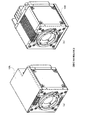
- FIG. 8 is an external perspective view of another imaging device.
- the present imaging device described above has ducts on both the upper surface and the lower surface of the housing, but another imaging device has ducts on either surface.
- FIG. 8A shows a configuration in which the duct 10A is attached to the upper side of the housing
- FIG. 8B shows a configuration in which the duct 10B is attached to the lower side of the housing.
- the duct 10B is provided on the bottom frame 5 side as shown in FIG. 8 (b), and when the image pickup device is fixed on the lower surface, as shown in FIG. 8 (a).
- the duct 10A is arranged on the top frame 4 side.
- an air flow is formed from the front side to the back side on the surface provided with the duct 10A or 10B, and the air can be exhausted by the cooling fan 9.
- the inside of the housing can be cooled efficiently as compared with the configuration in which the duct is not provided.
- heat is dissipated from the upper surface or the lower surface of the housing to the fixed surface.
- a heat-dissipating fin 8 and a cooling fan 9 are provided on the back surface, and a housing having a sealed structure for accommodating an image pickup element inside and a housing having a closed structure and being attached to either the upper or lower sides or the upper or lower surfaces of the housing.
- the housing is provided with a duct 10A and / or a duct 10B that covers the mounting surface and the heat radiation fins 8 and forms a flow path for exhausting the air sucked from the front side of the housing from the cooling fan 9 on the back side.
- Air is actively flowed along both or one of the upper and lower surfaces of the housing while being kept in a sealed state, and forced air cooling is performed by the heat radiation fins 8 and the cooling fan 9, and the heat inside the housing is efficiently dissipated. At the same time, it has the effect of preventing dust from entering or spreading inside the housing.
- the heat radiation fins 8 are arranged so as to be parallel to the flow path of the air flowing through the ducts 10A and 10B, and the flow of air flowing from the front surface toward the cooling fan 9. This has the effect of promoting heat dissipation by the heat radiating fins 8 and efficiently cooling the housing without hindering the above.
- a plurality of grooves are formed in parallel on the surfaces (upper surface and / or lower surface) to which the ducts 10A and 10B are attached in the direction connecting the front surface and the back surface of the housing. This has the effect of increasing the surface area of the duct mounting surface and promoting the flow of air from the front surface to the cooling fan 9 to improve the cooling effect.
- a duct is provided on either the upper surface or the lower surface of the housing. Therefore, by appropriately attaching a duct according to the fixed position of the imaging device, dust can be collected in the housing. With a simple configuration, it has the effect of being able to cool the inside of the housing more efficiently than when there is no duct.
- the present invention is suitable for an imaging device capable of efficiently dissipating heat inside the housing while preventing dust from entering or diffusing inside the housing.
Landscapes
- Engineering & Computer Science (AREA)
- Physics & Mathematics (AREA)
- Aviation & Aerospace Engineering (AREA)
- General Physics & Mathematics (AREA)
- Thermal Sciences (AREA)
- Microelectronics & Electronic Packaging (AREA)
- Studio Devices (AREA)
- Cooling Or The Like Of Electrical Apparatus (AREA)
Abstract
[Problem] To provide an imaging device that prevents dust from entering and being diffused inside of a housing while making it possible to efficiently dissipate the heat inside of the housing. [Solution] An imaging device provided with: a housing including heat dissipation fins 8 and a cooling fan 9 on the back surface thereof and having a sealed structure inside of which an imaging element is accommodated; and ducts 10A and/or 10B that are attached to both or one of the upper and lower surfaces of the housing, that open at the front surface of the housing and do not open on the side surfaces of the housing, that extend so as to cover an attachment surface and the heat dissipation fins 8, and that have a gap formed therein opening into the cooling fan 9. The heat dissipation fins 8 are arranged so as to be parallel to a flow path for air taken in from the front surface side of the ducts and discharged from the cooling fan 9.
Description
本発明は、密閉型の撮像装置に係り、特に筐体内部への塵埃の侵入や拡散を防ぎつつ、筐体内部の熱を効率的に放熱することができる撮像装置に関する。
The present invention relates to a closed-type imaging device, and particularly relates to an imaging device capable of efficiently dissipating heat inside the housing while preventing dust from entering or diffusing into the housing.
[先行技術の説明]
撮像装置は、撮像素子を筐体内部に備えており、筐体内部へのゴミや塵埃の侵入を防ぐために、密閉構造としたものがある。
撮像装置で使用する撮像素子は年々高画素化が進み、撮像素子自体の消費電力が増加しており、撮像素子冷却の必要性が増している。 [Explanation of prior art]
The image pickup device is provided with an image pickup element inside the housing, and has a sealed structure in order to prevent dust and dirt from entering the inside of the housing.
The number of pixels of the image sensor used in the image sensor is increasing year by year, the power consumption of the image sensor itself is increasing, and the need for cooling the image sensor is increasing.
[関連技術]
撮像装置内部を冷却する従来技術としては、特許第6112745号公報「電子装置」(特許文献1)、特許第6552054号公報「3板式固体撮像装置の冷却装置」(特許文献2)がある。
特許文献1には、冷却ファンで外部から筐体内部に外気を取り込み、筐体内部に吐き出すことで冷却することが記載されている。
特許文献2には、密閉した筐体内部に冷却ファンを設置し、内部雰囲気を撹拌させて冷却することが記載されている。 [Related technology]
Conventional techniques for cooling the inside of an image pickup apparatus include Patent No. 6112745 “Electronic device” (Patent Document 1) and Patent No. 6552054 “Cooling device for a three-plate solid-state image pickup device” (Patent Document 2).
Patent Document 1 describes that a cooling fan takes in outside air from the outside into the housing and discharges it into the housing for cooling.
Patent Document 2 describes that a cooling fan is installed inside a closed housing to stir and cool the internal atmosphere.
撮像装置内部を冷却する従来技術としては、特許第6112745号公報「電子装置」(特許文献1)、特許第6552054号公報「3板式固体撮像装置の冷却装置」(特許文献2)がある。
特許文献1には、冷却ファンで外部から筐体内部に外気を取り込み、筐体内部に吐き出すことで冷却することが記載されている。
特許文献2には、密閉した筐体内部に冷却ファンを設置し、内部雰囲気を撹拌させて冷却することが記載されている。 [Related technology]
Conventional techniques for cooling the inside of an image pickup apparatus include Patent No. 6112745 “Electronic device” (Patent Document 1) and Patent No. 6552054 “Cooling device for a three-plate solid-state image pickup device” (Patent Document 2).
Patent Document 1 describes that a cooling fan takes in outside air from the outside into the housing and discharges it into the housing for cooling.
しかしながら、従来の撮像装置の冷却方法では、外気を取り込む際に塵埃を筐体内部に侵入させたり、冷却ファンにより塵埃を筐体内で拡散させてしまうという問題点があった。
However, the conventional cooling method of the imaging device has a problem that dust is allowed to enter the inside of the housing when the outside air is taken in, or the dust is diffused inside the housing by the cooling fan.
尚、特許文献1及び特許文献2には、冷却ファンを筐体外部の背面に設け、筐体の前面から冷却ファンに向かって空気の流路を形成するダクトを備えることは記載されていない。
Note that Patent Document 1 and Patent Document 2 do not describe that a cooling fan is provided on the back surface outside the housing and is provided with a duct that forms an air flow path from the front surface of the housing toward the cooling fan.
本発明は上記実状に鑑みて為されたもので、筐体内部への塵埃の侵入や拡散を防ぎつつ、筐体内部の熱を効率的に放熱することができる撮像装置を提供することを目的とする。
The present invention has been made in view of the above circumstances, and an object of the present invention is to provide an imaging device capable of efficiently dissipating heat inside a housing while preventing dust from entering or diffusing inside the housing. And.
上記従来例の問題点を解決するための本発明は、密閉された筐体の内部に撮像素子を収納した撮像装置であって、筐体は、前面にレンズが取り付けられるレンズマウントを備えると共に、背面に、熱を放出する放熱フィンと、放熱フィンを冷却する冷却ファンとを有し、筐体の上面又は下面に取り付けられ、筐体の前面で開口し、取り付け面と放熱フィンとを覆うように延びて、冷却ファンに開口するよう隙間が形成されると共に、筐体の側面に開口しないダクトを備え、放熱フィンが、ダクトの前面側から吸入されて隙間を通って冷却ファンによって排出される空気の流路と平行になるよう配置されていることを特徴としている。
The present invention for solving the problems of the above-mentioned conventional example is an imaging device in which an imaging element is housed inside a sealed housing, and the housing is provided with a lens mount to which a lens is attached to the front surface, and the housing is provided with a lens mount. It has a heat radiation fin that emits heat and a cooling fan that cools the heat radiation fin on the back surface, and is attached to the upper or lower surface of the housing, opens at the front surface of the housing, and covers the mounting surface and the heat radiation fin. A gap is formed so as to open to the cooling fan, and a duct that does not open is provided on the side surface of the housing, and the heat radiation fins are sucked from the front side of the duct and discharged by the cooling fan through the gap. It is characterized in that it is arranged so as to be parallel to the air flow path.
また、本発明は、上記撮像装置において、ダクトが、筐体の上面及び下面の双方に取り付けられたことを特徴としている。
Further, the present invention is characterized in that, in the above-mentioned imaging device, ducts are attached to both the upper surface and the lower surface of the housing.
また、本発明は、上記撮像装置において、筐体において、ダクトの取り付け面に、前面と背面とを結ぶ方向に複数の溝が形成されていることを特徴としている。
Further, the present invention is characterized in that, in the above-mentioned imaging device, a plurality of grooves are formed on the mounting surface of the duct in the housing in the direction connecting the front surface and the back surface.
本発明によれば、密閉された筐体の内部に撮像素子を収納した撮像装置であって、筐体は、前面にレンズが取り付けられるレンズマウントを備えると共に、背面に、熱を放出する放熱フィンと、放熱フィンを冷却する冷却ファンとを有し、筐体の上面又は下面に取り付けられ、筐体の前面で開口し、取り付け面と放熱フィンとを覆うように延びて、冷却ファンに開口するよう隙間が形成されると共に、筐体の側面に開口しないダクトを備え、放熱フィンが、ダクトの前面側から吸入されて隙間を通って冷却ファンによって排出される空気の流路と平行になるよう配置されている撮像装置としているので、筐体内部に塵埃が侵入するのを防ぐと共に、筐体の前面側からダクトの取り付け面に沿って冷却ファンに向かって流れる空気の流れを形成して、背面だけでなくダクト取り付け面からの放熱を促進して筐体内部を効率的に冷却することができる効果がある。
According to the present invention, the imaging device is an imaging device in which an imaging element is housed inside a sealed housing. The housing is provided with a lens mount to which a lens is attached to the front surface, and heat-dissipating fins that emit heat to the back surface. And a cooling fan for cooling the heat radiation fins, which is attached to the upper surface or the lower surface of the housing, opens at the front surface of the housing, extends so as to cover the mounting surface and the heat radiation fins, and opens to the cooling fan. A duct that does not open on the side of the housing is provided so that the heat radiation fins are parallel to the air flow path that is sucked in from the front side of the duct and discharged through the gap by the cooling fan. Since the image pickup device is arranged, it prevents dust from entering the inside of the housing and forms a flow of air flowing from the front side of the housing toward the cooling fan along the mounting surface of the duct. It has the effect of promoting heat dissipation not only from the back surface but also from the duct mounting surface to efficiently cool the inside of the housing.
また、本発明によれば、筐体において、ダクトの取り付け面に、前面と背面とを結ぶ方向に複数の溝が形成されている上記撮像装置としているので、取り付け面表面積を増大させて空冷の効果を向上させ、前面から背面に向かう空気の流れを促進して更に効率的に筐体内部を冷却することができる効果がある。
Further, according to the present invention, in the housing, the image pickup device has a plurality of grooves formed in the direction connecting the front surface and the back surface on the mounting surface of the duct, so that the surface area of the mounting surface is increased for air cooling. It has the effect of improving the effect, promoting the flow of air from the front to the back, and cooling the inside of the housing more efficiently.
本発明の実施の形態について図面を参照しながら説明する。
[実施の形態の概要]
本発明の実施の形態に係る撮像装置(本撮像装置)は、背面に放熱フィンと冷却ファンとを備え、内部に撮像素子を収納する密閉構造の筐体と、当該筐体の上下両面若しくは上下のいずれか一方の面に取り付けられ、取り付け面と放熱フィンとを覆い、筐体前面側から吸入した空気を背面の冷却ファンから排出する流路を形成するダクトとを備えたものであり、筐体を密閉状態に保ったまま、筐体の上下面の両方又は一方に沿って空気を効率的に流して、放熱フィン及び冷却ファンで強制空冷し、筐体内部の熱を放熱することができ、塵埃が筐体内部に侵入したり、拡散するのを防ぐことができるものである。 Embodiments of the present invention will be described with reference to the drawings.
[Outline of Embodiment]
The image pickup device (the present image pickup device) according to the embodiment of the present invention is provided with a heat radiation fin and a cooling fan on the back surface, and has a closed structure housing for accommodating the image pickup element inside, and the upper and lower sides or upper and lower sides of the housing. It is mounted on one of the surfaces, covers the mounting surface and the heat radiation fins, and is provided with a duct that forms a flow path for discharging the air sucked from the front side of the housing from the cooling fan on the back side. While keeping the body in a sealed state, air can be efficiently flowed along both or one of the upper and lower surfaces of the housing, and forced air cooling is performed by the heat radiation fins and the cooling fan to dissipate the heat inside the housing. , It is possible to prevent dust from entering or spreading inside the housing.
また、本撮像装置は、ダクトが設けられた筐体の上下両面又は上下のいずれか一方の面に、筐体の前面と背面とを結ぶ方向に複数の溝が形成されているものであり、筐体の表面積を増大させると共に、溝に沿って前面から背面に向かう空気の流れを促進して、効率的に冷却することができるものである。
Further, in this imaging device, a plurality of grooves are formed in the direction connecting the front surface and the back surface of the housing on either the upper and lower sides or the upper and lower surfaces of the housing provided with the duct. It is possible to increase the surface area of the housing and promote the flow of air from the front to the back along the groove to efficiently cool the housing.
[本撮像装置の筐体外観:図1,図2]
まず、本撮像装置の筐体(本筐体)の構成について図1,図2を用いて説明する。図1は、本筐体の外観(前面側)を示す外観斜視図であり、図2は、本筐体の外観(背面側)を示す外観斜視図である。
図1,図2に示すように、本筐体は、筐体の前面を構成し、撮像レンズが取り付けられるフロントフレーム3と、上面を構成するトップフレーム4と、底面を構成するボトムフレーム5と、背面を構成するリアフレーム6と、右側面を構成するカバー7Aと、左側面を構成するカバー7Bとを備えた密閉構造の筐体である。尚、右側面は、筐体の正面に正対した際に向かって右側の側面を示す。 [Appearance of the housing of this imaging device: FIGS. 1 and 2]
First, the configuration of the housing (this housing) of the image pickup apparatus will be described with reference to FIGS. 1 and 2. FIG. 1 is an external perspective view showing the appearance (front side) of the housing, and FIG. 2 is an external perspective view showing the appearance (back side) of the housing.
As shown in FIGS. 1 and 2, the present housing includes afront frame 3 that constitutes the front surface of the housing and to which an imaging lens is attached, a top frame 4 that constitutes the upper surface, and a bottom frame 5 that constitutes the bottom surface. , A housing having a sealed structure including a rear frame 6 forming the back surface, a cover 7A forming the right side surface, and a cover 7B forming the left side surface. The right side surface indicates the right side surface when facing the front surface of the housing.
まず、本撮像装置の筐体(本筐体)の構成について図1,図2を用いて説明する。図1は、本筐体の外観(前面側)を示す外観斜視図であり、図2は、本筐体の外観(背面側)を示す外観斜視図である。
図1,図2に示すように、本筐体は、筐体の前面を構成し、撮像レンズが取り付けられるフロントフレーム3と、上面を構成するトップフレーム4と、底面を構成するボトムフレーム5と、背面を構成するリアフレーム6と、右側面を構成するカバー7Aと、左側面を構成するカバー7Bとを備えた密閉構造の筐体である。尚、右側面は、筐体の正面に正対した際に向かって右側の側面を示す。 [Appearance of the housing of this imaging device: FIGS. 1 and 2]
First, the configuration of the housing (this housing) of the image pickup apparatus will be described with reference to FIGS. 1 and 2. FIG. 1 is an external perspective view showing the appearance (front side) of the housing, and FIG. 2 is an external perspective view showing the appearance (back side) of the housing.
As shown in FIGS. 1 and 2, the present housing includes a
そして、図2に示すように、本筐体の背面には、薄い板状に形成され、熱を放出する複数の放熱フィン8と、放熱フィン8と一体に形成され、空気を排出する冷却ファン9とが設けられている。冷却ファン9は、筐体側から吸入した空気を外側(図2の手前側)に排出する。
つまり、本筐体では、冷却ファン9は筐体の外部に設けられており、筐体の密閉構造を保持することにより、筐体内部への塵埃の侵入や拡散を防ぐことができるものである。 Then, as shown in FIG. 2, a plurality ofheat radiating fins 8 formed in a thin plate shape on the back surface of the housing and integrally formed with the heat radiating fins 8 to discharge air. 9 and are provided. The cooling fan 9 discharges the air sucked from the housing side to the outside (front side in FIG. 2).
That is, in this housing, thecooling fan 9 is provided outside the housing, and by maintaining the sealed structure of the housing, it is possible to prevent dust from entering or diffusing into the housing. ..
つまり、本筐体では、冷却ファン9は筐体の外部に設けられており、筐体の密閉構造を保持することにより、筐体内部への塵埃の侵入や拡散を防ぐことができるものである。 Then, as shown in FIG. 2, a plurality of
That is, in this housing, the
放熱フィン8は、冷却ファン9の左右の面にそれぞれ接続する2枚の長いフィンと、長いフィンの間に設けられ、冷却ファン9の上面又は下面に接続する複数の短いフィンとを備えている。各フィンは、本筐体の側面(カバー7A,7B)に平行に設けられている。つまり、放熱フィン8は、後述するダクトによって形成される空気の流れと平行になるような向きに配置されているものである。
各フィンの幅(前後方向の長さ)は、冷却ファン9と同程度に形成されている。
また、本筐体の背面において、放熱フィン8及び冷却ファン9が設けられていない部分に、各種装置と接続されるコネクタ部が設けられている。 Theheat radiation fin 8 includes two long fins connected to the left and right surfaces of the cooling fan 9, and a plurality of short fins provided between the long fins and connected to the upper surface or the lower surface of the cooling fan 9. .. Each fin is provided parallel to the side surface (covers 7A, 7B) of the present housing. That is, the heat radiation fins 8 are arranged so as to be parallel to the air flow formed by the duct described later.
The width (length in the front-rear direction) of each fin is formed to be about the same as that of thecooling fan 9.
Further, on the back surface of the present housing, a connector portion for connecting to various devices is provided in a portion where theheat radiation fin 8 and the cooling fan 9 are not provided.
各フィンの幅(前後方向の長さ)は、冷却ファン9と同程度に形成されている。
また、本筐体の背面において、放熱フィン8及び冷却ファン9が設けられていない部分に、各種装置と接続されるコネクタ部が設けられている。 The
The width (length in the front-rear direction) of each fin is formed to be about the same as that of the
Further, on the back surface of the present housing, a connector portion for connecting to various devices is provided in a portion where the
更に、本筐体のトップフレーム4には、複数の溝41が形成されている。溝41は、筐体の前面と背面とを結ぶ方向に、複数平行に形成されている。
溝41が形成されることにより、本筐体の上面の表面積を増大させると共に、後述するダクトを取り付けた場合の空気の流れを促進して、冷却効率を向上させるものである。
また、図1,2では示されていないが、本筐体のボトムフレーム5にも、トップフレーム4の溝41と同様の複数の溝が前面と背面とを結ぶ方向に形成されている。
フロントフレーム3にも、上方向に向かう溝31、及び下方向に向かう溝32が形成されている。 Further, a plurality ofgrooves 41 are formed in the top frame 4 of this housing. A plurality of grooves 41 are formed in parallel in the direction connecting the front surface and the back surface of the housing.
By forming thegroove 41, the surface area of the upper surface of the present housing is increased, and the air flow when the duct described later is attached is promoted to improve the cooling efficiency.
Further, although not shown in FIGS. 1 and 2, a plurality of grooves similar to thegrooves 41 of the top frame 4 are formed in the bottom frame 5 of the present housing in the direction connecting the front surface and the back surface.
Thefront frame 3 is also formed with an upward groove 31 and a downward groove 32.
溝41が形成されることにより、本筐体の上面の表面積を増大させると共に、後述するダクトを取り付けた場合の空気の流れを促進して、冷却効率を向上させるものである。
また、図1,2では示されていないが、本筐体のボトムフレーム5にも、トップフレーム4の溝41と同様の複数の溝が前面と背面とを結ぶ方向に形成されている。
フロントフレーム3にも、上方向に向かう溝31、及び下方向に向かう溝32が形成されている。 Further, a plurality of
By forming the
Further, although not shown in FIGS. 1 and 2, a plurality of grooves similar to the
The
[本撮像装置の外観:図3,図4]
次に、本撮像装置の構成について図3,図4を用いて説明する。図3は、本撮像装置の外観(前面側)を示す外観斜視図であり、図4は、本撮像装置の外観(背面側)を示す外観斜視図である。
図3,図4に示すように、本撮像装置は、図1,2に示した本筐体の上下面にダクト10A,10Bを備えた構成である。
ダクト10A,10Bを取り付けても、本撮像装置全体の大きさは本筐体とそれほど変わらず、装置の小型化を妨げるものではない。 [Appearance of this imaging device: FIGS. 3 and 4]
Next, the configuration of this imaging device will be described with reference to FIGS. 3 and 4. FIG. 3 is an external perspective view showing the appearance (front side) of the image pickup apparatus, and FIG. 4 is an external perspective view showing the appearance (rear side) of the image pickup apparatus.
As shown in FIGS. 3 and 4, the imaging device has a configuration in which ducts 10A and 10B are provided on the upper and lower surfaces of the housing shown in FIGS. 1 and 2.
Even if the ducts 10A and 10B are attached, the size of the entire image pickup apparatus is not so different from that of the present housing, and does not hinder the miniaturization of the apparatus.
次に、本撮像装置の構成について図3,図4を用いて説明する。図3は、本撮像装置の外観(前面側)を示す外観斜視図であり、図4は、本撮像装置の外観(背面側)を示す外観斜視図である。
図3,図4に示すように、本撮像装置は、図1,2に示した本筐体の上下面にダクト10A,10Bを備えた構成である。
ダクト10A,10Bを取り付けても、本撮像装置全体の大きさは本筐体とそれほど変わらず、装置の小型化を妨げるものではない。 [Appearance of this imaging device: FIGS. 3 and 4]
Next, the configuration of this imaging device will be described with reference to FIGS. 3 and 4. FIG. 3 is an external perspective view showing the appearance (front side) of the image pickup apparatus, and FIG. 4 is an external perspective view showing the appearance (rear side) of the image pickup apparatus.
As shown in FIGS. 3 and 4, the imaging device has a configuration in which
Even if the
具体的には、図3に示すように、本撮像装置は、本筐体のトップフレーム4と放熱フィン8の上部を覆うダクト10Aと、本筐体のボトムフレーム5と放熱フィン8の下部を覆うダクト10Bとを備えている。
Specifically, as shown in FIG. 3, the imaging apparatus includes a duct 10A that covers the top frame 4 of the housing and the upper part of the heat radiation fins 8, and a bottom frame 5 and the lower part of the heat radiation fins 8 of the housing. It is provided with a covering duct 10B.
ダクト10Aは、本筐体の上面に沿って、前面側から背面の冷却ファン9に向かって空気の流路を形成するものであり、図3,図4に示すように、本筐体のトップフレーム4及び放熱フィン8の上に被せるように取り付けられる。
ダクト10Aは、上面、側面、背面を備えており、前面及び下面は、全体が開口部となっている。つまり、前面と下面には面が形成されていない。
ダクト10Aの上面は、本筐体のトップフレーム4と放熱フィン8の上部との間に隙間が形成されるように覆うものである。背面側のコネクタ部等の上部には設けられていない。 Theduct 10A forms an air flow path from the front side to the cooling fan 9 on the back along the upper surface of the housing, and as shown in FIGS. 3 and 4, the top of the housing. It is mounted so as to cover the frame 4 and the heat radiation fins 8.
Theduct 10A includes an upper surface, a side surface, and a back surface, and the front surface and the lower surface are entirely openings. That is, no surface is formed on the front surface and the lower surface.
The upper surface of theduct 10A is covered so that a gap is formed between the top frame 4 of the present housing and the upper portion of the heat radiation fins 8. It is not provided on the upper part of the connector part on the back side.
ダクト10Aは、上面、側面、背面を備えており、前面及び下面は、全体が開口部となっている。つまり、前面と下面には面が形成されていない。
ダクト10Aの上面は、本筐体のトップフレーム4と放熱フィン8の上部との間に隙間が形成されるように覆うものである。背面側のコネクタ部等の上部には設けられていない。 The
The
The upper surface of the
ダクト10Aの左側面は、図4に示すように、カバー7Bの上端部及び放熱フィン8の右端(背面における右端)の長いフィンの上部に接するよう、L字形状に形成されている。つまり、ダクト10Aの左側面と本筐体との間に隙間は形成されない。
ダクト10Aの右側面は、カバー7Aの上端部に接する面と、放熱フィン8の左端の長いフィンの上部に接する面とを備えており、ダクト10Aの右側面と本筐体との間に隙間は形成されない。
ダクト10Aの側面の上下方向(高さ方向)の長さは、ダクト10Aの上面とトップフレーム4及び放熱フィン8との間に、冷却風となる空気が通る隙間が形成されるよう、適切な寸法に形成されている。 As shown in FIG. 4, the left side surface of theduct 10A is formed in an L shape so as to be in contact with the upper end portion of the cover 7B and the upper portion of the long fin at the right end (right end on the back surface) of the heat radiation fin 8. That is, no gap is formed between the left side surface of the duct 10A and the present housing.
The right side surface of theduct 10A includes a surface in contact with the upper end portion of the cover 7A and a surface in contact with the upper part of the long fin at the left end of the heat radiation fin 8, and there is a gap between the right side surface of the duct 10A and the present housing. Is not formed.
The length of the side surface of theduct 10A in the vertical direction (height direction) is appropriate so that a gap through which air serving as cooling air passes is formed between the upper surface of the duct 10A and the top frame 4 and the heat radiation fins 8. It is formed to the dimensions.
ダクト10Aの右側面は、カバー7Aの上端部に接する面と、放熱フィン8の左端の長いフィンの上部に接する面とを備えており、ダクト10Aの右側面と本筐体との間に隙間は形成されない。
ダクト10Aの側面の上下方向(高さ方向)の長さは、ダクト10Aの上面とトップフレーム4及び放熱フィン8との間に、冷却風となる空気が通る隙間が形成されるよう、適切な寸法に形成されている。 As shown in FIG. 4, the left side surface of the
The right side surface of the
The length of the side surface of the
また、ダクト10Aの背面は、本筐体の背面のコネクタ部の上部に接する面と、放熱フィン8の後端部に接して、放熱フィン8の長いフィンの上部と短いフィンの全体を覆う面とを備えている。
ダクト10Aの背面は、トップフレーム4の上を流れてきた空気が各放熱フィン8の間を通って冷却ファン9に吸入されるように形成されている。 Further, the back surface of theduct 10A is a surface that is in contact with the upper part of the connector portion on the back surface of the present housing and a surface that is in contact with the rear end portion of the heat radiation fin 8 and covers the upper part of the long fin and the short fin of the heat radiation fin 8. And have.
The back surface of theduct 10A is formed so that the air flowing over the top frame 4 passes between the heat radiation fins 8 and is sucked into the cooling fan 9.
ダクト10Aの背面は、トップフレーム4の上を流れてきた空気が各放熱フィン8の間を通って冷却ファン9に吸入されるように形成されている。 Further, the back surface of the
The back surface of the
ダクト10Aを本筐体の上部に取り付けると、本筐体の前面側と、冷却ファン9の上部が開口部となり、ダクト10Aとトップフレーム4との間、及びダクト10Aと放熱フィン8の上部との間に隙間が形成される。
つまり、ダクト10Aによって、前面側に開口し、トップフレーム4と放熱フィン8を覆うように延びて、冷却ファン9に向けて開口する一連の隙間が形成されることになる。 When theduct 10A is attached to the upper part of the housing, the front side of the housing and the upper part of the cooling fan 9 become openings, and between the duct 10A and the top frame 4, and the duct 10A and the upper part of the heat radiation fin 8. A gap is formed between the two.
That is, theduct 10A forms a series of gaps that open to the front side, extend so as to cover the top frame 4 and the heat radiation fins 8, and open toward the cooling fan 9.
つまり、ダクト10Aによって、前面側に開口し、トップフレーム4と放熱フィン8を覆うように延びて、冷却ファン9に向けて開口する一連の隙間が形成されることになる。 When the
That is, the
また、側面や背面(放熱フィン8の後端部)において、ダクト10Aと本筐体との間に隙間は形成されない。
これにより、ダクト10Aの前面側の開口部から流入した空気を、側面方向や冷却ファン9以外の背面方向に逃がさず、トップフレーム4及び放熱フィン8に沿って流して、トップフレーム4からの熱を冷却ファン9から効率よく排出して、筐体を冷却するようになっている。
更に、放熱フィン8が空気の流れに沿う方向に配置されていることにより、空気の流れを妨げず、放熱を促進することができるものである。 Further, no gap is formed between theduct 10A and the present housing on the side surface or the back surface (rear end portion of the heat radiation fin 8).
As a result, the air flowing in from the opening on the front side of theduct 10A does not escape to the side surface direction or the back surface direction other than the cooling fan 9, and flows along the top frame 4 and the heat radiation fins 8 to generate heat from the top frame 4. Is efficiently discharged from the cooling fan 9 to cool the housing.
Further, since theheat radiating fins 8 are arranged in the direction along the air flow, the heat radiating can be promoted without obstructing the air flow.
これにより、ダクト10Aの前面側の開口部から流入した空気を、側面方向や冷却ファン9以外の背面方向に逃がさず、トップフレーム4及び放熱フィン8に沿って流して、トップフレーム4からの熱を冷却ファン9から効率よく排出して、筐体を冷却するようになっている。
更に、放熱フィン8が空気の流れに沿う方向に配置されていることにより、空気の流れを妨げず、放熱を促進することができるものである。 Further, no gap is formed between the
As a result, the air flowing in from the opening on the front side of the
Further, since the
また、ダクト10Bは、本筐体の下面に沿って、前面側から背面の冷却ファン9に向かって空気の流路を形成するものであり、図3,図4に示すように、本筐体のボトムフレーム5及び放熱フィン8の下側を覆うように取り付けられる。
ダクト10Bは、ダクト10Aとほぼ対称となる形状に形成されているため、詳細な説明は省略する。 Further, theduct 10B forms an air flow path from the front side toward the cooling fan 9 on the back side along the lower surface of the housing, and as shown in FIGS. 3 and 4, the housing is present. It is attached so as to cover the lower side of the bottom frame 5 and the heat radiation fin 8.
Since theduct 10B is formed in a shape substantially symmetrical with the duct 10A, detailed description thereof will be omitted.
ダクト10Bは、ダクト10Aとほぼ対称となる形状に形成されているため、詳細な説明は省略する。 Further, the
Since the
ダクト10Bを本筐体の下部に取り付けると、本筐体のボトムフレーム5とダクト10Bとの間、及び放熱フィン8の下部とダクト10Bとの間に隙間が形成され、この隙間が空気の流路となって、本撮像装置の前面側から吸入された空気がボトムフレーム5に沿って流れ、各放熱フィン8の間を通って冷却ファン9から排気される。
ダクト10Bを設けることにより、本筐体のボトムフレーム5からの熱を効率よく排出して、筐体内を冷却することができるものである。 When theduct 10B is attached to the lower part of the present housing, a gap is formed between the bottom frame 5 of the main housing and the duct 10B, and between the lower part of the heat radiation fin 8 and the duct 10B, and this gap is an air flow. As a road, air sucked from the front side of the image pickup apparatus flows along the bottom frame 5, passes between the heat radiation fins 8, and is exhausted from the cooling fan 9.
By providing theduct 10B, the heat from the bottom frame 5 of the present housing can be efficiently discharged to cool the inside of the housing.
ダクト10Bを設けることにより、本筐体のボトムフレーム5からの熱を効率よく排出して、筐体内を冷却することができるものである。 When the
By providing the
[筐体周囲の空気の流れ(ダクトなし):図5]
次に、筐体周囲の空気の流れを、まずダクトを設けない場合について図5を用いて説明する。図5は、ダクトを設けない場合の筐体周囲の空気の流れを示す模式説明図である。
図5に示すように、ダクト10A,10Bを設けない場合、本筐体の背面側については、放熱フィン8及び冷却ファン9による強制空冷が行われ、上側の放熱フィン8から冷却ファン9に向かう空気の流れと、下側の放熱フィン8から冷却ファン9に向かう空気の流れが形成される。これにより、リアフレーム6からの放熱が行われる。 [Air flow around the housing (without duct): Fig. 5]
Next, the flow of air around the housing will be described with reference to FIG. 5 in the case where the duct is not provided first. FIG. 5 is a schematic explanatory view showing the flow of air around the housing when the duct is not provided.
As shown in FIG. 5, when the ducts 10A and 10B are not provided, forced air cooling is performed by the heat radiating fins 8 and the cooling fan 9 on the back side of the housing, and the radiating fins 8 on the upper side go toward the cooling fan 9. An air flow and an air flow from the lower heat radiation fin 8 to the cooling fan 9 are formed. As a result, heat is dissipated from the rear frame 6.
次に、筐体周囲の空気の流れを、まずダクトを設けない場合について図5を用いて説明する。図5は、ダクトを設けない場合の筐体周囲の空気の流れを示す模式説明図である。
図5に示すように、ダクト10A,10Bを設けない場合、本筐体の背面側については、放熱フィン8及び冷却ファン9による強制空冷が行われ、上側の放熱フィン8から冷却ファン9に向かう空気の流れと、下側の放熱フィン8から冷却ファン9に向かう空気の流れが形成される。これにより、リアフレーム6からの放熱が行われる。 [Air flow around the housing (without duct): Fig. 5]
Next, the flow of air around the housing will be described with reference to FIG. 5 in the case where the duct is not provided first. FIG. 5 is a schematic explanatory view showing the flow of air around the housing when the duct is not provided.
As shown in FIG. 5, when the
しかし、トップフレーム4及びボトムフレーム5側には、空気の流れは形成されず、自然空冷となる。そのため、筐体内の熱をトップフレーム4及びボトムフレーム5を介して効率よく放熱することはできない。
However, no air flow is formed on the top frame 4 and bottom frame 5, and the air is naturally air-cooled. Therefore, the heat inside the housing cannot be efficiently dissipated through the top frame 4 and the bottom frame 5.
[筐体周囲の空気の流れ(ダクトあり):図6]
本筐体の上下にダクト10A,10Bを取り付けた本撮像装置の周囲の空気の流れを図6を用いて説明する。図6は、ダクトを設けた場合の筐体周囲の空気の流れを示す模式説明図である。
図6に示すように、本筐体の上下にダクト10A,10Bを設けた本撮像装置では、筐体の前面側から吸気して、背面の冷却ファン9から排気する空気の流れが生じる。 [Air flow around the housing (with duct): Fig. 6]
The flow of air around the image pickup apparatus in which the ducts 10A and 10B are attached to the top and bottom of the housing will be described with reference to FIG. FIG. 6 is a schematic explanatory view showing the flow of air around the housing when the duct is provided.
As shown in FIG. 6, in the present imaging apparatus provided with ducts 10A and 10B above and below the housing, a flow of air that is taken in from the front side of the housing and exhausted from the cooling fan 9 on the back surface is generated.
本筐体の上下にダクト10A,10Bを取り付けた本撮像装置の周囲の空気の流れを図6を用いて説明する。図6は、ダクトを設けた場合の筐体周囲の空気の流れを示す模式説明図である。
図6に示すように、本筐体の上下にダクト10A,10Bを設けた本撮像装置では、筐体の前面側から吸気して、背面の冷却ファン9から排気する空気の流れが生じる。 [Air flow around the housing (with duct): Fig. 6]
The flow of air around the image pickup apparatus in which the
As shown in FIG. 6, in the present imaging apparatus provided with
つまり、トップフレーム4とダクト10Aとの間、及びボトムフレーム5とダクト10Bとの間に空気を流して、放熱フィン8を介して冷却ファン9から排気することにより強制空冷を実現し、トップフレーム4及びボトムフレーム5の表面からの放熱を促し、筐体内部の温度を低減することができるものである。
That is, forced air cooling is realized by allowing air to flow between the top frame 4 and the duct 10A and between the bottom frame 5 and the duct 10B and exhausting the air from the cooling fan 9 via the heat radiation fins 8, and the top frame. It is possible to promote heat dissipation from the surfaces of the 4 and the bottom frame 5 and reduce the temperature inside the housing.
[温度分布予測]
筐体内の温度分布について、シミュレーションを行った。
熱解析は、外気40℃の環境で、消費電力が約17Wの撮像装置の筐体内部温度を予測したものである。
筐体内部の複数個所について予測温度を算出した結果、図示は省略するが、ダクト10A,10Bを設けない場合、各部の予測温度は62℃~68℃であった。
一方、ダクト10A,10Bを設けた場合、筐体内部の各部の予測温度は58℃~62℃であり、ダクト10A,10Bを設けることで、場所により4~7℃程度の温度低減効果が得られることが確認された。 [Temperature distribution prediction]
A simulation was performed on the temperature distribution inside the housing.
The thermal analysis predicts the temperature inside the housing of the image pickup apparatus having a power consumption of about 17 W in an environment of 40 ° C. outside air.
As a result of calculating the predicted temperature for a plurality of places inside the housing, although not shown, the predicted temperature of each part was 62 ° C. to 68 ° C. when the ducts 10A and 10B were not provided.
On the other hand, when the ducts 10A and 10B are provided, the predicted temperature of each part inside the housing is 58 ° C. to 62 ° C., and by providing the ducts 10A and 10B, a temperature reduction effect of about 4 to 7 ° C. can be obtained depending on the location. It was confirmed that it could be done.
筐体内の温度分布について、シミュレーションを行った。
熱解析は、外気40℃の環境で、消費電力が約17Wの撮像装置の筐体内部温度を予測したものである。
筐体内部の複数個所について予測温度を算出した結果、図示は省略するが、ダクト10A,10Bを設けない場合、各部の予測温度は62℃~68℃であった。
一方、ダクト10A,10Bを設けた場合、筐体内部の各部の予測温度は58℃~62℃であり、ダクト10A,10Bを設けることで、場所により4~7℃程度の温度低減効果が得られることが確認された。 [Temperature distribution prediction]
A simulation was performed on the temperature distribution inside the housing.
The thermal analysis predicts the temperature inside the housing of the image pickup apparatus having a power consumption of about 17 W in an environment of 40 ° C. outside air.
As a result of calculating the predicted temperature for a plurality of places inside the housing, although not shown, the predicted temperature of each part was 62 ° C. to 68 ° C. when the
On the other hand, when the
[本撮像装置の内部構成:図7]
次に、本撮像装置の内部構成について図7を用いて説明する。図7は、本撮像装置の断面図である。
図7に示すように、本撮像装置は、外側部分の構成として、上述したフロントフレーム3、トップフレーム4、ボトムフレーム5、リアフレーム6、カバー7A,7Bで囲まれた筐体と、筐体の背面に設けられた放熱フィン8及び冷却ファン9と、トップフレーム4の上部から放熱フィン8の上部を覆うダクト10Aと、ボトムフレーム5の下部から放熱フィン8の下部を覆うダクト10Bとを備えている。
フロントフレーム3には、レンズ(図示しない)を取り付けるためのレンズマウント1が設けられている。 [Internal configuration of this imaging device: FIG. 7]
Next, the internal configuration of this imaging device will be described with reference to FIG. 7. FIG. 7 is a cross-sectional view of the image pickup apparatus.
As shown in FIG. 7, the present imaging apparatus includes a housing surrounded by the above-mentionedfront frame 3, top frame 4, bottom frame 5, rear frame 6, covers 7A and 7B, and a housing as the configuration of the outer portion. It is provided with a heat radiation fin 8 and a cooling fan 9 provided on the back surface of the above, a duct 10A covering the upper part of the heat radiation fin 8 from the upper part of the top frame 4, and a duct 10B covering the lower part of the heat radiation fin 8 from the lower part of the bottom frame 5. ing.
Thefront frame 3 is provided with a lens mount 1 for attaching a lens (not shown).
次に、本撮像装置の内部構成について図7を用いて説明する。図7は、本撮像装置の断面図である。
図7に示すように、本撮像装置は、外側部分の構成として、上述したフロントフレーム3、トップフレーム4、ボトムフレーム5、リアフレーム6、カバー7A,7Bで囲まれた筐体と、筐体の背面に設けられた放熱フィン8及び冷却ファン9と、トップフレーム4の上部から放熱フィン8の上部を覆うダクト10Aと、ボトムフレーム5の下部から放熱フィン8の下部を覆うダクト10Bとを備えている。
フロントフレーム3には、レンズ(図示しない)を取り付けるためのレンズマウント1が設けられている。 [Internal configuration of this imaging device: FIG. 7]
Next, the internal configuration of this imaging device will be described with reference to FIG. 7. FIG. 7 is a cross-sectional view of the image pickup apparatus.
As shown in FIG. 7, the present imaging apparatus includes a housing surrounded by the above-mentioned
The
そして、筐体内部には、光を三原色に分解するプリズム2と、プリズム2で分解した三原色を撮像する撮像素子12A,12B,12Cと、撮像素子12A,12B,12Cをそれぞれ実装する撮像素子基板11A,11B,11C(撮像素子基板11)等の光学系を備えている。
Inside the housing, a prism 2 that decomposes light into the three primary colors, image sensor 12A, 12B, 12C that captures the three primary colors decomposed by the prism 2, and an image sensor substrate that mounts the image sensors 12A, 12B, 12C, respectively. It is provided with an optical system such as 11A, 11B, 11C (image sensor substrate 11).
光学系周辺の熱は、トップフレーム4側に放熱され、冷却ファン9によってトップフレーム4とダクト10Aとの間の隙間に前面側から背面に向かう流れを形成して、冷却ファン9から排出することにより、放出される。
The heat around the optical system is dissipated to the top frame 4 side, and the cooling fan 9 forms a flow from the front side to the back side in the gap between the top frame 4 and the duct 10A, and is discharged from the cooling fan 9. Is released by.
更に、各基板へ電源を供給するための電源素子14を実装した電源基板13、撮像素子基板11からの信号を処理する信号処理素子16を実装した信号処理基板15などを備えている。
Further, it includes a power supply board 13 on which a power supply element 14 for supplying power to each board is mounted, a signal processing board 15 on which a signal processing element 16 for processing a signal from the image pickup device board 11 is mounted, and the like.
電源素子14及び信号処理素子16は、消費電力が大きく、高温になる素子である。
電源素子14は、放熱シート17Aを介してボトムフレーム5に固定され、ボトムフレーム5に放熱する。
ボトムフレーム5に伝導された熱は、ダクト10Bとボトムフレーム5との間に前面側から背面側に向かって積極的に空気を流すことで、冷却ファン9によって外気に放出される。 Thepower supply element 14 and the signal processing element 16 are elements that consume a large amount of power and become hot.
Thepower element 14 is fixed to the bottom frame 5 via the heat radiating sheet 17A and dissipates heat to the bottom frame 5.
The heat conducted to thebottom frame 5 is released to the outside air by the cooling fan 9 by actively flowing air between the duct 10B and the bottom frame 5 from the front side to the back side.
電源素子14は、放熱シート17Aを介してボトムフレーム5に固定され、ボトムフレーム5に放熱する。
ボトムフレーム5に伝導された熱は、ダクト10Bとボトムフレーム5との間に前面側から背面側に向かって積極的に空気を流すことで、冷却ファン9によって外気に放出される。 The
The
The heat conducted to the
また、信号処理素子16は、放熱シート17Bを介してリアフレーム6に取り付けられ、リアフレーム6へ放熱するようになっている。
リアフレーム6に伝導された熱は、放熱フィン8及び冷却ファン9による強制空冷で冷却される。
このようにして、本撮像装置では、筐体を密閉状態に保ったまま、光学系周辺の熱と高温になる素子の熱とを効率よく筐体外部へ放熱することができるものである。 Further, thesignal processing element 16 is attached to the rear frame 6 via the heat radiating sheet 17B so as to dissipate heat to the rear frame 6.
The heat conducted to therear frame 6 is cooled by forced air cooling by the heat radiation fins 8 and the cooling fan 9.
In this way, the present imaging apparatus can efficiently dissipate the heat around the optical system and the heat of the element that becomes hot to the outside of the housing while keeping the housing in a sealed state.
リアフレーム6に伝導された熱は、放熱フィン8及び冷却ファン9による強制空冷で冷却される。
このようにして、本撮像装置では、筐体を密閉状態に保ったまま、光学系周辺の熱と高温になる素子の熱とを効率よく筐体外部へ放熱することができるものである。 Further, the
The heat conducted to the
In this way, the present imaging apparatus can efficiently dissipate the heat around the optical system and the heat of the element that becomes hot to the outside of the housing while keeping the housing in a sealed state.
[別の実施の形態:図8]
次に、本発明の別の実施の形態に係る撮像装置(別の撮像装置)について図8を用いて説明する。図8は、別の撮像装置の外観斜視図である。
上述した本撮像装置は、筐体の上面と下面の両方にダクトを備えていたが、別の撮像装置は、いずれか一方の面にダクトを備えたものである。
図8(a)は、本筐体の上側にダクト10Aを取り付けた構成を示し、図8(b)は、本筐体の下側にダクト10Bを取り付けた構成を示している。
撮像装置の固定を上面で行う場合には、図8(b)のようにボトムフレーム5側にダクト10Bを設け、撮像装置の固定を下面で行う場合には、図8(a)のようにトップフレーム4側にダクト10Aを配置する。 [Another Embodiment: FIG. 8]
Next, an imaging device (another imaging device) according to another embodiment of the present invention will be described with reference to FIG. FIG. 8 is an external perspective view of another imaging device.
The present imaging device described above has ducts on both the upper surface and the lower surface of the housing, but another imaging device has ducts on either surface.
FIG. 8A shows a configuration in which theduct 10A is attached to the upper side of the housing, and FIG. 8B shows a configuration in which the duct 10B is attached to the lower side of the housing.
When the image pickup device is fixed on the upper surface, theduct 10B is provided on the bottom frame 5 side as shown in FIG. 8 (b), and when the image pickup device is fixed on the lower surface, as shown in FIG. 8 (a). The duct 10A is arranged on the top frame 4 side.
次に、本発明の別の実施の形態に係る撮像装置(別の撮像装置)について図8を用いて説明する。図8は、別の撮像装置の外観斜視図である。
上述した本撮像装置は、筐体の上面と下面の両方にダクトを備えていたが、別の撮像装置は、いずれか一方の面にダクトを備えたものである。
図8(a)は、本筐体の上側にダクト10Aを取り付けた構成を示し、図8(b)は、本筐体の下側にダクト10Bを取り付けた構成を示している。
撮像装置の固定を上面で行う場合には、図8(b)のようにボトムフレーム5側にダクト10Bを設け、撮像装置の固定を下面で行う場合には、図8(a)のようにトップフレーム4側にダクト10Aを配置する。 [Another Embodiment: FIG. 8]
Next, an imaging device (another imaging device) according to another embodiment of the present invention will be described with reference to FIG. FIG. 8 is an external perspective view of another imaging device.
The present imaging device described above has ducts on both the upper surface and the lower surface of the housing, but another imaging device has ducts on either surface.
FIG. 8A shows a configuration in which the
When the image pickup device is fixed on the upper surface, the
上面、下面のいずれか一方であっても、ダクト10A又は10Bを設けた面については、前面側から背面側への空気の流れが形成され、冷却ファン9によって排気できるものである。
これにより、ダクトを設けない構成に比べて、筐体内部を効率よく冷却することができるものである。
また、ダクト10A又は10Bを備えずに、撮像装置の固定を行う面(上面又は下面)については、当該筐体の上面又は下面から固定面への放熱が行われる。 On either the upper surface or the lower surface, an air flow is formed from the front side to the back side on the surface provided with the duct 10A or 10B, and the air can be exhausted by the cooling fan 9.
As a result, the inside of the housing can be cooled efficiently as compared with the configuration in which the duct is not provided.
Further, with respect to the surface (upper surface or lower surface) for fixing the image pickup apparatus without the duct 10A or 10B, heat is dissipated from the upper surface or the lower surface of the housing to the fixed surface.
これにより、ダクトを設けない構成に比べて、筐体内部を効率よく冷却することができるものである。
また、ダクト10A又は10Bを備えずに、撮像装置の固定を行う面(上面又は下面)については、当該筐体の上面又は下面から固定面への放熱が行われる。 On either the upper surface or the lower surface, an air flow is formed from the front side to the back side on the surface provided with the
As a result, the inside of the housing can be cooled efficiently as compared with the configuration in which the duct is not provided.
Further, with respect to the surface (upper surface or lower surface) for fixing the image pickup apparatus without the
[実施の形態の効果]
本撮像装置によれば、背面に放熱フィン8と冷却ファン9とを備え、内部に撮像素子を収納する密閉構造の筐体と、当該筐体の上下両面若しくは上下のいずれか一方の面に取り付けられ、取り付け面と放熱フィン8とを覆い、筐体前面側から吸入した空気を背面の冷却ファン9から排気する流路を形成するダクト10A及び/又はダクト10Bとを備えているので、筐体を密閉状態に保ったまま、筐体の上下面の両方又は一方に沿って空気を積極的に流して、放熱フィン8及び冷却ファン9で強制空冷し、筐体内部の熱を効率よく放熱すると共に、塵埃が筐体内部に侵入したり、拡散するのを防ぐことができる効果がある。 [Effect of Embodiment]
According to this imaging device, a heat-dissipatingfin 8 and a cooling fan 9 are provided on the back surface, and a housing having a sealed structure for accommodating an image pickup element inside and a housing having a closed structure and being attached to either the upper or lower sides or the upper or lower surfaces of the housing. The housing is provided with a duct 10A and / or a duct 10B that covers the mounting surface and the heat radiation fins 8 and forms a flow path for exhausting the air sucked from the front side of the housing from the cooling fan 9 on the back side. Air is actively flowed along both or one of the upper and lower surfaces of the housing while being kept in a sealed state, and forced air cooling is performed by the heat radiation fins 8 and the cooling fan 9, and the heat inside the housing is efficiently dissipated. At the same time, it has the effect of preventing dust from entering or spreading inside the housing.
本撮像装置によれば、背面に放熱フィン8と冷却ファン9とを備え、内部に撮像素子を収納する密閉構造の筐体と、当該筐体の上下両面若しくは上下のいずれか一方の面に取り付けられ、取り付け面と放熱フィン8とを覆い、筐体前面側から吸入した空気を背面の冷却ファン9から排気する流路を形成するダクト10A及び/又はダクト10Bとを備えているので、筐体を密閉状態に保ったまま、筐体の上下面の両方又は一方に沿って空気を積極的に流して、放熱フィン8及び冷却ファン9で強制空冷し、筐体内部の熱を効率よく放熱すると共に、塵埃が筐体内部に侵入したり、拡散するのを防ぐことができる効果がある。 [Effect of Embodiment]
According to this imaging device, a heat-dissipating
また、本撮像装置によれば、放熱フィン8が、ダクト10A、10Bを流れる空気の流路と平行になるように配置されているものであり、前面から冷却ファン9へ向かって流れる空気の流れを妨げず、放熱フィン8による放熱を促進し、筐体を効率的に冷却することができる効果がある。
Further, according to the present imaging apparatus, the heat radiation fins 8 are arranged so as to be parallel to the flow path of the air flowing through the ducts 10A and 10B, and the flow of air flowing from the front surface toward the cooling fan 9. This has the effect of promoting heat dissipation by the heat radiating fins 8 and efficiently cooling the housing without hindering the above.
更に、本撮像装置によれば、筐体において、ダクト10A、10Bが取り付けられる面(上面及び/又は下面)に、筐体の前面と背面とを結ぶ方向に複数の溝が平行に形成されているものであり、ダクト取り付け面の表面積を増大させると共に、前面から冷却ファン9へ向かう空気の流れを促進して、冷却効果を向上させることができる効果がある。
Further, according to the present imaging apparatus, in the housing, a plurality of grooves are formed in parallel on the surfaces (upper surface and / or lower surface) to which the ducts 10A and 10B are attached in the direction connecting the front surface and the back surface of the housing. This has the effect of increasing the surface area of the duct mounting surface and promoting the flow of air from the front surface to the cooling fan 9 to improve the cooling effect.
また、別の撮像装置によれば、筐体の上面又は下面のいずれか一方にダクトを設けた構成としているので、撮像装置の固定位置に応じて適宜ダクトを取り付けることで、筐体内に塵埃を侵入させずに、簡易な構成で、ダクトのない場合に比べて効率的に筐体内部を冷却することができる効果がある。
Further, according to another imaging device, a duct is provided on either the upper surface or the lower surface of the housing. Therefore, by appropriately attaching a duct according to the fixed position of the imaging device, dust can be collected in the housing. With a simple configuration, it has the effect of being able to cool the inside of the housing more efficiently than when there is no duct.
尚、ここでは撮像素子を3個使用する撮像装置について記載したが、本実施の形態は撮像素子の個数に関わらず適用可能である。
Although the image pickup device using three image pickup elements has been described here, the present embodiment can be applied regardless of the number of image pickup elements.
この出願は、2019年11月11日に出願された日本出願特願2019-203736を基礎として優先権の利益を主張するものであり、その開示の全てを引用によってここに取り込む。
This application claims the benefit of priority on the basis of Japanese Application Japanese Patent Application No. 2019-203736 filed on November 11, 2019, and all of its disclosures are incorporated herein by reference.
本発明は、筐体内部への塵埃の侵入や拡散を防ぎつつ、筐体内部の熱を効率的に放熱することができる撮像装置に適している。
The present invention is suitable for an imaging device capable of efficiently dissipating heat inside the housing while preventing dust from entering or diffusing inside the housing.
1…レンズマウント、 2…プリズム、 3…フロントフレーム、 4…トップフレーム、 5…ボトムフレーム、 6…リアフレーム、 7A,7B…カバー、 8…放熱フィン、 9…冷却ファン、 10A,10B…ダクト、 11A,11B,11C…撮像素子基板、 12A,12B,12C…撮像素子、 13…電源基板、 14…電源素子、 15…信号処理基板、 16…信号処理素子、 17A,17B…放熱シート
1 ... lens mount, 2 ... prism, 3 ... front frame, 4 ... top frame, 5 ... bottom frame, 6 ... rear frame, 7A, 7B ... cover, 8 ... heat dissipation fins, 9 ... cooling fan, 10A, 10B ... duct , 11A, 11B, 11C ... Image sensor board, 12A, 12B, 12C ... Image sensor, 13 ... Power supply board, 14 ... Power supply element, 15 ... Signal processing board, 16 ... Signal processing element, 17A, 17B ... Heat dissipation sheet
Claims (3)
- 密閉された筐体の内部に撮像素子を収納した撮像装置であって、
前記筐体は、前面にレンズが取り付けられるレンズマウントを備えると共に、背面に、熱を放出する放熱フィンと、前記放熱フィンを冷却する冷却ファンとを有し、
前記筐体の上面又は下面に取り付けられ、前記筐体の前面で開口し、前記取り付け面と前記放熱フィンとを覆うように延びて、前記冷却ファンに開口するよう隙間が形成されると共に、前記筐体の側面に開口しないダクトを備え、
前記放熱フィンが、前記ダクトの前面側から吸入されて前記隙間を通って前記冷却ファンによって排出される空気の流路と平行になるよう配置されていることを特徴とする撮像装置。 An image sensor in which an image sensor is housed inside a sealed housing.
The housing is provided with a lens mount to which a lens is attached on the front surface, and has a heat radiating fin for releasing heat and a cooling fan for cooling the heat radiating fin on the back surface.
It is attached to the upper surface or the lower surface of the housing, opens at the front surface of the housing, extends so as to cover the mounting surface and the heat radiation fins, and a gap is formed so as to open to the cooling fan. Equipped with a duct that does not open on the side of the housing
An imaging device characterized in that the heat radiation fins are arranged so as to be parallel to a flow path of air sucked from the front surface side of the duct, passed through the gap, and discharged by the cooling fan. - ダクトが、筐体の上面及び下面の双方に取り付けられたことを特徴とする請求項1記載の撮像装置。 The imaging device according to claim 1, wherein ducts are attached to both the upper surface and the lower surface of the housing.
- 筐体において、ダクトの取り付け面に、前面と背面とを結ぶ方向に複数の溝が形成されていることを特徴とする請求項1記載の撮像装置。 The imaging device according to claim 1, wherein in the housing, a plurality of grooves are formed on the mounting surface of the duct in the direction connecting the front surface and the back surface.
Priority Applications (1)
| Application Number | Priority Date | Filing Date | Title |
|---|---|---|---|
| JP2021556007A JP7111910B2 (en) | 2019-11-11 | 2020-10-29 | Imaging device |
Applications Claiming Priority (2)
| Application Number | Priority Date | Filing Date | Title |
|---|---|---|---|
| JP2019-203736 | 2019-11-11 | ||
| JP2019203736 | 2019-11-11 |
Publications (1)
| Publication Number | Publication Date |
|---|---|
| WO2021095547A1 true WO2021095547A1 (en) | 2021-05-20 |
Family
ID=75912304
Family Applications (1)
| Application Number | Title | Priority Date | Filing Date |
|---|---|---|---|
| PCT/JP2020/040631 WO2021095547A1 (en) | 2019-11-11 | 2020-10-29 | Imaging device |
Country Status (2)
| Country | Link |
|---|---|
| JP (1) | JP7111910B2 (en) |
| WO (1) | WO2021095547A1 (en) |
Families Citing this family (1)
| Publication number | Priority date | Publication date | Assignee | Title |
|---|---|---|---|---|
| DE102013216452B4 (en) * | 2013-08-20 | 2016-12-01 | Sgl Carbon Se | Improved electrode / nipple connection |
Citations (4)
| Publication number | Priority date | Publication date | Assignee | Title |
|---|---|---|---|---|
| JP2003230030A (en) * | 2002-01-31 | 2003-08-15 | Hamamatsu Photonics Kk | Solid-state image pickup apparatus |
| JP2010041085A (en) * | 2008-07-31 | 2010-02-18 | Hitachi Kokusai Electric Inc | Camera case |
| JP2011141414A (en) * | 2010-01-07 | 2011-07-21 | Hitachi Kokusai Electric Inc | Camera with integrated camera platform |
| JP2013175959A (en) * | 2012-02-27 | 2013-09-05 | Nikon Corp | Electronic camera and cooling device |
-
2020
- 2020-10-29 JP JP2021556007A patent/JP7111910B2/en active Active
- 2020-10-29 WO PCT/JP2020/040631 patent/WO2021095547A1/en active Application Filing
Patent Citations (4)
| Publication number | Priority date | Publication date | Assignee | Title |
|---|---|---|---|---|
| JP2003230030A (en) * | 2002-01-31 | 2003-08-15 | Hamamatsu Photonics Kk | Solid-state image pickup apparatus |
| JP2010041085A (en) * | 2008-07-31 | 2010-02-18 | Hitachi Kokusai Electric Inc | Camera case |
| JP2011141414A (en) * | 2010-01-07 | 2011-07-21 | Hitachi Kokusai Electric Inc | Camera with integrated camera platform |
| JP2013175959A (en) * | 2012-02-27 | 2013-09-05 | Nikon Corp | Electronic camera and cooling device |
Also Published As
| Publication number | Publication date |
|---|---|
| JPWO2021095547A1 (en) | 2021-05-20 |
| JP7111910B2 (en) | 2022-08-02 |
Similar Documents
| Publication | Publication Date | Title |
|---|---|---|
| US7418995B2 (en) | System for cooling environmentally sealed enclosures | |
| JP5555084B2 (en) | Light source device | |
| US10082850B2 (en) | Electronic device | |
| WO2016143444A1 (en) | Broadcasting portable camera | |
| US11314154B2 (en) | Ducted cooling system of a camera | |
| JP4737639B2 (en) | COOLING DEVICE AND ELECTRONIC DEVICE HAVING THE SAME | |
| WO2021095547A1 (en) | Imaging device | |
| JP4954625B2 (en) | Surveillance camera | |
| JP2008015440A (en) | Cooling system and cooling method of display apparatus | |
| JP6419598B2 (en) | Camera device and method for preventing condensation of camera device | |
| JP2002280779A (en) | Cooler for electronic apparatus | |
| JP2018113406A (en) | Electronic device | |
| JP2009206951A (en) | 3-ccd camera | |
| JP6156913B2 (en) | Electronic equipment | |
| JP4269103B2 (en) | Electric control device | |
| US11672101B2 (en) | Sealed communications module with multi-path thermal management system | |
| JP7121099B2 (en) | Heat dissipation mechanism and device | |
| JP2002329991A (en) | Electronic equipment provided with cooling structure | |
| JPH11330748A (en) | Heat dissipation structure of electronic equipment | |
| JP7313555B2 (en) | Light irradiation device | |
| KR20230153053A (en) | Cooling structure for image photographing apparatus | |
| WO2024057409A1 (en) | Cooling structure for light source device, and projector | |
| CN210142254U (en) | Laser projection device | |
| JP2012044300A (en) | Camera case | |
| JP4286081B2 (en) | Image forming apparatus |
Legal Events
| Date | Code | Title | Description |
|---|---|---|---|
| 121 | Ep: the epo has been informed by wipo that ep was designated in this application |
Ref document number: 20888660 Country of ref document: EP Kind code of ref document: A1 |
|
| ENP | Entry into the national phase |
Ref document number: 2021556007 Country of ref document: JP Kind code of ref document: A |
|
| NENP | Non-entry into the national phase |
Ref country code: DE |
|
| 122 | Ep: pct application non-entry in european phase |
Ref document number: 20888660 Country of ref document: EP Kind code of ref document: A1 |