WO2021095098A1 - 油圧作動装置 - Google Patents
油圧作動装置 Download PDFInfo
- Publication number
- WO2021095098A1 WO2021095098A1 PCT/JP2019/044151 JP2019044151W WO2021095098A1 WO 2021095098 A1 WO2021095098 A1 WO 2021095098A1 JP 2019044151 W JP2019044151 W JP 2019044151W WO 2021095098 A1 WO2021095098 A1 WO 2021095098A1
- Authority
- WO
- WIPO (PCT)
- Prior art keywords
- hole
- oil
- seal plate
- seal
- tool
- Prior art date
Links
Images


Classifications
-
- B—PERFORMING OPERATIONS; TRANSPORTING
- B25—HAND TOOLS; PORTABLE POWER-DRIVEN TOOLS; MANIPULATORS
- B25F—COMBINATION OR MULTI-PURPOSE TOOLS NOT OTHERWISE PROVIDED FOR; DETAILS OR COMPONENTS OF PORTABLE POWER-DRIVEN TOOLS NOT PARTICULARLY RELATED TO THE OPERATIONS PERFORMED AND NOT OTHERWISE PROVIDED FOR
- B25F5/00—Details or components of portable power-driven tools not particularly related to the operations performed and not otherwise provided for
- B25F5/005—Hydraulic driving means
-
- B—PERFORMING OPERATIONS; TRANSPORTING
- B23—MACHINE TOOLS; METAL-WORKING NOT OTHERWISE PROVIDED FOR
- B23D—PLANING; SLOTTING; SHEARING; BROACHING; SAWING; FILING; SCRAPING; LIKE OPERATIONS FOR WORKING METAL BY REMOVING MATERIAL, NOT OTHERWISE PROVIDED FOR
- B23D17/00—Shearing machines or shearing devices cutting by blades pivoted on a single axis
- B23D17/02—Shearing machines or shearing devices cutting by blades pivoted on a single axis characterised by drives or gearings therefor
- B23D17/06—Shearing machines or shearing devices cutting by blades pivoted on a single axis characterised by drives or gearings therefor actuated by fluid or gas pressure
-
- B—PERFORMING OPERATIONS; TRANSPORTING
- B25—HAND TOOLS; PORTABLE POWER-DRIVEN TOOLS; MANIPULATORS
- B25F—COMBINATION OR MULTI-PURPOSE TOOLS NOT OTHERWISE PROVIDED FOR; DETAILS OR COMPONENTS OF PORTABLE POWER-DRIVEN TOOLS NOT PARTICULARLY RELATED TO THE OPERATIONS PERFORMED AND NOT OTHERWISE PROVIDED FOR
- B25F5/00—Details or components of portable power-driven tools not particularly related to the operations performed and not otherwise provided for
- B25F5/02—Construction of casings, bodies or handles
-
- F—MECHANICAL ENGINEERING; LIGHTING; HEATING; WEAPONS; BLASTING
- F04—POSITIVE - DISPLACEMENT MACHINES FOR LIQUIDS; PUMPS FOR LIQUIDS OR ELASTIC FLUIDS
- F04B—POSITIVE-DISPLACEMENT MACHINES FOR LIQUIDS; PUMPS
- F04B1/00—Multi-cylinder machines or pumps characterised by number or arrangement of cylinders
- F04B1/04—Multi-cylinder machines or pumps characterised by number or arrangement of cylinders having cylinders in star- or fan-arrangement
- F04B1/053—Multi-cylinder machines or pumps characterised by number or arrangement of cylinders having cylinders in star- or fan-arrangement with actuating or actuated elements at the inner ends of the cylinders
- F04B1/0531—Multi-cylinder machines or pumps characterised by number or arrangement of cylinders having cylinders in star- or fan-arrangement with actuating or actuated elements at the inner ends of the cylinders with cam-actuated distribution members
-
- F—MECHANICAL ENGINEERING; LIGHTING; HEATING; WEAPONS; BLASTING
- F04—POSITIVE - DISPLACEMENT MACHINES FOR LIQUIDS; PUMPS FOR LIQUIDS OR ELASTIC FLUIDS
- F04B—POSITIVE-DISPLACEMENT MACHINES FOR LIQUIDS; PUMPS
- F04B17/00—Pumps characterised by combination with, or adaptation to, specific driving engines or motors
- F04B17/03—Pumps characterised by combination with, or adaptation to, specific driving engines or motors driven by electric motors
-
- F—MECHANICAL ENGINEERING; LIGHTING; HEATING; WEAPONS; BLASTING
- F04—POSITIVE - DISPLACEMENT MACHINES FOR LIQUIDS; PUMPS FOR LIQUIDS OR ELASTIC FLUIDS
- F04B—POSITIVE-DISPLACEMENT MACHINES FOR LIQUIDS; PUMPS
- F04B17/00—Pumps characterised by combination with, or adaptation to, specific driving engines or motors
- F04B17/06—Mobile combinations
-
- F—MECHANICAL ENGINEERING; LIGHTING; HEATING; WEAPONS; BLASTING
- F04—POSITIVE - DISPLACEMENT MACHINES FOR LIQUIDS; PUMPS FOR LIQUIDS OR ELASTIC FLUIDS
- F04B—POSITIVE-DISPLACEMENT MACHINES FOR LIQUIDS; PUMPS
- F04B49/00—Control, e.g. of pump delivery, or pump pressure of, or safety measures for, machines, pumps, or pumping installations, not otherwise provided for, or of interest apart from, groups F04B1/00 - F04B47/00
- F04B49/002—Hydraulic systems to change the pump delivery
-
- F—MECHANICAL ENGINEERING; LIGHTING; HEATING; WEAPONS; BLASTING
- F04—POSITIVE - DISPLACEMENT MACHINES FOR LIQUIDS; PUMPS FOR LIQUIDS OR ELASTIC FLUIDS
- F04B—POSITIVE-DISPLACEMENT MACHINES FOR LIQUIDS; PUMPS
- F04B49/00—Control, e.g. of pump delivery, or pump pressure of, or safety measures for, machines, pumps, or pumping installations, not otherwise provided for, or of interest apart from, groups F04B1/00 - F04B47/00
- F04B49/02—Stopping, starting, unloading or idling control
-
- F—MECHANICAL ENGINEERING; LIGHTING; HEATING; WEAPONS; BLASTING
- F04—POSITIVE - DISPLACEMENT MACHINES FOR LIQUIDS; PUMPS FOR LIQUIDS OR ELASTIC FLUIDS
- F04B—POSITIVE-DISPLACEMENT MACHINES FOR LIQUIDS; PUMPS
- F04B9/00—Piston machines or pumps characterised by the driving or driven means to or from their working members
- F04B9/02—Piston machines or pumps characterised by the driving or driven means to or from their working members the means being mechanical
- F04B9/04—Piston machines or pumps characterised by the driving or driven means to or from their working members the means being mechanical the means being cams, eccentrics or pin-and-slot mechanisms
- F04B9/045—Piston machines or pumps characterised by the driving or driven means to or from their working members the means being mechanical the means being cams, eccentrics or pin-and-slot mechanisms the means being eccentrics
-
- A—HUMAN NECESSITIES
- A62—LIFE-SAVING; FIRE-FIGHTING
- A62B—DEVICES, APPARATUS OR METHODS FOR LIFE-SAVING
- A62B3/00—Devices or single parts for facilitating escape from buildings or the like, e.g. protection shields, protection screens; Portable devices for preventing smoke penetrating into distinct parts of buildings
- A62B3/005—Rescue tools with forcing action
-
- B—PERFORMING OPERATIONS; TRANSPORTING
- B23—MACHINE TOOLS; METAL-WORKING NOT OTHERWISE PROVIDED FOR
- B23D—PLANING; SLOTTING; SHEARING; BROACHING; SAWING; FILING; SCRAPING; LIKE OPERATIONS FOR WORKING METAL BY REMOVING MATERIAL, NOT OTHERWISE PROVIDED FOR
- B23D29/00—Hand-held metal-shearing or metal-cutting devices
Definitions
- the present invention relates to a hydraulic actuating device in which a tool is actuated by hydraulic pressure.
- JP2010-28011A Japanese Patent Application Laid-Open No. 2010-28011A
- the hydraulic actuating device disclosed in Japanese Patent Application Laid-Open No. 2010-28011 can be attached to and detached from a battery, an electric motor supplied from the battery, a hydraulic pump having a hydraulic pump driven by the electric motor, and a hydraulic generator unit. There is, and it is composed of a head unit having a tip tool driven by the pressure oil generated by the hydraulic pressure generating unit. Various types of tip tools such as cutters and spreaders are prepared as the tip tools provided in the head unit, and it is possible to handle a wide variety of work by exchanging the head unit.
- the head unit is operated by the operator holding the operation handle by hand and moving the operation handle from the initial position to the operation position. Further, when the operation handle held by the operator is returned from the operation position to the initial position, the operation of the head unit is stopped.
- the present invention has been made in consideration of such a point, and after the operation handle is grasped by a hand, the operation handle is moved from the initial position to operate the tool, and then the operator moves the hand from the operation handle. It is an object of the present invention to provide a hydraulic actuating device capable of improving safety by stopping the operation of a tool just by releasing it.
- the hydraulic actuating device of the present invention comprises a tool, an operating portion having a pressure oil supply mechanism for sending pressure oil from the oil chamber to the tool and returning oil returned from the tool to the oil chamber, and the pressure oil supply mechanism.
- An operation handle for adjusting the oil passages of the pressure oil and the return oil, which can be moved from the initial position, and when no external force is applied to the operation handle.
- the operation handle is provided with an urging means for urging the operation handle toward the initial position, and when the operation handle moves from the initial position, the tool is operated by the operating portion, and the operation handle is operated by the urging means. When the tool is returned to the initial position, the operation of the tool by the operating portion is stopped.
- the tool is attached to the tool member, the partition member for partitioning the internal space in which the pressure oil is stored into the forward oil chamber and the reverse oil chamber, and the tool member.
- the operation handle moves from the initial position, pressure oil is sent from the oil chamber to the forward oil chamber or the reverse oil chamber of the tool by the operating portion.
- the partition member and the piston member may move, and at this time, the return oil may be returned to the oil chamber from the reverse oil chamber or the forward oil chamber.
- the operation handle can be rotated from the initial position in the first rotation direction and the second rotation direction opposite to the first rotation direction, and the operation handle is in the initial position.
- the operating portion rotates in the first rotation direction
- the tool member of the tool moves in the first direction
- the operation handle rotates in the second rotation direction from the initial position
- the operating portion causes the tool.
- the tool member may move in a second direction opposite to the first direction.
- the hydraulic actuating device of the present invention further includes a pair of reciprocating members, and when the operation handle is rotated, the reciprocating members are moved from the neutral position in opposite directions to each other, and the pressure oil is provided.
- the supply mechanism has a pair of flow path adjusting valves corresponding to the pair of the reciprocating members, and each flow path adjusting valve allows the oil passage of the pressure oil from the oil chamber to the tool and the oil passage from the tool to the oil chamber. The oil passage of the return oil up to is adjusted, and each of the reciprocating members is moved from the neutral position in opposite directions by rotating the operation handle in the first rotation direction from the initial position.
- the oil passage of the pressure oil from the oil chamber to the forward oil chamber of the tool and the oil passage of the return oil from the reverse oil chamber of the tool to the oil chamber communicate with each other to form the partition member and the above.
- the oil chamber is used.
- the partition member and the piston member are first formed by communicating the oil passage of the pressure oil to the reverse oil chamber of the tool and the oil passage of the return oil from the forward oil chamber to the oil chamber of the tool, respectively. It may be adapted to move in a second direction opposite to the direction.
- each of the flow path adjusting valves includes a first seal plate provided with a through hole, a second seal plate provided with a through hole, the through hole of the first seal plate, or the penetration of the second seal plate. It has a seal pin for sealing a hole, and the seal pin is moved by the reciprocating member. When the reciprocating member is in a neutral position, the seal pin of the first seal plate. The through hole and the through hole of the second seal plate are not sealed, and when the reciprocating member moves from the neutral position, the through hole of the first seal plate is sealed by the seal pin in one of the flow path adjusting valves. At the same time, the through hole of the second seal plate may be sealed by the seal pin in the other flow path adjusting valve.
- seal plate sealed by the seal pin in each flow path adjusting valve is different depending on whether the operation handle is rotated in the first rotation direction or the second rotation direction from the initial position. It may be.
- the seal pin has a cylindrical portion and a spherical end surface provided at one end of the cylindrical portion, and the diameter of the through hole of the first seal plate is the cylinder of the seal pin.
- the size is the same as the diameter of the shape portion, and the through hole of the first seal plate is sealed by inserting the seal pin into the through hole of the first seal plate.
- the second seal plate is formed with a first through hole having a diameter smaller than the diameter of the cylindrical portion of the seal pin and a second through hole having a diameter larger than the diameter of the cylindrical portion of the seal pin.
- an inclined surface is formed between the first through hole and the second through hole, and the cylindrical shape of the seal pin is formed in the second through hole of the second seal plate.
- the first through hole and the second through hole of the second seal plate may be sealed by contacting the spherical end surface with the inclined surface when the portion is inserted.
- FIG. 5 is a cross-sectional view taken along the line AA of the operation handle shown in FIG.
- FIG. 5 is a cross-sectional view taken along the line AA of the operation handle shown in FIG.
- FIG. 5 is a perspective view which shows the structure of the phase adjusting member in the operation handle shown in FIG.
- FIG. 5 is a figure which shows the internal structure of the pressure oil supply mechanism when the operation handle is in the forward position in the cutting apparatus shown in FIG.
- FIG. 1 It is a figure which shows the internal structure of the pressure oil supply mechanism when the operation handle is in a neutral position in the cutting apparatus shown in FIG. It is a figure which shows the internal structure of the pressure oil supply mechanism when the operation handle is in a reverse position in the cutting apparatus shown in FIG. It is an exploded perspective view of the flow path adjustment valve in the pressure oil supply mechanism of the cutting apparatus shown in FIG. It is a block diagram which shows the state when the through hole of the 2nd seal plate is not sealed by a seal pin in the pressure oil supply mechanism of the cutting apparatus shown in FIG. It is a block diagram which shows the state when the through hole of the 2nd seal plate is sealed by a seal pin in the pressure oil supply mechanism of the cutting apparatus shown in FIG.
- FIG. 3 is a diagram showing an internal configuration of a pressure oil supply mechanism when the operation handle is in the neutral position in the cutting device shown in FIG.
- FIG. 3 is a diagram showing an internal configuration of a pressure oil supply mechanism when the operation handle is in the reverse position in the cutting device shown in FIG.
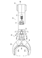
- the cutting device (hydraulic actuating device) according to the present embodiment is used for applications such as rescue, and can cut a round bar such as a reinforcing bar by a cutting portion.
- 1 to 12 are views showing a cutting device according to the present embodiment.
- 13 to 15 are views showing a pressure oil supply mechanism of a cutting device having another configuration according to the present embodiment.
- these oil passages and flow path adjustment valves are made easy to see such as oil passages and flow path adjustment valves for pressure oil and return oil.
- the description of the hatch to show the cross section in the surrounding part such as is omitted.
- the cutting device 10 includes a motor 20 such as an electric motor, a battery 22 composed of a secondary battery such as a lithium ion battery or a nickel hydrogen battery, and a round bar such as a reinforcing bar.
- a cutting portion 50 for cutting and an operating portion 21 for operating the cutting portion 50 are provided. More specifically, the cutting portion 50 has a pair of cutting members 64 and 66, and these cutting members 64 and 66 are rotatable about the shaft 68, respectively. Then, by rotating the cutting members 64 and 66 around the shaft 68 in a direction in which they approach each other, a round bar such as a reinforcing bar between the pair of cutting members 64 and 66 is cut.
- an operation handle 70 is attached to the operating portion 21, and the operator can adjust the rotation directions of the cutting members 64 and 66 centered on the shaft 68 by operating the operation handle 70. It has become.
- the operation handle 70 has a cylindrical shape, and when the operator holds the operation handle 70 by hand and rotates it in the forward direction or the reverse direction from the initial position, the cutting members 64 and 66 are shafts. It will rotate around 68 in the direction of approaching each other or in the direction of separating from each other. Further, in the present embodiment, when the operator releases the operation handle 70, the operation handle 70 returns to the initial position. When the operation handle 70 returns to the initial position, the cutting members 64 and 66 are stopped, respectively. The details of such an operation will be described later.
- a rotating shaft 24 is attached to the motor 20, and the rotating shaft 24 attached to the motor 20 can be rotated by supplying electric power from the battery 22 to the motor 20.
- An eccentric member 25 is attached to the tip of the rotating shaft 24.
- the eccentric member 25 is eccentric with respect to the axis of the rotating shaft 24, and a bearing such as a needle roller bearing is attached to the outer peripheral surface of the eccentric member 25.
- the operating portion 21 sends pressure oil from the piston 26 provided around the eccentric member 25, the oil chamber 28, and the oil chamber 28 to the cutting portion 50, and returns the pressure oil from the cutting portion 50 to the oil chamber 28.
- It has a pressure oil supply mechanism 30.
- the piston 26 moves up and down as the eccentric member 25 rotates. Further, the piston 26 is constantly pressed toward the outer peripheral surface of the bearing by a spring (not shown). Therefore, when the rotating shaft 24 is rotated by the motor 20, the eccentric member 25 and the bearing move eccentrically with respect to the axis of the rotating shaft 24, so that the piston 26 moves up and down, and the pressure oil supply mechanism 30 from the oil chamber 28.
- the pressure oil is sent toward the cut portion 50, and the pressure oil is supplied from the pressure oil supply mechanism 30 to the cutting portion 50 to operate the cutting portion 50.
- the configuration of the cutting portion 50 will be described with reference to FIGS. 1 and 2.
- the cutting portion 50 has a pair of cutting members 64 and 66 that are rotatable about a shaft 68, a base member 59, and a piston member 52 to which the base member 59 is attached to the tip. ..
- a blade portion 64b for cutting a round bar is provided at a position of the cutting member 64 facing the cutting member 66.
- a blade portion 66b for cutting a round bar is also provided at a position of the cutting member 66 facing the cutting member 64.
- the cutting member 64 and the base member 59 are connected by a connecting member 60.
- the cutting member 64 is connected to the connecting member 60 so as to be rotatable with respect to the connecting member 60 about a shaft 64a provided at the base end portion thereof.
- the connecting member 60 is connected to the base member 59 so as to be rotatable with respect to the base member 59 about a shaft 60a provided at the base end portion thereof.
- the cutting member 66 and the base member 59 are connected by a connecting member 62. More specifically, the cutting member 66 is connected to the connecting member 62 so as to be rotatable with respect to the connecting member 62 about a shaft 66a provided at the base end portion thereof. Further, the connecting member 62 is connected to the base member 59 so as to be rotatable with respect to the base member 59 about a shaft 62a provided at the base end portion thereof.
- the operating portion 21 that operates the cutting portion 50 is a pressure for sending pressure oil from the oil chamber 28 to the cutting portion 50 and returning the pressure oil from the cutting portion 50 to the oil chamber 28. It has an oil supply mechanism 30. Further, the operating portion 21 is provided with an operation handle 70 so that the operator can adjust the flow path of the pressure oil and the return oil by the pressure oil supply mechanism 30 by operating the operation handle 70. It has become. As a result, the operator can adjust the rotation directions of the cutting members 64 and 66 around the shaft 68 by operating the operation handle 70. Further, in the present embodiment, when the operator releases the operation handle 70, the operation handle 70 returns to the initial position, and in this case, the cutting members 64 and 66 are stopped, respectively. Details of the configurations of the two flow path adjusting valves 80 provided in the pressure oil supply mechanism 30, the operation handle 70, and the pressure oil supply mechanism 30 will be described below.
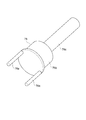
- the configuration of the operation handle 70 will be described with reference to FIGS. 3 to 6.
- the operator can rotate the operation handle 70 in both directions from the initial position.
- Such an operation handle 70 is supported by a handle support portion 72 attached to the actuating portion 21. Further, the operation handle 70 is rotatable with respect to the handle support portion 72.
- the rotation angle of the operation handle 70 from the initial position is limited to a size within a predetermined range. Further, after the operation handle 70 is rotated from the initial position, the operation handle 70 returns to the initial position when the operator releases the operation handle 70.
- the operation handle 70 is formed with two arcuate grooves 70a.
- each stopper pin 73 is attached to the handle support portion 72, respectively, and each stopper pin 73 fits into each groove 70a.
- a spring 74 is provided inside each groove 70a. One end of each spring 74 is in contact with the stopper pin 73, and the other end of each spring 74 is in contact with the end of the groove 70a.
- each groove 70a rotates with each stopper pin 73 fitted in each groove 70a.
- one of the two springs 74, the spring 74 is compressed between the end of the groove 70a and the stopper pin 73. Therefore, when the operator releases the operation handle 70, the operation handle 70 is rotated by the force that the compressed spring 74 tries to return to the original state, and returns to the original initial position.
- an initial position detection sensor 75 for detecting whether or not the operation handle 70 is in the initial position.
- the initial position detection sensor 75 has a protruding portion 75a that can move forward and backward toward the operation handle 70. Further, a recess 70b is formed on the outer peripheral surface of the operation handle 70. Then, as shown in FIG. 5, when the operation handle 70 is in the initial position, the protrusion 75a of the initial position detection sensor 75 enters the recess 70b of the operation handle 70. On the other hand, when the operator grasps the operation handle 70 by hand and rotates it from the initial position, the protrusion 75a comes out of the recess 70b. In this case, the protrusion 75a is pushed down in FIG. 5 by coming into contact with the outer peripheral surface of the operation handle 70. As a result, the initial position detection sensor 75 detects that the position of the operation handle 70 is no longer the initial position.
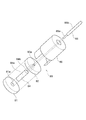
- a phase adjusting member 76 is attached to the operation handle 70.
- the axis of the operation handle 70 is the same as the axis of the phase adjusting member 76. Therefore, when the operator holds the operation handle 70 by hand and rotates it from the initial position, the phase adjusting member 76 also rotates synchronously.
- the phase adjusting member 76 includes a cylindrical main body portion 76b arranged inside the handle support portion 72 and two rod-shaped protruding portions 76a attached to one end surface of the main body portion 76b. And a base portion 76c attached to the other end face of the main body portion 76b.
- the base portion 76c is provided inside the operation handle 70, and when the operation handle 70 rotates, the base portion 76c also rotates integrally.
- each reciprocating member 78 moves in the vertical direction in FIGS. 7 to 9. Specifically, when the operation handle 70 is located at the initial position, each reciprocating member 78 is located at the neutral position as shown in FIG. In this case, the heights of the reciprocating members 78 in the vertical direction of FIG. 8 are the same.
- the phase adjusting member 76 rotates in the counterclockwise direction in FIGS. 7 to 9.
- the protrusion portion 76a on the left side of the two protrusions 76a descends and the protrusion portion 76a on the right side rises.
- the reciprocating member 78 on the left side in FIG. 9 descends from the neutral position, and the reciprocating member 78 on the right side rises from the neutral position.
- the position of each of the reciprocating members 78 is defined as the reverse position.
- the cutting portion 50 has a main body portion 56 in which an internal space for storing pressure oil is formed. Further, a partition member 54 for dividing the internal space formed inside the main body 56 into two regions is provided inside the main body 56. Further, the end portion of the piston member 52 is connected to the partition member 54. Of the two regions partitioned by the partition member 54 in the internal space where the pressure oil is stored, the region on the right side of the partition member 54 in FIG. 2 is a forward oil chamber, and the partition member 54 in FIG. The area on the left side is the reverse oil chamber 58. Although the volume of the advancing oil chamber is 0 in FIG. 2, when the partition member 54 moves to the left side in FIG.
- the advancing oil chamber is formed between the main body portion 56 and the partition member 54. .. Then, when the pressure oil is sent from the pressure oil supply mechanism 30 to the forward oil chamber, the partition member 54 is pushed by the pressure oil and moves to the left side in FIG. 2, and the piston member 52 also moves to the left side in FIG. On the other hand, when the pressure oil is sent from the pressure oil supply mechanism 30 to the reverse oil chamber 58, the partition member 54 moves to the right side in FIG. 2 by being pushed by the pressure oil, and the piston member 52 also moves to the right side in FIG. .. Further, an accommodation space for accommodating the rod-shaped member 51 is formed inside the piston member 52.
- a pressure oil flow path 51a is formed inside the rod-shaped member 51, and when pressure oil is sent from the pressure oil supply mechanism 30 described later to the flow path 51a of the rod-shaped member 51, this pressure oil becomes reverse oil. It will be sent to room 58.
- the pressure oil supply mechanism 30 sends pressure oil from the oil chamber 28 to the cutting portion 50 and returns the oil from the cutting portion 50 to the oil chamber 28.
- a plurality of oil passages 32, 33, 34, 36, 37, 38, 40, 42, 45, 46, 47 are provided for this purpose.
- the pressure oil supply mechanism 30 has two flow path adjusting valves 80. These two flow path adjusting valves 80 adjust which flow path the pressure oil sent from the oil chamber 28 to the cutting portion 50 and the return oil returned from the cutting portion 50 to the oil chamber 28 pass through. ing.
- each of the two flow path adjusting valves 80 is operated by the operation handle 70. Specifically, each flow path adjusting valve 80 is operated by moving each reciprocating member 78 up and down.
- the first oil passage 32 communicates with the oil chamber 28, and the second oil passage 33 communicates with the first oil passage 32. Further, a first seal plate 81 (described later) of the flow path adjusting valve 80 on the left side is provided between the first oil passage 32 and the second oil passage 33. Further, the third oil passage 34 communicates with the second oil passage 33. Further, the third oil passage 34 communicates with the fourth oil passage 36, and the fourth oil passage 36 communicates with the fifth oil passage 38.
- the fifth oil passage 38 communicates with the forward oil chamber in the region on the right side of the partition member 54 of FIG. 2 in the internal space formed inside the main body 56.
- a sixth oil passage 37 is provided around the base portion 86 (described later) of the flow path adjusting valve 80 on the left side, and the sixth oil passage 37 is the second oil passage 37 of the flow path adjusting valve 80 on the left side. It communicates with the third oil passage 34 via a seal plate 82 (described later).
- a seventh oil passage 40 communicates with the flow path 51a of the rod-shaped member 51. Further, the seventh oil passage 40 communicates with the eighth oil passage 47, and the eighth oil passage 47 communicates with the ninth oil passage 46.
- a first seal plate 81 (described later) of the flow path adjusting valve 80 on the right side is provided between the first oil passage 32 and the ninth oil passage 46.
- a tenth oil passage 42 is provided around the base portion 86 (described later) of the flow path adjusting valve 80 on the right side, and the tenth oil passage 42 is the first of the flow path adjusting valve 80 on the right side. It communicates with the ninth oil passage 46 via a two-seal plate 82 (described later).
- a drain pipe 44 for returning the pressure oil to the oil chamber 28 is provided, and the drain pipe 44 communicates with the eleventh oil passage 45.
- the eleventh oil passage 45 communicates with the sixth oil passage 37 and the tenth oil passage 42, respectively.
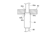
- each flow path adjusting valve 80 is a valve provided between the first seal plate 81, the second seal plate 82, the first seal plate 81, and the second seal plate 82. It has a seat 83, a seal pin 84 provided inside the valve seat 83, an actuating pin 85 attached to the seal pin 84, and a base portion 86 through which the actuating pin 85 penetrates.
- the valve seat 83 is omitted in order to make the seal pin 84 easier to see. More specifically, as shown in FIGS.
- the seal pin 84 has a cylindrical portion 84a and one end of the cylindrical portion 84a (specifically, an end on the second seal plate 82 side). It has a spherical end surface 84b provided in the above. Further, the actuating pin 85 has a first cylindrical portion 85a and a second cylindrical portion 85b having a diameter larger than that of the first cylindrical portion 85a, and the tip of the first cylindrical portion 85a is a seal pin 84. It is attached to the ball end surface 84b of.
- the first seal plate 81 is formed with a through hole 81a having a uniform diameter.
- the diameter of the through hole 81a is substantially the same as the diameter of the cylindrical portion 84a of the seal pin 84. Therefore, when the cylindrical portion 84a of the seal pin 84 enters the through hole 81a of the first seal plate 81, the through hole 81a of the first seal plate 81 is sealed by the seal pin 84.
- a through hole including a first through hole 82a and a second through hole 82b is formed in the second seal plate 82.
- the diameter of the second through hole 82b is larger than the diameter of the first through hole 82a.
- the diameter of the first through hole 82a is smaller than the diameter of the cylindrical portion 84a of the seal pin 84.
- the diameter of the second through hole 82b is larger than the diameter of the cylindrical portion 84a of the seal pin 84.
- the diameter of the first through hole 82a is larger than the diameter of the first cylindrical portion 85a of the operating pin 85.
- an inclined surface 82c is formed between the first through hole 82a and the second through hole 82b.
- a first seal plate 81 is attached to one end surface of the valve seat 83.
- a second seal plate 82 is attached to the other end face of the valve seat 83.
- a through hole is formed in the valve seat 83, and the seal pin 84 moves up and down inside the through hole.
- the diameter of the through hole of the valve seat 83 is larger than the diameter of the cylindrical portion 84a of the seal pin 84. Therefore, the pressure oil can pass through the gap between the outer peripheral surface of the through hole of the valve seat 83 and the outer peripheral surface of the cylindrical portion 84a of the seal pin 84.
- the base portion 86 is attached to the surface of the second seal plate 82 opposite to the surface to which the valve seat 83 is attached.
- a through hole is formed in the base portion 86, and the operating pin 85 moves up and down inside the through hole.
- the diameter of the through hole of the base portion 86 is substantially the same as the diameter of the second cylindrical portion 85b of the operating pin 85. Therefore, the through hole of the base portion 86 is sealed by the operating pin 85.
- one end of the connecting portion 89 is connected to the lower end surface of the cylindrical portion 84a of the seal pin 84 in each flow path adjusting valve 80, and the other end of the connecting portion 89 is sealed.
- a plate 87 is attached.
- a spring 88 is arranged below the seal plate 87 in a compressed state. As a result, the seal plate 87 is pushed upward as shown in FIGS. 7 to 9 by the force that the compressed spring 88 tries to return to the original state.
- each reciprocating member 78 when each reciprocating member 78 is located in the neutral position, the upper end of the second cylindrical portion 85b of each operating pin 85 is in contact with the pushing portion 78b of each reciprocating member 78. .. Specifically, the seal plate 87 is pushed upward as shown in FIGS. 7 to 9 by the force of the compressed spring 88 trying to return to the original state, so that the seal plate 87 is moved to the seal plate 87 via the connection portion 89. The connected seal pin 84 and actuating pin 85 are also pushed upward as shown in FIGS. 7 to 9.
- the through hole of the second seal plate 82 is sealed by the seal pin 84 in the flow path adjusting valve 80 on the left side.
- the first seal plate 81 is not sealed by the seal pin 84 in the flow path adjusting valve 80 on the left side.
- the reciprocating member 78 on the right side is lowered, so that the pushing portion 78b of the reciprocating member 78 pushes the second cylindrical portion 85b of the operating pin 85 on the right side downward. To do.
- the cylindrical portion 84a of the seal pin 84 enters the through hole 81a of the first seal plate 81, so that the through hole 81a of the first seal plate 81 is sealed by the seal pin 84. Will be done.
- the second seal plate 82 is not sealed by the seal pin 84 in the flow path adjusting valve 80 on the right side.
- the operation of the cutting device 10 having such a configuration will be described below.
- the motor 20 is driven by supplying electric power from the battery 22 to the motor 20.
- the eccentric member 25 and the bearing move eccentrically with respect to the axis of the rotating shaft 24, so that the piston 26 moves up and down, and the oil chamber 28 moves to the pressure oil supply mechanism 30. Pressure oil is sent toward.
- the through hole 81a of the first seal plate 81 is sealed by the seal pin 84.
- the second seal plate 82 is not sealed by the seal pin 84 in the flow path adjusting valve 80 on the right side.
- the pressure oil sent from the oil chamber 28 to the pressure oil supply mechanism 30 is the first seal plate of the flow path adjusting valve 80 on the left side from the first oil passage 32. It is sent to the second oil passage 33 through the through hole 81a of 81. Then, the pressure oil is sent from the second oil passage 33 to the fourth oil passage 36 via the third oil passage 34. At this time, since the through hole of the second seal plate 82 is sealed by the seal pin 84 in the flow path adjusting valve 80 on the left side, the pressure oil is sent from the third oil passage 34 to the sixth oil passage 37. There is no. Then, the pressure oil is sent from the fourth oil passage 36 to the fifth oil passage 38.
- the oil is sent back to the drain pipe 44 from the tenth oil passage 42 through the eleventh oil passage 45. In this way, the oil is returned from the drain pipe 44 to the oil chamber 28. Since the through hole 81a of the first seal plate 81 is sealed by the seal pin 84 in the flow path adjusting valve 80 on the right side, the return oil may be sent from the ninth oil passage 46 to the first oil passage 32. Absent.
- each reciprocating member 78 returns to the position shown in FIG.
- the seal plate 87 is pushed upward as shown in FIG. 8 by a force that causes the compressed spring 88 to return to the original state, so that the seal pin 84 is connected to the seal plate 87 via the connection portion 89.
- the actuating pin 85 is also pushed upward as shown in FIG.
- the pressure oil sent from the oil chamber 28 to the pressure oil supply mechanism 30 is the first seal plate of the flow path adjusting valve 80 on the left side from the first oil passage 32. It is sent to the second oil passage 33 through the through hole 81a of 81. Then, the pressure oil is sent from the second oil passage 33 to the sixth oil passage 37 via the third oil passage 34. At this time, the pressure oil is sent from the third oil passage 34 to the sixth oil passage 37 by passing through the gap between the outer peripheral surface of the through hole of the valve seat 83 and the opposite peripheral surface of the seal pin 84. Will be able to. Then, the pressure oil is sent from the sixth oil passage 37 to the drain pipe 44 through the eleventh oil passage 45.
- the pressure oil is returned from the drain pipe 44 to the oil chamber 28.
- the pressure oil sent from the oil chamber 28 to the pressure oil supply mechanism 30 penetrates through the through hole 81a of the first seal plate 81 and the second seal plate 82 of the flow path adjusting valve 80 on the right side from the first oil passage 32. It is sent to the tenth oil passage 42 through the hole. Then, the pressure oil is sent from the tenth oil passage 42 to the drain pipe 44 through the eleventh oil passage 45. In this way, the pressure oil is returned from the drain pipe 44 to the oil chamber 28. In this way, when each reciprocating member 78 is located in the neutral position, the pressure oil sent from the oil chamber 28 to the pressure oil supply mechanism 30 is returned to the oil chamber 28 by the drain pipe 44. Therefore, the pressure oil is not sent to both the forward oil chamber and the reverse oil chamber 58, so that the piston member 52 does not move. As a result, the operation of the cutting portion 50 is stopped.
- the cutting portion 50 cuts a round bar such as a reinforcing bar and then returns the cutting portion 50 to the open state of the cutting members 64 and 66 as shown in FIG. 1, the operator presses the operation handle 70. Hold it with your hand and rotate the operation handle 70 to the left.
- the phase adjusting member 76 rotates in the counterclockwise direction in FIGS. 7 to 9, and as shown in FIG. 9, the right protrusion 76a of the two protrusions 76a rises and the left protrusion 76a rises. Part 76a descends.
- each reciprocating member 78 moves to the reverse position as shown in FIG.
- the through hole 81a of the first seal plate 81 is sealed by the seal pin 84 in the flow path adjusting valve 80 on the left side.
- the second seal plate 82 is not sealed by the seal pin 84 in the flow path adjusting valve 80 on the left side.
- the through hole of the second seal plate 82 is sealed by the seal pin 84.
- the first seal plate 81 is not sealed by the seal pin 84 in the flow path adjusting valve 80 on the right side.
- the tool (specifically, the cutting portion 50) and the pressure oil are sent from the oil chamber 28 to the tool and from the tool.
- An operating unit 21 having a pressure oil supply mechanism 30 for returning the return oil to the oil chamber 28, an operation handle 70 for adjusting the pressure oil and return oil oil passages of the pressure oil supply mechanism 30, and an external operation handle 70.
- An urging means (specifically, a stopper pin 73 and a spring 74) is provided to urge the operation handle 70 toward the initial position when no force is applied from the oil.
- the operation handle 70 can be moved from the initial position, and when the operation handle 70 moves from the initial position, the tool is operated by the operating portion 21, and the operation handle 70 is returned to the initial position by the urging means. Then, the operation of the tool by the operating unit 21 is stopped.
- a cutting device 10 for example, when an operator holds the operation handle 70 with one hand and operates it, the operation of the tool is stopped only by releasing the hand from the operation handle 70, so that the safety is improved. Can be made to.
- the cutting portion 50 as a tool has a tool member (specifically, a pair of cutting members 64, 66) and an oil chamber that advances the internal space. It also has a partition member 54 for partitioning the reverse oil chamber 58, and a piston member 52 attached to the partition member 54 for moving the tool member. Then, when the operation handle 70 moves from the initial position, the partition member 54 and the piston member 52 move by sending pressure oil from the oil chamber 28 to the forward oil chamber or the reverse oil chamber 58 of the tool by the operating portion 21. At this time, the return oil is returned from the forward oil chamber or the reverse oil chamber 58 to the oil chamber 28.
- a tool member specifically, a pair of cutting members 64, 66
- an oil chamber that advances the internal space. It also has a partition member 54 for partitioning the reverse oil chamber 58, and a piston member 52 attached to the partition member 54 for moving the tool member. Then, when the operation handle 70 moves from the initial position, the partition member 54 and the piston member 52 move by sending pressure oil from the oil chamber 28 to
- the operation handle 70 is rotated from the initial position in the first rotation direction and the second rotation direction opposite to the first rotation direction. Can be done. Then, when the operation handle 70 rotates in the first rotation direction from the initial position, the tool member of the tool (specifically, the cutting members 64 and 66 of the cutting portion 50) is moved in the first direction (specifically) by the operating portion 21. Moves in the direction of the arrow in FIG. Further, when the operation handle 70 rotates in the second rotation direction from the initial position, the tool member of the tool moves in the second direction opposite to the first direction by the operating portion 21.
- the cutting device 10 is provided with a pair of reciprocating members 78, and when the operation handle 70 is moved, the reciprocating members 78 are moved from the neutral position (see FIG. 8) in opposite directions to each other.
- the pressure oil supply mechanism 30 has a pair of flow path adjusting valves 80 corresponding to the pair of reciprocating members 78, and each flow path adjusting valve 80 allows the oil chamber 28 to be used as a tool (specifically, a cutting portion). The oil passage for the pressure oil up to 50) and the oil passage for the return oil from the tool to the oil chamber 28 are adjusted. Further, as shown in FIG.
- the partition member 54 and the piston member 52 are in the opposite directions to the first direction because the oil passage for the pressure oil to the oil chamber 58 and the oil passage for the return oil from the oil chamber to the advancing oil chamber of the tool are communicated with each other. Move in the second direction (ie, to the right in FIGS. 1 and 2).
- each reciprocating member 78 that is moved in opposite directions from the neutral position as shown in FIG. 8 when the operation handle 70 is rotated is used and corresponds to each reciprocating member 78.
- the pair of flow path adjusting valves 80 By using the pair of flow path adjusting valves 80, the forward movement and the backward movement of the piston member 52 can be smoothly performed. More specifically, in the cutting device 10 of the present embodiment, when the operation handle 70 rotates from the initial position, the tool is operated by the operating unit 21, and when the operating handle 70 is returned to the initial position by the urging means, the operating unit is operated.
- the structure is such that the operation of the tool by 21 is stopped, but if only one flow path adjusting valve 80 is provided, the flow path is adjusted even if the operation handle 70 is returned to the initial position.
- the valve 80 may not smoothly return to the neutral position, and thus the tool operation may not stop smoothly.
- the pair of flow path adjusting valves 80 when used, the height levels of the reciprocating members 78 are the same, so that when the pair of flow path adjusting valves 80 are at the same height level, the pair of flow paths In the adjusting valve 80, the first seal plate 81 and the second seal plate 82 are not sealed by the seal pins 84, respectively. Therefore, the pressure oil sent from the oil chamber 28 to the pressure oil supply mechanism 30 is returned to the oil chamber 28 by the drain pipe 44 as it is, so that the pressure oil supply mechanism 30 moves forward and backward in the cutting portion 50. Pressure oil is no longer sent to the oil chamber 58, and the operation of the cutting portion 50 can be smoothly stopped.
- each flow path adjusting valve 80 has a first seal plate 81 provided with a through hole 81a and a second seal provided with a through hole (specifically, a first through hole 82a and a second through hole 82b). It has a seal pin 84 for sealing the through hole 81a of the plate 82 and the first seal plate 81 or the through hole of the second seal plate 82, and the seal pin 84 is moved by the reciprocating member 78. Further, when the reciprocating member 78 is located in the neutral position, the through hole 81a of the first seal plate 81 and the through hole of the second seal plate 82 are not sealed by the seal pin 84.
- the through hole 81a of the first seal plate 81 is sealed by the seal pin 84 in one flow path adjusting valve 80, and the seal pin 84 seals the second through hole 81a in the other flow path adjusting valve 80.
- the through hole of the seal plate 82 is sealed.
- each flow path adjusting valve 80 the seal plates 81 and 82 sealed by the seal pin 84 in each flow path adjusting valve 80 are different depending on whether the operation handle 70 is rotated in the first rotation direction from the initial position and in the second rotation direction. It has become like.
- the seal pin 84 has a cylindrical portion 84a and a spherical end surface 84b provided at one end of the cylindrical portion 84a.
- the diameter of the through hole 81a of the first seal plate 81 is the same as the diameter of the cylindrical portion 84a of the seal pin 84, and the seal pin 84 is inserted into the through hole 81a of the first seal plate 81.
- the through hole 81a of the first seal plate 81 is sealed.
- the second seal plate 82 has a first through hole 82a having a diameter smaller than the diameter of the cylindrical portion 84a of the seal pin 84 and a second through hole 82b having a diameter larger than the diameter of the cylindrical portion 84a of the seal pin 84.
- a seal pin 84 having a cylindrical portion 84a and a spherical end surface 84b provided at one end of the cylindrical portion 84a two-stage cylindrical portions 84q and 84r as described later are used. Since the cylindrical portion 84a has one stage as compared with the case of manufacturing the sealing pin 84p having the seal pin 84p, the processing accuracy of the outer diameter portion of the cylindrical portion 84a can be improved. Therefore, the clearance between the through hole 81a of the first seal plate 81 and the cylindrical portion 84a of the seal pin 84 can be set accurately, and thus the outer peripheral surface of the through hole 81a of the first seal plate 81 and the seal pin 84.
- an inclined surface 82c is formed between the first through hole 82a and the second through hole 82b, and the second through hole 82b of the second seal plate 82 has a cylindrical shape of the seal pin 84.
- the portion 84a enters the spherical end surface 84b comes into contact with the inclined surface 82c, so that the through hole of the second seal plate 82 is sealed.
- the flow path adjusting valve 80a shown in FIGS. 13 to 15 is used instead of using the pressure oil supply mechanism 30 having the flow path adjusting valve 80 shown in FIGS. 7 to 12, the flow path adjusting valve 80a shown in FIGS. 13 to 15 is used.
- the pressure oil supply mechanism 30a having the pressure oil supply mechanism 30a may be used.
- the same components as those of the flow path adjusting valve 80 shown in FIGS. 7 to 12 are designated by the same reference numerals, and the description thereof will be omitted.
- the first cylindrical shape is used instead of the seal pin 84 provided with the spherical end surface 84b at one end of the cylindrical portion 84a as shown in FIGS. 10 to 12.
- a seal pin 84p having a second cylindrical portion 84r having a diameter smaller than the diameter of the portion 84q and the first cylindrical portion 84q has been used. That is, the seal pin 84p is composed of a two-stage cylindrical portion. Further, instead of the first seal plate 81 and the second seal plate 82, the first seal plate 81p and the second seal plate 82p are used, respectively.
- the first seal plate 81p is formed with through holes having a uniform diameter.
- the diameter of the through hole is substantially the same as the diameter of the first cylindrical portion 84q of the seal pin 84p. Therefore, when the first cylindrical portion 84q of the seal pin 84p enters the through hole of the first seal plate 81p, the through hole of the first seal plate 81p is sealed by the seal pin 84p.
- the second seal plate 82p is also formed with a through hole having a uniform diameter. The diameter of the through hole is substantially the same as the diameter of the second cylindrical portion 84r of the seal pin 84p.
- the valve seat 83p provided between the first seal plate 81p and the second seal plate 82p has the same configuration as the valve seat 83 of the flow path adjusting valve 80 shown in FIGS. 7 to 12.
- the diameter of the through hole of the valve seat 83p is larger than the diameter of the first cylindrical portion 84q of the seal pin 84p.
- each operating pin 85 is attached to the pushing portion 78b of each reciprocating member 78.
- the upper end of the second cylindrical portion 85b of the above is in contact with each other.
- the seal plate 87 is pushed upward as shown in FIGS. 13 to 15 by the force that the compressed spring 88 tries to return to the original state, so that the seal plate 87 is moved to the seal plate 87 via the connection portion 89.
- the connected seal pin 84p and actuating pin 85 are also pushed upward as shown in FIGS. 13 to 15.
- the first seal plate 81p is not sealed by the seal pin 84p in the flow path adjusting valve 80a on the left side. Further, when each reciprocating member 78 moves to the forward position, the reciprocating member 78 on the right side is lowered, so that the pushing portion 78b of the reciprocating member 78 pushes the second cylindrical portion 85b of the operating pin 85 on the right side downward. To do. As a result, in the flow path adjusting valve 80a on the right side, the first cylindrical portion 84q of the seal pin 84p enters the through hole of the first seal plate 81p, so that the through hole of the first seal plate 81p is sealed by the seal pin 84p. Will be done. In this state, the second seal plate 82p is not sealed by the seal pin 84p in the flow path adjusting valve 80a on the right side.
- the flow path adjusting valve 80a is provided.
- the 80a may not smoothly return to the neutral position, and therefore the operation of the cutting portion 50 may not stop smoothly.
- the pressure oil supply mechanism 30a having a pair of flow path adjusting valves 80a is used, the height levels of the reciprocating members 78 are the same, so that the pair of flow path adjusting valves 80a have the same height.
- the first seal plate 81p and the second seal plate 82p are not sealed by the seal pins 84p in the pair of flow path adjusting valves 80a, respectively. Therefore, the pressure oil sent from the oil chamber 28 to the pressure oil supply mechanism 30a is returned to the oil chamber 28 by the drain pipe 44 as it is. Pressure oil is no longer sent to the oil chamber 58, and the operation of the cutting portion 50 can be smoothly stopped.
- the first cylindrical portion 84q of the seal pin 84p is inserted into the through hole of the first seal plate 81p. Is inserted to seal the through hole of the first seal plate 81p, and the second cylindrical portion 84r of the seal pin 84p is inserted into the through hole of the second seal plate 82p to form the second seal plate 82p. The through hole is sealed. In this case, pressure oil may leak between the outer peripheral surface of the through hole of the first seal plate 81p and the outer peripheral surface of the seal pin 84p, or the outer peripheral surface of the through hole of the second seal plate 82p and the seal pin 84p.
- the pressure oil supply mechanism shown in FIG. 16 has one elongated spool valve 160 having a substantially cylindrical shape, and a hole 170 having a substantially circular cross section for accommodating the spool valve 160.
- the size of the diameter of the spool valve 160 and the size of the diameter of the hole 170 are the same.
- pressure oil does not pass between the outer peripheral surface of the spool valve 160 and the outer peripheral surface of the hole 170.
- a spring 164 is provided at one end of the spool valve 160, and a spring 166 is also provided at the other end of the spool valve 160.
- Such a spool valve 160 is movable in the vertical direction in FIG.
- the spool valve 160 moves upward or downward from the neutral position in FIG. Further, when the spool valve 160 moves upward or downward from the neutral position as shown in FIG. 16 and no external force is applied to the spool valve 160, the compressed spring 164 or spring 166 is in the original state. The spool valve 160 returns to its original neutral position due to the force of returning to.
- a first oil passage 132 is provided so as to face the hole 170, and the first oil passage 132 communicates with the oil chamber 28. Further, one end of the second oil passage 134 is provided so as to face the hole 170. When the spool valve 160 is in the neutral position, the second oil passage 134 faces the outer peripheral surface of the spool valve 160. Further, the second oil passage 134 communicates with the third oil passage 136, and the third oil passage 136 communicates with the advancing oil chamber of the cutting portion 50. Further, one end of the fourth oil passage 138 is provided so as to face the hole 170. When the spool valve 160 is in the neutral position, the fourth oil passage 138 faces the outer peripheral surface of the spool valve 160.
- the fourth oil passage 138 communicates with the fifth oil passage 140
- the fifth oil passage 140 communicates with the reverse oil chamber 58 of the cutting portion 50.
- two drain pipes 142 and 144 are formed so as to face the hole 170, and the pressure oil is returned to the oil chamber 28 by each of the drain pipes 142 and 144.
- a groove 162 is formed on a part of the outer peripheral surface of the spool valve 160. Further, a groove 172 is also formed on the outer peripheral surface of the hole 170. Pressure oil can pass through such grooves 162 and 172 between the outer peripheral surface of the spool valve 160 and the outer peripheral surface of the hole 170.
- the end of the second oil passage 134 and the end of the fourth oil passage 138 face the outer peripheral surface of the spool valve 160, respectively. Therefore, the first oil passage 132 and the second oil passage 134 do not communicate with each other. Further, the first oil passage 132 and the fourth oil passage 138 do not communicate with each other. As a result, the pressure oil is not sent from the oil chamber 28 to the forward oil chamber and the reverse oil chamber 58 of the cutting portion 50, and the partition member 54 does not move, so that the cutting portion 50 does not operate. Further, when the spool valve 160 moves upward from the neutral position in FIG.
- the end of the second oil passage 134 and the end of the fourth oil passage 138 are spooled, respectively. It faces the groove 162 formed on the outer peripheral surface of the valve 160.
- the first oil passage 132 and the second oil passage 134 communicate with each other, so that the oil chamber 28 to the first oil passage 132, the second oil passage 134, and the third oil passage 136 Pressure oil is sent to the advancing oil chamber of the cutting portion 50 via the above.
- the partition member 54 and the piston member 52 are integrally moved to the left in FIGS. 1 and 2, so that the cutting members 64 and 66 approach each other about the shaft 68 in the cutting portion 50. Rotate in the direction.
- return oil is sent from the reverse oil chamber 58 of the cutting portion 50 to the fifth oil passage 140, and this return oil is drained from the fifth oil passage 140 to the fourth oil passage 138. It is returned to the oil chamber 28 by 144.
- the end of the second oil passage 134 and the end of the fourth oil passage 138 are spooled, respectively. It faces the groove 162 formed on the outer peripheral surface of the valve 160.
- the first oil passage 132 and the fourth oil passage 138 communicate with each other, so that the oil chamber 28 to the first oil passage 132, the fourth oil passage 138, and the fifth oil passage 140 Pressure oil is sent to the reverse oil chamber 58 of the cutting portion 50 via the above.
- the partition member 54 and the piston member 52 move integrally in the right direction in FIGS.
- the spool valve 160 may not return to the original neutral position due to the spring 164 or the spring 166 when the hand is released from the operation handle 70, so that the operation of the cutting portion 50 may not stop smoothly.
- the pair of flow path adjusting valves 80 or the pair of flow path adjusting valves 80a are used as described above, it is possible to suppress the occurrence of such a problem.
- the hydraulic actuator according to the present invention is not limited to the above-described embodiment, and various modifications can be made.
- the tool operated by the operating portion 21 is not limited to the cutting portion 50.
- a spreader or the like for prying open a gap of an object such as a door may be used.
Abstract
油圧作動装置(例えば、切断装置10)は、工具(例えば、切断部50)と、油室28から圧油を工具に送るとともに工具からの戻り油を油室28に戻す圧油供給機構30を有する作動部21と、圧油供給機構30の圧油および戻り油の油路を調整するための操作ハンドル70であって、初期位置から移動させることができるようになっている操作ハンドル70と、操作ハンドル70に外部から力が作用していないときに当該操作ハンドル70を初期位置に向かって付勢する付勢手段(例えば、ストッパーピン73およびスプリング74)とを備えている。操作ハンドル70が初期位置から移動すると作動部21により工具が作動され、付勢手段により操作ハンドル70が初期位置に戻されると作動部21による工具の動作が停止される。
Description
本発明は、油圧により工具が作動するような油圧作動装置に関する。
従来から、レスキューの用途に可搬型の油圧作動装置を利用することが行われており、その一例が例えば日本国特許出願の公開公報である特開2010-280011号公報(JP2010-280011A)等に記載されている。特開2010-280011号公報に開示される油圧作動装置は、バッテリー、このバッテリーから給電される電動モータおよびこの電動モータにより駆動される油圧ポンプを有する油圧発生ユニットと、油圧発生ユニットに着脱可能であり、当該油圧発生ユニットにより発生する圧油により駆動される先端工具を有するヘッドユニットとから構成されている。ヘッドユニットに設けられる先端工具として、カッター、スプレッダーなどの様々な種類のものが用意されており、ヘッドユニットを交換することにより多種多様な作業に対応することができる。
従来の油圧作動装置では、操作者が操作ハンドルを手で握ってこの操作ハンドルを初期位置から動作位置に移動させることによりヘッドユニットが動作するようになっている。また、操作者が手で握っている操作ハンドルを動作位置から初期位置に戻すとヘッドユニットの動作が停止するようになる。
しかしながら、近年では、レスキューの用途で用いられる可搬型の油圧作動装置の安全性を向上させるために、操作者が操作ハンドルを手で握ってこの操作ハンドルを初期位置から動作位置に移動させた後、操作者が操作ハンドルから手を離すだけでヘッドユニットの動作が停止するような油圧作動装置が求められている。
本発明は、このような点を考慮してなされたものであり、操作ハンドルを手で握ってこの操作ハンドルを初期位置から移動させて工具を動作させた後、操作者が操作ハンドルから手を離すだけで工具の動作が停止することにより安全性を向上させることができる油圧作動装置を提供することを目的とする。
本発明の油圧作動装置は、工具と、油室から圧油を前記工具に送るとともに前記工具からの戻り油を前記油室に戻す圧油供給機構を有する作動部と、前記圧油供給機構の圧油および戻り油の油路を調整するための操作ハンドルであって、初期位置から移動させることができるようになっている操作ハンドルと、前記操作ハンドルに外部から力が作用していないときに当該操作ハンドルを前記初期位置に向かって付勢する付勢手段と、を備え、前記操作ハンドルが前記初期位置から移動すると前記作動部により前記工具が作動され、前記付勢手段により前記操作ハンドルが前記初期位置に戻されると前記作動部による前記工具の動作が停止されることを特徴とする。
本発明の油圧作動装置においては、前記工具は、工具部材と、圧油が貯留される内部空間を前進油室および後進油室に区画する区画部材と、前記区画部材に取り付けられ、前記工具部材を移動させるピストン部材と、を有しており、前記操作ハンドルが前記初期位置から移動すると、前記作動部により前記油室から前記工具の前記前進油室または前記後進油室に圧油が送られることにより前記区画部材および前記ピストン部材が移動し、この際に前記後進油室または前記前進油室から戻り油が前記油室に戻されるようになっていてもよい。
また、前記操作ハンドルは前記初期位置から第1の回転方向および第1の回転方向とは逆方向の第2の回転方向に回転させることができるようになっており、前記操作ハンドルが前記初期位置から第1の回転方向に回転すると前記作動部により前記工具の前記工具部材が第1の方向に移動し、前記操作ハンドルが前記初期位置から第2の回転方向に回転すると前記作動部により前記工具の前記工具部材が第1の方向とは逆方向の第2の方向に移動するようになっていてもよい。
また、本発明の油圧作動装置は、一対の往復部材を更に備え、前記操作ハンドルが回転させられると各前記往復部材は中立位置から互いに反対方向に移動させられるようになっており、前記圧油供給機構は、一対の前記往復部材に対応する一対の流路調整バルブを有しており、各流路調整バルブにより前記油室から前記工具までの圧油の油路および前記工具から前記油室までの戻り油の油路が調整されるようになっており、前記操作ハンドルが前記初期位置から第1の回転方向に回転することにより各前記往復部材が中立位置から互いに反対方向に移動させられると、前記油室から前記工具の前記前進油室までの圧油の油路および前記工具の前記後進油室から前記油室までの戻り油の油路がそれぞれ連通することにより前記区画部材および前記ピストン部材が第1の方向に移動し、前記操作ハンドルが前記初期位置から第2の回転方向に回転することにより各前記往復部材が中立位置から互いに反対方向に移動させられると、前記油室から前記工具の前記後進油室までの圧油の油路および前記工具の前記前進油室から前記油室までの戻り油の油路がそれぞれ連通することにより前記区画部材および前記ピストン部材が第1の方向とは逆方向の第2の方向に移動するようになっていてもよい。
また、各前記流路調整バルブは、貫通穴が設けられた第1シールプレート、貫通穴が設けられた第2シールプレートおよび前記第1シールプレートの前記貫通穴または前記第2シールプレートの前記貫通穴をシールするためのシールピンを有しており、前記シールピンは前記往復部材により移動させられるようになっており、前記往復部材が中立位置に位置しているときには前記シールピンにより前記第1シールプレートの前記貫通穴および前記第2シールプレートの前記貫通穴はシールされず、前記往復部材が中立位置から移動すると、一方の前記流路調整バルブにおいて前記シールピンにより前記第1シールプレートの前記貫通穴がシールされるとともに他方の前記流路調整バルブにおいて前記シールピンにより前記第2シールプレートの前記貫通穴がシールされるようになっていてもよい。
また、前記操作ハンドルが前記初期位置から第1の回転方向に回転した場合と第2の回転方向に回転した場合とで各前記流路調整バルブにおいて前記シールピンによりシールされるシールプレートが異なるようになっていてもよい。
また、前記シールピンは、円柱形状部分と、前記円柱形状部分の一方の端部に設けられた球端面とを有しており、前記第1シールプレートの前記貫通穴の直径は前記シールピンの前記円柱形状部分の直径と同一の大きさとなっており、前記第1シールプレートの前記貫通穴に前記シールピンが挿入されることにより前記第1シールプレートの前記貫通穴がシールされるようになっており、前記第2シールプレートには、前記シールピンの前記円柱形状部分の直径よりも小さな直径の第1貫通穴および前記シールピンの前記円柱形状部分の直径よりも大きな直径の第2貫通穴が形成されており、前記第2シールプレートの前記第2貫通穴に前記シールピンの前記円柱形状部分が入ったときに前記球端面が前記第1貫通穴と前記第2貫通穴の間の箇所に接触することにより前記第2シールプレートの前記第1貫通穴および前記第2貫通穴がシールされるようになっていてもよい。
また、前記第2シールプレートにおいて前記第1貫通穴と前記第2貫通穴との間には傾斜面が形成されており、前記第2シールプレートの前記第2貫通穴に前記シールピンの前記円柱形状部分が入ったときに前記球端面が前記傾斜面に接触することにより前記第2シールプレートの前記第1貫通穴および前記第2貫通穴がシールされるようになっていてもよい。
以下、図面を参照して本発明の実施の形態について説明する。本実施の形態による切断装置(油圧作動装置)は、レスキュー等の用途に使用されるものであり、切断部により鉄筋等の丸棒を切断することができるものである。図1乃至図12は、本実施の形態による切断装置を示す図である。また、図13乃至図15は、本実施の形態による他の構成の切断装置の圧油供給機構を示す図である。なお、図2乃至図4、図7乃至図9および図13乃至図15において、圧油や戻り油の油路や流路調整バルブ等を見やすくするために、これらの油路や流路調整バルブ等の周囲の箇所における断面を示すためのハッチの描写を省略している。
図1等に示すように、本実施の形態による切断装置10は、電動モータ等のモータ20と、リチウムイオン電池またはニッケル水素電池等の二次電池からなるバッテリー22と、鉄筋等の丸棒を切断するための切断部50と、切断部50を作動させるための作動部21とを備えている。より詳細には、切断部50は一対の切断部材64、66を有しており、これらの切断部材64、66はそれぞれ軸68を中心として回転可能となっている。そして、軸68を中心として各切断部材64、66を互いに接近させる方向に回転させることによって一対の切断部材64、66の間にある鉄筋等の丸棒が切断されるようになっている。また、作動部21には操作ハンドル70が取り付けられており、作業者はこの操作ハンドル70を操作することによって軸68を中心とした各切断部材64、66の回転方向を調整することができるようになっている。本実施の形態では操作ハンドル70は円柱形状のものとなっており、作業者が操作ハンドル70を手で握って初期位置から正方向または逆方向に回転させることにより各切断部材64、66は軸68を中心として互いに接近する方向または互いに離間する方向に回転するようになる。また、本実施の形態では作業者が操作ハンドル70から手を離すとこの操作ハンドル70は初期位置に戻るようになっている。操作ハンドル70が初期位置に戻ると、各切断部材64、66はそれぞれ停止する。このような動作の詳細については後述する。
図2に示すように、モータ20には回転軸24が取り付けられており、バッテリー22からモータ20に電力が供給されることにより、モータ20に取り付けられた回転軸24が回転させられるようになっている。また、回転軸24の先端には偏心部材25が取り付けられている。偏心部材25は、回転軸24の軸線に対して偏心しており、当該偏心部材25の外周面にはニードルローラベアリング等のベアリングが取り付けられている。
作動部21は、偏心部材25の周囲に設けられたピストン26と、油室28と、油室28から切断部50に圧油を送ったり切断部50から油室28に圧油を戻したりする圧油供給機構30とを有している。ピストン26は、偏心部材25が回転することにより上下運動するようになっている。また、ピストン26は、図示しないバネによってベアリングの外周面に向けて常時押し付けられている。このため、モータ20により回転軸24が回転させられると偏心部材25およびベアリングが回転軸24の軸線に対して偏心回転運動することによりピストン26が上下運動し、油室28から圧油供給機構30に向かって圧油が送られ、この圧油供給機構30から切断部50に圧油が供給されることにより切断部50が作動するようになる。
切断部50の構成について図1および図2を用いて説明する。切断部50は、軸68を中心としてそれぞれ回転可能となっている一対の切断部材64、66と、ベース部材59と、ベース部材59が先端に取り付けられているピストン部材52とを有している。切断部材64における切断部材66に対向する箇所には、丸棒を切断するための刃部64bが設けられている。また、切断部材66における切断部材64に対向する箇所にも、丸棒を切断するための刃部66bが設けられている。また、切断部材64およびベース部材59は接続部材60により接続されている。より詳細には、切断部材64は、その基端部分に設けられた軸64aを中心として接続部材60に対して回転自在となるよう当該接続部材60に接続されている。また、接続部材60は、その基端部分に設けられた軸60aを中心としてベース部材59に対して回転自在となるよう当該ベース部材59に接続されている。また、切断部材66およびベース部材59は接続部材62により接続されている。より詳細には、切断部材66は、その基端部分に設けられた軸66aを中心として接続部材62に対して回転自在となるよう当該接続部材62に接続されている。また、接続部材62は、その基端部分に設けられた軸62aを中心としてベース部材59に対して回転自在となるよう当該ベース部材59に接続されている。
このような切断装置10では、油室28から圧油供給機構30により切断部50の前進位置(後述)に圧油が送られると、ピストン部材52が図1および図2における左側に押し出されるようになっている。そして、ピストン部材52が図1および図2における左側に押し出されると、ベース部材59も図1および図2における左方向に移動する。このことにより、ベース部材59の先端部分に回転自在に接続された各接続部材60、62によって各切断部材64、66が押動される。具体的には、各切断部材64、66は軸68を中心として図1における矢印方向に回転するようになる。このように、軸68を中心として各切断部材64、66は互いに接近する方向に回転するため、各切断部材64、66の間に挟まれた鉄筋等の丸棒が切断される。一方、各切断部材64、66の間に挟まれた鉄筋等の丸棒が切断された後、ベース部材59が図1および図2における右側に移動すると、このベース部材59の先端部分に回転自在に接続された各接続部材60、62によって各切断部材64、66の基端部分が引っ張られ、これらの切断部材64、66は軸68を中心として互いに離間する方向(すなわち、図1に示す矢印とは逆方向)に回転するようになる。
本実施の形態では、上述したように、切断部50を作動させる作動部21は、油室28から切断部50に圧油を送ったり切断部50から油室28に圧油を戻したりする圧油供給機構30を有している。また、作動部21には操作ハンドル70が設けられており、作業者はこの操作ハンドル70を操作することによって圧油供給機構30による圧油や戻り油の流路を調整することができるようになっている。このことにより、作業者はこの操作ハンドル70を操作することによって軸68を中心とした各切断部材64、66の回転方向を調整することができる。また、本実施の形態では作業者が操作ハンドル70から手を離すとこの操作ハンドル70は初期位置に戻り、この場合には各切断部材64、66はそれぞれ停止する。このような圧油供給機構30、操作ハンドル70および圧油供給機構30に設けられた2つの流路調整バルブ80の構成の詳細について以下に説明する。
まずは操作ハンドル70の構成について図3乃至図6を用いて説明する。作業者が手で操作ハンドル70を握ることにより、操作ハンドル70を初期位置から両方向に回転させることができるようになっている。このような操作ハンドル70は、作動部21に取り付けられたハンドル支持部72により支持されている。また、操作ハンドル70はハンドル支持部72に対して回転自在となっている。なお、操作ハンドル70の初期位置からの回転角度は所定の範囲内の大きさに制限されている。また、操作ハンドル70を初期位置から回転させた後、作業者が操作ハンドル70から手を離すと操作ハンドル70は初期位置に戻るようになっている。具体的には、図4および図5に示すように、操作ハンドル70には2つの円弧状の溝70aが形成されている。また、2つのストッパーピン73がそれぞれハンドル支持部72に取り付けられており、各ストッパーピン73が各溝70aに嵌るようになっている。また、各溝70aの内部にはスプリング74が設けられている。各スプリング74の一端はストッパーピン73に接触し、各スプリング74の他端は溝70aの端部に接触している。このことにより、作業者が手で操作ハンドル70を握っていない場合には、各溝70aの内部に設けられたスプリング74により操作ハンドル70は図5に示すような位置に維持される。このような位置を操作ハンドル70の初期位置とする。一方、作業者が操作ハンドル70を手で握って初期位置から正方向または逆方向に回転させると、各ストッパーピン73が各溝70aに嵌った状態で各溝70aが回転する。このことにより、2つのスプリング74のうち一方のスプリング74が溝70aの端部とストッパーピン73との間で圧縮される。よって作業者が操作ハンドル70から手を離すとこの圧縮したスプリング74が元の状態に戻ろうとする力により操作ハンドル70が回転して元の初期位置に戻るようになる。
また、図4および図5に示すように、操作ハンドル70が初期位置にあるか否かを検知するための初期位置検知センサ75が設けられている。初期位置検知センサ75は、操作ハンドル70に向かって進退可能な突起部分75aを有している。また、操作ハンドル70の外周面には凹部70bが形成されている。そして、図5に示すように操作ハンドル70が初期位置にある場合には初期位置検知センサ75の突起部分75aが操作ハンドル70の凹部70bに入り込むようになる。一方、作業者が操作ハンドル70を手で握って初期位置から回転させると、突起部分75aは凹部70bの外に出るようになる。この場合には突起部分75aは操作ハンドル70の外周面に接触することによって図5における下方向に押し下げられる。このことにより、初期位置検知センサ75は、操作ハンドル70の位置が初期位置ではなくなったことを検知する。
図4に示すように、操作ハンドル70には位相調整部材76が取り付けられている。ここで、操作ハンドル70の軸心は位相調整部材76の軸心と同一となっている。このため、作業者が操作ハンドル70を手で握って初期位置から回転させると位相調整部材76も同期して回転するようになる。位相調整部材76の構成の詳細について図6乃至図9を用いて説明する。図6に示すように、位相調整部材76は、ハンドル支持部72の内側に配置されている円柱形状の本体部分76bと、本体部分76bの一方の端面に取り付けられた2つの棒状の突起部分76aと、本体部分76bの他方の端面に取り付けられたベース部分76cとを有している。ベース部分76cは操作ハンドル70の内部に設けられており、操作ハンドル70が回転するとこのベース部分76cも一体的に回転するようになっている。
また、図7乃至図9に示すように、ハンドル支持部72の内部には左右一対の往復部材78が配置されており、各往復部材78には、位相調整部材76の各突起部分76aが嵌る溝78aが形成されている。このことにより、位相調整部材76が操作ハンドル70と同期して回転すると、各往復部材78が図7乃至図9における上下方向に移動するようになる。具体的には、操作ハンドル70が初期位置に位置しているときには各往復部材78は図8に示すような中立位置に位置する。この場合、図8の上下方向における各往復部材78の高さは同一となる。一方、作業者が操作ハンドル70を手で握ってこの操作ハンドル70を右方向に回転させると、位相調整部材76が図7乃至図9における時計回りの方向に回転する。このことにより、図7に示すように、2つの突起部分76aのうち左側の突起部分76aが上昇するとともに右側の突起部分76aが下降する。この場合には、突起部分76aに押されて図7における左側の往復部材78が中立位置から上昇するとともに右側の往復部材78が中立位置から下降する。このような各往復部材78の位置を前進位置とする。また、作業者が操作ハンドル70を手で握ってこの操作ハンドル70を左方向に回転させると、位相調整部材76が図7乃至図9における反時計回りの方向に回転する。このことにより、図9に示すように、2つの突起部分76aのうち左側の突起部分76aが下降するとともに右側の突起部分76aが上昇する。この場合には、突起部分76aに押されて図9における左側の往復部材78が中立位置から下降するとともに右側の往復部材78が中立位置から上昇する。このような各往復部材78の位置を後進位置とする。
図2および図3に示すように、切断部50は、圧油が貯留される内部空間が形成される本体部56を有している。また、本体部56の内部に形成される内部空間を2つの領域に区画する区画部材54が本体部56の内部に設けられている。また、ピストン部材52の端部は区画部材54に接続されている。なお、圧油が貯留される内部空間における区画部材54により区画された2つの領域のうち、図2における区画部材54よりも右側の領域は前進油室となっており、図2における区画部材54よりも左側の領域は後進油室58となっている。なお、図2では前進油室の容積は0となっているが、区画部材54が図2において左側に移動すると本体部56と区画部材54との間に前進油室が形成されるようになる。そして、圧油供給機構30から前進油室に圧油が送られるとこの区画部材54は圧油に押されることによって図2における左側に移動し、ピストン部材52も図2における左側に移動する。一方、圧油供給機構30から後進油室58に圧油が送られるとこの区画部材54は圧油に押されることによって図2における右側に移動し、ピストン部材52も図2における右側に移動する。また、ピストン部材52の内部には、棒状部材51を収容する収容空間が形成されている。また、棒状部材51の内部には圧油の流路51aが形成されており、後述する圧油供給機構30から棒状部材51の流路51aに圧油が送られると、この圧油は後進油室58に送られるようになる。
図1乃至図3および図7乃至図9に示すように、圧油供給機構30には、油室28から切断部50に圧油を送ったり切断部50から油室28に戻り油を戻したりするための複数の油路32、33、34、36、37、38、40、42、45、46、47が設けられている。また、圧油供給機構30は2つの流路調整バルブ80を有している。これらの2つの流路調整バルブ80により、油室28から切断部50に送られる圧油や切断部50から油室28に戻される戻り油がどの流路を通るかが調整されるようになっている。また、2つの流路調整バルブ80はそれぞれ操作ハンドル70により操作されるようになっている。具体的には、各往復部材78が上下動することにより各流路調整バルブ80が操作される。
圧油供給機構30において、第1の油路32は油室28に連通しており、第2の油路33は第1の油路32に連通している。また、第1の油路32と第2の油路33との間には、左側の流路調整バルブ80の第1シールプレート81(後述)が設けられている。また、第3の油路34は第2の油路33に連通している。また、第3の油路34は第4の油路36に連通しており、第4の油路36は第5の油路38に連通している。第5の油路38は、本体部56の内部に形成される内部空間における図2の区画部材54よりも右側の領域にある前進油室に連通している。また、左側の流路調整バルブ80のベース部分86(後述)の周囲には第6の油路37が設けられており、この第6の油路37は左側の流路調整バルブ80の第2シールプレート82(後述)を介して第3の油路34に連通している。
また、棒状部材51の流路51aには第7の油路40が連通している。また、第7の油路40は第8の油路47に連通しており、第8の油路47は第9の油路46に連通している。ここで、第1の油路32と第9の油路46との間には、右側の流路調整バルブ80の第1シールプレート81(後述)が設けられている。また、右側の流路調整バルブ80のベース部分86(後述)の周囲には第10の油路42が設けられており、この第10の油路42は、右側の流路調整バルブ80の第2シールプレート82(後述)を介して第9の油路46に連通している。また、油室28に圧油を戻すためのドレン管44が設けられており、このドレン管44は第11の油路45に連通している。第11の油路45は第6の油路37および第10の油路42にそれぞれ連通している。
次に、各流路調整バルブ80の構成の詳細について図7乃至図12を用いて説明する。図7乃至図12に示すように、各流路調整バルブ80は、第1シールプレート81と、第2シールプレート82と、第1シールプレート81および第2シールプレート82の間に設けられたバルブシート83と、バルブシート83の内部に設けられたシールピン84と、シールピン84に取り付けられた作動ピン85と、作動ピン85が内部を貫通しているベース部分86とを有している。なお、図10の分解斜視図ではシールピン84を見やすくするためにバルブシート83の図示を省略している。より詳細には、図11および図12に示すように、シールピン84は、円柱形状部分84aと、円柱形状部分84aの一方の端部(具体的には、第2シールプレート82側の端部)に設けられた球端面84bとを有している。また、作動ピン85は、第1円柱形状部分85aと、第1円柱形状部分85aよりも直径が大きい第2円柱形状部分85bとを有しており、第1円柱形状部分85aの先端がシールピン84の球端面84bに取り付けられている。
第1シールプレート81には直径の大きさが均一である貫通穴81aが形成されている。貫通穴81aの直径は、シールピン84の円柱形状部分84aの直径と略同一の大きさとなっている。このため、シールピン84の円柱形状部分84aが第1シールプレート81の貫通穴81aに入ると、第1シールプレート81の貫通穴81aがシールピン84によってシールされるようになる。
図11および図12に示すように、第2シールプレート82には、第1貫通穴82aおよび第2貫通穴82bからなる貫通穴が形成されている。ここで、第2貫通穴82bの直径は第1貫通穴82aの直径よりも大きくなっている。また、第1貫通穴82aの直径はシールピン84の円柱形状部分84aの直径よりも小さくなっている。一方、第2貫通穴82bの直径はシールピン84の円柱形状部分84aの直径よりも大きくなっている。また、第1貫通穴82aの直径は作動ピン85の第1円柱形状部分85aの直径よりも大きくなっている。また、第2シールプレート82の貫通穴において第1貫通穴82aと第2貫通穴82bとの間には傾斜面82cが形成されている。そして、シールピン84が第2シールプレート82に向かって押動されると、図12に示すように、シールピン84の球端面84bが第2シールプレート82の傾斜面82cに接触することにより、第2シールプレート82の貫通穴がシールピン84によって塞がれるようになる。
図7乃至図9に示すように、バルブシート83の一方の端面には第1シールプレート81が取り付けられている。また、バルブシート83の他方の端面には第2シールプレート82が取り付けられている。また、バルブシート83には貫通穴が形成されており、この貫通穴の内部でシールピン84が上下動するようになっている。なお、バルブシート83の貫通穴の直径はシールピン84の円柱形状部分84aの直径よりも大きくなっている。このため、バルブシート83の貫通穴の外周面とシールピン84の円柱形状部分84aの外周面との間の隙間を圧油が通過することができるようになっている。
第2シールプレート82におけるバルブシート83が取り付けられる面とは反対側の面にはベース部分86が取り付けられている。ベース部分86には貫通穴が形成されており、この貫通穴の内部で作動ピン85が上下動するようになっている。なお、ベース部分86の貫通穴の直径は作動ピン85の第2円柱形状部分85bの直径と略同一の大きさとなっている。このため、ベース部分86の貫通穴は作動ピン85によりシールされるようになる。
図7乃至図9に示すように、各流路調整バルブ80においてシールピン84の円柱形状部分84aの下端面には接続部分89の一端が接続されており、この接続部分89の他端にはシールプレート87が取り付けられている。また、シールプレート87の下方にはスプリング88が圧縮した状態で配置されている。このことにより、圧縮したスプリング88が元の状態に戻ろうとする力によりシールプレート87が図7乃至図9に示す上方向に押動されるようになっている。
図8に示すように、各往復部材78が中立位置に位置しているときには、各往復部材78の押動部78bに各作動ピン85の第2円柱形状部分85bの上端が接触した状態となる。具体的には、圧縮したスプリング88が元の状態に戻ろうとする力によりシールプレート87が図7乃至図9に示す上方向に押動されることにより、接続部分89を介してシールプレート87に接続されたシールピン84および作動ピン85も図7乃至図9に示す上方向に押動される。しかしながら、作動ピン85の第2円柱形状部分85bの上端が各往復部材78の押動部78bに接触するとこれ以上シールピン84および作動ピン85は上方に移動しなくなるため、シールピン84はバルブシート83の貫通穴に収容される。この状態では第1シールプレート81および第2シールプレート82はシールピン84によりシールされない。
一方、図7に示すように、各往復部材78が前進位置に移動すると、左側の往復部材78が上昇することによりこの往復部材78の押動部78bが左側の作動ピン85の第2円柱形状部分85bから上方に離間する。なお、この場合には、圧縮したスプリング88が元の状態に戻ろうとする力によりシールプレート87が図7乃至図9に示す上方向に押動されることにより、接続部分89を介してシールプレート87に接続されたシールピン84および作動ピン85も図7乃至図9に示す上方向に押動される。この場合には、左側の流路調整バルブ80においてシールピン84により第2シールプレート82の貫通穴がシールされる。なお、この状態では左側の流路調整バルブ80において第1シールプレート81はシールピン84によりシールされない。また、各往復部材78が前進位置に移動すると、右側の往復部材78が下降することによりこの往復部材78の押動部78bが右側の作動ピン85の第2円柱形状部分85bを下方に押動する。このことにより、右側の流路調整バルブ80においてシールピン84の円柱形状部分84aが第1シールプレート81の貫通穴81aに入るようになるため、第1シールプレート81の貫通穴81aがシールピン84によりシールされる。なお、この状態では右側の流路調整バルブ80において第2シールプレート82はシールピン84によりシールされない。
また、図9に示すように、各往復部材78が後進位置に移動すると、左側の往復部材78が下降することによりこの往復部材78の押動部78bが左側の作動ピン85の第2円柱形状部分85bを下方に押動する。このことにより、左側の流路調整バルブ80においてシールピン84の円柱形状部分84aが第1シールプレート81の貫通穴81aに入るようになるため、第1シールプレート81の貫通穴81aがシールピン84によりシールされる。なお、この状態では左側の流路調整バルブ80において第2シールプレート82はシールピン84によりシールされない。また、各往復部材78が後進位置に移動すると、右側の往復部材78が上昇することによりこの往復部材78の押動部78bが右側の作動ピン85の第2円柱形状部分85bから上方に離間する。なお、この場合には、圧縮したスプリング88が元の状態に戻ろうとする力によりシールプレート87が図7乃至図9に示す上方向に押動されることにより、接続部分89を介してシールプレート87に接続されたシールピン84および作動ピン85も図7乃至図9に示す上方向に押動される。この場合には、右側の流路調整バルブ80においてシールピン84により第2シールプレート82の貫通穴がシールされる。なお、この状態では右側の流路調整バルブ80において第1シールプレート81はシールピン84によりシールされない。
次に、このような構成からなる切断装置10の動作について以下に説明する。まず、切断部50により鉄筋等の丸棒を切断する際の動作について説明する。切断部50により鉄筋等の丸棒を切断する際に、バッテリー22からモータ20に電力を供給することによってモータ20を駆動させる。そして、モータ20により回転軸24が回転させられると偏心部材25およびベアリングが回転軸24の軸線に対して偏心回転運動することによりピストン26が上下運動し、油室28から圧油供給機構30に向かって圧油が送られる。次に、作業者は操作ハンドル70を手で握ってこの操作ハンドル70を右方向に回転させると、位相調整部材76が図7乃至図9における時計回りの方向に回転する。このことにより、図7に示すように、2つの突起部分76aのうち左側の突起部分76aが上昇するとともに右側の突起部分76aが下降する。このことにより、各往復部材78が図7に示すような前進位置に移動する。上述したように、各往復部材78が前進位置に位置しているときには、左側の流路調整バルブ80においてシールピン84により第2シールプレート82の貫通穴がシールされる。なお、この状態では左側の流路調整バルブ80において第1シールプレート81はシールピン84によりシールされない。また、右側の流路調整バルブ80において第1シールプレート81の貫通穴81aがシールピン84によりシールされる。なお、この状態では右側の流路調整バルブ80において第2シールプレート82はシールピン84によりシールされない。
各往復部材78が前進位置に位置しているときに、油室28から圧油供給機構30に送られた圧油は第1の油路32から左側の流路調整バルブ80の第1シールプレート81の貫通穴81aを通って第2の油路33に送られる。そして、第2の油路33から第3の油路34を介して第4の油路36に圧油が送られる。この際に、左側の流路調整バルブ80においてシールピン84により第2シールプレート82の貫通穴がシールされているため、第3の油路34から第6の油路37に圧油が送られることはない。そして、第4の油路36から第5の油路38に圧油が送られる。このことにより、第5の油路38から前進油室に圧油が送られ、区画部材54が図2における左側に押動される。このようにして、区画部材54に接続されたピストン部材52が図1および図2における左側に押し出される。このことにより、切断部50の各切断部材64、66は軸68を中心として図2における矢印方向に回転する。このように、軸68を中心として各切断部材64、66は互いに接近する方向に回転するため、各切断部材64、66の間に挟まれた鉄筋等の丸棒が切断される。
また、区画部材54が図2における左側に押動されると、後進油室58から棒状部材51の流路51aに戻り油が送られ、この戻り油は流路51aから第7の油路40に送られる。そして、第7の油路40から第8の油路47および第9の油路46を順に通って第10の油路42に戻り油が送られる。なお、上述したように、右側の流路調整バルブ80において第2シールプレート82はシールピン84によりシールされていないため、第9の油路46から第2シールプレート82の貫通穴を通って第10の油路42に戻り油が送られる。そして、第10の油路42から第11の油路45を通ってドレン管44に戻り油が送られる。このようにして、ドレン管44から油室28に戻り油が戻される。なお、右側の流路調整バルブ80において第1シールプレート81の貫通穴81aがシールピン84によりシールされているため、第9の油路46から第1の油路32に戻り油が送られることはない。
また、作業者は操作ハンドル70を手で握ってこの操作ハンドル70を右方向に回転させている状態で、作業者が操作ハンドル70から手を離すと、2つのスプリング74のうち圧縮されていたスプリング74が元の状態に戻ろうとする力により操作ハンドル70が回転して元の初期位置に戻る。また、この場合には、各往復部材78は図8に示す位置に戻るようになる。ここで、圧縮したスプリング88が元の状態に戻ろうとする力によりシールプレート87が図8に示す上方向に押動されることにより、接続部分89を介してシールプレート87に接続されたシールピン84および作動ピン85も図8に示す上方向に押動される。しかしながら、作動ピン85の第2円柱形状部分85bの上端が各往復部材78の押動部78bに接触するとこれ以上シールピン84および作動ピン85は上方に移動しなくなるため、シールピン84はバルブシート83の貫通穴に収容される。この状態では第1シールプレート81および第2シールプレート82はシールピン84によりシールされない。
各往復部材78が中立位置に位置しているときに、油室28から圧油供給機構30に送られた圧油は第1の油路32から左側の流路調整バルブ80の第1シールプレート81の貫通穴81aを通って第2の油路33に送られる。そして、第2の油路33から第3の油路34を介して第6の油路37に圧油が送られる。この際に、圧油は、バルブシート83の貫通穴の外周面とシールピン84の対周面との間の隙間を通過することにより、第3の油路34から第6の油路37に送られるようになる。そして、第6の油路37から第11の油路45を通ってドレン管44に圧油が送られる。このようにして、ドレン管44から油室28に圧油が戻される。また、油室28から圧油供給機構30に送られた圧油は第1の油路32から右側の流路調整バルブ80の第1シールプレート81の貫通穴81aおよび第2シールプレート82の貫通穴を通って第10の油路42に送られる。そして、第10の油路42から第11の油路45を通ってドレン管44に圧油が送られる。このようにして、ドレン管44から油室28に圧油が戻される。このように、各往復部材78が中立位置に位置しているときには、油室28から圧油供給機構30に送られた圧油はドレン管44により油室28に戻される。このため、前進油室および後進油室58のどちらにも圧油が送られなくなり、よってピストン部材52が移動しなくなる。このことにより、切断部50の動作が停止する。
また、切断部50により鉄筋等の丸棒を切断した後、この切断部50を図1に示すような各切断部材64、66が開いた状態に戻す場合には、作業者は操作ハンドル70を手で握ってこの操作ハンドル70を左方向に回転させる。このことにより、位相調整部材76が図7乃至図9における反時計回りの方向に回転し、図9に示すように、2つの突起部分76aのうち右側の突起部分76aが上昇するとともに左側の突起部分76aが下降する。このことにより、各往復部材78が図9に示すような後進位置に移動する。上述したように、各往復部材78が後進位置に位置しているときには、左側の流路調整バルブ80において第1シールプレート81の貫通穴81aがシールピン84によりシールされる。なお、この状態では左側の流路調整バルブ80において第2シールプレート82はシールピン84によりシールされない。また、右側の流路調整バルブ80においてシールピン84により第2シールプレート82の貫通穴がシールされる。なお、この状態では右側の流路調整バルブ80において第1シールプレート81はシールピン84によりシールされない。
各往復部材78が後進位置に位置しているときに、油室28から圧油供給機構30に送られた圧油は第1の油路32から右側の流路調整バルブ80の第1シールプレート81の貫通穴81aを通って第9の油路46に送られる。そして、第9の油路46から第8の油路47を介して第7の油路40に圧油が送られる。このことにより、第7の油路40から、棒状部材51の流路51aを通って後進油室58に圧油が送られ、区画部材54が図2における右側に押動される。この際に、右側の流路調整バルブ80においてシールピン84により第2シールプレート82の貫通穴がシールされているため、第9の油路46から第10の油路42に圧油が送られることはない。このようにして、区画部材54に接続されたピストン部材52が図1および図2における右側に戻される。このことにより、切断部50の各切断部材64、66は軸68を中心として互いに離間する方向に回転する。このようにして、切断部50は図1に示すような各切断部材64、66が開いた状態に戻るようになる。
また、区画部材54が図2における右側に押動されると、前進油室から第5の油路38に戻り油が送られ、この戻り油は第5の油路38から第4の油路36に送られる。そして、第4の油路36から第6の油路37および第11の油路45を順に通ってドレン管44に戻り油が送られる。このようにして、ドレン管44から油室28に戻り油が戻される。なお、上述したように、左側の流路調整バルブ80において第2シールプレート82はシールピン84によりシールされていないため、第4の油路36から第2シールプレート82の貫通穴を通って第6の油路37に戻り油が送られる。なお、左側の流路調整バルブ80において第1シールプレート81はシールピン84によりシールされているため、第4の油路36から第1の油路32に戻り油が送られることはない。
以上のような構成からなる本実施の形態の切断装置10(油圧作動装置)によれば、工具(具体的には、切断部50)と、油室28から圧油を工具に送るとともに工具からの戻り油を油室28に戻す圧油供給機構30を有する作動部21と、圧油供給機構30の圧油および戻り油の油路を調整するための操作ハンドル70と、操作ハンドル70に外部から力が作用していないときに当該操作ハンドル70を初期位置に向かって付勢する付勢手段(具体的には、ストッパーピン73およびスプリング74)とが設けられている。また、操作ハンドル70は初期位置から移動させることができるようになっており、操作ハンドル70が初期位置から移動すると作動部21により工具が作動され、付勢手段により操作ハンドル70が初期位置に戻されると作動部21による工具の動作が停止される。このような切断装置10によれば、例えば作業者が操作ハンドル70を片手で握って操作しているときに、操作ハンドル70から手を離すだけで工具の動作が停止するので、安全性を向上させることができる。
また、本実施の形態の切断装置10においては、上述したように、工具としての切断部50は、工具部材(具体的には、一対の切断部材64、66)と、内部空間を前進油室および後進油室58に区画する区画部材54と、区画部材54に取り付けられ、工具部材を移動させるピストン部材52と、を有している。そして、操作ハンドル70が初期位置から移動すると、作動部21により油室28から工具の前進油室または後進油室58に圧油が送られることにより区画部材54およびピストン部材52が移動し、この際に前進油室または後進油室58から戻り油が油室28に戻される。
また、本実施の形態の切断装置10においては、上述したように、操作ハンドル70は初期位置から第1の回転方向および第1の回転方向とは逆方向の第2の回転方向に回転させることができるようになっている。そして、操作ハンドル70が初期位置から第1の回転方向に回転すると作動部21により工具の工具部材(具体的には、切断部50の各切断部材64、66)が第1の方向(具体的には、図1における矢印方向)に移動する。また、操作ハンドル70が初期位置から第2の回転方向に回転すると作動部21により工具の工具部材が第1の方向とは逆方向の第2の方向に移動する。
また、切断装置10には一対の往復部材78が設けられており、操作ハンドル70が移動させられると各往復部材78は中立位置(図8参照)から互いに反対方向に移動させられるようになっている。また、圧油供給機構30は、一対の往復部材78に対応する一対の流路調整バルブ80を有しており、各流路調整バルブ80により油室28から工具(具体的には、切断部50)までの圧油の油路および工具から油室28までの戻り油の油路が調整されるようになっている。また、図7に示すように、操作ハンドル70が初期位置から第1の回転方向に回転することにより各往復部材78が中立位置から互いに反対方向に移動させられると、油室28から工具の前進油室までの圧油の油路および工具の後進油室58から油室28までの戻り油の油路がそれぞれ連通することにより区画部材54およびピストン部材52が第1の方向(すなわち、図1および図2における左方向)に移動する。また、図9に示すように、操作ハンドル70が初期位置から第2の回転方向に回転することにより各往復部材78が中立位置から互いに反対方向に移動させられると、油室28から工具の後進油室58までの圧油の油路および工具の前進油室から油室28までの戻り油の油路がそれぞれ連通することにより区画部材54およびピストン部材52が第1の方向とは逆方向の第2の方向(すなわち、図1および図2における右方向)に移動する。
このような構成の切断装置10によれば、操作ハンドル70が回転させられると図8に示すような中立位置から互いに反対方向に移動させられる各往復部材78が用いられるとともに各往復部材78に対応して一対の流路調整バルブ80が用いられることにより、ピストン部材52の前進運動および後退運動をスムーズに行うことができるようになる。より詳細に説明すると、本実施の形態の切断装置10では、操作ハンドル70が初期位置から回転すると作動部21により工具が作動され、付勢手段により操作ハンドル70が初期位置に戻されると作動部21による工具の動作が停止されるような構成となっているが、流路調整バルブ80がもし1つしか設けられていない場合には、操作ハンドル70が初期位置に戻されても流路調整バルブ80がスムーズに中立位置に戻らず、よって工具の動作がスムーズに停止しない場合がある。これに対し、一対の流路調整バルブ80を用いた場合には、各往復部材78の高さレベルが同じになることにより一対の流路調整バルブ80が同じ高さレベルになると一対の流路調整バルブ80において第1シールプレート81および第2シールプレート82がそれぞれシールピン84によりシールされなくなる。このため、油室28から圧油供給機構30に送られた圧油はそのままドレン管44により油室28に戻されるようになるため、圧油供給機構30から切断部50の前進油室や後進油室58に圧油が送られなくなり、切断部50の動作をスムーズに停止させることができるようになる。
また、各流路調整バルブ80は、貫通穴81aが設けられた第1シールプレート81、貫通穴(具体的には、第1貫通穴82aおよび第2貫通穴82b)が設けられた第2シールプレート82および第1シールプレート81の貫通穴81aまたは第2シールプレート82の貫通穴をシールするためのシールピン84を有しており、シールピン84は往復部材78により移動させられるようになっている。また、往復部材78が中立位置に位置しているときにはシールピン84により第1シールプレート81の貫通穴81aおよび第2シールプレート82の貫通穴はシールされない。一方、往復部材78が中立位置から移動すると、一方の流路調整バルブ80においてシールピン84により第1シールプレート81の貫通穴81aがシールされるとともに他方の流路調整バルブ80においてシールピン84により第2シールプレート82の貫通穴がシールされる。
また、操作ハンドル70が初期位置から第1の回転方向に回転した場合と第2の回転方向に回転した場合とで各流路調整バルブ80においてシールピン84によりシールされるシールプレート81、82が異なるようになっている。
また、シールピン84は、円柱形状部分84aと、円柱形状部分84aの一方の端部に設けられた球端面84bとを有している。また、第1シールプレート81の貫通穴81aの直径はシールピン84の円柱形状部分84aの直径と同一の大きさとなっており、第1シールプレート81の貫通穴81aにシールピン84が挿入されることにより第1シールプレート81の貫通穴81aがシールされるようになっている。また、第2シールプレート82には、シールピン84の円柱形状部分84aの直径よりも小さな直径の第1貫通穴82aおよびシールピン84の円柱形状部分84aの直径よりも大きな直径の第2貫通穴82bが形成されており、第2シールプレート82の第2貫通穴82bにシールピン84の円柱形状部分84aが入ったときに球端面84bが第1貫通穴82aと第2貫通穴82bの間の箇所に接触することにより第2シールプレート82の貫通穴がシールされるようになっている。
このようなシールピン84が用いられる場合には、流路調整バルブ80において圧油の漏れが生じることを十分に抑制することができる。より詳細には、第2シールプレート82の第2貫通穴82bにシールピン84の円柱形状部分84aが入ったときに球端面84bが第1貫通穴82aと第2貫通穴82bの間の箇所に接触することにより第2シールプレート82の貫通穴がシールされる場合には、この貫通穴がシールピン84により完全に塞がれるため、第2シールプレート82において圧油の漏れが生じることはない。なお、第1シールプレート81の貫通穴81aにシールピン84が挿入されることにより第1シールプレート81の貫通穴81aがシールされる場合には、第1シールプレート81の貫通穴81aの外周面とシールピン84との外周面との間で圧油が漏れ出てしまうおそれがある。とりわけ、圧油として低温時にも作動し易い粘度の低い圧油が用いられる場合には、シールピン84により第1シールプレート81の貫通穴81aがシールされても、第1シールプレート81の貫通穴81aの外周面とシールピン84との外周面との間で圧油が漏れ出る可能性が高くなる。しかしながら、図7乃至図9に示す圧油供給機構30ではこのような圧油が漏れ出る可能性のある箇所は2カ所(具体的には、2つの第1シールプレート81)であるため、後述するような図13乃至図15に示す圧油供給機構30aのような圧油が漏れ出る可能性のある箇所が4カ所である場合と比較して圧油が漏れ出てしまうことを抑制することができる。
また、円柱形状部分84aと、円柱形状部分84aの一方の端部に設けられた球端面84bとを有するようなシールピン84を製造するにあたり、後述するような2段の円柱形状部分84q、84rを有するシールピン84pを製造する場合と比較して、円柱形状部分84aが一段であるためこの円柱形状部分84aの外径部の加工精度を高めることができる。このため、第1シールプレート81の貫通穴81aとシールピン84の円柱形状部分84aとの間のクリアランスを精度よく設定することができ、よって第1シールプレート81の貫通穴81aの外周面とシールピン84との外周面との間で圧油が漏れ出る可能性を低減することができる。また、本実施の形態では、第1シールプレート81の貫通穴81aの直径は第2シールプレート82の第1貫通穴82aの直径よりも大きいため、一対の流路調整バルブ80における一方の流路調整バルブ80の第1シールプレート81の貫通穴81aおよび他方の流路調整バルブ80の第2シールプレート82の第1貫通穴82aの断面積の差により、各流路調整バルブ80のシールピン84には図8に示すような中立位置に戻ろうとする力が常に加えられるようになる。このため、作業者が操作ハンドル70から手で握ってこの操作ハンドル70を回転させることにより切断部50を作動させた後、この操作ハンドル70から手を離すと各流路調整バルブ80のシールピン84には図8に示すような中立位置にスムーズに戻るようになり、よって切断部50の動作をより一層確実に停止させることができるようになる。
また、第2シールプレート82において第1貫通穴82aと第2貫通穴82bとの間には傾斜面82cが形成されており、第2シールプレート82の第2貫通穴82bにシールピン84の円柱形状部分84aが入ったときに球端面84bが傾斜面82cに接触することにより第2シールプレート82の貫通穴がシールされるようになっている。
また、本実施の形態の切断装置10において、図7乃至図12に示す流路調整バルブ80を有する圧油供給機構30が用いられる代わりに、図13乃至図15に示す流路調整バルブ80aを有する圧油供給機構30aが用いられてもよい。図13乃至図15に示す流路調整バルブ80aを説明するにあたり、図7乃至図12に示す流路調整バルブ80と同じ構成要素については同じ参照符号を付けてその説明を省略する。
図13乃至図15に示す流路調整バルブ80aでは、図10乃至図12に示すような円柱形状部分84aの一方の端部に球端面84bが設けられたシールピン84の代わりに、第1円柱形状部分84qおよびこの第1円柱形状部分84qの直径よりも小さな直径を有する第2円柱形状部分84rを有するシールピン84pが用いられるようになっている。すなわち、シールピン84pは2段の円柱形状部分から構成されるようになっている。また、第1シールプレート81および第2シールプレート82の代わりに、第1シールプレート81pおよび第2シールプレート82pがそれぞれ用いられるようになっている。
第1シールプレート81pには直径の大きさが均一である貫通穴が形成されている。この貫通穴の直径は、シールピン84pの第1円柱形状部分84qの直径と略同一の大きさとなっている。このため、シールピン84pの第1円柱形状部分84qが第1シールプレート81pの貫通穴に入ると、第1シールプレート81pの貫通穴がシールピン84pによってシールされるようになる。また、第2シールプレート82pにも直径の大きさが均一である貫通穴が形成されている。この貫通穴の直径は、シールピン84pの第2円柱形状部分84rの直径と略同一の大きさとなっている。このため、シールピン84pの第2円柱形状部分84rが第2シールプレート82pの貫通穴に入ると、第2シールプレート82pの貫通穴がシールピン84pによってシールされるようになる。なお、第1シールプレート81pと第2シールプレート82pとの間に設けられるバルブシート83pは、図7乃至図12に示す流路調整バルブ80のバルブシート83と同一の構成のものが用いられる。ここで、バルブシート83pの貫通穴の直径はシールピン84pの第1円柱形状部分84qの直径よりも大きくなっている。このため、バルブシート83pの貫通穴の外周面とシールピン84pの第1円柱形状部分84qの外周面との間の隙間、およびバルブシート83pの貫通穴の外周面とシールピン84pの第2円柱形状部分84rの外周面との間の隙間を圧油が通過することができるようになっている。
このような流路調整バルブ80aが用いられる場合には、図14に示すように、各往復部材78が中立位置に位置しているときには、各往復部材78の押動部78bに各作動ピン85の第2円柱形状部分85bの上端が接触した状態となる。具体的には、圧縮したスプリング88が元の状態に戻ろうとする力によりシールプレート87が図13乃至図15に示す上方向に押動されることにより、接続部分89を介してシールプレート87に接続されたシールピン84pおよび作動ピン85も図13乃至図15に示す上方向に押動される。しかしながら、作動ピン85の第2円柱形状部分85bの上端が各往復部材78の押動部78bに接触するとこれ以上シールピン84pおよび作動ピン85は上方に移動しなくなるため、シールピン84pはバルブシート83pの貫通穴に収容される。この状態では第1シールプレート81pおよび第2シールプレート82pはシールピン84pによりシールされない。
一方、図13に示すように、各往復部材78が前進位置に移動すると、左側の往復部材78が上昇する。この場合には、左側の流路調整バルブ80aにおいて圧縮したスプリング88が元の状態に戻ろうとする力によりシールプレート87が図13乃至図15に示す上方向に押動されることにより、接続部分89を介してシールプレート87に接続されたシールピン84pおよび作動ピン85も図13乃至図15に示す上方向に押動される。このことにより、左側の流路調整バルブ80aにおいてシールピン84pの第2円柱形状部分84rにより第2シールプレート82pの貫通穴がシールされる。なお、この状態では左側の流路調整バルブ80aにおいて第1シールプレート81pはシールピン84pによりシールされない。また、各往復部材78が前進位置に移動すると、右側の往復部材78が下降することによりこの往復部材78の押動部78bが右側の作動ピン85の第2円柱形状部分85bを下方に押動する。このことにより、右側の流路調整バルブ80aにおいてシールピン84pの第1円柱形状部分84qが第1シールプレート81pの貫通穴に入るようになるため、第1シールプレート81pの貫通穴がシールピン84pによりシールされる。なお、この状態では右側の流路調整バルブ80aにおいて第2シールプレート82pはシールピン84pによりシールされない。
また、図15に示すように、各往復部材78が後進位置に移動すると、左側の往復部材78が下降することによりこの往復部材78の押動部78bが左側の作動ピン85の第2円柱形状部分85bを下方に押動する。このことにより、左側の流路調整バルブ80aにおいてシールピン84pの第1円柱形状部分84qが第1シールプレート81pの貫通穴に入るようになるため、第1シールプレート81pの貫通穴がシールピン84pによりシールされる。なお、この状態では左側の流路調整バルブ80aにおいて第2シールプレート82pはシールピン84pによりシールされない。また、各往復部材78が後進位置に移動すると、右側の往復部材78が上昇する。この場合には、右側の流路調整バルブ80aにおいて圧縮したスプリング88が元の状態に戻ろうとする力によりシールプレート87が図13乃至図15に示す上方向に押動されることにより、接続部分89を介してシールプレート87に接続されたシールピン84pおよび作動ピン85も図13乃至図15に示す上方向に押動される。このことにより、右側の流路調整バルブ80aにおいてシールピン84pの第2円柱形状部分84rにより第2シールプレート82pの貫通穴がシールされる。なお、この状態では右側の流路調整バルブ80aにおいて第1シールプレート81pはシールピン84pによりシールされない。
図13乃至図15に示すような流路調整バルブ80aを備えた圧油供給機構30aでも、操作ハンドル70が回転させられると図14に示すような中立位置から互いに反対方向に移動させられる各往復部材78が用いられるとともに各往復部材78に対応して一対の流路調整バルブ80aが用いられることにより、ピストン部材52の前進運動および後退運動をスムーズに行うことができるようになる。より詳細に説明すると、図13乃至図15に示すような流路調整バルブ80aを備えた圧油供給機構30aでは、操作ハンドル70が初期位置から回転すると切断部50が作動され、付勢手段により操作ハンドル70が初期位置に戻されると切断部50の動作が停止されるような構成となっているが、流路調整バルブ80aがもし1つしか設けられていない場合には、流路調整バルブ80aがスムーズに中立位置に戻らず、よって切断部50の動作がスムーズに停止しない場合がある。これに対し、一対の流路調整バルブ80aを有する圧油供給機構30aを用いた場合には、各往復部材78の高さレベルが同じになることにより一対の流路調整バルブ80aが同じ高さレベルになると一対の流路調整バルブ80aにおいて第1シールプレート81pおよび第2シールプレート82pがそれぞれシールピン84pによりシールされなくなる。このため、油室28から圧油供給機構30aに送られた圧油はそのままドレン管44により油室28に戻されるようになるため、圧油供給機構30aから切断部50の前進油室や後進油室58に圧油が送られなくなり、切断部50の動作をスムーズに停止させることができるようになる。
なお、図13乃至図15に示すような一対の流路調整バルブ80aを有する圧油供給機構30aが用いられる場合には、第1シールプレート81pの貫通穴にシールピン84pの第1円柱形状部分84qが挿入されることにより第1シールプレート81pの貫通穴がシールされ、また、第2シールプレート82pの貫通穴にシールピン84pの第2円柱形状部分84rが挿入されることにより第2シールプレート82pの貫通穴がシールされる。この場合には、第1シールプレート81pの貫通穴の外周面とシールピン84pとの外周面との間で圧油が漏れ出てしまったり、第2シールプレート82pの貫通穴の外周面とシールピン84pとの外周面との間で圧油が漏れ出てしまったりするおそれがある。このように、図13乃至図15に示す圧油供給機構30aでは、圧油が漏れ出る可能性のある箇所が4カ所であるため、図7乃至図9に示す圧油供給機構30のように圧油が漏れ出る可能性のある箇所が2カ所(具体的には、2つの第1シールプレート81)である場合と比較して圧油が漏れ出てしまう可能性が大きくなる。
次に、従来技術に係る圧油供給機構について図16を用いて説明する。図16に示す従来技術に係る圧油供給機構を説明するにあたり、図1乃至図3に示す切断装置10と同じ構成要素については同じ参照符号を付けてその説明を省略する。
図16に示す圧油供給機構は、細長い1本の略円柱形状のスプールバルブ160と、スプールバルブ160を収容する断面が略円形の穴170を有している。ここで、スプールバルブ160の直径の大きさと、穴170の直径の大きさは同一の大きさとなっている。このことにより、スプールバルブ160の外周面と穴170の外周面との間で圧油が通ることはない。また、スプールバルブ160の一方の端部にはスプリング164が設けられるとともにスプールバルブ160の他方の端部にもスプリング166が設けられている。このようなスプールバルブ160は図16における上下方向に移動可能となっている。具体的には、操作者が操作ハンドル(図示せず)を操作すると、スプールバルブ160が図16における中立位置から上方向または下方向に移動するようになる。また、図16に示すような中立位置からスプールバルブ160が上方向または下方向に移動した後、このスプールバルブ160に外部から力が加えられなくなると、圧縮したスプリング164またはスプリング166が元の状態に戻ろうとする力によりスプールバルブ160は元の中立位置に戻るようになる。
また、図16において、穴170に面するよう第1の油路132が設けられており、この第1の油路132は油室28に連通している。また、第2の油路134の一端が穴170に面するよう設けられている。スプールバルブ160が中立位置に位置しているときにはこの第2の油路134はスプールバルブ160の外周面に面している。また、第2の油路134は第3の油路136に連通しており、この第3の油路136は切断部50の前進油室に連通している。また、第4の油路138の一端が穴170に面するよう設けられている。スプールバルブ160が中立位置に位置しているときにはこの第4の油路138はスプールバルブ160の外周面に面している。また、第4の油路138は第5の油路140に連通しており、この第5の油路140は切断部50の後進油室58に連通している。また、穴170に面するよう2つのドレン管142、144が形成されており、各ドレン管142、144により圧油が油室28に戻されるようになっている。
また、スプールバルブ160の外周面の一部には溝162が形成されている。また、穴170の外周面にも溝172が形成されている。スプールバルブ160の外周面と穴170の外周面との間で、このような溝162、172を圧油が通ることができるようになっている。
図16に示すようにスプールバルブ160が中立位置に位置しているときには、第2の油路134の端部および第4の油路138の端部がそれぞれスプールバルブ160の外周面に面することになるため、第1の油路132と第2の油路134とが連通しなくなる。また、第1の油路132と第4の油路138とが連通しなくなる。このことにより、油室28から切断部50の前進油室および後進油室58に圧油が送られなくなり、区画部材54が移動しなくなるので、切断部50は動作しない。また、操作者が操作ハンドルを操作することによってスプールバルブ160が図16における中立位置から上方向に移動すると、第2の油路134の端部および第4の油路138の端部がそれぞれスプールバルブ160の外周面に形成された溝162に面するようになる。このことにより、第1の油路132と第2の油路134とが連通するようになるため、油室28から第1の油路132、第2の油路134および第3の油路136を介して切断部50の前進油室に圧油が送られるようになる。このことにより、区画部材54およびピストン部材52が一体的に図1および図2における左方向に移動するようになるため、切断部50において軸68を中心として各切断部材64、66が互いに接近する方向に回転する。また、この際に、切断部50の後進油室58から第5の油路140に戻し油が送られ、この戻し油は第5の油路140から第4の油路138を介してドレン管144により油室28に戻される。
また、操作者が操作ハンドルを操作することによってスプールバルブ160が図16における中立位置から下方向に移動すると、第2の油路134の端部および第4の油路138の端部がそれぞれスプールバルブ160の外周面に形成された溝162に面するようになる。このことにより、第1の油路132と第4の油路138とが連通するようになるため、油室28から第1の油路132、第4の油路138および第5の油路140を介して切断部50の後進油室58に圧油が送られるようになる。このことにより、区画部材54およびピストン部材52が図1および図2における右方向に一体的に移動するようになるため、切断部50において軸68を中心として各切断部材64、66が互いに離間する方向に回転する。また、この際に、切断部50の前進油室から第3の油路136に戻し油が送られ、この戻し油は第3の油路136から第2の油路134を介してドレン管142により油室28に戻される。
このような図16に示すスプールバルブ160を備えた圧油供給機構でも、操作ハンドル70が初期位置から回転すると作動部21により工具が作動され、付勢手段により操作ハンドル70が初期位置に戻されると作動部21による工具の動作が停止されるような構成となっている。ここで、スプールバルブ160が1つしか設けられておらず、このスプールバルブ160は圧縮したスプリング164またはスプリング166が元の状態に戻ろうとする力により元の中立位置に戻るようになっている。しかしながら、このような構成では切断部50の各切断部材64、66に大きな力がかかったときにこの負荷によってピストン部材52や本体部56が変形してしまい、この場合にはスプールバルブ160に余分な側圧がかかってしまう。このときには、操作ハンドル70から手を離したときにスプリング164またはスプリング166によりスプールバルブ160が元の中立位置に戻らないことがあり、よって切断部50の動作がスムーズに停止しないことがある。これに対し、上述したように一対の流路調整バルブ80または一対の流路調整バルブ80aを用いた場合には、このような問題が生じることを抑制することができる。
なお、本発明による油圧作動装置は、上述したような態様に限定されることはなく、様々な変更を加えることができる。
例えば、作動部21により動作される工具は切断部50に限定されることはない。工具として、例えば、扉等の対象物の隙間をこじ開けるためのスプレッダー等が用いられてもよい。
Claims (8)
- 工具と、
油室から圧油を前記工具に送るとともに前記工具からの戻り油を前記油室に戻す圧油供給機構を有する作動部と、
前記圧油供給機構の圧油および戻り油の油路を調整するための操作ハンドルであって、初期位置から移動させることができるようになっている操作ハンドルと、
前記操作ハンドルに外部から力が作用していないときに当該操作ハンドルを前記初期位置に向かって付勢する付勢手段と、
を備え、
前記操作ハンドルが前記初期位置から移動すると前記作動部により前記工具が作動され、前記付勢手段により前記操作ハンドルが前記初期位置に戻されると前記作動部による前記工具の動作が停止される、油圧作動装置。 - 前記工具は、工具部材と、圧油が貯留される内部空間を前進油室および後進油室に区画する区画部材と、前記区画部材に取り付けられ、前記工具部材を移動させるピストン部材と、を有しており、
前記操作ハンドルが前記初期位置から移動すると、前記作動部により前記油室から前記工具の前記前進油室または前記後進油室に圧油が送られることにより前記区画部材および前記ピストン部材が移動し、この際に前記後進油室または前記前進油室から戻り油が前記油室に戻される、請求項1記載の油圧作動装置。 - 前記操作ハンドルは前記初期位置から第1の回転方向および第1の回転方向とは逆方向の第2の回転方向に回転させることができるようになっており、前記操作ハンドルが前記初期位置から第1の回転方向に回転すると前記作動部により前記工具の前記工具部材が第1の方向に移動し、前記操作ハンドルが前記初期位置から第2の回転方向に回転すると前記作動部により前記工具の前記工具部材が第1の方向とは逆方向の第2の方向に移動する、請求項2記載の油圧作動装置。
- 一対の往復部材を更に備え、
前記操作ハンドルが回転させられると各前記往復部材は中立位置から互いに反対方向に移動させられるようになっており、
前記圧油供給機構は、一対の前記往復部材に対応する一対の流路調整バルブを有しており、各流路調整バルブにより前記油室から前記工具までの圧油の油路および前記工具から前記油室までの戻り油の油路が調整されるようになっており、
前記操作ハンドルが前記初期位置から第1の回転方向に回転することにより各前記往復部材が中立位置から互いに反対方向に移動させられると、前記油室から前記工具の前記前進油室までの圧油の油路および前記工具の前記後進油室から前記油室までの戻り油の油路がそれぞれ連通することにより前記区画部材および前記ピストン部材が第1の方向に移動し、
前記操作ハンドルが前記初期位置から第2の回転方向に回転することにより各前記往復部材が中立位置から互いに反対方向に移動させられると、前記油室から前記工具の前記後進油室までの圧油の油路および前記工具の前記前進油室から前記油室までの戻り油の油路がそれぞれ連通することにより前記区画部材および前記ピストン部材が第1の方向とは逆方向の第2の方向に移動する、請求項3記載の油圧作動装置。 - 各前記流路調整バルブは、貫通穴が設けられた第1シールプレート、貫通穴が設けられた第2シールプレートおよび前記第1シールプレートの前記貫通穴または前記第2シールプレートの前記貫通穴をシールするためのシールピンを有しており、前記シールピンは前記往復部材により移動させられるようになっており、
前記往復部材が中立位置に位置しているときには前記シールピンにより前記第1シールプレートの前記貫通穴および前記第2シールプレートの前記貫通穴はシールされず、前記往復部材が中立位置から移動すると、一方の前記流路調整バルブにおいて前記シールピンにより前記第1シールプレートの前記貫通穴がシールされるとともに他方の前記流路調整バルブにおいて前記シールピンにより前記第2シールプレートの前記貫通穴がシールされる、請求項4記載の油圧作動装置。 - 前記操作ハンドルが前記初期位置から第1の回転方向に回転した場合と第2の回転方向に回転した場合とで各前記流路調整バルブにおいて前記シールピンによりシールされるシールプレートが異なるようになっている、請求項5記載の油圧作動装置。
- 前記シールピンは、円柱形状部分と、前記円柱形状部分の一方の端部に設けられた球端面とを有しており、
前記第1シールプレートの前記貫通穴の直径は前記シールピンの前記円柱形状部分の直径と同一の大きさとなっており、前記第1シールプレートの前記貫通穴に前記シールピンが挿入されることにより前記第1シールプレートの前記貫通穴がシールされるようになっており、
前記第2シールプレートには、前記シールピンの前記円柱形状部分の直径よりも小さな直径の第1貫通穴および前記シールピンの前記円柱形状部分の直径よりも大きな直径の第2貫通穴が形成されており、前記第2シールプレートの前記第2貫通穴に前記シールピンの前記円柱形状部分が入ったときに前記球端面が前記第1貫通穴と前記第2貫通穴の間の箇所に接触することにより前記第2シールプレートの前記第1貫通穴および前記第2貫通穴がシールされるようになっている、請求項5または6記載の油圧作動装置。 - 前記第2シールプレートにおいて前記第1貫通穴と前記第2貫通穴との間には傾斜面が形成されており、前記第2シールプレートの前記第2貫通穴に前記シールピンの前記円柱形状部分が入ったときに前記球端面が前記傾斜面に接触することにより前記第2シールプレートの前記第1貫通穴および前記第2貫通穴がシールされるようになっている、請求項7記載の油圧作動装置。
Priority Applications (5)
| Application Number | Priority Date | Filing Date | Title |
|---|---|---|---|
| JP2021555637A JP7403177B2 (ja) | 2019-11-11 | 2019-11-11 | 油圧作動装置 |
| US17/775,013 US20220388079A1 (en) | 2019-11-11 | 2019-11-11 | Hydraulic actuation device |
| EP19952866.2A EP4059644A4 (en) | 2019-11-11 | 2019-11-11 | HYDRAULIC ACTUATOR |
| PCT/JP2019/044151 WO2021095098A1 (ja) | 2019-11-11 | 2019-11-11 | 油圧作動装置 |
| CN201980102168.4A CN114728353A (zh) | 2019-11-11 | 2019-11-11 | 液压工作装置 |
Applications Claiming Priority (1)
| Application Number | Priority Date | Filing Date | Title |
|---|---|---|---|
| PCT/JP2019/044151 WO2021095098A1 (ja) | 2019-11-11 | 2019-11-11 | 油圧作動装置 |
Publications (1)
| Publication Number | Publication Date |
|---|---|
| WO2021095098A1 true WO2021095098A1 (ja) | 2021-05-20 |
Family
ID=75913013
Family Applications (1)
| Application Number | Title | Priority Date | Filing Date |
|---|---|---|---|
| PCT/JP2019/044151 WO2021095098A1 (ja) | 2019-11-11 | 2019-11-11 | 油圧作動装置 |
Country Status (5)
| Country | Link |
|---|---|
| US (1) | US20220388079A1 (ja) |
| EP (1) | EP4059644A4 (ja) |
| JP (1) | JP7403177B2 (ja) |
| CN (1) | CN114728353A (ja) |
| WO (1) | WO2021095098A1 (ja) |
Citations (5)
| Publication number | Priority date | Publication date | Assignee | Title |
|---|---|---|---|---|
| JPS6020822A (ja) * | 1983-07-12 | 1985-02-02 | Amada Co Ltd | 切断装置における切込制御装置 |
| US5243761A (en) * | 1992-03-18 | 1993-09-14 | Hale Fire Pump Company | Portable rescue tool |
| JP2004017202A (ja) * | 2002-06-14 | 2004-01-22 | Ogura:Kk | 油圧作動装置 |
| JP2010280011A (ja) | 2009-06-02 | 2010-12-16 | Ogura:Kk | 棒状部材切断装置 |
| JP2012225397A (ja) * | 2011-04-18 | 2012-11-15 | Ogura:Kk | 油圧継手構造、油圧継手構造を備えた油圧作動装置、油圧継手構造を構成する継手部分、並びに継手部分を備えた油圧発生ユニット、先端工具ユニット、油圧ホースユニット |
Family Cites Families (4)
| Publication number | Priority date | Publication date | Assignee | Title |
|---|---|---|---|---|
| US3819153A (en) * | 1972-04-26 | 1974-06-25 | Hurst Performance | Rescue tool |
| US4369576A (en) * | 1981-05-22 | 1983-01-25 | Mcvaugh Arthur K | Hand-held cable cutter |
| JP3610763B2 (ja) * | 1998-03-06 | 2005-01-19 | マックス株式会社 | 手持ち動力工具 |
| JP6941540B2 (ja) * | 2017-11-15 | 2021-09-29 | 株式会社オグラ | 油圧作動装置 |
-
2019
- 2019-11-11 JP JP2021555637A patent/JP7403177B2/ja active Active
- 2019-11-11 CN CN201980102168.4A patent/CN114728353A/zh active Pending
- 2019-11-11 WO PCT/JP2019/044151 patent/WO2021095098A1/ja unknown
- 2019-11-11 US US17/775,013 patent/US20220388079A1/en active Pending
- 2019-11-11 EP EP19952866.2A patent/EP4059644A4/en active Pending
Patent Citations (5)
| Publication number | Priority date | Publication date | Assignee | Title |
|---|---|---|---|---|
| JPS6020822A (ja) * | 1983-07-12 | 1985-02-02 | Amada Co Ltd | 切断装置における切込制御装置 |
| US5243761A (en) * | 1992-03-18 | 1993-09-14 | Hale Fire Pump Company | Portable rescue tool |
| JP2004017202A (ja) * | 2002-06-14 | 2004-01-22 | Ogura:Kk | 油圧作動装置 |
| JP2010280011A (ja) | 2009-06-02 | 2010-12-16 | Ogura:Kk | 棒状部材切断装置 |
| JP2012225397A (ja) * | 2011-04-18 | 2012-11-15 | Ogura:Kk | 油圧継手構造、油圧継手構造を備えた油圧作動装置、油圧継手構造を構成する継手部分、並びに継手部分を備えた油圧発生ユニット、先端工具ユニット、油圧ホースユニット |
Non-Patent Citations (1)
| Title |
|---|
| See also references of EP4059644A4 |
Also Published As
| Publication number | Publication date |
|---|---|
| EP4059644A1 (en) | 2022-09-21 |
| US20220388079A1 (en) | 2022-12-08 |
| EP4059644A4 (en) | 2023-07-26 |
| JP7403177B2 (ja) | 2023-12-22 |
| JPWO2021095098A1 (ja) | 2021-05-20 |
| CN114728353A (zh) | 2022-07-08 |
Similar Documents
| Publication | Publication Date | Title |
|---|---|---|
| JP6941540B2 (ja) | 油圧作動装置 | |
| EP1955825A2 (en) | Pneumatically operated power tool having mechanism for changing compressed air pressure | |
| JP2001162473A (ja) | クランプ装置 | |
| JPH05187415A (ja) | 複動型油圧作動装置 | |
| JPS6346069Y2 (ja) | ||
| JP2010115775A (ja) | 空気打込機 | |
| US20200094332A1 (en) | Cutting device | |
| JP4759076B2 (ja) | 流体圧式送り速度制御装置 | |
| KR101887491B1 (ko) | 유압식 이송속도 제어 장치 | |
| WO2021095098A1 (ja) | 油圧作動装置 | |
| CN110418693B (zh) | 回转式夹紧装置 | |
| US7194859B1 (en) | Intensifier | |
| EP3037667B1 (en) | Vacuum pump mechanism | |
| KR100573414B1 (ko) | 유압 실린더 | |
| JP6260459B2 (ja) | 打込機 | |
| JP7006228B2 (ja) | ねじ打機 | |
| JPH1061802A (ja) | 油圧作動装置 | |
| EP2832999A1 (en) | Hydraulic pump motor | |
| JP7235619B2 (ja) | 油圧作動装置 | |
| WO2010046952A1 (ja) | 油圧発生装置 | |
| KR200370456Y1 (ko) | 유압 실린더 | |
| JP2013188826A (ja) | 打込機 | |
| JP2019090453A (ja) | 検出弁付きシリンダ装置 | |
| JP4056804B2 (ja) | 切換弁 | |
| JP4035395B2 (ja) | 流体圧ジャッキ |
Legal Events
| Date | Code | Title | Description |
|---|---|---|---|
| 121 | Ep: the epo has been informed by wipo that ep was designated in this application |
Ref document number: 19952866 Country of ref document: EP Kind code of ref document: A1 |
|
| ENP | Entry into the national phase |
Ref document number: 2021555637 Country of ref document: JP Kind code of ref document: A |
|
| NENP | Non-entry into the national phase |
Ref country code: DE |
|
| ENP | Entry into the national phase |
Ref document number: 2019952866 Country of ref document: EP Effective date: 20220613 |