WO2021090827A1 - Inspection device - Google Patents
Inspection device Download PDFInfo
- Publication number
- WO2021090827A1 WO2021090827A1 PCT/JP2020/041175 JP2020041175W WO2021090827A1 WO 2021090827 A1 WO2021090827 A1 WO 2021090827A1 JP 2020041175 W JP2020041175 W JP 2020041175W WO 2021090827 A1 WO2021090827 A1 WO 2021090827A1
- Authority
- WO
- WIPO (PCT)
- Prior art keywords
- unit
- light
- inspected
- illumination
- illumination unit
- Prior art date
Links
Images


Classifications
-
- G—PHYSICS
- G01—MEASURING; TESTING
- G01N—INVESTIGATING OR ANALYSING MATERIALS BY DETERMINING THEIR CHEMICAL OR PHYSICAL PROPERTIES
- G01N21/00—Investigating or analysing materials by the use of optical means, i.e. using sub-millimetre waves, infrared, visible or ultraviolet light
- G01N21/84—Systems specially adapted for particular applications
- G01N21/88—Investigating the presence of flaws or contamination
- G01N21/89—Investigating the presence of flaws or contamination in moving material, e.g. running paper or textiles
- G01N21/892—Investigating the presence of flaws or contamination in moving material, e.g. running paper or textiles characterised by the flaw, defect or object feature examined
- G01N21/896—Optical defects in or on transparent materials, e.g. distortion, surface flaws in conveyed flat sheet or rod
-
- G—PHYSICS
- G01—MEASURING; TESTING
- G01N—INVESTIGATING OR ANALYSING MATERIALS BY DETERMINING THEIR CHEMICAL OR PHYSICAL PROPERTIES
- G01N21/00—Investigating or analysing materials by the use of optical means, i.e. using sub-millimetre waves, infrared, visible or ultraviolet light
- G01N21/84—Systems specially adapted for particular applications
- G01N21/88—Investigating the presence of flaws or contamination
- G01N21/95—Investigating the presence of flaws or contamination characterised by the material or shape of the object to be examined
- G01N21/958—Inspecting transparent materials or objects, e.g. windscreens
Definitions
- the present invention relates to an inspection device for inspecting the presence or absence of defects on the surface of a translucent object to be inspected.
- Patent Document 1 captures light from an illuminating unit that irradiates a translucent object to be inspected with light and an illuminating unit that faces the illuminating unit with the inspected object in between and transmits the inspected object.
- An inspection device including an imaging unit is disclosed. In this inspection device, the presence or absence of defects on the surface of the object to be inspected is determined based on the image captured by the imaging unit.
- the outer cover includes a convexly curved front surface and a concavely curved rear surface facing the front surface.
- a rib protruding from the rear surface may be provided on the outer peripheral edge of the outer cover, and for example, this rib is attached to another member of the lamp.
- the inspection apparatus is based on a translucent object to be inspected, which includes one surface curved in a convex shape and the other surface facing the one surface and curved in a concave shape.
- a translucent object to be inspected which includes one surface curved in a convex shape and the other surface facing the one surface and curved in a concave shape.
- It is characterized by including an imaging unit for imaging and an inspection unit for determining the presence or absence of defects on the one surface and the other surface of the object to be inspected based on the image captured by the imaging unit.
- the lighting unit irradiates the other surface which is curved in a concave shape with light. Therefore, for example, when a rib projecting from the other surface is provided on the outer peripheral edge of the object to be inspected, the light from the lighting unit is reflected by the boundary between the rib and the other surface, the rib, or the like and heads toward the other surface. Sometimes. In this way, a part of the light directed to the other surface is reflected by the other surface.
- the imaging unit is arranged on one surface side with respect to the object to be inspected as described above, the light reflected on the other surface is incident on the imaging unit in this way. Is suppressed.
- the other part of the light directed to the other surface is incident on the object to be inspected from the other surface and emitted from the other surface.
- this inspection device of the first aspect since one surface is curved in a convex shape as described above, the light incident on the object to be inspected from the other surface is diffused from one surface in this way. It can be emitted, and the light is suppressed from entering the image pickup unit. Therefore, the light from the lighting unit is reflected by the boundary between the rib and the other surface, the rib, and the like, and it is difficult for the reflected light to be reflected in the image captured by the imaging unit. Therefore, the inspection device of the first aspect reduces the detection accuracy of defects on the surface of the inspected object even when the outer peripheral edge of the inspected object is provided with ribs protruding from the other surface. Can be suppressed.
- the lighting unit is attached to the first lighting unit that irradiates the other surface of the object to be inspected with light from the first direction and the other surface of the object to be inspected. It has a second illuminating unit that irradiates light from a second direction different from the first direction, and the imaging unit has light from the first illuminating unit that passes through the object to be inspected and from the second illuminating unit. It is also possible to take an image of each of the lights individually.
- the inspection unit is based on an image obtained by irradiating the other surface of the object to be inspected from the first direction and capturing the light from the first illumination unit that passes through the object to be inspected. To determine the presence or absence of defects. Further, the inspection unit has a defect based on an image obtained by irradiating the other surface of the object to be inspected from a second direction different from the first direction and light from the second illumination unit passing through the object to be inspected. Judge the presence or absence.
- the inspection unit determines the presence or absence of defects in each of the cases where the light is irradiated. Since the first direction and the second direction are different from each other, the light absorption, reflection, refraction, etc. due to the defect of the object to be inspected when the light is irradiated from the first direction is irradiated from the second direction. It is different from the case.
- the inspection device of the first aspect can suppress a decrease in the detection accuracy of defects of the object to be inspected as compared with the case where the lighting unit does not have the second lighting unit.
- the time when the first lighting unit irradiates the other surface of the object to be inspected with light when the lighting unit has the first lighting unit and the second lighting unit, the time when the first lighting unit irradiates the other surface of the object to be inspected with light.
- the timing at which the second illumination unit irradiates the other surface of the object to be inspected with light may be different from each other.
- the light from the second lighting unit is not reflected in the image in which the light from the first lighting unit is captured. Further, the light from the first illumination unit is not reflected in the image in which the light from the second illumination unit is captured. Therefore, even if the imaging unit does not have, for example, a first imaging unit that captures the light from the first illumination unit and a second imaging unit that captures the light from the second illumination unit, the first illumination unit does not have the first illumination unit.
- the light from the unit and the light from the second illumination unit can be imaged individually.
- the image pickup unit is parallel to the optical axis of the first lighting unit and of the first lighting unit.
- the inspection unit crosses the first straight line passing through the light emitting surface and does not intersect with the second straight line passing through the light emitting surface of the second lighting unit in parallel with the optical axis of the second lighting unit.
- the absence of the defect may be determined from the dark portion in the image in which the light from the illumination unit is captured, and the presence or absence of the defect may be determined from the bright portion in the image in which the light from the second illumination unit is captured. ..
- the imaging unit is parallel to the optical axis of the first illumination unit and intersects the first straight line passing through the light emitting surface of the first illumination unit. 1 Of the light from the illumination unit, the light that passes through the object to be inspected without being incident on the defect can be imaged. Therefore, the defect can be projected as a dark part in the image in which the light from the first illumination unit is captured.
- the imaging unit is parallel to the optical axis of the second illumination unit and does not intersect with the second straight line passing through the light emitting surface of the second illumination unit.
- the defect since light propagates while diffusing, when the defect is thin and fibrous such as hair or lint, such a defect is regarded as a dark part in the image in which the light from the first illumination unit is captured. It tends to be difficult to be projected.
- such defects can be projected as bright parts in the image in which the light from the second illumination unit is captured. Therefore, the inspection device of the first aspect can detect even a fine defect such as a fibrous foreign substance.
- the imaging unit has a first imaging unit that captures light from the first illuminating unit that passes through the object to be inspected, and the subject. It has a second imaging unit that captures the light from the second illumination unit that passes through the inspection object, and the first imaging unit is parallel to the optical axis of the first illumination unit and the light of the first illumination unit.
- the second imaging unit intersects with the first straight line passing through the emission surface of the second illumination unit, is parallel to the optical axis of the second illumination unit, and does not intersect with the second straight line passing through the light emission surface of the second illumination unit.
- the unit may determine the presence or absence of the defect from the dark portion in the image captured by the first imaging unit and may determine the presence or absence of the defect from the bright portion in the image captured by the second imaging unit. ..
- the first imaging unit intersects the first straight line that is parallel to the optical axis of the first illumination unit and passes through the light emitting surface of the first illumination unit. Therefore, as described above, the defect can be projected as a dark part in the image in which the light from the first illumination unit is captured by the first imaging unit. Further, as described above, the second imaging unit does not intersect the second straight line that is parallel to the optical axis of the second illumination unit and passes through the light emitting surface of the second illumination unit. Therefore, as described above, the defect can be projected as a bright portion in the image in which the light from the second illumination unit is captured by the second imaging unit. Therefore, even an inspection device having such a configuration can detect fine defects such as fibrous foreign matter.
- the second image pickup unit when the image pickup unit intersects the first straight line and does not intersect the second straight line, and when the image pickup unit has the first image pickup unit and the second image pickup unit, the second image pickup unit is described.
- the light from the illumination unit may be collimated light or light focused on the other surface of the object to be inspected.
- the brightness of the bright part when the defect is projected as the bright part can be increased as compared with the case where the light from the second illumination part is diffused light, and fibrous foreign matter or the like can be increased.
- the detection accuracy of small defects can be increased.
- the imaging unit is from the lighting unit that is parallel to the optical axis of the lighting unit, intersects a straight line passing through the light emitting surface of the lighting unit, and transmits the object to be inspected. It has a first imaging unit that captures light and a second imaging unit that captures light from the lighting unit that passes through the object to be inspected without intersecting the straight line.
- the inspection unit is the first imaging unit. The presence or absence of the defect may be determined from the dark portion in the image captured by the second imaging unit, and the presence or absence of the defect may be determined from the bright portion in the image captured by the second imaging unit.
- the first imaging unit intersects a straight line that is parallel to the optical axis of the lighting unit and passes through the light emitting surface of the lighting unit. Therefore, as described above, the defect can be projected as a dark part in the image in which the light from the lighting unit is captured by the first imaging unit.
- the second imaging unit is parallel to the optical axis of the lighting unit and does not intersect with a straight line passing through the light emitting surface of the lighting unit. Therefore, as described above, the defect can be projected as a bright portion in the image in which the light from the lighting unit is captured by the second imaging unit. Therefore, even an inspection device having such a configuration can detect fine defects such as fibrous foreign matter.
- the inspection apparatus is based on a translucent object to be inspected, which includes one surface curved in a convex shape and the other surface facing the one surface and curved in a concave shape.
- a lighting unit arranged on one surface side and irradiating light on the one surface and light from the lighting unit arranged on the other surface side based on the object to be inspected and transmitted through the object to be inspected.
- It is characterized by including an imaging unit for imaging and an inspection unit for determining the presence or absence of defects on the one surface and the other surface of the object to be inspected based on the image captured by the imaging unit.
- the light transmitted through the rib or the light reflected by the rib may be reflected in the image captured by the imaging unit.
- the lighting unit is arranged on the other surface side with respect to the object to be inspected and the imaging unit is arranged on one surface side with reference to the object to be inspected, the light from the illumination unit is provided.
- the light directed from the rib toward the image pickup unit tends to be directed toward the image pickup unit via the other surface or one surface in the vicinity of the rib.
- the lighting unit is arranged on one surface side with respect to the object to be inspected, and the imaging unit is arranged on the other surface side with reference to the object to be inspected.
- the ribs protruding from the other surface are provided on the outer peripheral edge of the object to be inspected as described above, a part of the light from the lighting unit that is incident on the object to be inspected from one surface or A part of the light incident on the object to be inspected from one surface and emitted from the other surface of the object to be inspected may be incident on the ribs or reflected by the ribs and directed toward the imaging unit. Even if the light is directed from the rib to the imaging unit in this way, the light tends to be directed to the imaging unit without passing through the other surface or one surface in the vicinity of the rib.
- the light is directed from the rib toward the imaging unit. Even so, the light does not easily overlap with the light directed to the imaging unit via the other surface or one surface in the vicinity of the rib without passing through the rib, and causes defects in the other surface or one surface in the vicinity of the rib. It is possible to suppress the inability to detect properly.
- this inspection device even if a rib protruding from the other surface is provided on the outer peripheral edge of the object to be inspected and light is directed to the imaging unit from the rib, a defect on the surface of the object to be inspected is obtained. It is possible to suppress the narrowing of the inspection range of.
- the lighting unit is attached to the first lighting unit that irradiates the one surface of the object to be inspected with light from the first direction and the one surface of the object to be inspected. It has a second illuminating unit that irradiates light from a second direction different from the first direction, and the imaging unit has light from the first illuminating unit that passes through the object to be inspected and from the second illuminating unit. It is also possible to take an image of each of the lights individually.
- the inspection unit is based on an image obtained by irradiating one surface of the object to be inspected from the first direction and capturing light from the first illumination unit that passes through the object to be inspected. To determine the presence or absence of defects. Further, the inspection unit has a defect based on an image in which one surface of the object to be inspected is irradiated from a second direction different from the first direction and the light from the second illumination unit transmitted through the object to be inspected is captured. Judge the presence or absence.
- the inspection unit determines the presence or absence of defects in each of the cases where the light is irradiated. Since the first direction and the second direction are different from each other, the light absorption, reflection, refraction, etc. due to the defect of the object to be inspected when the light is irradiated from the first direction is irradiated from the second direction. It is different from the case.
- the inspection device can suppress a decrease in the detection accuracy of a defect of the object to be inspected as compared with the case where the lighting unit does not have the second illumination unit.
- the time when the first lighting unit irradiates the one surface of the object to be inspected with light when the lighting unit has the first lighting unit and the second lighting unit, the time when the first lighting unit irradiates the one surface of the object to be inspected with light.
- the timing at which the second illumination unit irradiates the one surface of the object to be inspected with light may be different from each other.
- the light from the second lighting unit is not reflected in the image in which the light from the first lighting unit is captured. Further, the light from the first illumination unit is not reflected in the image in which the light from the second illumination unit is captured. Therefore, even if the imaging unit does not have, for example, a first imaging unit that captures the light from the first illumination unit and a second imaging unit that captures the light from the second illumination unit, the first illumination unit does not have the first illumination unit.
- the light from the unit and the light from the second illumination unit can be imaged individually.
- the image pickup unit is parallel to the optical axis of the first lighting unit and of the first lighting unit.
- the inspection unit crosses the first straight line passing through the light emitting surface and does not intersect with the second straight line passing through the light emitting surface of the second lighting unit in parallel with the optical axis of the second lighting unit.
- the absence of the defect may be determined from the dark portion in the image in which the light from the illumination unit is captured, and the presence or absence of the defect may be determined from the bright portion in the image in which the light from the second illumination unit is captured. ..
- the imaging unit is parallel to the optical axis of the first illumination unit and intersects the first straight line passing through the light emitting surface of the first illumination unit. 1 Of the light from the illumination unit, the light that passes through the object to be inspected without being incident on the defect can be imaged. Therefore, the defect can be projected as a dark part in the image in which the light from the first illumination unit is captured.
- the imaging unit is parallel to the optical axis of the second illumination unit and does not intersect with the second straight line passing through the light emitting surface of the second illumination unit.
- the defect since light propagates while diffusing, when the defect is thin and fibrous such as hair or lint, such a defect is regarded as a dark part in the image in which the light from the first illumination unit is captured.
- this inspection device can detect even a fine defect such as a fibrous foreign substance.
- the imaging unit has a first imaging unit that captures light from the first illuminating unit that passes through the object to be inspected, and the subject. It has a second imaging unit that captures the light from the second illumination unit that passes through the inspection object, and the first imaging unit is parallel to the optical axis of the first illumination unit and the light of the first illumination unit.
- the second imaging unit intersects with the first straight line passing through the emission surface of the second illumination unit, is parallel to the optical axis of the second illumination unit, and does not intersect with the second straight line passing through the light emission surface of the second illumination unit.
- the unit may determine the presence or absence of the defect from the dark portion in the image captured by the first imaging unit and may determine the presence or absence of the defect from the bright portion in the image captured by the second imaging unit. ..
- the first imaging unit intersects the first straight line that is parallel to the optical axis of the first illumination unit and passes through the light emitting surface of the first illumination unit. Therefore, as described above, the defect can be projected as a dark part in the image in which the light from the first illumination unit is captured by the first imaging unit. Further, as described above, the second imaging unit does not intersect the second straight line that is parallel to the optical axis of the second illumination unit and passes through the light emitting surface of the second illumination unit. Therefore, as described above, the defect can be projected as a bright portion in the image in which the light from the second illumination unit is captured by the second imaging unit. Therefore, even an inspection device having such a configuration can detect fine defects such as fibrous foreign matter.
- the second image pickup unit when the image pickup unit intersects the first straight line and does not intersect the second straight line, and when the image pickup unit has the first image pickup unit and the second image pickup unit, the second image pickup unit is described.
- the light from the illuminating unit may be collimated light or light focused on the other surface of the object to be inspected.
- the brightness of the bright part when the defect is projected as the bright part can be increased as compared with the case where the light from the second illumination part is diffused light, and fibrous foreign matter or the like can be increased.
- the detection accuracy of small defects can be increased.
- the imaging unit is from the lighting unit that is parallel to the optical axis of the lighting unit, intersects a straight line passing through the light emitting surface of the lighting unit, and transmits the object to be inspected. It has a first imaging unit that captures light and a second imaging unit that captures light from the lighting unit that passes through the object to be inspected without intersecting the straight line.
- the inspection unit is the first imaging unit.
- the presence or absence of the defect may be determined from the dark portion in the image captured by the second imaging unit, and the presence or absence of the defect may be determined from the bright portion in the image captured by the second imaging unit.
- the first imaging unit intersects a straight line that is parallel to the optical axis of the lighting unit and passes through the light emitting surface of the lighting unit. Therefore, as described above, the defect can be projected as a dark part in the image in which the light from the lighting unit is captured by the first imaging unit.
- the second imaging unit is parallel to the optical axis of the lighting unit and does not intersect with a straight line passing through the light emitting surface of the lighting unit. Therefore, as described above, the defect can be projected as a bright portion in the image in which the light from the lighting unit is captured by the second imaging unit. Therefore, even an inspection device having such a configuration can detect fine defects such as fibrous foreign matter.
- the above-mentioned inspection device of the second aspect is based on another lighting unit arranged on the other surface side with the said object as a reference and irradiating the other surface with light, and the said object as a reference. Further includes another imaging unit that is arranged on the one surface side and captures light from the other lighting unit that passes through the object to be inspected, and the inspection unit includes an image captured by the imaging unit and an image captured by the imaging unit. Based on the image captured by the other imaging unit, it may be determined whether or not there is a defect on the one surface and the other surface of the object to be inspected.
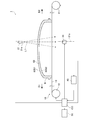
- FIG. 1 shows schematic the inspection apparatus in 1st Embodiment as 1st aspect of this invention. It is a figure which sees the inspection apparatus of FIG. 1 from the downstream side in the 1st transport direction. It is a figure which shows a part of an example of the image imaged by the image pickup unit schematically. It is a figure for demonstrating the propagation of light from a lighting unit. It is a figure which shows the inspection apparatus in the 2nd Embodiment as the 1st aspect of this invention in the same manner as FIG. It is a figure which shows a part of an example of the image of the light from the 2nd illumination part imaged by the image pickup unit schematically.
- FIG. 9 is a view of the inspection device of FIG. 9 viewed from the downstream side in the first transport direction. It is a figure which shows the inspection apparatus in 6th Embodiment as a 2nd aspect of this invention in the same manner as FIG. It is a figure which shows the inspection apparatus in 7th Embodiment as a 2nd aspect of this invention in the same manner as FIG.
- FIG. 1 is a diagram schematically showing an inspection device according to the present embodiment.
- the inspection device 1 of the present embodiment mainly includes a transfer device 10, a lighting unit 21, an imaging unit 30, an inspection unit 40, a display unit 50, and a control unit CO.
- the object to be inspected 60 to be inspected by the inspection device 1 in the present embodiment is an outer cover that transmits light in a vehicle lamp.
- the inspection device 1 inspects the surface of the object to be inspected 60 for defects, such as foreign matter adhering to the surface.
- the object to be inspected 60 is shown by a vertical cross section in FIG.
- the object to be inspected 60 of the present embodiment which is an outer cover, is a plate-shaped member having a light-transmitting property that is convexly curved toward one surface 60S1.
- a translucent rib 61 projecting toward the other surface 60S2 is provided on the outer peripheral edge of the inspected object 60, and the rib 61 extends over the entire outer peripheral edge of the inspected object 60.
- the object to be inspected 60 includes a hard coat layer (not shown) provided on one surface 60S1 side and an anti-fog coat layer (not shown) provided on the other surface 60S2 side.
- the outer surface of the hard coat layer is one surface 60S1 of the object 60 to be inspected
- the outer surface of the antifogging coat layer is the other surface 60S2 of the object 60 to be inspected.
- foreign matter such as dust may adhere to these layers and the foreign matter may become a defect on the surface of the object to be inspected 60.
- an object to be inspected 60 includes one surface 60S1 which is translucent and curves convexly, and the other surface 60S2 which faces the one surface 60S1 and curves concavely. it can. Then, the inspection device 1 of the present embodiment inspects the inspected object 60 for defects on one surface 60S1 and the other surface 60S2.
- the control unit CO includes, for example, integrated circuits such as a microcontroller, an IC (Integrated Circuit), an LSI (Large-scale Integrated Circuit), and an ASIC (Application Specific Integrated Circuit), and an NC (Numerical Control) device. Further, when the NC device is used, the control unit CO may use a machine learning device or may not use a machine learning device. As described below, some configurations of the inspection device 1 are controlled by the control unit CO.
- the transport device 10 is a device that transports the object to be inspected 60 in a predetermined direction.
- the transport device 10 of the present embodiment includes a roller 11, a roller 12, and a transparent strip-shaped support film 13.
- the rollers 11 and 12 are arranged at predetermined intervals in the horizontal direction.
- One end of the support film 13 is wound around one roller 11, the other end of the support film 13 is wound around the other roller 12, and a predetermined tension is applied to the support film 13 between the rollers 11 and 12. ing.
- the object to be inspected 60 is placed on the support film 13 between the rollers 11 and 12 so as to be located on the roller 11 side of the lighting unit 21 and the imaging unit 30 described later.
- the object to be inspected 60 is placed so that the end of the rib 61 of the object to be inspected 60 abuts on the support film 13, and one surface 60S1 of the object to be inspected 60 is the other surface 60S2 in the vertical direction. It is located on the side opposite to the support film 13 side.
- the rollers 11 and 12 rotate, the object to be inspected 60 placed on the support film 13 in this way is substantially horizontal from one roller 11 side in the first transport direction D1 to the other roller 12 side. Transported in the direction.
- the rollers 11 and 12 adjust the rotation speed and the rotation direction by a control signal from the control unit CO.
- the transport device 10 can transport the object to be inspected 60 in the second transport direction D2 which is opposite to the first transport direction D1 by reversing the rotation directions of the rollers 11 and 12.
- Examples of the support film 13 include a resin film.
- the transport device 10 only needs to be able to transport the object to be inspected 60 in a predetermined direction, and the configuration of the transport device 10 is not particularly limited.
- the transport device 10 may be composed of a translucent jig that supports the object to be inspected 60 and a transport mechanism that transports the jig.
- the transport mechanism may be configured to include two linear actuators arranged so as to extend substantially parallel to one side and the other side with respect to the jig.
- the transport mechanism may be a robot arm, and in this case, the robot arm may support the object to be inspected 60.
- the lighting unit 21 of this embodiment is arranged below the support film 13 between the rollers 11 and 12.
- the lighting unit 21 irradiates the other surface 60S2 of the object to be inspected 60 conveyed by the conveying device 10 with light L1 via the support film 13. That is, it can be understood that the lighting unit 21 is arranged on the other surface 60S2 side with the object to be inspected 60 as a reference and irradiates the other surface 60S2 with light L1.
- FIG. 2 is a view of the inspection device 1 of FIG. 1 as viewed from the downstream side of the first transport direction D1.
- the object to be inspected 60 is shown by a vertical cross section. Further, in FIG.
- the light L1 emitted from the lighting unit 21 is indicated by a chain double-dashed line.
- the illumination unit 21 of the present embodiment is one line illumination composed of a plurality of LEDs arranged in parallel in a direction substantially perpendicular and substantially horizontal to the first transport direction D1.
- the straight line 21a parallel to the optical axis of the lighting unit 21 and passing through the light emitting surface 21e of the lighting unit 21 is substantially parallel to the vertical direction, and the light L1 emitted from the lighting unit 21 is white. Will be done.
- the straight line 21a may be non-parallel to the vertical direction.
- the object to be inspected 60 has translucency as described above, such light L1 emitted from the lighting unit 21 is the object to be inspected from the other surface 60S2 side of the object to be inspected 60 toward the one surface 60S1 side. It transmits 60. Since the illumination unit 21 is line illumination as described above, the portion of the object to be inspected 60 through which the light L1 from the illumination unit 21 is transmitted has a line shape extending in a direction substantially perpendicular to the first transport direction D1. The lighting unit 21 switches between light emission and non-light emission according to a control signal from the control unit CO.
- the imaging unit 30 of the present embodiment is arranged above the object to be inspected 60 and images the light L1 from the lighting unit 21 that passes through the object to be inspected 60. That is, the image pickup unit 30 images the light L1 from the illumination unit 21 which is arranged on one surface 60S1 side with the inspected object 60 as a reference and passes through the inspected object 60.
- the image pickup unit 30 is a line sensor camera, is located substantially directly above the lighting unit 21, and intersects the straight line 21a.
- the imaging unit 30 is located at a portion where the imaging range extends in a direction substantially perpendicular to the first transport direction D1 and the imaging range is transmitted by the light L1 from the lighting unit 21 in the object 60 to be inspected or near the portion. Arranged to do so.
- the control unit CO controls the image pickup unit 30 to image the light transmitted through the object to be inspected 60 conveyed to the image pickup unit 30 at predetermined time intervals, and the entire one surface 60S1 of the object to be inspected 60.
- the inspection unit 40 is made to output a two-dimensional image including the above. Further, the control unit CO controls the lighting unit 21 so that the lighting unit 21 does not emit the light L1.
- the imaging unit 30 may output the one-dimensional images captured at predetermined time intervals to the inspection unit 40, respectively. In this case, the inspection unit 40, which will be described later, generates a two-dimensional image including the entire one surface 60S1 from the plurality of one-dimensional images input to the inspection unit 40.
- the inspection unit 40 of the present embodiment determines the presence or absence of defects on one surface 60S1 and the other surface 60S2 of the object to be inspected 60 based on the two-dimensional image input from the image pickup unit 30.
- the determination by the inspection unit 40 is to change the signal output from the inspection unit 40 to the control unit CO based on the two-dimensional image.
- the specific determination by the inspection unit 40 will be described later.
- As a configuration of such an inspection unit 40 for example, a configuration similar to that of the control unit CO can be mentioned.
- the display unit 50 displays the inspection result based on the determination by the inspection unit 40 whether or not there is a defect.
- a liquid crystal display can be mentioned.
- the object to be inspected 60 is placed on the support film 13 between the rollers 11 and 12 of the transport device 10 so as to be located on the roller 11 side of the lighting unit 21 and the imaging unit 30.
- the control unit CO controls the lighting unit 21 to emit light L1 to the lighting unit 21.
- the control unit CO controls the transport device 10 to cause the transport device 10 to transport the object 60 to be inspected in the first transport direction D1. Therefore, the lighting unit 21 irradiates the other surface 60S2 of the object to be inspected 60 transported in the first transport direction D1 by the transport device 10 with the light L1 via the support film 13.
- the control unit CO controls the image pickup unit 30 to cause the image pickup unit 30 to image the light L1 from the illumination unit 21 transmitted through the object to be inspected 60 conveyed in the first transport direction D1 at predetermined time intervals.
- the inspection unit 40 is made to output a two-dimensional image including the entire one surface 60S1 of the object to be inspected 60.
- FIG. 3 is a diagram schematically showing a part of an example of an image captured by the imaging unit 30.
- the dark portion 72 is hatched.
- the inspection unit 40 of the present embodiment extracts a region having a brightness value lower than a predetermined threshold value in the image captured by the imaging unit 30, and calculates the area of the extracted region. Then, when at least one of the calculated areas is larger than a predetermined area, a signal indicating that there is a defect is output to the control unit CO. On the other hand, the inspection unit 40 outputs a signal indicating that there is no defect to the control unit CO when all the calculated areas are smaller than the predetermined area or the area is not extracted. In this way, the inspection unit 40 determines the presence or absence of defects on one surface 60S1 and the other surface 60S2 of the object to be inspected 60 based on the image captured by the image pickup unit 30.
- the inspection unit 40 may be able to determine the presence or absence of defects on one surface 60S1 and the other surface 60S2 of the object to be inspected 60 based on the image captured by the image pickup unit 30. For example, the inspection unit 40 performs a binarization process on a two-dimensional image input from the imaging unit 30 using a predetermined threshold value, and in the binarized image, a region having a brightness value lower than the predetermined threshold value. May be extracted. Further, the inspection unit 40 calculates the area of the extracted area and the maximum width of the area, and when the calculated area is larger than the predetermined area and the calculated width is larger than the predetermined width, there is a defect. The indicated signal may be output to the control unit CO.
- the control unit CO outputs a control signal corresponding to the signal input from the inspection unit 40 to the display unit 50, and causes the display unit 50 to display the inspection result.
- the inspection device 1 of the present embodiment inspects the presence or absence of defects on one surface 60S1 and the other surface 60S2 of the object to be inspected 60.
- the control unit CO controls the transport device 10 to cause the transport device 10 to transport the object 60 to be inspected in the second transport direction D2 opposite to the first transport direction D1, and the inspected object 60 is transported to the subject 60.
- the inspection object 60 is returned to the position where it is placed on the transfer device 10. Therefore, the position of the object to be inspected 60 before the inspection and the position of the object to be inspected 60 after the inspection are substantially the same. Therefore, for example, a worker who places the inspected object 60 on the transport device 10 of the inspection device 1 can accommodate the inspected object 60 after the inspection without moving.
- the transport device 10 does not have to transport the object to be inspected 60 in the second transport direction D2.
- a rib 61 protruding toward the other surface 60S2 is provided on the outer peripheral edge of the object 60 to be inspected, which is an outer cover. Therefore, depending on the direction of light irradiation on the object 60 to be inspected, the light may be reflected at the boundary between the rib 61 and the other surface 60S2, the rib 61, or the like, and the reflected light may be reflected in the image.
- the defect may not be detected by the light, or the light may be erroneously detected as a defect, and the detection accuracy of the defect tends to decrease.
- the inspection device 1 of the present embodiment includes a lighting unit 21, an imaging unit 30, and an inspection unit 40.
- the lighting unit 21 includes one surface 60S1 that is curved in a convex shape and the other surface 60S2 that is curved in a concave shape facing the one surface 60S1 and has a translucent object 60 as a reference.
- the other surface 60S2 is irradiated with light L1.
- the image pickup unit 30 is arranged on one surface 60S1 side with reference to the object 60 to be inspected, and images the light L1 from the illumination unit 21 transmitted through the object 60 to be inspected.
- the inspection unit 40 determines the presence or absence of defects in the object to be inspected 60 based on the image captured by the image pickup unit 30.
- the lighting unit 21 irradiates the other surface 60S2, which is curved in a concave shape, with light L1. Further, a rib 61 protruding from the other surface 60S2 is provided on the outer peripheral edge of the object to be inspected 60. Therefore, as shown in FIG. 4, a part of the light L1 from the lighting unit 21 may be reflected by the boundary between the rib 61 and the other surface 60S2 or the rib 61 and directed toward the other surface 60S2. In this way, a part of the light L1a directed to the other surface 60S2 is reflected by the other surface 60S2.
- the image pickup unit 30 is arranged on one surface 60S1 side with reference to the object 60 to be inspected, so that the light reflected by the other surface 60S2 is the image pickup unit. Incident at 30 is suppressed. Further, the other part of the light L1a directed to the other surface 60S2 is incident on the object to be inspected 60 from the other surface 60S2 and emitted from the one surface 60S1. In the inspection device 1 of the present embodiment, since one surface 60S1 is curved in a convex shape as described above, the light incident on the object 60 to be inspected from the other surface 60S2 is diffused from the one surface 60S1.
- the light can be emitted as such, and the light is suppressed from entering the image pickup unit 30. Therefore, the light emitted from the illumination unit 21 at the boundary between the rib 61 and the other surface 60S2 and reflected by the rib 61 is difficult to be reflected in the image captured by the imaging unit 30. Therefore, in the inspection device 1 of the present embodiment, even when the rib 61 protruding from the other surface 60S2 is provided on the outer peripheral edge of the object 60 to be inspected, the inspection device 1 which is the surface of the object 60 to be inspected has the one surface 60S1 or the like. It is possible to suppress a decrease in the detection accuracy of defects on the other surface 60S2.
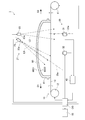
- FIG. 5 is a diagram showing the inspection device according to the second embodiment of the present invention in the same manner as in FIG.
- the inspection device 1 of the present embodiment is mainly different from the inspection device 1 of the first embodiment in that the lighting unit 21 has a first lighting unit 23 and a second lighting unit 25.
- the light L3 emitted from the first illumination unit 23 and the light L5 emitted from the second illumination unit 25 are shown by a chain double-dashed line.
- the first lighting unit 23 in this embodiment has the same configuration as the lighting unit 21 in the first embodiment. Therefore, the first illumination unit 23 of the present embodiment is arranged below the support film 13 between the rollers 11 and 12, and is composed of a plurality of LEDs arranged in parallel in a direction substantially perpendicular and substantially horizontal to the first transport direction D1. It is considered to be composed of line lighting. Further, the first straight line 23a parallel to the optical axis of the first illumination unit 23 and passing through the light emitting surface 23e of the first illumination unit 23 is substantially parallel to the vertical direction, and the imaging unit 30 intersects with the first straight line 23a. There is.
- the first illumination unit 23 irradiates the other surface 60S2 of the object to be inspected 60 conveyed by the conveying device 10 with light L3 via the support film 13, and the light L3 is on the other surface 60S2 side of the object to be inspected 60.
- the object to be inspected 60 is transmitted from the surface toward one surface 60S1 side.
- the portion of the object to be inspected 60 through which the light L3 from the first illumination unit 23 transmits is a line extending in a direction substantially perpendicular to the first transport direction D1.
- the second illumination unit 25 of the present embodiment is arranged below the support film 13 between the rollers 11 and 12 on the roller 11 side of the first illumination unit 23. Similar to the first illumination unit 23, the second illumination unit 25 is line illumination composed of a plurality of LEDs arranged in parallel in a direction substantially perpendicular and substantially horizontal to the first transport direction D1.
- the second straight line 25a which is parallel to the optical axis of the second lighting unit 25 and passes through the light emitting surface 25e of the second lighting unit 25, extends in the vertical direction, but is inclined upward toward the roller 12. , Non-parallel to the first straight line 23a.
- the second straight line 25a passes between the image pickup unit 30 and the roller 12 and does not intersect with the image pickup unit 30.
- the second illumination unit 25 irradiates the other surface 60S2 of the object to be inspected 60 conveyed by the conveying device 10 with light L5 via the support film 13, and this light is emitted from the other surface 60S2 side of the object to be inspected 60.
- the object to be inspected 60 is transmitted toward one surface 60S1 side.
- the portion of the object 60 to be inspected through which the light L5 transmitted from the second illumination unit 25 is transmitted is a line extending in a direction substantially perpendicular to the first transport direction D1, and the light L3 from the first illumination unit 23 in the object 60 to be inspected. Overlaps with the part through which.
- the imaging range of the imaging unit 30 is a portion of the object 60 to be inspected where the portion through which the light L3 from the first illumination unit 23 is transmitted and the portion through which the light L5 from the second illumination unit 25 is transmitted overlap, or a portion where the light L5 is transmitted. It is located in the vicinity of. That is, the first illumination unit 23, the second illumination unit 25, and the imaging unit 30 are arranged so that the imaging range of the imaging unit 30 is located in this way.
- the lighting unit 21 does not emit the light L5 from the second illumination unit 25 when emitting the light L3 from the first illumination unit 23, and does not emit the light L5 from the second illumination unit 25 when emitting the light L5. 1
- Light L3 from the illumination unit 23 is not emitted. That is, the time when the first illuminating unit 23 irradiates the other surface 60S2 of the object to be inspected 60 with the light L3 and the time when the second illuminating unit 25 irradiates the other surface 60S2 of the object to be inspected 60 with the light L5 are mutual. different.
- the object to be inspected 60 is located on the support film 13 between the rollers 11 and 12 of the transport device 10 so as to be located on the roller 11 side of the lighting unit 21 and the imaging unit 30. It is placed in.
- the control unit CO controls the first illumination unit 23 to emit the light L3 to the first illumination unit 23.
- the control unit CO controls the transport device 10 to cause the transport device 10 to transport the object 60 to be inspected in the first transport direction D1. Therefore, the first illumination unit 23 irradiates the other surface 60S2 of the object to be inspected 60 transported in the first transport direction D1 by the transport device 10 with light via the support film 13. At this time, the light L5 from the second illumination unit 25 is not emitted.
- the control unit CO controls the image pickup unit 30 to image the light L3 from the first illumination unit 23 transmitted through the object to be inspected 60 conveyed to the image pickup unit 30 in the first transport direction D1 at predetermined time intervals. Then, the inspection unit 40 is made to output a two-dimensional image including the entire one surface 60S1 of the object to be inspected 60.
- control unit CO controls the second illumination unit 25 to emit the light L5 to the second illumination unit 25 after the above-mentioned imaging by the image pickup unit 30 is completed. Further, the control unit CO controls the transport device 10 to cause the transport device 10 to transport the inspected object 60 in the second transport direction D2, and the inspected object 60 is placed on the transport device 10 by the inspected object 60. Return to the position where it was. Therefore, the second illumination unit 25 irradiates the other surface 60S2 of the object to be inspected 60 transported in the second transport direction D2 by the transport device 10 with the light L5 via the support film 13. At this time, the light L3 from the first illumination unit 23 is not emitted.
- the control unit CO controls the image pickup unit 30 to image the light L5 from the second illumination unit 25 transmitted through the object to be inspected 60 conveyed to the image pickup unit 30 in the second transport direction D2 at predetermined time intervals. Then, the inspection unit 40 is made to output a two-dimensional image including the entire one surface 60S1 of the object to be inspected 60.
- the first straight line 23a and the second straight line 25a are non-parallel to each other. Therefore, in the lighting unit 21, the first lighting unit 23 that irradiates the other surface 60S2 of the object to be inspected 60 with light from the first direction, and the second surface 60S2 of the object to be inspected 60 that is different from the first direction. It can be understood that the second illuminating unit 25 that irradiates the light L5 from the direction is provided. Further, it can be understood that the image pickup unit 30 individually captures the light L3 from the first illumination unit 23 and the light L5 from the second illumination unit 25 that pass through the object to be inspected 60.
- the inspection unit 40 of the present embodiment determines the presence or absence of a defect based on the image captured by the light L3 from the first illumination unit 23, and further, the image obtained by capturing the light L5 from the second illumination unit 25 is obtained. Judge the presence or absence of defects based on this. Specifically, the inspection unit 40 determines the presence or absence of defects from the dark portion in the image in which the light L3 from the first illumination unit 23 is captured.
- the first straight line 23a of the present embodiment intersects with the image pickup unit 30. Therefore, similarly to the first embodiment, the defect can be projected as a dark part in the image of the light L3 from the first illumination unit 23 imaged by the image pickup unit 30.
- the inspection unit 40 of the present embodiment extracts a region having a brightness value lower than a predetermined threshold value in the image of the light L3 from the first illumination unit 23 imaged by the imaging unit 30. , Calculate the area of the extracted area. Then, when the calculated area is larger than the predetermined area, a signal indicating that there is a defect is output to the control unit CO.
- the second straight line 25a does not intersect with the imaging unit 30. Therefore, as compared with the case where the second straight line 25a intersects with the image pickup unit 30, one surface 60S1 and the other surface of the object 60 to be inspected among the light L5 irradiated by the second illumination unit 25 to the object 60 to be inspected. The light transmitted through the object 60 from the other surface 60S2 side toward the one surface 60S1 side without being incident on the defect in the 60S2 is unlikely to be incident on the image pickup unit 30. In the present embodiment, of the light L5 irradiated on the object to be inspected 60 by the second illumination unit 25, the image pickup unit 30 is prevented so that most of the light transmitted through the object to be inspected 60 does not enter the image pickup unit 30.
- FIG. 6 is a diagram schematically showing a part of an example of an image of the light L5 from the second illumination unit 25 imaged by the image pickup unit 30.
- the inspection unit 40 of the present embodiment extracts a region having a brightness value higher than a predetermined threshold value in the image of the light L5 from the second illumination unit 25 imaged by the imaging unit 30, and calculates the area of the extracted region. .. Then, when at least one of the calculated areas is larger than a predetermined area, a signal indicating that there is a defect is output to the control unit CO.
- the inspection unit 40 sends a signal to the control unit CO indicating that there is no defect. Output. In this way, the inspection unit 40 determines the presence or absence of defects based on the image in which the light L3 from the first illumination unit 23 is captured, and further, the image in which the light L5 from the second illumination unit 25 is captured. Judge the presence or absence of defects based on.
- the inspection unit 40 determines the presence or absence of defects based on the image captured by the light L3 from the first illumination unit 23, and further, based on the image captured by the light L5 from the second illumination unit 25. It suffices if the presence or absence of defects can be determined. For example, when the inspection unit 40 determines the presence or absence of a defect based on the image captured by the light L5 from the second illumination unit 25, the inspection unit 40 uses a predetermined threshold value to create a two-dimensional image input from the image pickup unit 30. The binarization process may be performed to extract a region having a brightness value higher than a predetermined threshold value in the binarized image.
- the inspection unit 40 determines the presence or absence of a defect based on the image captured by the light L5 from the second illumination unit 25, the inspection unit 40 calculates and calculates the area of the extracted region and the maximum width of the region. When the area is larger than the predetermined area and the calculated width is larger than the predetermined width, a signal indicating that there is a defect may be output to the control unit CO.
- the control unit CO outputs a control signal corresponding to the signal input from the inspection unit 40 to the display unit 50, and causes the display unit 50 to display the inspection result.
- the inspected object 60 is returned to the position where the inspected object 60 is placed on the transport device 10. Therefore, as in the first embodiment, the position of the inspected object 60 before the inspection and the position of the inspected object 60 after the inspection are substantially the same.
- the lighting unit 21 includes the first lighting unit 23 that irradiates the other surface 60S2 of the object 60 to be illuminated with light L3 from the first direction, and the object 60 to be inspected.
- the other surface 60S2 has a second illumination unit 25 that irradiates the light L5 from a second direction different from the first direction.
- the imaging unit 30 individually captures the light L3 from the first illumination unit 23 and the light L5 from the second illumination unit 25 that pass through the object 60 to be inspected. Further, the image pickup unit 30 intersects the first straight line 23a and does not intersect the second straight line 25a.
- the inspection unit 40 determines the presence or absence of a defect from the dark portion 72 in the image in which the light L3 from the first illumination unit 23 is captured, and the bright portion in the image in which the light L5 from the second illumination unit 25 is captured.
- the presence or absence of defects is determined from 71.
- the inspection device 1 of the present embodiment such a defect can be projected as a bright portion 71 in the image in which the light L5 from the second illumination unit 25 is captured. Therefore, the inspection device 1 of the present embodiment can detect even if the defect is a thin object such as a fibrous foreign substance.
- the timing of irradiating the light L5 is different from each other. Therefore, the light L5 from the second illumination unit 25 is not reflected in the image captured by the light L3 from the first illumination unit 23. Further, the light L3 from the first illumination unit 23 is not reflected in the image captured by the light L5 from the second illumination unit 25. Therefore, the imaging unit 30 does not have, for example, a first imaging unit that images the light L3 from the first illumination unit 23 and a second imaging unit that images the light L5 from the second illumination unit 25. Also, the light L3 from the first illumination unit 23 and the light L5 from the second illumination unit 25 can be individually imaged.
- the light L5 from the second illumination unit 25 is collimated light or light focused on the other surface 60S2 of the object 60 to be inspected. Is preferable. With such a configuration, the brightness of the bright portion 71 when the defect is projected as the bright portion 71 can be increased as compared with the case where the light L5 from the second illumination unit 25 is diffused light, and is fibrous. It is possible to increase the detection accuracy of small defects such as foreign matter.
- FIG. 7 is a diagram showing the inspection device according to the third embodiment of the present invention in the same manner as in FIG.
- the second illumination unit 25 is located on the downstream side of the first illumination unit 23 in the first transport direction D1
- the image pickup unit 30 is the first. It is mainly different from the inspection device 1 of the second embodiment in that it has one imaging unit 31 and a second imaging unit 32.
- the second lighting unit 25 in this embodiment has the same configuration as the second lighting unit 25 in the second embodiment. However, as described above, the second lighting unit 25 is located downstream of the first lighting unit 23 in the first transport direction D1.
- the first imaging unit 31 in this embodiment has the same configuration as the imaging unit 30 in the second embodiment. Therefore, the first imaging unit 31 of the present embodiment is a line sensor camera, is located substantially directly above the first illumination unit 23, and intersects with the first straight line 23a. In the first imaging unit 31, the imaging range extends in a direction substantially perpendicular to the first transport direction D1, and the imaging range is a portion or the portion through which the light L3 from the first illumination unit 23 in the object 60 is transmitted. It is arranged so that it is located in the vicinity of. Then, the first imaging unit 31 images the light L3 from the first illumination unit 23 that passes through the object to be inspected 60.
- the second imaging unit 32 of the present embodiment is a line sensor camera like the first imaging unit 31.
- the second imaging unit 32 is located above the object to be inspected 60 and in a direction parallel to the first transport direction D1 on the roller 12 side of the first illumination unit 23 and the first imaging unit 31, and is located on the first straight line 23a and the first straight line 23a. It does not intersect the second straight line 25a.
- the imaging range extends in a direction substantially perpendicular to the first transport direction D1, and the imaging range is a portion or the portion through which the light L5 from the second illumination unit 25 in the object 60 is transmitted. It is arranged so that it is located in the vicinity of. Then, the second imaging unit 32 images the light L5 from the second illumination unit 25 that passes through the object to be inspected 60.
- the object to be inspected 60 is located on the support film 13 between the rollers 11 and 12 of the transport device 10 so as to be located on the roller 11 side of the lighting unit 21 and the imaging unit 30. It is placed in.
- the control unit CO controls the first illumination unit 23 to emit the light L3 to the first illumination unit 23.
- the control unit CO controls the transport device 10 to cause the transport device 10 to transport the object 60 to be inspected in the first transport direction D1. Therefore, the first illumination unit 23 irradiates the other surface 60S2 of the object to be inspected 60 transported in the first transport direction D1 by the transport device 10 with the light L3 via the support film 13. At this time, the light L5 from the second illumination unit 25 is not emitted.
- the control unit CO controls the first image pickup unit 31 and determines the light L3 from the first illumination unit 23 that passes through the object to be inspected 60 being conveyed to the first image pickup unit 31 in the first transport direction D1. Images are taken at time intervals, and a two-dimensional image including the entire one surface 60S1 of the object to be inspected 60 is output to the inspection unit 40.
- control unit CO controls the second illumination unit 25 to emit the light L5 to the second illumination unit 25 after the above-mentioned imaging by the first imaging unit 31 is completed, as in the second embodiment. .. Further, the control unit CO controls the transport device 10 to cause the transport device 10 to transport the inspected object 60 in the second transport direction D2, and the inspected object 60 is placed on the transport device 10 by the inspected object 60. Return to the position where it was. Therefore, the second illumination unit 25 irradiates the other surface 60S2 of the object to be inspected 60 transported in the second transport direction D2 by the transport device 10 with the light L5 via the support film 13. At this time, the light L3 from the first illumination unit 23 is not emitted.
- the control unit CO controls the second image pickup unit 32 and determines the light L5 from the second illumination unit 25 that passes through the object to be inspected 60 being conveyed to the second image pickup unit 32 in the second transport direction D2. Images are taken at time intervals, and a two-dimensional image including the entire one surface 60S1 of the object to be inspected 60 is output to the inspection unit 40.
- the first imaging unit 31 images the light L3 from the first illumination unit 23 that passes through the object 60 to be inspected, and the second imaging unit 32 transmits the light L3 that passes through the object 60 to be inspected.
- the light L5 from 25 is imaged.
- the first straight line 23a of the present embodiment intersects with the first imaging unit 31. Therefore, similarly to the second embodiment, the defect of the object to be inspected 60 can be projected as a dark part in the image of the light L3 from the first illumination unit 23 imaged by the first imaging unit 31. Further, the second straight line 25a does not intersect with the second imaging unit 32.
- the light L5 irradiated on the object to be inspected 60 by the second illumination unit 25 the light L5 is transmitted through the object to be inspected 60 without being incident on the defect of the object to be inspected 60.
- the position and orientation of the second illumination unit 25 with respect to the second image pickup unit 32 are adjusted so that most of the light does not enter the second image pickup unit 32. Therefore, in the image of the light L5 from the second illumination unit 25 imaged by the second imaging unit 32, the defect can be projected as a bright portion surrounded by a dark portion.
- the inspection unit 40 of the present embodiment determines the presence or absence of defects from the dark portion in the image of the light L3 from the first illumination unit 23 imaged by the first imaging unit 31, and further 2 The presence or absence of defects is determined from the bright portion in the image of the light L5 from the second illumination unit 25 captured by the imaging unit 32.
- control unit CO outputs a control signal corresponding to the signal input from the inspection unit 40 to the display unit 50, and causes the display unit 50 to display the inspection result.
- the inspected object 60 is returned to the position where the inspected object 60 is placed on the transport device 10. Therefore, as in the first embodiment, the position of the inspected object 60 before the inspection and the position of the inspected object 60 after the inspection are substantially the same.
- the inspection device 1 of the present embodiment can detect even a thin defect such as a fibrous foreign substance.
- the image pickup unit 30 transmits the first image pickup unit 31 that captures the light L3 from the first illumination unit 23 that passes through the object to be inspected 60 and the first image pickup unit 31 that passes through the object to be inspected 60. It has a second imaging unit 32 that images the light L5 from the lighting unit 25. Therefore, according to the inspection device 1 of the present embodiment, the degree of freedom in the position and orientation of the second illumination unit 25 with respect to the object to be inspected 60 is increased as compared with the case where the image pickup unit 30 does not have the second image pickup unit 32. This can be improved, and the light L5 from the second illumination unit 25 that passes through the object to be inspected 60 can easily show defects in the captured image. Therefore, the inspection device 1 of the embodiment can further suppress the decrease in the detection accuracy of the defect of the inspected object 60.
- FIG. 8 is a diagram showing the inspection device according to the fourth embodiment of the present invention in the same manner as in FIG. As shown in FIG. 8, the inspection device 1 of the present embodiment has a third embodiment in that the lighting unit 21 is composed of one lighting unit and the second imaging unit 32 is tilted with respect to the vertical direction. It is mainly different from the form inspection device 1.
- the lighting unit 21 of the present embodiment has the same configuration as the lighting unit 21 of the first embodiment. Therefore, the lighting unit 21 of the present embodiment is arranged below the support film 13 between the rollers 11 and 12, and is composed of a plurality of LEDs arranged in parallel in a direction substantially perpendicular and substantially horizontal to the first transport direction D1. It is said to be line lighting. Further, a straight line 21a parallel to the optical axis of the lighting unit 21 and passing through the emission surface 21e of the lighting unit 21 is substantially parallel to the vertical direction, the first imaging unit 31 intersects the straight line 21a, and the second imaging unit 32 It does not intersect this straight line 21a.
- the portion of the object to be inspected 60 through which the light L1 from the lighting unit 21 is transmitted has a line shape extending in a direction substantially perpendicular to the first transport direction D1.
- the imaging range of the first imaging unit 31 is located at or near a portion of the object 60 to be inspected through which the light L1 from the lighting unit 21 passes.
- the second imaging unit 32 of this embodiment is tilted with respect to the vertical direction.
- the second imaging unit 32 is a portion where the imaging range extends in a direction substantially perpendicular to the first transport direction D1 and the imaging range is transmitted by the light L1 from the lighting unit 21 in the object 60 to be inspected.
- it is tilted in the vertical direction so as to be located near the site. That is, the second imaging unit 32 is arranged so that the imaging range is positioned in this way.
- the object to be inspected 60 is located on the support film 13 between the rollers 11 and 12 of the transport device 10 so as to be located on the roller 11 side of the lighting unit 21 and the imaging unit 30. It is placed in.
- the control unit CO controls the lighting unit 21 to emit light L1 to the lighting unit 21.
- the control unit CO controls the transport device 10 to cause the transport device 10 to transport the object 60 to be inspected in the first transport direction D1. Therefore, the lighting unit 21 irradiates the other surface 60S2 of the object to be inspected 60 transported in the first transport direction D1 by the transport device 10 with light via the support film 13.
- the control unit CO controls the first imaging unit 31 and the second imaging unit 32 to transmit the object to be inspected 60 transported to the first imaging unit 31 and the second imaging unit 32 in the first transport direction D1.
- the light L1 from the lighting unit 21 is imaged at predetermined time intervals, and two-dimensional images including the entire one surface 60S1 of the object to be inspected 60 are output to the inspection unit 40, respectively.
- each of the first imaging unit 31 intersecting the straight line 21a and the second imaging unit 32 not intersecting the straight line 21a captures the light L1 from the illumination unit 21 transmitted through the object 60 to be inspected. To do.
- the image of the light L1 from the lighting unit 21 imaged by the first imaging unit 31 is covered in the same manner as in the third embodiment. Defects in the inspection object 60 can be projected as dark areas. Further, the straight line 21a does not intersect with the second imaging unit 32.
- the light transmitted through the object 60 to be inspected without being incident on the defect of the object 60 to be inspected The position and orientation of the second imaging unit 32 with respect to the lighting unit 21 are adjusted so that most of them do not enter the second imaging unit 32. Therefore, in the image of the light L1 from the illumination unit 21 captured by the second imaging unit 32, the defect can be projected as a bright portion surrounded by a dark portion.
- the inspection unit 40 of the present embodiment determines the presence or absence of defects from the dark portion in the image of the light L1 from the lighting unit 21 imaged by the first imaging unit 31, and further, the second imaging The presence or absence of defects is determined from the bright part in the image of the light L1 from the lighting unit 21 imaged by the unit 32.
- control unit CO outputs a control signal corresponding to the signal input from the inspection unit 40 to the display unit 50, and causes the display unit 50 to display the inspection result. Further, the control unit CO controls the transport device 10 to cause the transport device 10 to transport the object 60 to be inspected in the second transport direction D2 opposite to the first transport direction D1, and the inspected object 60 is transported to the subject 60. The inspection object 60 is returned to the position where it is placed on the transfer device 10. Therefore, the position of the object to be inspected 60 before the inspection and the position of the object to be inspected 60 after the inspection are substantially the same. The control unit CO does not have to transport the object to be inspected 60 to the transport device 10 in the second transport direction D2.
- the inspection device 1 of the present embodiment can detect even a thin defect such as a fibrous foreign substance.
- the image pickup unit 30 transmits the first image pickup unit 31 that captures the light L3 from the first illumination unit 23 that passes through the object to be inspected 60 and the first image pickup unit 31 that passes through the object to be inspected 60. It has a second imaging unit 32 that images the light L5 from the lighting unit 25. Therefore, according to the inspection device 1 of the present embodiment, the degree of freedom in the position and orientation of the second illumination unit 25 with respect to the object to be inspected 60 is increased as compared with the case where the image pickup unit 30 does not have the second image pickup unit 32. This can be improved, and the light L5 from the second illumination unit 25 that passes through the object to be inspected 60 can easily show defects in the captured image. Therefore, the inspection device 1 of the embodiment can further suppress the decrease in the detection accuracy of the defect of the inspected object 60.
- FIG. 9 is a diagram schematically showing an inspection device according to the present embodiment.
- the lighting unit 21 is arranged above the support film 13 between the rollers 11 and 12, and the imaging unit 30 is the support film between the rollers 11 and 12. It is mainly different from the inspection device 1 of the first embodiment in that it is arranged below 13.
- the lighting unit 21 of the present embodiment irradiates the light L1 on one surface 60S1 of the object to be inspected 60 conveyed by the conveying device 10. That is, it can be understood that the lighting unit 21 is arranged on one surface 60S1 side with reference to the object 60 to be inspected and irradiates the light L1 on the one surface 60S1.
- FIG. 10 is a view of the inspection device 1 of FIG. 9 as viewed from the downstream side of the first transport direction D1.
- the object to be inspected 60 is shown by a vertical cross section.
- the light L1 emitted from the lighting unit 21 is indicated by a chain double-dashed line.
- the light L1 transmits the inspected object 60 from one surface 60S1 side of the inspected object 60 toward the other surface 60S2 side.
- the image pickup unit 30 of the present embodiment captures the light L1 from the illumination unit 21 transmitted through the object to be inspected 60 through the support film 13. That is, the image pickup unit 30 images the light L1 from the illumination unit 21 which is arranged on the other surface 60S2 side with the inspected object 60 as a reference and passes through the inspected object 60.
- the image pickup unit 30 is a line sensor camera, is located substantially directly below the lighting unit 21, and intersects the straight line 21a.
- the imaging unit 30 is located at a portion where the imaging range extends in a direction substantially perpendicular to the first transport direction D1 and the imaging range is transmitted by the light L1 from the lighting unit 21 in the object 60 to be inspected or near the portion. Arranged to do so.
- the control unit CO controls the image pickup unit 30 to image the light transmitted through the object to be inspected 60 conveyed to the image pickup unit 30 at predetermined time intervals, and the entire other surface 60S2 of the object to be inspected 60.
- the inspection unit 40 is made to output a two-dimensional image including the above.
- the object to be inspected 60 is located on the support film 13 between the rollers 11 and 12 of the transport device 10 so as to be located on the roller 11 side of the lighting unit 21 and the imaging unit 30. It is placed in.
- the control unit CO controls the lighting unit 21 to emit light L1 to the lighting unit 21.
- the control unit CO controls the transport device 10 to cause the transport device 10 to transport the object 60 to be inspected in the first transport direction D1. Therefore, the lighting unit 21 irradiates the light L1 on one surface 60S1 of the object to be inspected 60 transported in the first transport direction D1 by the transport device 10.
- the control unit CO controls the image pickup unit 30 to cause the image pickup unit 30 to image the light L1 from the illumination unit 21 transmitted through the object to be inspected 60 conveyed in the first transport direction D1 at predetermined time intervals.
- the inspection unit 40 is made to output a two-dimensional image including the entire other surface 60S2 of the object to be inspected 60.
- defects can be projected as dark areas 72 surrounded by bright areas 71 in light images.
- the inspection unit 40 of the present embodiment determines the presence or absence of defects on one surface 60S1 and the other surface 60S2 of the object to be inspected 60 based on the image captured by the image pickup unit 30 in the same manner as in the first embodiment. ..
- the control unit CO outputs a control signal corresponding to the signal input from the inspection unit 40 to the display unit 50, and causes the display unit 50 to display the inspection result. Further, the control unit CO controls the transport device 10 to return the inspected object 60 to the position where the inspected object 60 is placed on the transport device 10.
- a rib 61 protruding toward the other surface 60S2 is provided on the outer peripheral edge of the object 60 to be inspected, which is an outer cover. Therefore, a part of the light from the lighting unit 21 may enter the rib 61 and be emitted from the rib 61 toward the image pickup unit 30, or may be reflected by the rib 61 toward the image pickup unit 30. That is, the light transmitted through the rib 61 and the light reflected by the rib 61 may be reflected in the image captured by the image pickup unit 30.
- the light from the rib 61 when the light from the rib 61 overlaps the portion corresponding to the surface 60S1 or the surface 60S2 of the object 60 to be inspected, the light from the rib 61 may not be able to properly inspect the presence or absence of defects in this portion. In this case, there is a concern that the inspection range of defects on the surface of the object to be inspected will be narrowed.
- the inspection device 1 of the present embodiment includes a lighting unit 21, an imaging unit 30, and an inspection unit 40.
- the lighting unit 21 includes one surface 60S1 that is curved in a convex shape and the other surface 60S2 that is curved in a concave shape facing the one surface 60S1 and has a translucent object 60 as a reference.
- One surface 60S1 is irradiated with light L1.
- the image pickup unit 30 is arranged on the other surface 60S2 side with respect to the object to be inspected 60, and images the light L1 from the illumination unit 21 transmitted through the object to be inspected 60.
- the inspection unit 40 determines the presence or absence of defects in the object to be inspected 60 based on the image captured by the image pickup unit 30.
- the imaging unit 30 is arranged on the other surface 60S2 side with respect to the object to be inspected 60. Further, a rib 61 protruding from the other surface 60S2 is provided on the outer peripheral edge of the object to be inspected 60.
- a part of the light emitted from the 60S2 may enter the rib 61 or be reflected by the rib 61 and head toward the image pickup unit 30.
- the light from the rib 61 is directed to the image pickup unit 30, the light is likely to be directed to the image pickup unit 30 without passing through the other surface 60S2 or one surface 60S1 in the vicinity of the rib 61.
- the lighting unit 21 is arranged on the other surface 60S2 side with respect to the object 60 to be inspected and the imaging unit 30 is arranged on the one surface 60S1 side with reference to the object 60 to be inspected.
- the light directed from the rib 61 toward the image pickup unit tends to be directed toward the image pickup unit 30 via the other surface 60S2 or one surface 60S1 in the vicinity of the rib 61.
- the lighting unit 21 is arranged on the other surface 60S2 side with the inspected object 60 as a reference
- the imaging unit 30 is arranged on the one surface 60S1 side with the inspected object 60 as a reference. Even if the light from the rib 61 is directed to the image pickup unit 30, the light does not pass through the rib 61 but passes through the other surface 60S2 or one surface 60S1 in the vicinity of the rib 61. It is hard to overlap with the light heading toward. Therefore, the inspection device 1 of the present embodiment can prevent defects on the other surface 60S2 and one surface 60S1 in the vicinity of the rib 61 from being appropriately detected.
- the inspection device 1 of the present embodiment even if a rib 61 projecting from the other surface 60S2 is provided on the outer peripheral edge of the object to be inspected 60 and light is directed from the rib 61 to the imaging unit 30, the object to be inspected is inspected. It is possible to prevent the inspection range of 60 surface defects from being narrowed.
- FIG. 11 is a diagram showing the inspection device according to the present embodiment in the same manner as in FIG. As shown in FIG. 11, the inspection device 1 of the present embodiment is mainly different from the inspection device 1 of the fifth embodiment in that the lighting unit 21 has the first lighting unit 23 and the second lighting unit 25. In FIG. 11, the light L3 emitted from the first illumination unit 23 and the light L5 emitted from the second illumination unit 25 are shown by a chain double-dashed line.
- the first lighting unit 23 in this embodiment has the same configuration as the lighting unit 21 in the fifth embodiment. Therefore, the first illumination unit 23 of the present embodiment is line illumination composed of a plurality of LEDs arranged above the object to be inspected 60 and arranged in a direction substantially perpendicular and substantially horizontal to the first transport direction D1. It is said that. Further, the first straight line 23a parallel to the optical axis of the first illumination unit 23 and passing through the light emitting surface 23e of the first illumination unit 23 is substantially parallel to the vertical direction, and the imaging unit 30 intersects with the first straight line 23a. There is.
- the first illumination unit 23 irradiates one surface 60S1 of the object to be inspected 60 conveyed by the conveying device 10 with light L3, and the light L3 is from one surface 60S1 side to the other surface 60S2 side of the object to be inspected 60.
- the object to be inspected 60 is transmitted toward.
- the portion of the object to be inspected 60 through which the light L3 from the first illumination unit 23 transmits is a line extending in a direction substantially perpendicular to the first transport direction D1.
- the second lighting unit 25 of the present embodiment is arranged above the object to be inspected 60 and on the roller 11 side of the first lighting unit 23. Similar to the first illumination unit 23, the second illumination unit 25 is line illumination composed of a plurality of LEDs arranged in parallel in a direction substantially perpendicular and substantially horizontal to the first transport direction D1.
- the second straight line 25a which is parallel to the optical axis of the second lighting unit 25 and passes through the light emitting surface 25e of the second lighting unit 25, extends in the vertical direction but is inclined downward toward the roller 12. , Non-parallel to the first straight line 23a.
- the second straight line 25a passes between the image pickup unit 30 and the roller 12 and does not intersect with the image pickup unit 30.
- the second illumination unit 25 irradiates one surface 60S1 of the object to be inspected 60 conveyed by the conveying device 10 with light L5, and the light L5 is from one surface 60S1 side to the other surface 60S2 side of the object to be inspected 60.
- the object to be inspected 60 is transmitted toward.
- the portion of the object 60 to be inspected through which the light L5 transmitted from the second illumination unit 25 is transmitted is a line extending in a direction substantially perpendicular to the first transport direction D1, and the light L3 from the first illumination unit 23 in the object 60 to be inspected. Overlaps with the part through which.
- the imaging range of the imaging unit 30 is a portion of the object 60 to be inspected where the portion through which the light L3 from the first illumination unit 23 is transmitted and the portion through which the light L5 from the second illumination unit 25 is transmitted overlap, or a portion where the light L5 is transmitted. It is located in the vicinity of. That is, the first illumination unit 23, the second illumination unit 25, and the imaging unit 30 are arranged so that the imaging range of the imaging unit 30 is located in this way.
- the lighting unit 21 does not emit the light L5 from the second illumination unit 25 when emitting the light L3 from the first illumination unit 23, and does not emit the light L5 from the second illumination unit 25 when emitting the light L5. 1
- Light L3 from the illumination unit 23 is not emitted. That is, the time when the first illuminating unit 23 irradiates one surface 60S1 of the object to be inspected 60 with light L3 and the time when the second illuminating unit 25 irradiates one surface 60S1 of the object to be inspected 60 with light L5 are mutual. different.
- the object to be inspected 60 is placed on the support film 13 as in the fifth embodiment.
- the control unit CO controls the first illumination unit 23 to emit the light L3 to the first illumination unit 23. Further, the control unit CO controls the transport device 10 to cause the transport device 10 to transport the object 60 to be inspected in the first transport direction D1. Therefore, the first illumination unit 23 irradiates the light L3 on one surface 60S1 of the object to be inspected 60 transported in the first transport direction D1 by the transport device 10. At this time, the light L5 from the second illumination unit 25 is not emitted.
- the control unit CO controls the image pickup unit 30 to image the light L3 from the first illumination unit 23 transmitted through the object to be inspected 60 conveyed to the image pickup unit 30 in the first transport direction D1 at predetermined time intervals. Then, the inspection unit 40 is made to output a two-dimensional image including the entire other surface 60S2 of the object to be inspected 60.
- control unit CO controls the second illumination unit 25 to emit the light L5 to the second illumination unit 25 after the above-mentioned imaging by the image pickup unit 30 is completed. Further, the control unit CO controls the transport device 10 to cause the transport device 10 to transport the inspected object 60 in the second transport direction D2, and the inspected object 60 is placed on the transport device 10 by the inspected object 60. Return to the position where it was. Therefore, the second illumination unit 25 irradiates the one surface 60S1 of the object to be inspected 60 transported in the second transport direction D2 by the transport device 10 with light. At this time, the light L3 from the first illumination unit 23 is not emitted.
- the control unit CO controls the image pickup unit 30 to image the light L5 from the second illumination unit 25 transmitted through the object to be inspected 60 conveyed to the image pickup unit 30 in the second transport direction D2 at predetermined time intervals. Then, the inspection unit 40 is made to output a two-dimensional image including the entire other surface 60S2 of the object to be inspected 60.
- the lighting unit 21 has a first illumination unit 23 that irradiates one surface 60S1 of the object 60 to be illuminated with light L3 from the first direction, and a first surface 60S1 of the object 60 to be inspected 60 that is different from the first direction. It can be understood that it has a second illumination unit 25 that irradiates light L5 from two directions. Further, it can be understood that the image pickup unit 30 individually captures the light L3 from the first illumination unit 23 and the light L5 from the second illumination unit 25 that pass through the object to be inspected 60.
- the inspection unit 40 of the present embodiment determines the presence or absence of a defect based on the image captured by the light L3 from the first illumination unit 23, and further, the image obtained by capturing the light L5 from the second illumination unit 25 is obtained. Judge the presence or absence of defects based on this. Specifically, the inspection unit 40 determines the presence or absence of defects from the dark portion in the image in which the light L3 from the first illumination unit 23 is captured.
- the first straight line 23a of the present embodiment intersects with the image pickup unit 30. Therefore, similarly to the fifth embodiment, the defect can be projected as a dark part in the image of the light L3 from the first illumination unit 23 imaged by the image pickup unit 30.
- the inspection unit 40 of the present embodiment extracts a region having a brightness value lower than a predetermined threshold value in the image of the light L3 from the first illumination unit 23 imaged by the imaging unit 30. , Calculate the area of the extracted area. Then, when the calculated area is larger than the predetermined area, a signal indicating that there is a defect is output to the control unit CO.
- the second straight line 25a does not intersect with the imaging unit 30. Therefore, as compared with the case where the second straight line 25a intersects with the image pickup unit 30, one surface 60S1 and the other surface of the object 60 to be inspected among the light L5 irradiated by the second illumination unit 25 to the object 60 to be inspected. The light transmitted through the object 60 from one surface 60S1 side toward the other surface 60S2 side without being incident on the defect in 60S2 is unlikely to be incident on the image pickup unit 30. In the present embodiment, of the light L5 irradiated on the object to be inspected 60 by the second illumination unit 25, the image pickup unit 30 is prevented so that most of the light transmitted through the object to be inspected 60 does not enter the image pickup unit 30.
- the position and orientation of the second lighting unit 25 with respect to the light are adjusted.
- most of the light L5 emitted by the second illumination unit 25 on the object to be inspected 60 that is incident on the defect is absorbed by the defect or reflected by the defect. Therefore, the light reflected by this defect and transmitted through the object to be inspected 60 can enter the image pickup unit 30. Therefore, as in the second embodiment, as shown in FIG. 6, in the image of the light L5 from the second illumination unit 25 imaged by the image pickup unit 30, the defect is projected as a bright portion 71 surrounded by the dark portion 72. It can be.
- the inspection unit 40 of the present embodiment determines the presence or absence of defects based on the image captured by the light L3 from the first illumination unit 23, and further, the inspection unit 40 from the second illumination unit 25 determines the presence or absence of defects.
- the light L5 determines the presence or absence of defects based on the captured image, and outputs a signal corresponding to the determination to the control unit CO.
- the control unit CO outputs a control signal corresponding to the signal input from the inspection unit 40 to the display unit 50, and causes the display unit 50 to display the inspection result.
- the inspected object 60 is returned to the position where the inspected object 60 is placed on the transport device 10. Therefore, as in the fifth embodiment, the position of the inspected object 60 before the inspection and the position of the inspected object 60 after the inspection are substantially the same.
- the lighting unit 21 includes the first lighting unit 23 that irradiates one surface 60S1 of the object 60 to be light L3 from the first direction, and the object 60 to be inspected.
- One surface 60S1 has a second illumination unit 25 that irradiates light L5 from a second direction different from the first direction.
- the imaging unit 30 individually captures the light L3 from the first illumination unit 23 and the light L5 from the second illumination unit 25 that pass through the object 60 to be inspected. Further, the image pickup unit 30 intersects the first straight line 23a and does not intersect the second straight line 25a.
- the inspection unit 40 determines the presence or absence of a defect from the dark portion 72 in the image in which the light L3 from the first illumination unit 23 is captured, and the bright portion in the image in which the light L5 from the second illumination unit 25 is captured.
- the presence or absence of defects is determined from 71.
- the inspection device 1 of the present embodiment such a defect can be projected as a bright portion 71 in the image in which the light L5 from the second illumination unit 25 is captured. Therefore, the inspection device 1 of the present embodiment can detect even if the defect is a thin object such as a fibrous foreign substance.
- the timing of irradiating the light L5 is different from each other. Therefore, the light L5 from the second illumination unit 25 is not reflected in the image captured by the light L3 from the first illumination unit 23. Further, the light L3 from the first illumination unit 23 is not reflected in the image captured by the light L5 from the second illumination unit 25.
- the imaging unit 30 does not have, for example, a first imaging unit that images the light L3 from the first illumination unit 23 and a second imaging unit that images the light L5 from the second illumination unit 25. Also, the light L3 from the first illumination unit 23 and the light L5 from the second illumination unit 25 can be individually imaged.
- the light L5 from the second illumination unit 25 is collimated light or light focused on one surface 60S1 of the object 60 to be inspected. Is preferable. With such a configuration, the brightness of the bright portion 71 when the defect is projected as the bright portion 71 can be increased as compared with the case where the light L5 from the second illumination unit 25 is diffused light, and is fibrous. It is possible to increase the detection accuracy of small defects such as foreign matter.
- FIG. 12 is a diagram showing the inspection device according to the present embodiment in the same manner as in FIG. As shown in FIG. 12, in the inspection device 1 of the present embodiment, the second illumination unit 25 is located on the downstream side of the first illumination unit 23 in the first transport direction D1, and the image pickup unit 30 is the first. It is mainly different from the inspection device 1 of the sixth embodiment in that it has one imaging unit 31 and a second imaging unit 32.
- the second lighting unit 25 in this embodiment has the same configuration as the second lighting unit 25 in the sixth embodiment. However, as described above, the second lighting unit 25 is located downstream of the first lighting unit 23 in the first transport direction D1.
- the first imaging unit 31 in this embodiment has the same configuration as the imaging unit 30 in the sixth embodiment. Therefore, the first imaging unit 31 of the present embodiment is a line sensor camera, is located substantially directly below the first illumination unit 23, and intersects with the first straight line 23a. In the first imaging unit 31, the imaging range extends in a direction substantially perpendicular to the first transport direction D1, and the imaging range is a portion or the portion through which the light L3 from the first illumination unit 23 in the object 60 is transmitted. It is arranged so that it is located in the vicinity of. Then, the first imaging unit 31 images the light L3 from the first illumination unit 23 that passes through the object to be inspected 60.
- the second imaging unit 32 of the present embodiment is a line sensor camera like the first imaging unit 31.
- the second imaging unit 32 is located below the support film 13 between the rollers 11 and 12 and on the roller 12 side of the first illumination unit 23 and the first imaging unit 31 in a direction parallel to the first transport direction D1. It does not intersect the first straight line 23a and the second straight line 25a.
- the imaging range extends in a direction substantially perpendicular to the first transport direction D1, and the imaging range is a portion or the portion through which the light L5 from the second illumination unit 25 in the object 60 is transmitted. It is arranged so that it is located in the vicinity of. Then, the second imaging unit 32 images the light L5 from the second illumination unit 25 that passes through the object to be inspected 60.
- the object to be inspected 60 is placed on the support film 13 as in the sixth embodiment.
- the control unit CO controls the first illumination unit 23 to emit the light L3 to the first illumination unit 23. Further, the control unit CO controls the transport device 10 to cause the transport device 10 to transport the object 60 to be inspected in the first transport direction D1. Therefore, the first illumination unit 23 irradiates the light L3 on one surface 60S1 of the object to be inspected 60 transported in the first transport direction D1 by the transport device 10. At this time, the light L5 from the second illumination unit 25 is not emitted.
- the control unit CO controls the first image pickup unit 31 and determines the light L3 from the first illumination unit 23 that passes through the object to be inspected 60 being conveyed to the first image pickup unit 31 in the first transport direction D1. Images are taken at time intervals, and a two-dimensional image including the entire other surface 60S2 of the object to be inspected 60 is output to the inspection unit 40.
- control unit CO controls the second illumination unit 25 to emit the light L5 to the second illumination unit 25 after the above-mentioned imaging by the first imaging unit 31 is completed, as in the sixth embodiment. .. Further, the control unit CO controls the transport device 10 to cause the transport device 10 to transport the inspected object 60 in the second transport direction D2, and the inspected object 60 is placed on the transport device 10 by the inspected object 60. Return to the position where it was. Therefore, the second illumination unit 25 irradiates the light L5 on one surface 60S1 of the object to be inspected 60 transported in the second transport direction D2 by the transport device 10. At this time, the light L3 from the first illumination unit 23 is not emitted.
- the control unit CO controls the second image pickup unit 32 and determines the light L5 from the second illumination unit 25 that passes through the object to be inspected 60 being conveyed to the second image pickup unit 32 in the second transport direction D2. Images are taken at time intervals, and a two-dimensional image including the entire other surface 60S2 of the object to be inspected 60 is output to the inspection unit 40.
- the first imaging unit 31 images the light L3 from the first illumination unit 23 that passes through the object 60 to be inspected, and the second imaging unit 32 transmits the light L3 that passes through the object 60 to be inspected.
- the light L5 from 25 is imaged.
- the first straight line 23a of the present embodiment intersects with the first imaging unit 31. Therefore, similarly to the sixth embodiment, the defect of the object to be inspected 60 can be projected as a dark part in the image of the light L3 from the first illumination unit 23 imaged by the first imaging unit 31. Further, the second straight line 25a does not intersect with the second imaging unit 32.
- the light L5 irradiated on the object to be inspected by the second illumination unit 25 the light L5 is transmitted through the object to be inspected 60 without being incident on the defect of the object to be inspected 60.
- the position and orientation of the second illumination unit 25 with respect to the second image pickup unit 32 are adjusted so that most of the light does not enter the second image pickup unit 32. Therefore, in the image of the light L5 from the second illumination unit 25 imaged by the second imaging unit 32, the defect can be projected as a bright portion surrounded by a dark portion.
- the inspection unit 40 of the present embodiment determines the presence or absence of defects from the dark portion in the image of the light L3 from the first illumination unit 23 imaged by the first imaging unit 31, and further, the first 2 The presence or absence of a defect is determined from the bright portion in the image of the light L5 from the second illumination unit 25 imaged by the imaging unit 32.
- control unit CO outputs a control signal corresponding to the signal input from the inspection unit 40 to the display unit 50, and causes the display unit 50 to display the inspection result.
- the inspected object 60 is returned to the position where the inspected object 60 is placed on the transport device 10. Therefore, as in the fifth embodiment, the position of the inspected object 60 before the inspection and the position of the inspected object 60 after the inspection are substantially the same.
- the inspection device 1 of the present embodiment can detect even a thin defect such as a fibrous foreign substance.
- the image pickup unit 30 transmits the first image pickup unit 31 that captures the light L3 from the first illumination unit 23 that passes through the object to be inspected 60 and the first image pickup unit 31 that passes through the object to be inspected 60. It has a second imaging unit 32 that images the light L5 from the lighting unit 25. Therefore, according to the inspection device 1 of the present embodiment, the degree of freedom in the position and orientation of the second illumination unit 25 with respect to the object to be inspected 60 is increased as compared with the case where the image pickup unit 30 does not have the second image pickup unit 32. This can be improved, and the light L5 from the second illumination unit 25 that passes through the object to be inspected 60 can easily show defects in the captured image. Therefore, the inspection device 1 of the embodiment can further suppress the decrease in the detection accuracy of the defect of the inspected object 60.
- FIG. 13 is a diagram showing the inspection device according to the present embodiment in the same manner as in FIG. As shown in FIG. 13, the inspection device 1 of the present embodiment has a seventh embodiment in that the lighting unit 21 is composed of one lighting unit and the second imaging unit 32 is tilted with respect to the vertical direction. It is mainly different from the form inspection device 1.
- the lighting unit 21 of the present embodiment has the same configuration as the lighting unit 21 of the fifth embodiment. Therefore, the illumination unit 21 of the present embodiment is a line illumination composed of a plurality of LEDs arranged above the object to be inspected 60 and arranged in a direction substantially perpendicular and substantially horizontal to the first transport direction D1. To. Further, a straight line 21a parallel to the optical axis of the lighting unit 21 and passing through the emission surface 21e of the lighting unit 21 is substantially parallel to the vertical direction, the first imaging unit 31 intersects the straight line 21a, and the second imaging unit 32 It does not intersect this straight line 21a.
- the portion of the object to be inspected 60 through which the light L1 from the lighting unit 21 is transmitted has a line shape extending in a direction substantially perpendicular to the first transport direction D1.
- the imaging range of the first imaging unit 31 is located at or near a portion of the object 60 to be inspected through which the light L1 from the lighting unit 21 passes.
- the second imaging unit 32 of this embodiment is tilted with respect to the vertical direction.
- the second imaging unit 32 is a portion where the imaging range extends in a direction substantially perpendicular to the first transport direction D1 and the imaging range is transmitted by the light L1 from the lighting unit 21 in the object 60 to be inspected.
- it is tilted in the vertical direction so as to be located near the site. That is, the second imaging unit 32 is arranged so that the imaging range is positioned in this way.
- the object to be inspected 60 is placed on the support film 13 as in the seventh embodiment.
- the control unit CO controls the lighting unit 21 to emit light L1 to the lighting unit 21. Further, the control unit CO controls the transport device 10 to cause the transport device 10 to transport the object 60 to be inspected in the first transport direction D1. Therefore, the lighting unit 21 irradiates the light L1 on one surface 60S1 of the object to be inspected 60 transported in the first transport direction D1 by the transport device 10.
- the control unit CO controls the first imaging unit 31 and the second imaging unit 32 to transmit the object to be inspected 60 transported to the first imaging unit 31 and the second imaging unit 32 in the first transport direction D1.
- the light L1 from the lighting unit 21 is imaged at predetermined time intervals, and a two-dimensional image including the entire other surface 60S2 of the object to be inspected 60 is output to the inspection unit 40, respectively.
- each of the first imaging unit 31 intersecting the straight line 21a and the second imaging unit 32 not intersecting the straight line 21a captures the light L1 from the illumination unit 21 transmitted through the object 60 to be inspected. To do.
- the image of the light L1 from the lighting unit 21 imaged by the first imaging unit 31 is covered in the same manner as in the seventh embodiment. Defects in the inspection object 60 can be projected as dark areas. Further, the straight line 21a does not intersect with the second imaging unit 32.
- the light L1 irradiated on the object 60 to be inspected by the lighting unit 21 the light transmitted through the object 60 to be inspected without being incident on the defect of the object 60 to be inspected.
- the position and orientation of the second imaging unit 32 with respect to the lighting unit 21 are adjusted so that most of them do not enter the second imaging unit 32. Therefore, in the image of the light L1 from the illumination unit 21 captured by the second imaging unit 32, the defect can be projected as a bright portion surrounded by a dark portion.
- the inspection unit 40 of the present embodiment determines the presence or absence of defects from the dark portion in the image of the light L1 from the lighting unit 21 imaged by the first imaging unit 31, and further, the second imaging The presence or absence of defects is determined from the bright part in the image of the light L1 from the lighting unit 21 imaged by the unit 32.
- control unit CO outputs a control signal corresponding to the signal input from the inspection unit 40 to the display unit 50, and causes the display unit 50 to display the inspection result. Further, the control unit CO controls the transport device 10 to cause the transport device 10 to transport the object 60 to be inspected in the second transport direction D2 opposite to the first transport direction D1, and the inspected object 60 is transported to the subject 60. The inspection object 60 is returned to the position where it is placed on the transfer device 10. Therefore, the position of the object to be inspected 60 before the inspection and the position of the object to be inspected 60 after the inspection are substantially the same. The control unit CO does not have to transport the object to be inspected 60 to the transport device 10 in the second transport direction D2.
- the inspection device 1 of the present embodiment can detect even a thin defect such as a fibrous foreign substance.
- the image pickup unit 30 transmits the first image pickup unit 31 that captures the light L3 from the first illumination unit 23 that passes through the object to be inspected 60 and the first image pickup unit 31 that transmits the light L3 that passes through the object to be inspected 60. It has a second imaging unit 32 that captures light from the lighting unit 25. Therefore, according to the inspection device 1 of the present embodiment, the degree of freedom in the position and orientation of the second illumination unit 25 with respect to the object to be inspected 60 is increased as compared with the case where the image pickup unit 30 does not have the second image pickup unit 32. This can be improved, and the light L5 from the second illumination unit 25 that passes through the object to be inspected 60 can easily show defects in the captured image. Therefore, the inspection device 1 of the embodiment can further suppress the decrease in the detection accuracy of the defect of the inspected object 60.
- FIG. 14 is a diagram showing the inspection device according to the present embodiment in the same manner as in FIG. As shown in FIG. 14, the inspection device 1 of the present embodiment is mainly different from the inspection device 1 of the fifth embodiment in that it includes another lighting unit 121 and another imaging unit 130.
- Another lighting unit 121 of the present embodiment has the same configuration as the lighting unit 21 of the first embodiment, and is located below the support film 13 on the downstream side of the lighting unit 21 and the imaging unit 30 in the first transport direction D1. Be placed. Another lighting unit 121 irradiates the other surface 60S2 of the object to be inspected 60 conveyed by the conveying device 10 with light L11 via the support film 13. That is, another lighting unit 121 is arranged on the other surface 60S2 side with reference to the object 60 to be inspected, and irradiates the other surface 60S2 with light L11.
- the straight line 121a which is parallel to the optical axis of another lighting unit 121 and passes through the light emitting surface 121e of another lighting unit 121 is substantially parallel to the straight line 21a, but the straight line 121a and the straight line 21a are not parallel to each other.
- the straight line 121a and the straight line 21a may be non-parallel to the vertical direction.
- the distance between the lighting unit 21 and another lighting unit 121 in the direction parallel to the first transport direction D1 is smaller than the width of the object to be inspected 60 in the direction parallel to the first transport direction D1, but is larger than this width. You may.
- the exit surface 121e of another lighting unit 121 is located closer to the support film 13 than the image pickup unit 30, but the positions of the exit surface 121e and the image pickup unit 30.
- the relationship is not particularly limited.
- Another image pickup unit 130 of the present embodiment has the same configuration as the image pickup unit 30 of the first embodiment, and is above the object to be inspected 60 on the downstream side of the illumination unit 21 and the image pickup unit 30 in the first transport direction D1.
- the light L11 from another lighting unit 121 that is arranged in and passes through the object 60 to be inspected is imaged. That is, another imaging unit 130 images the light L11 from another lighting unit 121 that is arranged on one surface 60S1 side with respect to the object 60 to be inspected and passes through the object 60 to be inspected.
- another imaging unit 130 is a line sensor camera, is located substantially directly above another lighting unit 121, and intersects the straight line 121a. Further, in the vertical direction, another image pickup unit 130 is located on the side opposite to the support film 13 side from the exit surface 21e of the illumination unit 21, but the positional relationship between the other image pickup unit 130 and the exit surface 21e is particularly important. Not limited.
- the object to be inspected 60 is placed on the support film 13 as in the fifth embodiment.
- the control unit CO controls the lighting unit 21 to emit light L1 to the lighting unit 21. Further, the control unit CO controls the transport device 10 to cause the transport device 10 to transport the object 60 to be inspected in the first transport direction D1. Therefore, the lighting unit 21 irradiates the light L1 on one surface 60S1 of the object to be inspected 60 transported in the first transport direction D1 by the transport device 10. At this time, the light L11 from another lighting unit 121 is not emitted.
- the control unit CO controls the image pickup unit 30 to cause the image pickup unit 30 to image the light L1 from the illumination unit 21 transmitted through the object to be inspected 60 conveyed in the first transport direction D1 at predetermined time intervals.
- the inspection unit 40 is made to output a two-dimensional image including the entire other surface 60S2 of the object to be inspected 60.
- control unit CO controls another lighting unit 121 after the above-mentioned imaging by the imaging unit 30 is completed, and emits the light L11 to the other lighting unit 121. Further, the control unit CO controls the transport device 10 to cause the transport device 10 to transport the inspected object 60 in the second transport direction D2, and the inspected object 60 is placed on the transport device 10 by the inspected object 60. Return to the position where it was. Therefore, another lighting unit 121 irradiates the light L11 on one surface 60S1 of the object to be inspected 60 transported in the second transport direction D2 by the transport device 10. At this time, the light L1 from the lighting unit 21 is not emitted.
- the control unit CO controls another image pickup unit 130, and determines the light L11 from another illumination unit 121 that passes through the object to be inspected 60 being conveyed to the other image pickup unit 130 in the second transport direction D2. Images are taken at time intervals, and a two-dimensional image including the entire other surface 60S2 of the object to be inspected 60 is output to the inspection unit 40.
- the imaging unit 30 images the light L1 from the lighting unit 21 that passes through the object 60 to be inspected, and another imaging unit 130 captures the light from another lighting unit 121 that passes through the object 60 to be inspected.
- the L11 is imaged.
- the inspection unit 40 determines the presence or absence of defects from the bright portion in the image of the light L1 from the lighting unit 21 imaged by the imaging unit 30 as in the fifth embodiment. Further, the inspection unit 40 determines the presence or absence of a defect from the bright portion in the image of the light L11 from another lighting unit 121 imaged by another imaging unit 130.
- control unit CO outputs a control signal corresponding to the signal input from the inspection unit 40 to the display unit 50, and causes the display unit 50 to display the inspection result.
- the presence or absence of defects is determined from the image of L11. Therefore, the detection accuracy of defects on the surface of the object to be inspected 60 can be improved as compared with the case where another lighting unit 121 and another imaging unit 130 are not provided.
- the other lighting unit 121 and another imaging unit 130 may be arranged on the upstream side of the lighting unit 21 and the imaging unit 30 in the first transport direction D1. Further, the imaging by another imaging unit 130 may be performed when the object to be inspected 60 is transported in the first transport direction D1. In this case, the other imaging unit 130 is preferably separated from the illumination unit 21 so that the light L1 from the illumination unit 21 does not enter. For example, the distance between the illumination unit 21 and another imaging unit 130 in the direction parallel to the first transport direction D1 is preferably larger than the width of the object to be inspected 60 in the direction parallel to the first transport direction D1. By doing so, it is possible to perform imaging by another imaging unit 130 after the imaging by the imaging unit 30 is completed.
- the lighting unit 21 and another lighting unit 121 alternately irradiate the lights L1 and L11 at predetermined time intervals, and the imaging unit 30 illuminates the light L1 and L11.
- the light L1 may be imaged in synchronization with the unit 21, and another imaging unit 130 may image the light L11 in synchronization with another lighting unit 121.
- any of the second to fourth embodiments can be applied to another lighting unit 121 and another imaging unit 130.
- another lighting unit 121 is a second embodiment shown in FIG. The same configuration as the lighting unit 21 of the above may be used.
- any of the sixth to eighth embodiments can be applied to the lighting unit 21 and the imaging unit 30, and for example, the lighting unit 21 is the same as the lighting unit 21 of the sixth embodiment shown in FIG. It may be configured as.
- the object to be inspected 60 which is an outer cover in which ribs 61 are provided over the entire circumference of the outer peripheral edge
- the object to be inspected 60 may include one surface 60S1 that is translucent and curves in a convex shape, and the other surface 60S2 that faces the one surface 60S1 and curves in a concave shape.
- the rib 61 may be provided on a part of the outer peripheral edge of the object to be inspected 60, or the rib 61 may not be provided on the outer peripheral edge of the object to be inspected 60.
- a part of the object to be inspected 60 may be colorless and transparent, and another part of the object to be inspected 60 may be colored and transparent.
- the lighting unit 21 that irradiates the object to be inspected 60 with white light has been described as an example.
- another lighting unit 121 that irradiates the object to be inspected 60 with white light will be described as an example.
- the color of the light that the lighting unit 21 or another lighting unit 121 irradiates the object to be inspected 60 is not particularly limited. When a part of the object to be inspected 60 is colorless and transparent and another part of the object to be inspected 60 is colored and transparent, the light emitted by the lighting unit 21 or another lighting unit 121 to the object to be inspected 60 is emitted.
- the color is preferably substantially the same as the color of the colored transparent portion of the object to be inspected 60.
- the presence or absence of defects is determined from the dark part in the image in which the light L3 from the first lighting unit 23 is captured, and the light from the second lighting unit 25 is determined.
- the inspection unit 40 for determining the presence or absence of a defect from the bright part in the image in which L5 is captured has been described as an example.
- the illuminating unit 21 irradiates the other surface 60S2 of the object 60 with light L3 from the first direction to the first illuminating unit 23 and the other surface 60S2 from a second direction different from the first direction.
- the inspection unit 40 may determine the presence or absence of the defect based on the image captured by the image pickup unit 30.
- the absorption, reflection, refraction, etc. of light due to the defect of the object 60 to be inspected when the light is irradiated from the first direction is not present. This is different from the case where light is emitted from the second direction.
- defects that were difficult to be projected on the image when the light is irradiated from the first direction are easily projected on the image when the light is irradiated from the second direction, or the light is irradiated from the second direction.
- Defects that were difficult to be projected on the image in such a case may be easily projected on the image when light is irradiated from the second direction. Therefore, such an inspection device can suppress a decrease in the detection accuracy of defects in the object to be inspected 60 as compared with the case where the lighting unit 21 does not have the second illumination unit 25.
- the image pickup unit 30 which is parallel to the optical axis of the second illumination unit 25 and does not intersect with the second straight line 25a passing through the light emitting surface 25e of the second illumination unit 25 has been described as an example. ..
- the imaging unit 30 may intersect the second straight line 25a.
- the inspection unit 40 determines in the image in which the light L5 from the second illumination unit 25 is captured, as in the determination of the presence or absence of defects based on the image in which the light L3 from the first illumination unit 23 is captured. The presence or absence of defects is judged from the dark part.
- the second defect is that the light L3 from the first illumination unit 23 is difficult to be projected on the captured image.
- the light L3 from the first lighting unit 23 has a defect that the light L5 from the lighting unit 25 is easily projected on the captured image and the light L5 from the second lighting unit 25 is difficult to be projected on the captured image.
- the captured image may be easily projected. Therefore, such an inspection device can suppress a decrease in the detection accuracy of defects in the object to be inspected 60 as compared with the case where the lighting unit 21 does not have the second illumination unit 25.
- the second lighting unit 25 located on the upstream side of the first transport direction D1 from the first lighting unit 23 has been described as an example.
- the position of the second illuminating unit 25 with respect to the first illuminating unit 23 is not particularly limited, and the second illuminating unit 25 is connected to the first illuminating unit 23 in the first transport direction D1. It may be located on the downstream side of.
- the second illumination unit 25 is arranged so that the second straight line 25a is inclined upward in the direction opposite to the first transport direction D1, and in the sixth embodiment, the second straight line 25a is arranged.
- the second illumination unit 25 is arranged so as to incline downward in the direction opposite to the first transport direction D1.
- the first straight line 23a may be non-parallel to the vertical direction.
- the first illumination unit 23 and the second illumination unit 25 alternately emit light L3 at predetermined time intervals.
- L5 and the image pickup unit 30 emits light L3 from the first illumination unit 23 and light L3 from the second illumination unit 25 in synchronization with irradiation of light L3 and L5 between the first illumination unit 23 and the second illumination unit 25.
- Light L5 may be imaged alternately.
- the image pickup unit 30 can individually image the light L3 from the first illumination unit 23 and the light L5 from the second illumination unit 25.
- the object to be inspected 60 is transported in only one direction. Therefore, the configuration of the transport device can be simplified as compared with the case where the object to be inspected 60 is transported in a plurality of directions. In addition, the time required for the inspection device 1 to inspect the defect of the object to be inspected 60 can be shortened.
- the second imaging unit 32 receives light from the second illumination unit 25 that passes through the object to be inspected 60 when the object to be inspected 60 is conveyed in the first conveying direction D1.
- L5 may be imaged.
- the light L3 from the first illumination unit 23 is less likely to be incident on the second imaging unit 32, and the light L5 from the second illumination unit 25 is less likely to be incident on the first imaging unit 31.
- the first illumination unit 23 and the second illumination unit 25 are separated from each other, and the first imaging unit 31 and the second imaging unit 32 are separated from each other.
- the imaging unit 30 still emits the light L3 and the light L3 and the second from the first lighting unit 23. 2
- the light L5 from the illumination unit 25 can be imaged individually.
- the object to be inspected 60 is transported in only one direction. Therefore, the configuration of the transport device can be simplified as compared with the case where the object to be inspected 60 is transported in a plurality of directions. In addition, the time required for the inspection device 1 to inspect the defect of the object to be inspected 60 can be shortened.
- the second imaging unit 32 that is parallel to the optical axis of the second illumination unit 25 and does not intersect with the second straight line 25a that passes through the light emitting surface 25e of the second illumination unit 25 is taken as an example. explained. However, in the third embodiment, when the first straight line 23a and the second straight line 25a are non-parallel, the second imaging unit 32 may intersect with the second straight line 25a. In this case, for example, the inspection unit 40 is subjected to the second illumination by the second imaging unit 32 in the same manner as the determination of the presence or absence of defects based on the image in which the light L3 from the first illumination unit 23 is captured by the first imaging unit 31.
- the presence or absence of defects is determined from the dark portion in the image in which the light L5 from the portion 25 is captured. Even with such a configuration, since the first straight line 23a and the second straight line 25a are non-parallel, the second defect is that the light L3 from the first illumination unit 23 is difficult to be projected on the captured image.
- the light L3 from the first lighting unit 23 has a defect that the light L5 from the lighting unit 25 is easily projected on the captured image and the light L5 from the second lighting unit 25 is difficult to be projected on the captured image.
- the captured image may be easily projected. Therefore, such an inspection device can suppress a decrease in the detection accuracy of defects in the object to be inspected 60 as compared with the case where the lighting unit 21 does not have the second illumination unit 25.
- the second imaging unit 32 which is located, has been described as an example.
- the positions of the first illumination unit 23, the second illumination unit 25, the first imaging unit 31, and the second imaging unit 32 in the direction parallel to the first transport direction D1 are particularly limited. It is not something that is done.
- the second illumination unit 25 may be arranged on the upstream side of the first illumination unit 23 in the first transport direction D1.
- the second illumination unit 25 is located upstream of the first illumination unit 23 in the first transport direction D1, and the second imaging unit 32 is located upstream of the first imaging unit 31 in the first transport direction D1. May be. Further, in the third embodiment, the second illumination unit 25 may be arranged so that the second straight line 25a is inclined upward in the direction opposite to the first transport direction D1. Further, in the seventh embodiment, the second illumination unit 25 may be arranged so that the second straight line 25a is inclined downward in the direction opposite to the first transport direction D1. From the viewpoint of suppressing the light L5 from the second illumination unit 25 from entering the first imaging unit 31, the second straight line 25a is from the second illumination unit 25 as in the third and seventh embodiments.
- the image pickup unit 30 is inclined toward the side opposite to the first image pickup section 31 side with respect to the second illumination section 25 in a direction parallel to the first transport direction D1. Further, from the viewpoint of miniaturization, it is preferable to arrange the second illumination unit 25 so that the second straight line 25a passes between the first illumination unit 23 and the first imaging unit 31.
- an inspection device 1 that captures the light L3 from the first lighting unit 23 and then the light L5 from the second lighting unit 25 is taken as an example. explained. However, in the third embodiment, the inspection device 1 may image the light L3 from the first illumination unit 23 after imaging the light L5 from the second illumination unit 25.
- the first illumination unit 23 and the second illumination unit 25 alternately emit light L3 at predetermined time intervals.
- the first imaging unit 31 images the light L3 from the first illumination unit 23 in synchronization with the irradiation of the light L3 of the first illumination unit 23, and the second imaging unit 32 takes the second illumination unit 25.
- the light L5 from the second illumination unit 25 may be imaged in synchronization with the irradiation of the light L5.
- the image pickup unit 30 can individually image the light L3 from the first illumination unit 23 and the light L5 from the second illumination unit 25.
- the object to be inspected 60 is transported in only one direction. Therefore, the configuration of the transport device can be simplified as compared with the case where the object to be inspected 60 is transported in a plurality of directions. In addition, the time required for the inspection device 1 to inspect the defect of the object to be inspected 60 can be shortened.
- the lighting unit 21 which is one line illumination will be described as an example, and the second, third, sixth, and seventh embodiments will be described. Then, the lighting unit 21 having the first lighting unit 23 and the second lighting unit 25, which are line lighting, has been described as an example. Further, in the ninth embodiment, another lighting unit 121, which is one line lighting, has been described as an example.
- the lighting unit 21 and another lighting unit 121 are not particularly limited.
- the lighting unit 21 in the first, fourth, fifth, eighth, and ninth embodiments and another lighting unit 121 in the ninth embodiment may be planar illumination in which LEDs are arranged two-dimensionally. ..
- the first illumination unit 23 and the second illumination unit 25 in the second, third, sixth, and seventh embodiments may be planar illumination in which LEDs are two-dimensionally arranged.
- the image pickup unit 30 which is one line sensor camera will be described as an example, and the third, fourth, seventh and eighth embodiments will be described. Then, the image pickup unit 30 having the first image pickup unit 31 and the second image pickup section 32, which are line sensor cameras, has been described as an example. Further, in the ninth embodiment, another imaging unit 130, which is one line sensor camera, has been described as an example. However, the image pickup unit 30 and another image pickup unit 130 are not particularly limited.
- the image pickup unit 30 in the first, second, fifth, sixth and ninth embodiments and another image pickup unit 130 in the ninth embodiment may be an area sensor camera.
- the first imaging unit 31 and the second imaging unit 32 in the third, fourth, seventh, and eighth embodiments may be area sensor cameras.
- the transport device 10 for moving the object to be inspected 60 with respect to the lighting unit 21 and the imaging unit 30 has been described as an example.
- the transport device may move the lighting unit 21 and the imaging unit 30 with respect to the object to be inspected 60.
- an inspection device capable of suppressing a decrease in the detection accuracy of defects on the surface of the object to be inspected
- the object to be inspected is provided, and according to the second aspect of the present invention, the object to be inspected.
- An inspection device capable of suppressing a narrowing of the inspection range of surface defects is provided, and can be used in fields such as an inspection device for the surface of a lamp.
Abstract
This inspection device (1) comprises: an illumination unit (21) that, in relation to a light-transmitting object (60) under inspection that includes one surface (60S1) bent so as to protrude and another surface (60S2) opposing the one surface (60S1) and bent so as to be recessed, is disposed on the side of the other surface (60S2) and emits light L1 onto the other surface (60S2); an imaging unit (30) that, in relation to the object (60) under inspection, is disposed on the side of the one surface (60S1) and images light (L1) from the illumination unit (21) that has passed through the object (60) under inspection; and an inspection unit (40) that determines whether there is a defect on the one surface (60S1) and the other surface (60S2) of the object (60) under inspection on the basis of an image captured by the imaging unit (30).
Description
本発明は、透光性を有する被検査物の表面の欠陥の有無を検査する検査装置に関する。
The present invention relates to an inspection device for inspecting the presence or absence of defects on the surface of a translucent object to be inspected.
透光性を有する被検査物の表面の欠陥の有無を検査する検査装置において、欠陥の検出確度を向上させるために様々な構成が検討されている。例えば、下記特許文献1には、透光性を有する被検査物に光を照射する照明部と、被検査物を挟んで照明部に対向し被検査物を透過する照明部からの光を撮像する撮像部とを備える検査装置が開示されている。この検査装置では、撮像部によって撮像された画像に基づいて被検査物の表面の欠陥の有無が判断される。
In an inspection device that inspects the presence or absence of defects on the surface of a translucent object to be inspected, various configurations are being studied in order to improve the detection accuracy of defects. For example, Patent Document 1 below captures light from an illuminating unit that irradiates a translucent object to be inspected with light and an illuminating unit that faces the illuminating unit with the inspected object in between and transmits the inspected object. An inspection device including an imaging unit is disclosed. In this inspection device, the presence or absence of defects on the surface of the object to be inspected is determined based on the image captured by the imaging unit.
例えば、灯具における光を透過するアウターカバーの表面に付着する異物等の欠陥を検査するために、上記特許文献1に記載の検査装置を用いることが考えられる。一般的に、アウターカバーは、凸状に湾曲する前面と、この前面と対向し凹状に湾曲する後面と、を含んでいる。また、アウターカバーの外周縁には、後面から突出するリブが設けられる場合があり、例えばこのリブが灯具の他の部材に取り付けられる。
For example, in order to inspect defects such as foreign substances adhering to the surface of the outer cover that transmits light in the lamp, it is conceivable to use the inspection device described in Patent Document 1. Generally, the outer cover includes a convexly curved front surface and a concavely curved rear surface facing the front surface. Further, a rib protruding from the rear surface may be provided on the outer peripheral edge of the outer cover, and for example, this rib is attached to another member of the lamp.
本発明の第1の態様による検査装置は、凸状に湾曲する一方の面と前記一方の面と対向し凹状に湾曲する他方の面とを含み透光性を有する被検査物を基準として前記他方の面側に配置されて前記他方の面に光を照射する照明ユニットと、前記被検査物を基準として前記一方の面側に配置され前記被検査物を透過する前記照明ユニットからの光を撮像する撮像ユニットと、前記撮像ユニットが撮像した画像に基づいて、前記被検査物の前記一方の面及び前記他方の面における欠陥の有無を判断する検査部と、を備えることを特徴とする。
The inspection apparatus according to the first aspect of the present invention is based on a translucent object to be inspected, which includes one surface curved in a convex shape and the other surface facing the one surface and curved in a concave shape. Light from the lighting unit arranged on the other surface side and irradiating the other surface with light and the lighting unit arranged on the one surface side and transmitting the light to be inspected based on the object to be inspected. It is characterized by including an imaging unit for imaging and an inspection unit for determining the presence or absence of defects on the one surface and the other surface of the object to be inspected based on the image captured by the imaging unit.
第1の態様のこの検査装置では、照明ユニットは凹状に湾曲する他方の面に光を照射する。このため、例えば被検査物の外周縁に他方の面から突出するリブが設けられる場合、照明ユニットからの光がこのリブと他方の面との境界やリブ等で反射して他方の面に向かうことがある。このように他方の面に向かう光の一部は、当該他方の面で反射する。第1の態様のこの検査装置では、上記のように撮像ユニットは被検査物を基準として一方の面側に配置されているため、このように他方の面で反射する光が撮像ユニットに入射することが抑制される。また、他方の面に向かう光の他の一部は、他の一部は他方の面から被検査物に入射して一方の面から出射する。第1の態様のこの検査装置では、上記のように一方の面は凸状に湾曲しているため、このように他方の面から被検査物に入射する光を一方の面から拡散するように出射し得、この光が撮像ユニットに入射することが抑制される。このため、照明ユニットからの光がリブと他方の面との境界やリブ等で反射してこの反射した光が撮像ユニットによって撮像された画像に映り込み難い。従って、第1の態様のこの検査装置は、被検査物の外周縁に他方の面から突出するリブが設けられる場合であっても、被検査物の表面の欠陥の検出確度が低下することを抑制し得る。
In this inspection device of the first aspect, the lighting unit irradiates the other surface which is curved in a concave shape with light. Therefore, for example, when a rib projecting from the other surface is provided on the outer peripheral edge of the object to be inspected, the light from the lighting unit is reflected by the boundary between the rib and the other surface, the rib, or the like and heads toward the other surface. Sometimes. In this way, a part of the light directed to the other surface is reflected by the other surface. In this inspection device of the first aspect, since the imaging unit is arranged on one surface side with respect to the object to be inspected as described above, the light reflected on the other surface is incident on the imaging unit in this way. Is suppressed. Further, the other part of the light directed to the other surface is incident on the object to be inspected from the other surface and emitted from the other surface. In this inspection device of the first aspect, since one surface is curved in a convex shape as described above, the light incident on the object to be inspected from the other surface is diffused from one surface in this way. It can be emitted, and the light is suppressed from entering the image pickup unit. Therefore, the light from the lighting unit is reflected by the boundary between the rib and the other surface, the rib, and the like, and it is difficult for the reflected light to be reflected in the image captured by the imaging unit. Therefore, the inspection device of the first aspect reduces the detection accuracy of defects on the surface of the inspected object even when the outer peripheral edge of the inspected object is provided with ribs protruding from the other surface. Can be suppressed.
また、第1の態様の検査装置では、前記照明ユニットは、前記被検査物の前記他方の面に第1方向から光を照射する第1照明部と、前記被検査物の前記他方の面に前記第1方向と異なる第2方向から光を照射する第2照明部とを有し、前記撮像ユニットは、前記被検査物を透過する前記第1照明部からの光及び前記第2照明部からの光をそれぞれ個別に撮像することとしてもよい。
Further, in the inspection device of the first aspect, the lighting unit is attached to the first lighting unit that irradiates the other surface of the object to be inspected with light from the first direction and the other surface of the object to be inspected. It has a second illuminating unit that irradiates light from a second direction different from the first direction, and the imaging unit has light from the first illuminating unit that passes through the object to be inspected and from the second illuminating unit. It is also possible to take an image of each of the lights individually.
第1の態様のこの検査装置では、検査部は、第1方向から被検査物の他方の面に照射されて当該被検査物を透過する第1照明部からの光が撮像された画像に基づいて欠陥の有無を判断する。更に、検査部は、第1方向と異なる第2方向から被検査物の他方の面に照射されて当該被検査物を透過する第2照明部からの光が撮像された画像に基づいて欠陥の有無を判断する。つまり、第1照明部によって被検査物の他方の面に第1方向から光が照射される場合と、第2照明部によって被検査物の他方の面に第1方向と異なる第2方向から光が照射される場合とのそれぞれにおいて、検査部が欠陥の有無を判断する。第1方向と第2方向とは互いに異なるため、第1方向から光が照射される場合における被検査物の欠陥に起因する光の吸収、反射、屈折等は、第2方向から光が照射される場合と異なる。このため、第1方向から光が照射される場合における画像に映し出され難くかった欠陥が第2方向から光が照射される場合における画像に映し出され易くなったり、第2方向から光が照射される場合における画像に映し出され難くかった欠陥が第2方向から光が照射される場合における画像に映し出され易くなったりし得る。このため、第1の態様のこの検査装置は、照明ユニットが第2照明部を有さない場合と比べて、被検査物の欠陥の検出確度が低下することを抑制し得る。
In this inspection device of the first aspect, the inspection unit is based on an image obtained by irradiating the other surface of the object to be inspected from the first direction and capturing the light from the first illumination unit that passes through the object to be inspected. To determine the presence or absence of defects. Further, the inspection unit has a defect based on an image obtained by irradiating the other surface of the object to be inspected from a second direction different from the first direction and light from the second illumination unit passing through the object to be inspected. Judge the presence or absence. That is, there are cases where the first illuminating unit irradiates the other surface of the object to be inspected with light from the first direction, and cases where the second illuminating unit irradiates the other surface of the object to be inspected with light from a second direction different from the first direction. The inspection unit determines the presence or absence of defects in each of the cases where the light is irradiated. Since the first direction and the second direction are different from each other, the light absorption, reflection, refraction, etc. due to the defect of the object to be inspected when the light is irradiated from the first direction is irradiated from the second direction. It is different from the case. For this reason, defects that were difficult to be projected on the image when the light is irradiated from the first direction are easily projected on the image when the light is irradiated from the second direction, or the light is irradiated from the second direction. Defects that were difficult to be projected on the image in such a case may be easily projected on the image when light is irradiated from the second direction. Therefore, the inspection device of the first aspect can suppress a decrease in the detection accuracy of defects of the object to be inspected as compared with the case where the lighting unit does not have the second lighting unit.
また、第1の態様の検査装置では、照明ユニットが第1照明部と第2照明部とを有する場合、前記第1照明部が前記被検査物の前記他方の面に光を照射する時期と前記第2照明部が前記被検査物の前記他方の面に光を照射する時期とが互いに異なることとしてもよい。
Further, in the inspection device of the first aspect, when the lighting unit has the first lighting unit and the second lighting unit, the time when the first lighting unit irradiates the other surface of the object to be inspected with light. The timing at which the second illumination unit irradiates the other surface of the object to be inspected with light may be different from each other.
このような構成にすることで、第1照明部からの光が撮像された画像に第2照明部からの光が映り込むことがない。また、第2照明部からの光が撮像された画像に第1照明部からの光が映り込むことがない。このため、撮像部は、例えば第1照明部からの光を撮像する第1撮像部と、第2照明部からの光を撮像する第2撮像部とを有していなくても、第1照明部からの光及び第2照明部からの光をそれぞれ個別に撮像し得る。
With such a configuration, the light from the second lighting unit is not reflected in the image in which the light from the first lighting unit is captured. Further, the light from the first illumination unit is not reflected in the image in which the light from the second illumination unit is captured. Therefore, even if the imaging unit does not have, for example, a first imaging unit that captures the light from the first illumination unit and a second imaging unit that captures the light from the second illumination unit, the first illumination unit does not have the first illumination unit. The light from the unit and the light from the second illumination unit can be imaged individually.
また、第1の態様の検査装置では、照明ユニットが第1照明部と第2照明部とを有する場合、前記撮像ユニットは、前記第1照明部の光軸と平行で前記第1照明部の光の出射面を通る第1直線と交わるとともに前記第2照明部の光軸と平行で前記第2照明部の光の出射面を通る第2直線と交わらず、前記検査部は、前記第1照明部からの光が撮像された画像における暗部から前記欠陥の無を判断するとともに、前記第2照明部からの光が撮像された画像における明部から前記欠陥の有無の判断することとしてもよい。
Further, in the inspection device of the first aspect, when the lighting unit has the first lighting unit and the second lighting unit, the image pickup unit is parallel to the optical axis of the first lighting unit and of the first lighting unit. The inspection unit crosses the first straight line passing through the light emitting surface and does not intersect with the second straight line passing through the light emitting surface of the second lighting unit in parallel with the optical axis of the second lighting unit. The absence of the defect may be determined from the dark portion in the image in which the light from the illumination unit is captured, and the presence or absence of the defect may be determined from the bright portion in the image in which the light from the second illumination unit is captured. ..
被検査物に欠陥がある場合、被検査物に照射される光のうち欠陥に入射する光の多くは欠陥で吸収されたり欠陥で反射したりする。一方、欠陥に入射しない光の多くは被検査物を透過する。第1の態様のこの検査装置では、上記のように撮像ユニットは第1照明部の光軸と平行で第1照明部の光の出射面を通る第1直線と交わるため、撮像ユニットは、第1照明部からの光のうち欠陥に入射せずに被検査物を透過する光を撮像し得る。このため、第1照明部からの光が撮像された画像において欠陥が暗部として映し出されるようにし得る。また、第1の態様のこの検査装置では、上記のように撮像ユニットは第2照明部の光軸と平行で第2照明部の光の出射面を通る第2直線と交わらないため、撮像ユニットは、第2照明部からの光のうち欠陥に入射して当該欠陥で反射する光を撮像しつつ欠陥に入射せずに被検査物を透過する光を撮像しないようにし得る。このため、第2照明部からの光が撮像された画像において欠陥が明部として映し出されるようにし得る。ところで、光は拡散しながら伝搬するため、欠陥が髪の毛や糸屑等のように細く繊維状のものである場合、このような欠陥は第1照明部からの光が撮像された画像において暗部として映し出されにくい傾向にある。しかし、第1の態様のこの検査装置では、第2照明部からの光が撮像された画像においてこのような欠陥が明部として映し出されるようにし得る。従って、第1の態様のこの検査装置は、欠陥が繊維状の異物等の細いものであっても検出し得る。
When the object to be inspected has a defect, most of the light emitted to the object to be inspected that is incident on the defect is absorbed by the defect or reflected by the defect. On the other hand, most of the light that does not enter the defect passes through the object to be inspected. In this inspection device of the first aspect, as described above, the imaging unit is parallel to the optical axis of the first illumination unit and intersects the first straight line passing through the light emitting surface of the first illumination unit. 1 Of the light from the illumination unit, the light that passes through the object to be inspected without being incident on the defect can be imaged. Therefore, the defect can be projected as a dark part in the image in which the light from the first illumination unit is captured. Further, in this inspection device of the first aspect, as described above, the imaging unit is parallel to the optical axis of the second illumination unit and does not intersect with the second straight line passing through the light emitting surface of the second illumination unit. Can prevent the light transmitted from the object to be inspected from being imaged without being incident on the defect while capturing the light incident on the defect and reflected by the defect among the light from the second illumination unit. Therefore, the defect can be projected as a bright part in the image in which the light from the second illumination unit is captured. By the way, since light propagates while diffusing, when the defect is thin and fibrous such as hair or lint, such a defect is regarded as a dark part in the image in which the light from the first illumination unit is captured. It tends to be difficult to be projected. However, in this inspection device of the first aspect, such defects can be projected as bright parts in the image in which the light from the second illumination unit is captured. Therefore, the inspection device of the first aspect can detect even a fine defect such as a fibrous foreign substance.
或いは、照明ユニットが第1照明部と第2照明部とを有する場合、前記撮像ユニットは、前記被検査物を透過する前記第1照明部からの光を撮像する第1撮像部と、前記被検査物を透過する前記第2照明部からの光を撮像する第2撮像部とを有し、前記第1撮像部は、前記第1照明部の光軸と平行で前記第1照明部の光の出射面を通る第1直線と交わり、前記第2撮像部は、前記第2照明部の光軸と平行で前記第2照明部の光の出射面を通る第2直線と交わらず、前記検査部は、前記第1撮像部によって撮像された画像における暗部から前記欠陥の有無を判断するとともに、前記第2撮像部によって撮像された画像における明部から前記欠陥の有無を判断することとしてもよい。
Alternatively, when the illuminating unit has a first illuminating unit and a second illuminating unit, the imaging unit has a first imaging unit that captures light from the first illuminating unit that passes through the object to be inspected, and the subject. It has a second imaging unit that captures the light from the second illumination unit that passes through the inspection object, and the first imaging unit is parallel to the optical axis of the first illumination unit and the light of the first illumination unit. The second imaging unit intersects with the first straight line passing through the emission surface of the second illumination unit, is parallel to the optical axis of the second illumination unit, and does not intersect with the second straight line passing through the light emission surface of the second illumination unit. The unit may determine the presence or absence of the defect from the dark portion in the image captured by the first imaging unit and may determine the presence or absence of the defect from the bright portion in the image captured by the second imaging unit. ..
第1の態様のこの検査装置では、上記のように第1撮像部は、第1照明部の光軸と平行で第1照明部の光の出射面を通る第1直線と交わる。このため、前述のように第1撮像部によって第1照明部からの光が撮像された画像において欠陥が暗部として映し出されるようにし得る。また、上記のように第2撮像部は、第2照明部の光軸と平行で第2照明部の光の出射面を通る第2直線と交わらない。このため、前述のように第2撮像部によって第2照明部からの光が撮像された画像において欠陥が明部として映し出されるようにし得る。従って、このような構成の検査装置であっても繊維状の異物等の細い欠陥を検出し得る。
In this inspection device of the first aspect, as described above, the first imaging unit intersects the first straight line that is parallel to the optical axis of the first illumination unit and passes through the light emitting surface of the first illumination unit. Therefore, as described above, the defect can be projected as a dark part in the image in which the light from the first illumination unit is captured by the first imaging unit. Further, as described above, the second imaging unit does not intersect the second straight line that is parallel to the optical axis of the second illumination unit and passes through the light emitting surface of the second illumination unit. Therefore, as described above, the defect can be projected as a bright portion in the image in which the light from the second illumination unit is captured by the second imaging unit. Therefore, even an inspection device having such a configuration can detect fine defects such as fibrous foreign matter.
また、第1の態様の検査装置では、撮像部が第1直線と交わるとともに第2直線と交わらない場合、及び、撮像部が第1撮像部と第2撮像部とを有する場合、前記第2照明部からの前記光は、コリメート光または前記被検査物の前記他方の面に集光する光であることとしてもよい。
Further, in the inspection device of the first aspect, when the image pickup unit intersects the first straight line and does not intersect the second straight line, and when the image pickup unit has the first image pickup unit and the second image pickup unit, the second image pickup unit is described. The light from the illumination unit may be collimated light or light focused on the other surface of the object to be inspected.
このような構成にすることで、第2照明部からの光が拡散光である場合と比べて、欠陥が明部として映し出される際の明部の輝度を高くし得、繊維状の異物等の細い欠陥の検出確度を高くし得る。
With such a configuration, the brightness of the bright part when the defect is projected as the bright part can be increased as compared with the case where the light from the second illumination part is diffused light, and fibrous foreign matter or the like can be increased. The detection accuracy of small defects can be increased.
また、第1の態様の検査装置では、前記撮像ユニットは、前記照明ユニットの光軸と平行で前記照明ユニットの光の出射面を通る直線と交わり前記被検査物を透過する前記照明ユニットからの光を撮像する第1撮像部と、前記直線と交わらず前記被検査物を透過する前記照明ユニットからの光を撮像する第2撮像部とを有し、前記検査部は、前記第1撮像部によって撮像された画像における暗部から前記欠陥の有無を判断するとともに、前記第2撮像部によって撮像された画像における明部から前記欠陥の有無を判断することとしてもよい。
Further, in the inspection device of the first aspect, the imaging unit is from the lighting unit that is parallel to the optical axis of the lighting unit, intersects a straight line passing through the light emitting surface of the lighting unit, and transmits the object to be inspected. It has a first imaging unit that captures light and a second imaging unit that captures light from the lighting unit that passes through the object to be inspected without intersecting the straight line. The inspection unit is the first imaging unit. The presence or absence of the defect may be determined from the dark portion in the image captured by the second imaging unit, and the presence or absence of the defect may be determined from the bright portion in the image captured by the second imaging unit.
第1の態様のこの検査装置では、上記のように第1撮像部は、照明ユニットの光軸と平行で照明ユニットの光の出射面を通る直線と交わる。このため、前述のように第1撮像部によって照明ユニットからの光が撮像された画像において欠陥が暗部として映し出されるようにし得る。また、上記のように第2撮像部は、照明ユニットの光軸と平行で照明ユニットの光の出射面を通る直線と交わらない。このため、前述ように第2撮像部によって照明ユニットからの光が撮像された画像において欠陥が明部として映し出されるようにし得る。従って、このような構成の検査装置であっても繊維状の異物等の細い欠陥を検出し得る。
In this inspection device of the first aspect, as described above, the first imaging unit intersects a straight line that is parallel to the optical axis of the lighting unit and passes through the light emitting surface of the lighting unit. Therefore, as described above, the defect can be projected as a dark part in the image in which the light from the lighting unit is captured by the first imaging unit. Further, as described above, the second imaging unit is parallel to the optical axis of the lighting unit and does not intersect with a straight line passing through the light emitting surface of the lighting unit. Therefore, as described above, the defect can be projected as a bright portion in the image in which the light from the lighting unit is captured by the second imaging unit. Therefore, even an inspection device having such a configuration can detect fine defects such as fibrous foreign matter.
本発明の第2の態様による検査装置は、凸状に湾曲する一方の面と前記一方の面と対向し凹状に湾曲する他方の面とを含み透光性を有する被検査物を基準として前記一方の面側に配置されて前記一方の面に光を照射する照明ユニットと、前記被検査物を基準として前記他方の面側に配置され前記被検査物を透過する前記照明ユニットからの光を撮像する撮像ユニットと、前記撮像ユニットが撮像した画像に基づいて、前記被検査物の前記一方の面及び前記他方の面における欠陥の有無を判断する検査部と、を備えることを特徴とする。
The inspection apparatus according to the second aspect of the present invention is based on a translucent object to be inspected, which includes one surface curved in a convex shape and the other surface facing the one surface and curved in a concave shape. Light from a lighting unit arranged on one surface side and irradiating light on the one surface and light from the lighting unit arranged on the other surface side based on the object to be inspected and transmitted through the object to be inspected. It is characterized by including an imaging unit for imaging and an inspection unit for determining the presence or absence of defects on the one surface and the other surface of the object to be inspected based on the image captured by the imaging unit.
例えば、被検査物の外周縁に他方の面から突出するリブが設けられる場合、リブを透過する光やリブで反射する光が撮像部によって撮像される画像に映り込むことがある。このようなリブが設けられるとともに、照明ユニットが被検査物を基準として他方の面側に配置され、撮像ユニットが被検査物を基準として一方の面側に配置される場合、照明ユニットからの光のうちリブから撮像ユニットに向かう光は、リブの近傍における他方の面や一方の面を介して撮像ユニットに向かうようになり易い。この場合、リブから撮像ユニットに向かう光の多くは、リブを介さずにリブの近傍における他方の面や一方の面を介して撮像ユニットに向かう光と重なって撮像ユニットに入射し易い。つまり、撮像部によって撮像される画像において、リブからの光がリブの近傍における他方の面や一方の面と重なり易い。このため、リブから撮像ユニットに向かう光によって、リブの近傍における他方の面や一方の面における欠陥を適切に検出できなくなる傾向がある。一方、第2の態様によるこの検査装置では、上記のように、照明ユニットは被検査物を基準として一方の面側に配置され、撮像ユニットは被検査物を基準として他方の面側に配置される。このため、上記のように被検査物の外周縁に他方の面から突出するリブが設けられる場合、照明ユニットからの光のうち、一方の面から被検査物に入射する光の一部や、一方の面から被検査物に入射して当該被検査物の他方の面から出射する光の一部は、リブに入射したりリブで反射したりして撮像ユニットに向かう場合がある。このようにリブから光が撮像ユニットに向かったとしても、当該光はリブの近傍における他方の面や一方の面を介さずに撮像ユニットに向かい易い。このため、照明ユニットが被検査物を基準として他方の面側に配置され、撮像ユニットが被検査物を基準として一方の面側に配置される場合と比べて、リブから光が撮像ユニットに向かったとしても、当該光は、リブを介さずにリブの近傍における他方の面や一方の面を介して撮像ユニットに向かう光と重なり難く、リブの近傍における他方の面や一方の面における欠陥を適切に検出できなくなることを抑制し得る。従って、第2の態様によるこの検査装置は、被検査物の外周縁に他方の面から突出するリブが設けられて当該リブから光が撮像ユニットに向かったとしても、被検査物の表面の欠陥の検査範囲が狭くなることを抑制し得る。
For example, when a rib protruding from the other surface is provided on the outer peripheral edge of the object to be inspected, the light transmitted through the rib or the light reflected by the rib may be reflected in the image captured by the imaging unit. When such ribs are provided and the lighting unit is arranged on the other surface side with respect to the object to be inspected and the imaging unit is arranged on one surface side with reference to the object to be inspected, the light from the illumination unit is provided. Of these, the light directed from the rib toward the image pickup unit tends to be directed toward the image pickup unit via the other surface or one surface in the vicinity of the rib. In this case, most of the light from the rib toward the image pickup unit is likely to overlap with the light toward the image pickup unit via the other surface or one surface in the vicinity of the rib without passing through the rib and enter the image pickup unit. That is, in the image captured by the imaging unit, the light from the rib tends to overlap the other surface or one surface in the vicinity of the rib. Therefore, the light directed from the rib toward the image pickup unit tends to make it impossible to properly detect defects on the other surface or one surface in the vicinity of the rib. On the other hand, in this inspection device according to the second aspect, as described above, the lighting unit is arranged on one surface side with respect to the object to be inspected, and the imaging unit is arranged on the other surface side with reference to the object to be inspected. To. Therefore, when the ribs protruding from the other surface are provided on the outer peripheral edge of the object to be inspected as described above, a part of the light from the lighting unit that is incident on the object to be inspected from one surface or A part of the light incident on the object to be inspected from one surface and emitted from the other surface of the object to be inspected may be incident on the ribs or reflected by the ribs and directed toward the imaging unit. Even if the light is directed from the rib to the imaging unit in this way, the light tends to be directed to the imaging unit without passing through the other surface or one surface in the vicinity of the rib. Therefore, as compared with the case where the lighting unit is arranged on the other surface side with respect to the object to be inspected and the imaging unit is arranged on one surface side with reference to the object to be inspected, the light is directed from the rib toward the imaging unit. Even so, the light does not easily overlap with the light directed to the imaging unit via the other surface or one surface in the vicinity of the rib without passing through the rib, and causes defects in the other surface or one surface in the vicinity of the rib. It is possible to suppress the inability to detect properly. Therefore, in this inspection device according to the second aspect, even if a rib protruding from the other surface is provided on the outer peripheral edge of the object to be inspected and light is directed to the imaging unit from the rib, a defect on the surface of the object to be inspected is obtained. It is possible to suppress the narrowing of the inspection range of.
また、第2の態様の検査装置では、前記照明ユニットは、前記被検査物の前記一方の面に第1方向から光を照射する第1照明部と、前記被検査物の前記一方の面に前記第1方向と異なる第2方向から光を照射する第2照明部とを有し、前記撮像ユニットは、前記被検査物を透過する前記第1照明部からの光及び前記第2照明部からの光をそれぞれ個別に撮像することとしてもよい。
Further, in the inspection device of the second aspect, the lighting unit is attached to the first lighting unit that irradiates the one surface of the object to be inspected with light from the first direction and the one surface of the object to be inspected. It has a second illuminating unit that irradiates light from a second direction different from the first direction, and the imaging unit has light from the first illuminating unit that passes through the object to be inspected and from the second illuminating unit. It is also possible to take an image of each of the lights individually.
第2の態様によるこの検査装置では、検査部は、第1方向から被検査物の一方の面に照射されて当該被検査物を透過する第1照明部からの光が撮像された画像に基づいて欠陥の有無を判断する。更に、検査部は、第1方向と異なる第2方向から被検査物の一方の面に照射されて当該被検査物を透過する第2照明部からの光が撮像された画像に基づいて欠陥の有無を判断する。つまり、第1照明部によって被検査物の一方の面に第1方向から光が照射される場合と、第2照明部によって被検査物の一方の面に第1方向と異なる第2方向から光が照射される場合とのそれぞれにおいて、検査部が欠陥の有無を判断する。第1方向と第2方向とは互いに異なるため、第1方向から光が照射される場合における被検査物の欠陥に起因する光の吸収、反射、屈折等は、第2方向から光が照射される場合と異なる。このため、第1方向から光が照射される場合における画像に映し出され難くかった欠陥が第2方向から光が照射される場合における画像に映し出され易くなったり、第2方向から光が照射される場合における画像に映し出され難くかった欠陥が第2方向から光が照射される場合における画像に映し出され易くなったりし得る。このため、第2の態様によるこの検査装置は、照明ユニットが第2照明部を有さない場合と比べて、被検査物の欠陥の検出確度が低下することを抑制し得る。
In this inspection device according to the second aspect, the inspection unit is based on an image obtained by irradiating one surface of the object to be inspected from the first direction and capturing light from the first illumination unit that passes through the object to be inspected. To determine the presence or absence of defects. Further, the inspection unit has a defect based on an image in which one surface of the object to be inspected is irradiated from a second direction different from the first direction and the light from the second illumination unit transmitted through the object to be inspected is captured. Judge the presence or absence. That is, when the first illuminating unit irradiates one surface of the object to be inspected with light from the first direction, and when the second illuminating unit irradiates one surface of the object to be inspected with light from a second direction different from the first direction. The inspection unit determines the presence or absence of defects in each of the cases where the light is irradiated. Since the first direction and the second direction are different from each other, the light absorption, reflection, refraction, etc. due to the defect of the object to be inspected when the light is irradiated from the first direction is irradiated from the second direction. It is different from the case. For this reason, defects that were difficult to be projected on the image when the light is irradiated from the first direction are easily projected on the image when the light is irradiated from the second direction, or the light is irradiated from the second direction. Defects that were difficult to be projected on the image in such a case may be easily projected on the image when light is irradiated from the second direction. Therefore, the inspection device according to the second aspect can suppress a decrease in the detection accuracy of a defect of the object to be inspected as compared with the case where the lighting unit does not have the second illumination unit.
また、第2の態様の検査装置では、照明ユニットが第1照明部と第2照明部とを有する場合、前記第1照明部が前記被検査物の前記一方の面に光を照射する時期と前記第2照明部が前記被検査物の前記一方の面に光を照射する時期とが互いに異なることとしてもよい。
Further, in the inspection device of the second aspect, when the lighting unit has the first lighting unit and the second lighting unit, the time when the first lighting unit irradiates the one surface of the object to be inspected with light. The timing at which the second illumination unit irradiates the one surface of the object to be inspected with light may be different from each other.
このような構成にすることで、第1照明部からの光が撮像された画像に第2照明部からの光が映り込むことがない。また、第2照明部からの光が撮像された画像に第1照明部からの光が映り込むことがない。このため、撮像部は、例えば第1照明部からの光を撮像する第1撮像部と、第2照明部からの光を撮像する第2撮像部とを有していなくても、第1照明部からの光及び第2照明部からの光をそれぞれ個別に撮像し得る。
With such a configuration, the light from the second lighting unit is not reflected in the image in which the light from the first lighting unit is captured. Further, the light from the first illumination unit is not reflected in the image in which the light from the second illumination unit is captured. Therefore, even if the imaging unit does not have, for example, a first imaging unit that captures the light from the first illumination unit and a second imaging unit that captures the light from the second illumination unit, the first illumination unit does not have the first illumination unit. The light from the unit and the light from the second illumination unit can be imaged individually.
また、第2の態様の検査装置では、照明ユニットが第1照明部と第2照明部とを有する場合、前記撮像ユニットは、前記第1照明部の光軸と平行で前記第1照明部の光の出射面を通る第1直線と交わるとともに前記第2照明部の光軸と平行で前記第2照明部の光の出射面を通る第2直線と交わらず、前記検査部は、前記第1照明部からの光が撮像された画像における暗部から前記欠陥の無を判断するとともに、前記第2照明部からの光が撮像された画像における明部から前記欠陥の有無の判断することとしてもよい。
Further, in the inspection device of the second aspect, when the lighting unit has the first lighting unit and the second lighting unit, the image pickup unit is parallel to the optical axis of the first lighting unit and of the first lighting unit. The inspection unit crosses the first straight line passing through the light emitting surface and does not intersect with the second straight line passing through the light emitting surface of the second lighting unit in parallel with the optical axis of the second lighting unit. The absence of the defect may be determined from the dark portion in the image in which the light from the illumination unit is captured, and the presence or absence of the defect may be determined from the bright portion in the image in which the light from the second illumination unit is captured. ..
被検査物に欠陥がある場合、被検査物に照射される光のうち欠陥に入射する光の多くは欠陥で吸収されたり欠陥で反射したりする。一方、欠陥に入射しない光の多くは被検査物を透過する。第2の態様によるこの検査装置では、上記のように撮像ユニットは第1照明部の光軸と平行で第1照明部の光の出射面を通る第1直線と交わるため、撮像ユニットは、第1照明部からの光のうち欠陥に入射せずに被検査物を透過する光を撮像し得る。このため、第1照明部からの光が撮像された画像において欠陥が暗部として映し出されるようにし得る。また、第2の態様によるこの検査装置では、上記のように撮像ユニットは第2照明部の光軸と平行で第2照明部の光の出射面を通る第2直線と交わらないため、撮像ユニットは、第2照明部からの光のうち欠陥に入射して当該欠陥で反射する光を撮像しつつ欠陥に入射せずに被検査物を透過する光を撮像しないようにし得る。このため、第2照明部からの光が撮像された画像において欠陥が明部として映し出されるようにし得る。ところで、光は拡散しながら伝搬するため、欠陥が髪の毛や糸屑等のように細く繊維状のものである場合、このような欠陥は第1照明部からの光が撮像された画像において暗部として映し出されにくい傾向にある。しかし、第2の態様によるこの検査装置では、第2照明部からの光が撮像された画像においてこのような欠陥が明部として映し出されるようにし得る。従って、この検査装置は、欠陥が繊維状の異物等の細いものであっても検出し得る。
When the object to be inspected has a defect, most of the light emitted to the object to be inspected that is incident on the defect is absorbed by the defect or reflected by the defect. On the other hand, most of the light that does not enter the defect passes through the object to be inspected. In this inspection device according to the second aspect, as described above, the imaging unit is parallel to the optical axis of the first illumination unit and intersects the first straight line passing through the light emitting surface of the first illumination unit. 1 Of the light from the illumination unit, the light that passes through the object to be inspected without being incident on the defect can be imaged. Therefore, the defect can be projected as a dark part in the image in which the light from the first illumination unit is captured. Further, in this inspection device according to the second aspect, as described above, the imaging unit is parallel to the optical axis of the second illumination unit and does not intersect with the second straight line passing through the light emitting surface of the second illumination unit. Can prevent the light transmitted from the object to be inspected from being imaged without being incident on the defect while capturing the light incident on the defect and reflected by the defect among the light from the second illumination unit. Therefore, the defect can be projected as a bright part in the image in which the light from the second illumination unit is captured. By the way, since light propagates while diffusing, when the defect is thin and fibrous such as hair or lint, such a defect is regarded as a dark part in the image in which the light from the first illumination unit is captured. It tends to be difficult to be projected. However, in this inspection device according to the second aspect, such defects can be projected as bright parts in the image in which the light from the second illumination unit is captured. Therefore, this inspection device can detect even a fine defect such as a fibrous foreign substance.
或いは、照明ユニットが第1照明部と第2照明部とを有する場合、前記撮像ユニットは、前記被検査物を透過する前記第1照明部からの光を撮像する第1撮像部と、前記被検査物を透過する前記第2照明部からの光を撮像する第2撮像部とを有し、前記第1撮像部は、前記第1照明部の光軸と平行で前記第1照明部の光の出射面を通る第1直線と交わり、前記第2撮像部は、前記第2照明部の光軸と平行で前記第2照明部の光の出射面を通る第2直線と交わらず、前記検査部は、前記第1撮像部によって撮像された画像における暗部から前記欠陥の有無を判断するとともに、前記第2撮像部によって撮像された画像における明部から前記欠陥の有無を判断することとしてもよい。
Alternatively, when the illuminating unit has a first illuminating unit and a second illuminating unit, the imaging unit has a first imaging unit that captures light from the first illuminating unit that passes through the object to be inspected, and the subject. It has a second imaging unit that captures the light from the second illumination unit that passes through the inspection object, and the first imaging unit is parallel to the optical axis of the first illumination unit and the light of the first illumination unit. The second imaging unit intersects with the first straight line passing through the emission surface of the second illumination unit, is parallel to the optical axis of the second illumination unit, and does not intersect with the second straight line passing through the light emission surface of the second illumination unit. The unit may determine the presence or absence of the defect from the dark portion in the image captured by the first imaging unit and may determine the presence or absence of the defect from the bright portion in the image captured by the second imaging unit. ..
第2の態様によるこの検査装置では、上記のように第1撮像部は、第1照明部の光軸と平行で第1照明部の光の出射面を通る第1直線と交わる。このため、前述のように第1撮像部によって第1照明部からの光が撮像された画像において欠陥が暗部として映し出されるようにし得る。また、上記のように第2撮像部は、第2照明部の光軸と平行で第2照明部の光の出射面を通る第2直線と交わらない。このため、前述のように第2撮像部によって第2照明部からの光が撮像された画像において欠陥が明部として映し出されるようにし得る。従って、このような構成の検査装置であっても繊維状の異物等の細い欠陥を検出し得る。
In this inspection device according to the second aspect, as described above, the first imaging unit intersects the first straight line that is parallel to the optical axis of the first illumination unit and passes through the light emitting surface of the first illumination unit. Therefore, as described above, the defect can be projected as a dark part in the image in which the light from the first illumination unit is captured by the first imaging unit. Further, as described above, the second imaging unit does not intersect the second straight line that is parallel to the optical axis of the second illumination unit and passes through the light emitting surface of the second illumination unit. Therefore, as described above, the defect can be projected as a bright portion in the image in which the light from the second illumination unit is captured by the second imaging unit. Therefore, even an inspection device having such a configuration can detect fine defects such as fibrous foreign matter.
また、第2の態様の検査装置では、撮像部が第1直線と交わるとともに第2直線と交わらない場合、及び、撮像部が第1撮像部と第2撮像部とを有する場合、前記第2照明部からの前記光は、コリメート光または前記被検査物の前記他方の面に集光する光であることとしてもよい。
Further, in the inspection device of the second aspect, when the image pickup unit intersects the first straight line and does not intersect the second straight line, and when the image pickup unit has the first image pickup unit and the second image pickup unit, the second image pickup unit is described. The light from the illuminating unit may be collimated light or light focused on the other surface of the object to be inspected.
このような構成にすることで、第2照明部からの光が拡散光である場合と比べて、欠陥が明部として映し出される際の明部の輝度を高くし得、繊維状の異物等の細い欠陥の検出確度を高くし得る。
With such a configuration, the brightness of the bright part when the defect is projected as the bright part can be increased as compared with the case where the light from the second illumination part is diffused light, and fibrous foreign matter or the like can be increased. The detection accuracy of small defects can be increased.
また、第2の態様の検査装置では、前記撮像ユニットは、前記照明ユニットの光軸と平行で前記照明ユニットの光の出射面を通る直線と交わり前記被検査物を透過する前記照明ユニットからの光を撮像する第1撮像部と、前記直線と交わらず前記被検査物を透過する前記照明ユニットからの光を撮像する第2撮像部とを有し、前記検査部は、前記第1撮像部によって撮像された画像における暗部から前記欠陥の有無を判断するとともに、前記第2撮像部によって撮像された画像における明部から前記欠陥の有無を判断することとしてもよい。
Further, in the inspection device of the second aspect, the imaging unit is from the lighting unit that is parallel to the optical axis of the lighting unit, intersects a straight line passing through the light emitting surface of the lighting unit, and transmits the object to be inspected. It has a first imaging unit that captures light and a second imaging unit that captures light from the lighting unit that passes through the object to be inspected without intersecting the straight line. The inspection unit is the first imaging unit. The presence or absence of the defect may be determined from the dark portion in the image captured by the second imaging unit, and the presence or absence of the defect may be determined from the bright portion in the image captured by the second imaging unit.
第2の態様によるこの検査装置では、上記のように第1撮像部は、照明ユニットの光軸と平行で照明ユニットの光の出射面を通る直線と交わる。このため、前述のように第1撮像部によって照明ユニットからの光が撮像された画像において欠陥が暗部として映し出されるようにし得る。また、上記のように第2撮像部は、照明ユニットの光軸と平行で照明ユニットの光の出射面を通る直線と交わらない。このため、前述ように第2撮像部によって照明ユニットからの光が撮像された画像において欠陥が明部として映し出されるようにし得る。従って、このような構成の検査装置であっても繊維状の異物等の細い欠陥を検出し得る。
In this inspection device according to the second aspect, as described above, the first imaging unit intersects a straight line that is parallel to the optical axis of the lighting unit and passes through the light emitting surface of the lighting unit. Therefore, as described above, the defect can be projected as a dark part in the image in which the light from the lighting unit is captured by the first imaging unit. Further, as described above, the second imaging unit is parallel to the optical axis of the lighting unit and does not intersect with a straight line passing through the light emitting surface of the lighting unit. Therefore, as described above, the defect can be projected as a bright portion in the image in which the light from the lighting unit is captured by the second imaging unit. Therefore, even an inspection device having such a configuration can detect fine defects such as fibrous foreign matter.
また、第2の態様の上記の検査装置は、前記被検査物を基準として前記他方の面側に配置されて前記他方の面に光を照射する別の照明ユニットと、前記被検査物を基準として前記一方の面側に配置され前記被検査物を透過する前記別の照明ユニットからの光を撮像する別の撮像ユニットと、を更に備え、前記検査部は、前記撮像ユニットが撮像した画像及び前記別の撮像ユニットが撮像した画像に基づいて、前記被検査物の前記一方の面及び前記他方の面における欠陥の有無を判断することとしてもよい。
Further, the above-mentioned inspection device of the second aspect is based on another lighting unit arranged on the other surface side with the said object as a reference and irradiating the other surface with light, and the said object as a reference. Further includes another imaging unit that is arranged on the one surface side and captures light from the other lighting unit that passes through the object to be inspected, and the inspection unit includes an image captured by the imaging unit and an image captured by the imaging unit. Based on the image captured by the other imaging unit, it may be determined whether or not there is a defect on the one surface and the other surface of the object to be inspected.
以下、本発明に係る検査装置を実施するための形態が添付図面とともに例示される。以下に例示する実施形態は、本発明の理解を容易にするためのものであり、本発明を限定して解釈するためのものではない。本発明は、その趣旨を逸脱することなく、以下の実施形態から変更、改良することができる。なお、以下で参照する図面では、理解を容易にするために、各部材の寸法を変えて示したり、参照符号を省略したりする場合がある。
Hereinafter, a mode for carrying out the inspection device according to the present invention will be illustrated together with the attached drawings. The embodiments illustrated below are for facilitating the understanding of the present invention, and are not for limiting the interpretation of the present invention. The present invention can be modified or improved from the following embodiments without departing from the spirit of the present invention. In the drawings referred to below, in order to facilitate understanding, the dimensions of each member may be changed or the reference reference numerals may be omitted.
(第1実施形態)
本発明の第1の態様としての第1実施形態について説明する。図1は、本実施形態における検査装置を概略的に示す図である。図1に示すように、本実施形態の検査装置1は、搬送装置10と、照明ユニット21と、撮像ユニット30と、検査部40と、表示部50と、制御部COと、を主な構成として備える。本実施形態における検査装置1によって検査される被検査物60は、車両用灯具における光を透過するアウターカバーとされる。検査装置1は、被検査物60の表面の欠陥、例えば表面に付着する異物等の有無を検査する。なお、理解を容易にするため、図1では、被検査物60は鉛直断面によって示されている。 (First Embodiment)
The first embodiment as the first aspect of the present invention will be described. FIG. 1 is a diagram schematically showing an inspection device according to the present embodiment. As shown in FIG. 1, theinspection device 1 of the present embodiment mainly includes a transfer device 10, a lighting unit 21, an imaging unit 30, an inspection unit 40, a display unit 50, and a control unit CO. Prepare as. The object to be inspected 60 to be inspected by the inspection device 1 in the present embodiment is an outer cover that transmits light in a vehicle lamp. The inspection device 1 inspects the surface of the object to be inspected 60 for defects, such as foreign matter adhering to the surface. For ease of understanding, the object to be inspected 60 is shown by a vertical cross section in FIG.
本発明の第1の態様としての第1実施形態について説明する。図1は、本実施形態における検査装置を概略的に示す図である。図1に示すように、本実施形態の検査装置1は、搬送装置10と、照明ユニット21と、撮像ユニット30と、検査部40と、表示部50と、制御部COと、を主な構成として備える。本実施形態における検査装置1によって検査される被検査物60は、車両用灯具における光を透過するアウターカバーとされる。検査装置1は、被検査物60の表面の欠陥、例えば表面に付着する異物等の有無を検査する。なお、理解を容易にするため、図1では、被検査物60は鉛直断面によって示されている。 (First Embodiment)
The first embodiment as the first aspect of the present invention will be described. FIG. 1 is a diagram schematically showing an inspection device according to the present embodiment. As shown in FIG. 1, the
アウターカバーである本実施形態の被検査物60は、一方の面60S1側に凸状に湾曲する透光性を有する板状部材とされる。被検査物60の外周縁には、他方の面60S2側に突出する透光性を有するリブ61が設けられ、当該リブ61は被検査物60の外周縁の全周に亘って延在している。この被検査物60は、一方の面60S1側に設けられる不図示のハードコート層と、他方の面60S2側に設けられる不図示の防曇コート層とを含む。このハードコート層の外側の面が被検査物60における一方の面60S1であり、この防曇コート層の外側の面が被検査物60における他方の面60S2である。例えば、ハードコート層や防曇コート層を形成する際にこれらの層に埃等の異物が付着してこの異物が被検査物60の表面の欠陥となることがある。このような被検査物60は、透光性を有し、凸状に湾曲する一方の面60S1と、この一方の面60S1と対向し凹状に湾曲する他方の面60S2とを含んでいると理解できる。そして、本実施形態の検査装置1は、被検査物60における一方の面60S1や他方の面60S2の欠陥の有無を検査する。
The object to be inspected 60 of the present embodiment, which is an outer cover, is a plate-shaped member having a light-transmitting property that is convexly curved toward one surface 60S1. A translucent rib 61 projecting toward the other surface 60S2 is provided on the outer peripheral edge of the inspected object 60, and the rib 61 extends over the entire outer peripheral edge of the inspected object 60. There is. The object to be inspected 60 includes a hard coat layer (not shown) provided on one surface 60S1 side and an anti-fog coat layer (not shown) provided on the other surface 60S2 side. The outer surface of the hard coat layer is one surface 60S1 of the object 60 to be inspected, and the outer surface of the antifogging coat layer is the other surface 60S2 of the object 60 to be inspected. For example, when forming a hard coat layer or an anti-fog coat layer, foreign matter such as dust may adhere to these layers and the foreign matter may become a defect on the surface of the object to be inspected 60. It is understood that such an object to be inspected 60 includes one surface 60S1 which is translucent and curves convexly, and the other surface 60S2 which faces the one surface 60S1 and curves concavely. it can. Then, the inspection device 1 of the present embodiment inspects the inspected object 60 for defects on one surface 60S1 and the other surface 60S2.
制御部COは、例えば、マイクロコントローラ、IC(Integrated Circuit)、LSI(Large-scale Integrated Circuit)、ASIC(Application Specific Integrated Circuit)などの集積回路やNC(Numerical Control)装置から成る。また、制御部COは、NC装置を用いた場合、機械学習器を用いたものであってもよく、機械学習器を用いないものであってもよい。以下に説明するように、検査装置1の幾つかの構成が制御部COによって制御される。
The control unit CO includes, for example, integrated circuits such as a microcontroller, an IC (Integrated Circuit), an LSI (Large-scale Integrated Circuit), and an ASIC (Application Specific Integrated Circuit), and an NC (Numerical Control) device. Further, when the NC device is used, the control unit CO may use a machine learning device or may not use a machine learning device. As described below, some configurations of the inspection device 1 are controlled by the control unit CO.
搬送装置10は、被検査物60を所定の方向へ搬送する装置である。本実施形態の搬送装置10は、ローラ11と、ローラ12と、透明で帯状の支持フィルム13と、を備える。ローラ11,12は概ね水平方向に所定の間隔をあけて配置される。支持フィルム13の一端部が一方のローラ11に巻回され、支持フィルム13の他端部が他方のローラ12に巻回され、ローラ11,12間における支持フィルム13には所定の張力が付与されている。そして、被検査物60は、後述する照明ユニット21及び撮像ユニット30よりローラ11側に位置するように、このローラ11,12間における支持フィルム13上に載置される。本実施形態では、被検査物60のリブ61の端部が支持フィルム13に当接するように被検査物60が載置され、鉛直方向において被検査物60の一方の面60S1が他方の面60S2より支持フィルム13側と反対側に位置している。ローラ11,12が回転することで、このように支持フィルム13上に載置される被検査物60が第1搬送方向D1である一方のローラ11側から他方のローラ12側に向かう概ね水平な方向へ搬送される。ローラ11,12は、制御部COからの制御信号により、回転速度及び回転方向を調節する。このため、搬送装置10は、ローラ11,12の回転方向を反転させることで第1搬送方向D1と反対方向である第2搬送方向D2に被検査物60を搬送できる。支持フィルム13として、例えば樹脂フィルムが挙げられる。なお、搬送装置10は、被検査物60を所定の方向へ搬送することができればよく、搬送装置10の構成は特に限定されない。例えば、搬送装置10は、被検査物60を支持する透光性を有する治具と、治具を搬送する搬送機構とから構成されてもよい。この場合、搬送機構は、治具を基準に一方側と他方側とに概ね平行に延在するように配置される2つのリニアアクチュエータを含む構成されてもよい。また、搬送機構はロボアームとされてもよく、この場合、ロボットアームが被検査物60を支持してもよい。
The transport device 10 is a device that transports the object to be inspected 60 in a predetermined direction. The transport device 10 of the present embodiment includes a roller 11, a roller 12, and a transparent strip-shaped support film 13. The rollers 11 and 12 are arranged at predetermined intervals in the horizontal direction. One end of the support film 13 is wound around one roller 11, the other end of the support film 13 is wound around the other roller 12, and a predetermined tension is applied to the support film 13 between the rollers 11 and 12. ing. Then, the object to be inspected 60 is placed on the support film 13 between the rollers 11 and 12 so as to be located on the roller 11 side of the lighting unit 21 and the imaging unit 30 described later. In the present embodiment, the object to be inspected 60 is placed so that the end of the rib 61 of the object to be inspected 60 abuts on the support film 13, and one surface 60S1 of the object to be inspected 60 is the other surface 60S2 in the vertical direction. It is located on the side opposite to the support film 13 side. As the rollers 11 and 12 rotate, the object to be inspected 60 placed on the support film 13 in this way is substantially horizontal from one roller 11 side in the first transport direction D1 to the other roller 12 side. Transported in the direction. The rollers 11 and 12 adjust the rotation speed and the rotation direction by a control signal from the control unit CO. Therefore, the transport device 10 can transport the object to be inspected 60 in the second transport direction D2 which is opposite to the first transport direction D1 by reversing the rotation directions of the rollers 11 and 12. Examples of the support film 13 include a resin film. The transport device 10 only needs to be able to transport the object to be inspected 60 in a predetermined direction, and the configuration of the transport device 10 is not particularly limited. For example, the transport device 10 may be composed of a translucent jig that supports the object to be inspected 60 and a transport mechanism that transports the jig. In this case, the transport mechanism may be configured to include two linear actuators arranged so as to extend substantially parallel to one side and the other side with respect to the jig. Further, the transport mechanism may be a robot arm, and in this case, the robot arm may support the object to be inspected 60.
本実施形態の照明ユニット21は、ローラ11,12間における支持フィルム13の下方に配置される。照明ユニット21は、搬送装置10によって搬送される被検査物60の他方の面60S2に支持フィルム13を介して光L1を照射する。つまり、照明ユニット21は、被検査物60を基準として他方の面60S2側に配置されてこの他方の面60S2に光L1を照射すると理解できる。図2は、図1の検査装置1を第1搬送方向D1の下流側から見る図である。なお、理解を容易にするため、図2では、被検査物60は鉛直断面によって示されている。また、図2では、照明ユニット21から出射する光L1が二点鎖線で示されている。図2に示すように、本実施形態の照明ユニット21は、第1搬送方向D1と概ね垂直かつ概ね水平な方向に並列された複数のLEDから構成される1つのライン照明とされる。また、図1に示すように、照明ユニット21の光軸と平行で照明ユニット21の光の出射面21eを通る直線21aは概ね鉛直と平行であり、照明ユニット21から出射する光L1は白色とされる。なお、直線21aは鉛直方向と非平行であってもよい。上記のように被検査物60は透光性を有するため、照明ユニット21から出射するこのような光L1は被検査物60の他方の面60S2側から一方の面60S1側に向かって被検査物60を透過する。上記のように照明ユニット21はライン照明であるため、被検査物60における照明ユニット21からの光L1が透過する部位は、第1搬送方向D1と概ね垂直な方向に延びるライン状となる。照明ユニット21は、制御部COからの制御信号により、光の出射と非出射とを切り替える。
The lighting unit 21 of this embodiment is arranged below the support film 13 between the rollers 11 and 12. The lighting unit 21 irradiates the other surface 60S2 of the object to be inspected 60 conveyed by the conveying device 10 with light L1 via the support film 13. That is, it can be understood that the lighting unit 21 is arranged on the other surface 60S2 side with the object to be inspected 60 as a reference and irradiates the other surface 60S2 with light L1. FIG. 2 is a view of the inspection device 1 of FIG. 1 as viewed from the downstream side of the first transport direction D1. For ease of understanding, in FIG. 2, the object to be inspected 60 is shown by a vertical cross section. Further, in FIG. 2, the light L1 emitted from the lighting unit 21 is indicated by a chain double-dashed line. As shown in FIG. 2, the illumination unit 21 of the present embodiment is one line illumination composed of a plurality of LEDs arranged in parallel in a direction substantially perpendicular and substantially horizontal to the first transport direction D1. Further, as shown in FIG. 1, the straight line 21a parallel to the optical axis of the lighting unit 21 and passing through the light emitting surface 21e of the lighting unit 21 is substantially parallel to the vertical direction, and the light L1 emitted from the lighting unit 21 is white. Will be done. The straight line 21a may be non-parallel to the vertical direction. Since the object to be inspected 60 has translucency as described above, such light L1 emitted from the lighting unit 21 is the object to be inspected from the other surface 60S2 side of the object to be inspected 60 toward the one surface 60S1 side. It transmits 60. Since the illumination unit 21 is line illumination as described above, the portion of the object to be inspected 60 through which the light L1 from the illumination unit 21 is transmitted has a line shape extending in a direction substantially perpendicular to the first transport direction D1. The lighting unit 21 switches between light emission and non-light emission according to a control signal from the control unit CO.
本実施形態の撮像ユニット30は、被検査物60より上方に配置され、被検査物60を透過する照明ユニット21からの光L1を撮像する。つまり、撮像ユニット30は、被検査物60を基準として一方の面60S1側に配置され被検査物60を透過する照明ユニット21からの光L1を撮像する。本実施形態では、撮像ユニット30は、ラインセンサカメラとされ、照明ユニット21の概ね直上に位置しており、上記の直線21aと交わっている。撮像ユニット30は、撮像範囲が第1搬送方向D1と概ね垂直な方向に延在するとともに当該撮像範囲が被検査物60における照明ユニット21からの光L1が透過する部位または当該部位の近傍に位置するように、配置される。制御部COは、撮像ユニット30を制御して、撮像ユニット30に搬送されている被検査物60を透過する光を所定の時間間隔で撮像させるとともに、被検査物60の一方の面60S1の全体が含まれる二次元の画像を検査部40に出力させる。また、制御部COは、照明ユニット21を制御して、照明ユニット21に光L1を非出射とさせる。なお、撮像ユニット30は、所定の時間間隔で撮像した一次元の画像をそれぞれ検査部40に出力してもよい。この場合、後述する検査部40が当該検査部40に入力される複数の一次元の画像から一方の面60S1の全体が含まれる二次元の画像を生成する。
The imaging unit 30 of the present embodiment is arranged above the object to be inspected 60 and images the light L1 from the lighting unit 21 that passes through the object to be inspected 60. That is, the image pickup unit 30 images the light L1 from the illumination unit 21 which is arranged on one surface 60S1 side with the inspected object 60 as a reference and passes through the inspected object 60. In the present embodiment, the image pickup unit 30 is a line sensor camera, is located substantially directly above the lighting unit 21, and intersects the straight line 21a. The imaging unit 30 is located at a portion where the imaging range extends in a direction substantially perpendicular to the first transport direction D1 and the imaging range is transmitted by the light L1 from the lighting unit 21 in the object 60 to be inspected or near the portion. Arranged to do so. The control unit CO controls the image pickup unit 30 to image the light transmitted through the object to be inspected 60 conveyed to the image pickup unit 30 at predetermined time intervals, and the entire one surface 60S1 of the object to be inspected 60. The inspection unit 40 is made to output a two-dimensional image including the above. Further, the control unit CO controls the lighting unit 21 so that the lighting unit 21 does not emit the light L1. The imaging unit 30 may output the one-dimensional images captured at predetermined time intervals to the inspection unit 40, respectively. In this case, the inspection unit 40, which will be described later, generates a two-dimensional image including the entire one surface 60S1 from the plurality of one-dimensional images input to the inspection unit 40.
本実施形態の検査部40は、撮像ユニット30から入力される二次元の画像に基づいて、被検査物60の一方の面60S1及び他方の面60S2における欠陥の有無を判断する。なお、検査部40による判断とは、二次元の画像に基づいて、検査部40から制御部COに出力する信号を変化させることである。検査部40による具体的な判断については、後述する。このような検査部40の構成として、例えば、制御部COと同様の構成が挙げられる。
The inspection unit 40 of the present embodiment determines the presence or absence of defects on one surface 60S1 and the other surface 60S2 of the object to be inspected 60 based on the two-dimensional image input from the image pickup unit 30. The determination by the inspection unit 40 is to change the signal output from the inspection unit 40 to the control unit CO based on the two-dimensional image. The specific determination by the inspection unit 40 will be described later. As a configuration of such an inspection unit 40, for example, a configuration similar to that of the control unit CO can be mentioned.
表示部50は、検査部40による欠陥の有無の判断に基づく検査結果を表示する。表示部50として、例えば液晶ディスプレイが挙げられる。
The display unit 50 displays the inspection result based on the determination by the inspection unit 40 whether or not there is a defect. As the display unit 50, for example, a liquid crystal display can be mentioned.
次に、本実施形態の検査装置1における被検査物60の欠陥の有無を検査する動作について説明する。
Next, the operation of inspecting the presence or absence of defects in the inspected object 60 in the inspection device 1 of the present embodiment will be described.
まず、被検査物60は、照明ユニット21及び撮像ユニット30よりローラ11側に位置するように、搬送装置10のローラ11,12間における支持フィルム13上に載置される。制御部COは、照明ユニット21を制御して、照明ユニット21に光L1を出射させる。また、制御部COは、搬送装置10を制御して、搬送装置10に被検査物60を第1搬送方向D1へ搬送させる。このため、照明ユニット21は、搬送装置10によって第1搬送方向D1へ搬送される被検査物60の他方の面60S2に支持フィルム13を介して光L1を照射する。制御部COは、撮像ユニット30を制御して、撮像ユニット30に第1搬送方向D1へ搬送されている被検査物60を透過する照明ユニット21からの光L1を所定の時間間隔で撮像させ、被検査物60の一方の面60S1の全体が含まれる二次元の画像を検査部40に出力させる。
First, the object to be inspected 60 is placed on the support film 13 between the rollers 11 and 12 of the transport device 10 so as to be located on the roller 11 side of the lighting unit 21 and the imaging unit 30. The control unit CO controls the lighting unit 21 to emit light L1 to the lighting unit 21. Further, the control unit CO controls the transport device 10 to cause the transport device 10 to transport the object 60 to be inspected in the first transport direction D1. Therefore, the lighting unit 21 irradiates the other surface 60S2 of the object to be inspected 60 transported in the first transport direction D1 by the transport device 10 with the light L1 via the support film 13. The control unit CO controls the image pickup unit 30 to cause the image pickup unit 30 to image the light L1 from the illumination unit 21 transmitted through the object to be inspected 60 conveyed in the first transport direction D1 at predetermined time intervals. The inspection unit 40 is made to output a two-dimensional image including the entire one surface 60S1 of the object to be inspected 60.
ここで、被検査物60の一方の面60S1や他方の面60S2に異物等の欠陥がある場合、照明ユニット21によって被検査物60に照射される光L1のうち欠陥に入射する光の多くは欠陥で吸収されたり欠陥で反射したりして、撮像ユニット30に入射しない。一方、欠陥に入射しない光の多くは被検査物60を他方の面60S2側から一方の面60S1側に向かって透過して、撮像ユニット30に入射する。このため、図3に示すように、撮像ユニット30によって撮像された照明ユニット21からの光L1の画像において欠陥が明部71に囲まれた暗部72として映し出され得る。なお、図3は、撮像ユニット30によって撮像された画像の一例の一部を模式的に示す図である。図3では、暗部72にハッチングが施されている。
Here, when there is a defect such as a foreign substance on one surface 60S1 or the other surface 60S2 of the object 60 to be inspected, most of the light L1 irradiated to the object 60 to be inspected by the lighting unit 21 is incident on the defect. It is absorbed by the defect or reflected by the defect and does not enter the image pickup unit 30. On the other hand, most of the light that does not enter the defect passes through the object 60 to be inspected from the other surface 60S2 side toward the one surface 60S1 side and enters the image pickup unit 30. Therefore, as shown in FIG. 3, in the image of the light L1 from the illumination unit 21 imaged by the image pickup unit 30, the defect can be projected as a dark portion 72 surrounded by a bright portion 71. Note that FIG. 3 is a diagram schematically showing a part of an example of an image captured by the imaging unit 30. In FIG. 3, the dark portion 72 is hatched.
本実施形態の検査部40は、撮像ユニット30によって撮像された画像において、所定の閾値より輝度値が低い領域を抽出し、抽出した領域の面積を算出する。そして、算出した面積のうち少なくとも1つが所定の面積より大きい場合に、欠陥があることを示す信号を制御部COに出力する。一方、検査部40は、算出した面積の全てが所定の面積より小さい場合または領域が抽出されない場合、欠陥がないことを示す信号を制御部COに出力する。このようにして、検査部40は、撮像ユニット30が撮像した画像に基づいて、被検査物60の一方の面60S1及び他方の面60S2における欠陥の有無を判断する。なお、検査部40は、撮像ユニット30が撮像した画像に基づいて、被検査物60の一方の面60S1及び他方の面60S2における欠陥の有無を判断できればよい。例えば、検査部40は、所定の閾値を用いて撮像ユニット30から入力される二次元の画像に二値化処理を施し、二値化処理された画像において、所定の閾値より輝度値が低い領域を抽出してもよい。また、検査部40は、抽出した領域の面積及び当該領域の最大の幅を算出し、算出した面積が所定の面積より大きくかつ算出した幅が所定の幅より大きい場合に、欠陥があることを示す信号を制御部COに出力してもよい。
The inspection unit 40 of the present embodiment extracts a region having a brightness value lower than a predetermined threshold value in the image captured by the imaging unit 30, and calculates the area of the extracted region. Then, when at least one of the calculated areas is larger than a predetermined area, a signal indicating that there is a defect is output to the control unit CO. On the other hand, the inspection unit 40 outputs a signal indicating that there is no defect to the control unit CO when all the calculated areas are smaller than the predetermined area or the area is not extracted. In this way, the inspection unit 40 determines the presence or absence of defects on one surface 60S1 and the other surface 60S2 of the object to be inspected 60 based on the image captured by the image pickup unit 30. The inspection unit 40 may be able to determine the presence or absence of defects on one surface 60S1 and the other surface 60S2 of the object to be inspected 60 based on the image captured by the image pickup unit 30. For example, the inspection unit 40 performs a binarization process on a two-dimensional image input from the imaging unit 30 using a predetermined threshold value, and in the binarized image, a region having a brightness value lower than the predetermined threshold value. May be extracted. Further, the inspection unit 40 calculates the area of the extracted area and the maximum width of the area, and when the calculated area is larger than the predetermined area and the calculated width is larger than the predetermined width, there is a defect. The indicated signal may be output to the control unit CO.
制御部COは、検査部40から入力する信号に応じた制御信号を表示部50に出力し、当該表示部50に検査結果を表示させる。このようにして、本実施形態の検査装置1は、被検査物60の一方の面60S1及び他方の面60S2における欠陥の有無を検査する。また、制御部COは、搬送装置10を制御して、搬送装置10に被検査物60を第1搬送方向D1と反対方向である第2搬送方向D2へ搬送させ、被検査物60を当該被検査物60が搬送装置10に載置された位置に戻す。このため、検査前における被検査物60の位置と検査後における被検査物60の位置とが概ね同じとなる。このため、例えば、被検査物60を検査装置1の搬送装置10に載置する作業員は、移動しなくても検査後の被検査物60を収容できる。なお、搬送装置10は、このような被検査物60の第2搬送方向D2へ搬送を行わなくてもよい。
The control unit CO outputs a control signal corresponding to the signal input from the inspection unit 40 to the display unit 50, and causes the display unit 50 to display the inspection result. In this way, the inspection device 1 of the present embodiment inspects the presence or absence of defects on one surface 60S1 and the other surface 60S2 of the object to be inspected 60. Further, the control unit CO controls the transport device 10 to cause the transport device 10 to transport the object 60 to be inspected in the second transport direction D2 opposite to the first transport direction D1, and the inspected object 60 is transported to the subject 60. The inspection object 60 is returned to the position where it is placed on the transfer device 10. Therefore, the position of the object to be inspected 60 before the inspection and the position of the object to be inspected 60 after the inspection are substantially the same. Therefore, for example, a worker who places the inspected object 60 on the transport device 10 of the inspection device 1 can accommodate the inspected object 60 after the inspection without moving. The transport device 10 does not have to transport the object to be inspected 60 in the second transport direction D2.
ところで、アウターカバーである被検査物60の外周縁には、他方の面60S2側に突出するリブ61が設けられている。このため、被検査物60への光の照射方向によっては、光がリブ61と他方の面60S2との境界やリブ61等で反射してこの反射した光が画像に映り込むことがある。このように反射した光が画像に映り込む場合、この光によって欠陥を検出できなくなったり、この光を欠陥として誤検出してしまったりすることがあり、欠陥の検出確度が低下する傾向にある。
By the way, a rib 61 protruding toward the other surface 60S2 is provided on the outer peripheral edge of the object 60 to be inspected, which is an outer cover. Therefore, depending on the direction of light irradiation on the object 60 to be inspected, the light may be reflected at the boundary between the rib 61 and the other surface 60S2, the rib 61, or the like, and the reflected light may be reflected in the image. When the light reflected in this way is reflected in the image, the defect may not be detected by the light, or the light may be erroneously detected as a defect, and the detection accuracy of the defect tends to decrease.
そこで、本実施形態の検査装置1は、照明ユニット21と、撮像ユニット30と、検査部40と、を備える。照明ユニット21は、凸状に湾曲する一方の面60S1と一方の面60S1と対向し凹状に湾曲する他方の面60S2とを含み透光性を有する被検査物60を基準として他方の面60S2側に配置されて他方の面60S2に光L1を照射する。撮像ユニット30は、被検査物60を基準として一方の面60S1側に配置され被検査物60を透過する照明ユニット21からの光L1を撮像する。検査部40は、撮像ユニット30が撮像した画像に基づいて、被検査物60における欠陥の有無を判断する。本実施形態の検査装置1では、照明ユニット21は凹状に湾曲する他方の面60S2に光L1を照射する。また、被検査物60の外周縁にはこの他方の面60S2から突出するリブ61が設けられている。このため、図4に示すように、照明ユニット21からの光L1の一部が、リブ61と他方の面60S2との境界やリブ61で反射して他方の面60S2に向かうことがある。このように他方の面60S2に向かう光L1aの一部は、当該他方の面60S2で反射する。本実施形態の検査装置1では、上記のように撮像ユニット30は被検査物60を基準として一方の面60S1側に配置されているため、このように他方の面60S2で反射する光が撮像ユニット30に入射することが抑制される。また、他方の面60S2に向かう光L1aの他の一部は、他方の面60S2から被検査物60に入射して一方の面60S1から出射する。本実施形態の検査装置1では、上記のように一方の面60S1は凸状に湾曲しているため、このように他方の面60S2から被検査物60に入射する光を一方の面60S1から拡散するように出射し得、この光が撮像ユニット30に入射することが抑制される。このため、照明ユニット21から出射してリブ61と他方の面60S2との境界やリブ61で反射した光は、撮像ユニット30によって撮像された画像に映り込み難い。従って、本実施形態の検査装置1は、被検査物60の外周縁に他方の面60S2から突出するリブ61が設けられる場合であっても、被検査物60の表面である一方の面60S1や他方の面60S2の欠陥の検出確度が低下することを抑制し得る。
Therefore, the inspection device 1 of the present embodiment includes a lighting unit 21, an imaging unit 30, and an inspection unit 40. The lighting unit 21 includes one surface 60S1 that is curved in a convex shape and the other surface 60S2 that is curved in a concave shape facing the one surface 60S1 and has a translucent object 60 as a reference. The other surface 60S2 is irradiated with light L1. The image pickup unit 30 is arranged on one surface 60S1 side with reference to the object 60 to be inspected, and images the light L1 from the illumination unit 21 transmitted through the object 60 to be inspected. The inspection unit 40 determines the presence or absence of defects in the object to be inspected 60 based on the image captured by the image pickup unit 30. In the inspection device 1 of the present embodiment, the lighting unit 21 irradiates the other surface 60S2, which is curved in a concave shape, with light L1. Further, a rib 61 protruding from the other surface 60S2 is provided on the outer peripheral edge of the object to be inspected 60. Therefore, as shown in FIG. 4, a part of the light L1 from the lighting unit 21 may be reflected by the boundary between the rib 61 and the other surface 60S2 or the rib 61 and directed toward the other surface 60S2. In this way, a part of the light L1a directed to the other surface 60S2 is reflected by the other surface 60S2. In the inspection device 1 of the present embodiment, as described above, the image pickup unit 30 is arranged on one surface 60S1 side with reference to the object 60 to be inspected, so that the light reflected by the other surface 60S2 is the image pickup unit. Incident at 30 is suppressed. Further, the other part of the light L1a directed to the other surface 60S2 is incident on the object to be inspected 60 from the other surface 60S2 and emitted from the one surface 60S1. In the inspection device 1 of the present embodiment, since one surface 60S1 is curved in a convex shape as described above, the light incident on the object 60 to be inspected from the other surface 60S2 is diffused from the one surface 60S1. The light can be emitted as such, and the light is suppressed from entering the image pickup unit 30. Therefore, the light emitted from the illumination unit 21 at the boundary between the rib 61 and the other surface 60S2 and reflected by the rib 61 is difficult to be reflected in the image captured by the imaging unit 30. Therefore, in the inspection device 1 of the present embodiment, even when the rib 61 protruding from the other surface 60S2 is provided on the outer peripheral edge of the object 60 to be inspected, the inspection device 1 which is the surface of the object 60 to be inspected has the one surface 60S1 or the like. It is possible to suppress a decrease in the detection accuracy of defects on the other surface 60S2.
(第2実施形態)
次に、本発明の第1の態様としての第2実施形態について図5を参照して詳細に説明する。なお、第1実施形態と同一又は同等の構成要素については、特に説明する場合を除き、同一の参照符号を付して重複する説明は省略する。 (Second Embodiment)
Next, a second embodiment as the first aspect of the present invention will be described in detail with reference to FIG. The same or equivalent components as those in the first embodiment are designated by the same reference numerals and duplicated description will be omitted unless otherwise specified.
図5は、本発明の第2実施形態における検査装置を図1と同様に示す図である。図5に示すように、本実施形態の検査装置1は、照明ユニット21が第1照明部23と第2照明部25とを有する点において、第1実施形態の検査装置1と主に異なる。なお、図5では、第1照明部23から出射する光L3及び第2照明部25から出射する光L5が二点鎖線で示されている。
FIG. 5 is a diagram showing the inspection device according to the second embodiment of the present invention in the same manner as in FIG. As shown in FIG. 5, the inspection device 1 of the present embodiment is mainly different from the inspection device 1 of the first embodiment in that the lighting unit 21 has a first lighting unit 23 and a second lighting unit 25. In FIG. 5, the light L3 emitted from the first illumination unit 23 and the light L5 emitted from the second illumination unit 25 are shown by a chain double-dashed line.
本実施形態における第1照明部23は、第1実施形態の照明ユニット21と同様の構成とされる。このため、本実施形態の第1照明部23は、ローラ11,12間における支持フィルム13の下方に配置され、第1搬送方向D1と概ね垂直かつ概ね水平な方向に並列された複数のLEDから構成されるライン照明とされる。また、第1照明部23の光軸と平行で第1照明部23の光の出射面23eを通る第1直線23aは概ね鉛直と平行であり、撮像ユニット30はこの第1直線23aと交わっている。第1照明部23は、搬送装置10によって搬送される被検査物60の他方の面60S2に支持フィルム13を介して光L3を照射し、この光L3は被検査物60の他方の面60S2側から一方の面60S1側に向かって被検査物60を透過する。被検査物60における第1照明部23からの光L3が透過する部位は、第1搬送方向D1と概ね垂直な方向に延びるライン状となる。
The first lighting unit 23 in this embodiment has the same configuration as the lighting unit 21 in the first embodiment. Therefore, the first illumination unit 23 of the present embodiment is arranged below the support film 13 between the rollers 11 and 12, and is composed of a plurality of LEDs arranged in parallel in a direction substantially perpendicular and substantially horizontal to the first transport direction D1. It is considered to be composed of line lighting. Further, the first straight line 23a parallel to the optical axis of the first illumination unit 23 and passing through the light emitting surface 23e of the first illumination unit 23 is substantially parallel to the vertical direction, and the imaging unit 30 intersects with the first straight line 23a. There is. The first illumination unit 23 irradiates the other surface 60S2 of the object to be inspected 60 conveyed by the conveying device 10 with light L3 via the support film 13, and the light L3 is on the other surface 60S2 side of the object to be inspected 60. The object to be inspected 60 is transmitted from the surface toward one surface 60S1 side. The portion of the object to be inspected 60 through which the light L3 from the first illumination unit 23 transmits is a line extending in a direction substantially perpendicular to the first transport direction D1.
一方、本実施形態の第2照明部25は、ローラ11,12間における支持フィルム13の下方において、第1照明部23よりローラ11側に配置される。第2照明部25は、第1照明部23と同様に、第1搬送方向D1と概ね垂直かつ概ね水平な方向に並列された複数のLEDから構成されるライン照明とされる。第2照明部25の光軸と平行で第2照明部25の光の出射面25eを通る第2直線25aは、上下方向に延在するものの、上方に向かってローラ12側に傾斜しており、第1直線23aと非平行である。この第2直線25aは、撮像ユニット30とローラ12との間を通り、撮像ユニット30と交わっていない。第2照明部25は、搬送装置10によって搬送される被検査物60の他方の面60S2に支持フィルム13を介して光L5を照射し、この光は被検査物60の他方の面60S2側から一方の面60S1側に向かって被検査物60を透過する。被検査物60における第2照明部25からの光L5が透過する部位は、第1搬送方向D1と概ね垂直な方向に延びるライン状となり、被検査物60における第1照明部23からの光L3が透過する部位と重なる。そして、撮像ユニット30の撮像範囲は、被検査物60における第1照明部23からの光L3が透過する部位と第2照明部25からの光L5が透過する部位とが重なる部位またはこの重なる部位の近傍に位置している。つまり、撮像ユニット30の撮像範囲がこのように位置するように、第1照明部23、第2照明部25、及び撮像ユニット30が配置されている。
On the other hand, the second illumination unit 25 of the present embodiment is arranged below the support film 13 between the rollers 11 and 12 on the roller 11 side of the first illumination unit 23. Similar to the first illumination unit 23, the second illumination unit 25 is line illumination composed of a plurality of LEDs arranged in parallel in a direction substantially perpendicular and substantially horizontal to the first transport direction D1. The second straight line 25a, which is parallel to the optical axis of the second lighting unit 25 and passes through the light emitting surface 25e of the second lighting unit 25, extends in the vertical direction, but is inclined upward toward the roller 12. , Non-parallel to the first straight line 23a. The second straight line 25a passes between the image pickup unit 30 and the roller 12 and does not intersect with the image pickup unit 30. The second illumination unit 25 irradiates the other surface 60S2 of the object to be inspected 60 conveyed by the conveying device 10 with light L5 via the support film 13, and this light is emitted from the other surface 60S2 side of the object to be inspected 60. The object to be inspected 60 is transmitted toward one surface 60S1 side. The portion of the object 60 to be inspected through which the light L5 transmitted from the second illumination unit 25 is transmitted is a line extending in a direction substantially perpendicular to the first transport direction D1, and the light L3 from the first illumination unit 23 in the object 60 to be inspected. Overlaps with the part through which. The imaging range of the imaging unit 30 is a portion of the object 60 to be inspected where the portion through which the light L3 from the first illumination unit 23 is transmitted and the portion through which the light L5 from the second illumination unit 25 is transmitted overlap, or a portion where the light L5 is transmitted. It is located in the vicinity of. That is, the first illumination unit 23, the second illumination unit 25, and the imaging unit 30 are arranged so that the imaging range of the imaging unit 30 is located in this way.
なお、照明ユニット21は、第1照明部23から光L3を出射する際には第2照明部25からの光L5を非出射とし、第2照明部25から光L5を出射する際には第1照明部23からの光L3を非出射とする。つまり、第1照明部23が被検査物60の他方の面60S2に光L3を照射する時期と第2照明部25が被検査物60の他方の面60S2に光L5を照射する時期とが互いに異なる。
The lighting unit 21 does not emit the light L5 from the second illumination unit 25 when emitting the light L3 from the first illumination unit 23, and does not emit the light L5 from the second illumination unit 25 when emitting the light L5. 1 Light L3 from the illumination unit 23 is not emitted. That is, the time when the first illuminating unit 23 irradiates the other surface 60S2 of the object to be inspected 60 with the light L3 and the time when the second illuminating unit 25 irradiates the other surface 60S2 of the object to be inspected 60 with the light L5 are mutual. different.
次に、本実施形態の検査装置1における被検査物60の欠陥の有無を検査する動作について説明する。
Next, the operation of inspecting the presence or absence of defects in the inspected object 60 in the inspection device 1 of the present embodiment will be described.
本実施形態では、第1実施形態と同様に、被検査物60は、照明ユニット21及び撮像ユニット30よりローラ11側に位置するように、搬送装置10のローラ11,12間における支持フィルム13上に載置される。制御部COは、第1照明部23を制御して、第1照明部23に光L3を出射させる。また、制御部COは、搬送装置10を制御して、搬送装置10に被検査物60を第1搬送方向D1へ搬送させる。このため、第1照明部23は、搬送装置10によって第1搬送方向D1へ搬送される被検査物60の他方の面60S2に支持フィルム13を介して光を照射する。この際、第2照明部25からの光L5は非出射とされている。制御部COは、撮像ユニット30を制御して、撮像ユニット30に第1搬送方向D1へ搬送されている被検査物60を透過する第1照明部23からの光L3を所定の時間間隔で撮像させ、被検査物60の一方の面60S1の全体が含まれる二次元の画像を検査部40に出力させる。
In the present embodiment, as in the first embodiment, the object to be inspected 60 is located on the support film 13 between the rollers 11 and 12 of the transport device 10 so as to be located on the roller 11 side of the lighting unit 21 and the imaging unit 30. It is placed in. The control unit CO controls the first illumination unit 23 to emit the light L3 to the first illumination unit 23. Further, the control unit CO controls the transport device 10 to cause the transport device 10 to transport the object 60 to be inspected in the first transport direction D1. Therefore, the first illumination unit 23 irradiates the other surface 60S2 of the object to be inspected 60 transported in the first transport direction D1 by the transport device 10 with light via the support film 13. At this time, the light L5 from the second illumination unit 25 is not emitted. The control unit CO controls the image pickup unit 30 to image the light L3 from the first illumination unit 23 transmitted through the object to be inspected 60 conveyed to the image pickup unit 30 in the first transport direction D1 at predetermined time intervals. Then, the inspection unit 40 is made to output a two-dimensional image including the entire one surface 60S1 of the object to be inspected 60.
本実施形態では、制御部COは、撮像ユニット30による上記の撮像が終了した後に、第2照明部25を制御して、第2照明部25に光L5を出射させる。また、制御部COは、搬送装置10を制御して、搬送装置10に被検査物60を第2搬送方向D2へ搬送させ、被検査物60を当該被検査物60が搬送装置10に載置された位置に戻す。このため、第2照明部25は、搬送装置10によって第2搬送方向D2へ搬送される被検査物60の他方の面60S2に支持フィルム13を介して光L5を照射する。この際、第1照明部23からの光L3は非出射とされている。制御部COは、撮像ユニット30を制御して、撮像ユニット30に第2搬送方向D2へ搬送されている被検査物60を透過する第2照明部25からの光L5を所定の時間間隔で撮像させ、被検査物60の一方の面60S1の全体が含まれる二次元の画像を検査部40に出力させる。
In the present embodiment, the control unit CO controls the second illumination unit 25 to emit the light L5 to the second illumination unit 25 after the above-mentioned imaging by the image pickup unit 30 is completed. Further, the control unit CO controls the transport device 10 to cause the transport device 10 to transport the inspected object 60 in the second transport direction D2, and the inspected object 60 is placed on the transport device 10 by the inspected object 60. Return to the position where it was. Therefore, the second illumination unit 25 irradiates the other surface 60S2 of the object to be inspected 60 transported in the second transport direction D2 by the transport device 10 with the light L5 via the support film 13. At this time, the light L3 from the first illumination unit 23 is not emitted. The control unit CO controls the image pickup unit 30 to image the light L5 from the second illumination unit 25 transmitted through the object to be inspected 60 conveyed to the image pickup unit 30 in the second transport direction D2 at predetermined time intervals. Then, the inspection unit 40 is made to output a two-dimensional image including the entire one surface 60S1 of the object to be inspected 60.
上記のように、本実施形態では、第1直線23aと第2直線25aとは互いに非平行である。このため、照明ユニット21は、被検査物60の他方の面60S2に第1方向から光を照射する第1照明部23と、被検査物60の他方の面60S2に第1方向と異なる第2方向から光L5を照射する第2照明部25とを有していると理解できる。また、撮像ユニット30は、被検査物60を透過する第1照明部23からの光L3及び第2照明部25からの光L5をそれぞれ個別に撮像していると理解できる。
As described above, in the present embodiment, the first straight line 23a and the second straight line 25a are non-parallel to each other. Therefore, in the lighting unit 21, the first lighting unit 23 that irradiates the other surface 60S2 of the object to be inspected 60 with light from the first direction, and the second surface 60S2 of the object to be inspected 60 that is different from the first direction. It can be understood that the second illuminating unit 25 that irradiates the light L5 from the direction is provided. Further, it can be understood that the image pickup unit 30 individually captures the light L3 from the first illumination unit 23 and the light L5 from the second illumination unit 25 that pass through the object to be inspected 60.
本実施形態の検査部40は、第1照明部23からの光L3が撮像された画像に基づいて欠陥の有無を判断し、更に、第2照明部25からの光L5が撮像された画像に基づいて欠陥の有無を判断する。具体的には、検査部40は、第1照明部23からの光L3が撮像された画像における暗部から欠陥の有無を判断する。本実施形態の第1直線23aは、撮像ユニット30と交わる。このため、第1実施形態と同様にして、撮像ユニット30によって撮像された第1照明部23からの光L3の画像において欠陥が暗部として映し出され得る。本実施形態の検査部40は、第1実施形態と同様にして、撮像ユニット30によって撮像された第1照明部23からの光L3の画像において、所定の閾値より輝度値が低い領域を抽出し、抽出した領域の面積を算出する。そして、算出した面積が所定の面積より大きい場合に、欠陥があることを示す信号を制御部COに出力する。
The inspection unit 40 of the present embodiment determines the presence or absence of a defect based on the image captured by the light L3 from the first illumination unit 23, and further, the image obtained by capturing the light L5 from the second illumination unit 25 is obtained. Judge the presence or absence of defects based on this. Specifically, the inspection unit 40 determines the presence or absence of defects from the dark portion in the image in which the light L3 from the first illumination unit 23 is captured. The first straight line 23a of the present embodiment intersects with the image pickup unit 30. Therefore, similarly to the first embodiment, the defect can be projected as a dark part in the image of the light L3 from the first illumination unit 23 imaged by the image pickup unit 30. Similar to the first embodiment, the inspection unit 40 of the present embodiment extracts a region having a brightness value lower than a predetermined threshold value in the image of the light L3 from the first illumination unit 23 imaged by the imaging unit 30. , Calculate the area of the extracted area. Then, when the calculated area is larger than the predetermined area, a signal indicating that there is a defect is output to the control unit CO.
一方、第2直線25aは、撮像ユニット30と交わらない。このため、第2直線25aが撮像ユニット30と交わる場合と比べて、第2照明部25によって被検査物60に照射される光L5のうち、被検査物60の一方の面60S1及び他方の面60S2における欠陥に入射せずに被検査物60を他方の面60S2側から一方の面60S1側に向かって透過する光は、撮像ユニット30に入射し難い。本実施形態では、第2照明部25によって被検査物60に照射される光L5のうち、このように被検査物60を透過する光の多くが撮像ユニット30に入射しないように、撮像ユニット30に対する第2照明部25の位置や向きが調整されている。一方、第2照明部25によって被検査物60に照射される光L5のうち欠陥に入射する光の多くは欠陥で吸収されたり欠陥で反射したりする。このため、この欠陥で反射するとともに被検査物60を透過する光は撮像ユニット30に入射し得る。このため、図6に示すように、撮像ユニット30によって撮像された第2照明部25からの光L5の画像において欠陥が暗部72に囲まれた明部71として映し出され得る。なお、図6は、撮像ユニット30によって撮像された第2照明部25からの光L5の画像の一例の一部を模式的に示す図である。図6では、暗部72にハッチングが施されている。本実施形態の検査部40は、撮像ユニット30によって撮像された第2照明部25からの光L5の画像において、所定の閾値より輝度値が高い領域を抽出し、抽出した領域の面積を算出する。そして、算出した面積のうち少なくとも1つが所定の面積より大きい場合に、欠陥があることを示す信号を制御部COに出力する。
On the other hand, the second straight line 25a does not intersect with the imaging unit 30. Therefore, as compared with the case where the second straight line 25a intersects with the image pickup unit 30, one surface 60S1 and the other surface of the object 60 to be inspected among the light L5 irradiated by the second illumination unit 25 to the object 60 to be inspected. The light transmitted through the object 60 from the other surface 60S2 side toward the one surface 60S1 side without being incident on the defect in the 60S2 is unlikely to be incident on the image pickup unit 30. In the present embodiment, of the light L5 irradiated on the object to be inspected 60 by the second illumination unit 25, the image pickup unit 30 is prevented so that most of the light transmitted through the object to be inspected 60 does not enter the image pickup unit 30. The position and orientation of the second lighting unit 25 with respect to the light are adjusted. On the other hand, most of the light L5 emitted by the second illumination unit 25 on the object to be inspected 60 that is incident on the defect is absorbed by the defect or reflected by the defect. Therefore, the light reflected by this defect and transmitted through the object to be inspected 60 can enter the image pickup unit 30. Therefore, as shown in FIG. 6, in the image of the light L5 from the second illumination unit 25 imaged by the image pickup unit 30, the defect can be projected as a bright portion 71 surrounded by a dark portion 72. Note that FIG. 6 is a diagram schematically showing a part of an example of an image of the light L5 from the second illumination unit 25 imaged by the image pickup unit 30. In FIG. 6, the dark portion 72 is hatched. The inspection unit 40 of the present embodiment extracts a region having a brightness value higher than a predetermined threshold value in the image of the light L5 from the second illumination unit 25 imaged by the imaging unit 30, and calculates the area of the extracted region. .. Then, when at least one of the calculated areas is larger than a predetermined area, a signal indicating that there is a defect is output to the control unit CO.
なお、撮像ユニット30によって撮像された第1照明部23からの光L3の画像において抽出した領域の面積の全てが所定の面積より小さい場合または領域が抽出されない場合、かつ、撮像ユニット30によって撮像された第2照明部25からの光L5の画像において抽出した領域の面積の全てが所定の面積より大きい場合または領域が抽出されない場合、検査部40は欠陥がないことを示す信号を制御部COに出力する。このようにして、検査部40は、第1照明部23からの光L3が撮像された画像に基づいて欠陥の有無を判断し、更に、第2照明部25からの光L5が撮像された画像に基づいて欠陥の有無を判断する。なお、検査部40は、第1照明部23からの光L3が撮像された画像に基づいて欠陥の有無を判断し、更に、第2照明部25からの光L5が撮像された画像に基づいて欠陥の有無を判断できればよい。例えば、検査部40は、第2照明部25からの光L5が撮像された画像に基づいて欠陥の有無を判断する際、所定の閾値を用いて撮像ユニット30から入力される二次元の画像に二値化処理を施し、二値化処理された画像において、所定の閾値より輝度値が高い領域を抽出してもよい。また、検査部40は、第2照明部25からの光L5が撮像された画像に基づいて欠陥の有無を判断する際、抽出した領域の面積及び当該領域の最大の幅を算出し、算出した面積が所定の面積より大きくかつ算出した幅が所定の幅より大きい場合に、欠陥があることを示す信号を制御部COに出力してもよい。
When all the areas of the extracted regions in the image of the light L3 from the first illumination unit 23 captured by the imaging unit 30 are smaller than a predetermined area or the regions are not extracted, and the image is captured by the imaging unit 30. When the entire area of the extracted region in the image of the light L5 from the second illumination unit 25 is larger than the predetermined area or the region is not extracted, the inspection unit 40 sends a signal to the control unit CO indicating that there is no defect. Output. In this way, the inspection unit 40 determines the presence or absence of defects based on the image in which the light L3 from the first illumination unit 23 is captured, and further, the image in which the light L5 from the second illumination unit 25 is captured. Judge the presence or absence of defects based on. The inspection unit 40 determines the presence or absence of defects based on the image captured by the light L3 from the first illumination unit 23, and further, based on the image captured by the light L5 from the second illumination unit 25. It suffices if the presence or absence of defects can be determined. For example, when the inspection unit 40 determines the presence or absence of a defect based on the image captured by the light L5 from the second illumination unit 25, the inspection unit 40 uses a predetermined threshold value to create a two-dimensional image input from the image pickup unit 30. The binarization process may be performed to extract a region having a brightness value higher than a predetermined threshold value in the binarized image. Further, when the inspection unit 40 determines the presence or absence of a defect based on the image captured by the light L5 from the second illumination unit 25, the inspection unit 40 calculates and calculates the area of the extracted region and the maximum width of the region. When the area is larger than the predetermined area and the calculated width is larger than the predetermined width, a signal indicating that there is a defect may be output to the control unit CO.
制御部COは、検査部40から入力する信号に応じた制御信号を表示部50に出力し、当該表示部50に検査結果を表示させる。なお、上記のように被検査物60は当該被検査物60が搬送装置10に載置された位置に戻される。このため、第1実施形態と同様に、検査前における被検査物60の位置と検査後における被検査物60の位置とが概ね同じである。
The control unit CO outputs a control signal corresponding to the signal input from the inspection unit 40 to the display unit 50, and causes the display unit 50 to display the inspection result. As described above, the inspected object 60 is returned to the position where the inspected object 60 is placed on the transport device 10. Therefore, as in the first embodiment, the position of the inspected object 60 before the inspection and the position of the inspected object 60 after the inspection are substantially the same.
上記のように、本実施形態の検査装置1では、照明ユニット21は、被検査物60の他方の面60S2に第1方向から光L3を照射する第1照明部23と、被検査物60の他方の面60S2に第1方向と異なる第2方向から光L5を照射する第2照明部25とを有する。撮像ユニット30は、被検査物60を透過する第1照明部23からの光L3及び第2照明部25からの光L5をそれぞれ個別に撮像する。また、撮像ユニット30は、第1直線23aと交わるとともに第2直線25aと交わらない。また、検査部40は、第1照明部23からの光L3が撮像された画像における暗部72から欠陥の有無を判断するとともに、第2照明部25からの光L5が撮像された画像における明部71から欠陥の有無を判断する。ところで、光は拡散しながら伝搬するため、欠陥が髪の毛や糸屑等のように細く繊維状のものである場合、このような欠陥は第1照明部23からの光L3が撮像された画像において暗部72として映し出されにくい傾向にある。しかし、本実施形態の検査装置1では、第2照明部25からの光L5が撮像された画像においてこのような欠陥が明部71として映し出されるようにし得る。従って、本実施形態の検査装置1は、欠陥が繊維状の異物等の細いものであっても検出し得る。
As described above, in the inspection device 1 of the present embodiment, the lighting unit 21 includes the first lighting unit 23 that irradiates the other surface 60S2 of the object 60 to be illuminated with light L3 from the first direction, and the object 60 to be inspected. The other surface 60S2 has a second illumination unit 25 that irradiates the light L5 from a second direction different from the first direction. The imaging unit 30 individually captures the light L3 from the first illumination unit 23 and the light L5 from the second illumination unit 25 that pass through the object 60 to be inspected. Further, the image pickup unit 30 intersects the first straight line 23a and does not intersect the second straight line 25a. Further, the inspection unit 40 determines the presence or absence of a defect from the dark portion 72 in the image in which the light L3 from the first illumination unit 23 is captured, and the bright portion in the image in which the light L5 from the second illumination unit 25 is captured. The presence or absence of defects is determined from 71. By the way, since light propagates while diffusing, when the defect is thin and fibrous such as hair or lint, such a defect is found in the image in which the light L3 from the first illumination unit 23 is captured. It tends to be difficult to be projected as a dark part 72. However, in the inspection device 1 of the present embodiment, such a defect can be projected as a bright portion 71 in the image in which the light L5 from the second illumination unit 25 is captured. Therefore, the inspection device 1 of the present embodiment can detect even if the defect is a thin object such as a fibrous foreign substance.
また、本実施形態の検査装置1では、第1照明部23が被検査物60の他方の面60S2に光L3を照射する時期と第2照明部25が被検査物60の他方の面60S2に光L5を照射する時期とが互いに異なる。このため、第1照明部23からの光L3が撮像された画像に第2照明部25からの光L5が映り込むことがない。また、第2照明部25からの光L5が撮像された画像に第1照明部23からの光L3が映り込むことがない。このため、撮像ユニット30は、例えば第1照明部23からの光L3を撮像する第1撮像部と、第2照明部25からの光L5を撮像する第2撮像部とを有していなくても、第1照明部23からの光L3及び第2照明部25からの光L5をそれぞれ個別に撮像し得る。
Further, in the inspection device 1 of the present embodiment, the time when the first illumination unit 23 irradiates the other surface 60S2 of the object 60 with light L3 and the second illumination unit 25 on the other surface 60S2 of the object 60 to be inspected. The timing of irradiating the light L5 is different from each other. Therefore, the light L5 from the second illumination unit 25 is not reflected in the image captured by the light L3 from the first illumination unit 23. Further, the light L3 from the first illumination unit 23 is not reflected in the image captured by the light L5 from the second illumination unit 25. Therefore, the imaging unit 30 does not have, for example, a first imaging unit that images the light L3 from the first illumination unit 23 and a second imaging unit that images the light L5 from the second illumination unit 25. Also, the light L3 from the first illumination unit 23 and the light L5 from the second illumination unit 25 can be individually imaged.
なお、繊維状の異物等の細い欠陥の検出確度を高くする観点では、第2照明部25からの光L5は、コリメート光または被検査物60の他方の面60S2に集光する光であることが好ましい。このような構成にすることで、第2照明部25からの光L5が拡散光である場合と比べて、欠陥が明部71として映し出される際の明部71の輝度を高くし得、繊維状の異物等の細い欠陥の検出確度を高くし得る。
From the viewpoint of increasing the detection accuracy of fine defects such as fibrous foreign substances, the light L5 from the second illumination unit 25 is collimated light or light focused on the other surface 60S2 of the object 60 to be inspected. Is preferable. With such a configuration, the brightness of the bright portion 71 when the defect is projected as the bright portion 71 can be increased as compared with the case where the light L5 from the second illumination unit 25 is diffused light, and is fibrous. It is possible to increase the detection accuracy of small defects such as foreign matter.
(第3実施形態)
次に、本発明の第1の態様としての第3実施形態について図7を参照して詳細に説明する。なお、第2実施形態と同一又は同等の構成要素については、特に説明する場合を除き、同一の参照符号を付して重複する説明は省略する。 (Third Embodiment)
Next, a third embodiment as the first aspect of the present invention will be described in detail with reference to FIG. The same or equivalent components as those in the second embodiment are designated by the same reference numerals and duplicated description will be omitted unless otherwise specified.
図7は、本発明の第3実施形態における検査装置を図1と同様に示す図である。図7に示すように、本実施形態の検査装置1は、第2照明部25が第1照明部23より第1搬送方向D1の下流側に位置している点、及び、撮像ユニット30が第1撮像部31と第2撮像部32とを有する点において、第2実施形態の検査装置1と主に異なる。
FIG. 7 is a diagram showing the inspection device according to the third embodiment of the present invention in the same manner as in FIG. As shown in FIG. 7, in the inspection device 1 of the present embodiment, the second illumination unit 25 is located on the downstream side of the first illumination unit 23 in the first transport direction D1, and the image pickup unit 30 is the first. It is mainly different from the inspection device 1 of the second embodiment in that it has one imaging unit 31 and a second imaging unit 32.
本実施形態における第2照明部25は、第2実施形態の第2照明部25と同様の構成とされる。しかし、第2照明部25は、上記のように、第1照明部23より第1搬送方向D1の下流側に位置している。
The second lighting unit 25 in this embodiment has the same configuration as the second lighting unit 25 in the second embodiment. However, as described above, the second lighting unit 25 is located downstream of the first lighting unit 23 in the first transport direction D1.
本実施形態における第1撮像部31は、第2実施形態の撮像ユニット30と同様の構成とされる。このため、本実施形態の第1撮像部31は、ラインセンサカメラとされ、第1照明部23の概ね直上に位置しており、第1直線23aと交わっている。第1撮像部31は、撮像範囲が第1搬送方向D1と概ね垂直な方向に延在するとともに当該撮像範囲が被検査物60における第1照明部23からの光L3が透過する部位または当該部位の近傍に位置するように、配置される。そして、第1撮像部31は、被検査物60を透過する第1照明部23からの光L3を撮像する。
The first imaging unit 31 in this embodiment has the same configuration as the imaging unit 30 in the second embodiment. Therefore, the first imaging unit 31 of the present embodiment is a line sensor camera, is located substantially directly above the first illumination unit 23, and intersects with the first straight line 23a. In the first imaging unit 31, the imaging range extends in a direction substantially perpendicular to the first transport direction D1, and the imaging range is a portion or the portion through which the light L3 from the first illumination unit 23 in the object 60 is transmitted. It is arranged so that it is located in the vicinity of. Then, the first imaging unit 31 images the light L3 from the first illumination unit 23 that passes through the object to be inspected 60.
本実施形態の第2撮像部32は、第1撮像部31と同様に、ラインセンサカメラとされる。第2撮像部32は、被検査物60より上方かつ第1搬送方向D1と平行な方向において第1照明部23及び第1撮像部31よりローラ12側に位置しており、第1直線23a及び第2直線25aと交わっていない。第2撮像部32は、撮像範囲が第1搬送方向D1と概ね垂直な方向に延在するとともに当該撮像範囲が被検査物60における第2照明部25からの光L5が透過する部位または当該部位の近傍に位置するように、配置される。そして、第2撮像部32は、被検査物60を透過する第2照明部25からの光L5を撮像する。
The second imaging unit 32 of the present embodiment is a line sensor camera like the first imaging unit 31. The second imaging unit 32 is located above the object to be inspected 60 and in a direction parallel to the first transport direction D1 on the roller 12 side of the first illumination unit 23 and the first imaging unit 31, and is located on the first straight line 23a and the first straight line 23a. It does not intersect the second straight line 25a. In the second imaging unit 32, the imaging range extends in a direction substantially perpendicular to the first transport direction D1, and the imaging range is a portion or the portion through which the light L5 from the second illumination unit 25 in the object 60 is transmitted. It is arranged so that it is located in the vicinity of. Then, the second imaging unit 32 images the light L5 from the second illumination unit 25 that passes through the object to be inspected 60.
次に、本実施形態の検査装置1における被検査物60の欠陥の有無を検査する動作について説明する。
Next, the operation of inspecting the presence or absence of defects in the inspected object 60 in the inspection device 1 of the present embodiment will be described.
本実施形態では、第2実施形態と同様に、被検査物60は、照明ユニット21及び撮像ユニット30よりローラ11側に位置するように、搬送装置10のローラ11,12間における支持フィルム13上に載置される。制御部COは、第1照明部23を制御して、第1照明部23に光L3を出射させる。また、制御部COは、搬送装置10を制御して、搬送装置10に被検査物60を第1搬送方向D1へ搬送させる。このため、第1照明部23は、搬送装置10によって第1搬送方向D1へ搬送される被検査物60の他方の面60S2に支持フィルム13を介して光L3を照射する。この際、第2照明部25からの光L5は非出射とされている。制御部COは、第1撮像部31を制御して、第1撮像部31に第1搬送方向D1へ搬送されている被検査物60を透過する第1照明部23からの光L3を所定の時間間隔で撮像させ、被検査物60の一方の面60S1の全体が含まれる二次元の画像を検査部40に出力させる。
In the present embodiment, as in the second embodiment, the object to be inspected 60 is located on the support film 13 between the rollers 11 and 12 of the transport device 10 so as to be located on the roller 11 side of the lighting unit 21 and the imaging unit 30. It is placed in. The control unit CO controls the first illumination unit 23 to emit the light L3 to the first illumination unit 23. Further, the control unit CO controls the transport device 10 to cause the transport device 10 to transport the object 60 to be inspected in the first transport direction D1. Therefore, the first illumination unit 23 irradiates the other surface 60S2 of the object to be inspected 60 transported in the first transport direction D1 by the transport device 10 with the light L3 via the support film 13. At this time, the light L5 from the second illumination unit 25 is not emitted. The control unit CO controls the first image pickup unit 31 and determines the light L3 from the first illumination unit 23 that passes through the object to be inspected 60 being conveyed to the first image pickup unit 31 in the first transport direction D1. Images are taken at time intervals, and a two-dimensional image including the entire one surface 60S1 of the object to be inspected 60 is output to the inspection unit 40.
また、制御部COは、第2実施形態と同様に、第1撮像部31による上記の撮像が終了した後に、第2照明部25を制御して、第2照明部25に光L5を出射させる。また、制御部COは、搬送装置10を制御して、搬送装置10に被検査物60を第2搬送方向D2へ搬送させ、被検査物60を当該被検査物60が搬送装置10に載置された位置に戻す。このため、第2照明部25は、搬送装置10によって第2搬送方向D2へ搬送される被検査物60の他方の面60S2に支持フィルム13を介して光L5を照射する。この際、第1照明部23からの光L3は非出射とされている。制御部COは、第2撮像部32を制御して、第2撮像部32に第2搬送方向D2へ搬送されている被検査物60を透過する第2照明部25からの光L5を所定の時間間隔で撮像させ、被検査物60の一方の面60S1の全体が含まれる二次元の画像を検査部40に出力させる。
Further, the control unit CO controls the second illumination unit 25 to emit the light L5 to the second illumination unit 25 after the above-mentioned imaging by the first imaging unit 31 is completed, as in the second embodiment. .. Further, the control unit CO controls the transport device 10 to cause the transport device 10 to transport the inspected object 60 in the second transport direction D2, and the inspected object 60 is placed on the transport device 10 by the inspected object 60. Return to the position where it was. Therefore, the second illumination unit 25 irradiates the other surface 60S2 of the object to be inspected 60 transported in the second transport direction D2 by the transport device 10 with the light L5 via the support film 13. At this time, the light L3 from the first illumination unit 23 is not emitted. The control unit CO controls the second image pickup unit 32 and determines the light L5 from the second illumination unit 25 that passes through the object to be inspected 60 being conveyed to the second image pickup unit 32 in the second transport direction D2. Images are taken at time intervals, and a two-dimensional image including the entire one surface 60S1 of the object to be inspected 60 is output to the inspection unit 40.
つまり、本実施形態では、第1撮像部31が被検査物60を透過する第1照明部23からの光L3を撮像し、第2撮像部32が被検査物60を透過する第2照明部25からの光L5を撮像する。
That is, in the present embodiment, the first imaging unit 31 images the light L3 from the first illumination unit 23 that passes through the object 60 to be inspected, and the second imaging unit 32 transmits the light L3 that passes through the object 60 to be inspected. The light L5 from 25 is imaged.
本実施形態の第1直線23aは、第1撮像部31と交わる。このため、第2実施形態と同様にして、第1撮像部31によって撮像された第1照明部23からの光L3の画像において被検査物60の欠陥が暗部として映し出され得る。また、第2直線25aは、第2撮像部32と交わらない。本実施形態では、第2実施形態と同様に、第2照明部25によって被検査物60に照射される光L5のうち、被検査物60の欠陥に入射せずに被検査物60を透過する光の多くが第2撮像部32に入射しないように、第2撮像部32に対する第2照明部25の位置や向きが調整されている。このため、第2撮像部32によって撮像された第2照明部25からの光L5の画像において欠陥が暗部に囲まれた明部として映し出され得る。
The first straight line 23a of the present embodiment intersects with the first imaging unit 31. Therefore, similarly to the second embodiment, the defect of the object to be inspected 60 can be projected as a dark part in the image of the light L3 from the first illumination unit 23 imaged by the first imaging unit 31. Further, the second straight line 25a does not intersect with the second imaging unit 32. In the present embodiment, as in the second embodiment, of the light L5 irradiated on the object to be inspected 60 by the second illumination unit 25, the light L5 is transmitted through the object to be inspected 60 without being incident on the defect of the object to be inspected 60. The position and orientation of the second illumination unit 25 with respect to the second image pickup unit 32 are adjusted so that most of the light does not enter the second image pickup unit 32. Therefore, in the image of the light L5 from the second illumination unit 25 imaged by the second imaging unit 32, the defect can be projected as a bright portion surrounded by a dark portion.
本実施形態の検査部40は、第2実施形態と同様に、第1撮像部31によって撮像された第1照明部23からの光L3の画像における暗部から欠陥の有無を判断し、更に、第2撮像部32によって撮像された第2照明部25からの光L5の画像における明部から欠陥の有無を判断する。
Similar to the second embodiment, the inspection unit 40 of the present embodiment determines the presence or absence of defects from the dark portion in the image of the light L3 from the first illumination unit 23 imaged by the first imaging unit 31, and further 2 The presence or absence of defects is determined from the bright portion in the image of the light L5 from the second illumination unit 25 captured by the imaging unit 32.
制御部COは、第2実施形態と同様に、検査部40から入力する信号に応じた制御信号を表示部50に出力し、当該表示部50に検査結果を表示させる。なお、上記のように被検査物60は当該被検査物60が搬送装置10に載置された位置に戻される。このため、第1実施形態と同様に、検査前における被検査物60の位置と検査後における被検査物60の位置とが概ね同じである。
Similar to the second embodiment, the control unit CO outputs a control signal corresponding to the signal input from the inspection unit 40 to the display unit 50, and causes the display unit 50 to display the inspection result. As described above, the inspected object 60 is returned to the position where the inspected object 60 is placed on the transport device 10. Therefore, as in the first embodiment, the position of the inspected object 60 before the inspection and the position of the inspected object 60 after the inspection are substantially the same.
このような本実施形態の検査装置1は、第2実施形態と同様にして、欠陥が繊維状の異物等の細いものであっても検出し得る。
Similar to the second embodiment, the inspection device 1 of the present embodiment can detect even a thin defect such as a fibrous foreign substance.
また、本実施形態の検査装置1では、撮像ユニット30は、被検査物60を透過する第1照明部23からの光L3を撮像する第1撮像部31と、被検査物60を透過する第2照明部25からの光L5を撮像する第2撮像部32とを有する。このため、本実施形態の検査装置1によれば、撮像ユニット30が第2撮像部32を有さない場合と比べて、被検査物60に対する第2照明部25の位置や向きの自由度を向上でき、被検査物60を透過する第2照明部25からの光L5が撮像された画像に欠陥が映り出され易くし得る。このため、実施形態の検査装置1は、被検査物60の欠陥の検出確度が低下することをより抑制し得る。
Further, in the inspection device 1 of the present embodiment, the image pickup unit 30 transmits the first image pickup unit 31 that captures the light L3 from the first illumination unit 23 that passes through the object to be inspected 60 and the first image pickup unit 31 that passes through the object to be inspected 60. It has a second imaging unit 32 that images the light L5 from the lighting unit 25. Therefore, according to the inspection device 1 of the present embodiment, the degree of freedom in the position and orientation of the second illumination unit 25 with respect to the object to be inspected 60 is increased as compared with the case where the image pickup unit 30 does not have the second image pickup unit 32. This can be improved, and the light L5 from the second illumination unit 25 that passes through the object to be inspected 60 can easily show defects in the captured image. Therefore, the inspection device 1 of the embodiment can further suppress the decrease in the detection accuracy of the defect of the inspected object 60.
(第4実施形態)
次に、本発明の第1の態様としての第4実施形態について図8を参照して詳細に説明する。なお、第3実施形態と同一又は同等の構成要素については、特に説明する場合を除き、同一の参照符号を付して重複する説明は省略する。 (Fourth Embodiment)
Next, a fourth embodiment as the first aspect of the present invention will be described in detail with reference to FIG. The same or equivalent components as those in the third embodiment are designated by the same reference numerals and duplicated description will be omitted unless otherwise specified.
図8は、本発明の第4実施形態における検査装置を図1と同様に示す図である。図8に示すように、本実施形態の検査装置1は、照明ユニット21が1つの照明部からなる点、及び第2撮像部32が鉛直方向に対して傾倒している点において、第3実施形態の検査装置1と主に異なる。
FIG. 8 is a diagram showing the inspection device according to the fourth embodiment of the present invention in the same manner as in FIG. As shown in FIG. 8, the inspection device 1 of the present embodiment has a third embodiment in that the lighting unit 21 is composed of one lighting unit and the second imaging unit 32 is tilted with respect to the vertical direction. It is mainly different from the form inspection device 1.
本実施形態の照明ユニット21は、第1実施形態の照明ユニット21と同様の構成である。このため、本実施形態の照明ユニット21は、ローラ11,12間における支持フィルム13の下方に配置され、第1搬送方向D1と概ね垂直かつ概ね水平な方向に並列された複数のLEDから構成されるライン照明とされる。また、照明ユニット21の光軸と平行で照明ユニット21の出射面21eを通る直線21aは概ね鉛直と平行であり、第1撮像部31はこの直線21aと交わっており、第2撮像部32はこの直線21aと交わっていない。被検査物60における照明ユニット21からの光L1が透過する部位は、第1搬送方向D1と概ね垂直な方向に延びるライン状となる。第1撮像部31の撮像範囲は、被検査物60における照明ユニット21からの光L1が透過する部位または当該部位の近傍に位置している。
The lighting unit 21 of the present embodiment has the same configuration as the lighting unit 21 of the first embodiment. Therefore, the lighting unit 21 of the present embodiment is arranged below the support film 13 between the rollers 11 and 12, and is composed of a plurality of LEDs arranged in parallel in a direction substantially perpendicular and substantially horizontal to the first transport direction D1. It is said to be line lighting. Further, a straight line 21a parallel to the optical axis of the lighting unit 21 and passing through the emission surface 21e of the lighting unit 21 is substantially parallel to the vertical direction, the first imaging unit 31 intersects the straight line 21a, and the second imaging unit 32 It does not intersect this straight line 21a. The portion of the object to be inspected 60 through which the light L1 from the lighting unit 21 is transmitted has a line shape extending in a direction substantially perpendicular to the first transport direction D1. The imaging range of the first imaging unit 31 is located at or near a portion of the object 60 to be inspected through which the light L1 from the lighting unit 21 passes.
上記のように、本実施形態の第2撮像部32が鉛直方向に対して傾倒している。具体的には、第2撮像部32は、撮像範囲が第1搬送方向D1と概ね垂直な方向に延在するとともに当該撮像範囲が被検査物60における照明ユニット21からの光L1が透過する部位または当該部位の近傍に位置するように、鉛直方向に対して傾倒されている。つまり、第2撮像部32は、撮像範囲がこのように位置するように配置されている。
As described above, the second imaging unit 32 of this embodiment is tilted with respect to the vertical direction. Specifically, the second imaging unit 32 is a portion where the imaging range extends in a direction substantially perpendicular to the first transport direction D1 and the imaging range is transmitted by the light L1 from the lighting unit 21 in the object 60 to be inspected. Alternatively, it is tilted in the vertical direction so as to be located near the site. That is, the second imaging unit 32 is arranged so that the imaging range is positioned in this way.
次に、本実施形態の検査装置1における被検査物60の欠陥の有無を検査する動作について説明する。
Next, the operation of inspecting the presence or absence of defects in the inspected object 60 in the inspection device 1 of the present embodiment will be described.
本実施形態では、第3実施形態と同様に、被検査物60は、照明ユニット21及び撮像ユニット30よりローラ11側に位置するように、搬送装置10のローラ11,12間における支持フィルム13上に載置される。制御部COは、照明ユニット21を制御して、照明ユニット21に光L1を出射させる。また、制御部COは、搬送装置10を制御して、搬送装置10に被検査物60を第1搬送方向D1へ搬送させる。このため、照明ユニット21は、搬送装置10によって第1搬送方向D1へ搬送される被検査物60の他方の面60S2に支持フィルム13を介して光を照射する。制御部COは、第1撮像部31及び第2撮像部32を制御して、第1撮像部31及び第2撮像部32に第1搬送方向D1へ搬送されている被検査物60を透過する照明ユニット21からの光L1を所定の時間間隔で撮像させ、被検査物60の一方の面60S1の全体が含まれる二次元の画像をそれぞれ検査部40に出力させる。
In the present embodiment, as in the third embodiment, the object to be inspected 60 is located on the support film 13 between the rollers 11 and 12 of the transport device 10 so as to be located on the roller 11 side of the lighting unit 21 and the imaging unit 30. It is placed in. The control unit CO controls the lighting unit 21 to emit light L1 to the lighting unit 21. Further, the control unit CO controls the transport device 10 to cause the transport device 10 to transport the object 60 to be inspected in the first transport direction D1. Therefore, the lighting unit 21 irradiates the other surface 60S2 of the object to be inspected 60 transported in the first transport direction D1 by the transport device 10 with light via the support film 13. The control unit CO controls the first imaging unit 31 and the second imaging unit 32 to transmit the object to be inspected 60 transported to the first imaging unit 31 and the second imaging unit 32 in the first transport direction D1. The light L1 from the lighting unit 21 is imaged at predetermined time intervals, and two-dimensional images including the entire one surface 60S1 of the object to be inspected 60 are output to the inspection unit 40, respectively.
つまり、本実施形態では、上記の直線21aと交わる第1撮像部31及び上記の直線21aと交わらない第2撮像部32のそれぞれが被検査物60を透過する照明ユニット21からの光L1を撮像する。
That is, in the present embodiment, each of the first imaging unit 31 intersecting the straight line 21a and the second imaging unit 32 not intersecting the straight line 21a captures the light L1 from the illumination unit 21 transmitted through the object 60 to be inspected. To do.
本実施形態では、上記のように第1撮像部31は直線21aと交わるため、第3実施形態と同様にして、第1撮像部31によって撮像された照明ユニット21からの光L1の画像において被検査物60の欠陥が暗部として映し出され得る。また、直線21aは、第2撮像部32と交わらない。本実施形態では、第3実施形態と同様に、照明ユニット21によって被検査物60に照射される光L1のうち、被検査物60の欠陥に入射せずに被検査物60を透過する光の多くが第2撮像部32に入射しないように、照明ユニット21に対する第2撮像部32の位置や向きが調整されている。このため、第2撮像部32によって撮像された照明ユニット21からの光L1の画像において欠陥が暗部に囲まれた明部として映し出され得る。
In the present embodiment, since the first imaging unit 31 intersects the straight line 21a as described above, the image of the light L1 from the lighting unit 21 imaged by the first imaging unit 31 is covered in the same manner as in the third embodiment. Defects in the inspection object 60 can be projected as dark areas. Further, the straight line 21a does not intersect with the second imaging unit 32. In the present embodiment, as in the third embodiment, of the light L1 irradiated on the object 60 to be inspected by the lighting unit 21, the light transmitted through the object 60 to be inspected without being incident on the defect of the object 60 to be inspected The position and orientation of the second imaging unit 32 with respect to the lighting unit 21 are adjusted so that most of them do not enter the second imaging unit 32. Therefore, in the image of the light L1 from the illumination unit 21 captured by the second imaging unit 32, the defect can be projected as a bright portion surrounded by a dark portion.
本実施形態の検査部40は、第3実施形態と同様に、第1撮像部31によって撮像された照明ユニット21からの光L1の画像における暗部から欠陥の有無を判断し、更に、第2撮像部32によって撮像された照明ユニット21からの光L1の画像における明部から欠陥の有無を判断する。
Similar to the third embodiment, the inspection unit 40 of the present embodiment determines the presence or absence of defects from the dark portion in the image of the light L1 from the lighting unit 21 imaged by the first imaging unit 31, and further, the second imaging The presence or absence of defects is determined from the bright part in the image of the light L1 from the lighting unit 21 imaged by the unit 32.
制御部COは、第3実施形態と同様に、検査部40から入力する信号に応じた制御信号を表示部50に出力し、当該表示部50に検査結果を表示させる。また、制御部COは、搬送装置10を制御して、搬送装置10に被検査物60を第1搬送方向D1と反対方向である第2搬送方向D2へ搬送させ、被検査物60を当該被検査物60が搬送装置10に載置された位置に戻す。このため、検査前における被検査物60の位置と検査後における被検査物60の位置とが概ね同じとなる。なお、制御部COは、搬送装置10に被検査物60を第2搬送方向D2へ搬送させなくてもよい。
Similar to the third embodiment, the control unit CO outputs a control signal corresponding to the signal input from the inspection unit 40 to the display unit 50, and causes the display unit 50 to display the inspection result. Further, the control unit CO controls the transport device 10 to cause the transport device 10 to transport the object 60 to be inspected in the second transport direction D2 opposite to the first transport direction D1, and the inspected object 60 is transported to the subject 60. The inspection object 60 is returned to the position where it is placed on the transfer device 10. Therefore, the position of the object to be inspected 60 before the inspection and the position of the object to be inspected 60 after the inspection are substantially the same. The control unit CO does not have to transport the object to be inspected 60 to the transport device 10 in the second transport direction D2.
このような本実施形態の検査装置1は、第3実施形態と同様にして、欠陥が繊維状の異物等の細いものであっても検出し得る。
Similar to the third embodiment, the inspection device 1 of the present embodiment can detect even a thin defect such as a fibrous foreign substance.
また、本実施形態の検査装置1では、撮像ユニット30は、被検査物60を透過する第1照明部23からの光L3を撮像する第1撮像部31と、被検査物60を透過する第2照明部25からの光L5を撮像する第2撮像部32とを有する。このため、本実施形態の検査装置1によれば、撮像ユニット30が第2撮像部32を有さない場合と比べて、被検査物60に対する第2照明部25の位置や向きの自由度を向上でき、被検査物60を透過する第2照明部25からの光L5が撮像された画像に欠陥が映り出され易くし得る。このため、実施形態の検査装置1は、被検査物60の欠陥の検出確度が低下することをより抑制し得る。
Further, in the inspection device 1 of the present embodiment, the image pickup unit 30 transmits the first image pickup unit 31 that captures the light L3 from the first illumination unit 23 that passes through the object to be inspected 60 and the first image pickup unit 31 that passes through the object to be inspected 60. It has a second imaging unit 32 that images the light L5 from the lighting unit 25. Therefore, according to the inspection device 1 of the present embodiment, the degree of freedom in the position and orientation of the second illumination unit 25 with respect to the object to be inspected 60 is increased as compared with the case where the image pickup unit 30 does not have the second image pickup unit 32. This can be improved, and the light L5 from the second illumination unit 25 that passes through the object to be inspected 60 can easily show defects in the captured image. Therefore, the inspection device 1 of the embodiment can further suppress the decrease in the detection accuracy of the defect of the inspected object 60.
(第5実施形態)
次に、本発明の第2の態様としての第5実施形態について説明する。なお、第1実施形態と同一又は同等の構成要素については、特に説明する場合を除き、同一の参照符号を付して重複する説明は省略する。 (Fifth Embodiment)
Next, a fifth embodiment as a second aspect of the present invention will be described. The same or equivalent components as those in the first embodiment are designated by the same reference numerals and duplicated description will be omitted unless otherwise specified.
図9は、本実施形態における検査装置を概略的に示す図である。図9に示すように、本実施形態の検査装置1は、照明ユニット21がローラ11,12間における支持フィルム13の上方に配置される点、及び撮像ユニット30がローラ11,12間における支持フィルム13の下方に配置される点において、第1実施形態の検査装置1と主に異なる。
FIG. 9 is a diagram schematically showing an inspection device according to the present embodiment. As shown in FIG. 9, in the inspection device 1 of the present embodiment, the lighting unit 21 is arranged above the support film 13 between the rollers 11 and 12, and the imaging unit 30 is the support film between the rollers 11 and 12. It is mainly different from the inspection device 1 of the first embodiment in that it is arranged below 13.
本実施形態の照明ユニット21は、搬送装置10によって搬送される被検査物60の一方の面60S1に光L1を照射する。つまり、照明ユニット21は、被検査物60を基準として一方の面60S1側に配置されてこの一方の面60S1に光L1を照射すると理解できる。図10は、図9の検査装置1を第1搬送方向D1の下流側から見る図である。なお、理解を容易にするため、図10では、被検査物60は鉛直断面によって示されている。また、図10では、照明ユニット21から出射する光L1が二点鎖線で示されている。図10に示すように、光L1は被検査物60の一方の面60S1側から他方の面60S2側に向かって被検査物60を透過する。
The lighting unit 21 of the present embodiment irradiates the light L1 on one surface 60S1 of the object to be inspected 60 conveyed by the conveying device 10. That is, it can be understood that the lighting unit 21 is arranged on one surface 60S1 side with reference to the object 60 to be inspected and irradiates the light L1 on the one surface 60S1. FIG. 10 is a view of the inspection device 1 of FIG. 9 as viewed from the downstream side of the first transport direction D1. For ease of understanding, in FIG. 10, the object to be inspected 60 is shown by a vertical cross section. Further, in FIG. 10, the light L1 emitted from the lighting unit 21 is indicated by a chain double-dashed line. As shown in FIG. 10, the light L1 transmits the inspected object 60 from one surface 60S1 side of the inspected object 60 toward the other surface 60S2 side.
本実施形態の撮像ユニット30は、被検査物60を透過する照明ユニット21からの光L1を、支持フィルム13を介して撮像する。つまり、撮像ユニット30は、被検査物60を基準として他方の面60S2側に配置され被検査物60を透過する照明ユニット21からの光L1を撮像する。本実施形態では、撮像ユニット30は、ラインセンサカメラとされ、照明ユニット21の概ね直下に位置しており、直線21aと交わっている。撮像ユニット30は、撮像範囲が第1搬送方向D1と概ね垂直な方向に延在するとともに当該撮像範囲が被検査物60における照明ユニット21からの光L1が透過する部位または当該部位の近傍に位置するように、配置される。制御部COは、撮像ユニット30を制御して、撮像ユニット30に搬送されている被検査物60を透過する光を所定の時間間隔で撮像させるとともに、被検査物60の他方の面60S2の全体が含まれる二次元の画像を検査部40に出力させる。
The image pickup unit 30 of the present embodiment captures the light L1 from the illumination unit 21 transmitted through the object to be inspected 60 through the support film 13. That is, the image pickup unit 30 images the light L1 from the illumination unit 21 which is arranged on the other surface 60S2 side with the inspected object 60 as a reference and passes through the inspected object 60. In the present embodiment, the image pickup unit 30 is a line sensor camera, is located substantially directly below the lighting unit 21, and intersects the straight line 21a. The imaging unit 30 is located at a portion where the imaging range extends in a direction substantially perpendicular to the first transport direction D1 and the imaging range is transmitted by the light L1 from the lighting unit 21 in the object 60 to be inspected or near the portion. Arranged to do so. The control unit CO controls the image pickup unit 30 to image the light transmitted through the object to be inspected 60 conveyed to the image pickup unit 30 at predetermined time intervals, and the entire other surface 60S2 of the object to be inspected 60. The inspection unit 40 is made to output a two-dimensional image including the above.
次に、本実施形態の検査装置1における被検査物60の欠陥の有無を検査する動作について説明する。
Next, the operation of inspecting the presence or absence of defects in the inspected object 60 in the inspection device 1 of the present embodiment will be described.
本実施形態では、第1実施形態と同様に、被検査物60は、照明ユニット21及び撮像ユニット30よりローラ11側に位置するように、搬送装置10のローラ11,12間における支持フィルム13上に載置される。制御部COは、照明ユニット21を制御して、照明ユニット21に光L1を出射させる。また、制御部COは、搬送装置10を制御して、搬送装置10に被検査物60を第1搬送方向D1へ搬送させる。このため、照明ユニット21は、搬送装置10によって第1搬送方向D1へ搬送される被検査物60の一方の面60S1に光L1を照射する。制御部COは、撮像ユニット30を制御して、撮像ユニット30に第1搬送方向D1へ搬送されている被検査物60を透過する照明ユニット21からの光L1を所定の時間間隔で撮像させ、被検査物60の他方の面60S2の全体が含まれる二次元の画像を検査部40に出力させる。
In the present embodiment, as in the first embodiment, the object to be inspected 60 is located on the support film 13 between the rollers 11 and 12 of the transport device 10 so as to be located on the roller 11 side of the lighting unit 21 and the imaging unit 30. It is placed in. The control unit CO controls the lighting unit 21 to emit light L1 to the lighting unit 21. Further, the control unit CO controls the transport device 10 to cause the transport device 10 to transport the object 60 to be inspected in the first transport direction D1. Therefore, the lighting unit 21 irradiates the light L1 on one surface 60S1 of the object to be inspected 60 transported in the first transport direction D1 by the transport device 10. The control unit CO controls the image pickup unit 30 to cause the image pickup unit 30 to image the light L1 from the illumination unit 21 transmitted through the object to be inspected 60 conveyed in the first transport direction D1 at predetermined time intervals. The inspection unit 40 is made to output a two-dimensional image including the entire other surface 60S2 of the object to be inspected 60.
被検査物60の一方の面60S1や他方の面60S2に異物等の欠陥がある場合、第1実施形態と同様に、図3に示すように、撮像ユニット30によって撮像された照明ユニット21からの光の画像において欠陥が明部71に囲まれた暗部72として映し出され得る。
When there is a defect such as a foreign substance on one surface 60S1 or the other surface 60S2 of the object to be inspected 60, as shown in FIG. 3, from the lighting unit 21 imaged by the image pickup unit 30 as in the first embodiment. Defects can be projected as dark areas 72 surrounded by bright areas 71 in light images.
本実施形態の検査部40は、第1実施形態と同様にして、撮像ユニット30が撮像した画像に基づいて、被検査物60の一方の面60S1及び他方の面60S2における欠陥の有無を判断する。
The inspection unit 40 of the present embodiment determines the presence or absence of defects on one surface 60S1 and the other surface 60S2 of the object to be inspected 60 based on the image captured by the image pickup unit 30 in the same manner as in the first embodiment. ..
制御部COは、検査部40から入力する信号に応じた制御信号を表示部50に出力し、当該表示部50に検査結果を表示させる。また、制御部COは、搬送装置10を制御して、被検査物60を当該被検査物60が搬送装置10に載置された位置に戻す。
The control unit CO outputs a control signal corresponding to the signal input from the inspection unit 40 to the display unit 50, and causes the display unit 50 to display the inspection result. Further, the control unit CO controls the transport device 10 to return the inspected object 60 to the position where the inspected object 60 is placed on the transport device 10.
ところで、アウターカバーである被検査物60の外周縁には、他方の面60S2側に突出するリブ61が設けられている。このため、照明ユニット21からの光の一部がリブ61に入射して当該リブ61から撮像ユニット30に向かって出射したり、リブ61で撮像ユニット30に向かって反射したりする場合がある。つまり、リブ61を透過する光やリブ61で反射する光が撮像ユニット30によって撮像される画像に映り込むことがある。画像において、このようなリブ61からの光が被検査物60の面60S1や面60S2に対応する部位と重なる場合、リブ61からの光によってこの部位における欠陥の有無を適切に検査できなくなる可能性があり、この場合、被検査物の表面の欠陥の検査範囲が狭くなることが懸念される。
By the way, a rib 61 protruding toward the other surface 60S2 is provided on the outer peripheral edge of the object 60 to be inspected, which is an outer cover. Therefore, a part of the light from the lighting unit 21 may enter the rib 61 and be emitted from the rib 61 toward the image pickup unit 30, or may be reflected by the rib 61 toward the image pickup unit 30. That is, the light transmitted through the rib 61 and the light reflected by the rib 61 may be reflected in the image captured by the image pickup unit 30. In the image, when the light from the rib 61 overlaps the portion corresponding to the surface 60S1 or the surface 60S2 of the object 60 to be inspected, the light from the rib 61 may not be able to properly inspect the presence or absence of defects in this portion. In this case, there is a concern that the inspection range of defects on the surface of the object to be inspected will be narrowed.
そこで、本実施形態の検査装置1では、照明ユニット21と、撮像ユニット30と、検査部40と、を備える。照明ユニット21は、凸状に湾曲する一方の面60S1と一方の面60S1と対向し凹状に湾曲する他方の面60S2とを含み透光性を有する被検査物60を基準として一方の面60S1側に配置されて一方の面60S1に光L1を照射する。撮像ユニット30は、被検査物60を基準として他方の面60S2側に配置され被検査物60を透過する照明ユニット21からの光L1を撮像する。検査部40は、撮像ユニット30が撮像した画像に基づいて、被検査物60における欠陥の有無を判断する。本実施形態の検査装置1では、撮像ユニット30は、被検査物60を基準として他方の面60S2側に配置される。また、被検査物60の外周縁にはこの他方の面60S2から突出するリブ61が設けられている。照明ユニット21からの光L1のうち、一方の面60S1から被検査物60に入射する光の一部や、一方の面60S1から被検査物60に入射して当該被検査物60の他方の面60S2から出射する光の一部は、リブ61に入射したりリブ61で反射したりして撮像ユニット30に向かう場合がある。このようにリブ61から光が撮像ユニット30に向かったとしても、当該光はリブ61の近傍における他方の面60S2や一方の面60S1を介さずに撮像ユニット30に向かい易い。一方、本実施形態と異なり、照明ユニット21が被検査物60を基準として他方の面60S2側に配置され、撮像ユニット30が被検査物60を基準として一方の面60S1側に配置される場合、照明ユニット21からの光L1のうちリブ61から撮像ユニットに向かう光は、リブ61の近傍における他方の面60S2や一方の面60S1を介して撮像ユニット30に向かうようになり易い。この場合、リブ61から撮像ユニット30に向かう光の多くは、リブ61を介さずにリブ61の近傍における他方の面60S2や一方の面60S1を介して撮像ユニット30に向かう光と重なって撮像ユニット30に入射し易い。つまり、撮像ユニット30によって撮像される画像において、リブ61からの光がリブ61の近傍における他方の面60S2や一方の面60S1と重なり易い。このため、リブ61から撮像ユニット30に向かう光によって、リブ61の近傍における他方の面60S2や一方の面60S1における欠陥を適切に検出できなくなる傾向がある。従って、本実施形態の検査装置1は、照明ユニット21が被検査物60を基準として他方の面60S2側に配置され、撮像ユニット30が被検査物60を基準として一方の面60S1側に配置される場合と比べて、リブ61から光が撮像ユニット30に向かったとしても、当該光は、リブ61を介さずにリブ61の近傍における他方の面60S2や一方の面60S1を介して撮像ユニット30に向かう光と重なり難い。このため、本実施形態の検査装置1は、リブ61の近傍における他方の面60S2や一方の面60S1における欠陥を適切に検出できなくなることを抑制し得る。従って、本実施形態の検査装置1は、被検査物60の外周縁に他方の面60S2から突出するリブ61が設けられて当該リブ61から光が撮像ユニット30に向かったとしても、被検査物60の表面の欠陥の検査範囲が狭くなることを抑制し得る。
Therefore, the inspection device 1 of the present embodiment includes a lighting unit 21, an imaging unit 30, and an inspection unit 40. The lighting unit 21 includes one surface 60S1 that is curved in a convex shape and the other surface 60S2 that is curved in a concave shape facing the one surface 60S1 and has a translucent object 60 as a reference. One surface 60S1 is irradiated with light L1. The image pickup unit 30 is arranged on the other surface 60S2 side with respect to the object to be inspected 60, and images the light L1 from the illumination unit 21 transmitted through the object to be inspected 60. The inspection unit 40 determines the presence or absence of defects in the object to be inspected 60 based on the image captured by the image pickup unit 30. In the inspection device 1 of the present embodiment, the imaging unit 30 is arranged on the other surface 60S2 side with respect to the object to be inspected 60. Further, a rib 61 protruding from the other surface 60S2 is provided on the outer peripheral edge of the object to be inspected 60. Of the light L1 from the lighting unit 21, a part of the light incident on the object to be inspected 60 from one surface 60S1 or the other surface of the object to be inspected 60 incident on the object to be inspected 60 from one surface 60S1. A part of the light emitted from the 60S2 may enter the rib 61 or be reflected by the rib 61 and head toward the image pickup unit 30. Even if the light from the rib 61 is directed to the image pickup unit 30, the light is likely to be directed to the image pickup unit 30 without passing through the other surface 60S2 or one surface 60S1 in the vicinity of the rib 61. On the other hand, unlike the present embodiment, when the lighting unit 21 is arranged on the other surface 60S2 side with respect to the object 60 to be inspected and the imaging unit 30 is arranged on the one surface 60S1 side with reference to the object 60 to be inspected. Of the light L1 from the illumination unit 21, the light directed from the rib 61 toward the image pickup unit tends to be directed toward the image pickup unit 30 via the other surface 60S2 or one surface 60S1 in the vicinity of the rib 61. In this case, most of the light from the rib 61 toward the image pickup unit 30 overlaps with the light toward the image pickup unit 30 via the other surface 60S2 or one surface 60S1 in the vicinity of the rib 61 without passing through the rib 61. It is easy to be incident on 30. That is, in the image captured by the imaging unit 30, the light from the rib 61 tends to overlap the other surface 60S2 or the one surface 60S1 in the vicinity of the rib 61. Therefore, the light directed from the rib 61 toward the image pickup unit 30 tends to make it impossible to appropriately detect defects on the other surface 60S2 or one surface 60S1 in the vicinity of the rib 61. Therefore, in the inspection device 1 of the present embodiment, the lighting unit 21 is arranged on the other surface 60S2 side with the inspected object 60 as a reference, and the imaging unit 30 is arranged on the one surface 60S1 side with the inspected object 60 as a reference. Even if the light from the rib 61 is directed to the image pickup unit 30, the light does not pass through the rib 61 but passes through the other surface 60S2 or one surface 60S1 in the vicinity of the rib 61. It is hard to overlap with the light heading toward. Therefore, the inspection device 1 of the present embodiment can prevent defects on the other surface 60S2 and one surface 60S1 in the vicinity of the rib 61 from being appropriately detected. Therefore, in the inspection device 1 of the present embodiment, even if a rib 61 projecting from the other surface 60S2 is provided on the outer peripheral edge of the object to be inspected 60 and light is directed from the rib 61 to the imaging unit 30, the object to be inspected is inspected. It is possible to prevent the inspection range of 60 surface defects from being narrowed.
(第6実施形態)
次に、本発明の第2の態様としての第6実施形態について図11を参照して詳細に説明する。なお、第5実施形態と同一又は同等の構成要素については、特に説明する場合を除き、同一の参照符号を付して重複する説明は省略する。 (Sixth Embodiment)
Next, a sixth embodiment as a second aspect of the present invention will be described in detail with reference to FIG. The same or equivalent components as those in the fifth embodiment are designated by the same reference numerals and duplicated description will be omitted unless otherwise specified.
図11は、本実施形態における検査装置を図9と同様に示す図である。図11に示すように、本実施形態の検査装置1は、照明ユニット21が第1照明部23と第2照明部25とを有する点において、第5実施形態の検査装置1と主に異なる。なお、図11では、第1照明部23から出射する光L3及び第2照明部25から出射する光L5が二点鎖線で示されている。
FIG. 11 is a diagram showing the inspection device according to the present embodiment in the same manner as in FIG. As shown in FIG. 11, the inspection device 1 of the present embodiment is mainly different from the inspection device 1 of the fifth embodiment in that the lighting unit 21 has the first lighting unit 23 and the second lighting unit 25. In FIG. 11, the light L3 emitted from the first illumination unit 23 and the light L5 emitted from the second illumination unit 25 are shown by a chain double-dashed line.
本実施形態における第1照明部23は、第5実施形態の照明ユニット21と同様の構成とされる。このため、本実施形態の第1照明部23は、被検査物60より上方に配置され、第1搬送方向D1と概ね垂直かつ概ね水平な方向に並列された複数のLEDから構成されるライン照明とされる。また、第1照明部23の光軸と平行で第1照明部23の光の出射面23eを通る第1直線23aは概ね鉛直と平行であり、撮像ユニット30はこの第1直線23aと交わっている。第1照明部23は、搬送装置10によって搬送される被検査物60の一方の面60S1に光L3を照射し、この光L3は被検査物60の一方の面60S1側から他方の面60S2側に向かって被検査物60を透過する。被検査物60における第1照明部23からの光L3が透過する部位は、第1搬送方向D1と概ね垂直な方向に延びるライン状となる。
The first lighting unit 23 in this embodiment has the same configuration as the lighting unit 21 in the fifth embodiment. Therefore, the first illumination unit 23 of the present embodiment is line illumination composed of a plurality of LEDs arranged above the object to be inspected 60 and arranged in a direction substantially perpendicular and substantially horizontal to the first transport direction D1. It is said that. Further, the first straight line 23a parallel to the optical axis of the first illumination unit 23 and passing through the light emitting surface 23e of the first illumination unit 23 is substantially parallel to the vertical direction, and the imaging unit 30 intersects with the first straight line 23a. There is. The first illumination unit 23 irradiates one surface 60S1 of the object to be inspected 60 conveyed by the conveying device 10 with light L3, and the light L3 is from one surface 60S1 side to the other surface 60S2 side of the object to be inspected 60. The object to be inspected 60 is transmitted toward. The portion of the object to be inspected 60 through which the light L3 from the first illumination unit 23 transmits is a line extending in a direction substantially perpendicular to the first transport direction D1.
一方、本実施形態の第2照明部25は、被検査物60より上方において、第1照明部23よりローラ11側に配置される。第2照明部25は、第1照明部23と同様に、第1搬送方向D1と概ね垂直かつ概ね水平な方向に並列された複数のLEDから構成されるライン照明とされる。第2照明部25の光軸と平行で第2照明部25の光の出射面25eを通る第2直線25aは、上下方向に延在するものの、下方に向かってローラ12側に傾斜しており、第1直線23aと非平行である。この第2直線25aは、撮像ユニット30とローラ12との間を通り、撮像ユニット30と交わっていない。第2照明部25は、搬送装置10によって搬送される被検査物60の一方の面60S1に光L5を照射し、この光L5は被検査物60の一方の面60S1側から他方の面60S2側に向かって被検査物60を透過する。被検査物60における第2照明部25からの光L5が透過する部位は、第1搬送方向D1と概ね垂直な方向に延びるライン状となり、被検査物60における第1照明部23からの光L3が透過する部位と重なる。そして、撮像ユニット30の撮像範囲は、被検査物60における第1照明部23からの光L3が透過する部位と第2照明部25からの光L5が透過する部位とが重なる部位またはこの重なる部位の近傍に位置している。つまり、撮像ユニット30の撮像範囲がこのように位置するように、第1照明部23、第2照明部25、及び撮像ユニット30が配置されている。
On the other hand, the second lighting unit 25 of the present embodiment is arranged above the object to be inspected 60 and on the roller 11 side of the first lighting unit 23. Similar to the first illumination unit 23, the second illumination unit 25 is line illumination composed of a plurality of LEDs arranged in parallel in a direction substantially perpendicular and substantially horizontal to the first transport direction D1. The second straight line 25a, which is parallel to the optical axis of the second lighting unit 25 and passes through the light emitting surface 25e of the second lighting unit 25, extends in the vertical direction but is inclined downward toward the roller 12. , Non-parallel to the first straight line 23a. The second straight line 25a passes between the image pickup unit 30 and the roller 12 and does not intersect with the image pickup unit 30. The second illumination unit 25 irradiates one surface 60S1 of the object to be inspected 60 conveyed by the conveying device 10 with light L5, and the light L5 is from one surface 60S1 side to the other surface 60S2 side of the object to be inspected 60. The object to be inspected 60 is transmitted toward. The portion of the object 60 to be inspected through which the light L5 transmitted from the second illumination unit 25 is transmitted is a line extending in a direction substantially perpendicular to the first transport direction D1, and the light L3 from the first illumination unit 23 in the object 60 to be inspected. Overlaps with the part through which. The imaging range of the imaging unit 30 is a portion of the object 60 to be inspected where the portion through which the light L3 from the first illumination unit 23 is transmitted and the portion through which the light L5 from the second illumination unit 25 is transmitted overlap, or a portion where the light L5 is transmitted. It is located in the vicinity of. That is, the first illumination unit 23, the second illumination unit 25, and the imaging unit 30 are arranged so that the imaging range of the imaging unit 30 is located in this way.
なお、照明ユニット21は、第1照明部23から光L3を出射する際には第2照明部25からの光L5を非出射とし、第2照明部25から光L5を出射する際には第1照明部23からの光L3を非出射とする。つまり、第1照明部23が被検査物60の一方の面60S1に光L3を照射する時期と第2照明部25が被検査物60の一方の面60S1に光L5を照射する時期とが互いに異なる。
The lighting unit 21 does not emit the light L5 from the second illumination unit 25 when emitting the light L3 from the first illumination unit 23, and does not emit the light L5 from the second illumination unit 25 when emitting the light L5. 1 Light L3 from the illumination unit 23 is not emitted. That is, the time when the first illuminating unit 23 irradiates one surface 60S1 of the object to be inspected 60 with light L3 and the time when the second illuminating unit 25 irradiates one surface 60S1 of the object to be inspected 60 with light L5 are mutual. different.
次に、本実施形態の検査装置1における被検査物60の欠陥の有無を検査する動作について説明する。
Next, the operation of inspecting the presence or absence of defects in the inspected object 60 in the inspection device 1 of the present embodiment will be described.
本実施形態では、第5実施形態と同様に、被検査物60は、支持フィルム13上に載置される。制御部COは、第1照明部23を制御して、第1照明部23に光L3を出射させる。また、制御部COは、搬送装置10を制御して、搬送装置10に被検査物60を第1搬送方向D1へ搬送させる。このため、第1照明部23は、搬送装置10によって第1搬送方向D1へ搬送される被検査物60の一方の面60S1に光L3を照射する。この際、第2照明部25からの光L5は非出射とされている。制御部COは、撮像ユニット30を制御して、撮像ユニット30に第1搬送方向D1へ搬送されている被検査物60を透過する第1照明部23からの光L3を所定の時間間隔で撮像させ、被検査物60の他方の面60S2の全体が含まれる二次元の画像を検査部40に出力させる。
In the present embodiment, the object to be inspected 60 is placed on the support film 13 as in the fifth embodiment. The control unit CO controls the first illumination unit 23 to emit the light L3 to the first illumination unit 23. Further, the control unit CO controls the transport device 10 to cause the transport device 10 to transport the object 60 to be inspected in the first transport direction D1. Therefore, the first illumination unit 23 irradiates the light L3 on one surface 60S1 of the object to be inspected 60 transported in the first transport direction D1 by the transport device 10. At this time, the light L5 from the second illumination unit 25 is not emitted. The control unit CO controls the image pickup unit 30 to image the light L3 from the first illumination unit 23 transmitted through the object to be inspected 60 conveyed to the image pickup unit 30 in the first transport direction D1 at predetermined time intervals. Then, the inspection unit 40 is made to output a two-dimensional image including the entire other surface 60S2 of the object to be inspected 60.
本実施形態では、制御部COは、撮像ユニット30による上記の撮像が終了した後に、第2照明部25を制御して、第2照明部25に光L5を出射させる。また、制御部COは、搬送装置10を制御して、搬送装置10に被検査物60を第2搬送方向D2へ搬送させ、被検査物60を当該被検査物60が搬送装置10に載置された位置に戻す。このため、第2照明部25は、搬送装置10によって第2搬送方向D2へ搬送される被検査物60の一方の面60S1に光を照射する。この際、第1照明部23からの光L3は非出射とされている。制御部COは、撮像ユニット30を制御して、撮像ユニット30に第2搬送方向D2へ搬送されている被検査物60を透過する第2照明部25からの光L5を所定の時間間隔で撮像させ、被検査物60の他方の面60S2の全体が含まれる二次元の画像を検査部40に出力させる。
In the present embodiment, the control unit CO controls the second illumination unit 25 to emit the light L5 to the second illumination unit 25 after the above-mentioned imaging by the image pickup unit 30 is completed. Further, the control unit CO controls the transport device 10 to cause the transport device 10 to transport the inspected object 60 in the second transport direction D2, and the inspected object 60 is placed on the transport device 10 by the inspected object 60. Return to the position where it was. Therefore, the second illumination unit 25 irradiates the one surface 60S1 of the object to be inspected 60 transported in the second transport direction D2 by the transport device 10 with light. At this time, the light L3 from the first illumination unit 23 is not emitted. The control unit CO controls the image pickup unit 30 to image the light L5 from the second illumination unit 25 transmitted through the object to be inspected 60 conveyed to the image pickup unit 30 in the second transport direction D2 at predetermined time intervals. Then, the inspection unit 40 is made to output a two-dimensional image including the entire other surface 60S2 of the object to be inspected 60.
上記のように、本実施形態では、第1直線23aと第2直線25aとは互いに非平行である。このため、照明ユニット21は、被検査物60の一方の面60S1に第1方向から光L3を照射する第1照明部23と、被検査物60の一方の面60S1に第1方向と異なる第2方向から光L5を照射する第2照明部25とを有していると理解できる。また、撮像ユニット30は、被検査物60を透過する第1照明部23からの光L3及び第2照明部25からの光L5をそれぞれ個別に撮像していると理解できる。
As described above, in the present embodiment, the first straight line 23a and the second straight line 25a are non-parallel to each other. Therefore, the lighting unit 21 has a first illumination unit 23 that irradiates one surface 60S1 of the object 60 to be illuminated with light L3 from the first direction, and a first surface 60S1 of the object 60 to be inspected 60 that is different from the first direction. It can be understood that it has a second illumination unit 25 that irradiates light L5 from two directions. Further, it can be understood that the image pickup unit 30 individually captures the light L3 from the first illumination unit 23 and the light L5 from the second illumination unit 25 that pass through the object to be inspected 60.
本実施形態の検査部40は、第1照明部23からの光L3が撮像された画像に基づいて欠陥の有無を判断し、更に、第2照明部25からの光L5が撮像された画像に基づいて欠陥の有無を判断する。具体的には、検査部40は、第1照明部23からの光L3が撮像された画像における暗部から欠陥の有無を判断する。本実施形態の第1直線23aは、撮像ユニット30と交わる。このため、第5実施形態と同様にして、撮像ユニット30によって撮像された第1照明部23からの光L3の画像において欠陥が暗部として映し出され得る。本実施形態の検査部40は、第5実施形態と同様にして、撮像ユニット30によって撮像された第1照明部23からの光L3の画像において、所定の閾値より輝度値が低い領域を抽出し、抽出した領域の面積を算出する。そして、算出した面積が所定の面積より大きい場合に、欠陥があることを示す信号を制御部COに出力する。
The inspection unit 40 of the present embodiment determines the presence or absence of a defect based on the image captured by the light L3 from the first illumination unit 23, and further, the image obtained by capturing the light L5 from the second illumination unit 25 is obtained. Judge the presence or absence of defects based on this. Specifically, the inspection unit 40 determines the presence or absence of defects from the dark portion in the image in which the light L3 from the first illumination unit 23 is captured. The first straight line 23a of the present embodiment intersects with the image pickup unit 30. Therefore, similarly to the fifth embodiment, the defect can be projected as a dark part in the image of the light L3 from the first illumination unit 23 imaged by the image pickup unit 30. Similar to the fifth embodiment, the inspection unit 40 of the present embodiment extracts a region having a brightness value lower than a predetermined threshold value in the image of the light L3 from the first illumination unit 23 imaged by the imaging unit 30. , Calculate the area of the extracted area. Then, when the calculated area is larger than the predetermined area, a signal indicating that there is a defect is output to the control unit CO.
一方、第2直線25aは、撮像ユニット30と交わらない。このため、第2直線25aが撮像ユニット30と交わる場合と比べて、第2照明部25によって被検査物60に照射される光L5のうち、被検査物60の一方の面60S1及び他方の面60S2における欠陥に入射せずに被検査物60を一方の面60S1側から他方の面60S2側に向かって透過する光は、撮像ユニット30に入射し難い。本実施形態では、第2照明部25によって被検査物60に照射される光L5のうち、このように被検査物60を透過する光の多くが撮像ユニット30に入射しないように、撮像ユニット30に対する第2照明部25の位置や向きが調整されている。一方、第2照明部25によって被検査物60に照射される光L5のうち欠陥に入射する光の多くは欠陥で吸収されたり欠陥で反射したりする。このため、この欠陥で反射するとともに被検査物60を透過する光は撮像ユニット30に入射し得る。このため、第2実施形態と同様に、図6に示すように、撮像ユニット30によって撮像された第2照明部25からの光L5の画像において欠陥が暗部72に囲まれた明部71として映し出され得る。本実施形態の検査部40は、第2実施形態と同様に、第1照明部23からの光L3が撮像された画像に基づいて欠陥の有無を判断し、更に、第2照明部25からの光L5が撮像された画像に基づいて欠陥の有無を判断し、判断に応じた信号を制御部COに出力する。
On the other hand, the second straight line 25a does not intersect with the imaging unit 30. Therefore, as compared with the case where the second straight line 25a intersects with the image pickup unit 30, one surface 60S1 and the other surface of the object 60 to be inspected among the light L5 irradiated by the second illumination unit 25 to the object 60 to be inspected. The light transmitted through the object 60 from one surface 60S1 side toward the other surface 60S2 side without being incident on the defect in 60S2 is unlikely to be incident on the image pickup unit 30. In the present embodiment, of the light L5 irradiated on the object to be inspected 60 by the second illumination unit 25, the image pickup unit 30 is prevented so that most of the light transmitted through the object to be inspected 60 does not enter the image pickup unit 30. The position and orientation of the second lighting unit 25 with respect to the light are adjusted. On the other hand, most of the light L5 emitted by the second illumination unit 25 on the object to be inspected 60 that is incident on the defect is absorbed by the defect or reflected by the defect. Therefore, the light reflected by this defect and transmitted through the object to be inspected 60 can enter the image pickup unit 30. Therefore, as in the second embodiment, as shown in FIG. 6, in the image of the light L5 from the second illumination unit 25 imaged by the image pickup unit 30, the defect is projected as a bright portion 71 surrounded by the dark portion 72. It can be. Similar to the second embodiment, the inspection unit 40 of the present embodiment determines the presence or absence of defects based on the image captured by the light L3 from the first illumination unit 23, and further, the inspection unit 40 from the second illumination unit 25 determines the presence or absence of defects. The light L5 determines the presence or absence of defects based on the captured image, and outputs a signal corresponding to the determination to the control unit CO.
制御部COは、検査部40から入力する信号に応じた制御信号を表示部50に出力し、当該表示部50に検査結果を表示させる。なお、上記のように被検査物60は当該被検査物60が搬送装置10に載置された位置に戻される。このため、第5実施形態と同様に、検査前における被検査物60の位置と検査後における被検査物60の位置とが概ね同じである。
The control unit CO outputs a control signal corresponding to the signal input from the inspection unit 40 to the display unit 50, and causes the display unit 50 to display the inspection result. As described above, the inspected object 60 is returned to the position where the inspected object 60 is placed on the transport device 10. Therefore, as in the fifth embodiment, the position of the inspected object 60 before the inspection and the position of the inspected object 60 after the inspection are substantially the same.
上記のように、本実施形態の検査装置1では、照明ユニット21は、被検査物60の一方の面60S1に第1方向から光L3を照射する第1照明部23と、被検査物60の一方の面60S1に第1方向と異なる第2方向から光L5を照射する第2照明部25とを有する。撮像ユニット30は、被検査物60を透過する第1照明部23からの光L3及び第2照明部25からの光L5をそれぞれ個別に撮像する。また、撮像ユニット30は、第1直線23aと交わるとともに第2直線25aと交わらない。また、検査部40は、第1照明部23からの光L3が撮像された画像における暗部72から欠陥の有無を判断するとともに、第2照明部25からの光L5が撮像された画像における明部71から欠陥の有無を判断する。ところで、光は拡散しながら伝搬するため、欠陥が髪の毛や糸屑等のように細く繊維状のものである場合、このような欠陥は第1照明部23からの光L3が撮像された画像において暗部72として映し出されにくい傾向にある。しかし、本実施形態の検査装置1では、第2照明部25からの光L5が撮像された画像においてこのような欠陥が明部71として映し出されるようにし得る。従って、本実施形態の検査装置1は、欠陥が繊維状の異物等の細いものであっても検出し得る。
As described above, in the inspection device 1 of the present embodiment, the lighting unit 21 includes the first lighting unit 23 that irradiates one surface 60S1 of the object 60 to be light L3 from the first direction, and the object 60 to be inspected. One surface 60S1 has a second illumination unit 25 that irradiates light L5 from a second direction different from the first direction. The imaging unit 30 individually captures the light L3 from the first illumination unit 23 and the light L5 from the second illumination unit 25 that pass through the object 60 to be inspected. Further, the image pickup unit 30 intersects the first straight line 23a and does not intersect the second straight line 25a. Further, the inspection unit 40 determines the presence or absence of a defect from the dark portion 72 in the image in which the light L3 from the first illumination unit 23 is captured, and the bright portion in the image in which the light L5 from the second illumination unit 25 is captured. The presence or absence of defects is determined from 71. By the way, since light propagates while diffusing, when the defect is thin and fibrous such as hair or lint, such a defect is found in the image in which the light L3 from the first illumination unit 23 is captured. It tends to be difficult to be projected as a dark part 72. However, in the inspection device 1 of the present embodiment, such a defect can be projected as a bright portion 71 in the image in which the light L5 from the second illumination unit 25 is captured. Therefore, the inspection device 1 of the present embodiment can detect even if the defect is a thin object such as a fibrous foreign substance.
また、本実施形態の検査装置1では、第1照明部23が被検査物60の一方の面60S1に光L3を照射する時期と第2照明部25が被検査物60の一方の面60S1に光L5を照射する時期とが互いに異なる。このため、第1照明部23からの光L3が撮像された画像に第2照明部25からの光L5が映り込むことがない。また、第2照明部25からの光L5が撮像された画像に第1照明部23からの光L3が映り込むことがない。このため、撮像ユニット30は、例えば第1照明部23からの光L3を撮像する第1撮像部と、第2照明部25からの光L5を撮像する第2撮像部とを有していなくても、第1照明部23からの光L3及び第2照明部25からの光L5をそれぞれ個別に撮像し得る。
Further, in the inspection device 1 of the present embodiment, the time when the first illumination unit 23 irradiates the light L3 on one surface 60S1 of the object 60 to be inspected and the second illumination unit 25 on one surface 60S1 of the object 60 to be inspected. The timing of irradiating the light L5 is different from each other. Therefore, the light L5 from the second illumination unit 25 is not reflected in the image captured by the light L3 from the first illumination unit 23. Further, the light L3 from the first illumination unit 23 is not reflected in the image captured by the light L5 from the second illumination unit 25. Therefore, the imaging unit 30 does not have, for example, a first imaging unit that images the light L3 from the first illumination unit 23 and a second imaging unit that images the light L5 from the second illumination unit 25. Also, the light L3 from the first illumination unit 23 and the light L5 from the second illumination unit 25 can be individually imaged.
なお、繊維状の異物等の細い欠陥の検出確度を高くする観点では、第2照明部25からの光L5は、コリメート光または被検査物60の一方の面60S1に集光する光であることが好ましい。このような構成にすることで、第2照明部25からの光L5が拡散光である場合と比べて、欠陥が明部71として映し出される際の明部71の輝度を高くし得、繊維状の異物等の細い欠陥の検出確度を高くし得る。
From the viewpoint of increasing the detection accuracy of fine defects such as fibrous foreign matter, the light L5 from the second illumination unit 25 is collimated light or light focused on one surface 60S1 of the object 60 to be inspected. Is preferable. With such a configuration, the brightness of the bright portion 71 when the defect is projected as the bright portion 71 can be increased as compared with the case where the light L5 from the second illumination unit 25 is diffused light, and is fibrous. It is possible to increase the detection accuracy of small defects such as foreign matter.
(第7実施形態)
次に、本発明の第2の態様としての第7実施形態について図12を参照して詳細に説明する。なお、第6実施形態と同一又は同等の構成要素については、特に説明する場合を除き、同一の参照符号を付して重複する説明は省略する。 (7th Embodiment)
Next, a seventh embodiment as a second aspect of the present invention will be described in detail with reference to FIG. The same or equivalent components as those in the sixth embodiment are designated by the same reference numerals and duplicated description will be omitted unless otherwise specified.
図12は、本実施形態における検査装置を図9と同様に示す図である。図12に示すように、本実施形態の検査装置1は、第2照明部25が第1照明部23より第1搬送方向D1の下流側に位置している点、及び、撮像ユニット30が第1撮像部31と第2撮像部32とを有する点において、第6実施形態の検査装置1と主に異なる。
FIG. 12 is a diagram showing the inspection device according to the present embodiment in the same manner as in FIG. As shown in FIG. 12, in the inspection device 1 of the present embodiment, the second illumination unit 25 is located on the downstream side of the first illumination unit 23 in the first transport direction D1, and the image pickup unit 30 is the first. It is mainly different from the inspection device 1 of the sixth embodiment in that it has one imaging unit 31 and a second imaging unit 32.
本実施形態における第2照明部25は、第6実施形態の第2照明部25と同様の構成とされる。しかし、第2照明部25は、上記のように、第1照明部23より第1搬送方向D1の下流側に位置している。
The second lighting unit 25 in this embodiment has the same configuration as the second lighting unit 25 in the sixth embodiment. However, as described above, the second lighting unit 25 is located downstream of the first lighting unit 23 in the first transport direction D1.
本実施形態における第1撮像部31は、第6実施形態の撮像ユニット30と同様の構成とされる。このため、本実施形態の第1撮像部31は、ラインセンサカメラとされ、第1照明部23の概ね直下に位置しており、第1直線23aと交わっている。第1撮像部31は、撮像範囲が第1搬送方向D1と概ね垂直な方向に延在するとともに当該撮像範囲が被検査物60における第1照明部23からの光L3が透過する部位または当該部位の近傍に位置するように、配置される。そして、第1撮像部31は、被検査物60を透過する第1照明部23からの光L3を撮像する。
The first imaging unit 31 in this embodiment has the same configuration as the imaging unit 30 in the sixth embodiment. Therefore, the first imaging unit 31 of the present embodiment is a line sensor camera, is located substantially directly below the first illumination unit 23, and intersects with the first straight line 23a. In the first imaging unit 31, the imaging range extends in a direction substantially perpendicular to the first transport direction D1, and the imaging range is a portion or the portion through which the light L3 from the first illumination unit 23 in the object 60 is transmitted. It is arranged so that it is located in the vicinity of. Then, the first imaging unit 31 images the light L3 from the first illumination unit 23 that passes through the object to be inspected 60.
本実施形態の第2撮像部32は、第1撮像部31と同様に、ラインセンサカメラとされる。第2撮像部32は、ローラ11,12間における支持フィルム13の下方かつ第1搬送方向D1と平行な方向において第1照明部23及び第1撮像部31よりローラ12側に位置しており、第1直線23a及び第2直線25aと交わっていない。第2撮像部32は、撮像範囲が第1搬送方向D1と概ね垂直な方向に延在するとともに当該撮像範囲が被検査物60における第2照明部25からの光L5が透過する部位または当該部位の近傍に位置するように、配置される。そして、第2撮像部32は、被検査物60を透過する第2照明部25からの光L5を撮像する。
The second imaging unit 32 of the present embodiment is a line sensor camera like the first imaging unit 31. The second imaging unit 32 is located below the support film 13 between the rollers 11 and 12 and on the roller 12 side of the first illumination unit 23 and the first imaging unit 31 in a direction parallel to the first transport direction D1. It does not intersect the first straight line 23a and the second straight line 25a. In the second imaging unit 32, the imaging range extends in a direction substantially perpendicular to the first transport direction D1, and the imaging range is a portion or the portion through which the light L5 from the second illumination unit 25 in the object 60 is transmitted. It is arranged so that it is located in the vicinity of. Then, the second imaging unit 32 images the light L5 from the second illumination unit 25 that passes through the object to be inspected 60.
次に、本実施形態の検査装置1における被検査物60の欠陥の有無を検査する動作について説明する。
Next, the operation of inspecting the presence or absence of defects in the inspected object 60 in the inspection device 1 of the present embodiment will be described.
本実施形態では、第6実施形態と同様に、被検査物60は、支持フィルム13上に載置される。制御部COは、第1照明部23を制御して、第1照明部23に光L3を出射させる。また、制御部COは、搬送装置10を制御して、搬送装置10に被検査物60を第1搬送方向D1へ搬送させる。このため、第1照明部23は、搬送装置10によって第1搬送方向D1へ搬送される被検査物60の一方の面60S1に光L3を照射する。この際、第2照明部25からの光L5は非出射とされている。制御部COは、第1撮像部31を制御して、第1撮像部31に第1搬送方向D1へ搬送されている被検査物60を透過する第1照明部23からの光L3を所定の時間間隔で撮像させ、被検査物60の他方の面60S2の全体が含まれる二次元の画像を検査部40に出力させる。
In the present embodiment, the object to be inspected 60 is placed on the support film 13 as in the sixth embodiment. The control unit CO controls the first illumination unit 23 to emit the light L3 to the first illumination unit 23. Further, the control unit CO controls the transport device 10 to cause the transport device 10 to transport the object 60 to be inspected in the first transport direction D1. Therefore, the first illumination unit 23 irradiates the light L3 on one surface 60S1 of the object to be inspected 60 transported in the first transport direction D1 by the transport device 10. At this time, the light L5 from the second illumination unit 25 is not emitted. The control unit CO controls the first image pickup unit 31 and determines the light L3 from the first illumination unit 23 that passes through the object to be inspected 60 being conveyed to the first image pickup unit 31 in the first transport direction D1. Images are taken at time intervals, and a two-dimensional image including the entire other surface 60S2 of the object to be inspected 60 is output to the inspection unit 40.
また、制御部COは、第6実施形態と同様に、第1撮像部31による上記の撮像が終了した後に、第2照明部25を制御して、第2照明部25に光L5を出射させる。また、制御部COは、搬送装置10を制御して、搬送装置10に被検査物60を第2搬送方向D2へ搬送させ、被検査物60を当該被検査物60が搬送装置10に載置された位置に戻す。このため、第2照明部25は、搬送装置10によって第2搬送方向D2へ搬送される被検査物60の一方の面60S1に光L5を照射する。この際、第1照明部23からの光L3は非出射とされている。制御部COは、第2撮像部32を制御して、第2撮像部32に第2搬送方向D2へ搬送されている被検査物60を透過する第2照明部25からの光L5を所定の時間間隔で撮像させ、被検査物60の他方の面60S2の全体が含まれる二次元の画像を検査部40に出力させる。
Further, the control unit CO controls the second illumination unit 25 to emit the light L5 to the second illumination unit 25 after the above-mentioned imaging by the first imaging unit 31 is completed, as in the sixth embodiment. .. Further, the control unit CO controls the transport device 10 to cause the transport device 10 to transport the inspected object 60 in the second transport direction D2, and the inspected object 60 is placed on the transport device 10 by the inspected object 60. Return to the position where it was. Therefore, the second illumination unit 25 irradiates the light L5 on one surface 60S1 of the object to be inspected 60 transported in the second transport direction D2 by the transport device 10. At this time, the light L3 from the first illumination unit 23 is not emitted. The control unit CO controls the second image pickup unit 32 and determines the light L5 from the second illumination unit 25 that passes through the object to be inspected 60 being conveyed to the second image pickup unit 32 in the second transport direction D2. Images are taken at time intervals, and a two-dimensional image including the entire other surface 60S2 of the object to be inspected 60 is output to the inspection unit 40.
つまり、本実施形態では、第1撮像部31が被検査物60を透過する第1照明部23からの光L3を撮像し、第2撮像部32が被検査物60を透過する第2照明部25からの光L5を撮像する。
That is, in the present embodiment, the first imaging unit 31 images the light L3 from the first illumination unit 23 that passes through the object 60 to be inspected, and the second imaging unit 32 transmits the light L3 that passes through the object 60 to be inspected. The light L5 from 25 is imaged.
本実施形態の第1直線23aは、第1撮像部31と交わる。このため、第6実施形態と同様にして、第1撮像部31によって撮像された第1照明部23からの光L3の画像において被検査物60の欠陥が暗部として映し出され得る。また、第2直線25aは、第2撮像部32と交わらない。本実施形態では、第6実施形態と同様に、第2照明部25によって被検査物60に照射される光L5のうち、被検査物60の欠陥に入射せずに被検査物60を透過する光の多くが第2撮像部32に入射しないように、第2撮像部32に対する第2照明部25の位置や向きが調整されている。このため、第2撮像部32によって撮像された第2照明部25からの光L5の画像において欠陥が暗部に囲まれた明部として映し出され得る。
The first straight line 23a of the present embodiment intersects with the first imaging unit 31. Therefore, similarly to the sixth embodiment, the defect of the object to be inspected 60 can be projected as a dark part in the image of the light L3 from the first illumination unit 23 imaged by the first imaging unit 31. Further, the second straight line 25a does not intersect with the second imaging unit 32. In the present embodiment, as in the sixth embodiment, of the light L5 irradiated on the object to be inspected by the second illumination unit 25, the light L5 is transmitted through the object to be inspected 60 without being incident on the defect of the object to be inspected 60. The position and orientation of the second illumination unit 25 with respect to the second image pickup unit 32 are adjusted so that most of the light does not enter the second image pickup unit 32. Therefore, in the image of the light L5 from the second illumination unit 25 imaged by the second imaging unit 32, the defect can be projected as a bright portion surrounded by a dark portion.
本実施形態の検査部40は、第6実施形態と同様に、第1撮像部31によって撮像された第1照明部23からの光L3の画像における暗部から欠陥の有無を判断し、更に、第2撮像部32によって撮像された第2照明部25からの光L5の画像における明部から欠陥の有無を判断する。
Similar to the sixth embodiment, the inspection unit 40 of the present embodiment determines the presence or absence of defects from the dark portion in the image of the light L3 from the first illumination unit 23 imaged by the first imaging unit 31, and further, the first 2 The presence or absence of a defect is determined from the bright portion in the image of the light L5 from the second illumination unit 25 imaged by the imaging unit 32.
制御部COは、第6実施形態と同様に、検査部40から入力する信号に応じた制御信号を表示部50に出力し、当該表示部50に検査結果を表示させる。なお、上記のように被検査物60は当該被検査物60が搬送装置10に載置された位置に戻される。このため、第5実施形態と同様に、検査前における被検査物60の位置と検査後における被検査物60の位置とが概ね同じである。
Similar to the sixth embodiment, the control unit CO outputs a control signal corresponding to the signal input from the inspection unit 40 to the display unit 50, and causes the display unit 50 to display the inspection result. As described above, the inspected object 60 is returned to the position where the inspected object 60 is placed on the transport device 10. Therefore, as in the fifth embodiment, the position of the inspected object 60 before the inspection and the position of the inspected object 60 after the inspection are substantially the same.
このような本実施形態の検査装置1は、第6実施形態と同様にして、欠陥が繊維状の異物等の細いものであっても検出し得る。
Similar to the sixth embodiment, the inspection device 1 of the present embodiment can detect even a thin defect such as a fibrous foreign substance.
また、本実施形態の検査装置1では、撮像ユニット30は、被検査物60を透過する第1照明部23からの光L3を撮像する第1撮像部31と、被検査物60を透過する第2照明部25からの光L5を撮像する第2撮像部32とを有する。このため、本実施形態の検査装置1によれば、撮像ユニット30が第2撮像部32を有さない場合と比べて、被検査物60に対する第2照明部25の位置や向きの自由度を向上でき、被検査物60を透過する第2照明部25からの光L5が撮像された画像に欠陥が映り出され易くし得る。このため、実施形態の検査装置1は、被検査物60の欠陥の検出確度が低下することをより抑制し得る。
Further, in the inspection device 1 of the present embodiment, the image pickup unit 30 transmits the first image pickup unit 31 that captures the light L3 from the first illumination unit 23 that passes through the object to be inspected 60 and the first image pickup unit 31 that passes through the object to be inspected 60. It has a second imaging unit 32 that images the light L5 from the lighting unit 25. Therefore, according to the inspection device 1 of the present embodiment, the degree of freedom in the position and orientation of the second illumination unit 25 with respect to the object to be inspected 60 is increased as compared with the case where the image pickup unit 30 does not have the second image pickup unit 32. This can be improved, and the light L5 from the second illumination unit 25 that passes through the object to be inspected 60 can easily show defects in the captured image. Therefore, the inspection device 1 of the embodiment can further suppress the decrease in the detection accuracy of the defect of the inspected object 60.
(第8実施形態)
次に、本発明の第2の態様としての第8実施形態について図13を参照して詳細に説明する。なお、第7実施形態と同一又は同等の構成要素については、特に説明する場合を除き、同一の参照符号を付して重複する説明は省略する。 (8th Embodiment)
Next, an eighth embodiment as a second aspect of the present invention will be described in detail with reference to FIG. The same or equivalent components as those in the seventh embodiment are designated by the same reference numerals and duplicated description will be omitted unless otherwise specified.
図13は、本実施形態における検査装置を図9と同様に示す図である。図13に示すように、本実施形態の検査装置1は、照明ユニット21が1つの照明部からなる点、及び第2撮像部32が鉛直方向に対して傾倒している点において、第7実施形態の検査装置1と主に異なる。
FIG. 13 is a diagram showing the inspection device according to the present embodiment in the same manner as in FIG. As shown in FIG. 13, the inspection device 1 of the present embodiment has a seventh embodiment in that the lighting unit 21 is composed of one lighting unit and the second imaging unit 32 is tilted with respect to the vertical direction. It is mainly different from the form inspection device 1.
本実施形態の照明ユニット21は、第5実施形態の照明ユニット21と同様の構成である。このため、本実施形態の照明ユニット21は、被検査物60より上方に配置され、第1搬送方向D1と概ね垂直かつ概ね水平な方向に並列された複数のLEDから構成されるライン照明とされる。また、照明ユニット21の光軸と平行で照明ユニット21の出射面21eを通る直線21aは概ね鉛直と平行であり、第1撮像部31はこの直線21aと交わっており、第2撮像部32はこの直線21aと交わっていない。被検査物60における照明ユニット21からの光L1が透過する部位は、第1搬送方向D1と概ね垂直な方向に延びるライン状となる。第1撮像部31の撮像範囲は、被検査物60における照明ユニット21からの光L1が透過する部位または当該部位の近傍に位置している。
The lighting unit 21 of the present embodiment has the same configuration as the lighting unit 21 of the fifth embodiment. Therefore, the illumination unit 21 of the present embodiment is a line illumination composed of a plurality of LEDs arranged above the object to be inspected 60 and arranged in a direction substantially perpendicular and substantially horizontal to the first transport direction D1. To. Further, a straight line 21a parallel to the optical axis of the lighting unit 21 and passing through the emission surface 21e of the lighting unit 21 is substantially parallel to the vertical direction, the first imaging unit 31 intersects the straight line 21a, and the second imaging unit 32 It does not intersect this straight line 21a. The portion of the object to be inspected 60 through which the light L1 from the lighting unit 21 is transmitted has a line shape extending in a direction substantially perpendicular to the first transport direction D1. The imaging range of the first imaging unit 31 is located at or near a portion of the object 60 to be inspected through which the light L1 from the lighting unit 21 passes.
上記のように、本実施形態の第2撮像部32が鉛直方向に対して傾倒している。具体的には、第2撮像部32は、撮像範囲が第1搬送方向D1と概ね垂直な方向に延在するとともに当該撮像範囲が被検査物60における照明ユニット21からの光L1が透過する部位または当該部位の近傍に位置するように、鉛直方向に対して傾倒されている。つまり、第2撮像部32は、撮像範囲がこのように位置するように配置されている。
As described above, the second imaging unit 32 of this embodiment is tilted with respect to the vertical direction. Specifically, the second imaging unit 32 is a portion where the imaging range extends in a direction substantially perpendicular to the first transport direction D1 and the imaging range is transmitted by the light L1 from the lighting unit 21 in the object 60 to be inspected. Alternatively, it is tilted in the vertical direction so as to be located near the site. That is, the second imaging unit 32 is arranged so that the imaging range is positioned in this way.
次に、本実施形態の検査装置1における被検査物60の欠陥の有無を検査する動作について説明する。
Next, the operation of inspecting the presence or absence of defects in the inspected object 60 in the inspection device 1 of the present embodiment will be described.
本実施形態では、第7実施形態と同様に、被検査物60は、支持フィルム13上に載置される。制御部COは、照明ユニット21を制御して、照明ユニット21に光L1を出射させる。また、制御部COは、搬送装置10を制御して、搬送装置10に被検査物60を第1搬送方向D1へ搬送させる。このため、照明ユニット21は、搬送装置10によって第1搬送方向D1へ搬送される被検査物60の一方の面60S1に光L1を照射する。制御部COは、第1撮像部31及び第2撮像部32を制御して、第1撮像部31及び第2撮像部32に第1搬送方向D1へ搬送されている被検査物60を透過する照明ユニット21からの光L1を所定の時間間隔で撮像させ、被検査物60の他方の面60S2の全体が含まれる二次元の画像をそれぞれ検査部40に出力させる。
In the present embodiment, the object to be inspected 60 is placed on the support film 13 as in the seventh embodiment. The control unit CO controls the lighting unit 21 to emit light L1 to the lighting unit 21. Further, the control unit CO controls the transport device 10 to cause the transport device 10 to transport the object 60 to be inspected in the first transport direction D1. Therefore, the lighting unit 21 irradiates the light L1 on one surface 60S1 of the object to be inspected 60 transported in the first transport direction D1 by the transport device 10. The control unit CO controls the first imaging unit 31 and the second imaging unit 32 to transmit the object to be inspected 60 transported to the first imaging unit 31 and the second imaging unit 32 in the first transport direction D1. The light L1 from the lighting unit 21 is imaged at predetermined time intervals, and a two-dimensional image including the entire other surface 60S2 of the object to be inspected 60 is output to the inspection unit 40, respectively.
つまり、本実施形態では、上記の直線21aと交わる第1撮像部31及び上記の直線21aと交わらない第2撮像部32のそれぞれが被検査物60を透過する照明ユニット21からの光L1を撮像する。
That is, in the present embodiment, each of the first imaging unit 31 intersecting the straight line 21a and the second imaging unit 32 not intersecting the straight line 21a captures the light L1 from the illumination unit 21 transmitted through the object 60 to be inspected. To do.
本実施形態では、上記のように第1撮像部31は直線21aと交わるため、第7実施形態と同様にして、第1撮像部31によって撮像された照明ユニット21からの光L1の画像において被検査物60の欠陥が暗部として映し出され得る。また、直線21aは、第2撮像部32と交わらない。本実施形態では、第7実施形態と同様に、照明ユニット21によって被検査物60に照射される光L1のうち、被検査物60の欠陥に入射せずに被検査物60を透過する光の多くが第2撮像部32に入射しないように、照明ユニット21に対する第2撮像部32の位置や向きが調整されている。このため、第2撮像部32によって撮像された照明ユニット21からの光L1の画像において欠陥が暗部に囲まれた明部として映し出され得る。
In the present embodiment, since the first imaging unit 31 intersects the straight line 21a as described above, the image of the light L1 from the lighting unit 21 imaged by the first imaging unit 31 is covered in the same manner as in the seventh embodiment. Defects in the inspection object 60 can be projected as dark areas. Further, the straight line 21a does not intersect with the second imaging unit 32. In the present embodiment, as in the seventh embodiment, of the light L1 irradiated on the object 60 to be inspected by the lighting unit 21, the light transmitted through the object 60 to be inspected without being incident on the defect of the object 60 to be inspected. The position and orientation of the second imaging unit 32 with respect to the lighting unit 21 are adjusted so that most of them do not enter the second imaging unit 32. Therefore, in the image of the light L1 from the illumination unit 21 captured by the second imaging unit 32, the defect can be projected as a bright portion surrounded by a dark portion.
本実施形態の検査部40は、第7実施形態と同様に、第1撮像部31によって撮像された照明ユニット21からの光L1の画像における暗部から欠陥の有無を判断し、更に、第2撮像部32によって撮像された照明ユニット21からの光L1の画像における明部から欠陥の有無を判断する。
Similar to the seventh embodiment, the inspection unit 40 of the present embodiment determines the presence or absence of defects from the dark portion in the image of the light L1 from the lighting unit 21 imaged by the first imaging unit 31, and further, the second imaging The presence or absence of defects is determined from the bright part in the image of the light L1 from the lighting unit 21 imaged by the unit 32.
制御部COは、第7実施形態と同様に、検査部40から入力する信号に応じた制御信号を表示部50に出力し、当該表示部50に検査結果を表示させる。また、制御部COは、搬送装置10を制御して、搬送装置10に被検査物60を第1搬送方向D1と反対方向である第2搬送方向D2へ搬送させ、被検査物60を当該被検査物60が搬送装置10に載置された位置に戻す。このため、検査前における被検査物60の位置と検査後における被検査物60の位置とが概ね同じとなる。なお、制御部COは、搬送装置10に被検査物60を第2搬送方向D2へ搬送させなくてもよい。
Similar to the seventh embodiment, the control unit CO outputs a control signal corresponding to the signal input from the inspection unit 40 to the display unit 50, and causes the display unit 50 to display the inspection result. Further, the control unit CO controls the transport device 10 to cause the transport device 10 to transport the object 60 to be inspected in the second transport direction D2 opposite to the first transport direction D1, and the inspected object 60 is transported to the subject 60. The inspection object 60 is returned to the position where it is placed on the transfer device 10. Therefore, the position of the object to be inspected 60 before the inspection and the position of the object to be inspected 60 after the inspection are substantially the same. The control unit CO does not have to transport the object to be inspected 60 to the transport device 10 in the second transport direction D2.
このような本実施形態の検査装置1は、第7実施形態と同様にして、欠陥が繊維状の異物等の細いものであっても検出し得る。
Similar to the seventh embodiment, the inspection device 1 of the present embodiment can detect even a thin defect such as a fibrous foreign substance.
また、本実施形態の検査装置1では、撮像ユニット30は、被検査物60を透過する第1照明部23からの光L3を撮像する第1撮像部31と、被検査物60を透過する第2照明部25からの光を撮像する第2撮像部32とを有する。このため、本実施形態の検査装置1によれば、撮像ユニット30が第2撮像部32を有さない場合と比べて、被検査物60に対する第2照明部25の位置や向きの自由度を向上でき、被検査物60を透過する第2照明部25からの光L5が撮像された画像に欠陥が映り出され易くし得る。このため、実施形態の検査装置1は、被検査物60の欠陥の検出確度が低下することをより抑制し得る。
Further, in the inspection device 1 of the present embodiment, the image pickup unit 30 transmits the first image pickup unit 31 that captures the light L3 from the first illumination unit 23 that passes through the object to be inspected 60 and the first image pickup unit 31 that transmits the light L3 that passes through the object to be inspected 60. It has a second imaging unit 32 that captures light from the lighting unit 25. Therefore, according to the inspection device 1 of the present embodiment, the degree of freedom in the position and orientation of the second illumination unit 25 with respect to the object to be inspected 60 is increased as compared with the case where the image pickup unit 30 does not have the second image pickup unit 32. This can be improved, and the light L5 from the second illumination unit 25 that passes through the object to be inspected 60 can easily show defects in the captured image. Therefore, the inspection device 1 of the embodiment can further suppress the decrease in the detection accuracy of the defect of the inspected object 60.
(第9実施形態)
次に、本発明の第2の態様としての第9実施形態について図14を参照して詳細に説明する。なお、第5実施形態と同一又は同等の構成要素については、特に説明する場合を除き、同一の参照符号を付して重複する説明は省略する。 (9th Embodiment)
Next, a ninth embodiment as a second aspect of the present invention will be described in detail with reference to FIG. The same or equivalent components as those in the fifth embodiment are designated by the same reference numerals and duplicated description will be omitted unless otherwise specified.
図14は、本実施形態における検査装置を図9と同様に示す図である。図14に示すように、本実施形態の検査装置1は、別の照明ユニット121と別の撮像ユニット130とを備える点において、第5実施形態の検査装置1と主に異なる。
FIG. 14 is a diagram showing the inspection device according to the present embodiment in the same manner as in FIG. As shown in FIG. 14, the inspection device 1 of the present embodiment is mainly different from the inspection device 1 of the fifth embodiment in that it includes another lighting unit 121 and another imaging unit 130.
本実施形態の別の照明ユニット121は、第1実施形態の照明ユニット21と同様の構成であり、照明ユニット21及び撮像ユニット30より第1搬送方向D1の下流側において、支持フィルム13の下方に配置される。別の照明ユニット121は、搬送装置10によって搬送される被検査物60の他方の面60S2に支持フィルム13を介して光L11を照射する。つまり、別の照明ユニット121は、被検査物60を基準として他方の面60S2側に配置されてこの他方の面60S2に光L11を照射する。また、別の照明ユニット121の光軸と平行で別の照明ユニット121の光の出射面121eを通る直線121aは直線21aと概ね平行であるが、直線121aと直線21aとは非平行であってもよく、直線121aと直線21aとが鉛直方向と非平行であってもよい。また、第1搬送方向D1と平行な方向における照明ユニット21と別の照明ユニット121との距離は、第1搬送方向D1と平行な方向における被検査物60の幅より小さいが、この幅より大きくてもよい。また、第1搬送方向D1と垂直な鉛直方向において、別の照明ユニット121の出射面121eは、撮像ユニット30より支持フィルム13側に位置しているが、出射面121eと撮像ユニット30との位置関係は特に制限されない。
Another lighting unit 121 of the present embodiment has the same configuration as the lighting unit 21 of the first embodiment, and is located below the support film 13 on the downstream side of the lighting unit 21 and the imaging unit 30 in the first transport direction D1. Be placed. Another lighting unit 121 irradiates the other surface 60S2 of the object to be inspected 60 conveyed by the conveying device 10 with light L11 via the support film 13. That is, another lighting unit 121 is arranged on the other surface 60S2 side with reference to the object 60 to be inspected, and irradiates the other surface 60S2 with light L11. Further, the straight line 121a which is parallel to the optical axis of another lighting unit 121 and passes through the light emitting surface 121e of another lighting unit 121 is substantially parallel to the straight line 21a, but the straight line 121a and the straight line 21a are not parallel to each other. The straight line 121a and the straight line 21a may be non-parallel to the vertical direction. Further, the distance between the lighting unit 21 and another lighting unit 121 in the direction parallel to the first transport direction D1 is smaller than the width of the object to be inspected 60 in the direction parallel to the first transport direction D1, but is larger than this width. You may. Further, in the vertical direction perpendicular to the first transport direction D1, the exit surface 121e of another lighting unit 121 is located closer to the support film 13 than the image pickup unit 30, but the positions of the exit surface 121e and the image pickup unit 30. The relationship is not particularly limited.
本実施形態の別の撮像ユニット130は、第1実施形態の撮像ユニット30と同様の構成であり、照明ユニット21及び撮像ユニット30より第1搬送方向D1の下流側において、被検査物60より上方に配置され、被検査物60を透過する別の照明ユニット121からの光L11を撮像する。つまり、別の撮像ユニット130は、被検査物60を基準として一方の面60S1側に配置され被検査物60を透過する別の照明ユニット121からの光L11を撮像する。本実施形態では、別の撮像ユニット130は、ラインセンサカメラとされ、別の照明ユニット121の概ね直上に位置しており、上記の直線121aと交わっている。また、鉛直方向において、別の撮像ユニット130は、照明ユニット21の出射面21eより支持フィルム13側と反対側に位置しているが、別の撮像ユニット130と出射面21eとの位置関係は特に制限されない。
Another image pickup unit 130 of the present embodiment has the same configuration as the image pickup unit 30 of the first embodiment, and is above the object to be inspected 60 on the downstream side of the illumination unit 21 and the image pickup unit 30 in the first transport direction D1. The light L11 from another lighting unit 121 that is arranged in and passes through the object 60 to be inspected is imaged. That is, another imaging unit 130 images the light L11 from another lighting unit 121 that is arranged on one surface 60S1 side with respect to the object 60 to be inspected and passes through the object 60 to be inspected. In the present embodiment, another imaging unit 130 is a line sensor camera, is located substantially directly above another lighting unit 121, and intersects the straight line 121a. Further, in the vertical direction, another image pickup unit 130 is located on the side opposite to the support film 13 side from the exit surface 21e of the illumination unit 21, but the positional relationship between the other image pickup unit 130 and the exit surface 21e is particularly important. Not limited.
次に、本実施形態の検査装置1における被検査物60の欠陥の有無を検査する動作について説明する。
Next, the operation of inspecting the presence or absence of defects in the inspected object 60 in the inspection device 1 of the present embodiment will be described.
本実施形態では、第5実施形態と同様に、被検査物60は、支持フィルム13上に載置される。制御部COは、照明ユニット21を制御して、照明ユニット21に光L1を出射させる。また、制御部COは、搬送装置10を制御して、搬送装置10に被検査物60を第1搬送方向D1へ搬送させる。このため、照明ユニット21は、搬送装置10によって第1搬送方向D1へ搬送される被検査物60の一方の面60S1に光L1を照射する。この際、別の照明ユニット121からの光L11は非出射とされている。制御部COは、撮像ユニット30を制御して、撮像ユニット30に第1搬送方向D1へ搬送されている被検査物60を透過する照明ユニット21からの光L1を所定の時間間隔で撮像させ、被検査物60の他方の面60S2の全体が含まれる二次元の画像を検査部40に出力させる。
In the present embodiment, the object to be inspected 60 is placed on the support film 13 as in the fifth embodiment. The control unit CO controls the lighting unit 21 to emit light L1 to the lighting unit 21. Further, the control unit CO controls the transport device 10 to cause the transport device 10 to transport the object 60 to be inspected in the first transport direction D1. Therefore, the lighting unit 21 irradiates the light L1 on one surface 60S1 of the object to be inspected 60 transported in the first transport direction D1 by the transport device 10. At this time, the light L11 from another lighting unit 121 is not emitted. The control unit CO controls the image pickup unit 30 to cause the image pickup unit 30 to image the light L1 from the illumination unit 21 transmitted through the object to be inspected 60 conveyed in the first transport direction D1 at predetermined time intervals. The inspection unit 40 is made to output a two-dimensional image including the entire other surface 60S2 of the object to be inspected 60.
また、制御部COは、撮像ユニット30による上記の撮像が終了した後に、別の照明ユニット121を制御して、別の照明ユニット121に光L11を出射させる。また、制御部COは、搬送装置10を制御して、搬送装置10に被検査物60を第2搬送方向D2へ搬送させ、被検査物60を当該被検査物60が搬送装置10に載置された位置に戻す。このため、別の照明ユニット121は、搬送装置10によって第2搬送方向D2へ搬送される被検査物60の一方の面60S1に光L11を照射する。この際、照明ユニット21からの光L1は非出射とされている。制御部COは、別の撮像ユニット130を制御して、別の撮像ユニット130に第2搬送方向D2へ搬送されている被検査物60を透過する別の照明ユニット121からの光L11を所定の時間間隔で撮像させ、被検査物60の他方の面60S2の全体が含まれる二次元の画像を検査部40に出力させる。
Further, the control unit CO controls another lighting unit 121 after the above-mentioned imaging by the imaging unit 30 is completed, and emits the light L11 to the other lighting unit 121. Further, the control unit CO controls the transport device 10 to cause the transport device 10 to transport the inspected object 60 in the second transport direction D2, and the inspected object 60 is placed on the transport device 10 by the inspected object 60. Return to the position where it was. Therefore, another lighting unit 121 irradiates the light L11 on one surface 60S1 of the object to be inspected 60 transported in the second transport direction D2 by the transport device 10. At this time, the light L1 from the lighting unit 21 is not emitted. The control unit CO controls another image pickup unit 130, and determines the light L11 from another illumination unit 121 that passes through the object to be inspected 60 being conveyed to the other image pickup unit 130 in the second transport direction D2. Images are taken at time intervals, and a two-dimensional image including the entire other surface 60S2 of the object to be inspected 60 is output to the inspection unit 40.
つまり、本実施形態では、撮像ユニット30が被検査物60を透過する照明ユニット21からの光L1を撮像し、別の撮像ユニット130が被検査物60を透過する別の照明ユニット121からの光L11を撮像する。
That is, in the present embodiment, the imaging unit 30 images the light L1 from the lighting unit 21 that passes through the object 60 to be inspected, and another imaging unit 130 captures the light from another lighting unit 121 that passes through the object 60 to be inspected. The L11 is imaged.
本実施形態では、検査部40は、第5実施形態と同様に、撮像ユニット30によって撮像された照明ユニット21からの光L1の画像における明部から欠陥の有無を判断する。また、検査部40は、別の撮像ユニット130によって撮像された別の照明ユニット121からの光L11の画像における明部から欠陥の有無を判断する。
In the present embodiment, the inspection unit 40 determines the presence or absence of defects from the bright portion in the image of the light L1 from the lighting unit 21 imaged by the imaging unit 30 as in the fifth embodiment. Further, the inspection unit 40 determines the presence or absence of a defect from the bright portion in the image of the light L11 from another lighting unit 121 imaged by another imaging unit 130.
制御部COは、第5実施形態と同様に、検査部40から入力する信号に応じた制御信号を表示部50に出力し、当該表示部50に検査結果を表示させる。
Similar to the fifth embodiment, the control unit CO outputs a control signal corresponding to the signal input from the inspection unit 40 to the display unit 50, and causes the display unit 50 to display the inspection result.
本実施形態では、被検査物60を一方の面60S1側から他方の面60S2側に透過する光L1の画像と、被検査物60を他方の面60S2側から一方の面60S1側に透過する光L11の画像とから欠陥の有無を判断する。このため、別の照明ユニット121と別の撮像ユニット130とを備えない場合と比べて、被検査物60の表面の欠陥の検出確度を向上し得る。
In the present embodiment, an image of light L1 transmitted through the object 60 from one surface 60S1 side to the other surface 60S2 side and light transmitted through the object 60 from the other surface 60S2 side to one surface 60S1 side. The presence or absence of defects is determined from the image of L11. Therefore, the detection accuracy of defects on the surface of the object to be inspected 60 can be improved as compared with the case where another lighting unit 121 and another imaging unit 130 are not provided.
なお、別の照明ユニット121及び別の撮像ユニット130は、照明ユニット21及び撮像ユニット30より第1搬送方向D1の上流側に配置されてもよい。また、別の撮像ユニット130による撮像は、被検査物60を第1搬送方向D1に搬送する際に行われてもよい。この場合、別の撮像ユニット130は、照明ユニット21からの光L1が入射しないように、照明ユニット21から離れていることが好ましい。例えば、第1搬送方向D1と平行な方向における照明ユニット21と別の撮像ユニット130との距離は、第1搬送方向D1と平行な方向における被検査物60の幅より大きいことが好ましい。このようにすることで、撮像ユニット30による撮像が終わった後に別の撮像ユニット130による撮像を行える。また、被検査物60が第1搬送方向D1に搬送される際に、照明ユニット21と別の照明ユニット121とが所定の時間間隔で交互に光L1,L11を照射し、撮像ユニット30が照明ユニット21に同期して光L1を撮像し、別の撮像ユニット130が別の照明ユニット121に同期して光L11を撮像してもよい。また、別の照明ユニット121及び別の撮像ユニット130に対して、第2実施形態から第4実施形態のいずれかを適用でき、例えば、別の照明ユニット121は、図5に示す第2実施形態の照明ユニット21と同様の構成にしてもよい。また、照明ユニット21及び撮像ユニット30に対して、第6実施形態から第8実施形態のいずれかを適用でき、例えば、照明ユニット21は、図11に示す第6実施形態の照明ユニット21と同様の構成にしてもよい。
The other lighting unit 121 and another imaging unit 130 may be arranged on the upstream side of the lighting unit 21 and the imaging unit 30 in the first transport direction D1. Further, the imaging by another imaging unit 130 may be performed when the object to be inspected 60 is transported in the first transport direction D1. In this case, the other imaging unit 130 is preferably separated from the illumination unit 21 so that the light L1 from the illumination unit 21 does not enter. For example, the distance between the illumination unit 21 and another imaging unit 130 in the direction parallel to the first transport direction D1 is preferably larger than the width of the object to be inspected 60 in the direction parallel to the first transport direction D1. By doing so, it is possible to perform imaging by another imaging unit 130 after the imaging by the imaging unit 30 is completed. Further, when the object to be inspected 60 is transported in the first transport direction D1, the lighting unit 21 and another lighting unit 121 alternately irradiate the lights L1 and L11 at predetermined time intervals, and the imaging unit 30 illuminates the light L1 and L11. The light L1 may be imaged in synchronization with the unit 21, and another imaging unit 130 may image the light L11 in synchronization with another lighting unit 121. Further, any of the second to fourth embodiments can be applied to another lighting unit 121 and another imaging unit 130. For example, another lighting unit 121 is a second embodiment shown in FIG. The same configuration as the lighting unit 21 of the above may be used. Further, any of the sixth to eighth embodiments can be applied to the lighting unit 21 and the imaging unit 30, and for example, the lighting unit 21 is the same as the lighting unit 21 of the sixth embodiment shown in FIG. It may be configured as.
以上、本発明の第1の態様及び第2の態様について、上記実施形態を例に説明したが、本発明はこれらに限定されるものではない。
The first aspect and the second aspect of the present invention have been described above by taking the above embodiment as an example, but the present invention is not limited thereto.
例えば、第1から第9実施形態では、外周縁の全周に亘ってリブ61が設けられたアウターカバーである被検査物60を例に説明した。しかし、被検査物60は、透光性を有し、凸状に湾曲する一方の面60S1と、この一方の面60S1と対向し凹状に湾曲する他方の面60S2とを含んでいればよい。例えば、リブ61は、被検査物60の外周縁の一部に設けられていてもよく、被検査物60の外周縁にリブ61が設けられなくてもよい。また、被検査物60の一部が無色透明であり、被検査物60の他の一部が有色透明であってもよい。
For example, in the first to ninth embodiments, the object to be inspected 60, which is an outer cover in which ribs 61 are provided over the entire circumference of the outer peripheral edge, has been described as an example. However, the object to be inspected 60 may include one surface 60S1 that is translucent and curves in a convex shape, and the other surface 60S2 that faces the one surface 60S1 and curves in a concave shape. For example, the rib 61 may be provided on a part of the outer peripheral edge of the object to be inspected 60, or the rib 61 may not be provided on the outer peripheral edge of the object to be inspected 60. Further, a part of the object to be inspected 60 may be colorless and transparent, and another part of the object to be inspected 60 may be colored and transparent.
また、第1から第9実施形態では、白色の光を被検査物60に照射する照明ユニット21を例に説明した。また、第9実施形態では、白色の光を被検査物60に照射する別の照明ユニット121を例に説明した。しかし、照明ユニット21や別の照明ユニット121が被検査物60に照射する光の色は特に限定されるものではない。なお、被検査物60における一部が無色透明であり、被検査物60における他の一部が有色透明である場合、照明ユニット21や別の照明ユニット121が被検査物60に照射する光の色は、被検査物60における有色透明な部位の色と概ね同じ色とされることが好ましい。このような構成にすることで、色の違いに起因して画像の輝度にムラが生じることが抑制され、被検査物60の欠陥の検出確度が低下することを抑制し得る。
Further, in the first to ninth embodiments, the lighting unit 21 that irradiates the object to be inspected 60 with white light has been described as an example. Further, in the ninth embodiment, another lighting unit 121 that irradiates the object to be inspected 60 with white light will be described as an example. However, the color of the light that the lighting unit 21 or another lighting unit 121 irradiates the object to be inspected 60 is not particularly limited. When a part of the object to be inspected 60 is colorless and transparent and another part of the object to be inspected 60 is colored and transparent, the light emitted by the lighting unit 21 or another lighting unit 121 to the object to be inspected 60 is emitted. The color is preferably substantially the same as the color of the colored transparent portion of the object to be inspected 60. With such a configuration, it is possible to suppress the occurrence of unevenness in the brightness of the image due to the difference in color, and it is possible to suppress the decrease in the detection accuracy of the defect of the object 60 to be inspected.
また、第2、第3、第6及び第7実施形態では、第1照明部23からの光L3が撮像された画像における暗部から欠陥の有無を判断するとともに、第2照明部25からの光L5が撮像された画像における明部から欠陥の有無を判断する検査部40を例に説明した。しかし、照明ユニット21が被検査物60の他方の面60S2に第1方向から光L3を照射する第1照明部23と他方の面60S2に第1方向と異なる第2方向から光を照射する第2照明部25とを有するとともに、撮像ユニット30が被検査物60を透過する第1照明部23からの光L3及び第2照明部25からの光L5をそれぞれ個別に撮像する場合において被検査物60の欠陥の検出確度が低下することを抑制する観点では、検査部40は、撮像ユニット30によって撮像された画像に基づいて欠陥の有無を判断すればよい。このような検査装置では、第1方向と第2方向とが互いに異なるため、第1方向から光が照射される場合における被検査物60の欠陥に起因する光の吸収、反射、屈折等は、第2方向から光が照射される場合と異なる。このため、第1方向から光が照射される場合における画像に映し出され難くかった欠陥が第2方向から光が照射される場合における画像に映し出され易くなったり、第2方向から光が照射される場合における画像に映し出され難くかった欠陥が第2方向から光が照射される場合における画像に映し出され易くなったりし得る。このため、このような検査装置は、照明ユニット21が第2照明部25を有さない場合と比べて、被検査物60の欠陥の検出確度が低下することを抑制し得る。
Further, in the second, third, sixth and seventh embodiments, the presence or absence of defects is determined from the dark part in the image in which the light L3 from the first lighting unit 23 is captured, and the light from the second lighting unit 25 is determined. The inspection unit 40 for determining the presence or absence of a defect from the bright part in the image in which L5 is captured has been described as an example. However, the illuminating unit 21 irradiates the other surface 60S2 of the object 60 with light L3 from the first direction to the first illuminating unit 23 and the other surface 60S2 from a second direction different from the first direction. When the image pickup unit 30 separately captures the light L3 from the first illumination unit 23 and the light L5 from the second illumination unit 25 transmitted through the object to be inspected 60 while having two illumination units 25, the object to be inspected. From the viewpoint of suppressing the decrease in the detection accuracy of the defect of the 60, the inspection unit 40 may determine the presence or absence of the defect based on the image captured by the image pickup unit 30. In such an inspection device, since the first direction and the second direction are different from each other, the absorption, reflection, refraction, etc. of light due to the defect of the object 60 to be inspected when the light is irradiated from the first direction is not present. This is different from the case where light is emitted from the second direction. For this reason, defects that were difficult to be projected on the image when the light is irradiated from the first direction are easily projected on the image when the light is irradiated from the second direction, or the light is irradiated from the second direction. Defects that were difficult to be projected on the image in such a case may be easily projected on the image when light is irradiated from the second direction. Therefore, such an inspection device can suppress a decrease in the detection accuracy of defects in the object to be inspected 60 as compared with the case where the lighting unit 21 does not have the second illumination unit 25.
また、第2及び第6実施形態では、第2照明部25の光軸と平行で第2照明部25の光の出射面25eを通る第2直線25aと交わらない撮像ユニット30を例に説明した。しかし、第2及び第6実施形態では、第1直線23aと第2直線25aとが非平行である場合、撮像ユニット30は第2直線25aと交わっていてもよい。この場合、例えば、検査部40は、第1照明部23からの光L3が撮像された画像に基づく欠陥の有無の判断と同様に、第2照明部25からの光L5が撮像された画像における暗部から欠陥の有無を判断する。このような構成であっても、第1直線23aと第2直線25aとが非平行であるため、第1照明部23からの光L3が撮像された画像に映し出され難くかった欠陥が第2照明部25からの光L5が撮像された画像映し出され易くなったり、第2照明部25からの光L5が撮像された画像に映し出され難くかった欠陥が第1照明部23からの光L3が撮像された画像映し出され易くなったりし得る。このため、このような検査装置は、照明ユニット21が第2照明部25を有さない場合と比べて、被検査物60の欠陥の検出確度が低下することを抑制し得る。
Further, in the second and sixth embodiments, the image pickup unit 30 which is parallel to the optical axis of the second illumination unit 25 and does not intersect with the second straight line 25a passing through the light emitting surface 25e of the second illumination unit 25 has been described as an example. .. However, in the second and sixth embodiments, when the first straight line 23a and the second straight line 25a are non-parallel, the imaging unit 30 may intersect the second straight line 25a. In this case, for example, the inspection unit 40 determines in the image in which the light L5 from the second illumination unit 25 is captured, as in the determination of the presence or absence of defects based on the image in which the light L3 from the first illumination unit 23 is captured. The presence or absence of defects is judged from the dark part. Even with such a configuration, since the first straight line 23a and the second straight line 25a are non-parallel, the second defect is that the light L3 from the first illumination unit 23 is difficult to be projected on the captured image. The light L3 from the first lighting unit 23 has a defect that the light L5 from the lighting unit 25 is easily projected on the captured image and the light L5 from the second lighting unit 25 is difficult to be projected on the captured image. The captured image may be easily projected. Therefore, such an inspection device can suppress a decrease in the detection accuracy of defects in the object to be inspected 60 as compared with the case where the lighting unit 21 does not have the second illumination unit 25.
また、第2及び第6実施形態では、第1照明部23より第1搬送方向D1の上流側に位置する第2照明部25を例に説明した。しかし、第2及び第6実施形態では、第2照明部25の第1照明部23に対する位置は特に限定されるものではなく、第2照明部25は第1照明部23より第1搬送方向D1の下流側に位置していてもよい。この場合、例えば、第2実施形態では第2直線25aが上方に向かって第1搬送方向D1と反対方向に傾斜するように第2照明部25を配置し、第6実施形態では第2直線25aが下方に向かって第1搬送方向D1と反対方向に傾斜するように第2照明部25を配置する。なお、第1直線23aが鉛直方向と非平行であってもよい。
Further, in the second and sixth embodiments, the second lighting unit 25 located on the upstream side of the first transport direction D1 from the first lighting unit 23 has been described as an example. However, in the second and sixth embodiments, the position of the second illuminating unit 25 with respect to the first illuminating unit 23 is not particularly limited, and the second illuminating unit 25 is connected to the first illuminating unit 23 in the first transport direction D1. It may be located on the downstream side of. In this case, for example, in the second embodiment, the second illumination unit 25 is arranged so that the second straight line 25a is inclined upward in the direction opposite to the first transport direction D1, and in the sixth embodiment, the second straight line 25a is arranged. The second illumination unit 25 is arranged so as to incline downward in the direction opposite to the first transport direction D1. The first straight line 23a may be non-parallel to the vertical direction.
また、第2及び第6実施形態では、被検査物60が第1搬送方向D1に搬送される際に、第1照明部23と第2照明部25とが所定の時間間隔で交互に光L3,L5を照射し、撮像ユニット30が第1照明部23と第2照明部25との光L3,L5の照射に同期して第1照明部23からの光L3と第2照明部25からの光L5とを交互に撮像してもよい。このような構成であっても、撮像ユニット30は第1照明部23からの光L3及び第2照明部25からの光L5をそれぞれ個別に撮像し得る。また、被検査物60は1つの方向にのみ搬送されることになる。このため、被検査物60を複数の方向に搬送する場合と比べて、搬送装置の構成を簡略化し得る。また、検査装置1による被検査物60の欠陥の検査にかかる時間を短縮し得る。
Further, in the second and sixth embodiments, when the object to be inspected 60 is transported in the first transport direction D1, the first illumination unit 23 and the second illumination unit 25 alternately emit light L3 at predetermined time intervals. , L5, and the image pickup unit 30 emits light L3 from the first illumination unit 23 and light L3 from the second illumination unit 25 in synchronization with irradiation of light L3 and L5 between the first illumination unit 23 and the second illumination unit 25. Light L5 may be imaged alternately. Even with such a configuration, the image pickup unit 30 can individually image the light L3 from the first illumination unit 23 and the light L5 from the second illumination unit 25. Further, the object to be inspected 60 is transported in only one direction. Therefore, the configuration of the transport device can be simplified as compared with the case where the object to be inspected 60 is transported in a plurality of directions. In addition, the time required for the inspection device 1 to inspect the defect of the object to be inspected 60 can be shortened.
また、第3及び第7実施形態では、被検査物60が第2搬送方向D2に搬送される際に、被検査物60を透過する第2照明部25からの光L5を撮像する第2撮像部32を例に説明した。しかし、第3及び第7実施形態では、第2撮像部32は、被検査物60が第1搬送方向D1に搬送される際に、被検査物60を透過する第2照明部25からの光L5を撮像してもよい。この場合、例えば、第1照明部23からの光L3が第2撮像部32に入射し難く、かつ第2照明部25からの光L5が第1撮像部31に入射し難くなるように、第1照明部23と第2照明部25とを離隔するとともに、第1撮像部31と第2撮像部32とを離隔する。このようにすることで、照明ユニット21が第1照明部23及び第2照明部25から同時に光L3,L5を出射したとしても、撮像ユニット30は、第1照明部23からの光L3及び第2照明部25からの光L5をそれぞれ個別に撮像し得る。また、被検査物60は1つの方向にのみ搬送されることになる。このため、被検査物60を複数の方向に搬送する場合と比べて、搬送装置の構成を簡略化し得る。また、検査装置1による被検査物60の欠陥の検査にかかる時間を短縮し得る。
Further, in the third and seventh embodiments, when the object to be inspected 60 is transported in the second transport direction D2, the second imaging that captures the light L5 from the second illumination unit 25 that passes through the object to be inspected 60 is captured. Part 32 has been described as an example. However, in the third and seventh embodiments, the second imaging unit 32 receives light from the second illumination unit 25 that passes through the object to be inspected 60 when the object to be inspected 60 is conveyed in the first conveying direction D1. L5 may be imaged. In this case, for example, the light L3 from the first illumination unit 23 is less likely to be incident on the second imaging unit 32, and the light L5 from the second illumination unit 25 is less likely to be incident on the first imaging unit 31. The first illumination unit 23 and the second illumination unit 25 are separated from each other, and the first imaging unit 31 and the second imaging unit 32 are separated from each other. By doing so, even if the lighting unit 21 emits the light L3 and L5 from the first lighting unit 23 and the second lighting unit 25 at the same time, the imaging unit 30 still emits the light L3 and the light L3 and the second from the first lighting unit 23. 2 The light L5 from the illumination unit 25 can be imaged individually. Further, the object to be inspected 60 is transported in only one direction. Therefore, the configuration of the transport device can be simplified as compared with the case where the object to be inspected 60 is transported in a plurality of directions. In addition, the time required for the inspection device 1 to inspect the defect of the object to be inspected 60 can be shortened.
また、第3及び第7実施形態では、第2照明部25の光軸と平行で第2照明部25の光の出射面25eを通る第2直線25aと交わらない第2撮像部32を例に説明した。しかし、第3実施形態では、第1直線23aと第2直線25aとが非平行である場合、第2撮像部32は第2直線25aと交わっていてもよい。この場合、例えば、検査部40は、第1撮像部31によって第1照明部23からの光L3が撮像された画像に基づく欠陥の有無の判断と同様に、第2撮像部32によって第2照明部25からの光L5が撮像された画像における暗部から欠陥の有無を判断する。このような構成であっても、第1直線23aと第2直線25aとが非平行であるため、第1照明部23からの光L3が撮像された画像に映し出され難くかった欠陥が第2照明部25からの光L5が撮像された画像映し出され易くなったり、第2照明部25からの光L5が撮像された画像に映し出され難くかった欠陥が第1照明部23からの光L3が撮像された画像映し出され易くなったりし得る。このため、このような検査装置は、照明ユニット21が第2照明部25を有さない場合と比べて、被検査物60の欠陥の検出確度が低下することを抑制し得る。
Further, in the third and seventh embodiments, the second imaging unit 32 that is parallel to the optical axis of the second illumination unit 25 and does not intersect with the second straight line 25a that passes through the light emitting surface 25e of the second illumination unit 25 is taken as an example. explained. However, in the third embodiment, when the first straight line 23a and the second straight line 25a are non-parallel, the second imaging unit 32 may intersect with the second straight line 25a. In this case, for example, the inspection unit 40 is subjected to the second illumination by the second imaging unit 32 in the same manner as the determination of the presence or absence of defects based on the image in which the light L3 from the first illumination unit 23 is captured by the first imaging unit 31. The presence or absence of defects is determined from the dark portion in the image in which the light L5 from the portion 25 is captured. Even with such a configuration, since the first straight line 23a and the second straight line 25a are non-parallel, the second defect is that the light L3 from the first illumination unit 23 is difficult to be projected on the captured image. The light L3 from the first lighting unit 23 has a defect that the light L5 from the lighting unit 25 is easily projected on the captured image and the light L5 from the second lighting unit 25 is difficult to be projected on the captured image. The captured image may be easily projected. Therefore, such an inspection device can suppress a decrease in the detection accuracy of defects in the object to be inspected 60 as compared with the case where the lighting unit 21 does not have the second illumination unit 25.
また、第3及び第7実施形態では、第1照明部23より第1搬送方向D1の下流側に位置する第2照明部25と、第1撮像部31より第1搬送方向D1の下流側に位置する第2撮像部32とを例に説明した。しかし、第3及び第7実施形態では、第1搬送方向D1と平行な方向における第1照明部23、第2照明部25、第1撮像部31、及び第2撮像部32の位置は特に限定されるものではない。例えば、第2照明部25は、第1照明部23より第1搬送方向D1の上流側に配置されてもよい。また、第2照明部25が第1照明部23より第1搬送方向D1の上流側に位置するとともに、第2撮像部32が第1撮像部31より第1搬送方向D1の上流側に位置していてもよい。また、第3実施形態では、第2照明部25は、第2直線25aが上方に向かって第1搬送方向D1と反対方向に傾斜するように配置されてもよい。また、第7実施形態では、第2照明部25は、第2直線25aが下方に向かって第1搬送方向D1と反対方向に傾斜するように配置されてもよい。なお、第2照明部25からの光L5が第1撮像部31に入射することを抑制する観点では、第3及び第7実施形態のように、第2直線25aは、第2照明部25から撮像ユニット30が位置する側に向かって、第1搬送方向D1と平行な方向における第2照明部25を基準とした第1撮像部31側と反対側に傾斜していることが好ましい。また、小型化する観点では、第2直線25aが第1照明部23と第1撮像部31との間を通るように第2照明部25を配置することが好ましい。
Further, in the third and seventh embodiments, the second illumination unit 25 located on the downstream side of the first transfer direction D1 from the first illumination unit 23 and the second illumination unit 25 located on the downstream side of the first transfer direction D1 from the first imaging unit 31. The second imaging unit 32, which is located, has been described as an example. However, in the third and seventh embodiments, the positions of the first illumination unit 23, the second illumination unit 25, the first imaging unit 31, and the second imaging unit 32 in the direction parallel to the first transport direction D1 are particularly limited. It is not something that is done. For example, the second illumination unit 25 may be arranged on the upstream side of the first illumination unit 23 in the first transport direction D1. Further, the second illumination unit 25 is located upstream of the first illumination unit 23 in the first transport direction D1, and the second imaging unit 32 is located upstream of the first imaging unit 31 in the first transport direction D1. May be. Further, in the third embodiment, the second illumination unit 25 may be arranged so that the second straight line 25a is inclined upward in the direction opposite to the first transport direction D1. Further, in the seventh embodiment, the second illumination unit 25 may be arranged so that the second straight line 25a is inclined downward in the direction opposite to the first transport direction D1. From the viewpoint of suppressing the light L5 from the second illumination unit 25 from entering the first imaging unit 31, the second straight line 25a is from the second illumination unit 25 as in the third and seventh embodiments. It is preferable that the image pickup unit 30 is inclined toward the side opposite to the first image pickup section 31 side with respect to the second illumination section 25 in a direction parallel to the first transport direction D1. Further, from the viewpoint of miniaturization, it is preferable to arrange the second illumination unit 25 so that the second straight line 25a passes between the first illumination unit 23 and the first imaging unit 31.
また、第2、第3、第6、及び第7実施形態では、第1照明部23からの光L3を撮像した後で第2照明部25からの光L5を撮像する検査装置1を例に説明した。しかし、第3実施形態では、検査装置1は、第2照明部25からの光L5を撮像した後で第1照明部23からの光L3を撮像してもよい。
Further, in the second, third, sixth, and seventh embodiments, an inspection device 1 that captures the light L3 from the first lighting unit 23 and then the light L5 from the second lighting unit 25 is taken as an example. explained. However, in the third embodiment, the inspection device 1 may image the light L3 from the first illumination unit 23 after imaging the light L5 from the second illumination unit 25.
また、第3及び第7実施形態では、被検査物60が第1搬送方向D1に搬送される際に、第1照明部23と第2照明部25とが所定の時間間隔で交互に光L3,L5を照射し、第1撮像部31が第1照明部23の光L3の照射に同期して第1照明部23からの光L3を撮像し、第2撮像部32が第2照明部25の光L5の照射に同期して第2照明部25からの光L5を撮像してもよい。このような構成であっても、撮像ユニット30は第1照明部23からの光L3及び第2照明部25からの光L5をそれぞれ個別に撮像し得る。また、被検査物60は1つの方向にのみ搬送されることになる。このため、被検査物60を複数の方向に搬送する場合と比べて、搬送装置の構成を簡略化し得る。また、検査装置1による被検査物60の欠陥の検査にかかる時間を短縮し得る。
Further, in the third and seventh embodiments, when the object to be inspected 60 is transported in the first transport direction D1, the first illumination unit 23 and the second illumination unit 25 alternately emit light L3 at predetermined time intervals. , L5, the first imaging unit 31 images the light L3 from the first illumination unit 23 in synchronization with the irradiation of the light L3 of the first illumination unit 23, and the second imaging unit 32 takes the second illumination unit 25. The light L5 from the second illumination unit 25 may be imaged in synchronization with the irradiation of the light L5. Even with such a configuration, the image pickup unit 30 can individually image the light L3 from the first illumination unit 23 and the light L5 from the second illumination unit 25. Further, the object to be inspected 60 is transported in only one direction. Therefore, the configuration of the transport device can be simplified as compared with the case where the object to be inspected 60 is transported in a plurality of directions. In addition, the time required for the inspection device 1 to inspect the defect of the object to be inspected 60 can be shortened.
また、第1、第4、第5、第8、及び第9実施形態では、1つライン照明である照明ユニット21を例に説明し、第2、第3、第6、及び第7実施形態では、ライン照明である第1照明部23及び第2照明部25を有する照明ユニット21を例に説明した。また、第9実施形態では、1つライン照明である別の照明ユニット121を例に説明した。しかし、照明ユニット21及び別の照明ユニット121は特に限定されるものではない。例えば、第1、第4、第5、第8、及び第9実施形態における照明ユニット21及び9実施形態における別の照明ユニット121は、LEDが二次元配列された面状照明であってもよい。また、第2、第3、第6、及び第7実施形態における第1照明部23及び第2照明部25は、LEDが二次元配列された面状照明であってもよい。
Further, in the first, fourth, fifth, eighth, and ninth embodiments, the lighting unit 21 which is one line illumination will be described as an example, and the second, third, sixth, and seventh embodiments will be described. Then, the lighting unit 21 having the first lighting unit 23 and the second lighting unit 25, which are line lighting, has been described as an example. Further, in the ninth embodiment, another lighting unit 121, which is one line lighting, has been described as an example. However, the lighting unit 21 and another lighting unit 121 are not particularly limited. For example, the lighting unit 21 in the first, fourth, fifth, eighth, and ninth embodiments and another lighting unit 121 in the ninth embodiment may be planar illumination in which LEDs are arranged two-dimensionally. .. Further, the first illumination unit 23 and the second illumination unit 25 in the second, third, sixth, and seventh embodiments may be planar illumination in which LEDs are two-dimensionally arranged.
また、第1、第2、第5、第6及び第9実施形態では、1つラインセンサカメラである撮像ユニット30を例に説明し、第3、第4、第7、及び第8実施形態では、ラインセンサカメラである第1撮像部31及び第2撮像部32を有する撮像ユニット30を例に説明した。また、第9実施形態では、1つラインセンサカメラである別の撮像ユニット130を例に説明した。しかし、撮像ユニット30及び別の撮像ユニット130は特に限定されるものではない。例えば、第1、第2、第5、第6及び第9実施形態における撮像ユニット30及び9実施形態における別の撮像ユニット130は、エリアセンサカメラであってもよい。また、第3、第4、第7、及び第8実施形態における第1撮像部31及び第2撮像部32は、エリアセンサカメラであってもよい。
Further, in the first, second, fifth, sixth and ninth embodiments, the image pickup unit 30 which is one line sensor camera will be described as an example, and the third, fourth, seventh and eighth embodiments will be described. Then, the image pickup unit 30 having the first image pickup unit 31 and the second image pickup section 32, which are line sensor cameras, has been described as an example. Further, in the ninth embodiment, another imaging unit 130, which is one line sensor camera, has been described as an example. However, the image pickup unit 30 and another image pickup unit 130 are not particularly limited. For example, the image pickup unit 30 in the first, second, fifth, sixth and ninth embodiments and another image pickup unit 130 in the ninth embodiment may be an area sensor camera. Further, the first imaging unit 31 and the second imaging unit 32 in the third, fourth, seventh, and eighth embodiments may be area sensor cameras.
また、上記実施形態では、照明ユニット21及び撮像ユニット30に対して被検査物60を移動させる搬送装置10を例に説明した。しかし、搬送装置は、被検査物60に対して照明ユニット21及び撮像ユニット30を移動させるものであってもよい。
Further, in the above embodiment, the transport device 10 for moving the object to be inspected 60 with respect to the lighting unit 21 and the imaging unit 30 has been described as an example. However, the transport device may move the lighting unit 21 and the imaging unit 30 with respect to the object to be inspected 60.
本発明の第1の態様によれば、被検査物の表面の欠陥の検出確度が低下することを抑制し得る検査装置が提供され、本発明の第2の態様によれば、被検査物の表面の欠陥の検査範囲が狭くなることを抑制し得る検査装置が提供され、灯具の表面の検査装置などの分野において利用可能である。
According to the first aspect of the present invention, an inspection device capable of suppressing a decrease in the detection accuracy of defects on the surface of the object to be inspected is provided, and according to the second aspect of the present invention, the object to be inspected. An inspection device capable of suppressing a narrowing of the inspection range of surface defects is provided, and can be used in fields such as an inspection device for the surface of a lamp.
According to the first aspect of the present invention, an inspection device capable of suppressing a decrease in the detection accuracy of defects on the surface of the object to be inspected is provided, and according to the second aspect of the present invention, the object to be inspected. An inspection device capable of suppressing a narrowing of the inspection range of surface defects is provided, and can be used in fields such as an inspection device for the surface of a lamp.
Claims (15)
- 凸状に湾曲する一方の面と前記一方の面と対向し凹状に湾曲する他方の面とを含み透光性を有する被検査物を基準として前記他方の面側に配置されて前記他方の面に光を照射する照明ユニットと、
前記被検査物を基準として前記一方の面側に配置され前記被検査物を透過する前記照明ユニットからの光を撮像する撮像ユニットと、
前記撮像ユニットが撮像した画像に基づいて、前記被検査物の前記一方の面及び前記他方の面における欠陥の有無を判断する検査部と、
を備える
ことを特徴とする検査装置。 The other surface is arranged on the other surface side with reference to a translucent object to be inspected, which includes one surface curved in a convex shape and the other surface facing the one surface and curved in a concave shape. With a lighting unit that irradiates light
An imaging unit that is arranged on one of the surfaces with reference to the object to be inspected and that captures light from the lighting unit that passes through the object to be inspected.
An inspection unit that determines the presence or absence of defects on the one surface and the other surface of the object to be inspected based on the image captured by the imaging unit.
An inspection device comprising. - 前記照明ユニットは、前記被検査物の前記他方の面に第1方向から光を照射する第1照明部と、前記被検査物の前記他方の面に前記第1方向と異なる第2方向から光を照射する第2照明部とを有し、
前記撮像ユニットは、前記被検査物を透過する前記第1照明部からの光及び前記第2照明部からの光をそれぞれ個別に撮像する
ことを特徴とする請求項1に記載の検査装置。 The lighting unit includes a first illuminating unit that irradiates the other surface of the object to be inspected with light from the first direction, and the other surface of the object to be inspected to be illuminated from a second direction different from the first direction. Has a second lighting unit that irradiates
The inspection device according to claim 1, wherein the imaging unit individually captures light from the first illumination unit and light from the second illumination unit that pass through the object to be inspected. - 前記第1照明部が前記被検査物の前記他方の面に光を照射する時期と前記第2照明部が前記被検査物の前記他方の面に光を照射する時期とが互いに異なる
ことを特徴とする請求項2に記載の検査装置。 The feature is that the time when the first illuminating unit irradiates the other surface of the object to be inspected with light and the time when the second illuminating unit irradiates the other surface of the object to be inspected with light are different from each other. The inspection device according to claim 2. - 前記撮像ユニットは、前記第1照明部の光軸と平行で前記第1照明部の光の出射面を通る第1直線と交わるとともに前記第2照明部の光軸と平行で前記第2照明部の光の出射面を通る第2直線と交わらず、
前記検査部は、前記第1照明部からの光が撮像された画像における暗部から前記欠陥の無を判断するとともに、前記第2照明部からの光が撮像された画像における明部から前記欠陥の有無の判断する
ことを特徴とする請求項2または3に記載の検査装置。 The image pickup unit intersects a first straight line that is parallel to the optical axis of the first illumination unit and passes through a light emitting surface of the first illumination unit, and is parallel to the optical axis of the second illumination unit and is the second illumination unit. Does not intersect with the second straight line passing through the light emitting surface of
The inspection unit determines the absence of the defect from the dark part in the image in which the light from the first illumination unit is captured, and determines the absence of the defect from the bright part in the image in which the light from the second illumination unit is captured. The inspection device according to claim 2 or 3, wherein the presence or absence is determined. - 前記撮像ユニットは、前記被検査物を透過する前記第1照明部からの光を撮像する第1撮像部と、前記被検査物を透過する前記第2照明部からの光を撮像する第2撮像部とを有し、
前記第1撮像部は、前記第1照明部の光軸と平行で前記第1照明部の光の出射面を通る第1直線と交わり、
前記第2撮像部は、前記第2照明部の光軸と平行で前記第2照明部の光の出射面を通る第2直線と交わらず、
前記検査部は、前記第1撮像部によって撮像された画像における暗部から前記欠陥の有無を判断するとともに、前記第2撮像部によって撮像された画像における明部から前記欠陥の有無を判断する
ことを特徴とする請求項2または3に記載の検査装置。 The imaging unit has a first imaging unit that captures light from the first illumination unit that passes through the object to be inspected, and a second imaging unit that captures light from the second illumination unit that transmits the object to be inspected. Has a part
The first imaging unit intersects with a first straight line that is parallel to the optical axis of the first illumination unit and passes through a light emitting surface of the first illumination unit.
The second imaging unit is parallel to the optical axis of the second illumination unit and does not intersect with the second straight line passing through the light emitting surface of the second illumination unit.
The inspection unit determines the presence or absence of the defect from the dark part in the image captured by the first imaging unit, and determines the presence or absence of the defect from the bright part in the image captured by the second imaging unit. The inspection device according to claim 2 or 3. - 前記第2照明部からの前記光は、コリメート光または前記被検査物の前記他方の面に集光する光である
ことを特徴とする請求項4または5に記載の検査装置。 The inspection device according to claim 4 or 5, wherein the light from the second illumination unit is collimated light or light focused on the other surface of the object to be inspected. - 前記撮像ユニットは、前記照明ユニットの光軸と平行で前記照明ユニットの光の出射面を通る直線と交わり前記被検査物を透過する前記照明ユニットからの光を撮像する第1撮像部と、前記直線と交わらず前記被検査物を透過する前記照明ユニットからの光を撮像する第2撮像部とを有し、
前記検査部は、前記第1撮像部によって撮像された画像における暗部から前記欠陥の有無を判断するとともに、前記第2撮像部によって撮像された画像における明部から前記欠陥の有無を判断する
ことを特徴とする請求項1に記載の検査装置。 The imaging unit includes a first imaging unit that images light from the lighting unit that is parallel to the optical axis of the lighting unit, intersects a straight line that passes through a light emitting surface of the lighting unit, and passes through the object to be inspected. It has a second imaging unit that captures light from the lighting unit that passes through the object to be inspected without intersecting a straight line.
The inspection unit determines the presence or absence of the defect from the dark part in the image captured by the first imaging unit, and determines the presence or absence of the defect from the bright part in the image captured by the second imaging unit. The inspection device according to claim 1. - 凸状に湾曲する一方の面と前記一方の面と対向し凹状に湾曲する他方の面とを含み透光性を有する被検査物を基準として前記一方の面側に配置されて前記一方の面に光を照射する照明ユニットと、
前記被検査物を基準として前記他方の面側に配置され前記被検査物を透過する前記照明ユニットからの光を撮像する撮像ユニットと、
前記撮像ユニットが撮像した画像に基づいて、前記被検査物の前記一方の面及び前記他方の面における欠陥の有無を判断する検査部と、
を備える
ことを特徴とする検査装置。 The one surface is arranged on the one surface side with reference to a translucent object to be inspected, which includes one surface curved in a convex shape and the other surface facing the one surface and curved in a concave shape. With a lighting unit that irradiates light
An imaging unit that is arranged on the other surface side with the object to be inspected as a reference and captures light from the lighting unit that passes through the object to be inspected.
An inspection unit that determines the presence or absence of defects on the one surface and the other surface of the object to be inspected based on the image captured by the imaging unit.
An inspection device comprising. - 前記照明ユニットは、前記被検査物の前記一方の面に第1方向から光を照射する第1照明部と、前記被検査物の前記一方の面に前記第1方向と異なる第2方向から光を照射する第2照明部とを有し、
前記撮像ユニットは、前記被検査物を透過する前記第1照明部からの光及び前記第2照明部からの光をそれぞれ個別に撮像する
ことを特徴とする請求項8に記載の検査装置。 The lighting unit includes a first illuminating unit that irradiates one surface of the object to be inspected with light from a first direction, and light from a second direction different from the first direction on the one surface of the object to be inspected. Has a second lighting unit that irradiates
The inspection device according to claim 8, wherein the imaging unit individually captures light from the first illumination unit and light from the second illumination unit that pass through the object to be inspected. - 前記第1照明部が前記被検査物の前記一方の面に光を照射する時期と前記第2照明部が前記被検査物の前記一方の面に光を照射する時期とが互いに異なる
ことを特徴とする請求項9に記載の検査装置。 The feature is that the time when the first illuminating unit irradiates the one surface of the object to be inspected with light and the time when the second illuminating unit irradiates the one surface of the object to be inspected with light are different from each other. The inspection device according to claim 9. - 前記撮像ユニットは、前記第1照明部の光軸と平行で前記第1照明部の光の出射面を通る第1直線と交わるとともに前記第2照明部の光軸と平行で前記第2照明部の光の出射面を通る第2直線と交わらず、
前記検査部は、前記第1照明部からの光が撮像された画像における暗部から前記欠陥の無を判断するとともに、前記第2照明部からの光が撮像された画像における明部から前記欠陥の有無の判断する
ことを特徴とする請求項9または10に記載の検査装置。 The image pickup unit intersects a first straight line that is parallel to the optical axis of the first illumination unit and passes through a light emitting surface of the first illumination unit, and is parallel to the optical axis of the second illumination unit and is the second illumination unit. Does not intersect with the second straight line passing through the light emitting surface of
The inspection unit determines the absence of the defect from the dark part in the image in which the light from the first illumination unit is captured, and determines the absence of the defect from the bright part in the image in which the light from the second illumination unit is captured. The inspection device according to claim 9 or 10, wherein the presence or absence is determined. - 前記撮像ユニットは、前記被検査物を透過する前記第1照明部からの光を撮像する第1撮像部と、前記被検査物を透過する前記第2照明部からの光を撮像する第2撮像部とを有し、
前記第1撮像部は、前記第1照明部の光軸と平行で前記第1照明部の光の出射面を通る第1直線と交わり、
前記第2撮像部は、前記第2照明部の光軸と平行で前記第2照明部の光の出射面を通る第2直線と交わらず、
前記検査部は、前記第1撮像部によって撮像された画像における暗部から前記欠陥の有無を判断するとともに、前記第2撮像部によって撮像された画像における明部から前記欠陥の有無を判断する
ことを特徴とする請求項9または10に記載の検査装置。 The image pickup unit has a first image pickup unit that captures light from the first illumination unit that passes through the object to be inspected, and a second image pickup unit that captures light from the second illumination unit that passes through the object to be inspected. Has a part and
The first imaging unit intersects with a first straight line that is parallel to the optical axis of the first illumination unit and passes through the light emitting surface of the first illumination unit.
The second imaging unit is parallel to the optical axis of the second illumination unit and does not intersect with the second straight line passing through the light emitting surface of the second illumination unit.
The inspection unit determines the presence or absence of the defect from the dark part in the image captured by the first imaging unit, and determines the presence or absence of the defect from the bright part in the image captured by the second imaging unit. The inspection device according to claim 9 or 10. - 前記第2照明部からの前記光は、コリメート光または前記被検査物の前記一方の面に集光する光である
ことを特徴とする請求項11または12に記載の検査装置。 The inspection device according to claim 11 or 12, wherein the light from the second illumination unit is collimated light or light focused on the one surface of the object to be inspected. - 前記撮像ユニットは、前記照明ユニットの光軸と平行で前記照明ユニットの光の出射面を通る直線と交わり前記被検査物を透過する前記照明ユニットからの光を撮像する第1撮像部と、前記直線と交わらず前記被検査物を透過する前記照明ユニットからの光を撮像する第2撮像部とを有し、
前記検査部は、前記第1撮像部によって撮像された画像における暗部から前記欠陥の有無を判断するとともに、前記第2撮像部によって撮像された画像における明部から前記欠陥の有無を判断する
ことを特徴とする請求項8に記載の検査装置。 The imaging unit includes a first imaging unit that images light from the lighting unit that is parallel to the optical axis of the lighting unit, intersects a straight line that passes through a light emitting surface of the lighting unit, and passes through the object to be inspected. It has a second imaging unit that captures light from the lighting unit that passes through the object to be inspected without intersecting a straight line.
The inspection unit determines the presence or absence of the defect from the dark part in the image captured by the first imaging unit, and determines the presence or absence of the defect from the bright part in the image captured by the second imaging unit. The inspection apparatus according to claim 8. - 前記被検査物を基準として前記他方の面側に配置されて前記他方の面に光を照射する別の照明ユニットと、
前記被検査物を基準として前記一方の面側に配置され前記被検査物を透過する前記別の照明ユニットからの光を撮像する別の撮像ユニットと、
を更に備え、
前記検査部は、前記撮像ユニットが撮像した画像及び前記別の撮像ユニットが撮像した画像に基づいて、前記被検査物の前記一方の面及び前記他方の面における欠陥の有無を判断する
ことを特徴とする請求項8から14のいずれか1項に記載の検査装置。
Another lighting unit arranged on the other surface side with the object to be inspected as a reference and irradiating the other surface with light,
Another imaging unit that is arranged on one of the surfaces with the object to be inspected as a reference and captures light from the other lighting unit that passes through the object to be inspected.
Further prepare
The inspection unit is characterized in that it determines the presence or absence of defects on the one surface and the other surface of the object to be inspected based on the image captured by the imaging unit and the image captured by the other imaging unit. The inspection device according to any one of claims 8 to 14.
Priority Applications (1)
| Application Number | Priority Date | Filing Date | Title |
|---|---|---|---|
| JP2021554949A JPWO2021090827A1 (en) | 2019-11-05 | 2020-11-04 |
Applications Claiming Priority (4)
| Application Number | Priority Date | Filing Date | Title |
|---|---|---|---|
| JP2019201017 | 2019-11-05 | ||
| JP2019201016 | 2019-11-05 | ||
| JP2019-201017 | 2019-11-05 | ||
| JP2019-201016 | 2019-11-05 |
Publications (1)
| Publication Number | Publication Date |
|---|---|
| WO2021090827A1 true WO2021090827A1 (en) | 2021-05-14 |
Family
ID=75847979
Family Applications (1)
| Application Number | Title | Priority Date | Filing Date |
|---|---|---|---|
| PCT/JP2020/041175 WO2021090827A1 (en) | 2019-11-05 | 2020-11-04 | Inspection device |
Country Status (2)
| Country | Link |
|---|---|
| JP (1) | JPWO2021090827A1 (en) |
| WO (1) | WO2021090827A1 (en) |
Citations (10)
| Publication number | Priority date | Publication date | Assignee | Title |
|---|---|---|---|---|
| JP2007040783A (en) * | 2005-08-02 | 2007-02-15 | Shinko Seiki Co Ltd | Container for visual inspection |
| JP2008249568A (en) * | 2007-03-30 | 2008-10-16 | Fujifilm Corp | Visual examination device |
| JP2009537022A (en) * | 2006-05-12 | 2009-10-22 | コーニング インコーポレイテッド | Apparatus and method for characterizing defects in transparent substrates |
| US20100051834A1 (en) * | 2007-01-12 | 2010-03-04 | Aleksey Lopatin | Bright field and dark field channels, used for automotive glass inspection systems |
| JP2013040915A (en) * | 2011-08-18 | 2013-02-28 | Samsung Corning Precision Materials Co Ltd | Surface defect inspection device and inspection method for glass substrate |
| JP2014025884A (en) * | 2012-07-30 | 2014-02-06 | Asahi Glass Co Ltd | Visual inspection method and visual inspection device |
| WO2018088423A1 (en) * | 2016-11-09 | 2018-05-17 | 株式会社ブイ・テクノロジー | Optical inspection device |
| JP2018112478A (en) * | 2017-01-12 | 2018-07-19 | リコーエレメックス株式会社 | Image inspection device and image inspection method |
| KR20180083135A (en) * | 2017-01-12 | 2018-07-20 | (주)트라이시스 | Apparatus for inspection of curved display panel |
| JP2018146239A (en) * | 2017-03-01 | 2018-09-20 | Hoya株式会社 | Defect inspection apparatus, and manufacturing method of defect inspection apparatus |
-
2020
- 2020-11-04 JP JP2021554949A patent/JPWO2021090827A1/ja active Pending
- 2020-11-04 WO PCT/JP2020/041175 patent/WO2021090827A1/en active Application Filing
Patent Citations (10)
| Publication number | Priority date | Publication date | Assignee | Title |
|---|---|---|---|---|
| JP2007040783A (en) * | 2005-08-02 | 2007-02-15 | Shinko Seiki Co Ltd | Container for visual inspection |
| JP2009537022A (en) * | 2006-05-12 | 2009-10-22 | コーニング インコーポレイテッド | Apparatus and method for characterizing defects in transparent substrates |
| US20100051834A1 (en) * | 2007-01-12 | 2010-03-04 | Aleksey Lopatin | Bright field and dark field channels, used for automotive glass inspection systems |
| JP2008249568A (en) * | 2007-03-30 | 2008-10-16 | Fujifilm Corp | Visual examination device |
| JP2013040915A (en) * | 2011-08-18 | 2013-02-28 | Samsung Corning Precision Materials Co Ltd | Surface defect inspection device and inspection method for glass substrate |
| JP2014025884A (en) * | 2012-07-30 | 2014-02-06 | Asahi Glass Co Ltd | Visual inspection method and visual inspection device |
| WO2018088423A1 (en) * | 2016-11-09 | 2018-05-17 | 株式会社ブイ・テクノロジー | Optical inspection device |
| JP2018112478A (en) * | 2017-01-12 | 2018-07-19 | リコーエレメックス株式会社 | Image inspection device and image inspection method |
| KR20180083135A (en) * | 2017-01-12 | 2018-07-20 | (주)트라이시스 | Apparatus for inspection of curved display panel |
| JP2018146239A (en) * | 2017-03-01 | 2018-09-20 | Hoya株式会社 | Defect inspection apparatus, and manufacturing method of defect inspection apparatus |
Also Published As
| Publication number | Publication date |
|---|---|
| JPWO2021090827A1 (en) | 2021-05-14 |
Similar Documents
| Publication | Publication Date | Title |
|---|---|---|
| JP4511978B2 (en) | Surface flaw inspection device | |
| US20110310244A1 (en) | System and method for detecting a defect of a substrate | |
| JP6073704B2 (en) | Appearance inspection device | |
| JP2008267851A (en) | Pattern inspection device and method | |
| JP2015040835A (en) | Defect inspection device and defect inspection method for transparent tabular body | |
| JP2008026212A (en) | Pattern inspection device | |
| KR20060053847A (en) | Method for inspecting defects of glass plate and apparatus thereof | |
| KR101577119B1 (en) | Pattern inspection apparatus and pattern inspection method | |
| KR20140103027A (en) | Pattern inspection apparatus and pattern inspection method | |
| US20180367722A1 (en) | Image acquisition device and image acquisition method | |
| JP2012189563A (en) | Optical inspection device | |
| JP5873066B2 (en) | PTP packaging machine | |
| JP2007507707A (en) | System and method for reflecting features of an object | |
| US20190132524A1 (en) | Image generation method, image generation apparatus, and defect determination method using image generation method and image generation apparatus | |
| JP6338847B2 (en) | Surface inspection method and surface inspection apparatus | |
| WO2021090827A1 (en) | Inspection device | |
| JP2002039952A (en) | Apparatus and method for inspecting defect | |
| JP2013246059A (en) | Defect inspection apparatus and defect inspection method | |
| JP2014240832A (en) | Inspection method for inspection object, inspection device for inspection object and method for producing glass plate | |
| JP5959430B2 (en) | Bottle cap appearance inspection device and appearance inspection method | |
| KR20180136421A (en) | System and method for defect detection | |
| JP7392470B2 (en) | Lighting for inspecting defects in sheet-like objects and defect inspection device for sheet-like objects | |
| JP2014169988A (en) | Defect inspection device of transparent body or reflection body | |
| CN111272761A (en) | Method and apparatus for inspecting surface defect of light-transmitting member | |
| JP6679942B2 (en) | Sheet defect inspection device |
Legal Events
| Date | Code | Title | Description |
|---|---|---|---|
| 121 | Ep: the epo has been informed by wipo that ep was designated in this application |
Ref document number: 20885823 Country of ref document: EP Kind code of ref document: A1 |
|
| ENP | Entry into the national phase |
Ref document number: 2021554949 Country of ref document: JP Kind code of ref document: A |
|
| NENP | Non-entry into the national phase |
Ref country code: DE |
|
| 122 | Ep: pct application non-entry in european phase |
Ref document number: 20885823 Country of ref document: EP Kind code of ref document: A1 |