WO2021085101A1 - 管理システム、管理方法、及び管理プログラム - Google Patents
管理システム、管理方法、及び管理プログラム Download PDFInfo
- Publication number
- WO2021085101A1 WO2021085101A1 PCT/JP2020/038492 JP2020038492W WO2021085101A1 WO 2021085101 A1 WO2021085101 A1 WO 2021085101A1 JP 2020038492 W JP2020038492 W JP 2020038492W WO 2021085101 A1 WO2021085101 A1 WO 2021085101A1
- Authority
- WO
- WIPO (PCT)
- Prior art keywords
- vehicle
- communication
- center
- information
- autonomous driving
- Prior art date
Links
- 238000007726 management method Methods 0.000 title claims description 103
- 230000006854 communication Effects 0.000 claims abstract description 447
- 238000004891 communication Methods 0.000 claims abstract description 423
- 238000012545 processing Methods 0.000 claims description 49
- 230000005540 biological transmission Effects 0.000 claims description 45
- 238000011084 recovery Methods 0.000 claims description 23
- 239000000523 sample Substances 0.000 claims description 19
- 230000005856 abnormality Effects 0.000 claims description 7
- 230000002159 abnormal effect Effects 0.000 claims description 5
- 230000004044 response Effects 0.000 claims description 5
- 238000000034 method Methods 0.000 description 125
- 230000008569 process Effects 0.000 description 117
- 238000012790 confirmation Methods 0.000 description 8
- 238000001514 detection method Methods 0.000 description 8
- 230000006870 function Effects 0.000 description 8
- 238000010586 diagram Methods 0.000 description 5
- 239000004973 liquid crystal related substance Substances 0.000 description 4
- 238000012986 modification Methods 0.000 description 3
- 230000004048 modification Effects 0.000 description 3
- 238000012544 monitoring process Methods 0.000 description 3
- 238000004364 calculation method Methods 0.000 description 2
- 230000008859 change Effects 0.000 description 2
- 238000000926 separation method Methods 0.000 description 2
- 230000001133 acceleration Effects 0.000 description 1
- 238000005516 engineering process Methods 0.000 description 1
- 230000001771 impaired effect Effects 0.000 description 1
- 230000010365 information processing Effects 0.000 description 1
- 238000012804 iterative process Methods 0.000 description 1
- 238000004519 manufacturing process Methods 0.000 description 1
- 239000011159 matrix material Substances 0.000 description 1
- 238000005259 measurement Methods 0.000 description 1
- 239000004065 semiconductor Substances 0.000 description 1
- 239000007787 solid Substances 0.000 description 1
Images


Classifications
-
- G—PHYSICS
- G08—SIGNALLING
- G08G—TRAFFIC CONTROL SYSTEMS
- G08G1/00—Traffic control systems for road vehicles
- G08G1/09—Arrangements for giving variable traffic instructions
- G08G1/0962—Arrangements for giving variable traffic instructions having an indicator mounted inside the vehicle, e.g. giving voice messages
- G08G1/0967—Systems involving transmission of highway information, e.g. weather, speed limits
- G08G1/096708—Systems involving transmission of highway information, e.g. weather, speed limits where the received information might be used to generate an automatic action on the vehicle control
- G08G1/096725—Systems involving transmission of highway information, e.g. weather, speed limits where the received information might be used to generate an automatic action on the vehicle control where the received information generates an automatic action on the vehicle control
-
- G—PHYSICS
- G08—SIGNALLING
- G08G—TRAFFIC CONTROL SYSTEMS
- G08G1/00—Traffic control systems for road vehicles
- G08G1/20—Monitoring the location of vehicles belonging to a group, e.g. fleet of vehicles, countable or determined number of vehicles
- G08G1/205—Indicating the location of the monitored vehicles as destination, e.g. accidents, stolen, rental
-
- G—PHYSICS
- G05—CONTROLLING; REGULATING
- G05D—SYSTEMS FOR CONTROLLING OR REGULATING NON-ELECTRIC VARIABLES
- G05D1/00—Control of position, course, altitude or attitude of land, water, air or space vehicles, e.g. using automatic pilots
- G05D1/20—Control system inputs
- G05D1/22—Command input arrangements
- G05D1/221—Remote-control arrangements
- G05D1/227—Handing over between remote control and on-board control; Handing over between remote control arrangements
- G05D1/2274—Handing over between remote control and on-board control; Handing over between remote control arrangements in response to the communication link being lost, degraded or compromised, e.g. anti-spoofing
-
- B—PERFORMING OPERATIONS; TRANSPORTING
- B60—VEHICLES IN GENERAL
- B60W—CONJOINT CONTROL OF VEHICLE SUB-UNITS OF DIFFERENT TYPE OR DIFFERENT FUNCTION; CONTROL SYSTEMS SPECIALLY ADAPTED FOR HYBRID VEHICLES; ROAD VEHICLE DRIVE CONTROL SYSTEMS FOR PURPOSES NOT RELATED TO THE CONTROL OF A PARTICULAR SUB-UNIT
- B60W60/00—Drive control systems specially adapted for autonomous road vehicles
- B60W60/001—Planning or execution of driving tasks
- B60W60/0015—Planning or execution of driving tasks specially adapted for safety
- B60W60/0018—Planning or execution of driving tasks specially adapted for safety by employing degraded modes, e.g. reducing speed, in response to suboptimal conditions
- B60W60/00184—Planning or execution of driving tasks specially adapted for safety by employing degraded modes, e.g. reducing speed, in response to suboptimal conditions related to infrastructure
-
- G—PHYSICS
- G05—CONTROLLING; REGULATING
- G05D—SYSTEMS FOR CONTROLLING OR REGULATING NON-ELECTRIC VARIABLES
- G05D1/00—Control of position, course, altitude or attitude of land, water, air or space vehicles, e.g. using automatic pilots
- G05D1/20—Control system inputs
- G05D1/22—Command input arrangements
- G05D1/221—Remote-control arrangements
- G05D1/226—Communication links with the remote-control arrangements
-
- G—PHYSICS
- G08—SIGNALLING
- G08G—TRAFFIC CONTROL SYSTEMS
- G08G1/00—Traffic control systems for road vehicles
- G08G1/01—Detecting movement of traffic to be counted or controlled
- G08G1/0104—Measuring and analyzing of parameters relative to traffic conditions
- G08G1/0108—Measuring and analyzing of parameters relative to traffic conditions based on the source of data
- G08G1/0112—Measuring and analyzing of parameters relative to traffic conditions based on the source of data from the vehicle, e.g. floating car data [FCD]
-
- G—PHYSICS
- G08—SIGNALLING
- G08G—TRAFFIC CONTROL SYSTEMS
- G08G1/00—Traffic control systems for road vehicles
- G08G1/01—Detecting movement of traffic to be counted or controlled
- G08G1/0104—Measuring and analyzing of parameters relative to traffic conditions
- G08G1/0125—Traffic data processing
- G08G1/0133—Traffic data processing for classifying traffic situation
-
- G—PHYSICS
- G08—SIGNALLING
- G08G—TRAFFIC CONTROL SYSTEMS
- G08G1/00—Traffic control systems for road vehicles
- G08G1/01—Detecting movement of traffic to be counted or controlled
- G08G1/0104—Measuring and analyzing of parameters relative to traffic conditions
- G08G1/0137—Measuring and analyzing of parameters relative to traffic conditions for specific applications
- G08G1/0145—Measuring and analyzing of parameters relative to traffic conditions for specific applications for active traffic flow control
-
- G—PHYSICS
- G08—SIGNALLING
- G08G—TRAFFIC CONTROL SYSTEMS
- G08G1/00—Traffic control systems for road vehicles
- G08G1/09—Arrangements for giving variable traffic instructions
-
- G—PHYSICS
- G08—SIGNALLING
- G08G—TRAFFIC CONTROL SYSTEMS
- G08G1/00—Traffic control systems for road vehicles
- G08G1/09—Arrangements for giving variable traffic instructions
- G08G1/0962—Arrangements for giving variable traffic instructions having an indicator mounted inside the vehicle, e.g. giving voice messages
- G08G1/0967—Systems involving transmission of highway information, e.g. weather, speed limits
- G08G1/096766—Systems involving transmission of highway information, e.g. weather, speed limits where the system is characterised by the origin of the information transmission
- G08G1/096775—Systems involving transmission of highway information, e.g. weather, speed limits where the system is characterised by the origin of the information transmission where the origin of the information is a central station
-
- G—PHYSICS
- G08—SIGNALLING
- G08G—TRAFFIC CONTROL SYSTEMS
- G08G1/00—Traffic control systems for road vehicles
- G08G1/123—Traffic control systems for road vehicles indicating the position of vehicles, e.g. scheduled vehicles; Managing passenger vehicles circulating according to a fixed timetable, e.g. buses, trains, trams
- G08G1/127—Traffic control systems for road vehicles indicating the position of vehicles, e.g. scheduled vehicles; Managing passenger vehicles circulating according to a fixed timetable, e.g. buses, trains, trams to a central station ; Indicators in a central station
- G08G1/13—Traffic control systems for road vehicles indicating the position of vehicles, e.g. scheduled vehicles; Managing passenger vehicles circulating according to a fixed timetable, e.g. buses, trains, trams to a central station ; Indicators in a central station the indicator being in the form of a map
-
- H—ELECTRICITY
- H04—ELECTRIC COMMUNICATION TECHNIQUE
- H04W—WIRELESS COMMUNICATION NETWORKS
- H04W16/00—Network planning, e.g. coverage or traffic planning tools; Network deployment, e.g. resource partitioning or cells structures
- H04W16/18—Network planning tools
-
- H—ELECTRICITY
- H04—ELECTRIC COMMUNICATION TECHNIQUE
- H04W—WIRELESS COMMUNICATION NETWORKS
- H04W24/00—Supervisory, monitoring or testing arrangements
- H04W24/08—Testing, supervising or monitoring using real traffic
-
- H—ELECTRICITY
- H04—ELECTRIC COMMUNICATION TECHNIQUE
- H04W—WIRELESS COMMUNICATION NETWORKS
- H04W4/00—Services specially adapted for wireless communication networks; Facilities therefor
- H04W4/02—Services making use of location information
- H04W4/029—Location-based management or tracking services
-
- H—ELECTRICITY
- H04—ELECTRIC COMMUNICATION TECHNIQUE
- H04W—WIRELESS COMMUNICATION NETWORKS
- H04W4/00—Services specially adapted for wireless communication networks; Facilities therefor
- H04W4/30—Services specially adapted for particular environments, situations or purposes
- H04W4/40—Services specially adapted for particular environments, situations or purposes for vehicles, e.g. vehicle-to-pedestrians [V2P]
- H04W4/44—Services specially adapted for particular environments, situations or purposes for vehicles, e.g. vehicle-to-pedestrians [V2P] for communication between vehicles and infrastructures, e.g. vehicle-to-cloud [V2C] or vehicle-to-home [V2H]
-
- B—PERFORMING OPERATIONS; TRANSPORTING
- B60—VEHICLES IN GENERAL
- B60W—CONJOINT CONTROL OF VEHICLE SUB-UNITS OF DIFFERENT TYPE OR DIFFERENT FUNCTION; CONTROL SYSTEMS SPECIALLY ADAPTED FOR HYBRID VEHICLES; ROAD VEHICLE DRIVE CONTROL SYSTEMS FOR PURPOSES NOT RELATED TO THE CONTROL OF A PARTICULAR SUB-UNIT
- B60W2552/00—Input parameters relating to infrastructure
- B60W2552/53—Road markings, e.g. lane marker or crosswalk
-
- B—PERFORMING OPERATIONS; TRANSPORTING
- B60—VEHICLES IN GENERAL
- B60W—CONJOINT CONTROL OF VEHICLE SUB-UNITS OF DIFFERENT TYPE OR DIFFERENT FUNCTION; CONTROL SYSTEMS SPECIALLY ADAPTED FOR HYBRID VEHICLES; ROAD VEHICLE DRIVE CONTROL SYSTEMS FOR PURPOSES NOT RELATED TO THE CONTROL OF A PARTICULAR SUB-UNIT
- B60W2556/00—Input parameters relating to data
- B60W2556/45—External transmission of data to or from the vehicle
-
- B—PERFORMING OPERATIONS; TRANSPORTING
- B60—VEHICLES IN GENERAL
- B60W—CONJOINT CONTROL OF VEHICLE SUB-UNITS OF DIFFERENT TYPE OR DIFFERENT FUNCTION; CONTROL SYSTEMS SPECIALLY ADAPTED FOR HYBRID VEHICLES; ROAD VEHICLE DRIVE CONTROL SYSTEMS FOR PURPOSES NOT RELATED TO THE CONTROL OF A PARTICULAR SUB-UNIT
- B60W2720/00—Output or target parameters relating to overall vehicle dynamics
- B60W2720/10—Longitudinal speed
-
- G—PHYSICS
- G08—SIGNALLING
- G08G—TRAFFIC CONTROL SYSTEMS
- G08G1/00—Traffic control systems for road vehicles
- G08G1/01—Detecting movement of traffic to be counted or controlled
-
- H—ELECTRICITY
- H04—ELECTRIC COMMUNICATION TECHNIQUE
- H04W—WIRELESS COMMUNICATION NETWORKS
- H04W76/00—Connection management
- H04W76/10—Connection setup
- H04W76/19—Connection re-establishment
Definitions
- This disclosure relates to management systems, management methods, and management programs.
- the remote monitoring center determines whether or not the autonomous driving vehicle can be restarted based on the received camera image, and the autonomous driving vehicle is determined. When it is determined that the driving of the vehicle may be resumed, a start signal is transmitted to the autonomous driving vehicle.
- Patent Document 1 As a result of detailed examination by the inventor, in the technique disclosed in Patent Document 1, the operation of the autonomous driving vehicle is stopped every time the communication between the autonomous driving vehicle and the remote monitoring center is interrupted. The issue was found that the continuity of support services was impaired.
- the inventor includes an operator, a local staff, etc. who support the autonomous driving vehicle in the autonomous driving support service every time the communication between the autonomous driving vehicle and the remote monitoring center is interrupted.
- the purpose of this disclosure is to suppress the decrease in the continuity of the automatic driving support service and to suppress the increase in the cost spent on the automatic driving support service.
- the management system is a management system for managing the vehicle state of the autonomous driving vehicle by periodically communicating with the autonomous driving vehicle in which the autonomous driving support center automatically travels, and is provided in the autonomous driving vehicle.
- communication with the autonomous driving support center is interrupted, communication between the autonomous driving support center and the autonomous driving vehicle at each position in the management target area by the management system where the autonomous driving vehicle can travel.
- a vehicle-side device provided with a vehicle-side determination unit that determines whether or not to continue automatic driving based on communication status information, which is information indicating the status of the vehicle, and the autonomous driving vehicle provided in the autonomous driving support center. Includes a center-side device provided with a center-side decision unit that determines whether or not to contact a supporter who provides support for the autonomous driving vehicle based on the communication status information when communication with the self-driving car is interrupted. Can be configured with.
- the management method according to the present disclosure is a management method used in a management system that manages the vehicle state of the autonomous driving vehicle by periodically communicating with the autonomous driving vehicle in which the autonomous driving support center automatically travels.
- the autonomous driving support center and the autonomous driving vehicle at each position in the management target area by the management system where the autonomous driving vehicle can travel.
- the communication status information which is the information indicating the communication status between the two, it is a method of deciding whether to continue the autonomous driving and whether to contact the supporter who supports the autonomous driving vehicle. is there.
- the management program according to the present disclosure is a management program used in a management system that manages the vehicle state of the autonomous driving vehicle by periodically communicating with the autonomous driving vehicle that the autonomous driving support center automatically travels.
- the autonomous driving support center and the autonomous driving vehicle at each position in the management target area by the management system where the autonomous driving vehicle can travel.
- the communication status information which is information indicating the communication status between the two, it is determined whether to continue the autonomous driving and whether to contact the supporter who supports the autonomous driving vehicle. Is a program for making a computer execute.
- management system management method, and management program according to the present disclosure, it is possible to suppress a decrease in the continuity of the automatic driving support service and suppress an increase in the cost spent on the automatic driving support service.
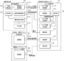
- the drawing is as follows. It is a block diagram which shows an example of the hardware configuration of the management system which concerns on 1st to 3rd Embodiment. It is a block diagram which shows an example of the functional structure of the management system which concerns on 1st to 3rd Embodiment. It is a schematic diagram which shows an example of the structure of the communication status information database which concerns on embodiment. It is a top view provided for the explanation of the communication record information included in the communication status information database which concerns on embodiment. It is a top view provided for the explanation of the unstable area information included in the communication situation information database which concerns on embodiment.
- the management system 90 according to the present embodiment manages the vehicle state of the autonomous driving vehicle by periodically communicating with the autonomous driving vehicle in which the autonomous driving support center automatically travels.
- the management system 90 according to the present embodiment includes a center-side device 10, a plurality of vehicle-side devices 20, a plurality of mobile terminals 40, and a plurality of mobile terminals 40, each of which can access the network 80.
- the operator device 50 and the like are included.
- Examples of the center-side device 10, the vehicle-side device 20, and the operator device 50 include general-purpose information processing devices such as personal computers and server computers.
- examples of the mobile terminal 40 include a portable terminal such as a smartphone, a tablet terminal, a PDA (Personal Digital Assistant, a mobile information terminal), a notebook type personal computer, and a terminal capable of wireless communication.
- the center-side device 10 is a device managed by the automatic driving support center that operates the management system 90.
- the center-side device 10 includes a CPU (Central Processing Unit) 11, a memory 12 as a temporary storage area, a non-volatile storage unit 13, an input unit 14 such as a keyboard and a mouse, a display unit 15 such as a liquid crystal display, and a medium reading / writing device (a medium reading / writing device). It includes an R / W) 16 and a communication interface (I / F) unit 18.
- the CPU 11, the memory 12, the storage unit 13, the input unit 14, the display unit 15, the medium reading / writing device 16, and the communication I / F unit 18 are connected to each other via the bus B1.
- the medium reading / writing device 16 reads out the information written on the recording medium 17 and writes the information on the recording medium 17.
- the storage unit 13 is realized by an HDD (Hard Disk Drive), an SSD (Solid State Drive), a flash memory, or the like.
- the center-side communication program 13A, the communication status information transmission program 13B, and the center-side communication interruption program 13C are stored in the storage unit 13 as a storage medium.
- the recording medium 17 on which the center-side communication program 13A, the communication status information transmission program 13B, and the center-side communication interruption program 13C are written reads and writes media.
- the CPU 11 reads the center side communication program 13A, the communication status information transmission program 13B, and the center side communication interruption program 13C from the storage unit 13 and deploys them in the memory 12, and deploys the center side communication program 13A, the communication status information transmission program 13B, and the center side.
- the processes of the communication interruption program 13C are sequentially executed.
- the communication status information database 13D is stored in the storage unit 13. The details of the communication status information database 13D will be described later.
- the vehicle-side device 20 is a device mounted on each of the autonomous driving vehicles that use the autonomous driving support service.
- the vehicle-side device 20 includes a CPU 21, a memory 22 as a temporary storage area, a non-volatile storage unit 23, an input unit 24 such as a keyboard and a mouse, a display unit 25 such as a liquid crystal display, a medium reading / writing device 26, a wireless communication unit 28, and the like.
- a position detection unit 29 is provided.
- the CPU 21, the memory 22, the storage unit 23, the input unit 24, the display unit 25, the medium reading / writing device 26, the wireless communication unit 28, and the position detection unit 29 are connected to each other via the bus B2.
- the medium reading / writing device 26 reads out the information written on the recording medium 27 and writes the information on the recording medium 27.
- the storage unit 23 is realized by an HDD, SSD, flash memory, or the like.
- the vehicle-side communication program 23A, the communication status information receiving program 23B, and the vehicle-side communication interruption program 23C are stored in the storage unit 23 as a storage medium.
- the recording medium 27 in which the vehicle-side communication program 23A, the communication status information reception program 23B, and the vehicle-side communication interruption program 23C are written is set in the medium read / write device 26, and the medium read / write device 26 is the vehicle-side communication program 23A from the recording medium 27.
- the CPU 21 reads the vehicle-side communication program 23A, the communication status information receiving program 23B, and the vehicle-side communication interruption program 23C from the storage unit 23 and deploys them in the memory 22, and deploys the vehicle-side communication program 23A, the communication status information receiving program 23B, and the vehicle-side communication program 23B.
- the processes included in the communication interruption program 23C are sequentially executed.
- the position detection unit 29 detects the position of the mounted autonomous vehicle, and in the present embodiment, the GPS (Global Positioning System) device is applied, but the present invention is not limited to this. Anything that can detect its own position can be applied as the position detection unit 29.
- GPS Global Positioning System
- the mobile terminal 40 is a device possessed by local staff deployed in various places within the management target area by the management system 90.
- the mobile terminal 40 includes a CPU 41, a memory 42 as a temporary storage area, a non-volatile storage unit 43, an input unit 44 such as a touch panel, a display unit 45 such as a liquid crystal display, and a wireless communication unit 48.
- the CPU 41, the memory 42, the storage unit 43, the input unit 44, the display unit 45, and the wireless communication unit 48 are connected to each other via the bus B4.
- the storage unit 43 is realized by an HDD, an SSD, a flash memory, or the like.
- the operator device 50 is a device operated by an operator who is a person who implements various services in the automatic driving support service.
- the operator device 50 includes a CPU 51, a memory 52 as a temporary storage area, a non-volatile storage unit 53, an input unit 54 such as a keyboard and a mouse, a display unit 55 such as a liquid crystal display, and a communication I / F unit 58.
- the CPU 51, the memory 52, the storage unit 53, the input unit 54, the display unit 55, and the communication I / F unit 58 are connected to each other via the bus B5.
- the storage unit 53 is realized by an HDD, an SSD, a flash memory, or the like.
- supporters Since the local staff and the operator both provide support for autonomous vehicles, these persons are collectively referred to as “supporters” below.
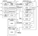
- the center-side device 10 includes a center-side receiving unit 11A, a management unit 11B, a center-side transmitting unit 11C, a center-side determining unit 11D, a requesting unit 11E, a communication unit 11F, and a setting unit. Includes 11G.
- the CPU 11 of the center side device 10 executes the center side communication program 13A, the communication status information transmission program 13B, and the center side communication interruption program 13C, the center side reception unit 11A, the management unit 11B, the center side transmission unit 11C, and the center side It functions as a determination unit 11D, a request unit 11E, a communication unit 11F, and a setting unit 11G.
- the vehicle-side device 20 includes a vehicle-side transmission unit 21A, a vehicle-side reception unit 21B, a vehicle-side determination unit 21C, and a stop unit 21D.
- the CPU 21 of the vehicle-side device 20 executes the vehicle-side communication program 23A, the communication status information reception program 23B, and the vehicle-side communication interruption program 23C, so that the vehicle-side transmission unit 21A, the vehicle-side reception unit 21B, the vehicle-side determination unit 21C, and the vehicle-side communication unit 21C are executed. It functions as a stop 21D.
- the vehicle side determination unit 21C automatically and the automatic driving support center at each position where the autonomous driving vehicle in the management target area by the management system 90 can travel. Based on the communication status information, which is information indicating the communication status with the driving vehicle, it is determined whether or not to continue the automatic driving.
- the center-side determination unit 11D contacts the supporter who provides support for the autonomous driving vehicle based on the communication status information when the communication with the autonomous driving vehicle is interrupted. To determine.
- communication between the center-side device 10 and the vehicle-side device 20 is always performed at predetermined period (for example, 0.5 seconds) intervals, and the predetermined period intervals are used.
- the state in which the communication in the above is interrupted continuously for a predetermined number of times (10 times as an example) or more is defined as the state in which the communication is interrupted.
- the time from transmission to reception is a predetermined period (for example, 3 seconds) or more.
- the state in which the delay occurs may be the state in which the communication is interrupted, and the state in which the received information is missing may be the state in which the communication is interrupted.
- the vehicle-side transmission unit 21A shows position information (in this embodiment, each information of latitude and longitude) indicating the traveling position of the self-driving vehicle provided by itself, and the time at that time.
- the probe information including the time information is transmitted to the center side device 10.
- the position information is acquired from the position detection unit 29.
- the time information is acquired from the clock unit built in the CPU 21.
- both the position information and the time information are included in the probe information, but the time information does not necessarily have to be included in the probe information.
- the center-side receiving unit 11A receives the probe information transmitted by the vehicle-side transmitting unit 21A, and the management unit 11B is included in the probe information received by the center-side receiving unit 11A.
- the location information is managed as communication record information in which communication is successful.
- the center-side transmission unit 11C transmits the communication record information managed by the management unit 11B to the vehicle-side device 20.
- the communication status information includes the communication record information. Therefore, the vehicle side determination unit 21C can determine whether or not to continue the automatic driving by using the communication record information, and whether the center side determination unit 11D also contacts the supporter by using the communication record information. You can decide whether or not.
- the communication status information indicates an area where the communication between the autonomous driving support center and the autonomous driving vehicle becomes unstable, which can be determined from the geographical information in the area managed by the management system 90. It is supposed to include unstable area information which is information. Therefore, the vehicle side determination unit 21C can determine whether or not to continue the automatic driving by using the unstable area information, and the center side determination unit 11D also contacts the supporter by using the unstable area information. You can decide whether or not to do it.
- the vehicle-side determination unit 21C determines the vehicle-side expected period, which is the period during which the interrupted communication is expected to be restored, based on the travel route and communication status information of the autonomous driving vehicle provided by the vehicle-side determination unit 21C. If the vehicle is out-licensed and the out-licensed vehicle-side expected period is within a predetermined period, it is determined that the automatic driving will be continued.
- a predetermined period a period derived from the past performance information is applied as a period in which no problem occurs even if the automatic driving is continued within the period. It is not limited to this.
- a form in which the operator or the like of the center side device 10 is made to set the above period in advance according to the cost that can be spent on the local staff in the automatic driving support service, the continuity required for the automatic driving support service, and the like. May be.
- the stop unit 21D is the case where the automatic traveling is continued in a state where the communication with the center side device 10 is interrupted, and even if the expected recovery point of the communication is reached. If communication is not restored, the automatic driving is stopped.
- the center-side determination unit 11D derives the center-side expected period, which is the period during which the interrupted communication is expected to be restored, based on the travel route and the communication status information of the autonomous driving vehicle in which the communication is interrupted. , If the derived center side expected period is within a predetermined period, it is decided not to contact the supporter. Further, the center-side determination unit 11D according to the present embodiment determines to contact the supporter when the communication with the autonomous driving vehicle is not restored even after the center-side expected period has elapsed.
- the communication unit 11F decides to contact the supporter after the center side determination unit 11D decides not to contact the supporter, the point where the supporter loses communication with the autonomous driving vehicle.
- the disruption-related information including both the routes on which the self-driving car is believed to have traveled during the disruption period.
- the interruption-related information for contacting the supporter includes both the point where the communication with the autonomous driving vehicle is interrupted and the route where the autonomous driving vehicle is considered to have traveled during the interruption period. Information is applied, but not limited to this.
- the interruption-related information to contact the supporter as a form of applying information including only one of the points where the communication with the autonomous vehicle is interrupted and the route where the autonomous vehicle is considered to have traveled during the interruption period. May be good.
- the requesting unit 11E when the communication with the autonomous driving vehicle whose communication is interrupted is restored, the requesting unit 11E according to the present embodiment provides the traveling state information indicating the traveling state of the autonomous driving vehicle during the period when the communication is interrupted. Request for the self-driving car. In response to this request, the autonomous driving vehicle transmits the traveling state information to the center side device 10.
- the setting unit 11G causes the supporter to confirm whether or not there is an abnormality in the traveling state indicated by the traveling state information obtained from the autonomous driving vehicle in response to the request by the requesting unit 11E, and the abnormality is found. If not, the information indicating the area where the communication between the autonomous driving support center and the autonomous driving vehicle becomes unstable in the communication interruption section, which is the section in which the autonomous driving vehicle traveled during the period when the communication was interrupted. Set to include in certain unstable area information.
- the mobile terminal 40 includes the processing unit 41A
- the operator device 50 includes the processing unit 51A.
- the CPU 41 of the mobile terminal 40 functions as the processing unit 41A by executing the program stored in the storage unit 43 in advance
- the CPU 51 of the operator device 50 executes the program stored in the storage unit 53 in advance to execute the processing unit 51A. Functions as.
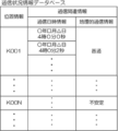
- the communication status information database 13D is a communication indicating the communication status at the position indicated by the corresponding location information for each position information indicating each position in the management target area by the management system 90.
- Related information is stored.
- the management target area by the management system 90 is viewed in a plane, and the management target area in the plan view is divided into a plurality of division areas having a predetermined shape and size in a matrix.
- the communication-related information (in the present embodiment, the communication date and time) corresponding to the position information indicating the position of each division area (in the present embodiment, the center position in the plan view of the division area) Information and each information of geographical communication information) are associated and stored.
- a square is applied as the shape of the division region, and 20 m ⁇ 20 m is applied as the size, but it goes without saying that the shape and size are not limited to these.
- the probe can communicate well with the autonomous driving vehicle at the position indicated by the position information included in the probe information received from the autonomous driving vehicle by the center-side receiving unit 11A.
- the time information included in the information is stored as communication date and time information in association with the corresponding location information. If the probe information does not include the time information, the time information indicating the time at that time is input from the clock unit built in the CPU 11 of the center side device 10 at the timing when the probe information is received by the center side device 10. You can get it and apply it.
- the combination of the location information of the communication status information database 13D and the communication date / time information corresponds to the above-mentioned communication record information.
- communication between the center side device 10 and the vehicle side device 20 becomes geographically unstable.
- Information indicating that the communication is geographically unstable is stored in the communication status information database 13D as geographical communication information in association with the position information indicating the position.
- the communication between the center side device 10 and the vehicle side device 20 is geographically stable in association with the position information indicating the position where the communication is not geographically unstable.
- Information indicating that the information is being sent is stored in the communication status information database 13D as geographical communication information.
- the information "unstable” is applied as the information indicating that the communication is geographically unstable, and the communication is geographically unstable.
- the information "ordinary” is applied as the information indicating that the information does not become, but it goes without saying that the information is not limited to this information.
- the communication between the center side device 10 and the vehicle side device 20 in the state where the autonomous driving vehicle is running is geographically stable. It is possible to grasp whether or not it is.
- the combination of the location information and the geographical communication information of the communication status information database 13D corresponds to the unstable area information described above.
- communication status information the information registered in the communication status information database 13D is collectively referred to as "communication status information”.
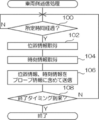
- the operation of the vehicle-side device 20 when executing the vehicle-side communication processing will be described as the operation of the vehicle-side device 20 according to the present embodiment.
- the CPU 21 of the vehicle-side device 20 mounted on any of the autonomous driving vehicles executes the vehicle-side communication program 23A
- the vehicle-side communication process shown in FIG. 6 is executed.
- the vehicle-side communication process shown in FIG. 6 is executed, for example, when automatic driving by an autonomous driving vehicle equipped with the vehicle-side device 20 is started.
- step 100 of FIG. 6 the vehicle-side transmission unit 21A waits until a predetermined time (0.5 seconds in the present embodiment) elapses, and in the next step 102, the vehicle-side transmission unit 21A of the own vehicle.
- the position information indicating the position is acquired from the position detection unit 29.
- the vehicle-side transmission unit 21A acquires time information indicating the time at that time
- the vehicle-side transmission unit 21A includes the acquired position information and time information in the probe information. Then, the information is transmitted to the center side device 10 via the wireless communication unit 28 and the network 80.
- the time information is acquired from the clock unit built in the CPU 21, but it goes without saying that the time information is not limited to this.
- the vehicle-side transmission unit 21A determines whether or not a predetermined end timing has arrived, and if a negative determination is made, the process returns to step 100.
- the vehicle side communication process is terminated.
- the timing at which the ignition off of the autonomous driving vehicle is detected is applied as the end timing, but the end timing is not limited to this.
- the end timing may be the timing at which the instruction information for instructing the end of the vehicle-side communication process is received from the center-side device 10 via the wireless communication unit 28.
- the operation of the center-side device 10 when executing the center-side communication processing will be described as the operation of the center-side device 10 according to the present embodiment.
- the center-side communication process shown in FIG. 7 is executed.
- the center-side communication process shown in FIG. 7 is executed when, for example, a predetermined time (for example, 4 o'clock) is set as the time when the service by the automatic driving support service is started.
- the center-side receiving unit 11A waits until probe information is received from any of the autonomous driving vehicles, and in the next step 502, the management unit 11B waits for a predetermined time (in this embodiment, the present embodiment). 2 seconds) Wait until it elapses.
- the management unit 11B stores the time information included in the received probe information in the corresponding storage area of the communication status information database 13D as the communication date and time information corresponding to the position information included in the probe information. (sign up. By registering probe information as communication status information at predetermined time intervals for each autonomous driving vehicle, the capacity of the communication status information database 13D can be reduced.
- the management unit 11B determines whether or not a predetermined end timing has arrived, and if a negative determination is made, the process returns to step 500, and when a positive determination is made, the center side. End the communication process.
- a predetermined time (1 o'clock as an example) is applied as the time when the service by the automatic driving support service is ended, but the end timing is limited to this. Absent.
- the end timing may be the timing at which the administrator of the center-side device 10 inputs the instruction information for instructing the end of the center-side communication process via the communication I / F unit 18.
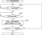
- the operation of the center-side device 10 when executing the communication status information transmission process will be described.
- the CPU 11 of the center-side device 10 executes the communication status information transmission program 13B
- the communication status information transmission process shown in FIG. 8 is executed.
- the communication status information transmission process shown in FIG. 8 is executed, for example, when a predetermined time (for example, 4 o'clock) is set as the time when the service by the automatic driving support service is started.
- step 600 of FIG. 8 the center-side transmission unit 11C waits until a predetermined timing for transmitting the communication status information to the autonomous driving vehicle arrives.
- a predetermined timing for transmitting the communication status information to the autonomous driving vehicle arrives.
- the timing of every predetermined time for example, 1 minute
- the timing is not limited to this.
- the center-side transmission unit 11C reads out all the communication status information from the communication status information database 13D.
- the center-side transmission unit 11C corresponds to the traveling position of the autonomous driving vehicle at the transmission destination from the read communication status information, and goes back from that time to a predetermined time (for example, 10 minutes) before.
- Information up to hereinafter referred to as "corresponding communication status information" is extracted.
- corresponding communication status information Information up to
- the center-side transmission unit 11C transmits the extracted corresponding communication status information to the autonomous driving vehicle via the communication I / F unit 18 and the network 80.
- the information corresponding to the traveling position of the destination autonomous vehicle the information about the inside of a predetermined range (for example, a radius of 1 km) around the traveling position of the corresponding autonomous vehicle is applied.
- a predetermined range for example, a radius of 1 km
- the corresponding communication status information all the communication status information registered in the communication status information database 13D may be applied, or the communication status information corresponding only to the traveling route of the destination autonomous vehicle may be applied. It may be a form or the like.
- the center-side transmission unit 11C determines whether or not a predetermined end timing has arrived, and if a negative determination is made, the process returns to step 600.
- the communication status information transmission process is terminated.
- the end timing a predetermined time (1 o'clock as an example) is applied as the time when the service by the automatic driving support service is ended, but the end timing is limited to this. Absent.
- the end timing may be the timing at which the administrator of the center-side device 10 inputs the instruction information for instructing the end of the communication status information transmission process via the communication I / F unit 18. ..
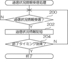
- the operation of the vehicle-side device 20 when executing the communication status information reception process will be described as the operation of the vehicle-side device 20 according to the present embodiment.
- the CPU 21 of the vehicle-side device 20 mounted on any of the autonomous driving vehicles executes the communication status information reception program 23B
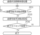
- the communication status information reception process shown in FIG. 9 is executed.
- the communication status information reception process shown in FIG. 9 is executed, for example, when the automatic driving by the autonomous driving vehicle equipped with the vehicle-side device 20 is started.
- step 200 of FIG. 9 the vehicle-side receiving unit 21B waits until the corresponding communication status information (hereinafter, simply referred to as “communication status information”) is received from the center-side device 10, and in the next step 202, the vehicle The side receiving unit 21B stores the received communication status information in a predetermined area of the storage unit 23.
- communication status information hereinafter, simply referred to as “communication status information”.
- the vehicle-side receiving unit 21B determines whether or not a predetermined end timing has arrived, and if a negative determination is made, the process returns to step 200.
- the communication status information reception process is terminated.
- the timing at which the ignition off of the autonomous driving vehicle is detected is applied as the end timing, but the end timing is not limited to this.
- the end timing may be the timing at which the instruction information for instructing the end of the communication status information reception process is received from the center-side device 10 via the wireless communication unit 28.
- the operation of the vehicle-side device 20 when the vehicle-side communication interruption process is executed will be described.
- the CPU 21 of the vehicle-side device 20 mounted on any of the autonomous driving vehicles executes the vehicle-side communication blackout program 23C
- the vehicle-side communication blackout process shown in FIG. 10 is executed.
- the vehicle-side communication interruption process shown in FIG. 10 is executed, for example, when automatic driving by an autonomous driving vehicle equipped with the vehicle-side device 20 is started.
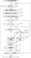
- step 300 of FIG. 10 the vehicle-side determination unit 21C determines whether or not the communication with the center-side device 10 is interrupted, and if a negative determination is made, the process proceeds to step 326 described later, while an affirmative determination is made. If it becomes, the process proceeds to step 302.
- step 302 the vehicle-side determination unit 21C reads out the communication status information stored by the above-mentioned communication status information reception process from the storage unit 23.
- step 304 the vehicle-side determination unit 21C uses the read communication status information to derive the expected communication restoration point, which is the position where the communication with the interrupted center-side device 10 is expected to be restored, as follows. ..
- the vehicle side determination unit 21C acquires the position information indicating the position at that time from the position detection unit 29, and the position indicated by the acquired position information is the position of the point where the communication with the center side device 10 is interrupted. (Hereinafter, it is referred to as "communication interruption start position").
- the vehicle-side determination unit 21C derives the position closer to the communication blackout start position among the positions satisfying each of the following conditions 1 and 2, as the expected communication recovery point.
- the method of deriving the expected communication recovery point is not limited to the above method.
- a position that meets any one of the above conditions 1 and 2 may be applied as a communication recovery expected point.
- the vehicle-side determination unit 21C uses the derived communication recovery prospective point to calculate the vehicle-side expected period Tc, which is the period during which communication with the center-side device 10 is expected to be restored, by the following equation (1). ) Is used for calculation.
- Ds in the formula (1) represents the mileage of the own vehicle from the communication interruption start position to the communication restoration expected point
- Sp represents the traveling speed of the own vehicle.
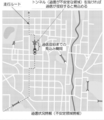
- the applied communication recovery expected point is obtained under the condition that meets the above condition 1, as shown in FIG. 11 as an example, the communication record information obtained by another autonomous vehicle or the like is used.
- the period during which the vehicle is expected to reach the obtained communication restoration expected point is calculated by the equation (1).
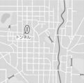
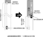
- the applied communication recovery expected point is obtained under the condition satisfying the above condition 2, as shown in FIG. 12 as an example, the communication such as a tunnel obtained by using the unstable area information can be obtained.
- the period during which the vehicle is expected to reach the expected communication restoration point is calculated by the equation (1).
- the vehicle-side determination unit 21C determines whether or not the calculated vehicle-side expected period Tc is equal to or less than a predetermined threshold value Th1, and if a negative determination is made, the process proceeds to step 324 described later. On the other hand, if a positive judgment is made, the process proceeds to step 310.
- step 310 the vehicle-side determination unit 21C sets the vehicle-side expected period Tc in a timer (in this embodiment, a timer built in the CPU 21) (not shown). According to the setting of the vehicle-side expected period Tc to this timer, the timer starts counting up to the vehicle-side estimated period Tc.
- a timer in this embodiment, a timer built in the CPU 21
- the vehicle side determination unit 21C starts storing (registering) the traveling state information indicating the traveling state of the own vehicle in the storage unit 23.
- the information indicating the traveling speed and the traveling position of the own vehicle is applied as the traveling state information, but the present invention is not limited to this, and the traveling state of the own vehicle such as the image of the in-vehicle camera and the sensing result is applied. Any information can be applied as long as it can be identified.
- step 314 the vehicle side determination unit 21C determines whether or not the communication with the center side device 10 has been restored, and if a positive determination is made, the process proceeds to step 316.
- step 316 when the vehicle-side transmitting unit 21A requests the traveling state information from the center-side device 10, the vehicle-side transmitting unit 21A reads the traveling state information stored up to this point from the storage unit 23, and reads the reading traveling state information from the center-side device. It is transmitted to 10 via the wireless communication unit 28 and the network 80.
- step 318 the vehicle side determination unit 21C stops the storage of the traveling state information started by the process of step 312, deletes the traveling state information from the storage unit 23, and then proceeds to step 326 described later.
- the traveling state information is transmitted from the autonomous driving vehicle to the center side device 10 in response to the request from the center side device 10, but the present invention is not limited to this.
- the traveling state information may be automatically transmitted to the center side device 10 when the interruption of communication with the center side device 10 is restored.
- step 314 the process proceeds to step 320, and the vehicle-side determination unit 21C acquires position information indicating the position at that time from the position detection unit 29. Then, the vehicle side determination unit 21C determines whether or not the position indicated by the acquired position information has reached the communication recovery expected point, and if a positive determination is made, the process proceeds to step 324 described later, while a negative determination is made. If it becomes, the process proceeds to step 322.
- step 322 the vehicle-side determination unit 21C determines whether or not the count-up of the timer has reached the set vehicle-side expected period Tc, and if a negative determination is made, the process returns to step 314, while making an affirmative determination. If it becomes, the process proceeds to step 324.
- step 324 the stop unit 21D controls the automatic traveling of the own vehicle to stop at the nearest road shoulder, and then proceeds to step 326.
- step 326 the vehicle side determination unit 21C determines whether or not the predetermined end timing has arrived, and if a negative determination is made, the process returns to step 300, while the vehicle side determines affirmatively. End the communication interruption process.
- the timing at which the ignition off of the autonomous driving vehicle is detected is applied as the end timing, but the end timing is not limited to this.
- the end timing may be the timing at which the instruction information for instructing the end of the vehicle-side communication interruption process is received from the center-side device 10 via the wireless communication unit 28.
- the center-side device 10 when the center-side communication interruption process is executed will be described.
- the CPU 11 of the center-side device 10 executes the center-side communication blackout program 13C
- the center-side communication blackout process shown in FIG. 13 is executed.
- the center-side communication interruption process shown in FIG. 13 is executed, for example, when a predetermined time (for example, 4 o'clock) is set as the time when the service by the automatic driving support service is started.
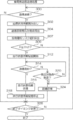
- step 700 of FIG. 13 the center-side determination unit 11D determines whether or not communication with any of the vehicle-side devices 20 is interrupted, and if a negative determination is made, the process proceeds to step 724, which will be described later. If the result is affirmative, the process proceeds to step 702. In the following, an autonomous vehicle whose communication has been interrupted will be referred to as a "processing target vehicle".
- step 702 the center-side determination unit 11D reads the communication status information from the communication status information database 13D.
- the center-side determination unit 11D uses the read communication status information to set the expected communication restoration point, which is the position where the communication with the vehicle-side device 20 of the vehicle to be processed is expected to be restored, as follows. Derived.
- the position indicated by the position information included in the probe information most recently received from the processing target vehicle by the above-mentioned center side communication processing is the position of the point where the communication with the processing target vehicle is interrupted. It is assumed that this is the communication interruption start position.
- the center-side determination unit 11D derives the position closer to the communication blackout start position among the positions satisfying each of the following conditions 3 and 4, as the expected communication recovery point.
- the method of deriving the expected communication recovery point is not limited to the above method.
- a position that meets any one of the above conditions 3 and 4 may be applied as a communication recovery expected point.
- the center-side determination unit 11D uses the derived communication restoration prospective point to calculate the center-side expected period Ts, which is the period during which communication with the vehicle to be processed is expected to be restored, by the following equation (2). Is calculated using.
- Ds in the formula (2) represents the mileage of the processing target vehicle from the communication interruption start position to the communication restoration expected point
- Sp represents the traveling speed of the processing target vehicle.
- the traveling speed Sp can be obtained from the amount of change in the traveling position per unit time indicated by the position information included in the probe information received by the center-side communication processing.
- the applied communication recovery expected point is obtained under the condition that meets the above condition 3, as shown in FIG. 11 as an example, the communication record information obtained by another autonomous vehicle or the like is used.
- the period during which the vehicle to be processed is expected to reach the obtained communication restoration expected point is calculated by the equation (2).
- the applied communication recovery expected point is obtained under the condition satisfying the above condition 4, as shown in FIG. 12 as an example, the communication such as a tunnel obtained by using the unstable area information can be obtained.
- the period during which the vehicle to be processed is expected to reach the communication restoration prospective point (the point marked with a star in FIG. 12 as an example), which is a position outside the unstable area, is calculated by the equation (2).
- the center-side determination unit 11D determines whether or not the calculated center-side expected period Ts is equal to or less than the predetermined threshold Th2, and if a negative determination is made, the process proceeds to step 722 described later. On the other hand, if a positive judgment is made, the process proceeds to step 710.
- the center-side determination unit 11D sets the center-side expected period Ts in a timer (in this embodiment, a timer built in the CPU 11) (not shown). According to the setting of the center-side expected period Ts to this timer, the timer starts counting up to the center-side expected period Ts.
- the center side determination unit 11D determines whether or not the communication with the vehicle to be processed has been restored, and if a positive determination is made, the process proceeds to step 714.
- the requesting unit 11E requests the processing target vehicle for the traveling state information indicating the traveling state of the processing target vehicle during the period when the communication is interrupted.
- the processing target vehicle transmits the traveling state information to the center side device 10 as described above.
- the setting unit 11G sets the running state information and the running state information so that the operator can confirm whether or not there is an abnormality in the running state indicated by the running state information received from the vehicle to be processed.
- the confirmation instruction information for instructing the confirmation is transmitted to the operator device 50 via the communication I / F unit 18 and the network 80.
- the processing unit 51A of the operator device 50 controls the display unit 55 so as to display the received running state information.
- the operator of the operator device 50 confirms whether or not there is a problem in the content of the traveling state information displayed on the display unit 55, and inputs the confirmation result information indicating the confirmation result via the input unit 54.
- the processing unit 51A transmits the input confirmation result information to the center side device 10 via the communication I / F unit 58 and the network 80.
- the setting unit 11G receives the confirmation result information from the operator device 50, and if the received confirmation result information is information indicating that there is no abnormality, the period during which the communication is interrupted.
- the section in which the vehicle to be processed travels in the unstable area information as an area where communication may become unstable, an update process that updates the communication status information database 13D is executed, and then an update process is executed, which will be described later. Step 724 is performed.
- step 712 determines whether or not the count-up of the timer has reached the set center-side expected period Ts, and makes a negative determination. If the result is, the process returns to step 712, while if the result is affirmative, the process proceeds to step 722.
- step 722 the communication unit 11F described above the information including each information of the point and time when the communication was interrupted, the route where the vehicle to be processed was considered to have traveled during the period when the communication was interrupted, and the expected communication recovery point. Derived as disruption-related information. Then, the communication unit 11F transmits the derived disruption-related information and the support instruction information for instructing the support of the processing target vehicle whose communication is interrupted to the mobile terminal 40 possessed by the local staff closest to the processing target vehicle. After transmitting via the F unit 18 and the network 80, the process proceeds to step 724.
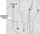
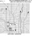
- the processing unit 41A of the mobile terminal 40 Upon receiving the interruption-related information and the support instruction information, the processing unit 41A of the mobile terminal 40 causes the display unit 45 to display the local staff presentation screen shown in FIG. 14 as an example.
- a point where communication is interrupted in FIG. 14, it is referred to as a “communication interruption point” and hereinafter referred to as a “communication interruption point”), and a communication recovery prospective point (“communication interruption point” in FIG. 14). It is described as “expected restoration point”, and hereafter, “expected restoration point”) is displayed.
- the vehicle to be processed traveled at the time when the communication was interrupted (indicated as "communication interruption occurrence time" in FIG. 14) and during the period when the communication was interrupted. The route is displayed.
- the local staff who referred to the local staff presentation screen shown in FIG. 14 searches the range from the communication interruption point to the expected restoration point, and the communication is not restored even after the expected period Ts on the center side elapses, that is, the vehicle to be processed, that is, the vehicle to be processed. It is possible to easily find the vehicle to be processed to be supported.
- the center-side determination unit 11D determines whether or not a predetermined end timing has arrived, and if a negative determination is made, the process returns to step 700, and when a positive determination is made, the center side determines. End the communication interruption process.
- the end timing a predetermined time (1 o'clock as an example) is applied as the time when the service by the automatic driving support service is ended, but the end timing is limited to this. Absent.
- the end timing may be the timing at which the administrator of the center-side device 10 inputs instruction information for instructing the end of the center-side communication interruption process via the communication I / F unit 18. ..
- the automatic driving vehicle within the management target area by the management system 90 is automatically driven at each position. Whether to continue automatic driving based on the communication status information, which is information indicating the communication status between the driving support center and the autonomous driving vehicle, and whether to contact the supporter who provides support for the autonomous driving vehicle I have decided whether or not. Therefore, it is possible to suppress a decrease in the continuity of the automatic driving support service and suppress an increase in the cost spent on the automatic driving support service.
- the vehicle side expected period is a period during which the interrupted communication is expected to be restored based on the travel route and communication status information of the autonomous driving vehicle provided by the vehicle side determination unit 21C.
- Tc is derived, and if the derived vehicle-side expected period Tc is within a predetermined period, it is determined that automatic driving will be continued. Therefore, by appropriately setting the predetermined period, it is possible to more appropriately suppress the decrease in the continuity of the automatic driving support service.
- the center-side expected period Ts which is the period during which the interrupted communication is expected to be restored based on the travel route and the communication status information of the autonomous driving vehicle in which the communication is interrupted by the center-side determination unit 11D. Is derived, and if the derived center-side expected period Ts is within a predetermined period, it is decided not to contact the supporter. Therefore, by appropriately setting the predetermined period, it is possible to more appropriately suppress an increase in the cost spent on the automatic driving support service.
- the center side determination unit 11D determines that if the communication with the autonomous driving vehicle is not restored even after the center side expected period Ts has elapsed, the supporter is contacted. Therefore, it is possible to suppress an increase in the cost spent on the automatic driving support service while maintaining the safety and security of the automatic driving support service.
- the vehicle-side determination unit 21C needs support on the way to the point where the interrupted communication is expected to be restored, based on the travel route and communication status information of the self-driving car provided by the vehicle side determination unit 21C. It is different from the first embodiment in that it is determined to continue the automatic driving when the degree of the driving is equal to or lower than a predetermined level.
- the above-mentioned route is a route without a pedestrian crossing, a route that is a pedestrian crossing road, and an autonomous vehicle gets on and off a bus, a taxi, or the like.
- the route does not have a passenger boarding / alighting point, and all the conditions are satisfied, it is determined that the degree of need for the above support is below the above level.
- the operation of the vehicle-side device 20 when the vehicle-side communication interruption process is executed as the operation of the vehicle-side device 20 according to the second embodiment will be described.
- the steps for executing the same process as the vehicle-side communication blackout process shown in FIG. 10 are given the same step numbers as those in FIG. 10, and the description thereof will be omitted.
- step 306 and step 308 are replaced with the processes of step 307 and step 309, respectively, and steps 310 and 322, respectively.
- the difference is that the process has been deleted.
- the vehicle-side determination unit 21C reads the route-related information from the storage unit 23, and uses the route-related information and the communication recovery prospective point derived by the process of step 304 to recover the communication.
- the automatic driving risk value R which indicates the degree to which support is required by the supporter on the way to the point, is calculated using the following equation (3).
- Cp in the formula (3) is substituted with "1" when there is a pedestrian crossing between the above-mentioned communication interruption start position and the communication recovery expected point (hereinafter, referred to as "risk target section"). Represents a variable to which "0" is assigned when there is no pedestrian crossing.
- Dp in the equation (3) represents a variable in which "1" is substituted when the risk target section is not a pedestrian-vehicle separated road, and "0" is substituted when the risk target section is a pedestrian-vehicle separated road.
- Ep in equation (3) when the autonomous vehicle is a vehicle that involves getting on and off a bus, taxi, etc., and there is a passenger boarding / alighting point in the risk target section, "1" is substituted and the boarding / alighting point is assigned. Represents a variable to which "0" is assigned when there is no. If the self-driving car is not a vehicle such as a bus or taxi that involves getting on and off, "0" is assigned to the variable Ep.
- the risk target section is a pedestrian-vehicle separation road
- the self-driving car is a vehicle that involves getting on and off a bus, taxi, or the like.
- "0" is calculated by the equation (3) as the automatic driving risk value R only when there is no boarding / alighting point for the passengers.
- the vehicle side determination unit 21C determines whether or not the calculated automatic driving risk value R is equal to or less than a predetermined threshold value Th3 (0 in this embodiment), and determines whether or not the calculated automatic driving risk value R is equal to or less than a predetermined threshold value Th3 (0 in this embodiment). If the result is, the process proceeds to step 324, while if the result is affirmative, the process proceeds to step 312.
- the vehicle side determination unit 21C reaches a point where the interrupted communication is expected to be restored based on the travel route and communication status information of the autonomous driving vehicle provided by the vehicle side determination unit 21C. If the degree to which support is required by the supporter (automatic driving risk value R) is less than or equal to a predetermined level (threshold value Th3), it is determined that automatic driving will be continued. Therefore, as compared with the case where the automatic driving risk value R is not used, it is possible to more appropriately suppress the decrease in the continuity of the automatic driving support service.
- a predetermined level Th3
- first condition a predetermined period
- second condition a predetermined level
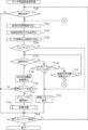
- the center-side determination unit 11D according to the third embodiment is different from the first embodiment in that it mainly uses the latest communication status information to determine whether or not to contact the supporter.
- step 710 is deleted, the process of step 715 is added, and the process of step 720 is the process of step 719 and step.
- the difference is that it replaces the processing of 721.
- step 715 of FIG. 17 the setting unit 11G determines whether or not it is predicted that the traveling state indicated by the traveling state information received from the autonomous driving vehicle is abnormal, and if a positive determination is made, the step On the other hand, if a negative determination is made, the process proceeds to step 716 without executing the processes of steps 716 and 718.
- whether or not the running state is predicted to be abnormal is determined by whether or not the absolute value of the acceleration calculated from the received running state information is equal to or greater than a predetermined threshold value, and the running. This is done by determining whether or not the traveling position indicated by the state information is unstable, but it goes without saying that it is not limited to these.
- step 719 the center-side determination unit 11D adds the center-side estimated period Ts calculated by the process of step 706 to the time when the communication with the autonomous vehicle is interrupted (hereinafter referred to as "communication recovery estimated time"). It is determined whether or not is before the current time, and if the determination is affirmative, the process proceeds to step 722, and if the determination is negative, the process proceeds to step 721.
- step 721 the center-side determination unit 11D determines whether or not the communication status information has been updated with respect to the one read in step 702, and if a positive determination is made, the process returns to step 702, while a negative determination is made. If so, the process returns to step 712.
- step 719 is negatively determined until the current time reaches the estimated communication recovery time
- the process proceeds to step 721 without executing the process of contacting the local staff (process of step 722).
- the processes of steps 712, 719, and 721 are repeatedly executed until the communication status information is updated. If the communication status information is updated while this iterative process is being executed, the process of step 721 returns to the process of step 702, and the center-side expected period Ts is set using the updated communication status information. It will be calculated again.
- step 719 becomes an affirmative judgment, and the local staff is immediately contacted.
- the communication device is out of order.
- the center side determination unit 11D recalculates the center side estimated period Ts every time the communication status information is updated. Therefore, it is possible to contact the local staff more quickly.
- the setting unit 11G confirms with the supporter whether or not there is an abnormality in the running state indicated by the running state information only when it is predicted that the running state of the vehicle to be processed is abnormal. I'm letting you. Therefore, the cost spent on the supporter can be further suppressed.
- the management system 90 according to the fourth embodiment and the management system 90 according to the first embodiment differ only in that the vehicle-side device 20 is provided with the external sensor 60.
- the outside world sensor 60 is a LiDAR that measures the distance to an obstacle and a camera that shoots the front direction of the autonomous driving vehicle, and the CPU 21 can acquire image information and distance measurement data obtained by the shooting. it can.
- the management system 90 according to the fourth embodiment communication with the automatic driving support center is interrupted in the vehicle side device 20 with respect to the management system 90 according to the first embodiment.
- a speed control unit 21E is newly provided to control the running speed to be lower than that before the period when the automatic running is continued during the period.
- the management system 90 according to the fourth embodiment is a transmission destination of the communication record information when the center side transmission unit 11C transmits the communication record information to the management system 90 according to the first embodiment.
- communicateable predicted point Based on the driving position and driving route of the autonomous driving vehicle, only the latest point information (hereinafter referred to as "communicable predicted point") that is predicted to be able to communicate at the point of the driving route is transmitted. It's different.
- the vehicle side determination unit 21C has a vehicle side expected period Tc within a predetermined period with respect to the management system 90 according to the first embodiment. The difference is that if it is determined that the vehicle can be safely driven according to the result of sensing by a predetermined sensor (in the present embodiment, the camera and LiDAR constituting the external sensor 60), it is determined to continue the automatic driving. ..
- the operation of the center-side device 10 when executing the communication status information transmission process will be described as the operation of the center-side device 10 according to the fourth embodiment.
- the steps for executing the same process as the communication status information transmission process shown in FIG. 8 are assigned the same step numbers as those in FIG. 8 and the description thereof will be omitted.
- the communication status information transmission process shown in FIG. 21 and the communication status information transmission process shown in FIG. 8 are different in that the processes of step 603 and step 605 are applied instead of the process of step 604.
- the center-side transmission unit 11C uses the communication status information read by the process of step 602 to derive the communication recovery prospect in the process of step 704 of the center-side communication interruption process shown in FIG. A communicable predicted point is derived by the same method as the point.
- the center-side transmission unit 11C transmits the derived information indicating the communicable predictive point to the destination autonomous vehicle via the communication I / F unit 18 and the network 80.
- the operation of the vehicle-side device 20 when executing the communication status information reception process will be described as the operation of the vehicle-side device 20 according to the fourth embodiment.
- the steps for executing the same process as the communication status information reception process shown in FIG. 9 are given the same step numbers as those in FIG. 9, and the description thereof will be omitted.
- the communication status information reception process shown in FIG. 22 and the communication status information reception process shown in FIG. 9 differ in that the processes of step 201 and step 203 are applied instead of the processes of step 200 and step 202, respectively. There is.
- the vehicle-side receiving unit 21B waits until the information indicating the communicable prediction point is received from the center-side device 10, and in the next step 203, the vehicle-side receiving unit 21B receives.
- the information indicating the communicable prediction point is stored in the predetermined area of the storage unit 23.
- the operation of the vehicle-side device 20 when executing the vehicle-side communication interruption process will be described.
- the same step number as that of FIG. 10 is assigned to the step of executing the same process as the vehicle-side communication blackout process shown in FIG. 10, and the description thereof will be omitted.
- step 303, step 305, and step 307 are applied instead of the processes of step 302, step 304, and step 306, respectively.
- step 304, and step 306 respectively.
- the point is different.
- the vehicle-side communication blackout process shown in FIG. 23 and the vehicle-side communication blackout process shown in FIG. 10 are different in that the processes of step 309 and step 315 are newly included.
- the vehicle side determination unit 21C reads out the information indicating the communicable predictive point stored by the communication status information reception process described above from the storage unit 23.
- the speed control unit 21E controls the traveling speed of the own vehicle so as to be lowered by a predetermined speed (for example, 10 km / h).
- the vehicle-side determination unit 21C sets the communicable predictive point indicated by the read information as the above-mentioned communication recovery expected point, and sets the traveling speed after being reduced by the process of step 305 as the traveling speed Sp.
- the vehicle-side expected period Tc is calculated using the equation (1).
- the center-side device 10 also calculates the center-side expected period Ts, assuming that the traveling speed of the vehicle to be processed is lower than that before the communication blackout.
- the vehicle side determination unit 21C determines whether or not there is an obstacle or the like that hinders the traveling of the own vehicle in front of the own vehicle based on the sensing result by the outside world sensor 60, thereby determining the outside world. It is determined whether or not there is a problem with the sensing result by the sensor 60, that is, whether or not the route to the expected communication recovery point can be safely passed by automatic driving, and if a positive determination is made, the process proceeds to step 310, while the process proceeds to step 310. If a negative determination is made, the process proceeds to step 324.
- step 315 the speed control unit 21E controls to return the traveling speed of the own vehicle, which has been reduced by the process of step 305, to the original speed.
- the center-side transmission unit 11C transmits the communication record information, it is based on the travel position and the travel route of the autonomous driving vehicle to which the communication record information is transmitted. , Only the latest point information that is predicted to be able to communicate at the point of the driving route is transmitted. Therefore, the information related to the communication record can be transmitted more efficiently than the case where the communication record information itself is transmitted.
- the vehicle-side determination unit 21C enables the vehicle-side expected period Tc to be within a predetermined period and to be able to drive safely according to the result of sensing by the predetermined sensor. If it is judged, it is decided to continue automatic driving. Therefore, it is possible to continue automatic driving more appropriately.
- the traveling speed is increased as compared with that before the period. It is controlled to decrease. Therefore, the safety of automatic driving can be improved.
- the management unit 11B, the center side determination unit 11D, the request unit 11E, the communication unit 11F, and the setting unit 11G are provided in the center side device 10, and the vehicle side determination unit 21C, the stop unit 21D, and the speed control unit are provided.
- the 21E is provided in the vehicle side device 20 has been described, but the present invention is not limited to this.
- each of these parts may be provided in either the center-side device 10 or the vehicle-side device 20 within a range in which the corresponding function can be executed.
- the communication interruption section set as unstable area information by the setting unit 11G by the process of step 718 of the center side communication interruption processing is set by the setting unit.
- the communication interruption section When communication with another autonomous vehicle traveling in the communication interruption section is not interrupted by 11G, it may be set to be excluded from the unstable area information. Thereby, the occurrence of unnecessary determination can be reduced.
- each of the mathematical formulas (1) to (3) according to each of the above embodiments is an example, and various modifications can be added to each mathematical formula.
- equation (3) the values of the variables Cp, Dp, and Ep are added, but by multiplying the values of these variables, the automatic driving risk value R can be obtained. It can also be in the form of calculation.
- the configuration of each device according to each of the above embodiments is an example, and the configuration of each device can be changed within a range that does not deviate from the gist of the present disclosure.
- the center-side device 10 and the vehicle-side device 20 have an input unit and a display unit, but each device may not have these parts.
- the center side receiving unit 11A, the management unit 11B, the center side transmitting unit 11C, the center side determining unit 11D, the requesting unit 11E, the contact unit 11F, the setting unit 11G, and the vehicle side transmitting unit 21A includes various processors shown below. Can be used. As described above, the various processors include a CPU, which is a general-purpose processor that executes software (program) and functions as a processing unit, and a circuit configuration after manufacturing an FPGA (Field-Programmable Gate Array) or the like.
- a CPU which is a general-purpose processor that executes software (program) and functions as a processing unit
- FPGA Field-Programmable Gate Array
- a dedicated electric circuit that is a processor having a circuit configuration specially designed to execute a specific process such as a programmable logic device (PLD), an ASIC (Application Specific Integrated Circuit), which is a processor that can change the CPU. Etc. are included.
- PLD programmable logic device
- ASIC Application Specific Integrated Circuit
- the processing unit may be composed of one of these various processors, or a combination of two or more processors of the same type or different types (for example, a combination of a plurality of FPGAs or a combination of a CPU and an FPGA). It may be composed of. Further, the processing unit may be configured by one processor.
- one processor is configured by a combination of one or more CPUs and software, and this processor There is a form that functions as a processing unit.
- SoC System On Chip
- a processor that realizes the functions of the entire system including the processing unit with one IC (Integrated Circuit) chip is used.
- the processing unit is configured by using one or more of the above-mentioned various processors as a hardware structure.
- an electric circuit in which circuit elements such as semiconductor elements are combined can be used.
Landscapes
- Engineering & Computer Science (AREA)
- Physics & Mathematics (AREA)
- General Physics & Mathematics (AREA)
- Automation & Control Theory (AREA)
- Signal Processing (AREA)
- Computer Networks & Wireless Communication (AREA)
- Mechanical Engineering (AREA)
- Transportation (AREA)
- Human Computer Interaction (AREA)
- Remote Sensing (AREA)
- Analytical Chemistry (AREA)
- Chemical & Material Sciences (AREA)
- Life Sciences & Earth Sciences (AREA)
- Radar, Positioning & Navigation (AREA)
- Atmospheric Sciences (AREA)
- Aviation & Aerospace Engineering (AREA)
- Traffic Control Systems (AREA)
- Mobile Radio Communication Systems (AREA)
Abstract
管理システムは、自動運転支援センタが自動走行する自動運転車と定期的に通信することで自動運転車の車両状態を管理する管理システムであって、自動運転車に設けられ、自動運転支援センタとの通信が途絶した場合に、管理システムによる管理対象領域内の自動運転車が走行可能な各位置における自動運転支援センタと自動運転車との間の通信の状況を示す情報である通信状況情報に基づいて、自動走行を継続するか否かを決定する車両側決定部(21C)を備えた車両側装置(20)と、自動運転支援センタに設けられ、自動運転車との通信が途絶した場合に、通信状況情報に基づいて、自動運転車に対する支援を行う支援者に連絡するか否かを決定するセンタ側決定部(11D)を備えたセンタ側装置(10)と、を含む。
Description
本出願は、2019年10月29日に出願された日本出願番号2019-196062号に基づくもので、ここにその記載内容を援用する。
本開示は、管理システム、管理方法、及び管理プログラムに関する。
従来、自動運転車と、ネットワークを介して当該自動運転車と通信を行う遠隔監視センタと、から構成される遠隔監視システムが提案されている(特許文献1参照)。
この遠隔監視システムでは、自動運転車により、遠隔監視センタとの間の通信が途絶した場合に当該自動運転車を自動停止させ、かつ、カメラ映像を遠隔監視センタに送信し、当該自動停止の後、遠隔監視センタから発進信号を受信した場合、当該自動運転車の走行を再開させる制御を行う。
また、この遠隔監視システムでは、遠隔監視センタにより、上記自動運転車が自動停止した場合、受信したカメラ映像に基づいて当該自動運転車の走行を再開させてよいかどうか判断し、当該自動運転車の走行を再開させてよいと判断した場合には、当該自動運転車に発進信号を送信する。
発明者の詳細な検討の結果、上記特許文献1に開示された技術では、自動運転車と遠隔監視センタとの間の通信が途絶する度に自動運転車の運行が停止されるため、自動運転支援サービスの継続性が損なわれる、という課題が見出された。
また、発明者は、上記特許文献1に開示された技術では、自動運転車と遠隔監視センタとの間の通信が途絶する度に自動運転支援サービスにおいて自動運転車を支援するオペレータや現地スタッフ等の支援者に連絡されるため、当該サービスに費やすコストの上昇を招く、という課題も見出した。
本開示は、自動運転支援サービスの継続性の低下を抑制し、かつ、自動運転支援サービスに費やすコストの上昇を抑制することができるようにすることを目的とする。
本開示に係る管理システムは、自動運転支援センタが自動走行する自動運転車と定期的に通信することで前記自動運転車の車両状態を管理する管理システムであって、前記自動運転車に設けられ、前記自動運転支援センタとの通信が途絶した場合に、前記管理システムによる管理対象領域内の前記自動運転車が走行可能な各位置における前記自動運転支援センタと前記自動運転車との間の通信の状況を示す情報である通信状況情報に基づいて、自動走行を継続するか否かを決定する車両側決定部を備えた車両側装置と、前記自動運転支援センタに設けられ、前記自動運転車との通信が途絶した場合に、前記通信状況情報に基づいて、前記自動運転車に対する支援を行う支援者に連絡するか否かを決定するセンタ側決定部を備えたセンタ側装置と、を含んで構成することができる。
また、本開示に係る管理方法は、自動運転支援センタが自動走行する自動運転車と定期的に通信することで前記自動運転車の車両状態を管理する管理システムで用いられる管理方法であって、前記自動運転支援センタと前記自動運転車との通信が途絶した場合に、前記管理システムによる管理対象領域内の前記自動運転車が走行可能な各位置における前記自動運転支援センタと前記自動運転車との間の通信の状況を示す情報である通信状況情報に基づいて、自動走行を継続するか否か、及び、前記自動運転車に対する支援を行う支援者に連絡するか否かを決定する方法である。
また、本開示に係る管理プログラムは、自動運転支援センタが自動走行する自動運転車と定期的に通信することで前記自動運転車の車両状態を管理する管理システムで用いられる管理プログラムであって、前記自動運転支援センタと前記自動運転車との通信が途絶した場合に、前記管理システムによる管理対象領域内の前記自動運転車が走行可能な各位置における前記自動運転支援センタと前記自動運転車との間の通信の状況を示す情報である通信状況情報に基づいて、自動走行を継続するか否か、及び、前記自動運転車に対する支援を行う支援者に連絡するか否かを決定する、処理をコンピュータに実行させるためのプログラムである。
本開示に係る管理システム、管理方法、及び管理プログラムによれば、自動運転支援サービスの継続性の低下を抑制し、かつ、自動運転支援サービスに費やすコストの上昇を抑制することができる。
本開示についての上記目的およびその他の目的、特徴や利点は、添付の図面を参照しながら下記の詳細な記述により、より明確になる。その図面は、下記の通りである。
第1~第3実施形態に係る管理システムのハードウェア構成の一例を示すブロック図である。
第1~第3実施形態に係る管理システムの機能的な構成の一例を示すブロック図である。
実施形態に係る通信状況情報データベースの構成の一例を示す模式図である。
実施形態に係る通信状況情報データベースに含まれる通信実績情報の説明に供する平面図である。
実施形態に係る通信状況情報データベースに含まれる不安定領域情報の説明に供する平面図である。
実施形態に係る車両側通信処理の一例を示すフローチャートである。
実施形態に係るセンタ側通信処理の一例を示すフローチャートである。
第1~第3実施形態に係る通信状況情報送信処理の一例を示すフローチャートである。
第1~第3実施形態に係る通信状況情報受信処理の一例を示すフローチャートである。
第1、第3実施形態に係る車両側通信途絶処理の一例を示すフローチャートである。
実施形態に係る車両側及びセンタ側通信途絶処理の説明に供する平面図である。
実施形態に係る車両側及びセンタ側通信途絶処理の説明に供する平面図である。
第1、第2、第4実施形態に係るセンタ側通信途絶処理の一例を示すフローチャートである。
実施形態に係る現地スタッフ提示画面の一例を示す正面図である。
第2実施形態に係る車両側通信途絶処理の一例を示すフローチャートである。
第2実施形態に係る車両側通信途絶処理の説明に供する平面図である。
第3実施形態に係るセンタ側通信途絶処理の一例を示すフローチャートである。
第3実施形態に係るセンタ側通信途絶処理の説明に供する平面図である。
第4実施形態に係る管理システムのハードウェア構成の一例を示すブロック図である。
第4実施形態に係る管理システムの機能的な構成の一例を示すブロック図である。
第4実施形態に係る通信状況情報送信処理の一例を示すフローチャートである。
第4実施形態に係る通信状況情報受信処理の一例を示すフローチャートである。
第4実施形態に係る車両側通信途絶処理の一例を示すフローチャートである。
以下、図面を参照して、本開示の技術を実施するための形態例を詳細に説明する。
[第1実施形態]
まず、図1及び図2を参照して、本実施形態に係る管理システム90の構成を説明する。本実施形態に係る管理システム90は、自動運転支援センタが自動走行する自動運転車と定期的に通信することで当該自動運転車の車両状態を管理するものである。本実施形態に係る管理システム90は、一例として図1に示すように、ネットワーク80に各々アクセス可能とされた、センタ側装置10と、複数の車両側装置20と、複数の携帯端末40と、オペレータ装置50と、を含む。なお、センタ側装置10、車両側装置20及びオペレータ装置50の例としては、パーソナルコンピュータ及びサーバコンピュータ等の汎用の情報処理装置が挙げられる。また、携帯端末40の例としては、スマートフォン、タブレット端末、PDA(Personal Digital Assistant、携帯情報端末)、ノートブック型パーソナルコンピュータ等の携帯型で、かつ、無線通信可能な端末が挙げられる。
まず、図1及び図2を参照して、本実施形態に係る管理システム90の構成を説明する。本実施形態に係る管理システム90は、自動運転支援センタが自動走行する自動運転車と定期的に通信することで当該自動運転車の車両状態を管理するものである。本実施形態に係る管理システム90は、一例として図1に示すように、ネットワーク80に各々アクセス可能とされた、センタ側装置10と、複数の車両側装置20と、複数の携帯端末40と、オペレータ装置50と、を含む。なお、センタ側装置10、車両側装置20及びオペレータ装置50の例としては、パーソナルコンピュータ及びサーバコンピュータ等の汎用の情報処理装置が挙げられる。また、携帯端末40の例としては、スマートフォン、タブレット端末、PDA(Personal Digital Assistant、携帯情報端末)、ノートブック型パーソナルコンピュータ等の携帯型で、かつ、無線通信可能な端末が挙げられる。
本実施形態に係るセンタ側装置10は、管理システム90を運営する自動運転支援センタが管理する装置である。センタ側装置10は、CPU(Central Processing Unit)11、一時記憶領域としてのメモリ12、不揮発性の記憶部13、キーボードとマウス等の入力部14、液晶ディスプレイ等の表示部15、媒体読み書き装置(R/W)16及び通信インタフェース(I/F)部18を備えている。CPU11、メモリ12、記憶部13、入力部14、表示部15、媒体読み書き装置16及び通信I/F部18はバスB1を介して互いに接続されている。媒体読み書き装置16は、記録媒体17に書き込まれている情報の読み出し及び記録媒体17への情報の書き込みを行う。
記憶部13はHDD(Hard Disk Drive)、SSD(Solid State Drive)、フラッシュメモリ等によって実現される。記憶媒体としての記憶部13には、センタ側通信プログラム13A、通信状況情報送信プログラム13B及びセンタ側通信途絶プログラム13Cが記憶されている。センタ側通信プログラム13A、通信状況情報送信プログラム13B及びセンタ側通信途絶プログラム13Cは、センタ側通信プログラム13A、通信状況情報送信プログラム13B及びセンタ側通信途絶プログラム13Cが書き込まれた記録媒体17が媒体読み書き装置16にセットされ、媒体読み書き装置16が記録媒体17からのセンタ側通信プログラム13A、通信状況情報送信プログラム13B及びセンタ側通信途絶プログラム13Cの読み出しを行うことで、記憶部13へ記憶される。CPU11は、センタ側通信プログラム13A、通信状況情報送信プログラム13B及びセンタ側通信途絶プログラム13Cを記憶部13から読み出してメモリ12に展開し、センタ側通信プログラム13A、通信状況情報送信プログラム13B及びセンタ側通信途絶プログラム13Cが各々有するプロセスを順次実行する。
また、記憶部13には、通信状況情報データベース13Dが記憶される。通信状況情報データベース13Dについては、詳細を後述する。
一方、本実施形態に係る車両側装置20は、自動運転支援サービスを利用する自動運転車の各々に搭載されている装置である。車両側装置20は、CPU21、一時記憶領域としてのメモリ22、不揮発性の記憶部23、キーボードとマウス等の入力部24、液晶ディスプレイ等の表示部25、媒体読み書き装置26、無線通信部28及び位置検出部29を備えている。CPU21、メモリ22、記憶部23、入力部24、表示部25、媒体読み書き装置26、無線通信部28及び位置検出部29はバスB2を介して互いに接続されている。媒体読み書き装置26は、記録媒体27に書き込まれている情報の読み出し及び記録媒体27への情報の書き込みを行う。
記憶部23はHDD、SSD、フラッシュメモリ等によって実現される。記憶媒体としての記憶部23には、車両側通信プログラム23A、通信状況情報受信プログラム23B及び車両側通信途絶プログラム23Cが記憶されている。車両側通信プログラム23A、通信状況情報受信プログラム23B及び車両側通信途絶プログラム23Cが書き込まれた記録媒体27が媒体読み書き装置26にセットされ、媒体読み書き装置26が記録媒体27からの車両側通信プログラム23A、通信状況情報受信プログラム23B及び車両側通信途絶プログラム23Cの読み出しを行うことで、記憶部23へ記憶される。CPU21は、車両側通信プログラム23A、通信状況情報受信プログラム23B及び車両側通信途絶プログラム23Cを記憶部23から読み出してメモリ22に展開し、車両側通信プログラム23A、通信状況情報受信プログラム23B及び車両側通信途絶プログラム23Cが有するプロセスを順次実行する。
位置検出部29は、搭載している自動運転車の位置を検出するものであり、本実施形態では、GPS(Global Positioning System)装置を適用しているが、これに限るものではない。自身の位置を検出することができるものであれば、如何なるものも位置検出部29として適用することができる。
一方、本実施形態に係る携帯端末40は、管理システム90による管理対象領域内の各地に配備された現地スタッフが所持する装置である。携帯端末40は、CPU41、一時記憶領域としてのメモリ42、不揮発性の記憶部43、タッチパネル等の入力部44、液晶ディスプレイ等の表示部45及び無線通信部48を備えている。CPU41、メモリ42、記憶部43、入力部44、表示部45及び無線通信部48はバスB4を介して互いに接続されている。記憶部43は、HDD、SSD、フラッシュメモリ等によって実現される。
更に、本実施形態に係るオペレータ装置50は、自動運転支援サービスにおける各種サービスを実施する要員であるオペレータが操作する装置である。オペレータ装置50は、CPU51、一時記憶領域としてのメモリ52、不揮発性の記憶部53、キーボードとマウス等の入力部54、液晶ディスプレイ等の表示部55及び通信I/F部58を備えている。CPU51、メモリ52、記憶部53、入力部54、表示部55及び通信I/F部58はバスB5を介して互いに接続されている。記憶部53はHDD、SSD、フラッシュメモリ等によって実現される。
なお、上記現地スタッフ及び上記オペレータは、共に自動運転車に対する支援を行う者であるため、以下では、これらの人を「支援者」と総称する。
次に、図2を参照して、本実施形態に係る管理システム90に含まれる各装置の機能的な構成について説明する。
図2に示すように、本実施形態に係るセンタ側装置10は、センタ側受信部11A、管理部11B、センタ側送信部11C、センタ側決定部11D、要求部11E、連絡部11F及び設定部11Gを含む。センタ側装置10のCPU11がセンタ側通信プログラム13A、通信状況情報送信プログラム13B及びセンタ側通信途絶プログラム13Cを実行することで、センタ側受信部11A、管理部11B、センタ側送信部11C、センタ側決定部11D、要求部11E、連絡部11F及び設定部11Gとして機能する。
一方、本実施形態に係る車両側装置20は、車両側送信部21A、車両側受信部21B、車両側決定部21C及び停止部21Dを含む。車両側装置20のCPU21が車両側通信プログラム23A、通信状況情報受信プログラム23B及び車両側通信途絶プログラム23Cを実行することで、車両側送信部21A、車両側受信部21B、車両側決定部21C及び停止部21Dとして機能する。
本実施形態に係る車両側決定部21Cは、自動運転支援センタとの通信が途絶した場合に、管理システム90による管理対象領域内の自動運転車が走行可能な各位置における自動運転支援センタと自動運転車との間の通信の状況を示す情報である通信状況情報に基づいて、自動走行を継続するか否かを決定する。
これに対し、本実施形態に係るセンタ側決定部11Dは、自動運転車との通信が途絶した場合に、通信状況情報に基づいて、自動運転車に対する支援を行う支援者に連絡するか否かを決定する。
なお、本実施形態に係る自動運転支援サービスでは、センタ側装置10と車両側装置20との間の通信を所定期間(一例として、0.5秒)間隔で常時行っており、この所定期間間隔での通信が所定回数(一例として、10回)以上連続して途切れた状態を、通信が途絶した状態としている。但し、この形態に限らず、センタ側装置10と車両側装置20との間の通信は継続的に行われているものの、送信から受信までの時間に所定期間(一例として、3秒)以上の遅延が生じている状態を通信が途絶した状態としてもよいし、受信した情報に欠落が生じている状態を通信が途絶した状態としてもよい。
一方、本実施形態に係る車両側送信部21Aは、自身が設けられた自動運転車の走行位置を示す位置情報(本実施形態では、緯度及び経度の各情報)と、その時点の時刻を示す時刻情報とを含むプローブ情報をセンタ側装置10に送信する。なお、本実施形態では、上記位置情報を位置検出部29から取得している。また、本実施形態では、上記時刻情報を、CPU21に内蔵された時計部から取得している。このように、本実施形態では、プローブ情報に位置情報及び時刻情報の双方を含めているが、時刻情報については必ずしもプローブ情報に含める必要はない。
これに対し、本実施形態に係るセンタ側受信部11Aは、車両側送信部21Aによって送信されたプローブ情報を受信し、管理部11Bは、センタ側受信部11Aによって受信されたプローブ情報に含まれる位置情報を、通信が成功した通信実績情報として管理する。そして、本実施形態に係るセンタ側送信部11Cは、管理部11Bによって管理されている通信実績情報を、車両側装置20に送信する。
本実施形態では、上記通信状況情報が、上記通信実績情報を含むものとしている。従って、車両側決定部21Cは、通信実績情報を用いて自動走行を継続するか否かを決定することができ、センタ側決定部11Dもまた、通信実績情報を用いて支援者に連絡するか否かを決定することができる。
また、本実施形態では、通信状況情報が、管理システム90による管理対象領域内における地理的情報から判断可能な、自動運転支援センタと自動運転車との間の通信が不安定となる領域を示す情報である不安定領域情報を含むものとしている。従って、車両側決定部21Cは、不安定領域情報も用いて自動走行を継続するか否かを決定することができ、センタ側決定部11Dもまた、不安定領域情報も用いて支援者に連絡するか否かを決定することができる。
ここで、本実施形態に係る車両側決定部21Cは、自身が設けられた自動運転車の走行ルート及び通信状況情報に基づいて、途絶した通信が復旧すると見込まれる期間である車両側見込み期間を導出し、導出した車両側見込み期間が予め定められた期間以内である場合、自動走行を継続すると決定する。なお、本実施形態では、上記予め定められた期間として、当該期間以内であれば自動走行を継続しても問題が生じない期間として、過去の実績情報から導出した期間を適用しているが、これに限るものではない。例えば、本自動運転支援サービスにおいて現地スタッフに費やすことのできるコストや、本自動運転支援サービスに求められる継続性等に応じて、センタ側装置10の操作者等に上記期間を予め設定させる形態等としてもよい。
更に、本実施形態に係る停止部21Dは、センタ側装置10との間の通信が途絶した状態で自動走行を継続している場合で、かつ、当該通信の復旧見込み地点に到達しても当該通信が復旧しない場合、当該自動走行を停止させる。
一方、本実施形態に係るセンタ側決定部11Dは、通信が途絶した自動運転車の走行ルート及び通信状況情報に基づいて、途絶した通信が復旧すると見込まれる期間であるセンタ側見込み期間を導出し、導出したセンタ側見込み期間が予め定められた期間以内である場合、支援者に連絡しないと決定する。また、本実施形態に係るセンタ側決定部11Dは、センタ側見込み期間が経過しても自動運転車との通信が復旧しない場合、支援者に連絡すると決定する。
そして、本実施形態に係る連絡部11Fは、センタ側決定部11Dが支援者に連絡しないと決定した後に支援者に連絡すると決定した場合、当該支援者に自動運転車との通信が途絶した地点、及び途絶している期間に自動運転車が走行したと考えられる経路の双方を含む途絶関連情報を連絡する。このように、本実施形態では、支援者に連絡する途絶関連情報として、自動運転車との通信が途絶した地点及び途絶している期間に自動運転車が走行したと考えられる経路の双方を含む情報を適用しているが、これに限らない。支援者に連絡する途絶関連情報として、自動運転車との通信が途絶した地点及び途絶している期間に自動運転車が走行したと考えられる経路の何れか一方のみを含む情報を適用する形態としてもよい。
一方、本実施形態に係る要求部11Eは、通信が途絶した自動運転車との通信が復旧した場合、当該通信が途絶していた期間中の当該自動運転車の走行状態を示す走行状態情報を当該自動運転車に要求する。この要求に応じて、自動運転車は、走行状態情報をセンタ側装置10に送信する。
また、本実施形態に係る設定部11Gは、要求部11Eによる要求に応じて自動運転車から得られた走行状態情報が示す走行状態に異常があるか否かを支援者に確認させ、異常がない場合、通信が途絶していた期間中に当該自動運転車が走行した区間である通信途絶区間を、自動運転支援センタと自動運転車との間の通信が不安定となる領域を示す情報である不安定領域情報に含める設定を行う。
一方、本実施形態に係る携帯端末40は処理部41Aを含み、オペレータ装置50は処理部51Aを含む。携帯端末40のCPU41が記憶部43に予め記憶されたプログラムを実行することで処理部41Aとして機能し、オペレータ装置50のCPU51が記憶部53に予め記憶されたプログラムを実行することで処理部51Aとして機能する。
次に、図3を参照して、本実施形態に係る通信状況情報データベース13Dについて説明する。
図3に示すように、本実施形態に係る通信状況情報データベース13Dは、管理システム90による管理対象領域内の各位置を示す位置情報毎に、対応する位置情報が示す位置における通信状況を示す通信関連情報が記憶される。本実施形態に係る管理システム90では、管理システム90による管理対象領域を平面視し、当該平面視した管理対象領域を予め定められた形状及びサイズの複数の区分領域にマトリクス状に区分する。そして、本実施形態に係る管理システム90では、各区分領域の位置(本実施形態では、区分領域の平面視中心位置)を示す位置情報に、対応する通信関連情報(本実施形態では、通信日時情報及び地理的通信情報の各情報)を関連付けて記憶する。なお、本実施形態では、上記区分領域の形状として正方形を適用し、上記サイズとして20m×20mを適用しているが、これらの形状及びサイズには限定されないことは言うまでもない。
本実施形態に係る管理システム90では、センタ側受信部11Aによって自動運転車から受信されたプローブ情報に含まれる位置情報が示す位置においては自動運転車との通信が良好に行えるものとして、当該プローブ情報に含まれる時刻情報を通信日時情報として、対応する位置情報に関連付けて記憶する。なお、プローブ情報に時刻情報が含まれない場合には、センタ側装置10においてプローブ情報を受信したタイミングでセンタ側装置10のCPU11に内蔵された時計部から、その時点の時刻を示す時刻情報を取得して適用すればよい。
従って、この通信日時情報と位置情報との組み合わせを参照することにより、一例として図4に示すように、自動運転車が走行している状態における、センタ側装置10と車両側装置20との間の通信実績を把握することができる。通信状況情報データベース13Dの位置情報と通信日時情報との組み合わせが上述した通信実績情報に相当する。
また、本実施形態に係る管理システム90では、一例として図5に示すように、トンネルや高架下等といった、センタ側装置10と車両側装置20との間の通信が地理的に不安定となる位置を示す位置情報に関連付けて、通信が地理的に不安定であることを示す情報を地理的通信情報として通信状況情報データベース13Dに記憶する。また、本実施形態に係る管理システム90では、センタ側装置10と車両側装置20との間の通信が地理的に不安定とはならない位置を示す位置情報に関連付けて、通信が地理的に安定していることを示す情報を地理的通信情報として通信状況情報データベース13Dに記憶する。なお、本実施形態では、一例として図3に示すように、上記通信が地理的に不安定であることを示す情報として「不安定」との情報を適用し、上記通信が地理的に不安定とならないことを示す情報として「普通」との情報を適用しているが、これらの情報に限るものではないことは言うまでもない。
従って、この地理的通信情報と位置情報との組み合わせを参照することにより、自動運転車が走行している状態における、センタ側装置10と車両側装置20との間の通信が地理的に安定しているか否かを把握することができる。通信状況情報データベース13Dの位置情報と地理的通信情報との組み合わせが上述した不安定領域情報に相当する。
以下では、通信状況情報データベース13Dに登録されている情報を、「通信状況情報」と総称する。
次に、図6~図14を参照して、本実施形態に係る管理システム90の作用を説明する。なお、錯綜を回避するために、ここでは、通信状況情報データベース13Dにおける位置情報及び地理的通信情報が予め登録されている場合について説明する。
まず、図6を参照して、本実施形態に係る車両側装置20の作用として、車両側通信処理を実行する場合の車両側装置20の作用を説明する。何れかの自動運転車に搭載された車両側装置20のCPU21が車両側通信プログラム23Aを実行することによって、図6に示す車両側通信処理が実行される。図6に示す車両側通信処理は、例えば、車両側装置20が搭載された自動運転車による自動走行が開始された場合に実行される。
図6のステップ100で、車両側送信部21Aは、所定時間(本実施形態では、0.5秒)が経過するまで待機し、次のステップ102で、車両側送信部21Aは、自車の位置を示す位置情報を位置検出部29から取得する。次のステップ104で、車両側送信部21Aは、その時点の時刻を示す時刻情報を取得し、次のステップ106で、車両側送信部21Aは、取得した位置情報及び時刻情報をプローブ情報に含めて、センタ側装置10に無線通信部28及びネットワーク80を介して送信する。なお、本実施形態では、上述したように、上記時刻情報を、CPU21に内蔵された時計部から取得しているが、これに限らないことは言うまでもない。
次のステップ108で、車両側送信部21Aは、予め定められた終了タイミングが到来したか否かを判定し、否定判定となった場合はステップ100に戻る一方、肯定判定となった時点で本車両側通信処理を終了する。なお、本実施形態では、上記終了タイミングとして、自動運転車のイグニッションオフを検知したタイミングを適用しているが、これに限らない。例えば、センタ側装置10から無線通信部28を介して、車両側通信処理の終了を指示する旨の指示情報を受信したタイミング等を上記終了タイミングとする形態としてもよい。
次に、図7を参照して、本実施形態に係るセンタ側装置10の作用として、センタ側通信処理を実行する場合のセンタ側装置10の作用を説明する。センタ側装置10のCPU11がセンタ側通信プログラム13Aを実行することによって、図7に示すセンタ側通信処理が実行される。図7に示すセンタ側通信処理は、例えば、自動運転支援サービスによるサービスが開始される時刻として予め定められた時刻(一例として、4時)となった場合に実行される。
図7のステップ500で、センタ側受信部11Aは、何れかの自動運転車からプローブ情報が受信されるまで待機し、次のステップ502で、管理部11Bは、所定時間(本実施形態では、2秒)経過するまで待機する。次のステップ504で、管理部11Bは、受信したプローブ情報に含まれる時刻情報を、当該プローブ情報に含まれる位置情報に対応する通信日時情報として、通信状況情報データベース13Dの対応する記憶領域に記憶(登録)する。各自動運転車に対して、所定時間間隔でプローブ情報を通信状況情報として登録することで、通信状況情報データベース13Dの容量を低減することができる。
次のステップ506で、管理部11Bは、予め定められた終了タイミングが到来したか否かを判定し、否定判定となった場合はステップ500に戻る一方、肯定判定となった時点で本センタ側通信処理を終了する。なお、本実施形態では、上記終了タイミングとして、自動運転支援サービスによるサービスが終了される時刻として予め定められた時刻(一例として、1時)となったタイミングを適用しているが、これに限らない。例えば、センタ側装置10の管理者によって通信I/F部18を介して、センタ側通信処理の終了を指示する旨の指示情報が入力されたタイミング等を上記終了タイミングとする形態としてもよい。
次に、図8を参照して、本実施形態に係るセンタ側装置10の作用として、通信状況情報送信処理を実行する場合のセンタ側装置10の作用を説明する。センタ側装置10のCPU11が通信状況情報送信プログラム13Bを実行することによって、図8に示す通信状況情報送信処理が実行される。図8に示す通信状況情報送信処理は、例えば、自動運転支援サービスによるサービスが開始される時刻として予め定められた時刻(一例として、4時)となった場合に実行される。
図8のステップ600で、センタ側送信部11Cは、通信状況情報を自動運転車に送信するタイミングとして予め定められたタイミングが到来するまで待機する。本実施形態では、上記予め定められたタイミングとして、所定時間(一例として、1分)毎のタイミングを適用しているが、これに限るものでないことは言うまでもない。
次のステップ602で、センタ側送信部11Cは、通信状況情報データベース13Dから全ての通信状況情報を読み出す。次のステップ604で、センタ側送信部11Cは、読み出した通信状況情報から、送信先の自動運転車の走行位置に対応し、かつ、その時点から遡って所定時間(一例として、10分)前までの情報(以下、「対応通信状況情報」という。)を抽出する。ここで、通信状況情報における地理的通信情報については、時間の概念がないため、送信先の自動運転車の走行位置に対応する全ての情報を抽出する。そして、センタ側送信部11Cは、抽出した対応通信状況情報を当該自動運転車に通信I/F部18及びネットワーク80を介して送信する。なお、本実施形態では、送信先の自動運転車の走行位置に対応する情報として、対応する自動運転車の走行位置の周囲の所定範囲(一例として、半径1km)内に関する情報を適用しているが、これに限らない。例えば、対応通信状況情報として、通信状況情報データベース13Dに登録されている全ての通信状況情報を適用する形態としてもよいし、送信先の自動運転車の走行ルートのみに対応する通信状況情報を適用する形態等としてもよい。
次のステップ606で、センタ側送信部11Cは、予め定められた終了タイミングが到来したか否かを判定し、否定判定となった場合はステップ600に戻る一方、肯定判定となった時点で本通信状況情報送信処理を終了する。なお、本実施形態では、上記終了タイミングとして、自動運転支援サービスによるサービスが終了される時刻として予め定められた時刻(一例として、1時)となったタイミングを適用しているが、これに限らない。例えば、センタ側装置10の管理者によって通信I/F部18を介して、通信状況情報送信処理の終了を指示する旨の指示情報が入力されたタイミング等を上記終了タイミングとする形態としてもよい。
次に、図9を参照して、本実施形態に係る車両側装置20の作用として、通信状況情報受信処理を実行する場合の車両側装置20の作用を説明する。何れかの自動運転車に搭載された車両側装置20のCPU21が通信状況情報受信プログラム23Bを実行することによって、図9に示す通信状況情報受信処理が実行される。図9に示す通信状況情報受信処理は、例えば、車両側装置20が搭載された自動運転車による自動走行が開始された場合に実行される。
図9のステップ200で、車両側受信部21Bは、センタ側装置10から対応通信状況情報(以下、単に「通信状況情報」という。)が受信されるまで待機し、次のステップ202で、車両側受信部21Bは、受信した通信状況情報を記憶部23の所定領域に記憶する。
次のステップ204で、車両側受信部21Bは、予め定められた終了タイミングが到来したか否かを判定し、否定判定となった場合はステップ200に戻る一方、肯定判定となった時点で本通信状況情報受信処理を終了する。なお、本実施形態では、上記終了タイミングとして、自動運転車のイグニッションオフを検知したタイミングを適用しているが、これに限らない。例えば、センタ側装置10から無線通信部28を介して、通信状況情報受信処理の終了を指示する旨の指示情報を受信したタイミング等を上記終了タイミングとする形態としてもよい。
次に、図10を参照して、本実施形態に係る車両側装置20の作用として、車両側通信途絶処理を実行する場合の車両側装置20の作用を説明する。何れかの自動運転車に搭載された車両側装置20のCPU21が車両側通信途絶プログラム23Cを実行することによって、図10に示す車両側通信途絶処理が実行される。図10に示す車両側通信途絶処理は、例えば、車両側装置20が搭載された自動運転車による自動走行が開始された場合に実行される。
図10のステップ300で、車両側決定部21Cは、センタ側装置10との通信が途絶したか否かを判定し、否定判定となった場合は後述するステップ326に移行する一方、肯定判定となった場合はステップ302に移行する。
ステップ302で、車両側決定部21Cは、上述した通信状況情報受信処理によって記憶された通信状況情報を記憶部23から読み出す。次のステップ304で、車両側決定部21Cは、読み出した通信状況情報を用いて、途絶したセンタ側装置10との通信が復旧する見込みの位置である通信復旧見込み地点を以下のように導出する。
即ち、まず、車両側決定部21Cは、その時点の位置を示す位置情報を位置検出部29から取得し、取得した位置情報が示す位置が、センタ側装置10との通信が途絶した地点の位置(以下、「通信途絶開始位置」という。)であるものとする。
次に、車両側決定部21Cは、次の条件1及び条件2の各々の条件に合致する位置のうち、通信途絶開始位置に近い方の位置を、通信復旧見込み地点であるものとして導出する。
(条件1)通信途絶開始位置から自車の走行方向の道路上の下流側の最寄りに位置し、かつ、通信状況情報の通信実績情報において通信日時情報が記憶されている位置。
(条件2)通信途絶開始位置から自車の走行方向の道路上の下流側の最寄りに位置し、かつ、通信状況情報の不安定領域情報において「普通」との情報が記憶されている位置。
なお、通信復旧見込み地点の導出方法は、以上の方法に限るものではない。例えば、上記条件1及び条件2の何れか一方の条件に合致する位置を通信復旧見込み地点として適用する形態等としてもよい。
次のステップ306で、車両側決定部21Cは、導出した通信復旧見込み地点を用いて、センタ側装置10との通信が復旧する見込みの期間である車両側見込み期間Tcを、次の式(1)を用いて算出する。なお、式(1)におけるDsは通信途絶開始位置から通信復旧見込み地点までの自車の走行距離を表し、Spは自車の走行速度を表す。
Tc=Ds/Sp (1)
即ち、適用した通信復旧見込み地点が上記条件1に合致した条件で得られたものである場合、一例として図11に示すように、他の自動運転車等によって得られた通信実績情報を用いて得られた通信復旧見込み地点(一例として図11における星印の地点)に自車が到達すると見込まれる期間が式(1)によって算出される。
また、適用した通信復旧見込み地点が上記条件2に合致した条件で得られたものである場合、一例として図12に示すように、不安定領域情報を用いて得られた、トンネル等の通信が不安定となる領域から抜けた位置である通信復旧見込み地点(一例として図12における星印の地点)に自車が到達すると見込まれる期間が式(1)によって算出される。
次のステップ308で、車両側決定部21Cは、算出した車両側見込み期間Tcが予め定められた閾値Th1以下であるか否かを判定し、否定判定となった場合は後述するステップ324に移行する一方、肯定判定となった場合はステップ310に移行する。
ステップ310で、車両側決定部21Cは、図示しないタイマ(本実施形態では、CPU21に内蔵されたタイマ)に車両側見込み期間Tcをセットする。このタイマへの車両側見込み期間Tcのセットに応じて、当該タイマでは、車両側見込み期間Tcまでのカウントアップが開始される。
次のステップ312で、車両側決定部21Cは、自車の走行状態を示す走行状態情報の記憶部23への記憶(登録)を開始する。なお、本実施形態では、上記走行状態情報として、自車の走行速度及び走行位置を示す情報を適用しているが、これに限らず、車載カメラの映像やセンシング結果など、自車の走行状態が特定できる情報であれば、如何なる情報も適用可能である。
次のステップ314で、車両側決定部21Cは、センタ側装置10との通信が復旧したか否かを判定し、肯定判定となった場合はステップ316に移行する。ステップ316で、車両側送信部21Aは、センタ側装置10から走行状態情報が要求されると、この時点まで記憶された走行状態情報を記憶部23から読み出し、読み出した走行状態情報をセンタ側装置10に無線通信部28及びネットワーク80を介して送信する。次のステップ318で、車両側決定部21Cは、ステップ312の処理によって開始した走行状態情報の記憶を停止し、当該走行状態情報を記憶部23から削除した後に、後述するステップ326に移行する。このように、本実施形態では、走行状態情報の自動運転車からセンタ側装置10への送信を、センタ側装置10からの要求に応じて実行しているが、これに限らない。例えば、センタ側装置10との間の通信の途絶が復旧した時点で、自動的に走行状態情報をセンタ側装置10に送信する形態としてもよい。
一方、ステップ314において否定判定となった場合はステップ320に移行し、車両側決定部21Cは、その時点の位置を示す位置情報を位置検出部29から取得する。そして、車両側決定部21Cは、取得した位置情報が示す位置が通信復旧見込み地点に到達したか否かを判定し、肯定判定となった場合は後述するステップ324に移行する一方、否定判定となった場合はステップ322に移行する。
ステップ322で、車両側決定部21Cは、上記タイマのカウントアップがセットした車両側見込み期間Tcに達したか否かを判定し、否定判定となった場合はステップ314に戻る一方、肯定判定となった場合はステップ324に移行する。
ステップ324で、停止部21Dは、自車の自動走行を直近の路肩に停車させる制御を行い、その後にステップ326に移行する。
ステップ326で、車両側決定部21Cは、予め定められた終了タイミングが到来したか否かを判定し、否定判定となった場合はステップ300に戻る一方、肯定判定となった時点で本車両側通信途絶処理を終了する。なお、本実施形態では、上記終了タイミングとして、自動運転車のイグニッションオフを検知したタイミングを適用しているが、これに限らない。例えば、センタ側装置10から無線通信部28を介して、車両側通信途絶処理の終了を指示する旨の指示情報を受信したタイミング等を上記終了タイミングとする形態としてもよい。
次に、図13を参照して、本実施形態に係るセンタ側装置10の作用として、センタ側通信途絶処理を実行する場合のセンタ側装置10の作用を説明する。センタ側装置10のCPU11がセンタ側通信途絶プログラム13Cを実行することによって、図13に示すセンタ側通信途絶処理が実行される。図13に示すセンタ側通信途絶処理は、例えば、自動運転支援サービスによるサービスが開始される時刻として予め定められた時刻(一例として、4時)となった場合に実行される。
図13のステップ700で、センタ側決定部11Dは、何れかの車両側装置20との通信が途絶したか否かを判定し、否定判定となった場合は後述するステップ724に移行する一方、肯定判定となった場合はステップ702に移行する。なお、以下では、通信が途絶した自動運転車を「処理対象車」という。
ステップ702で、センタ側決定部11Dは、通信状況情報データベース13Dから通信状況情報を読み出す。次のステップ704で、センタ側決定部11Dは、読み出した通信状況情報を用いて、処理対象車の車両側装置20との通信が復旧する見込みの位置である通信復旧見込み地点を以下のように導出する。
即ち、まず、センタ側決定部11Dは、上述したセンタ側通信処理によって直近に処理対象車から受信したプローブ情報に含まれる位置情報が示す位置が、処理対象車との通信が途絶した地点の位置である通信途絶開始位置であるものとする。
次に、センタ側決定部11Dは、次の条件3及び条件4の各々の条件に合致する位置のうち、通信途絶開始位置に近い方の位置を、通信復旧見込み地点であるものとして導出する。
(条件3)通信途絶開始位置から処理対象車の走行方向の道路上の下流側の最寄りに位置し、かつ、通信状況情報の通信実績情報において通信日時情報が記憶されている位置。
(条件4)通信途絶開始位置から処理対象車の走行方向の道路上の下流側の最寄りに位置し、かつ、通信状況情報の不安定領域情報において「普通」との情報が記憶されている位置。
なお、通信復旧見込み地点の導出方法は、以上の方法に限るものではない。例えば、上記条件3及び条件4の何れか一方の条件に合致する位置を通信復旧見込み地点として適用する形態等としてもよい。
次のステップ706で、センタ側決定部11Dは、導出した通信復旧見込み地点を用いて、処理対象車との通信が復旧する見込みの期間であるセンタ側見込み期間Tsを、次の式(2)を用いて算出する。なお、式(2)におけるDsは通信途絶開始位置から通信復旧見込み地点までの処理対象車の走行距離を表し、Spは処理対象車の走行速度を表す。ここで、走行速度Spは、センタ側通信処理によって受信されているプローブ情報に含まれる位置情報が示す走行位置の単位時間当たりの変化量から得ることができる。
Ts=Ds/Sp (2)
即ち、適用した通信復旧見込み地点が上記条件3に合致した条件で得られたものである場合、一例として図11に示すように、他の自動運転車等によって得られた通信実績情報を用いて得られた通信復旧見込み地点(一例として図11における星印の地点)に処理対象車が到達すると見込まれる期間が式(2)によって算出される。
また、適用した通信復旧見込み地点が上記条件4に合致した条件で得られたものである場合、一例として図12に示すように、不安定領域情報を用いて得られた、トンネル等の通信が不安定となる領域から抜けた位置である通信復旧見込み地点(一例として図12における星印の地点)に処理対象車が到達すると見込まれる期間が式(2)によって算出される。
次のステップ708で、センタ側決定部11Dは、算出したセンタ側見込み期間Tsが予め定められた閾値Th2以下であるか否かを判定し、否定判定となった場合は後述するステップ722に移行する一方、肯定判定となった場合はステップ710に移行する。
ステップ710で、センタ側決定部11Dは、図示しないタイマ(本実施形態では、CPU11に内蔵されたタイマ)にセンタ側見込み期間Tsをセットする。このタイマへのセンタ側見込み期間Tsのセットに応じて、当該タイマでは、センタ側見込み期間Tsまでのカウントアップが開始される。
次のステップ712で、センタ側決定部11Dは、処理対象車との通信が復旧したか否かを判定し、肯定判定となった場合はステップ714に移行する。ステップ714で、要求部11Eは、通信が途絶していた期間中の処理対象車の走行状態を示す走行状態情報を処理対象車に要求する。この要求部11Eによる要求に応じて、処理対象車は、上述したように走行状態情報をセンタ側装置10に送信する。
そこで、次のステップ716で、設定部11Gは、処理対象車から受信した走行状態情報が示す走行状態に異常があるか否かをオペレータに確認させるべく、当該走行状態情報、及び当該走行状態情報の確認を指示する確認指示情報をオペレータ装置50に対して通信I/F部18及びネットワーク80を介して送信する。走行状態情報及び確認指示情報を受信すると、オペレータ装置50の処理部51Aは、受信した走行状態情報を表示するように表示部55を制御する。オペレータ装置50のオペレータは、表示部55に表示された走行状態情報の内容に問題があるか否かを確認し、確認結果を示す確認結果情報を、入力部54を介して入力する。処理部51Aは、入力された確認結果情報を、通信I/F部58及びネットワーク80を介してセンタ側装置10に送信する。
そこで、次のステップ718で、設定部11Gは、オペレータ装置50から確認結果情報を受信し、受信した確認結果情報が、異常がないことを示す情報であった場合、通信が途絶していた期間中に処理対象車が走行した区間を通信が不安定になる可能性がある領域として不安定領域情報に含めるべく、通信状況情報データベース13Dを更新する処理である更新処理を実行し、その後に後述するステップ724に移行する。
一方、ステップ712において否定判定となった場合はステップ720に移行し、センタ側決定部11Dは、上記タイマのカウントアップがセットしたセンタ側見込み期間Tsに達したか否かを判定し、否定判定となった場合はステップ712に戻る一方、肯定判定となった場合はステップ722に移行する。
ステップ722で、連絡部11Fは、通信が途絶した地点及び時刻、通信が途絶している期間に処理対象車が走行したと考えられる経路、及び通信復旧見込み地点の各情報を含む情報を上述した途絶関連情報として導出する。そして、連絡部11Fは、導出した途絶関連情報、及び通信が途絶した処理対象車の支援を指示する支援指示情報を処理対象車に最寄りの現地スタッフが所持する携帯端末40に対して通信I/F部18及びネットワーク80を介して送信した後、ステップ724に移行する。
途絶関連情報及び支援指示情報を受信すると、携帯端末40の処理部41Aは、一例として図14に示す現地スタッフ提示画面を表示部45に表示させる。図14に示す現地スタッフ提示画面では、通信が途絶した地点(図14では「通信途絶地点」と表記しており、以下「通信途絶地点」という。)、及び通信復旧見込み地点(図14では「復旧見込み地点」と表記しており、以下「復旧見込み地点」という。)が表示される。また、図14に示す現地スタッフ提示画面では、通信が途絶した時刻(図14では「通信途絶発生時刻」と表記。)、及び通信が途絶している期間に処理対象車が走行したと考えられる経路が表示される。
図14に示す現地スタッフ提示画面を参照した現地スタッフは、通信途絶地点から復旧見込み地点までの範囲を捜索することで、センタ側見込み期間Tsが経過しても通信が復旧しない処理対象車、即ち支援対象とする処理対象車の発見を容易に行うことができる。
ステップ724で、センタ側決定部11Dは、予め定められた終了タイミングが到来したか否かを判定し、否定判定となった場合はステップ700に戻る一方、肯定判定となった時点で本センタ側通信途絶処理を終了する。なお、本実施形態では、上記終了タイミングとして、自動運転支援サービスによるサービスが終了される時刻として予め定められた時刻(一例として、1時)となったタイミングを適用しているが、これに限らない。例えば、センタ側装置10の管理者によって通信I/F部18を介して、センタ側通信途絶処理の終了を指示する旨の指示情報が入力されたタイミング等を上記終了タイミングとする形態としてもよい。
以上説明したように、本実施形態によれば、自動運転支援センタと自動運転車との通信が途絶した場合に、管理システム90による管理対象領域内の自動運転車が走行可能な各位置における自動運転支援センタと自動運転車との間の通信の状況を示す情報である通信状況情報に基づいて、自動走行を継続するか否か、及び、自動運転車に対する支援を行う支援者に連絡するか否かを決定している。従って、自動運転支援サービスの継続性の低下を抑制し、かつ、自動運転支援サービスに費やすコストの上昇を抑制することができる。
また、本実施形態によれば、車両側決定部21Cにより、自身が設けられた自動運転車の走行ルート及び通信状況情報に基づいて、途絶した通信が復旧すると見込まれる期間である車両側見込み期間Tcを導出し、導出した車両側見込み期間Tcが予め定められた期間以内である場合、自動走行を継続すると決定している。従って、上記予め定められた期間を適切に設定することにより、より適切に、自動運転支援サービスの継続性の低下を抑制することができる。
また、本実施形態によれば、センタ側決定部11Dにより、通信が途絶した自動運転車の走行ルート及び通信状況情報に基づいて、途絶した通信が復旧すると見込まれる期間であるセンタ側見込み期間Tsを導出し、導出したセンタ側見込み期間Tsが予め定められた期間以内である場合、支援者に連絡しないと決定している。従って、上記予め定められた期間を適切に設定することにより、より適切に、自動運転支援サービスに費やすコストの上昇を抑制することができる。
また、本実施形態によれば、センタ側決定部11Dにより、センタ側見込み期間Tsが経過しても自動運転車との通信が復旧しない場合、支援者に連絡すると決定している。従って、自動運転支援サービスの安全性や安心感を維持したままに、自動運転支援サービスに費やすコストの上昇を抑制することができる。
[第2実施形態]
本第2実施形態では、途絶した通信が復旧する見込みの地点(通信復旧見込み地点)までの道程で支援者による支援が必要になる度合いが予め定められたレベル以下である場合、自動走行を継続する場合の形態例について説明する。なお、本実施形態に係る管理システム90の構成は、上記第1実施形態に係る構成(図1、図2参照。)と同一であるので、ここでの説明は省略する。
本第2実施形態では、途絶した通信が復旧する見込みの地点(通信復旧見込み地点)までの道程で支援者による支援が必要になる度合いが予め定められたレベル以下である場合、自動走行を継続する場合の形態例について説明する。なお、本実施形態に係る管理システム90の構成は、上記第1実施形態に係る構成(図1、図2参照。)と同一であるので、ここでの説明は省略する。
本第2実施形態に係る車両側決定部21Cは、自身が設けられた自動運転車の走行ルート及び通信状況情報に基づいて、途絶した通信が復旧する見込みの地点までの道程で支援が必要になる度合いが予め定められたレベル以下である場合、自動走行を継続すると決定する点が上記第1実施形態と異なっている。
より具体的には、本第2実施形態に係る車両側決定部21Cは、上記道程が、横断歩道がない道程、歩車分離道路である道程、及び自動運転車がバス、タクシー等の乗り降りを伴う車両である場合において乗客の乗降地点がない道程、のすべての条件が成立する道程である場合、上記支援が必要になる度合いが上記レベル以下であると判断する。このため、本第2実施形態に係る車両側装置20の記憶部23には、管理システム90による管理対象領域内における、横断歩道がない道程を示す情報、歩車分離道路である道程を示す情報、及び乗降地点がない道程を示す情報の各情報(以下、「道程関連情報」という。)が予め登録されている。
次に、図15を参照して、本第2実施形態に係る車両側装置20の作用として、車両側通信途絶処理を実行する場合の車両側装置20の作用を説明する。なお、図15に示す車両側通信途絶処理における、図10に示す車両側通信途絶処理と同一の処理を実行するステップについては図10と同一のステップ番号を付して、その説明を省略する。
図15に示す車両側通信途絶処理と図10に示す車両側通信途絶処理とでは、ステップ306及びステップ308の処理が、各々、ステップ307及びステップ309の処理に置き換わると共に、ステップ310及びステップ322の処理が削除されている点が異なっている。
即ち、図15のステップ307で、車両側決定部21Cは、道程関連情報を記憶部23から読み出し、当該道程関連情報及びステップ304の処理によって導出した通信復旧見込み地点を用いて、当該通信復旧見込み地点までの道程で支援者による支援が必要になる度合いを示す自動運転リスク値Rを、次の式(3)を用いて算出する。なお、式(3)におけるCpは、上述した通信途絶開始位置から通信復旧見込み地点までの間(以下、「リスク対象区間」という。)において横断歩道が存在する場合に「1」が代入され、横断歩道が存在しない場合に「0」が代入される変数を表す。また、式(3)におけるDpは、リスク対象区間が歩車分離道路でない場合に「1」が代入され、歩車分離道路である場合に「0」が代入される変数を表す。更に、式(3)におけるEpは、自動運転車がバス、タクシー等の乗り降りを伴う車両である場合において、リスク対象区間に、乗客の乗降地点がある場合に「1」が代入され、乗降地点がない場合に「0」が代入される変数を表す。なお、自動運転車がバス、タクシー等の乗り降りを伴う車両でない場合、変数Epには「0」が代入される。
R=Cp+Dp+Ep (3)
即ち、一例として図16に示すように、リスク対象区間において、横断歩道が存在せず、リスク対象区間が歩車分離道路であり、自動運転車がバス、タクシー等の乗り降りを伴う車両である場合の乗客の乗降地点がない場合のみ、自動運転リスク値Rとして「0」が式(3)によって算出される。
そこで、次のステップ309で、車両側決定部21Cは、算出した自動運転リスク値Rが予め定められた閾値Th3(本実施形態では、0)以下であるか否かを判定し、否定判定となった場合はステップ324に移行する一方、肯定判定となった場合はステップ312に移行する。
以上説明したように、本実施形態によれば、車両側決定部21Cにより、自身が設けられた自動運転車の走行ルート及び通信状況情報に基づいて、途絶した通信が復旧する見込みの地点までの道程で支援者による支援が必要になる度合い(自動運転リスク値R)が予め定められたレベル(閾値Th3)以下である場合、自動走行を継続すると決定している。従って、自動運転リスク値Rを用いない場合に比較して、より適切に、自動運転支援サービスの継続性の低下を抑制することができる。
なお、上記第1実施形態では、車両側見込み期間Tcが予め定められた期間以内である場合(以下、「第1条件」という。)に自動走行を継続し、本第2実施形態では、途絶した通信が復旧する見込みの地点までの道程で支援者による支援が必要になる度合いが予め定められたレベル以下である場合(以下、「第2条件」という。)に自動走行を継続する場合について説明したが、これに限定されない。例えば、これらの2つの条件を組み合わせて、第1条件と第2条件の双方が成立する場合に自動走行を継続する形態としてもよい。これにより、上記第1実施形態及び第2実施形態に比較して、自動走行の安全性を向上させることができる。
[第3実施形態]
本第3実施形態では、主として、通信状況情報を効果的に用いることにより、現地スタッフへの連絡を迅速に行うことができるようにする場合等の形態例について説明する。なお、本実施形態に係る管理システム90の構成は、上記第1実施形態に係る構成(図1、図2参照。)と同一であるので、ここでの説明は省略する。
本第3実施形態では、主として、通信状況情報を効果的に用いることにより、現地スタッフへの連絡を迅速に行うことができるようにする場合等の形態例について説明する。なお、本実施形態に係る管理システム90の構成は、上記第1実施形態に係る構成(図1、図2参照。)と同一であるので、ここでの説明は省略する。
本第3実施形態に係るセンタ側決定部11Dは、主として、最新の通信状況情報を用いて、支援者に連絡するか否かを決定する点が上記第1実施形態と異なっている。
次に、図17を参照して、本第3実施形態に係るセンタ側装置10の作用として、センタ側通信途絶処理を実行する場合のセンタ側装置10の作用を説明する。なお、図17に示すセンタ側通信途絶処理における、図13に示すセンタ側通信途絶処理と同一の処理を実行するステップについては図13と同一のステップ番号を付して、その説明を省略する。
図17に示すセンタ側通信途絶処理と図13に示すセンタ側通信途絶処理とでは、ステップ710の処理が削除され、ステップ715の処理が追加されると共に、ステップ720の処理が、ステップ719及びステップ721の処理に置き換わる点が異なっている。
即ち、図17のステップ715で、設定部11Gは、自動運転車から受信した走行状態情報が示す走行状態に異常があると予測されるか否かを判定し、肯定判定となった場合はステップ716に移行する一方、否定判定となった場合は、ステップ716及びステップ718の処理を実行することなく、ステップ724に移行する。本実施形態では、上記走行状態に異常があると予測されるか否かの判定を、受信した走行状態情報から算出される加速度の絶対値が所定の閾値以上であるか否かや、当該走行状態情報が示す走行位置が不安定であるか否か等を判定することにより行っているが、これらに限るものでないことは言うまでもない。
一方、ステップ719で、センタ側決定部11Dは、自動運転車との通信が途絶した時刻にステップ706の処理によって算出したセンタ側見込み期間Tsを加算した時刻(以下、「通信復旧見込み時刻」という。)が現在の時刻より前であるか否かを判定し、肯定判定となった場合はステップ722に移行する一方、否定判定となった場合はステップ721に移行する。
ステップ721で、センタ側決定部11Dは、通信状況情報がステップ702で読み出したものに対して更新されたか否かを判定し、肯定判定となった場合はステップ702に戻る一方、否定判定となった場合はステップ712に戻る。
一例として図18の左図に示すように、例えば、通信が途絶した時刻が12時34分丁度であり、当初のセンタ側見込み期間Tsが2分間である場合を考える。この場合、上記現在の時刻が通信復旧見込み時刻に達するまではステップ719の処理が否定判定となるため、現地スタッフへの連絡を行う処理(ステップ722の処理)を実行することなくステップ721に移行し、通信状況情報が更新されるまでステップ712、719、721の処理が繰り返し実行されることになる。そして、この繰り返し処理を実行している間に通信状況情報が更新された場合には、ステップ721の処理からステップ702の処理に戻り、更新後の通信状況情報を用いてセンタ側見込み期間Tsが再度算出されることになる。
従って、一例として図18の右図に示すように、再度算出されたセンタ側見込み期間Tsが30秒となり、かつ上記現在の時刻が、通信が途絶してから1分後であった場合には、ステップ719の処理が肯定判定となって直ちに現地スタッフに連絡を行うことになる。なお、図18に示すように、通信実績が有る領域を走行していると考えられるのに通信が復旧しない場合は、通信機が故障しているものと予測する形態としてもよい。
以上説明したように、本実施形態によれば、センタ側決定部11Dにより、通信状況情報が更新される度にセンタ側見込み期間Tsを再計算している。従って、現地スタッフへの連絡を、より迅速に行うことができる。
また、本実施形態によれば、設定部11Gにより、処理対象車の走行状態に異常があると予測される場合のみ、走行状態情報が示す走行状態に異常があるか否かを支援者に確認させている。従って、支援者に費やすコストを、より抑制することができる。
[第4実施形態]
本第4実施形態では、主として、通信が途絶している状況で自動走行を継続する場合に自動運転車の走行速度を通常より低下させる場合等の形態例について説明する。まず、図19を参照して、本第4実施形態に係る管理システム90のハードウェア構成について説明する。なお、図19における図1と同一の構成要素については図1と同一の符号を付して、その説明を省略する。
本第4実施形態では、主として、通信が途絶している状況で自動走行を継続する場合に自動運転車の走行速度を通常より低下させる場合等の形態例について説明する。まず、図19を参照して、本第4実施形態に係る管理システム90のハードウェア構成について説明する。なお、図19における図1と同一の構成要素については図1と同一の符号を付して、その説明を省略する。
図19に示すように、本第4実施形態に係る管理システム90と、上記第1実施形態に係る管理システム90とでは、車両側装置20に外界センサ60が備えられている点のみが異なっている。外界センサ60は、自動運転車の前方方向を撮影するカメラ及び障害物までの距離を測定するLiDARとされており、CPU21は、当該撮影によって得られた画像情報及び測距データを取得することができる。
次に、図20を参照して、本第4実施形態に係る管理システム90に含まれる各装置の機能的な構成について説明する。なお、図20における図2と同様の処理を行うブロックについては図2と同一の符号を付して、その説明を省略する。
図20に示すように、本第4実施形態に係る管理システム90は、第1実施形態に係る管理システム90に対して、車両側装置20に、自動運転支援センタとの通信が途絶している期間に自動走行を継続する場合に当該期間以前と比較して走行速度を低下させるように制御する速度制御部21Eが新たに設けられている点が異なっている。また、本第4実施形態に係る管理システム90は、第1実施形態に係る管理システム90に対して、センタ側送信部11Cが、通信実績情報を送信する際に、当該通信実績情報の送信先となる自動運転車の走行位置と走行ルートに基づいて、当該走行ルートの地点で通信が可能と予測される直近の地点情報(以下、「通信可能予測地点」という。)のみを送信する点が異なっている。更に、本第4実施形態に係る管理システム90は、第1実施形態に係る管理システム90に対して、車両側決定部21Cが、車両側見込み期間Tcが予め定められた期間以内であり、かつ、予め定められたセンサ(本実施形態では、外界センサ60を構成するカメラ及びLiDAR)によるセンシングの結果に応じて安全に走行可能と判断した場合、自動走行を継続すると決定する点が異なっている。
次に、図21を参照して、本第4実施形態に係るセンタ側装置10の作用として、通信状況情報送信処理を実行する場合のセンタ側装置10の作用を説明する。なお、図21に示す通信状況情報送信処理における、図8に示す通信状況情報送信処理と同一の処理を実行するステップについては図8と同一のステップ番号を付して、その説明を省略する。
図21に示す通信状況情報送信処理と図8に示す通信状況情報送信処理とでは、ステップ604の処理に代えて、ステップ603及びステップ605の処理が適用されている点が異なっている。
即ち、図21のステップ603で、センタ側送信部11Cは、ステップ602の処理によって読み出した通信状況情報を用いて、図13に示すセンタ側通信途絶処理のステップ704の処理で導出した通信復旧見込み地点と同様の方法により、通信可能予測地点を導出する。次のステップ605で、センタ側送信部11Cは、導出した通信可能予測地点を示す情報を、送信先の自動運転車に通信I/F部18及びネットワーク80を介して送信する。
次に、図22を参照して、本第4実施形態に係る車両側装置20の作用として、通信状況情報受信処理を実行する場合の車両側装置20の作用を説明する。なお、図22に示す通信状況情報受信処理における、図9に示す通信状況情報受信処理と同一の処理を実行するステップについては図9と同一のステップ番号を付して、その説明を省略する。
図22に示す通信状況情報受信処理と図9に示す通信状況情報受信処理とでは、ステップ200及びステップ202の処理に代えて、各々ステップ201及びステップ203の処理が適用されている点が異なっている。
即ち、図22のステップ201で、車両側受信部21Bは、センタ側装置10から通信可能予測地点を示す情報が受信されるまで待機し、次のステップ203で、車両側受信部21Bは、受信した通信可能予測地点を示す情報を記憶部23の所定領域に記憶する。
次に、図23を参照して、本第4実施形態に係る車両側装置20の作用として、車両側通信途絶処理を実行する場合の車両側装置20の作用を説明する。なお、図23に示す車両側通信途絶処理における、図10に示す車両側通信途絶処理と同一の処理を実行するステップについては図10と同一のステップ番号を付して、その説明を省略する。
図23に示す車両側通信途絶処理と図10に示す車両側通信途絶処理とでは、ステップ302、ステップ304、ステップ306の処理に代えて、各々ステップ303、ステップ305、ステップ307の処理が適用されている点が異なっている。また、図23に示す車両側通信途絶処理と図10に示す車両側通信途絶処理とでは、ステップ309及びステップ315の処理が新たに含まれている点が異なっている。
即ち、図23のステップ303で、車両側決定部21Cは、上述した通信状況情報受信処理によって記憶された通信可能予測地点を示す情報を記憶部23から読み出す。次のステップ305で、速度制御部21Eは、自車の走行速度を、それまでより所定速度(一例として、10km/h)低下させるように制御する。次のステップ307で、車両側決定部21Cは、読み出した情報によって示される通信可能予測地点を上述した通信復旧見込み地点とし、かつ、ステップ305の処理によって低下された後の走行速度を走行速度Spとして、上記第1実施形態と同様に、式(1)を用いて車両側見込み期間Tcを算出する。なお、この場合はセンタ側装置10も同様に、処理対象車の走行速度が通信途絶以前より所定速度低下したものとして、センタ側見込み期間Tsを算出する。
また、ステップ309で、車両側決定部21Cは、外界センサ60によるセンシング結果に基づいて、自車の前方に自車の走行を妨げる障害物等が存在するか否かを判定することにより、外界センサ60によるセンシング結果に問題があるか否か、つまり通信復旧見込み地点までの道程を自動運転により安全に通過できるか否かを判定し、肯定判定となった場合はステップ310に移行する一方、否定判定となった場合はステップ324に移行する。
更に、ステップ315で、速度制御部21Eは、ステップ305の処理によって低下させた自車の走行速度を元の速度に復帰させる制御を行う。
以上説明したように、本実施形態によれば、センタ側送信部11Cにより、通信実績情報を送信する際に、当該通信実績情報の送信先となる自動運転車の走行位置と走行ルートに基づいて、当該走行ルートの地点で通信が可能と予測される直近の地点情報のみを送信している。従って、通信実績情報そのものを送信する場合に比較して、より効率的に通信実績に関する情報を送信することができる。
また、本実施形態によれば、車両側決定部21Cにより、車両側見込み期間Tcが予め定められた期間以内であり、かつ、予め定められたセンサによるセンシングの結果に応じて安全に走行可能と判断した場合、自動走行を継続すると決定している。従って、より適切に自動走行の継続を行うことができる。
また、本実施形態によれば、速度制御部21Eにより、自動運転車において自動運転支援センタとの通信が途絶している期間に自動走行を継続する場合、当該期間以前と比較して走行速度を低下させるように制御している。従って、自動走行の安全性を向上させることができる。
なお、上記各実施形態では、管理部11B、センタ側決定部11D、要求部11E、連絡部11F及び設定部11Gをセンタ側装置10に設け、車両側決定部21C、停止部21D及び速度制御部21Eを車両側装置20に設けた場合について説明したが、これに限定されない。例えば、これらの各部は、対応する機能の実行が可能な範囲内において、センタ側装置10及び車両側装置20の何れに設けてもよい。
また、上記各実施形態では言及しなかったが、センタ側通信途絶処理(図13参照。)のステップ718の処理により、設定部11Gによって不安定領域情報として設定した通信途絶区間を、当該設定部11Gにより、当該通信途絶区間を走行する他の自動運転車との通信が途絶しなかった場合に、不安定領域情報から除外する設定を行う形態としてもよい。これにより、不要な判定の発生を低減することができる。
また、上記各実施形態に係る式(1)~式(3)の各数式は一例であり、各数式ともに種々の変形を加えることができる。例えば、式(3)では、変数Cp、変数Dp、及び変数Epの各変数の値を加算するものとされているが、これらの各変数の値を乗算することで、自動運転リスク値Rを算出する形態とすることもできる。また、上記各実施形態に係る各装置の構成は一例であり、各装置ともに本開示の主旨を逸脱しない範囲内で構成を変更することができる。例えば、上記各実施形態では、センタ側装置10及び車両側装置20として入力部及び表示部を有するものを例示したが、各装置とも、これらの部位を有しない構成とすることもできる。
また、上記各実施形態において、例えば、センタ側受信部11A、管理部11B、センタ側送信部11C、センタ側決定部11D、要求部11E、連絡部11F、設定部11G、車両側送信部21A、車両側受信部21B、車両側決定部21C、停止部21D、速度制御部21Eの各処理を実行する処理部(processing unit)のハードウェア的な構造としては、次に示す各種のプロセッサ(processor)を用いることができる。上記各種のプロセッサには、前述したように、ソフトウェア(プログラム)を実行して処理部として機能する汎用的なプロセッサであるCPUに加えて、FPGA(Field-Programmable Gate Array)等の製造後に回路構成を変更可能なプロセッサであるプログラマブルロジックデバイス(Programmable Logic Device:PLD)、ASIC(Application Specific Integrated Circuit)等の特定の処理を実行させるために専用に設計された回路構成を有するプロセッサである専用電気回路等が含まれる。
処理部は、これらの各種のプロセッサのうちの1つで構成されてもよいし、同種又は異種の2つ以上のプロセッサの組み合わせ(例えば、複数のFPGAの組み合わせや、CPUとFPGAとの組み合わせ)で構成されてもよい。また、処理部を1つのプロセッサで構成してもよい。
処理部を1つのプロセッサで構成する例としては、第1に、クライアント及びサーバ等のコンピュータに代表されるように、1つ以上のCPUとソフトウェアの組み合わせで1つのプロセッサを構成し、このプロセッサが処理部として機能する形態がある。第2に、システムオンチップ(System On Chip:SoC)等に代表されるように、処理部を含むシステム全体の機能を1つのIC(Integrated Circuit)チップで実現するプロセッサを使用する形態がある。このように、処理部は、ハードウェア的な構造として、上記各種のプロセッサの1つ以上を用いて構成される。
更に、これらの各種のプロセッサのハードウェア的な構造としては、より具体的には、半導体素子などの回路素子を組み合わせた電気回路(circuitry)を用いることができる。
本開示は、実施形態に準拠して記述されたが、本開示は当該実施形態や構成に限定されるものではないと理解される。本開示は、様々な変形例や均等範囲内の変形をも包含する。加えて、様々な組み合わせや形態、さらには、それらに一要素のみ、それ以上、あるいはそれ以下、を含む他の組み合わせや形態をも、本開示の範疇や思想範囲に入るものである。
Claims (24)
- 自動運転支援センタが自動走行する自動運転車と定期的に通信することで前記自動運転車の車両状態を管理する管理システム(90)であって、
前記自動運転車に設けられ、前記自動運転支援センタとの通信が途絶した場合に、前記管理システムによる管理対象領域内の前記自動運転車が走行可能な各位置における前記自動運転支援センタと前記自動運転車との間の通信の状況を示す情報である通信状況情報に基づいて、自動走行を継続するか否かを決定する車両側決定部(21C)を備えた車両側装置(20)と、
前記自動運転支援センタに設けられ、前記自動運転車との通信が途絶した場合に、前記通信状況情報に基づいて、前記自動運転車に対する支援を行う支援者に連絡するか否かを決定するセンタ側決定部(11D)を備えたセンタ側装置(10)と、
を含む管理システム。 - 前記車両側装置は、
自身が設けられた前記自動運転車の走行位置を示す位置情報を含むプローブ情報を前記センタ側装置に送信する車両側送信部(21A)、を更に備え、
前記センタ側装置は、
前記車両側送信部によって送信されたプローブ情報を受信するセンタ側受信部(11A)と、
前記センタ側受信部によって受信されたプローブ情報に含まれる位置情報を、通信が成功した通信実績情報として管理する管理部(11B)と、
前記管理部によって管理されている前記通信実績情報を、前記車両側装置に送信するセンタ側送信部(11C)と、を更に備え、
前記通信状況情報は、前記通信実績情報を含む、
請求項1に記載の管理システム。 - 前記センタ側送信部は、前記通信実績情報を送信する際に、当該通信実績情報の送信先となる前記自動運転車の走行位置と走行ルートに基づいて、当該走行ルートの地点で通信が可能と予測される直近の地点情報のみを送信する、
請求項2に記載の管理システム。 - 前記通信状況情報は、前記管理対象領域内における地理的情報から判断可能な前記自動運転支援センタと前記自動運転車との間の通信が不安定となる領域を示す情報である不安定領域情報を含む、
請求項1~請求項3の何れか1項に記載の管理システム。 - 前記車両側決定部は、自身が設けられた前記自動運転車の走行ルート及び前記通信状況情報に基づいて、途絶した通信が復旧すると見込まれる期間である車両側見込み期間を導出し、導出した車両側見込み期間が予め定められた期間以内である場合、自動走行を継続すると決定する、
請求項1~請求項4の何れか1項に記載の管理システム。 - 前記車両側決定部は、前記車両側見込み期間が前記予め定められた期間以内であり、かつ、予め定められたセンサによるセンシングの結果に応じて安全に走行可能と判断した場合、自動走行を継続すると決定する、
請求項5に記載の管理システム。 - 前記車両側決定部は、自身が設けられた前記自動運転車の走行ルート及び前記通信状況情報に基づいて、途絶した通信が復旧する見込みの地点までの道程で前記自動運転支援センタからの支援が必要になる度合いが予め定められたレベル以下である場合、自動走行を継続すると決定する、
請求項1~請求項4の何れか1項に記載の管理システム。 - 前記車両側決定部は、前記道程が、横断歩道がない道程、歩車分離道路である道程、及び乗降地点がない道程、の少なくとも1つの道程である場合、前記支援が必要になる度合いが前記レベル以下であると判断する、
請求項7に記載の管理システム。 - 前記車両側決定部は、自身が設けられた前記自動運転車の走行ルート及び前記通信状況情報に基づいて、途絶した通信が復旧すると見込まれる期間である車両側見込み期間を導出し、導出した車両側見込み期間が予め定められた期間以内であり、かつ、前記走行ルート及び前記通信状況情報に基づいて、途絶した通信が復旧する見込みの地点までの道程で支援が必要になる度合いが予め定められたレベル以下である場合、自動走行を継続すると決定する、
請求項5又は請求項7に記載の管理システム。 - 前記車両側装置は、
前記通信が途絶した状態で自動走行を継続している場合で、かつ、当該通信の復旧見込み地点に到達しても当該通信が復旧しない場合、前記自動走行を停止させる停止部(21D)、を更に備える、
請求項1~請求項9の何れか1項に記載の管理システム。 - 前記センタ側決定部は、通信が途絶した前記自動運転車の走行ルート及び前記通信状況情報に基づいて、途絶した通信が復旧すると見込まれる期間であるセンタ側見込み期間を導出し、導出したセンタ側見込み期間が予め定められた期間以内である場合、前記支援者に連絡しないと決定する、
請求項1~請求項10の何れか1項に記載の管理システム。 - 前記センタ側決定部は、前記センタ側見込み期間が経過しても前記自動運転車との通信が復旧しない場合、前記支援者に連絡すると決定する、
請求項11に記載の管理システム。 - 前記センタ側装置は、
前記センタ側決定部が前記支援者に連絡しないと決定した後に前記支援者に連絡すると決定した場合、前記支援者に前記自動運転車との通信が途絶した地点、及び途絶している期間に前記自動運転車が走行したと考えられる経路の少なくとも一方を示す途絶関連情報を連絡する連絡部(11F)、を更に備える、
請求項12に記載の管理システム。 - 前記車両側装置は、
前記自動運転車が、前記自動運転支援センタとの通信が途絶している期間に自動走行を継続する場合、当該期間以前と比較して走行速度を低下させるように制御する速度制御部(21E)、を更に備える、
請求項1~請求項13の何れか1項に記載の管理システム。 - 前記センタ側装置は、
前記通信が途絶した前記自動運転車との通信が復旧した場合、当該通信が途絶していた期間中の当該自動運転車の走行状態を示す走行状態情報を当該自動運転車に要求する要求部(11E)、を更に備える、
請求項1~請求項14の何れか1項に記載の管理システム。 - 前記センタ側装置は、
前記要求部による要求に応じて前記自動運転車から得られた前記走行状態情報が示す走行状態に異常があるか否かを前記支援者に確認させ、異常がない場合、前記通信が途絶していた期間中に前記自動運転車が走行した区間である通信途絶区間を、前記自動運転支援センタと前記自動運転車との間の通信が不安定となる領域を示す情報である不安定領域情報に含める設定を行う設定部(11G)、を更に備える、
請求項15に記載の管理システム。 - 前記設定部は、前記通信途絶区間を走行する他の前記自動運転車との通信が途絶しなかった場合、前記不安定領域情報から当該通信途絶区間を除外する設定を行う、
請求項16に記載の管理システム。 - 前記設定部は、前記走行状態に異常があると予測される場合のみ、前記走行状態情報が示す走行状態に異常があるか否かを前記支援者に確認させる、
請求項16又は請求項17に記載の管理システム。 - 自動運転支援センタが自動走行する自動運転車と定期的に通信することで前記自動運転車の車両状態を管理する管理システムで用いられる管理方法であって、
前記自動運転支援センタと前記自動運転車との通信が途絶した場合に、前記管理システムによる管理対象領域内の前記自動運転車が走行可能な各位置における前記自動運転支援センタと前記自動運転車との間の通信の状況を示す情報である通信状況情報に基づいて、自動走行を継続するか否か、及び、前記自動運転車に対する支援を行う支援者に連絡するか否かを決定する、
管理方法。 - 前記自動運転車の走行ルート及び前記通信状況情報に基づいて、途絶した通信が復旧すると見込まれる期間である車両側見込み期間を導出し、導出した車両側見込み期間が予め定められた期間以内である場合、自動走行を継続すると決定する、
請求項19に記載の管理方法。 - 前記車両側見込み期間が前記予め定められた期間以内であり、かつ、予め定められたセンサによるセンシングの結果に応じて安全に走行可能と判断した場合、自動走行を継続すると決定する、
請求項20に記載の管理方法。 - 前記自動運転車の走行ルート及び前記通信状況情報に基づいて、途絶した通信が復旧すると見込まれる期間であるセンタ側見込み期間を導出し、導出したセンタ側見込み期間が予め定められた期間以内である場合、前記支援者に連絡しないと決定する、
請求項19に記載の管理方法。 - 前記センタ側見込み期間が経過しても前記自動運転車との通信が復旧しない場合、前記支援者に連絡すると決定する、
請求項22に記載の管理方法。 - 自動運転支援センタが自動走行する自動運転車と定期的に通信することで前記自動運転車の車両状態を管理する管理システムで用いられる管理プログラムであって、
前記自動運転支援センタと前記自動運転車との通信が途絶した場合に、前記管理システムによる管理対象領域内の前記自動運転車が走行可能な各位置における前記自動運転支援センタと前記自動運転車との間の通信の状況を示す情報である通信状況情報に基づいて、自動走行を継続するか否か、及び、前記自動運転車に対する支援を行う支援者に連絡するか否かを決定する、
処理をコンピュータに実行させるための管理プログラム。
Priority Applications (2)
| Application Number | Priority Date | Filing Date | Title |
|---|---|---|---|
| CN202080070772.6A CN114556456B (zh) | 2019-10-29 | 2020-10-12 | 管理系统、管理方法、以及管理程序 |
| US17/660,924 US20220250651A1 (en) | 2019-10-29 | 2022-04-27 | Management sytem, management method, and storage medium |
Applications Claiming Priority (2)
| Application Number | Priority Date | Filing Date | Title |
|---|---|---|---|
| JP2019196062A JP7172946B2 (ja) | 2019-10-29 | 2019-10-29 | 管理システム、管理方法、及び管理プログラム |
| JP2019-196062 | 2019-10-29 |
Related Child Applications (1)
| Application Number | Title | Priority Date | Filing Date |
|---|---|---|---|
| US17/660,924 Continuation US20220250651A1 (en) | 2019-10-29 | 2022-04-27 | Management sytem, management method, and storage medium |
Publications (1)
| Publication Number | Publication Date |
|---|---|
| WO2021085101A1 true WO2021085101A1 (ja) | 2021-05-06 |
Family
ID=75713135
Family Applications (1)
| Application Number | Title | Priority Date | Filing Date |
|---|---|---|---|
| PCT/JP2020/038492 WO2021085101A1 (ja) | 2019-10-29 | 2020-10-12 | 管理システム、管理方法、及び管理プログラム |
Country Status (4)
| Country | Link |
|---|---|
| US (1) | US20220250651A1 (ja) |
| JP (1) | JP7172946B2 (ja) |
| CN (1) | CN114556456B (ja) |
| WO (1) | WO2021085101A1 (ja) |
Families Citing this family (2)
| Publication number | Priority date | Publication date | Assignee | Title |
|---|---|---|---|---|
| JP7229314B1 (ja) * | 2021-10-04 | 2023-02-27 | 三菱電機株式会社 | 運転支援装置、運転支援システム、運転支援プログラム、および、運転支援方法 |
| US20240124020A1 (en) * | 2022-10-13 | 2024-04-18 | Zoox, Inc. | Stopping action of an autonomous vehicle |
Citations (3)
| Publication number | Priority date | Publication date | Assignee | Title |
|---|---|---|---|---|
| JP2016071585A (ja) * | 2014-09-30 | 2016-05-09 | パナソニックIpマネジメント株式会社 | 運転制御システム、運転制御装置、および、遠隔操作装置 |
| JP2017021755A (ja) * | 2015-07-15 | 2017-01-26 | 三菱自動車工業株式会社 | 車両の運転支援装置 |
| JP2018538647A (ja) * | 2015-11-04 | 2018-12-27 | ズークス インコーポレイテッド | 自律車両の軌道修正のための遠隔操作システムおよび方法 |
Family Cites Families (13)
| Publication number | Priority date | Publication date | Assignee | Title |
|---|---|---|---|---|
| EP0467353B1 (en) * | 1990-07-19 | 1994-03-16 | Matsushita Electric Industrial Co., Ltd. | Auto-drive control apparatus for use in vehicle |
| JP4192714B2 (ja) * | 2003-07-28 | 2008-12-10 | 株式会社デンソー | 車載無線通信端末 |
| KR101499520B1 (ko) * | 2013-05-02 | 2015-03-18 | 현대오트론 주식회사 | 사용자 경험 데이터의 학습을 통한 신호등의 신호 변경 예측 시스템 및 방법 |
| DE102013013867A1 (de) * | 2013-08-20 | 2015-03-12 | Audi Ag | Kraftfahrzeug und Verfahren zur Steuerung eines Kraftfahrzeugs |
| JP6369028B2 (ja) * | 2014-01-27 | 2018-08-08 | アイシン・エィ・ダブリュ株式会社 | 経路探索システム、経路探索方法及びコンピュータプログラム |
| EP2921363A1 (en) * | 2014-03-18 | 2015-09-23 | Volvo Car Corporation | Vehicle, vehicle system and method for increasing safety and/or comfort during autonomous driving |
| JP6294247B2 (ja) * | 2015-01-26 | 2018-03-14 | 株式会社日立製作所 | 車両走行制御装置 |
| US9507346B1 (en) * | 2015-11-04 | 2016-11-29 | Zoox, Inc. | Teleoperation system and method for trajectory modification of autonomous vehicles |
| WO2017077621A1 (ja) * | 2015-11-05 | 2017-05-11 | 株式会社日立製作所 | 移動体移動システム及び移動経路選択方法 |
| JP6614178B2 (ja) * | 2017-02-16 | 2019-12-04 | トヨタ自動車株式会社 | 車両通信システム及び車両制御装置 |
| JP6867483B2 (ja) * | 2017-06-07 | 2021-04-28 | 日立Astemo株式会社 | 車両制御装置 |
| CN109861884A (zh) * | 2019-01-31 | 2019-06-07 | 深兰科技(上海)有限公司 | 自动驾驶系统的通信性能测试方法、装置和系统 |
| JP7276072B2 (ja) * | 2019-10-22 | 2023-05-18 | 株式会社デンソー | 遠隔支援システム、車載装置、遠隔支援方法、及び遠隔支援プログラム |
-
2019
- 2019-10-29 JP JP2019196062A patent/JP7172946B2/ja active Active
-
2020
- 2020-10-12 CN CN202080070772.6A patent/CN114556456B/zh active Active
- 2020-10-12 WO PCT/JP2020/038492 patent/WO2021085101A1/ja active Application Filing
-
2022
- 2022-04-27 US US17/660,924 patent/US20220250651A1/en active Pending
Patent Citations (3)
| Publication number | Priority date | Publication date | Assignee | Title |
|---|---|---|---|---|
| JP2016071585A (ja) * | 2014-09-30 | 2016-05-09 | パナソニックIpマネジメント株式会社 | 運転制御システム、運転制御装置、および、遠隔操作装置 |
| JP2017021755A (ja) * | 2015-07-15 | 2017-01-26 | 三菱自動車工業株式会社 | 車両の運転支援装置 |
| JP2018538647A (ja) * | 2015-11-04 | 2018-12-27 | ズークス インコーポレイテッド | 自律車両の軌道修正のための遠隔操作システムおよび方法 |
Also Published As
| Publication number | Publication date |
|---|---|
| US20220250651A1 (en) | 2022-08-11 |
| JP2021071753A (ja) | 2021-05-06 |
| CN114556456B (zh) | 2024-05-31 |
| CN114556456A (zh) | 2022-05-27 |
| JP7172946B2 (ja) | 2022-11-16 |
Similar Documents
| Publication | Publication Date | Title |
|---|---|---|
| JP7141370B2 (ja) | 標準的なナビゲーション地図と車両の過去の軌跡に基づいて決定された車線構成を利用した自動運転 | |
| JP6606532B2 (ja) | 自律走行車のために車両群を管理する方法及びシステム | |
| CN109287122B (zh) | 基于自动驾驶车辆的控制反馈更新地图的方法和系统 | |
| CN110692063B (zh) | 移动对象的管理 | |
| JP2019145077A (ja) | 自律走行車(adv)に対して車両とクラウド間のリアルタイム交通地図を構築するためのシステム | |
| JP2020523552A (ja) | 自動運転車両の経路計画のための運転シナリオに基づく車線ガイドライン | |
| US9865163B2 (en) | Management of mobile objects | |
| US10612936B2 (en) | Navigation system with delivery mechanism and method of operation thereof | |
| JP2020060552A (ja) | 自動運転車両のための以前の運転軌跡に基づくリアルタイムマップ生成方法 | |
| WO2021085101A1 (ja) | 管理システム、管理方法、及び管理プログラム | |
| CN114599566A (zh) | 远程辅助系统、车载装置、远程辅助方法以及远程辅助程序 | |
| CN111857119A (zh) | 用于停放自动驾驶车辆的停车管理架构 | |
| US9454903B2 (en) | Road information sharing method, road information sharing system, road information sharing device, and road information sharing program | |
| US20220307851A1 (en) | Autonomous vehicle augmented reality display for displaying contextual information | |
| JP2020524931A (ja) | モバイル・オブジェクトの管理方法、システム、コンピュータ・プログラム | |
| CN112179364A (zh) | 信息处理装置及信息处理方法 | |
| US10745010B2 (en) | Detecting anomalous vehicle behavior through automatic voting | |
| KR20190100855A (ko) | 자율 주행 차량을 위한 자기 위치 측정 방법, 시스템 및 기계 판독 가능한 매체 | |
| JP2021511998A (ja) | 自動運転車両のための螺旋曲線に基づく垂直駐車計画システム | |
| US20230020267A1 (en) | Drive assistance apparatus, drive assistance method, and drive assistance program | |
| JP6991053B2 (ja) | 車載装置、情報提示方法 | |
| US10819608B2 (en) | Information communication system, information communication method, and server | |
| US20210035438A1 (en) | Pedestrian management systems and methods | |
| JP2015137979A (ja) | コンポーネントレイアウト装置、コンポーネントレイアウトシステム、車載情報端末、及びサーバ装置 | |
| US20220219699A1 (en) | On-board apparatus, driving assistance method, and driving assistance system |
Legal Events
| Date | Code | Title | Description |
|---|---|---|---|
| 121 | Ep: the epo has been informed by wipo that ep was designated in this application |
Ref document number: 20881702 Country of ref document: EP Kind code of ref document: A1 |
|
| NENP | Non-entry into the national phase |
Ref country code: DE |
|
| 122 | Ep: pct application non-entry in european phase |
Ref document number: 20881702 Country of ref document: EP Kind code of ref document: A1 |