WO2021085020A1 - 眼科装置及びその制御方法 - Google Patents
眼科装置及びその制御方法 Download PDFInfo
- Publication number
- WO2021085020A1 WO2021085020A1 PCT/JP2020/037225 JP2020037225W WO2021085020A1 WO 2021085020 A1 WO2021085020 A1 WO 2021085020A1 JP 2020037225 W JP2020037225 W JP 2020037225W WO 2021085020 A1 WO2021085020 A1 WO 2021085020A1
- Authority
- WO
- WIPO (PCT)
- Prior art keywords
- unit
- image
- eye
- face
- anterior segment
- Prior art date
- Legal status (The legal status is an assumption and is not a legal conclusion. Google has not performed a legal analysis and makes no representation as to the accuracy of the status listed.)
- Ceased
Links
Images


Classifications
-
- A—HUMAN NECESSITIES
- A61—MEDICAL OR VETERINARY SCIENCE; HYGIENE
- A61B—DIAGNOSIS; SURGERY; IDENTIFICATION
- A61B3/00—Apparatus for testing the eyes; Instruments for examining the eyes
- A61B3/0083—Apparatus for testing the eyes; Instruments for examining the eyes provided with means for patient positioning
-
- A—HUMAN NECESSITIES
- A61—MEDICAL OR VETERINARY SCIENCE; HYGIENE
- A61B—DIAGNOSIS; SURGERY; IDENTIFICATION
- A61B3/00—Apparatus for testing the eyes; Instruments for examining the eyes
- A61B3/0008—Apparatus for testing the eyes; Instruments for examining the eyes provided with illuminating means
-
- A—HUMAN NECESSITIES
- A61—MEDICAL OR VETERINARY SCIENCE; HYGIENE
- A61B—DIAGNOSIS; SURGERY; IDENTIFICATION
- A61B3/00—Apparatus for testing the eyes; Instruments for examining the eyes
- A61B3/0075—Apparatus for testing the eyes; Instruments for examining the eyes provided with adjusting devices, e.g. operated by control lever
-
- A—HUMAN NECESSITIES
- A61—MEDICAL OR VETERINARY SCIENCE; HYGIENE
- A61B—DIAGNOSIS; SURGERY; IDENTIFICATION
- A61B3/00—Apparatus for testing the eyes; Instruments for examining the eyes
- A61B3/10—Objective types, i.e. instruments for examining the eyes independent of the patients' perceptions or reactions
- A61B3/11—Objective types, i.e. instruments for examining the eyes independent of the patients' perceptions or reactions for measuring interpupillary distance or diameter of pupils
-
- A—HUMAN NECESSITIES
- A61—MEDICAL OR VETERINARY SCIENCE; HYGIENE
- A61B—DIAGNOSIS; SURGERY; IDENTIFICATION
- A61B3/00—Apparatus for testing the eyes; Instruments for examining the eyes
- A61B3/10—Objective types, i.e. instruments for examining the eyes independent of the patients' perceptions or reactions
- A61B3/117—Objective types, i.e. instruments for examining the eyes independent of the patients' perceptions or reactions for examining the anterior chamber or the anterior chamber angle, e.g. gonioscopes
-
- A—HUMAN NECESSITIES
- A61—MEDICAL OR VETERINARY SCIENCE; HYGIENE
- A61B—DIAGNOSIS; SURGERY; IDENTIFICATION
- A61B3/00—Apparatus for testing the eyes; Instruments for examining the eyes
- A61B3/10—Objective types, i.e. instruments for examining the eyes independent of the patients' perceptions or reactions
- A61B3/12—Objective types, i.e. instruments for examining the eyes independent of the patients' perceptions or reactions for looking at the eye fundus, e.g. ophthalmoscopes
-
- A—HUMAN NECESSITIES
- A61—MEDICAL OR VETERINARY SCIENCE; HYGIENE
- A61B—DIAGNOSIS; SURGERY; IDENTIFICATION
- A61B3/00—Apparatus for testing the eyes; Instruments for examining the eyes
- A61B3/10—Objective types, i.e. instruments for examining the eyes independent of the patients' perceptions or reactions
- A61B3/14—Arrangements specially adapted for eye photography
-
- A—HUMAN NECESSITIES
- A61—MEDICAL OR VETERINARY SCIENCE; HYGIENE
- A61B—DIAGNOSIS; SURGERY; IDENTIFICATION
- A61B3/00—Apparatus for testing the eyes; Instruments for examining the eyes
- A61B3/0016—Operational features thereof
- A61B3/0025—Operational features thereof characterised by electronic signal processing, e.g. eye models
Definitions
- the present invention relates to an ophthalmic apparatus provided with a face support portion that supports the face of a subject and a control method thereof.
- the acquisition (measurement, imaging, observation, etc.) of various ocular characteristics such as fundus photographed image, fundus tomographic image, optical power, intraocular pressure, number of corneal endothelial cells, and corneal shape of the eye to be inspected is acquired.
- the alignment that is, the alignment of the measurement head (optical system) of the ophthalmic apparatus with respect to the eye to be inspected is extremely important from the viewpoint of the accuracy, accuracy, image quality, etc. of the acquired eye characteristics.
- the ophthalmic apparatus detects the relative position of the eye to be inspected with respect to the measurement head while the face of the subject is supported by a face support portion such as a chin rest, and based on this detection result, optics are applied to the eye to be inspected. It is usual to perform so-called full auto alignment (hereinafter, simply referred to as auto alignment) in which alignment is automatically performed by moving the system relative to each other.
- auto alignment so-called full auto alignment
- Patent Document 1 and Patent Document 2 disclose an ophthalmic apparatus that simultaneously photographs the anterior segment of an eye to be inspected from different directions using a stereo camera arranged at a position facing the face supported by the face support portion. Has been done.
- the measurement head is automatically aligned with respect to the eye to be inspected based on the three-dimensional position of the eye to be inspected obtained by analyzing the image taken by the stereo camera.
- the eye characteristics of the eye to be inspected are acquired.
- the face may move inside.
- the accuracy of the acquired eye characteristics may be lowered, or the acquisition of the eye characteristics may fail.
- the fundus of the eye to be inspected is photographed, if the face moves during this imaging, the fundus photographed image may be blurred or flared, or the imaging may fail.
- the present invention has been made in view of such circumstances, and an object of the present invention is to provide an ophthalmic apparatus capable of accurately and reliably acquiring eye characteristics of an eye to be inspected and a control method thereof.
- An ophthalmic apparatus for achieving the object of the present invention is an anterior segment that repeatedly acquires a face support portion that supports the subject's face and an anterior segment image of the face to be inspected that is supported by the face support portion.
- a pupil image detection unit that detects the pupil image of the test eye for each anterior eye image based on the image acquisition unit and the anterior eye image repeatedly acquired by the anterior eye image acquisition unit, and the anterior eye by the pupil image detection unit. It is provided with a determination unit for determining whether or not the face is properly supported by the face support unit based on the detection result of the pupil image for each part image.
- this ophthalmic apparatus it is possible to acquire the eye characteristics of the subject's eye while the subject's face is properly supported by the face support portion.
- the anterior segment image acquisition unit repeatedly acquires the anterior segment image from a plurality of cameras that photograph the eye to be examined from different directions
- the pupil image detection unit has a plurality of pupil image detection units.
- the first detection unit that detects the pupil image from the anterior eye region image taken by the first camera in the camera, and the first detection unit that is different from the first camera in the plurality of cameras based on the detection results of the first detection unit. 2
- the estimation unit Based on the estimation unit that estimates the existence range of the pupil image included in the anterior eye image taken by the camera and that moves according to the fixation tremor of the eye to be inspected, and the estimation result of the estimation unit.
- the second detection unit that detects the pupil image from within the existence range of the anterior eye image taken by the second camera, and the first detection unit each time the anterior eye image acquisition unit acquires the anterior eye image.
- An estimation unit, and a repetitive control unit that repeatedly operates the second detection unit, and whether or not the determination unit properly supports the face by the face support unit based on the repeated detection result by the second detection unit. Is determined. As a result, it is possible to acquire the eye characteristics of the eye to be inspected while the face of the subject is properly supported by the face support portion.
- the first image acquisition process in which the anterior eye image acquisition unit acquires an anterior eye image from the first camera and the second camera that photograph the eye to be inspected from different directions. And the second and subsequent image acquisition processes for repeatedly acquiring the anterior segment image from the second camera, the pupil image detection unit performs the first image acquisition process, and the anterior segment image acquisition unit performs the first camera.
- the pupil included in the anterior segment image acquired by the anterior segment image acquisition unit from the second camera based on the detection results of the first detection unit that detects the pupil image from the anterior segment image acquired from the above and the first detection unit.
- the anterior eye image acquisition unit acquires it from the second camera based on the estimation result of the estimation unit and the estimation unit that estimates the existence range of the pupil image that is an image and moves according to the fixation tremor of the eye to be inspected.
- the second detection unit that detects the pupil image from within the existing range of the eye image and the anterior eye image acquisition unit acquire the anterior eye image from the second camera in the second and subsequent image acquisition processes.
- a repetitive control unit that repeatedly operates the second detection unit is provided, and the determination unit determines whether or not the face is properly supported by the face support unit based on the repetitive detection result of the second detection unit. As a result, the time required for the determination of the determination unit to be completed can be shortened.
- the determination unit when the determination unit continues to detect the pupil image within the existence range for a predetermined period of time or longer based on the repeated detection result by the second detection unit, the face. It is determined that the face is properly supported by the support portion, and if the detection of the pupil image within the existence range does not continue for a certain period of time or more, it is determined that the face is not properly supported by the face support portion. As a result, it is possible to acquire the eye characteristics of the eye to be inspected while the face of the subject is properly supported by the face support portion.
- the estimation unit creates a template showing the existence range and shape of the pupil image from the anterior ocular segment image taken by the first camera based on the detection result of the first detection unit. Then, the second detection unit detects the pupil image from the existence range of the anterior ocular segment image captured by the second camera by template matching based on the template created by the estimation unit. This makes it possible to easily detect the pupil image from the anterior segment image captured by the second camera.
- the anterior segment image acquisition unit repeatedly acquires an anterior segment image from any one of a plurality of cameras that photograph the eye to be inspected from different directions. This makes it possible to determine whether or not the face is properly supported by the face support portion using one existing camera.
- An ophthalmic apparatus includes an eye characteristic acquisition unit that acquires the eye characteristics of the eye to be inspected through an objective lens, and an anterior eye portion observation system that photographs the eye to be inspected through the objective lens.
- the part image acquisition unit repeatedly acquires the anterior segment image from the anterior segment observation system. Thereby, it is possible to determine whether or not the face is properly supported by the face support portion using the existing anterior segment observation system.
- an ophthalmic characteristic acquisition unit that acquires the eye characteristics of the eye to be examined through an objective lens
- an ophthalmic apparatus main body that houses the eye characteristic acquisition unit
- an ophthalmic apparatus main body for the eye to be examined Based on the relative movement mechanism for relative movement and the anterior segment image acquired by the anterior segment image acquisition unit, the relative position detection unit that detects the relative position of the eye to be inspected with respect to the ophthalmic apparatus main body and the detection result of the relative position detection unit
- an alignment control unit that drives a relative movement mechanism to perform alignment of the ophthalmic apparatus main body with respect to the eye to be inspected is provided.
- the ophthalmic apparatus includes a notification unit that notifies the determination result of the determination unit when the determination unit determines that the face is not properly supported by the face support unit. As a result, it is possible to notify the examiner that the face is not properly supported by the face support portion.
- the ophthalmic apparatus has a support position changing mechanism for changing the face support position by the face support portion, and the notification unit drives the support position change mechanism to change the support position. As a result, it is possible to notify the subject that the face is not properly supported by the face support portion.
- a support position change control unit that drives the support position change mechanism to change the face support position, and an anterior segment image acquisition unit and a pupil image detection unit when the face support position is changed by the support position change mechanism.
- a re-judgment control unit that repeatedly operates the determination unit.
- the control method of the ophthalmic apparatus for achieving the object of the present invention is to repeatedly acquire the anterior segment image of the subject's eye supported by the face support portion supporting the subject's face.
- the pupil image detection step for detecting the pupil image of the test eye for each anterior segment image and the anterior segment image by the pupil image detection step It has a determination step of determining whether or not the face is properly supported by the face support portion based on the detection result of each pupil image.
- the present invention can accurately and reliably acquire the eye characteristics of the eye to be inspected.
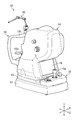
- FIG. 1 is a front perspective view of the ophthalmic apparatus 10 of the first embodiment as viewed from the subject side.
- FIG. 2 is a rear perspective view of the ophthalmic apparatus 10 as seen from the examiner's side.
- the X direction in the figure is the left-right direction with respect to the subject (the eye width direction of the subject E shown in FIG. 4), the Y direction is the vertical direction, and the Z direction is before approaching the subject. It is a front-back direction (also called a working distance direction) parallel to the direction and the rear direction away from the subject.
- the ophthalmic apparatus 10 is a combination of a fundus camera and an optical coherence tomography that obtains an OCT image that is a tomographic image using optical coherence tomography (OCT). It is a compound machine.
- the ophthalmologic apparatus 10 acquires (measures, photographs, observes, etc.) a fundus photographed image and an OCT image of the fundus Ef (see FIG. 4) as the eye characteristics of the eye to be inspected E (see FIG. 4).
- the ophthalmic apparatus 10 includes a base 11, a face support portion 12, a gantry 13, and a measurement head 14.
- a gantry 13 is provided on the base 11. Further, the arithmetic control unit 22 (see FIG. 4) and the like, which will be described later, are stored in the base 11.
- the face support portion 12 is provided integrally with the base 11 at a position on the front side of the measurement head 14 in the Z direction.
- the face support portion 12 has a chin rest 12a and a forehead pad 12b whose positions can be adjusted in the Y direction (vertical direction), and an ophthalmologist such as a measurement head 14 (objective lens 43 described later) or the like can measure the face of the subject. Support at a position facing the device body.
- the face support portion 12 is provided with an electric elevating mechanism 12c corresponding to the support position changing mechanism of the present invention.
- the electric elevating mechanism 12c is a known actuator such as a motor drive mechanism, and is covered by moving the jaw support 12a and the forehead pad 12b in the Y direction under the control of the arithmetic control unit 22 (see FIG. 4) described later. Change the support position of the examiner's face.
- the face support portion 12 is provided with an external fixation lamp 15.
- the external fixation lamp 15 has a light source that emits fixation light, and the position of the light source and the emission direction of the fixation light can be arbitrarily adjusted.
- the external fixation lamp 15 is used for external fixation.
- the eye E (see FIG. 4) to be inspected is rotated in an arbitrary direction by adjusting the position of the light source of the external fixation lamp 15, or is rotated more than when internal fixation is performed, or inside.
- This is a fixation method in which the direction of the eye E to be examined is adjusted by guiding the line of sight of the eye to be inspected E or a companion eye when the fixation cannot be performed.
- the gantry 13 is provided so as to be movable in the X direction and the Z direction (front-back, left-right direction) with respect to the base 11.
- An operation unit 16 is provided on the gantry 13.
- a measurement head 14 is provided on the gantry 13 so as to be movable in the Y direction.
- the gantry 13 is provided with an electric drive mechanism 17 (see FIG. 4) corresponding to the relative movement mechanism of the present invention.
- the electric drive mechanism 17 is a known actuator such as a motor drive mechanism, and under the control of an arithmetic control unit 22 (see FIG. 4) described later, the gantry 13 is moved in the XZ direction and the measurement head 14 is moved in the Y direction. Let me. As a result, the measurement head 14 is moved relative to the eye E to be inspected in the XYZ direction.
- the operation unit 16 is provided on the gantry 13 at a position on the rear side (inspector side) of the measurement head 14 in the Z direction.
- the operation unit 16 is provided with an operation lever 16a in addition to an operation button for performing various operations of the ophthalmic apparatus 10.
- the operation lever 16a is an operation member for manually moving the measurement head 14 in each direction of XYZ.
- the measurement head 14 is moved in the Z direction or the X direction by the above-mentioned electric drive mechanism 17 (see FIG. 4).
- the operation lever 16a is rotated around its longitudinal axis, the measurement head 14 is moved in the Y direction (vertical direction) by the electric drive mechanism 17 according to the rotation operation direction.
- the measuring head 14 constitutes the main body of the ophthalmic apparatus of the present invention.
- the fundus camera unit 14a and the OCT unit 14b shown in FIG. 4 to be described later are built in the measurement head 14.
- a monitor 18 is provided on the back surface of the measurement head 14 on the rear side (examiner side) in the Z direction.
- a lens accommodating portion 19 is provided in front of the measurement head 14 on the front side (subject side) in the Z direction.
- the monitor 18 for example, a touch panel type liquid crystal display device is used.
- the monitor 18 displays various imaging data of the eye E (see FIG. 4), input screens for various setting operations, and the like.
- FIG. 3 is a front view of the lens accommodating portion 19.
- the lens accommodating portion 19 accommodates an objective lens 43 that constitutes a part of the fundus camera unit 14a (see FIG. 4) and has an optical axis OA parallel to the Z direction.
- the lens accommodating portion 19 is provided with eight fixation holes 19a (also referred to as fixation lamps) arranged at equal intervals along the circumferential direction of the objective lens 43 so as to surround the objective lens 43. There is.
- Each fixation hole 19a selectively emits fixation light in the Z direction according to the operation by the operation unit 16.
- Each fixation hole 19a is used for peripheral fixation and imaging of the corner angle (edge of the iris) of the eye E (see FIG. 4).
- Peripheral fixation is a fixation method in which the eye E to be inspected is largely rotated in a desired direction by selectively lighting each fixation hole 19a.
- a stereo camera 20 corresponding to the plurality of cameras of the present invention is provided in front of the measurement head 14 and in the vicinity of the lens accommodating portion 19.
- the stereo camera 20 has a first camera 20a and a second camera 20b.
- the first camera 20a and the second camera 20b are arranged so as to sandwich the objective lens 43 from the left and right sides of the measurement head 14 on the front side surface in the Z direction (the surface facing the eye E to be inspected).
- FIG. 4 is a schematic view showing an example of the configuration of the measurement head 14 of the ophthalmic apparatus 10.
- the measurement head 14 includes a fundus camera unit 14a, an OCT unit 14b, a stereo camera 20, an arithmetic control unit 22, and the like.
- the fundus camera unit 14a has an optical system substantially similar to that of a conventional fundus camera, and obtains (photographs) various observation images of the anterior segment Ea of the eye to be inspected E through the objective lens 43, and the eye to be inspected E is photographed.
- the fundus photographed image of the fundus Ef is acquired as the eye characteristic of.
- the OCT unit 14b acquires an OCT image of the fundus Ef as an eye characteristic of the eye E to be inspected through a part of the optical system of the objective lens 43 and the fundus camera unit 14a. Therefore, the fundus camera unit 14a functions as the eye characteristic acquisition unit and the anterior eye portion observation system of the present invention. Further, the OCT unit 14b functions as an eye characteristic acquisition unit of the present invention.
- the arithmetic control unit 22 is housed in the base 11 (may be in the measurement head 14), and is an arithmetic processing device such as a personal computer that executes various arithmetic processes and control processes.
- the fundus camera unit 14a includes an illumination optical system 30 and an imaging optical system 50 as optical systems for acquiring an observation image of the anterior segment Ea and the like and a fundus photographed image which is a two-dimensional image showing the surface morphology of the fundus Ef. Be prepared.
- the illumination optical system 30 irradiates the fundus Ef with illumination light.
- the image pickup optical system 50 guides the fundus reflection light of the illumination light reflected by the fundus Ef to, for example, CMOS (Complementary Metal Oxide Semiconductor) type or CCD (Charge Coupled Device) type image pickup elements 57 and 60. Further, the imaging optical system 50 guides the signal light output from the OCT optical system 80 (OCT unit 14b) to the fundus Ef, and guides the signal light passing through the fundus Ef to the OCT optical system 80.
- CMOS Complementary Metal Oxide Semiconductor
- CCD Charge Coupled Device
- the illumination optical system 30 includes an observation light source 31, a reflection mirror 32, a condenser lens 33, a visible cut filter 34, a photographing light source 35, a mirror 36, a relay lens 37, 38, an aperture 39, a relay lens 40, a perforated mirror 41, and a dichroic filter.
- a mirror 42, an objective lens 43, and the like are provided.
- the imaging optical system 50 includes a focusing lens 51, a mirror 52, a half mirror 53, an optotype display unit 54, a dichroic mirror 55, and a focusing lens. It includes a lens 56, an image pickup element 57, a mirror 58, a condenser lens 59, an image pickup element 60, and the like.
- observation light source 31 for example, a halogen lamp or an LED (light LED diode) or the like is used, and the observation illumination light is emitted.
- the observation illumination light emitted from the observation light source 31 is reflected by the reflection mirror 32 and passes through the visible cut filter 34 via the condenser lens 33 to become near-infrared light.
- the observation illumination light transmitted through the visible cut filter 34 is once focused in the vicinity of the photographing light source 35, reflected by the mirror 36, and passes through the relay lenses 37, 38, the aperture 39, and the relay lens 40. Then, the observation illumination light is reflected by the peripheral portion of the perforated mirror 41 (the region around the perforated portion), passes through the dichroic mirror 42, and is further refracted by the objective lens 43 to illuminate the fundus Ef.
- the fundus reflection light of the observation illumination light is refracted by the objective lens 43, passes through the dichroic mirror 42, the hole formed in the central region of the perforated mirror 41, and the focusing lens 51, and then is reflected by the mirror 52. .. Further, the reflected light from the fundus of the eye is transmitted through the half mirror 53 and then reflected by the dichroic mirror 55, so that the condensing lens 56 forms an image on the light receiving surface of the image sensor 57.
- the image sensor 57 captures (receives) the fundus reflected light and outputs the image pickup signal to the arithmetic control unit 22 described later.
- the arithmetic control unit 22 causes the monitor 18 to display various observation images based on the image pickup signal output from the image pickup device 57.
- the focus of the imaging optical system 50 is adjusted to the anterior segment Ea of the eye to be inspected E
- the observation image of the anterior segment Ea is displayed on the monitor 18, and the focus of the imaging optical system 50 is adjusted to the fundus Ef. If so, the observation image of the fundus Ef is displayed on the monitor 18.
- the photographing light source 35 for example, a xenon lamp or an LED light source is used, and the photographing illumination light is emitted.
- the photographing illumination light emitted from the photographing light source 35 irradiates the fundus Ef through the same path as the observation illumination light described above.
- the fundus reflected light of the photographing illumination light is guided to the dichroic mirror 55 through the same path as the fundus reflected light of the observation illumination light, passes through the dichroic mirror 55, and is reflected by the mirror 58 to be condensed.
- the lens 59 forms an image on the light receiving surface of the image pickup element 60.
- the image sensor 60 captures (receives) the fundus reflected light and outputs the image pickup signal to the arithmetic control unit 22 described later.
- the arithmetic control unit 22 causes the monitor 18 to display a fundus photographed image based on the image pickup signal output from the image pickup element 60.
- the monitor 18 that displays various observation images and the monitor 18 that displays the fundus photography image may be the same or different from each other.
- the optotype display unit 54 is used for internal fixation that projects the fixation light of the fixation target (bright spot image) onto the eye E to be examined through the objective lens 43.
- the dot matrix liquid crystal display (LCD: Liquid Crystal) Display) and matrix light emitting diode (LED) and the like are used.
- the optotype display unit 54 displays a fixed optotype.
- the optotype display unit 54 can arbitrarily set the display mode (shape, etc.) and display position of the fixed optotype.
- the fundus camera unit 14a includes a focus optical system 70.
- the focus optical system 70 generates a split index for focusing on the fundus Ef.
- the focus optical system 70 includes an LED 71, a relay lens 72, a split index plate 73, a two-hole aperture 74, a mirror 75, and a condenser lens 76. And a reflective rod 77.
- the reflective surface of the reflective rod 77 is set on the optical path of the illumination optical system 30 when the focus is adjusted by the focus optical system 70.
- the focus light emitted from the LED 71 passes through the relay lens 72, is separated into two light beams by the split index plate 73, and then is reflected by the reflection rod 77 through the two-hole aperture 74, the mirror 75, and the condenser lens 76. Once imaged on the surface, it is reflected toward the relay lens 40 on this reflecting surface. Further, the focus light is projected onto the fundus Ef via the relay lens 40, the perforated mirror 41, the dichroic mirror 42, and the objective lens 43.
- the fundus reflected light of the focus light passes through the holes of the objective lens 43, the dichroic mirror 42, and the perforated mirror 41, and after a part of the light passes through the dichroic mirror 55, the focusing lens 51, the mirror 52, and the half mirror
- the image is taken by the image pickup element 57 via the 53, the dichroic mirror 55, and the condenser lens 56.
- the image sensor 57 captures the fundus reflected light of the focus light and outputs an image pickup signal.
- the split index is displayed on the monitor 18 together with the observed image.
- the dichroic mirror 42 branches the optical path of the OCT optical system 80 from the optical path for fundus photography.
- the dichroic mirror 42 reflects light in the wavelength band used for OCT measurement and transmits light for fundus photography.
- a collimator lens unit 81, an optical path length changing unit 82, a galvano scanner 83, a focusing lens 84, a mirror 85, and a relay lens 86 are arranged in this order from the OCT unit 14b side. Is provided.
- the optical path length changing unit 82 includes, for example, a corner cube and a mechanism for moving the corner cube.
- the optical path length changing unit 82 is movable in the direction of the arrow shown in the drawing, and changes the optical path length of the OCT optical system 80. This change in the optical path length is used for correcting the optical path length according to the axial length of the eye E to be inspected, adjusting the interference state, and the like.
- the galvano scanner 83 changes the traveling direction of the signal light passing through the optical path of the OCT optical system 80. As a result, the fundus Ef can be scanned with the signal light.
- the galvano scanner 83 includes, for example, a galvano mirror that scans signal light in the X direction, a galvano mirror that scans in the Y direction, and a mechanism that independently drives them. As a result, the signal light can be scanned in any direction on the XY plane.
- the OCT unit 14b includes an interference optical system used for acquiring an OCT image of the fundus Ef. Similar to the known OCT device, the OCT unit 14b divides the low coherence light into the reference light and the signal light, and causes the signal light via the fundus Ef and the reference light via the reference optical path to interfere with each other to generate the interference light. It is generated and the spectral component of this interference light is detected. The detection result (detection signal) by the OCT unit 14b is output to the arithmetic control unit 22. Since the specific configuration of the OCT unit 14b is a known technique (see, for example, Patent Document 1 above), a specific description thereof will be omitted here.
- the reference numeral OB in the drawing is the optical axis of the first camera 20a and the second camera 20b.
- the first camera 20a continuously captures the anterior segment Ea from one direction in the left-right direction, and outputs the anterior segment image D1 (see FIG. 5), which is an observation image of the anterior segment Ea, to the arithmetic control unit 22. ..
- the second camera 20b continuously photographs the anterior segment Ea from the other direction side in the left-right direction, and outputs the anterior segment image D2 (see FIG. 5), which is an observation image of the anterior segment Ea, to the arithmetic control unit 22. ..
- the arrangement of the first camera 20a and the second camera 20b may be reversed.
- anterior segment images D1 and D2 are a face support determination (also referred to as a chin receiving determination), which is a determination of whether or not the subject's face is properly (appropriately) supported by the face support portion 12, and an eye to be inspected. It is used for auto-alignment of the measuring head 14 with respect to E.
- a face support determination also referred to as a chin receiving determination
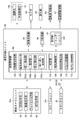
- FIG. 5 is a functional block diagram of the arithmetic control unit 22 of the first embodiment.
- the arithmetic control unit 22 includes a general control unit 90, a storage unit 92, an image forming unit 94, a data processing unit 96, and the like. Further, the arithmetic control unit 22 includes the above-mentioned electric elevating mechanism 12c, fundus camera unit 14a, OCT unit 14b, external fixation lamp 15, operation unit 16, electric drive mechanism 17, monitor 18, fixation hole 19a, and the like. A stereo camera 20 or the like is connected.
- the storage unit 92 stores the image data of the OCT image, the image data of the fundus image, the eye examination information (including the subject information), and the like, in addition to the control program executed by the general control unit 90.
- the storage unit 92 stores the template 120, which will be described later.
- the image forming unit 94 constitutes the eye characteristic acquisition unit of the present invention together with the OCT unit 14b, and analyzes the detection signal input from the OCT unit 14b to form an OCT image of the fundus Ef. Since the specific method for forming the OCT image is the same as that of the conventional OCT apparatus, the description thereof is omitted here.
- the data processing unit 96 uses the OCT image formed by the image forming unit 94, the fundus photographed image and various observation images acquired by the fundus camera unit 14a, the anterior ocular segment images D1 and D2 acquired by the stereo camera 20, and the like. Image processing or the like is performed on the surface.
- the integrated control unit 90 controls the operation of each unit of the ophthalmic apparatus 10 in an integrated manner.
- the integrated control unit 90 executes face support determination based on the anterior eye portion images D1 and D2 input from the stereo camera 20, and when it is determined that the face is properly supported by the face support unit 12, the front Auto-alignment is performed based on the eye images D1 and D2.
- the overall control unit 90 controls the fundus camera unit 14a and the OCT unit 14b after the auto-alignment to acquire the fundus photographed image and the OCT image of the fundus Ef.
- FIG. 5 illustrates only the functions related to face support determination, auto-alignment, and acquisition of eye characteristics (fundus photography image and OCT image) of the eye E to be inspected, and other functions are known techniques and are specific. The illustration is omitted.
- the function of the integrated control unit 90 is realized by using various processors.
- Various processors include CPU (Central Processing Unit), GPU (Graphics Processing Unit), ASIC (Application Specific Integrated Circuit), and programmable logic devices [for example, SPLD (Simple Programmable Logic Devices), CPLD (Complex Programmable Logic Device), And FPGA (Field Programmable Gate Arrays)] and the like are included.
- the various functions of the integrated control unit 90 may be realized by one processor, or may be realized by a plurality of processors of the same type or different types.
- the integrated control unit 90 detects the anterior eye image acquisition unit 100, the pupil image detection unit 102, the determination unit 104, the notification control unit 106, and the relative position detection when acquiring the eye characteristics (fundus photography image and OCT image) of the eye to be inspected E. It functions as a unit 108, an alignment control unit 110, and an eye characteristic acquisition control unit 112.
- what is described as “-part” of the arithmetic control unit 22 may be "-circuit", “-device”, or "-equipment”. That is, what is described as "-part” may be composed of firmware, software, hardware, or a combination thereof.
- the anterior segment image acquisition unit 100 is used for both face support determination and auto-alignment, and serves as an image input interface that is wiredly or wirelessly connected to the first camera 20a and the second camera 20b of the stereo camera 20, respectively. Function.
- the anterior segment image acquisition unit 100 repeatedly acquires anterior segment images D1 and D2 from the first camera 20a and the second camera 20b that continuously photograph the anterior segment Ea, and acquires the anterior segment images D1 and D1, respectively.
- D2 is repeatedly output to the pupil image detection unit 102 and the relative position detection unit 108.
- the pupil image detection unit 102 is used for face support determination.
- the pupil image detection unit 102 is based on the anterior eye image D1 and D2 repeatedly input from the anterior eye image acquisition unit 100, and the pupil image 116 which is an image of the pupil of the eye to be inspected E from the anterior eye image D1 and D2.
- the detection process for detecting (see FIG. 6) is repeatedly executed for each of the anterior segment images D1 and D2.
- the detection process of the pupil image 116 by the pupil image detection unit 102 is different from the detection process of the pupil image 116 by the relative position detection unit 108 at the time of auto-alignment described later, and the pupil is within the range of the fixation tremor of the eye E to be inspected. As long as the image 116 can be detected, this is a simple process.
- the pupil image detection unit 102 functions as a first detection unit 102a, an estimation unit 102b, a second detection unit 102c, and a repetition control unit 102d.
- FIG. 6 is an explanatory diagram for explaining the detection process of the pupil image 116 by the first detection unit 102a.
- the first detection unit 102a detects the pupil image 116 from the anterior segment image D1 captured by the first camera 20a.
- the first camera 20a and the second camera 20b the one that captures a clearer image of the anterior segment Ea may be referred to as the "first camera 20a", and the rest may be referred to as the "second camera 20b".
- the first detection unit 102a performs, for example, a known binarization process, a labeling process, and a filter process based on circularity on the full-size anterior segment image D1.
- the labeling process is a process of assigning consecutive white pixels or black pixels to the same label (assigning the same number) in each pixel of the binarized anterior segment image D1.
- the circularity filtering process is a process of detecting a region in which the circularity is equal to or higher than a predetermined value from the anterior segment image D1 after the labeling process.
- the first detection unit 102a can detect the pupil image 116 from the anterior eye portion image D1, and outputs the detection result indicating the shape and position of the pupil image 116 to the estimation unit 102b.
- the method of detecting the pupil image 116 from the anterior segment image D1 by the first detection unit 102a is not limited to the above-mentioned methods (binarization treatment, labeling treatment, and filter treatment), and is a known method. May be used, and a simple detectable method is particularly preferable.
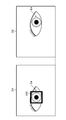
- FIG. 7 is an explanatory diagram for explaining the creation of the template 120 by the estimation unit 102b.
- the estimation unit 102b is based on the detection result of the pupil image 116 in the anterior segment image D1 by the first detection unit 102a, and the anterior segment image D2 by the second detection unit 102c described later.
- a template 120 used for detecting the pupil image 116 from the inside (template matching) is created.
- the estimation unit 102b estimates the shape of the pupil image 116 in the anterior segment image D2 based on the shape of the pupil image 116 in the anterior segment image D1 detected by the first detection unit 102a. Shape information 120a corresponding to this estimation result is created.
- the estimation unit 102b estimates the existence range 118 of the pupil image 116 in the anterior segment image D2 based on the position of the pupil image 116 in the anterior segment image D1 detected by the first detection unit 102a. , The existence range information 120b corresponding to this estimation result is created.
- This existence range 118 indicates the range in which the pupil image 116 that moves in the anterior segment image D2 in response to the fixation tremor of the eye E to be inspected exists. In FIG. 7 (the same applies to FIG. 8 described later), the existence range 118 is exaggerated from the actual drawing in order to prevent the drawings from becoming complicated.
- the method of generating the existence range information 120b is not particularly limited, but the positional relationship between the first camera 20a and the second camera 20b and the shooting magnification are known. Therefore, the estimation unit 102b can estimate the position of the pupil image 116 in the anterior segment image D2 based on the position of the pupil image 116 in the anterior segment image D1 detected by the first detection unit 102a. .. Further, it is possible to determine in advance how much the pupil image 116 is displaced in the anterior segment image D2 according to the fixation tremor of the eye E to be inspected by an experiment or a simulation.
- the estimation unit 102b determines the detection result of the first detection unit 102a, the positional relationship and imaging magnification of the first camera 20a and the second camera 20b, and the displacement amount of the pupil image 116 according to the fixation tremor of the eye E to be inspected. Based on the above, the existence range 118 can be estimated and the existence range information 120b can be created.
- the estimation unit 102b creates a template 120 including the shape information 120a and the existence range information 120b, and stores the template 120 in the storage unit 92.
- FIG. 8 is an explanatory diagram for explaining the detection process of the pupil image 116 from the anterior segment image D2 by the second detection unit 102c.
- the second detection unit 102c is based on the template 120 (shape information 120a and existence range information 120b) stored in the storage unit 92, and is subjected to known template matching to the anterior segment of the eye.
- the pupil image 116 is detected from within the existence range 118 of the image D2.
- the second detection unit 102c identifies the existence range 118 in the anterior segment image D2 based on the existence range information 120b, and the pupil image 116 having a shape corresponding to the shape information 120a from the existence range 118. Perform detection.
- the second detection unit 102c performs detection processing of the pupil image 116 similar to that of the first detection unit 102a described above, so that the presence range 118 in the anterior ocular segment image D2 can be detected.
- the pupil image 116 may be detected.
- the first detection unit 102a detects the pupil image 116 from the anterior eye image D1
- the estimation unit 102b creates the template 120
- the second detection unit 102c detects the pupil image D2 (existence range 118). The detection of the pupil image 116 is repeatedly executed.
- the determination unit 104 makes a face support determination based on the repeated detection result by the second detection unit 102c.
- the face of the subject is properly supported by the face support portion 12
- the movement of the face is substantially suppressed. Therefore, even if the pupil image 116 in the anterior segment image D2 moves in the anterior segment image D2 in response to the fixation tremor of the eye E to be inspected, the pupil image 116 stays within the existence range 118 for a certain period of time.
- the face of the subject is not properly supported by the face support portion 12 such as the face of the subject floating from the chin rest 12a, the movement of the face occurs.
- the determination unit 104 determines the presence or absence of the movement of the face supported by the face support unit 12 for a predetermined fixed time based on the repeated detection result by the second detection unit 102c, thereby determining the face.
- a face support determination is made to determine whether or not the face is properly supported by the support portion 12.
- the determination unit 104 determines whether or not the number of continuous detections of the pupil image 116 from within the existence range 118 of the anterior segment image D2 has reached a predetermined number based on the repeated detection results by the second detection unit 102c. That is, it is determined whether or not the detection of the pupil image 116 from within the existence range 118 is continued (continuous) for a predetermined period of time or longer.
- the determination unit 104 determines that the subject's face supported by the face support unit 12 does not move, and determines that the face does not move. It is determined that the face is properly supported by the support portion 12. On the contrary, when the detection of the pupil image 116 from the existence range 118 does not continue for a certain period of time or more, the determination unit 104 determines that the subject's face is moving while being supported by the face support unit 12. , It is determined that the face is not properly supported by the face support portion 12.
- the determination unit 104 determines that the face is properly supported by the face support unit 12
- the determination unit 104 outputs the determination result to the relative position detection unit 108 and the alignment control unit 110. Further, when the determination unit 104 determines that the face is not properly supported by the face support unit 12, the determination unit 104 outputs the determination result to the notification control unit 106.
- FIG. 9 is an explanatory diagram showing an example of display (notification) of warning information 124 by the monitor 18.
- the notification control unit 106 provides warning information 124 indicating that the face is not properly supported by the face support unit 12. Display on the monitor 18. As a result, the warning information 124 is notified to the examiner. Therefore, in this case, the notification control unit 106 and the monitor 18 function as the notification unit of the present invention.
- a warning message may be output from the speaker (not shown).
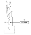
- FIG. 10 is an explanatory diagram showing an example of notifying the subject that the face of the subject is not properly supported by the face support portion 12.
- the notification control unit 106 drives the electric elevating mechanism 12c to, for example, move the chin rest 12a and the forehead pad 12b in the Y direction. By moving it up and down, the support position of the face by the chin rest 12a or the like is changed. As a result, it is possible to notify the subject that the face is not properly supported by the face support portion 12. Therefore, in this case, the notification control unit 106 and the face support unit 12 function as the notification unit of the present invention.
- the relative position detection unit 108 and the alignment control unit 110 are used for auto alignment, and operate in response to the input of the determination result from the determination unit 104.
- the relative position detection unit 108 detects the pupil image 116 (pupil region, pupil shape) from the anterior segment images D1 and D2, respectively, based on the anterior segment images D1 and D2 input from the anterior segment image acquisition unit 100.
- the feature position of each pupil image 116 corresponding to the center of the pupil or the apex of the cornea is specified.
- the relative position detection unit 108 uses a known method (Japanese Patent Laid-Open No. 2013-248376) based on the positions and imaging magnifications of the first camera 20a and the second camera 20b and the feature positions of each of the anterior segment images D1 and D2.
- the relative position (three-dimensional position) of the eye E to be inspected with respect to the measuring head 14 is calculated in (see JP).
- the relative position detection unit 108 outputs this calculation result to the alignment control unit 110 as a detection result of the relative position of the eye E to be inspected.
- the detection process of the pupil image 116 from the anterior segment images D1 and D2 by the relative position detection unit 108 is different from the detection process by the first detection unit 102a at the time of the face support determination described above, and has the above-mentioned features. This is a precision process that requires accurate location identification.
- the relative position detection unit 108 performs, for example, binarization processing of the anterior segment images D1 and D2, and precisely calculates the relative position of the eye E to be inspected from the anterior segment images D1 and D2 after the binarization processing.
- the alignment control unit 110 drives the electric drive mechanism 17 based on the detection result of the relative position of the eye to be inspected E by the relative position detection unit 108 to execute the auto-alignment of the measurement head 14 with respect to the eye to be inspected E.
- the eye characteristic acquisition control unit 112 operates after the completion of the auto-alignment to acquire the eye characteristics of the eye E to be inspected (fundus photographed image and OCT image of the fundus Ef). Specifically, the eye characteristic acquisition control unit 112 drives the fundus camera unit 14a to acquire a fundus photographed image of the fundus Ef. Further, the eye characteristic acquisition control unit 112 drives the OCT optical system 80, the OCT unit 14b, the image forming unit 94, and the like to acquire an OCT image of the fundus Ef.
- FIG. 11 is a flowchart showing a flow of an eye characteristic acquisition process of the eye E to be inspected by the ophthalmic device 10 of the first embodiment having the above configuration, particularly a face support determination process according to a control method of the ophthalmic device 10 of the present invention.
- the power of the ophthalmic apparatus 10 is turned on by the examiner, or when the measurement start operation (capture operation) is executed by the operation unit 16, the acquisition of the eye characteristics of the eye E to be inspected starts. (Step S1).
- the overall control unit 90 starts continuous shooting of the anterior segment Ea of the eye E to be inspected by the first camera 20a and the second camera 20b.
- the anterior segment image acquisition unit 100 acquires the anterior segment images D1 and D2 from the first camera 20a and the second camera 20b, respectively, and outputs these anterior segment images D1 and D2 to the pupil image detection unit 102. (Step S2, corresponding to the anterior segment image acquisition step of the present invention).
- the first detection unit 102a binarizes and labels the anterior segment image D1 as shown in FIG.
- the pupil image 116 is detected from the anterior ocular segment image D1, and the detection result of the position and shape is output to the estimation unit 102b (step S3).
- the estimation unit 102b estimates the shape and existence range 118 of the pupil image 116 in the anterior segment image D2 based on the detection result from the first detection unit 102a. Then, the template 120 (shape information 120a and existence range information 120b) is created (step S5). Then, as shown in FIG. 8 described above, the second detection unit 102c detects the pupil image 116 from within the existence range 118 of the anterior segment image D2 by performing template matching based on the template 120. (Step S6).
- step S6 When the pupil image 116 is detected within the existence range 118 of the anterior segment image D2, the repetitive control unit 102d repeatedly executes the above-described processes from step S3 to step S6 (YES in step S6, step S6). NO in S7). If the pupil image 116 is not detected within the existence range 118 of the anterior segment image D2, the process proceeds to step S12 described later (NO in step S6). It should be noted that steps S3 to S6 correspond to the pupil image detection step of the present invention.
- the anterior segment image acquisition unit 100 receives the anterior segment image from the first camera 20a and the second camera 20b until it is determined to be YES in step S7 or NO in step S6. Every time D1 and D2 are acquired repeatedly, the processes from step S3 to step S6 described above are repeatedly executed.
- the determination unit 104 determines that the number of consecutive detections of the pupil image 116 from within the existence range 118 of the anterior segment image D2 reaches a predetermined number based on the repeated detection result by the second detection unit 102c, that is, the pupil image 116. If the detection continues for a predetermined period of time or longer, it is determined that the face is properly supported by the face support portion 12 (YES in step S7, step S8). In addition, step S8 corresponds to the determination step of the present invention together with step S12 described later. Then, the determination unit 104 outputs the determination result that the face is properly supported by the face support unit 12 to the relative position detection unit 108 and the alignment control unit 110. As a result, auto-alignment is automatically started following the face support determination.
- the relative position detection unit 108 detects the relative position of the eye E to be inspected with respect to the measurement head 14 based on the anterior eye image D1 and D2 input from the anterior eye image acquisition unit 100, and the detection result is the alignment control unit 110. Output to (step S9). As a result, the alignment control unit 110 drives the electric drive mechanism 17 based on the detection result of the relative position of the eye E to be inspected to execute the auto-alignment of the measurement head 14 with respect to the eye E to be inspected (step S10).
- the eye characteristic acquisition control unit 112 drives the fundus camera unit 14a to acquire a fundus photographed image of the fundus Ef, and drives the OCT optical system 80, the OCT unit 14b, the image forming unit 94, and the like. Then, an OCT image of the fundus Ef is acquired. As a result, the acquisition of the eye characteristics of the eye E to be inspected is completed (step S11).
- the face of the determination unit 104 is appropriate due to the face support unit 12. It is determined that the face is not supported by (step S12). Then, the determination unit 104 outputs the determination result that the face is not properly supported by the face support unit 12 to the notification control unit 106.
- the notification control unit 106 Upon receiving the input of the determination result from the determination unit 104, the notification control unit 106 displays the warning information 124 on the monitor 18 or drives the electric elevating mechanism 12c as shown in FIGS. 9 and 10 described above. Then, the jaw receiver 12a and the like are moved up and down in the Y direction. As a result, the face support unit 12 notifies the examiner and the examinee that the face of the examinee is not properly supported (step S13). Then, the examiner alerts the examinee so that the subject's face is properly supported by the face support portion 12, or adjusts the position of the chin rest 12a or the like.
- the processes after step S1 are repeatedly executed.
- the face support determination and auto-alignment can be performed using the anterior segment images D1 and D2 captured by the first camera 20a and the second camera 20b, the face support determination process and the auto-alignment process ( Detection of the relative position of the eye to be inspected E) can be performed in parallel.
- the repeat control unit 102d of the pupil image detection unit 102 of the first embodiment repeatedly acquires the anterior segment images D1 and D2 from the first camera 20a and the second camera 20b each time the anterior segment image acquisition unit 100 repeatedly acquires the anterior segment images D1 and D2 from the first camera 20a and the second camera 20b.
- the first detection unit 102a, the estimation unit 102b, and the second detection unit 102c are repeatedly operated.
- the first detection unit 102a detects the pupil image 116 from the anterior eye image D1
- the estimation unit 102b creates the template 120
- the second detection unit 102c detects the pupil image 116 from the anterior eye image D2. (Template matching) is executed repeatedly.
- the template 120 generated based on the first anterior segment image D1 is used (diverted) from the second and subsequent anterior segment images D2 by the second detection unit 102c.
- the detection (template matching) of the pupil image 116 is repeatedly executed.
- the ophthalmic apparatus 10 of the second embodiment has basically the same configuration as the ophthalmic apparatus 10 of the first embodiment except that the functions of the anterior ocular segment image acquisition unit 100 and the repetitive control unit 102d are different. Therefore, those having the same function or configuration as the first embodiment are designated by the same reference numerals and the description thereof will be omitted.
- the anterior segment image acquisition unit 100 of the second embodiment includes the first image acquisition process of acquiring the anterior segment images D1 and D2 from the first camera 20a and the second camera 20b, and the first image acquisition process. 2
- the second and subsequent image acquisition processes for repeatedly acquiring the anterior segment image D2 from the camera 20b are executed.
- the repetitive control unit 102d of the second embodiment has a second pupil image 116 each time the pupil image 116 is detected from within the existence range 118 of the anterior eye portion image D2 by the second detection unit 102c until the determination unit 104 makes a determination.
- the detection unit 102c is repeatedly operated.
- FIG. 12 is a flowchart showing the flow of the process of acquiring the eye characteristics of the eye E to be inspected by the ophthalmic device 10 of the second embodiment, particularly the face support determination process according to the control method of the ophthalmic device 10 of the present invention. Since the processes from step S1 to step S7 and the processes after step S8 are basically the same as those of the first embodiment shown in FIG. 11, the description thereof will be omitted.
- the anterior segment image acquisition unit 100 acquires the anterior segment image D2 from the second camera 20b and outputs the anterior segment image D2 to the second detection unit 102c ( Step S7A). In this case, the operation of the first camera 20a may or may not be stopped.
- the repetitive control unit 102d of the second embodiment repeatedly operates the second detection unit 102c.
- the second detection unit 102c executes template matching based on the template 120 generated by the estimation unit 102b after the first image acquisition process, and the anterior segment image D2 acquired in the second image acquisition process.
- the pupil image 116 is detected from (steps S5 and S6).
- step S7A by the anterior segment image acquisition unit 100
- step S5 and S6 by the second detection unit 102c
- steps S5 and S6 Is repeatedly executed.
- the pupil image 116 is detected from the anterior segment image D2 acquired in the second and subsequent image acquisition processes based on the template 120 generated by the estimation unit 102b after the first image acquisition process. Can be executed.
- the second and subsequent face support determination processes acquisition of the anterior segment image D1, detection of the pupil image 116 from the anterior segment image D1, and generation of the template 120 can be omitted. As a result, the time required for the second and subsequent face support determination processes is shortened.
- FIG. 13 is a functional block diagram of the arithmetic control unit 22 of the ophthalmic apparatus 10 of the third embodiment.
- the notification control unit 106 notifies the determination result.
- the face support determination process is executed again.
- the ophthalmic apparatus 10 of the third embodiment is the ophthalmic apparatus of each of the above-described embodiments, except that the integrated control unit 90 further functions as the support position change control unit 130 and the redetermination control unit 132. It has basically the same configuration as 10. Therefore, those having the same function or configuration as each of the above embodiments are designated by the same reference numerals and the description thereof will be omitted.
- FIG. 14 is a flowchart showing the flow of the process of acquiring the eye characteristics of the eye E to be inspected by the ophthalmic device 10 of the third embodiment, particularly the face support determination process according to the control method of the ophthalmic device 10 of the present invention. Since the processes from step S1 to step S12 are basically the same as the processes of the second embodiment shown in FIG. 12 described above, a specific description thereof will be omitted.
- the support position change control unit 130 when the determination unit 104 determines that the face is not properly supported by the face support unit 12 (step S12), the support position change control unit 130 operates.
- the support position change control unit 130 drives the electric elevating mechanism 12c to change the face support position of the subject by the face support unit 12, for example, the face support position is changed to the upper side in the Y direction (step S14). ).
- the support position change control unit 130 drives the electric elevating mechanism 12c to raise the face support position by the face support unit 12 by about 5 mm.
- the support position change control unit 130 monitors (detects) the position of the pupil image 116 within at least one of the anterior eye image D1 and D2 acquired by the anterior eye image acquisition unit 100, and the position of the pupil image 116. Is changed, the electric elevating mechanism 12c is driven to change the face support position by the face support portion 12 upward in the Y direction at a low speed.
- the support position of the subject's face may be changed to the lower side instead of the upper side in the Y direction.
- the support of the subject's face by the face support portion 12 is appropriate from an improper state. It is possible to change the state to a normal state, or to alert the subject that the face is not properly supported by the face support portion 12.
- the re-determination control unit 132 sets each unit (anterior eye image acquisition unit 100, pupil image detection unit 102, and determination unit 104) of the overall control unit 90.
- the above-described processes from step S1 to step S7A are repeatedly executed.
- the face support determination process described in the second embodiment is repeatedly executed.
- the processes described in steps S1 to S7 may be repeatedly executed.
- step S7 the processes from step S14, step S1 to step S7A (step S7) are repeatedly executed until the determination unit 104 determines that the face is properly supported by the face support unit 12.
- the face support determination process is repeatedly executed after changing the face support position by the face support portion 12.
- the ophthalmic apparatus 10 can be automatically transferred to the next and subsequent processes (steps S9 to S11) without the examiner performing any operation. As a result, the labor of the examiner can be reduced.
- the stereo camera 20 (first camera 20a and second camera 20b) has been described as an example, but the eye E may be photographed by a plurality of cameras of three or more.
- the anterior segment image acquisition unit 100 captures the anterior segment image D1 captured by the first camera 20a among the plurality of cameras and one or more second cameras 20b among the plurality of cameras.
- the anterior segment image D2 and the obtained anterior segment image D2 are repeatedly acquired.
- the first detection unit 102a detects the pupil image 116 for each anterior segment image D1 captured by the first camera 20a.
- the estimation unit 102b estimates the existence range 118 (creates the template 120) for each anterior segment image D2 captured by one or more second cameras 20b.
- the second detection unit 102c detects the pupil image 116 from within the existence range 118 for each one or more anterior eye image D2. Then, the determination unit 104 determines whether or not the number of continuous detections of the pupil image 116 from within the existence range 118 has reached a predetermined number for each one or more anterior segment images D2.
- the pupil image detection unit 102 detects the pupil image 116 for each of the front eye images D1 and D2 based on the anterior eye image D1 and D2 continuously photographed by the first camera 20a and the second camera 20b. And the face support determination by the determination unit 104 are executed, but only one camera may be used for the face support determination.
- the anterior segment image acquisition unit 100 continuously captures the anterior segment image D1 or the anterior segment image D2 (hereinafter, a single anterior eye) taken by either the first camera 20a or the second camera 20b. (Called a part image) is repeatedly acquired.
- the pupil image detection unit 102 repeatedly detects the pupil image 116 for each single anterior segment image.
- the determination unit 104 continues a state in which the position of the pupil image 116 in the single anterior segment image falls within the range corresponding to the fixation tremor of the eye E to be inspected (corresponding to the above-mentioned existing range 118) for a certain period of time. Face support is determined based on whether or not to do so. As a result, the face support determination can be performed using one camera.
- the anterior segment image acquisition unit 100 can continuously photograph the anterior segment Ea through the objective lens 43 from the imaging optical system 50 (corresponding to the anterior segment observation system of the present invention) to the anterior segment Ea.
- the observation image may be acquired repeatedly.
- the face support determination can be performed by the same method as when either one of the first camera 20a and the second camera 20b is used.
- the arithmetic control unit 22 is built in the measurement head 14, but may be provided outside the base 11 and the measurement head 14. That is, the ophthalmic apparatus 10 of the present invention is also applied to an apparatus corresponding to remote medical care.
- the acquisition of the fundus photograph image and the OCT image of the fundus Ef has been described as an example for acquiring the eye characteristics of the eye E to be inspected, but the ophthalmoflex force, the intraocular pressure, and the corneal endothelium of the eye E to be inspected have been described.
- the present invention can also be applied to an ophthalmic apparatus 10 that acquires various ocular characteristics such as the number of cells and the shape of the cornea.
- Ophthalmic apparatus 12 Face support 12a ... Jaw support 12b ... Forehead support 12c ... Electric elevating mechanism 14 ... Measuring head 14a ... Fundus camera unit 14b ... OCT unit 16 ... Operation unit 17 ... Electric drive mechanism 18 ... Monitor 20 ... Stereo Camera 20a ... First camera 20b ... Second camera 22 ... Arithmetic control unit 30 ... Illumination optical system 43 ... Objective lens 50 ... Imaging optical system 70 ... Focus optical system 80 ... OCT optical system 90 ... General control unit 100 ... Anterior eye unit Image acquisition unit 102 ... Pupil image detection unit 102a ... First detection unit 102b ... Estimating unit 102c ... Second detection unit 102d ...
Landscapes
- Health & Medical Sciences (AREA)
- Life Sciences & Earth Sciences (AREA)
- Engineering & Computer Science (AREA)
- Medical Informatics (AREA)
- Surgery (AREA)
- Biophysics (AREA)
- Biomedical Technology (AREA)
- Heart & Thoracic Surgery (AREA)
- Physics & Mathematics (AREA)
- Molecular Biology (AREA)
- Ophthalmology & Optometry (AREA)
- Animal Behavior & Ethology (AREA)
- General Health & Medical Sciences (AREA)
- Public Health (AREA)
- Veterinary Medicine (AREA)
- Signal Processing (AREA)
- Eye Examination Apparatus (AREA)
Priority Applications (3)
| Application Number | Priority Date | Filing Date | Title |
|---|---|---|---|
| EP20882438.3A EP4052635A4 (en) | 2019-10-29 | 2020-09-30 | OPHTHALMIC DEVICE AND METHOD FOR CONTROLLING IT |
| CN202080074739.0A CN114615922B (zh) | 2019-10-29 | 2020-09-30 | 眼科装置及其控制方法 |
| US17/730,188 US12402788B2 (en) | 2019-10-29 | 2022-04-27 | Ophthalmologic device and method for controlling same |
Applications Claiming Priority (2)
| Application Number | Priority Date | Filing Date | Title |
|---|---|---|---|
| JP2019-196011 | 2019-10-29 | ||
| JP2019196011A JP7537869B2 (ja) | 2019-10-29 | 2019-10-29 | 眼科装置 |
Related Child Applications (1)
| Application Number | Title | Priority Date | Filing Date |
|---|---|---|---|
| US17/730,188 Continuation US12402788B2 (en) | 2019-10-29 | 2022-04-27 | Ophthalmologic device and method for controlling same |
Publications (1)
| Publication Number | Publication Date |
|---|---|
| WO2021085020A1 true WO2021085020A1 (ja) | 2021-05-06 |
Family
ID=75711749
Family Applications (1)
| Application Number | Title | Priority Date | Filing Date |
|---|---|---|---|
| PCT/JP2020/037225 Ceased WO2021085020A1 (ja) | 2019-10-29 | 2020-09-30 | 眼科装置及びその制御方法 |
Country Status (5)
| Country | Link |
|---|---|
| US (1) | US12402788B2 (https=) |
| EP (1) | EP4052635A4 (https=) |
| JP (1) | JP7537869B2 (https=) |
| CN (1) | CN114615922B (https=) |
| WO (1) | WO2021085020A1 (https=) |
Families Citing this family (6)
| Publication number | Priority date | Publication date | Assignee | Title |
|---|---|---|---|---|
| JP2023076025A (ja) * | 2021-11-22 | 2023-06-01 | キヤノン株式会社 | 眼科装置、眼科装置の制御方法、及びプログラム |
| JPWO2024202211A1 (https=) | 2023-03-28 | 2024-10-03 | ||
| WO2024202213A1 (ja) | 2023-03-28 | 2024-10-03 | 株式会社トプコン | 眼科装置及び眼科装置の作動方法 |
| JPWO2024202212A1 (https=) | 2023-03-28 | 2024-10-03 | ||
| WO2024202210A1 (ja) | 2023-03-28 | 2024-10-03 | 株式会社トプコン | 眼科装置及び眼科装置の作動方法 |
| JP2024173368A (ja) * | 2023-06-02 | 2024-12-12 | 株式会社トプコン | 眼科装置 |
Citations (5)
| Publication number | Priority date | Publication date | Assignee | Title |
|---|---|---|---|---|
| JPH11342110A (ja) * | 1998-05-29 | 1999-12-14 | Canon Inc | 検眼装置の顎受け台 |
| JP2013150696A (ja) * | 2012-01-25 | 2013-08-08 | Canon Inc | 眼科装置および制御方法並びにプログラム |
| JP2013248376A (ja) | 2012-05-01 | 2013-12-12 | Topcon Corp | 眼科装置 |
| JP2014161652A (ja) * | 2013-02-27 | 2014-09-08 | Canon Inc | 検査装置、その制御方法およびプログラム |
| JP2014200678A (ja) | 2013-04-03 | 2014-10-27 | 株式会社トプコン | 眼科装置 |
Family Cites Families (11)
| Publication number | Priority date | Publication date | Assignee | Title |
|---|---|---|---|---|
| JP3935834B2 (ja) * | 2002-11-29 | 2007-06-27 | 株式会社ニデック | 眼科装置 |
| JP5807371B2 (ja) * | 2011-04-21 | 2015-11-10 | 株式会社ニデック | 眼科撮影装置 |
| JP5279153B1 (ja) * | 2012-10-19 | 2013-09-04 | 正一 中村 | 瞳孔位置測定方法及び両用レンズの作製方法 |
| JP2016049261A (ja) * | 2014-08-29 | 2016-04-11 | アルプス電気株式会社 | 照明撮像装置および視線検出装置 |
| EP3260040B1 (en) * | 2016-06-03 | 2021-09-08 | Nidek Co., Ltd. | Ophthalmic apparatus |
| EP3632297B1 (en) * | 2017-05-24 | 2025-11-12 | Osaka University | Ophthalmic device and method for operating ophthalmic device |
| JP2018051340A (ja) * | 2017-11-24 | 2018-04-05 | 株式会社トプコン | 眼科装置 |
| JP7325169B2 (ja) * | 2017-12-28 | 2023-08-14 | 株式会社トプコン | 眼科装置、及びその制御方法 |
| JP7080076B2 (ja) * | 2018-03-16 | 2022-06-03 | 株式会社トプコン | 眼科装置、及びその制御方法 |
| JP7029992B2 (ja) | 2018-03-23 | 2022-03-04 | 株式会社トプコン | 眼科装置の操作端末、眼科検査の方法およびプログラム |
| JP7575216B2 (ja) * | 2020-08-25 | 2024-10-29 | 株式会社トプコン | 眼科画像処理装置、眼科装置、画質評価方法及びプログラム |
-
2019
- 2019-10-29 JP JP2019196011A patent/JP7537869B2/ja active Active
-
2020
- 2020-09-30 EP EP20882438.3A patent/EP4052635A4/en active Pending
- 2020-09-30 CN CN202080074739.0A patent/CN114615922B/zh active Active
- 2020-09-30 WO PCT/JP2020/037225 patent/WO2021085020A1/ja not_active Ceased
-
2022
- 2022-04-27 US US17/730,188 patent/US12402788B2/en active Active
Patent Citations (5)
| Publication number | Priority date | Publication date | Assignee | Title |
|---|---|---|---|---|
| JPH11342110A (ja) * | 1998-05-29 | 1999-12-14 | Canon Inc | 検眼装置の顎受け台 |
| JP2013150696A (ja) * | 2012-01-25 | 2013-08-08 | Canon Inc | 眼科装置および制御方法並びにプログラム |
| JP2013248376A (ja) | 2012-05-01 | 2013-12-12 | Topcon Corp | 眼科装置 |
| JP2014161652A (ja) * | 2013-02-27 | 2014-09-08 | Canon Inc | 検査装置、その制御方法およびプログラム |
| JP2014200678A (ja) | 2013-04-03 | 2014-10-27 | 株式会社トプコン | 眼科装置 |
Also Published As
| Publication number | Publication date |
|---|---|
| US20220248947A1 (en) | 2022-08-11 |
| JP7537869B2 (ja) | 2024-08-21 |
| CN114615922B (zh) | 2025-08-22 |
| US12402788B2 (en) | 2025-09-02 |
| CN114615922A (zh) | 2022-06-10 |
| EP4052635A1 (en) | 2022-09-07 |
| JP2021069415A (ja) | 2021-05-06 |
| EP4052635A4 (en) | 2023-08-30 |
Similar Documents
| Publication | Publication Date | Title |
|---|---|---|
| CN114615922B (zh) | 眼科装置及其控制方法 | |
| JP5850292B2 (ja) | 眼科装置 | |
| JP6641730B2 (ja) | 眼科装置、および眼科装置用プログラム | |
| JP7080076B2 (ja) | 眼科装置、及びその制御方法 | |
| JP7459491B2 (ja) | 眼科測定装置 | |
| US12232812B2 (en) | Fundus camera and control method of the same | |
| JP7266375B2 (ja) | 眼科装置及びその作動方法 | |
| JP6634765B2 (ja) | 眼科装置、および眼科装置制御プログラム | |
| JP7430082B2 (ja) | 眼科装置及びその作動方法 | |
| JP7550586B2 (ja) | 眼科装置及びその作動方法 | |
| JP7607099B2 (ja) | 眼科装置 | |
| JP5643662B2 (ja) | 眼科装置 | |
| JP7187769B2 (ja) | 眼科装置、および眼科装置制御プログラム | |
| JP2017196304A (ja) | 眼科装置、および眼科装置制御プログラム | |
| JP2017023416A (ja) | 眼科撮影装置及びその制御方法、並びに、プログラム | |
| JP7344351B2 (ja) | 眼科装置及びその作動方法 | |
| JP6844949B2 (ja) | 眼科装置 | |
| US12402789B2 (en) | Ophthalmic apparatus, method of controlling ophthalmic apparatus, and recording medium | |
| JP7553190B2 (ja) | 眼科装置及びその作動方法 | |
| JP2022105110A (ja) | 眼科装置 | |
| JP2017051430A (ja) | 眼科装置及びその制御方法、並びに、プログラム | |
| JP2017051429A (ja) | 眼科装置及びその制御方法、並びに、プログラム | |
| JP2022109637A (ja) | 眼科撮影装置及びミラー筐体 | |
| JP2014094119A (ja) | 眼科撮影装置及び方法 | |
| JP2021027876A (ja) | 眼科装置 |
Legal Events
| Date | Code | Title | Description |
|---|---|---|---|
| 121 | Ep: the epo has been informed by wipo that ep was designated in this application |
Ref document number: 20882438 Country of ref document: EP Kind code of ref document: A1 |
|
| NENP | Non-entry into the national phase |
Ref country code: DE |
|
| ENP | Entry into the national phase |
Ref document number: 2020882438 Country of ref document: EP Effective date: 20220530 |
|
| WWG | Wipo information: grant in national office |
Ref document number: 202080074739.0 Country of ref document: CN |