WO2021084649A1 - インクジェットヘッド及びインクジェットヘッドの製造方法 - Google Patents
インクジェットヘッド及びインクジェットヘッドの製造方法 Download PDFInfo
- Publication number
- WO2021084649A1 WO2021084649A1 PCT/JP2019/042575 JP2019042575W WO2021084649A1 WO 2021084649 A1 WO2021084649 A1 WO 2021084649A1 JP 2019042575 W JP2019042575 W JP 2019042575W WO 2021084649 A1 WO2021084649 A1 WO 2021084649A1
- Authority
- WO
- WIPO (PCT)
- Prior art keywords
- alcohol
- epoxy resin
- inkjet head
- adhesive
- curing agent
- Prior art date
- Legal status (The legal status is an assumption and is not a legal conclusion. Google has not performed a legal analysis and makes no representation as to the accuracy of the status listed.)
- Ceased
Links
Images

Classifications
-
- B—PERFORMING OPERATIONS; TRANSPORTING
- B41—PRINTING; LINING MACHINES; TYPEWRITERS; STAMPS
- B41J—TYPEWRITERS; SELECTIVE PRINTING MECHANISMS, i.e. MECHANISMS PRINTING OTHERWISE THAN FROM A FORME; CORRECTION OF TYPOGRAPHICAL ERRORS
- B41J2/00—Typewriters or selective printing mechanisms characterised by the printing or marking process for which they are designed
- B41J2/005—Typewriters or selective printing mechanisms characterised by the printing or marking process for which they are designed characterised by bringing liquid or particles selectively into contact with a printing material
- B41J2/01—Ink jet
- B41J2/135—Nozzles
- B41J2/16—Production of nozzles
- B41J2/1621—Manufacturing processes
- B41J2/1623—Manufacturing processes bonding and adhesion
-
- B—PERFORMING OPERATIONS; TRANSPORTING
- B41—PRINTING; LINING MACHINES; TYPEWRITERS; STAMPS
- B41J—TYPEWRITERS; SELECTIVE PRINTING MECHANISMS, i.e. MECHANISMS PRINTING OTHERWISE THAN FROM A FORME; CORRECTION OF TYPOGRAPHICAL ERRORS
- B41J2/00—Typewriters or selective printing mechanisms characterised by the printing or marking process for which they are designed
- B41J2/005—Typewriters or selective printing mechanisms characterised by the printing or marking process for which they are designed characterised by bringing liquid or particles selectively into contact with a printing material
- B41J2/01—Ink jet
- B41J2/135—Nozzles
- B41J2/16—Production of nozzles
- B41J2/1607—Production of print heads with piezoelectric elements
- B41J2/1609—Production of print heads with piezoelectric elements of finger type, chamber walls consisting integrally of piezoelectric material
-
- B—PERFORMING OPERATIONS; TRANSPORTING
- B41—PRINTING; LINING MACHINES; TYPEWRITERS; STAMPS
- B41J—TYPEWRITERS; SELECTIVE PRINTING MECHANISMS, i.e. MECHANISMS PRINTING OTHERWISE THAN FROM A FORME; CORRECTION OF TYPOGRAPHICAL ERRORS
- B41J2/00—Typewriters or selective printing mechanisms characterised by the printing or marking process for which they are designed
- B41J2/005—Typewriters or selective printing mechanisms characterised by the printing or marking process for which they are designed characterised by bringing liquid or particles selectively into contact with a printing material
- B41J2/01—Ink jet
- B41J2/135—Nozzles
- B41J2/14—Structure thereof only for on-demand ink jet heads
- B41J2/14201—Structure of print heads with piezoelectric elements
- B41J2/14209—Structure of print heads with piezoelectric elements of finger type, chamber walls consisting integrally of piezoelectric material
-
- B—PERFORMING OPERATIONS; TRANSPORTING
- B41—PRINTING; LINING MACHINES; TYPEWRITERS; STAMPS
- B41J—TYPEWRITERS; SELECTIVE PRINTING MECHANISMS, i.e. MECHANISMS PRINTING OTHERWISE THAN FROM A FORME; CORRECTION OF TYPOGRAPHICAL ERRORS
- B41J2/00—Typewriters or selective printing mechanisms characterised by the printing or marking process for which they are designed
- B41J2/005—Typewriters or selective printing mechanisms characterised by the printing or marking process for which they are designed characterised by bringing liquid or particles selectively into contact with a printing material
- B41J2/01—Ink jet
- B41J2/135—Nozzles
- B41J2/14—Structure thereof only for on-demand ink jet heads
- B41J2/1433—Structure of nozzle plates
-
- B—PERFORMING OPERATIONS; TRANSPORTING
- B41—PRINTING; LINING MACHINES; TYPEWRITERS; STAMPS
- B41J—TYPEWRITERS; SELECTIVE PRINTING MECHANISMS, i.e. MECHANISMS PRINTING OTHERWISE THAN FROM A FORME; CORRECTION OF TYPOGRAPHICAL ERRORS
- B41J2/00—Typewriters or selective printing mechanisms characterised by the printing or marking process for which they are designed
- B41J2/005—Typewriters or selective printing mechanisms characterised by the printing or marking process for which they are designed characterised by bringing liquid or particles selectively into contact with a printing material
- B41J2/01—Ink jet
- B41J2/135—Nozzles
- B41J2/16—Production of nozzles
- B41J2/162—Manufacturing of the nozzle plates
-
- B—PERFORMING OPERATIONS; TRANSPORTING
- B41—PRINTING; LINING MACHINES; TYPEWRITERS; STAMPS
- B41J—TYPEWRITERS; SELECTIVE PRINTING MECHANISMS, i.e. MECHANISMS PRINTING OTHERWISE THAN FROM A FORME; CORRECTION OF TYPOGRAPHICAL ERRORS
- B41J2/00—Typewriters or selective printing mechanisms characterised by the printing or marking process for which they are designed
- B41J2/005—Typewriters or selective printing mechanisms characterised by the printing or marking process for which they are designed characterised by bringing liquid or particles selectively into contact with a printing material
- B41J2/01—Ink jet
- B41J2/135—Nozzles
- B41J2/16—Production of nozzles
- B41J2/1621—Manufacturing processes
- B41J2/1632—Manufacturing processes machining
- B41J2/1634—Manufacturing processes machining laser machining
-
- B—PERFORMING OPERATIONS; TRANSPORTING
- B41—PRINTING; LINING MACHINES; TYPEWRITERS; STAMPS
- B41J—TYPEWRITERS; SELECTIVE PRINTING MECHANISMS, i.e. MECHANISMS PRINTING OTHERWISE THAN FROM A FORME; CORRECTION OF TYPOGRAPHICAL ERRORS
- B41J2/00—Typewriters or selective printing mechanisms characterised by the printing or marking process for which they are designed
- B41J2/005—Typewriters or selective printing mechanisms characterised by the printing or marking process for which they are designed characterised by bringing liquid or particles selectively into contact with a printing material
- B41J2/01—Ink jet
- B41J2/135—Nozzles
- B41J2/16—Production of nozzles
- B41J2/1621—Manufacturing processes
- B41J2/164—Manufacturing processes thin film formation
- B41J2/1642—Manufacturing processes thin film formation thin film formation by CVD [chemical vapor deposition]
-
- B—PERFORMING OPERATIONS; TRANSPORTING
- B41—PRINTING; LINING MACHINES; TYPEWRITERS; STAMPS
- B41J—TYPEWRITERS; SELECTIVE PRINTING MECHANISMS, i.e. MECHANISMS PRINTING OTHERWISE THAN FROM A FORME; CORRECTION OF TYPOGRAPHICAL ERRORS
- B41J2/00—Typewriters or selective printing mechanisms characterised by the printing or marking process for which they are designed
- B41J2/005—Typewriters or selective printing mechanisms characterised by the printing or marking process for which they are designed characterised by bringing liquid or particles selectively into contact with a printing material
- B41J2/01—Ink jet
- B41J2/135—Nozzles
- B41J2/16—Production of nozzles
- B41J2/1621—Manufacturing processes
- B41J2/164—Manufacturing processes thin film formation
- B41J2/1643—Manufacturing processes thin film formation thin film formation by plating
-
- B—PERFORMING OPERATIONS; TRANSPORTING
- B41—PRINTING; LINING MACHINES; TYPEWRITERS; STAMPS
- B41J—TYPEWRITERS; SELECTIVE PRINTING MECHANISMS, i.e. MECHANISMS PRINTING OTHERWISE THAN FROM A FORME; CORRECTION OF TYPOGRAPHICAL ERRORS
- B41J2/00—Typewriters or selective printing mechanisms characterised by the printing or marking process for which they are designed
- B41J2/005—Typewriters or selective printing mechanisms characterised by the printing or marking process for which they are designed characterised by bringing liquid or particles selectively into contact with a printing material
- B41J2/01—Ink jet
- B41J2/135—Nozzles
- B41J2/16—Production of nozzles
- B41J2/1621—Manufacturing processes
- B41J2/164—Manufacturing processes thin film formation
- B41J2/1646—Manufacturing processes thin film formation thin film formation by sputtering
-
- C—CHEMISTRY; METALLURGY
- C08—ORGANIC MACROMOLECULAR COMPOUNDS; THEIR PREPARATION OR CHEMICAL WORKING-UP; COMPOSITIONS BASED THEREON
- C08G—MACROMOLECULAR COMPOUNDS OBTAINED OTHERWISE THAN BY REACTIONS ONLY INVOLVING UNSATURATED CARBON-TO-CARBON BONDS
- C08G59/00—Polycondensates containing more than one epoxy group per molecule; Macromolecules obtained by polymerising compounds containing more than one epoxy group per molecule using curing agents or catalysts which react with the epoxy groups
- C08G59/18—Macromolecules obtained by polymerising compounds containing more than one epoxy group per molecule using curing agents or catalysts which react with the epoxy groups ; e.g. general methods of curing
- C08G59/182—Macromolecules obtained by polymerising compounds containing more than one epoxy group per molecule using curing agents or catalysts which react with the epoxy groups ; e.g. general methods of curing using pre-adducts of epoxy compounds with curing agents
- C08G59/184—Macromolecules obtained by polymerising compounds containing more than one epoxy group per molecule using curing agents or catalysts which react with the epoxy groups ; e.g. general methods of curing using pre-adducts of epoxy compounds with curing agents with amines
-
- C—CHEMISTRY; METALLURGY
- C08—ORGANIC MACROMOLECULAR COMPOUNDS; THEIR PREPARATION OR CHEMICAL WORKING-UP; COMPOSITIONS BASED THEREON
- C08G—MACROMOLECULAR COMPOUNDS OBTAINED OTHERWISE THAN BY REACTIONS ONLY INVOLVING UNSATURATED CARBON-TO-CARBON BONDS
- C08G59/00—Polycondensates containing more than one epoxy group per molecule; Macromolecules obtained by polymerising compounds containing more than one epoxy group per molecule using curing agents or catalysts which react with the epoxy groups
- C08G59/18—Macromolecules obtained by polymerising compounds containing more than one epoxy group per molecule using curing agents or catalysts which react with the epoxy groups ; e.g. general methods of curing
- C08G59/20—Macromolecules obtained by polymerising compounds containing more than one epoxy group per molecule using curing agents or catalysts which react with the epoxy groups ; e.g. general methods of curing characterised by the epoxy compounds used
- C08G59/22—Di-epoxy compounds
- C08G59/24—Di-epoxy compounds carbocyclic
- C08G59/245—Di-epoxy compounds carbocyclic aromatic
-
- C—CHEMISTRY; METALLURGY
- C08—ORGANIC MACROMOLECULAR COMPOUNDS; THEIR PREPARATION OR CHEMICAL WORKING-UP; COMPOSITIONS BASED THEREON
- C08G—MACROMOLECULAR COMPOUNDS OBTAINED OTHERWISE THAN BY REACTIONS ONLY INVOLVING UNSATURATED CARBON-TO-CARBON BONDS
- C08G59/00—Polycondensates containing more than one epoxy group per molecule; Macromolecules obtained by polymerising compounds containing more than one epoxy group per molecule using curing agents or catalysts which react with the epoxy groups
- C08G59/18—Macromolecules obtained by polymerising compounds containing more than one epoxy group per molecule using curing agents or catalysts which react with the epoxy groups ; e.g. general methods of curing
- C08G59/68—Macromolecules obtained by polymerising compounds containing more than one epoxy group per molecule using curing agents or catalysts which react with the epoxy groups ; e.g. general methods of curing characterised by the catalysts used
- C08G59/686—Macromolecules obtained by polymerising compounds containing more than one epoxy group per molecule using curing agents or catalysts which react with the epoxy groups ; e.g. general methods of curing characterised by the catalysts used containing nitrogen
-
- C—CHEMISTRY; METALLURGY
- C09—DYES; PAINTS; POLISHES; NATURAL RESINS; ADHESIVES; COMPOSITIONS NOT OTHERWISE PROVIDED FOR; APPLICATIONS OF MATERIALS NOT OTHERWISE PROVIDED FOR
- C09J—ADHESIVES; NON-MECHANICAL ASPECTS OF ADHESIVE PROCESSES IN GENERAL; ADHESIVE PROCESSES NOT PROVIDED FOR ELSEWHERE; USE OF MATERIALS AS ADHESIVES
- C09J163/00—Adhesives based on epoxy resins; Adhesives based on derivatives of epoxy resins
-
- B—PERFORMING OPERATIONS; TRANSPORTING
- B41—PRINTING; LINING MACHINES; TYPEWRITERS; STAMPS
- B41J—TYPEWRITERS; SELECTIVE PRINTING MECHANISMS, i.e. MECHANISMS PRINTING OTHERWISE THAN FROM A FORME; CORRECTION OF TYPOGRAPHICAL ERRORS
- B41J2/00—Typewriters or selective printing mechanisms characterised by the printing or marking process for which they are designed
- B41J2/005—Typewriters or selective printing mechanisms characterised by the printing or marking process for which they are designed characterised by bringing liquid or particles selectively into contact with a printing material
- B41J2/01—Ink jet
- B41J2/135—Nozzles
- B41J2/14—Structure thereof only for on-demand ink jet heads
- B41J2002/14362—Assembling elements of heads
-
- B—PERFORMING OPERATIONS; TRANSPORTING
- B41—PRINTING; LINING MACHINES; TYPEWRITERS; STAMPS
- B41J—TYPEWRITERS; SELECTIVE PRINTING MECHANISMS, i.e. MECHANISMS PRINTING OTHERWISE THAN FROM A FORME; CORRECTION OF TYPOGRAPHICAL ERRORS
- B41J2/00—Typewriters or selective printing mechanisms characterised by the printing or marking process for which they are designed
- B41J2/005—Typewriters or selective printing mechanisms characterised by the printing or marking process for which they are designed characterised by bringing liquid or particles selectively into contact with a printing material
- B41J2/01—Ink jet
- B41J2/135—Nozzles
- B41J2/14—Structure thereof only for on-demand ink jet heads
- B41J2002/14491—Electrical connection
Definitions
- the present invention relates to an inkjet head and a method for manufacturing an inkjet head. More specifically, the present invention contains an epoxy resin as a main agent and an imidazole-based curing agent as a curing agent, so that a time for joining work can be secured before curing, and long-term reliability (use environment).
- the present invention relates to an inkjet head and a method for manufacturing an inkjet head using an adhesive having excellent resistance to temperature fluctuations.
- Inkjet heads that eject ink in the form of minute droplets are widely used as recording heads for inkjet printers that eject ink droplets onto a recording medium to record characters and images.
- a piezoelectric body is placed in a pressurizing chamber, or a voltage is applied to a part of the constituent members of the pressurizing chamber as a piezoelectric body to deform the ink and apply pressure to the ink.
- a method of discharging the ink and a method of arranging an electric resistor in a pressurizing chamber to supply a current to generate heat to vaporize and expand the water content in the ink to apply pressure to the ink to discharge the ink.
- the spacing between adjacent nozzles of inkjet heads has become extremely narrow due to the high density of recorded images.
- dpi means the number of dots per inch
- the distance between adjacent nozzles is 140 ⁇ m.
- the thickness of the pressure chamber partition wall is 70 ⁇ m
- the width of the pressure chamber is 70 ⁇ m.
- the inkjet head is configured by joining each member such as a nozzle plate and a pressure chamber partition wall to each other with a thermosetting adhesive.
- a thermosetting adhesive By using an adhesive, it is possible to increase the density, and the degree of freedom in selecting the material of the constituent members is also increased.
- the adhesive used for the inkjet head needs to have high durability against ink (solvent) after curing.
- an adhesive having a high crosslink density due to curing and high solvent resistance an adhesive containing an epoxy resin and a chain polymerization type curing agent (imidazoles) is known.
- Patent Document 1 describes an inkjet head configured by using an adhesive containing novolak or bisphenol F epoxy resin, alicyclic amine, and alcohol. This adhesive can be cured at low temperature and has high adhesive strength and solvent resistance.
- Patent Document 2 describes an inkjet head configured by using an adhesive containing a novolak epoxy resin, a photocuring agent, and a microencapsulated curing agent. With this adhesive, it is possible to achieve both productivity due to photocurability and solvent resistance of adhesive strength.
- the adhesive containing an epoxy resin and an imidazole-based curing agent is cured by chain polymerization, has a high crosslink density, and has high solvent resistance and elastic modulus after curing, but is hard and brittle, and members of materials having different linear expansion rates are used.
- the bonded inkjet head is subjected to thermal stress and has poor long-term reliability (resistance to temperature fluctuations in the usage environment).
- the thickening rate (viscosity increase rate) can be suppressed, the time for joining work can be secured, and the throughput for assembling the inkjet head can be increased.
- a temperature of 100 ° C. or higher is required to dissolve or destroy the microcapsules (hereinafter, simply referred to as "dissolution"), so that low-temperature curing cannot be performed and the curing temperature becomes high.
- the higher curing temperature impairs long-term reliability due to damage to the components and higher thermal stress in the inkjet head during assembly.
- each member is deformed after the adhesive is cured due to the difference in linear expansion rate between the members, and when the stress due to this deformation exceeds the adhesive force, Peeling occurs at the joint.
- the temperature is even lower. Hardening is required.
- the subject of the present invention is an inkjet head and an inkjet head using an adhesive that contains an epoxy resin as a main agent and an imidazole-based curing agent as a curing agent, can secure a time for joining work before curing, and has excellent long-term reliability.
- the purpose is to provide a manufacturing method.
- An inkjet head in which components are adhered with an epoxy resin as a main agent, an imidazole-based curing agent microencapsulated as a curing agent, and an adhesive containing at least an alcohol that dissolves the microcapsules at a low temperature.
- the inkjet head according to 1 wherein the residue of the microcapsules dissolved by the alcohol is dispersed in the cured epoxy resin.
- 3. The inkjet head according to 1 or 2 above, wherein the alcohol is a high boiling point alcohol. 4.
- Method. 7. The method for producing an inkjet head according to the above 6, wherein the residue of the microcapsules dissolved in the alcohol is dispersed in the epoxy resin to cure the epoxy resin. 8. The method for producing an inkjet head according to the above 6 or 7, wherein a high boiling point alcohol is used as the alcohol. 9. 8. The method for producing an inkjet head according to 8, wherein the boiling point of the high boiling alcohol is 150 ° C. or higher. 10. The method for producing an inkjet head according to any one of 6 to 9, wherein an alcohol having a benzene ring is used as the alcohol.
- an inkjet head and an inkjet head are manufactured using an adhesive containing an epoxy resin as a main agent and an imidazole-based curing agent as a curing agent, which can secure time for joining work before curing and has excellent long-term reliability.
- a method can be provided.
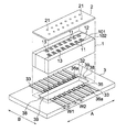
- FIG. 1 Perspective view of the head chip of the inkjet head of the embodiment Top view showing the upper surface of the head tip shown in FIG.
- the inkjet head and the method for manufacturing the inkjet head of the present embodiment are composed of an epoxy resin as a main agent, an imidazole-based curing agent microencapsulated as a curing agent, and an adhesive containing at least an alcohol that dissolves the microcapsules at a low temperature.
- the members are glued together.
- the constituent members of the inkjet head include, but are not limited to, a head chip, a nozzle plate, a wiring board, a flexible board, a manifold, a filter, a housing, and a cap receiving plate.
- the thickening speed can be suppressed, the time for joining work can be secured, and the assembly throughput can be increased.
- FIG. 1 is a perspective view of the head chip of the inkjet head of the embodiment.
- the surface on the side where ink is ejected from the inkjet head (upper side in FIG. 1) is referred to as "lower surface”, and the surface on the opposite side (lower surface in FIG. 1) is referred to as "upper surface”.
- the ink flow direction is from bottom to top.
- the inkjet head of the embodiment is configured to have a rectangular parallelepiped head chip 1 in which a plurality of pressure chambers 12 are formed.
- the head chip 1 is configured such that a flow path member (partition wall) 11 made of a piezoelectric material and a pressure chamber (ink supply path) 12 are alternately arranged side by side.
- a flow path member (partition wall) 11 made of a piezoelectric material and a pressure chamber (ink supply path) 12 are alternately arranged side by side.
- both side walls are formed parallel to each other.
- the outlets and inlets of the pressure chambers 12 are arranged on the lower surface and the upper surface of the head tip 1, respectively, and each pressure chamber 12 is a straight type in which the opening area and the opening shape are substantially the same in the length direction from the inlet to the outlet.
- each pressure chamber 12 constitutes two rows of pressure chambers.
- Each pressure chamber row is composed of eight pressure chambers 12 in the present embodiment, but the number of pressure chambers 12 constituting the pressure chamber row is not limited at all. Further, the shape and arrangement of each pressure chamber 12 are not limited in any way, and may include a dummy channel.
- the head tip 1 is formed by joining a piezoelectric body 101 having a plurality of grooves serving as each pressure chamber 12 and a side wall plate 102 closing the plurality of grooves to each other using an adhesive.
- a drive electrode made of the metal layer 13 shown by the diagonal line in FIG. 1 is formed on the inner surface of the groove of the piezoelectric body 101 (inner surface of the pressure chamber 12).
- the metal layer 13 is preferably covered with a transparent insulating layer in order to prevent corrosion by ink.
- the metal layer 13 acts as a driving electrode for the flow path member 11, and is made of, for example, Ni, Co, Cu, Al, Sn, Cr, or the like. It is preferable to use Al or Cu from the viewpoint of electrical resistance, and it is preferable to use Ni from the viewpoint of corrosion, strength, and cost. A laminated structure in which Au is laminated on Al may be used.
- the metal layer 13 is formed by a method using a vacuum device such as a vapor deposition method, a sputtering method, a plating method, or a CVD (chemical vapor deposition method).
- the thickness of the metal layer 13 is preferably in the range of 0.5 to 5 ⁇ m.
- FIG. 2 is a plan view showing the upper surface of the head tip shown in FIG.
- connection electrode 14 (voltage application electrode) drawn from the metal layer 13 of each pressure chamber 12 is formed on the upper surface of the head chip 1.
- the connection electrode 14 can be formed by vapor deposition or sputtering.
- a nozzle plate 2 is bonded to the lower surface of the head tip 1 using an adhesive.
- nozzles 21 are provided at positions corresponding to the outlets of the pressure chambers 12 of the head tip 1.
- the inlet, outlet and nozzle 21 of each pressure chamber 12 are arranged in a straight line.
- the nozzle plate 2 is preferably made of a material capable of ablation by laser light or a material capable of anisotropic etching.
- resin sheets such as polyimide, polyethylene terephthalate, polyamide, and polysulfone, and silicon can be preferably used.
- a polyimide that can withstand a high temperature for imparting an ink-repellent layer to the surface and can perform precise nozzle processing by laser light.
- a wiring board 3 is bonded to the upper surface of the head chip 1 on which the connection electrode 14 is formed by using an adhesive.
- the wiring board 3 is a plate-shaped member for connecting wiring for applying a drive voltage from a drive circuit (not shown) to each metal layer 13 of the head chip 1.
- the wiring board 3 is a non-polarized ceramic material such as PZT, AlN-BN, AlN, a low thermal expansion plastic or glass, a material obtained by depolarizing the same material as the piezoelectric substrate material used for the head chip 1, and the like. Consists of.
- the material of the wiring board 3 is preferably a material in which the difference in thermal expansion coefficient with respect to the unpolarized PZT is within ⁇ 3 ppm in order to suppress the distortion of the head chip 1 due to the difference in linear expansion coefficient.
- the wiring board 3 is not limited to one plate-shaped one, and may be one in which a plurality of thin plate-shaped substrate materials are laminated to obtain a desired thickness.
- the wiring board 3 is formed in a rectangular shape larger than the upper surface of the head chip 1, and is oriented in the pressure chamber row direction (arrangement direction of the pressure chambers 12, A direction in FIG. 1) and in a direction orthogonal to the pressure chamber row direction (direction in FIG. 1). (Direction B in FIG. 1) Both sides of the head chip 1 project outward from the upper surface.
- each wiring electrode 33 is formed in the same number as each connection electrode 14 formed on the upper surface of the head chip 1 at the same pitch (W1 + W2).
- each wiring electrode 33 is electrically connected to each wiring of the FPC or the like.
- Each wiring electrode 33 connected to each wiring such as an FPC functions as an electrode for applying a drive voltage from a drive circuit (not shown) to the metal layer 13 in the pressure chamber 12 via the connection electrode 14.
- An opening 32 penetrating from the lower surface to the upper surface of the wiring board 3 is formed in the substantially central portion of the wiring board 3.
- the opening 32 has a size that allows the inlet side openings of all the pressure chambers 12 facing the upper surface of the head tip 1 to be exposed to the upper surface side.
- Each wiring electrode 33 is formed from the peripheral edge of the opening 32 to the outer edge of the wiring board 3.
- a dummy electrode 36a located between the wiring electrodes 33 and not involved in driving is formed on the lower surface of the wiring board 3.
- the dummy electrode 36a is formed so that the space between the head chip 1 and the wiring board 3 is sealed by an adhesive.
- a positioning pattern 38 for positioning the head chip 1 is formed on the lower surface of the wiring board 3. When the head chip 1 and the wiring board 3 are joined, the positioning pattern 38 is fitted with the positioning pattern 39 (see FIG. 2) formed on the upper surface of the head chip 1 to form the head chip 1 and the wiring board 3. Perform positioning.
- each connection electrode 14 of the head chip 1 and each wiring electrode 33 of the wiring board 3 are aligned and overlapped so as to be electrically connected. Then, the head chip 1 and the wiring board 3 are joined by heating and pressurizing at a predetermined temperature and a predetermined time to cure the adhesive.
- an adhesive is applied to the adhesive surfaces of the two (the lower surface of the head chip 1 and the upper surface of the nozzle plate 2), and the two are aligned and overlapped to each other at a predetermined temperature and a predetermined temperature. It is done by heating and pressurizing over time to cure the adhesive.
- the amount of the adhesive applied to the surface of the member is not particularly limited, but the wet film thickness when applied is preferably 0.5 ⁇ m or more and 1000 ⁇ m or less. It is more preferably 1.0 ⁇ m or more and 25.0 ⁇ m or less. When the wet film thickness is 0.5 ⁇ m or more, the durability of joining between members can be improved. Further, when the wet film thickness is 1000 ⁇ m or less, the adhesive does not become excessive and the adhesive overflow can be prevented.
- Components other than the above-mentioned members of the inkjet head are also joined to other members using an adhesive to form the inkjet head.
- adhesion of the constituent members of the inkjet head in addition to the above-mentioned adhesion between the upper surface of the head chip 1 and the lower surface of the wiring board 3, the adhesion between the lower surface of the head chip 1 and the upper surface of the nozzle plate 2, the lower end portion of the flexible substrate And the lower surface of the wiring board 3, the wiring board 3 and the manifold (not shown), the manifold and the filter (not shown), the housing (not shown) and the cap receiving plate (not shown), and the like.
- the adhesive used in the present embodiment contains at least an epoxy resin as a main agent, a microencapsulated imidazole-based curing agent as a curing agent, and an alcohol that dissolves the microcapsules at a low temperature.
- an epoxy resin as a main agent
- a microencapsulated imidazole-based curing agent as a curing agent
- an alcohol that dissolves the microcapsules at a low temperature.
- the epoxy resin since the imidazole-based curing agent is microencapsulated, the epoxy resin does not cure unless the microcapsules are dissolved, so that the bonding work time can be secured before the epoxy resin is cured. It is a preferable characteristic of an inkjet head that a large number of members are positioned and bonded to each other so that time can be spent on joining work before curing the epoxy resin.
- this adhesive contains an alcohol that dissolves the microcapsules at a low temperature
- a high temperature such as 100 ° C. or higher in order to dissolve the microcapsules, for example, less than 100 ° C.
- each member does not deform after the adhesive is cured due to the difference in linear expansion coefficient between the members, so that the heat cycle resistance is high and the joint is formed. No peeling occurs.
- Epoxy resin As the epoxy resin applicable to the adhesive in the present embodiment, either a monomer of a compound having an epoxy group or an oligomer thereof can be used. Specific examples thereof include conventionally known aromatic epoxy resins, alicyclic epoxy resins, and aliphatic epoxy resins.
- the epoxy resin means a monomer or an oligomer thereof.
- the epoxy resin preferably contains an aromatic epoxy resin in an amount of 70 to 99% by mass or more in the epoxy resin from the viewpoint of durability against ink.
- the epoxy resin used for the adhesive of the present embodiment may be one kind or a mixture of many kinds.
- a preferred aromatic epoxy resin is a di or polyglycidyl ether produced by the reaction of epichlorohydrin with a polyhydric phenol having at least one aromatic nucleus or an alkylene oxide adduct thereof.
- the aromatic epoxy resin contains a novolak type epoxy resin and, for example, di or polyglycidyl ether of bisphenol A or its polyalkylene oxide adduct, di or of hydrogenated bisphenol A or its polyalkylene oxide adduct. It can contain polyglycidyl ether and at least one of a bisphenol F type epoxy resin, a novolak or an epoxy resin derived from bisphenols.
- bisphenols include bisphenol A type epoxy resin, bisphenol F type epoxy resin, and the like.
- examples of the polyalkylene oxide include polyethylene oxide and polypropylene oxide. Of these, it is preferable to use bisphenol F type epoxy resin as the main agent.
- Novolak type epoxy resin Specific examples of the novolak type epoxy include phenol novolac type epoxy resin, cresol novolak type epoxy resin and the like.
- the novolak type epoxy resin is a compound having a plurality of glycidyl groups in one molecule produced by the reaction between the hydroxyl group of the novolak resin and epichlorohydrin.
- the number of epoxy groups in one molecule has a distribution, and the average value thereof varies depending on the synthesis conditions, but the average number of epoxy groups in one molecule is preferably 3 or more.
- jER152 phenol novolac epoxy resin, manufactured by Japan Epoxy Resin Co., Ltd.
- jER154 phenol novolac epoxy resin, manufactured by Japan Epoxy Resin Co., Ltd.
- EPICLON N-660 cresol novolac epoxy resin, manufactured by Japan Epoxy Resin Co., Ltd.
- DIC Co., Ltd. Etc.
- the polyfunctional epoxy resin is a trifunctional or higher functional epoxy resin excluding novolak epoxy.
- Specific examples of the polyfunctional epoxy resin include triglycidyl-p-aminophenol (92.3) (referred to as TGAP), tetraglycidyl diaminodiphenylmethane (105.5), triglycidyl isocyanurate (99), triglycidyl urazole (89.7), and the like.
- examples thereof include triglycidylaminocresol (97), tetraglycidyl-1,3-diaminomethylcyclohexane (91.5), and the like. Above all, it is preferable to use TGAP.
- the alicyclic epoxy resin is a cyclohexene oxide or cyclopentene obtained by epoxidizing a compound having a cycloalkane ring such as at least one cyclohexene or cyclopentene ring with an appropriate oxidizing agent such as hydrogen peroxide or peracid.
- Oxide-containing compounds can be mentioned. Specific examples thereof include (3,4-epoxycyclohexyl) methyl-3', 4'-epoxycyclohexylcarboxylate, and bis- (2,3-epoxycyclopentyl) ether.
- an imidazole-based curing agent which is a thermal anionic polymerization initiator for heavy addition or thermal polymerization of an epoxy monomer is used.
- imidazole-based curing agent examples include 1-methylimidazole, 1-benzyl-2-methylimidazole, 1,2-dimethylimidazole, 1-isobutyl-2-methylimidazole, 1-methyl-2-ethylimidazole.
- the curing agent is microencapsulated and added to the adhesive.
- the imidazole-based curing agent microcapsules include HXA-3932 (microencapsulating the imidazole-based thermal polymerization initiator with MMA, average particle size 2 ⁇ m, manufactured by Asahi Kasei Chemicals Co., Ltd.), HX-3741 (imidazole-based thermal polymerization).
- Microencapsulate initiator with MMA, average particle size 5 ⁇ m, manufactured by Asahi Kasei Chemicals Co., Ltd., HX-3722 (microencapsulate imidazole-based thermal polymerization initiator with MMA, average particle size 2 ⁇ m, manufactured by Asahi Kasei Chemicals Co., Ltd.) ) Etc. are commercially available.
- microcapsules of these imidazole-based curing agents are preferably added in an amount of 1 to 100 parts by mass, more preferably 10 to 80 parts by mass, based on 100 parts by mass of the epoxy resin.
- microcapsules are dissolved when the epoxy resin is cured, but it is preferable that the microcapsules are not completely dissolved and a part of the microcapsules is dissolved to have a residue (shell).
- the residue after the microcapsules are dissolved is diffused into the epoxy resin and acts as a soft segment after the epoxy resin is cured to improve heat cycle resistance.
- the presence or absence of the residue of the microcapsules in the epoxy resin and the diffusion status can be confirmed by an electron microscope.
- organic matter mapping analysis by FT-IR organic matter can be identified and the existing region can be identified by mapping and analyzing organic matter in a minute region
- TOF-SIMS time-of-flight secondary ion mass spectrometry
- microcapsules and methods for producing microcapsules for example, as described in JP-A-9-3164 ([0005] to [0006]), but in the present invention, the main agent is used. From the viewpoint of dispersing in epoxy resin, shell microcapsules using epoxy resin and isocyanate are preferable.
- the isocyanate serving as a precursor of the microcapsules may be, for example, a compound having two or more isocyanate groups in the molecule as polyvalent isocyanates, and specifically, m-phenylenedi isocyanate, p-phenylenedi isocyanate, 2 , 4-tolylene diisocyanate, 2,6-tolylene diisocyanate, naphthalene-1,4-diisocyanate, diphenylmethane-4,4-diisocyanate, 3,3-dimethoxy-4,4-biphenyldiisocyanate, 3,3-dimethyldiphenylmethane -4,4-diisocyanate, xylylene-1,4-diisocyanate, 4,4-diphenylpropanediisocyanate, trimethylene diisocyanate, hexamethylene diisocyanate, propylene-1,2-diisocyanate, butylene-1,2-
- an adduct of tolylene diisocyanate and trimethylol propane an adduct of xylylene diisocyanate and trimethylol propane, triphenyldi It is preferable to use an isocyanate prepolymer represented by polymethylene polyphenyl isocyanates such as methylene triisocyanate.
- the adhesive may contain a silane coupling agent in order to improve the durability of the adhesive force.
- Preferred compounds of the silane coupling agent include ⁇ - (3,4-epoxycyclohexyl) ethyltrimethoxysilane, ⁇ -glycidoxypropyltrimethoxysilane, ⁇ -glycidoxypropylmethyldimethoxysilane, ⁇ -glycid. Examples thereof include xypropylmethyldiethoxysilane.
- the amount of the silane coupling agent added is preferably 0.5 to 5 parts by mass with respect to 100 parts by mass of the epoxy resin. If it is 0.5 parts by mass or more, the durability of the adhesive force is excellent, and if it is 5 parts by mass or less, the viscosity increase is small when stored at room temperature, and the pot life can be extended.
- alcohols include 4-methoxybenzyl alcohol (boiling point 259 ° C.), 2-phenylethanol (boiling point 219 ° C.), nonyl alcohol (boiling point 214 ° C.), benzyl alcohol (boiling point 205 ° C.), and octyl as high boiling point alcohols.
- Examples of alcohol (boiling point 194 ° C.), hexanol (boiling point 157 ° C.), and low boiling point alcohol include pentanol (boiling point 137 ° C.) and isopropanol (boiling point 82.4 ° C.).
- Benzyl alcohol is particularly preferable.
- Alcohol is preferably 0.1 parts by mass or more and 10 parts by mass or less with respect to 100 parts by mass of the epoxy resin as the main agent. This is because if it is less than 0.1 parts by mass, the solvent resistance becomes poor, and if it exceeds 10 parts by mass, the solvent resistance becomes poor or the heat cycle resistance becomes poor.
- the microcapsules are dissolved at a low temperature (for example, 100 ° C. or lower), so that the epoxy resin can be cured at a low temperature.
- Alcohol also acts as a mediator to uniformly disperse the dissolved microcapsule residue, allowing the microcapsule residue to be used as a soft segment.
- Epoxy resin cured with an imidazole-based curing agent has good solvent resistance, but has a hard and brittle property.
- toughness is imparted to the entire epoxy resin and the hard and brittle property is alleviated.
- the epoxy resin is cured at a low temperature and in a short time, and while maintaining good solvent resistance, it acquires strong properties against thermal stress and greatly improves the long-term reliability of the inkjet head. Can be done.
- the long-term reliability is resistance to temperature fluctuations in the usage environment, and can be confirmed by assembling composite materials having different linear expansions and performing a heat cycle (reliability) test.
- the alcohol is preferably a high boiling point alcohol.
- the boiling point of the high boiling alcohol is preferably 150 ° C. or higher.
- the boiling point alcohol is 150 ° C. or higher, for example, the epoxy resin can be prevented from volatilizing at the curing temperature. As a result, the alcohol remains until the curing of the epoxy resin is completed, so that the microcapsules can be dissolved well. Further, the alcohol remaining until the curing of the epoxy resin is completed makes it possible to disperse the residue of the microcapsules more uniformly.
- the alcohol is an alcohol having a benzene ring.
- An alcohol having a benzene ring can more preferably prevent volatilization of the epoxy resin at the curing temperature and remains until the curing of the epoxy resin is completed, so that microcapsules made of, for example, urethane can be satisfactorily dissolved. Further, the alcohol remaining until the curing of the epoxy resin is completed makes it possible to disperse the residue of the microcapsules more uniformly.
- the alcohol having a benzene ring has a chemical structure similar to that of an epoxy resin (for example, bisphenol type epoxy), it has good compatibility with the epoxy resin, does not adversely affect the physical properties of the epoxy resin, and has a high epoxy resin. Good interposition in the molecular structure.
- an epoxy resin for example, bisphenol type epoxy
- the ink applicable when forming an image using the inkjet printer provided with the inkjet head of the present embodiment is not particularly limited, and examples thereof include water-based ink, non-water-based ink, wax ink, and active-curable ink. it can.
- Such inks include dye inks in which the coloring material is a dye, pigment inks in which the coloring material is insoluble in the solvent constituting the ink and forms a dispersion system containing fine pigment particles, or high-colored inks in which the coloring material is colored.
- a dispersion ink or the like made of a dispersion of a molecular polymer is used.
- an ink having an organic solvent content of 50% or more and 100% or less of the total solvent, and further having a solubility in a resin component is preferable to apply an organic solvent having a high solubility parameter (SP value) of 16.0 or more and 21.0 or less to image formation using an ink containing 30% by mass or more and 100% or less of the total organic solvent.
- SP value solubility parameter
- Ink is composed of coloring materials such as dyes and pigments and organic solvents (solvents) that dissolve them, and the types are not particularly limited.
- Organic solvent It is preferable to use an organic solvent having high solubility in the resin for the ink, but it is necessary that the strength of the inkjet head is maintained even if an organic solvent having high resin solubility is used. It is preferable that this inkjet printer is compatible with an ink in which 50% or more and 100% or less of the total solvent is composed of an organic solvent.
- the SP value (solubility parameter of the organic solvent) is a value represented by the square root of the molecular aggregation energy and is calculated by the Bicerano method.
- the "Bicerano method” is described in Prediction of Polymer Properties (Plastics Engineering, 65) Jozef Bicerano (Author). The unit is (MPa) 1/2 and refers to the value at 25 ° C.
- Examples of the organic solvent having the SP value specified in the present embodiment are also described in "Polymer Handbook", 3rd edition (John Wily & Sons), 1989, VII / 526-539, co-edited by J. Brandup and EHImmergu. Dipole efficiency is calculated by AM1 of MOPAC.
- Color material As the ink in the present embodiment, for example, a coloring material that forms yellow, magenta, cyan, black, blue, green, and red inks is preferably used.
- the ink in the present embodiment may contain various additives.
- Example 1-1 [Preparation of microcapsule type curing agent] 100 parts by mass of bisphenol F type epoxy resin and 100 parts by mass of 2-methylimidazole are reacted at 80 ° C. for 3 hours in 200 parts by mass of a mixed solvent of methanol and toluene, and then the solvent at 180 ° C. under reduced pressure. Was distilled off under reduced pressure to obtain a solid compound.
- the head chip 1, the wiring substrate 3, the head chip 1, and the nozzle plate 2, which are constituent members of the inkjet head shown in FIG. 1, are joined by using the above adhesive, and the adhesive is cured at a curing temperature of 60 ° C. It was adhered to prepare an inkjet head.
- Example 1-2 Inkjet heads and pellets were produced in the same manner as in Example 1-1 except that the curing temperature of the adhesive was 80 ° C.
- Example 1-3 Inkjet heads and pellets were produced in the same manner as in Example 1-1 except that the curing temperature of the adhesive was 100 ° C.
- Example 2 Inkjet heads and pellets were prepared in the same manner as in Example 1-2 except that the alcohol was replaced with hexanol (boiling point 157 ° C.) as the high boiling point alcohol (2).
- Example 3 Inkjet heads and pellets were prepared in the same manner as in Example 1-2, except that the alcohol was replaced with pentanol (boiling point 137 ° C.) as the low boiling point alcohol (1).
- Example 4 Inkjet heads and pellets were prepared in the same manner as in Example 1-2 except that the alcohol was replaced with isopropanol (boiling point 82.4 ° C.) as the low boiling point alcohol (2).
- Example 1-2 Inkjet heads and pellets were prepared in the same manner as in Example 1-2 except that alcohol was not added.
- Example 1-3 Inkjet heads and pellets were prepared in the same manner as in Example 1-3 except that alcohol was not added.
- Example 2-1 Inkjet heads and pellets were prepared in the same manner as in Example 1-1 except that the curing agent was not microencapsulated.
- Example 2-2 Inkjet heads and pellets were prepared in the same manner as in Example 1-2 except that the curing agent was not microencapsulated.
- Example 2-3 Inkjet heads and pellets were prepared in the same manner as in Example 1-3 except that the curing agent was not microencapsulated.
- Example 3-1 Inkjet heads and pellets were prepared in the same manner as in Example 1-1 except that no alcohol was added and the curing agent was not microencapsulated.
- Example 3-2 Inkjet heads and pellets were prepared in the same manner as in Example 1-2 except that no alcohol was added and the curing agent was not microencapsulated.
- Example 3-3 Inkjet heads and pellets were prepared in the same manner as in Example 1-3 except that no alcohol was added and the curing agent was not microencapsulated.
- Example 1-1 contains a microencapsulated curing agent and an alcohol that dissolves the microcapsules at a low temperature, sufficient curing can be performed even at a low temperature of 60 ° C. as compared with the adhesive of Comparative Example 1-1. As a result, the thermal stress in the inkjet head during assembly does not increase, and the components are not damaged by high temperature, so that long-term reliability can be ensured.
- the adhesives of Examples 1-1, 1-2, 1-3, 2, 3, and 4 contain a microencapsulated curing agent and an alcohol that dissolves the microcapsules at a low temperature, the adhesive can be cured at a low temperature of 100 ° C. or lower. Even if members of various materials are joined, each member does not deform after the adhesive is cured due to the difference in linear expansion rate between the members, the heat cycle resistance is high, and the joint may be peeled off. I was able to confirm that there was no such thing.
- the alcohol is preferably a high boiling point alcohol, and the difference between the boiling point of the alcohol and the curing temperature is 120. It was confirmed that the temperature is preferably higher than ° C. This is because the high boiling point alcohol intervenes in the polymer structure of the epoxy resin to soften the cured epoxy resin, relieve the stress of the adhesive part between the members, and heat cycle resistance (reliability) and ink. It is considered that the stability of discharge was improved.
- Example 1-1 contains a microencapsulated curing agent and an alcohol that dissolves the microcapsules at a low temperature
- Comparative Examples 1-1, 2-1 and 3 It was confirmed that, unlike -1, sufficient curing was possible even at a low temperature of 60 ° C., and the viscosity increase rate of the epoxy resin was slowed down so that the bonding work time could be secured before the epoxy resin was cured. It is a preferable characteristic of an inkjet head that a large number of members are positioned and bonded to each other so that time can be spent on joining work before curing the epoxy resin.
Landscapes
- Engineering & Computer Science (AREA)
- Manufacturing & Machinery (AREA)
- Chemical & Material Sciences (AREA)
- Organic Chemistry (AREA)
- Health & Medical Sciences (AREA)
- Chemical Kinetics & Catalysis (AREA)
- Medicinal Chemistry (AREA)
- Polymers & Plastics (AREA)
- Physics & Mathematics (AREA)
- Optics & Photonics (AREA)
- Particle Formation And Scattering Control In Inkjet Printers (AREA)
- Adhesives Or Adhesive Processes (AREA)
Priority Applications (5)
| Application Number | Priority Date | Filing Date | Title |
|---|---|---|---|
| US17/771,315 US11919308B2 (en) | 2019-10-30 | 2019-10-30 | Inkjet head and production method for inkjet head |
| JP2021553958A JP7276490B2 (ja) | 2019-10-30 | 2019-10-30 | インクジェットヘッド及びインクジェットヘッドの製造方法 |
| EP19950822.7A EP4052913B1 (en) | 2019-10-30 | 2019-10-30 | Inkjet head and production method for inkjet head |
| PCT/JP2019/042575 WO2021084649A1 (ja) | 2019-10-30 | 2019-10-30 | インクジェットヘッド及びインクジェットヘッドの製造方法 |
| CN201980101917.1A CN114641396B (zh) | 2019-10-30 | 2019-10-30 | 喷墨头以及喷墨头的制造方法 |
Applications Claiming Priority (1)
| Application Number | Priority Date | Filing Date | Title |
|---|---|---|---|
| PCT/JP2019/042575 WO2021084649A1 (ja) | 2019-10-30 | 2019-10-30 | インクジェットヘッド及びインクジェットヘッドの製造方法 |
Publications (1)
| Publication Number | Publication Date |
|---|---|
| WO2021084649A1 true WO2021084649A1 (ja) | 2021-05-06 |
Family
ID=75714927
Family Applications (1)
| Application Number | Title | Priority Date | Filing Date |
|---|---|---|---|
| PCT/JP2019/042575 Ceased WO2021084649A1 (ja) | 2019-10-30 | 2019-10-30 | インクジェットヘッド及びインクジェットヘッドの製造方法 |
Country Status (5)
| Country | Link |
|---|---|
| US (1) | US11919308B2 (https=) |
| EP (1) | EP4052913B1 (https=) |
| JP (1) | JP7276490B2 (https=) |
| CN (1) | CN114641396B (https=) |
| WO (1) | WO2021084649A1 (https=) |
Cited By (2)
| Publication number | Priority date | Publication date | Assignee | Title |
|---|---|---|---|---|
| JP2023137042A (ja) * | 2022-03-17 | 2023-09-29 | 旭化成株式会社 | 一液性エポキシ樹脂組成物用マスターバッチ型硬化剤、及びエポキシ樹脂組成物 |
| WO2024075602A1 (ja) * | 2022-10-07 | 2024-04-11 | 株式会社スリーボンド | エポキシ樹脂組成物 |
Citations (9)
| Publication number | Priority date | Publication date | Assignee | Title |
|---|---|---|---|---|
| JPS5754378B2 (https=) | 1975-05-27 | 1982-11-17 | ||
| JPH093164A (ja) | 1995-06-15 | 1997-01-07 | Nitto Denko Corp | マイクロカプセル型硬化剤または硬化促進剤、およびそれを含有してなるエポキシ樹脂組成物 |
| JP2004277458A (ja) * | 2003-03-12 | 2004-10-07 | Nagase Chemtex Corp | 1液型エポキシ樹脂組成物およびそれを用いた1液型エポキシ樹脂系接着剤 |
| JP2007269959A (ja) * | 2006-03-31 | 2007-10-18 | Nippon Handa Kk | 導電性接着剤、電子装置およびその製造方法 |
| US20080090943A1 (en) * | 2006-10-16 | 2008-04-17 | Trillion, Inc. | Epoxy compositions |
| JP2011032387A (ja) * | 2009-08-03 | 2011-02-17 | Toppan Forms Co Ltd | 硬化性組成物 |
| JP2011109005A (ja) * | 2009-11-20 | 2011-06-02 | Sumitomo Electric Ind Ltd | 配線板接続体の製造方法、および配線板 |
| WO2011089939A1 (ja) * | 2010-01-22 | 2011-07-28 | コニカミノルタIj株式会社 | インクジェットヘッドの製造方法 |
| JP5279117B2 (ja) | 2008-05-28 | 2013-09-04 | コニカミノルタ株式会社 | インクジェットヘッド |
Family Cites Families (4)
| Publication number | Priority date | Publication date | Assignee | Title |
|---|---|---|---|---|
| JP2000129238A (ja) | 1998-10-26 | 2000-05-09 | Nitto Denko Corp | シート状接着剤組成物およびそれを用いた電子部品装置ならびにそのリペアー方法 |
| JP4237088B2 (ja) * | 2003-07-24 | 2009-03-11 | 東京応化工業株式会社 | 感光性樹脂組成物および該組成物を用いたパターン形成方法 |
| KR100717028B1 (ko) * | 2005-09-13 | 2007-05-10 | 삼성전자주식회사 | 전도성 에폭시 수지를 구비한 잉크젯 프린터 헤드 |
| JP6525630B2 (ja) * | 2015-02-18 | 2019-06-05 | キヤノン株式会社 | 液体吐出ヘッドおよびその製造方法 |
-
2019
- 2019-10-30 CN CN201980101917.1A patent/CN114641396B/zh active Active
- 2019-10-30 EP EP19950822.7A patent/EP4052913B1/en active Active
- 2019-10-30 WO PCT/JP2019/042575 patent/WO2021084649A1/ja not_active Ceased
- 2019-10-30 US US17/771,315 patent/US11919308B2/en active Active
- 2019-10-30 JP JP2021553958A patent/JP7276490B2/ja active Active
Patent Citations (9)
| Publication number | Priority date | Publication date | Assignee | Title |
|---|---|---|---|---|
| JPS5754378B2 (https=) | 1975-05-27 | 1982-11-17 | ||
| JPH093164A (ja) | 1995-06-15 | 1997-01-07 | Nitto Denko Corp | マイクロカプセル型硬化剤または硬化促進剤、およびそれを含有してなるエポキシ樹脂組成物 |
| JP2004277458A (ja) * | 2003-03-12 | 2004-10-07 | Nagase Chemtex Corp | 1液型エポキシ樹脂組成物およびそれを用いた1液型エポキシ樹脂系接着剤 |
| JP2007269959A (ja) * | 2006-03-31 | 2007-10-18 | Nippon Handa Kk | 導電性接着剤、電子装置およびその製造方法 |
| US20080090943A1 (en) * | 2006-10-16 | 2008-04-17 | Trillion, Inc. | Epoxy compositions |
| JP5279117B2 (ja) | 2008-05-28 | 2013-09-04 | コニカミノルタ株式会社 | インクジェットヘッド |
| JP2011032387A (ja) * | 2009-08-03 | 2011-02-17 | Toppan Forms Co Ltd | 硬化性組成物 |
| JP2011109005A (ja) * | 2009-11-20 | 2011-06-02 | Sumitomo Electric Ind Ltd | 配線板接続体の製造方法、および配線板 |
| WO2011089939A1 (ja) * | 2010-01-22 | 2011-07-28 | コニカミノルタIj株式会社 | インクジェットヘッドの製造方法 |
Non-Patent Citations (2)
| Title |
|---|
| "Polymer Handbook", vol. 7, 1989, JOHN WILY & SONS, pages: 526 - 539 |
| See also references of EP4052913A4 |
Cited By (3)
| Publication number | Priority date | Publication date | Assignee | Title |
|---|---|---|---|---|
| JP2023137042A (ja) * | 2022-03-17 | 2023-09-29 | 旭化成株式会社 | 一液性エポキシ樹脂組成物用マスターバッチ型硬化剤、及びエポキシ樹脂組成物 |
| JP7840744B2 (ja) | 2022-03-17 | 2026-04-06 | 旭化成株式会社 | 一液性エポキシ樹脂組成物用マスターバッチ型硬化剤、及びエポキシ樹脂組成物 |
| WO2024075602A1 (ja) * | 2022-10-07 | 2024-04-11 | 株式会社スリーボンド | エポキシ樹脂組成物 |
Also Published As
| Publication number | Publication date |
|---|---|
| EP4052913A1 (en) | 2022-09-07 |
| JPWO2021084649A1 (https=) | 2021-05-06 |
| JP7276490B2 (ja) | 2023-05-18 |
| CN114641396B (zh) | 2024-03-08 |
| US20220402269A1 (en) | 2022-12-22 |
| CN114641396A (zh) | 2022-06-17 |
| EP4052913A4 (en) | 2022-10-19 |
| US11919308B2 (en) | 2024-03-05 |
| EP4052913B1 (en) | 2025-01-08 |
Similar Documents
| Publication | Publication Date | Title |
|---|---|---|
| US7922860B2 (en) | Manufacturing inkjet head by adhering with epoxy resins and alkyl imidazole | |
| JP5780917B2 (ja) | インクジェット記録ヘッド用配線保護封止剤、並びに、それを用いたインクジェット記録ヘッド及びその製造方法 | |
| US8163819B2 (en) | Adhesive compositions, micro-fluid ejection devices and methods for attaching micro-fluid ejection heads | |
| US8439483B2 (en) | Liquid ejection head and method of producing the same | |
| JP7276490B2 (ja) | インクジェットヘッド及びインクジェットヘッドの製造方法 | |
| US10029461B2 (en) | Ink discharging apparatus and ink discharging method | |
| KR101292342B1 (ko) | 액체 토출 헤드 및 그의 제조 방법 | |
| US9004648B2 (en) | Inkjet printheads containing epoxy adhesives and methods for fabrication thereof | |
| JP2006257350A (ja) | 接着剤組成物、インクジェットヘッド及びインクジェットヘッドの製造方法 | |
| JP5754378B2 (ja) | インクジェットヘッドの製造方法 | |
| US12059897B2 (en) | Inkjet recording head and method for producing same | |
| JP4987291B2 (ja) | インクジェットヘッド及びその製造方法 | |
| US7438394B2 (en) | Inkjet head and method for making the same | |
| US20090255438A1 (en) | Thermally curable encapsulant composition for inkjet print cartridge | |
| US10850512B2 (en) | Ink jet recording head and method of manufacturing same | |
| JP2007331334A (ja) | インクジェット記録ヘッド及びその製造方法、並びに、インクジェット記録ヘッド用配線保護封止剤 | |
| CN105015167B (zh) | 一种用于形成用于水性喷墨的喷墨打印头的方法 | |
| JP5928785B2 (ja) | 液晶表示装置用スペーサ形成インク及び、液晶表示装置、その製造方法 | |
| JP2007191669A (ja) | 接着剤並びにインクジェットヘッド及びその製造方法 | |
| JP5535248B2 (ja) | インクジェットヘッド及びその製造方法 | |
| JPH11181246A (ja) | 含フッ素エポキシ樹脂組成物及びそれを用いた液体噴射記録ヘッド |
Legal Events
| Date | Code | Title | Description |
|---|---|---|---|
| 121 | Ep: the epo has been informed by wipo that ep was designated in this application |
Ref document number: 19950822 Country of ref document: EP Kind code of ref document: A1 |
|
| ENP | Entry into the national phase |
Ref document number: 2021553958 Country of ref document: JP Kind code of ref document: A |
|
| NENP | Non-entry into the national phase |
Ref country code: DE |
|
| ENP | Entry into the national phase |
Ref document number: 2019950822 Country of ref document: EP Effective date: 20220530 |