EP4052913B1 - Inkjet head and production method for inkjet head - Google Patents
Inkjet head and production method for inkjet head Download PDFInfo
- Publication number
- EP4052913B1 EP4052913B1 EP19950822.7A EP19950822A EP4052913B1 EP 4052913 B1 EP4052913 B1 EP 4052913B1 EP 19950822 A EP19950822 A EP 19950822A EP 4052913 B1 EP4052913 B1 EP 4052913B1
- Authority
- EP
- European Patent Office
- Prior art keywords
- epoxy resin
- alcohol
- inkjet head
- adhesive
- curing agent
- Prior art date
- Legal status (The legal status is an assumption and is not a legal conclusion. Google has not performed a legal analysis and makes no representation as to the accuracy of the status listed.)
- Active
Links
Images

Classifications
-
- B—PERFORMING OPERATIONS; TRANSPORTING
- B41—PRINTING; LINING MACHINES; TYPEWRITERS; STAMPS
- B41J—TYPEWRITERS; SELECTIVE PRINTING MECHANISMS, i.e. MECHANISMS PRINTING OTHERWISE THAN FROM A FORME; CORRECTION OF TYPOGRAPHICAL ERRORS
- B41J2/00—Typewriters or selective printing mechanisms characterised by the printing or marking process for which they are designed
- B41J2/005—Typewriters or selective printing mechanisms characterised by the printing or marking process for which they are designed characterised by bringing liquid or particles selectively into contact with a printing material
- B41J2/01—Ink jet
- B41J2/135—Nozzles
- B41J2/16—Production of nozzles
- B41J2/1607—Production of print heads with piezoelectric elements
- B41J2/1609—Production of print heads with piezoelectric elements of finger type, chamber walls consisting integrally of piezoelectric material
-
- B—PERFORMING OPERATIONS; TRANSPORTING
- B41—PRINTING; LINING MACHINES; TYPEWRITERS; STAMPS
- B41J—TYPEWRITERS; SELECTIVE PRINTING MECHANISMS, i.e. MECHANISMS PRINTING OTHERWISE THAN FROM A FORME; CORRECTION OF TYPOGRAPHICAL ERRORS
- B41J2/00—Typewriters or selective printing mechanisms characterised by the printing or marking process for which they are designed
- B41J2/005—Typewriters or selective printing mechanisms characterised by the printing or marking process for which they are designed characterised by bringing liquid or particles selectively into contact with a printing material
- B41J2/01—Ink jet
- B41J2/135—Nozzles
- B41J2/14—Structure thereof only for on-demand ink jet heads
- B41J2/14201—Structure of print heads with piezoelectric elements
- B41J2/14209—Structure of print heads with piezoelectric elements of finger type, chamber walls consisting integrally of piezoelectric material
-
- B—PERFORMING OPERATIONS; TRANSPORTING
- B41—PRINTING; LINING MACHINES; TYPEWRITERS; STAMPS
- B41J—TYPEWRITERS; SELECTIVE PRINTING MECHANISMS, i.e. MECHANISMS PRINTING OTHERWISE THAN FROM A FORME; CORRECTION OF TYPOGRAPHICAL ERRORS
- B41J2/00—Typewriters or selective printing mechanisms characterised by the printing or marking process for which they are designed
- B41J2/005—Typewriters or selective printing mechanisms characterised by the printing or marking process for which they are designed characterised by bringing liquid or particles selectively into contact with a printing material
- B41J2/01—Ink jet
- B41J2/135—Nozzles
- B41J2/14—Structure thereof only for on-demand ink jet heads
- B41J2/1433—Structure of nozzle plates
-
- B—PERFORMING OPERATIONS; TRANSPORTING
- B41—PRINTING; LINING MACHINES; TYPEWRITERS; STAMPS
- B41J—TYPEWRITERS; SELECTIVE PRINTING MECHANISMS, i.e. MECHANISMS PRINTING OTHERWISE THAN FROM A FORME; CORRECTION OF TYPOGRAPHICAL ERRORS
- B41J2/00—Typewriters or selective printing mechanisms characterised by the printing or marking process for which they are designed
- B41J2/005—Typewriters or selective printing mechanisms characterised by the printing or marking process for which they are designed characterised by bringing liquid or particles selectively into contact with a printing material
- B41J2/01—Ink jet
- B41J2/135—Nozzles
- B41J2/16—Production of nozzles
- B41J2/162—Manufacturing of the nozzle plates
-
- B—PERFORMING OPERATIONS; TRANSPORTING
- B41—PRINTING; LINING MACHINES; TYPEWRITERS; STAMPS
- B41J—TYPEWRITERS; SELECTIVE PRINTING MECHANISMS, i.e. MECHANISMS PRINTING OTHERWISE THAN FROM A FORME; CORRECTION OF TYPOGRAPHICAL ERRORS
- B41J2/00—Typewriters or selective printing mechanisms characterised by the printing or marking process for which they are designed
- B41J2/005—Typewriters or selective printing mechanisms characterised by the printing or marking process for which they are designed characterised by bringing liquid or particles selectively into contact with a printing material
- B41J2/01—Ink jet
- B41J2/135—Nozzles
- B41J2/16—Production of nozzles
- B41J2/1621—Manufacturing processes
- B41J2/1623—Manufacturing processes bonding and adhesion
-
- B—PERFORMING OPERATIONS; TRANSPORTING
- B41—PRINTING; LINING MACHINES; TYPEWRITERS; STAMPS
- B41J—TYPEWRITERS; SELECTIVE PRINTING MECHANISMS, i.e. MECHANISMS PRINTING OTHERWISE THAN FROM A FORME; CORRECTION OF TYPOGRAPHICAL ERRORS
- B41J2/00—Typewriters or selective printing mechanisms characterised by the printing or marking process for which they are designed
- B41J2/005—Typewriters or selective printing mechanisms characterised by the printing or marking process for which they are designed characterised by bringing liquid or particles selectively into contact with a printing material
- B41J2/01—Ink jet
- B41J2/135—Nozzles
- B41J2/16—Production of nozzles
- B41J2/1621—Manufacturing processes
- B41J2/1632—Manufacturing processes machining
- B41J2/1634—Manufacturing processes machining laser machining
-
- B—PERFORMING OPERATIONS; TRANSPORTING
- B41—PRINTING; LINING MACHINES; TYPEWRITERS; STAMPS
- B41J—TYPEWRITERS; SELECTIVE PRINTING MECHANISMS, i.e. MECHANISMS PRINTING OTHERWISE THAN FROM A FORME; CORRECTION OF TYPOGRAPHICAL ERRORS
- B41J2/00—Typewriters or selective printing mechanisms characterised by the printing or marking process for which they are designed
- B41J2/005—Typewriters or selective printing mechanisms characterised by the printing or marking process for which they are designed characterised by bringing liquid or particles selectively into contact with a printing material
- B41J2/01—Ink jet
- B41J2/135—Nozzles
- B41J2/16—Production of nozzles
- B41J2/1621—Manufacturing processes
- B41J2/164—Manufacturing processes thin film formation
- B41J2/1642—Manufacturing processes thin film formation thin film formation by CVD [chemical vapor deposition]
-
- B—PERFORMING OPERATIONS; TRANSPORTING
- B41—PRINTING; LINING MACHINES; TYPEWRITERS; STAMPS
- B41J—TYPEWRITERS; SELECTIVE PRINTING MECHANISMS, i.e. MECHANISMS PRINTING OTHERWISE THAN FROM A FORME; CORRECTION OF TYPOGRAPHICAL ERRORS
- B41J2/00—Typewriters or selective printing mechanisms characterised by the printing or marking process for which they are designed
- B41J2/005—Typewriters or selective printing mechanisms characterised by the printing or marking process for which they are designed characterised by bringing liquid or particles selectively into contact with a printing material
- B41J2/01—Ink jet
- B41J2/135—Nozzles
- B41J2/16—Production of nozzles
- B41J2/1621—Manufacturing processes
- B41J2/164—Manufacturing processes thin film formation
- B41J2/1643—Manufacturing processes thin film formation thin film formation by plating
-
- B—PERFORMING OPERATIONS; TRANSPORTING
- B41—PRINTING; LINING MACHINES; TYPEWRITERS; STAMPS
- B41J—TYPEWRITERS; SELECTIVE PRINTING MECHANISMS, i.e. MECHANISMS PRINTING OTHERWISE THAN FROM A FORME; CORRECTION OF TYPOGRAPHICAL ERRORS
- B41J2/00—Typewriters or selective printing mechanisms characterised by the printing or marking process for which they are designed
- B41J2/005—Typewriters or selective printing mechanisms characterised by the printing or marking process for which they are designed characterised by bringing liquid or particles selectively into contact with a printing material
- B41J2/01—Ink jet
- B41J2/135—Nozzles
- B41J2/16—Production of nozzles
- B41J2/1621—Manufacturing processes
- B41J2/164—Manufacturing processes thin film formation
- B41J2/1646—Manufacturing processes thin film formation thin film formation by sputtering
-
- C—CHEMISTRY; METALLURGY
- C08—ORGANIC MACROMOLECULAR COMPOUNDS; THEIR PREPARATION OR CHEMICAL WORKING-UP; COMPOSITIONS BASED THEREON
- C08G—MACROMOLECULAR COMPOUNDS OBTAINED OTHERWISE THAN BY REACTIONS ONLY INVOLVING UNSATURATED CARBON-TO-CARBON BONDS
- C08G59/00—Polycondensates containing more than one epoxy group per molecule; Macromolecules obtained by polymerising compounds containing more than one epoxy group per molecule using curing agents or catalysts which react with the epoxy groups
- C08G59/18—Macromolecules obtained by polymerising compounds containing more than one epoxy group per molecule using curing agents or catalysts which react with the epoxy groups ; e.g. general methods of curing
- C08G59/182—Macromolecules obtained by polymerising compounds containing more than one epoxy group per molecule using curing agents or catalysts which react with the epoxy groups ; e.g. general methods of curing using pre-adducts of epoxy compounds with curing agents
- C08G59/184—Macromolecules obtained by polymerising compounds containing more than one epoxy group per molecule using curing agents or catalysts which react with the epoxy groups ; e.g. general methods of curing using pre-adducts of epoxy compounds with curing agents with amines
-
- C—CHEMISTRY; METALLURGY
- C08—ORGANIC MACROMOLECULAR COMPOUNDS; THEIR PREPARATION OR CHEMICAL WORKING-UP; COMPOSITIONS BASED THEREON
- C08G—MACROMOLECULAR COMPOUNDS OBTAINED OTHERWISE THAN BY REACTIONS ONLY INVOLVING UNSATURATED CARBON-TO-CARBON BONDS
- C08G59/00—Polycondensates containing more than one epoxy group per molecule; Macromolecules obtained by polymerising compounds containing more than one epoxy group per molecule using curing agents or catalysts which react with the epoxy groups
- C08G59/18—Macromolecules obtained by polymerising compounds containing more than one epoxy group per molecule using curing agents or catalysts which react with the epoxy groups ; e.g. general methods of curing
- C08G59/20—Macromolecules obtained by polymerising compounds containing more than one epoxy group per molecule using curing agents or catalysts which react with the epoxy groups ; e.g. general methods of curing characterised by the epoxy compounds used
- C08G59/22—Di-epoxy compounds
- C08G59/24—Di-epoxy compounds carbocyclic
- C08G59/245—Di-epoxy compounds carbocyclic aromatic
-
- C—CHEMISTRY; METALLURGY
- C08—ORGANIC MACROMOLECULAR COMPOUNDS; THEIR PREPARATION OR CHEMICAL WORKING-UP; COMPOSITIONS BASED THEREON
- C08G—MACROMOLECULAR COMPOUNDS OBTAINED OTHERWISE THAN BY REACTIONS ONLY INVOLVING UNSATURATED CARBON-TO-CARBON BONDS
- C08G59/00—Polycondensates containing more than one epoxy group per molecule; Macromolecules obtained by polymerising compounds containing more than one epoxy group per molecule using curing agents or catalysts which react with the epoxy groups
- C08G59/18—Macromolecules obtained by polymerising compounds containing more than one epoxy group per molecule using curing agents or catalysts which react with the epoxy groups ; e.g. general methods of curing
- C08G59/68—Macromolecules obtained by polymerising compounds containing more than one epoxy group per molecule using curing agents or catalysts which react with the epoxy groups ; e.g. general methods of curing characterised by the catalysts used
- C08G59/686—Macromolecules obtained by polymerising compounds containing more than one epoxy group per molecule using curing agents or catalysts which react with the epoxy groups ; e.g. general methods of curing characterised by the catalysts used containing nitrogen
-
- C—CHEMISTRY; METALLURGY
- C09—DYES; PAINTS; POLISHES; NATURAL RESINS; ADHESIVES; COMPOSITIONS NOT OTHERWISE PROVIDED FOR; APPLICATIONS OF MATERIALS NOT OTHERWISE PROVIDED FOR
- C09J—ADHESIVES; NON-MECHANICAL ASPECTS OF ADHESIVE PROCESSES IN GENERAL; ADHESIVE PROCESSES NOT PROVIDED FOR ELSEWHERE; USE OF MATERIALS AS ADHESIVES
- C09J163/00—Adhesives based on epoxy resins; Adhesives based on derivatives of epoxy resins
-
- B—PERFORMING OPERATIONS; TRANSPORTING
- B41—PRINTING; LINING MACHINES; TYPEWRITERS; STAMPS
- B41J—TYPEWRITERS; SELECTIVE PRINTING MECHANISMS, i.e. MECHANISMS PRINTING OTHERWISE THAN FROM A FORME; CORRECTION OF TYPOGRAPHICAL ERRORS
- B41J2/00—Typewriters or selective printing mechanisms characterised by the printing or marking process for which they are designed
- B41J2/005—Typewriters or selective printing mechanisms characterised by the printing or marking process for which they are designed characterised by bringing liquid or particles selectively into contact with a printing material
- B41J2/01—Ink jet
- B41J2/135—Nozzles
- B41J2/14—Structure thereof only for on-demand ink jet heads
- B41J2002/14362—Assembling elements of heads
-
- B—PERFORMING OPERATIONS; TRANSPORTING
- B41—PRINTING; LINING MACHINES; TYPEWRITERS; STAMPS
- B41J—TYPEWRITERS; SELECTIVE PRINTING MECHANISMS, i.e. MECHANISMS PRINTING OTHERWISE THAN FROM A FORME; CORRECTION OF TYPOGRAPHICAL ERRORS
- B41J2/00—Typewriters or selective printing mechanisms characterised by the printing or marking process for which they are designed
- B41J2/005—Typewriters or selective printing mechanisms characterised by the printing or marking process for which they are designed characterised by bringing liquid or particles selectively into contact with a printing material
- B41J2/01—Ink jet
- B41J2/135—Nozzles
- B41J2/14—Structure thereof only for on-demand ink jet heads
- B41J2002/14491—Electrical connection
Definitions
- the present invention relates to an inkjet head and a production method for the inkjet head, and more specifically relates to an inkjet head using an adhesive containing an epoxy resin as a main agent and an imidazole-based curing agent as a curing agent, capable of securing a time for joining work before curing, and having excellent long-term reliability (temperature fluctuation resistance in use environment), and a production method for the inkjet head
- Examples of a typical ink ejection method of the inkjet head include a method for applying a voltage by disposing a piezoelectric body in a pressurizing chamber or by using a part of constituent members of the pressurizing chamber as a piezoelectric body, and deforming the piezoelectric body to apply pressure to the ink, thus ejecting the ink, and a method for disposing an electric resistor in a pressurizing chamber, supplying a current thereto, and generating heat to vaporize and expand moisture in ink to apply pressure to the ink, thus ejecting the ink.
- an interval between adjacent nozzles has become extremely narrow in order to increase the density of a recorded image.
- dpi refers to the number of dots per inch
- an interval between adjacent nozzles is 140 ⁇ m
- the thickness of a pressure chamber partition is 70 ⁇ m
- the width of the pressure chamber is 70 ⁇ m
- the inkjet head is constituted by joining constituting members such as a nozzle plate and a pressure chamber partition to each other by a thermosetting adhesive.
- the adhesive By using the adhesive, the density can be increased, and the degree of freedom in material selection of the constituent members is also increased.
- the adhesive used in the inkjet head needs to have high durability against ink (solvent) after being cured.
- an adhesive that increases a crosslinking density to have high solvent resistance by being cured an adhesive containing an epoxy resin and a chain polymerization type curing agent (imidazole) is known.
- Patent Literature 1 describes an inkjet head constituted using an adhesive containing a novolac or a bisphenol F epoxy resin, an alicyclic amine, and an alcohol. This adhesive can be cured at a low temperature, and has high solvent resistance of an adhesive force.
- Patent Literature 2 describes an inkjet head constituted using an adhesive containing a novolac epoxy resin, a photocuring agent, and a microencapsulated curing agent. This adhesive makes it possible to achieve both productivity due to photocurability and solvent resistance of an adhesive force.
- Prior art document D1 discloses a sheet-like adhesive composition which can be used to prepare an electronic component device which is repairable and therefore need not be disposed of even when it is suffered from a failure in connection between its electrodes during e.g. the step of connection by mixing a polyhydroxypolyether resin with a synthetic rubber, an epoxy resin, a curing agent, and a microcapsular cure accelerator.
- Prior art document D2 discloses an electroconductive adhesive hardly increasing connection resistance with time in high temperature high moisture atmospheres even when applied to a base metal terminal electrode or a base metal electrode part, and to provide electronic devices hardly increasing connection resistance with time in high temperature high moisture atmospheres.
- Prior art document D3 discloses a method for manufacturing an inkjet head, wherein a process of bonding a plurality of members with an adhesive containing a microcapsulated thermosetting agent sequentially has: a step of applying the adhesive to one of the members; a step of bonding the members; a step of irradiating the protruding portion of the adhesive with light; and a heating step.
- the inkjet head which eliminates a jet failure due to having the adhesive flow into a channel, has a high work efficiency and excellent bonding characteristics, eliminates ink leakage from an ink channel due to peeling of the members and the adhesive from each other, and has excellent durability also to a solvent ink, is provided.
- Prior art document D4 discloses an one package type epoxy resin composition having good preservation stability and good curability at the preservation temperature+20°C, and provide a one package type epoxy resin adhesive using the one package type epoxy resin composition.
- Prior art document D5 discloses a curable composition which is excellent in storage stability and can be cured in a short time.
- Prior art document D6 discloses a method of manufacturing a wiring board bonded body or the like attaining thermo-compression bonding of one wiring board to another wiring board with a conductive adhesive interposed therebetween at a lower temperature and in a shorter time than ever.
- Prior art document D7 discloses an epoxy composition for applications such as one-part adhesives, coatings, prepreg and molding compounds that includes leuco dyes, particularly those comprising a N,N-dialkylamino-, N,N-diarylamino-, or cycloalkylamino-functional group on one of the aromatic rings, as a co-catalyst or co-curing agent.
- leuco dyes particularly those comprising a N,N-dialkylamino-, N,N-diarylamino-, or cycloalkylamino-functional group on one of the aromatic rings, as a co-catalyst or co-curing agent.
- the adhesive containing an epoxy resin and an imidazole-based curing agent is cured by chain polymerization to increase a crosslinking density, and has high solvent resistance and elastic modulus after being cured.
- thermal stress is applied, and long-term reliability (temperature fluctuation resistance in use environment) is poor.
- a thickening rate viscosity increasing rate
- a time for joining work can be secured, and a throughput of assembly of the inkjet head can be increased.
- a temperature of 100°C or higher is required to dissolve or break (hereinafter, simply referred to as "dissolve") the microcapsules, low temperature curing cannot be performed, and a curing temperature increases. As the curing temperature increases, damage to the constituent members and thermal stress in the inkjet head during assembly increase, and therefore long-term reliability is impaired.
- an inkjet head constituted by joining members made of many types of materials to each other, the members are deformed after an adhesive is cured due to a difference in linear expansion coefficient between the members, and when stress due to the deformation exceeds an adhesive force, peeling occurs in a joint.
- microcapsules increase the solubility in the epoxy resin above a certain temperature to make curing at the temperature possible. However, curing at a lower temperature is required for joining different types of materials constituting the inkjet head
- an object of the present invention is to provide an inkjet head using an adhesive containing an epoxy resin as a main agent and an imidazole-based curing agent as a curing agent, capable of securing a time for joining work before curing, and having excellent long-term reliability, and a production method for the inkjet head
- the present invention provides an inkjet head according to independent claim 1.
- the present invention provides a production method for an inkjet head according to independent claim 4. Further aspects of the present invention are set forth in the dependent claims, the drawings and the following description.
- the present invention can provide an inkjet head using an adhesive containing an epoxy resin as a main agent and an imidazole-based curing agent as a curing agent, capable of securing a time for joining work before curing, and having excellent long-term reliability, and a production method for the inkjet head.
- constituent members are bonded to each other by an adhesive containing at least an epoxy resin as a main agent, a microencapsulated imidazole-based curing agent as a curing agent, and an alcohol that dissolves the microcapsules at a low temperature.
- the constituent member of the inkjet head include, but are not limited to, a head chip, a nozzle plate, a wiring substrate, a flexible substrate, a manifold, a filter, a housing, and a cap receiving plate.
- the alcohol is well mixed with the epoxy resin, assists dissolution of the microcapsules enclosing the imidazole-based curing agent, and can start a curing reaction at a low temperature.
- a thickening rate can be suppressed, a time for joining work can be secured, and a throughput of assembly can be increased.
- Fig. 1 is a perspective view of a head chip of the inkjet head according to the embodiment.
- a surface (upper side in Fig. 1 ) on a side on which ink is ejected from the inkjet head is referred to as a "lower surface”
- a surface (lower side in Fig. 1 ) on the opposite side thereto is referred to as an "upper surface”.
- an ink flow direction is from bottom to top.
- the inkjet head includes a rectangular parallelepiped head chip 1 in which a plurality of pressure chambers 12 is formed.
- the head chip 1 includes, for example, a channel member (partition wall) 11 made of a piezoelectric body and a pressure chamber (ink supply path) 12 alternately juxtaposed.
- the pressure chamber 12 is formed such that both side walls thereof are parallel to each other.
- An outlet and an inlet of each pressure chamber 12 are formed on a lower surface and an upper surface of the head chip 1, respectively, and each pressure chamber 12 is a straight type in which an opening area and an opening shape are substantially unchanged in a length direction from the inlet to the outlet.
- the pressure chambers 12 constitute two rows of pressure chambers.
- Each pressure chamber row includes eight pressure chambers 12 in the present embodiment, but the number of pressure chambers 12 constituting the pressure chamber row is not limited at all.
- the shapes and arrangement of the pressure chambers 12 are not limited at all, and a dummy channel may be included.
- the head chip 1 is formed by joining a piezoelectric body 101 having a plurality of grooves to be the pressure chambers 12 and a side wall plate 102 closing the plurality of grooves to each other using an adhesive.
- a drive electrode constituted by a metal layer 13 indicated by hatching in Fig. 1 is formed on an inner surface of the groove of the piezoelectric body 101 (an inner surface of the pressure chamber 12).
- the metal layer 13 is preferably covered with a transparent insulating layer in order to prevent corrosion due to ink.
- the metal layer 13 acts as a drive electrode of the channel member 11, and is made of, for example, Ni, Co, Cu, Al, Sn, or Cr. It is preferable to use Al or Cu from a viewpoint of electric resistance, and it is preferable to use Ni from a viewpoint of corrosion, strength, and cost. A stacked structure in which Au is stacked on Al may be adopted.
- the metal layer 13 is formed, for example, by a method using a vacuum device, such as a vapor deposition method, a sputtering method, a plating method, or a chemical vapor deposition (CVD) method.
- the metal layer 13 preferably has a thickness in a range of 0.5 to 5 ⁇ m.
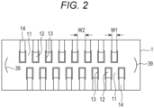
- Fig. 2 is a plan view illustrating an upper surface of the head chip illustrated in Fig. 1 .
- connection electrode 14 (voltage application electrode) drawn out from the metal layer 13 of each pressure chamber 12 is formed on the upper surface of the head chip 1.
- the connection electrode 14 can be formed by vapor deposition or sputtering.
- a nozzle plate 2 is joined to a lower surface of the head chip 1 using an adhesive.
- nozzles 21 are opened at positions corresponding to the outlets of the pressure chambers 12 of the head chip 1, respectively.
- the inlet and the outlet of each pressure chamber 12, and the nozzle 21 are linearly arranged.
- the nozzle plate 2 is preferably made of a material that can be ablated by laser light or a material that can be anisotropically etched.
- a resin sheet such as polyimide, polyethylene terephthalate, polyamide, or polysulfone, or silicon can be preferably used.
- polyimide which can withstand a high temperature for applying an ink repellent layer to a surface and on which precise nozzle processing with laser light can be performed.
- a wiring substrate 3 is joined to the upper surface of the head chip 1 on which the connection electrode 14 is formed using an adhesive.
- the wiring substrate 3 is a plate-shaped member for connecting wiring that applies a drive voltage from a drive circuit (not illustrated) to each metal layer 13 of the head chip 1.
- the wiring substrate 3 is made of a ceramic material such as non-polarized PZT, AlN-BN, or AlN, plastic or glass having low thermal expansion, a material obtained by depolarizing the same material as a substrate material of the piezoelectric body used in the head chip 1, or the like.
- the material of the wiring substrate 3 is preferably a material having a difference in thermal expansion coefficient within ⁇ 3 ppm with respect to unpolarized PZT in order to suppress distortion of the head chip 1 caused by a difference in linear expansion coefficient.
- the wiring substrate 3 is not limited to one plate-shaped wiring substrate, and may be a wiring substrate obtained by stacking a plurality of thin plate-shaped substrate materials to have a desired thickness.
- the wiring substrate 3 is formed in a rectangular shape larger than the upper surface of the head chip 1, and protrudes outward from the upper surface of the head chip 1 on both sides of a pressure chamber row direction (arrangement direction of pressure chambers 12, direction A in Fig. 1 ) and a direction orthogonal to the pressure chamber row direction (direction B in Fig. 1 ).
- a plurality of wiring electrodes (voltage application electrodes) 33 for connecting each metal layer 13 to an FPC (not illustrated) or the like is formed on a lower surface of the wiring substrate 3, which is a joining surface to the head chip 1, over a portion protruding outward.
- the same number of wiring electrodes 33 as the connection electrodes 14 formed on the upper surface of the head chip 1 are formed at the same pitch (W1 + W2).
- each wiring electrode 33 is electrically connected to each wire of the FPC or the like.
- Each wiring electrode 33 connected to each wire of the FPC or the like functions as an electrode for applying a drive voltage from a drive circuit (not illustrated) to the metal layer 13 in the pressure chamber 12 via the connection electrode 14.
- An opening 32 penetrating the wiring substrate 3 from a lower surface of the wiring substrate 3 to an upper surface thereof is formed in a substantially central portion of the wiring substrate 3.
- the opening 32 has a size that allows inlet-side openings of all the pressure chambers 12 facing the upper surface of the head chip 1 to be exposed to the upper surface side.
- Each wiring electrode 33 is formed from a peripheral edge of the opening 32 to an outer edge of the wiring substrate 3.
- a dummy electrode 36a that is positioned between the wiring electrodes 33 and is not involved in driving is formed on the lower surface of the wiring substrate 3.
- the dummy electrode 36a is formed such that a portion between the head chip 1 and the wiring substrate 3 is sealed with the adhesive.
- a positioning pattern 38 for positioning the head chip 1 is formed on the lower surface of the wiring substrate 3. When the head chip 1 and the wiring substrate 3 are joined to each other, the positioning pattern 38 is fitted to a positioning pattern 39 (see Fig. 2 ) formed on the upper surface of the head chip 1 to position the head chip 1 and the wiring substrate 3.
- the adhesive is applied to bonding surfaces of the head chip 1 and the wiring substrate 3 (an upper surface of the head chip 1 and a lower surface of the wiring substrate 3).
- each connection electrode 14 of the head chip 1 and each wiring electrodes 33 of the wiring substrate 3 are aligned so as to be electrically connected to each other and superimposed.
- the head chip 1 and the wiring substrate 3 are joined to each other.
- the head chip 1 and the nozzle plate 2 are also joined to each other by applying the adhesive to the bonding surfaces of the head chip 1 and the nozzle plate 2 (a lower surface of the head chip 1 and an upper surface of the nozzle plate 2), aligning and superimposing the head chip 1 and the nozzle plate 2, and heating and pressurizing the head chip 1 and the nozzle plate 2 at a predetermined temperature for a predetermined time to cure the adhesive.
- the amount of the adhesive applied to a member surface is not particularly limited, but a wet film thickness when the adhesive is applied is preferably 0.5 ⁇ m or more and 1000 ⁇ m or less.
- the wet film thickness when the adhesive is applied is preferably 1.0 ⁇ m or more and 25.0 ⁇ m or less.
- the wet film thickness is 0.5 ⁇ m or more, durability of joining between the members can be improved.
- the wet film thickness is 1000 ⁇ m or less, the amount of the adhesive is not excessive, and overflow of the adhesive and the like can be prevented.
- a constituent member such as a manifold other than the above-described members of the inkjet head is also joined to other members using the adhesive to constitute the inkjet head.
- the adhesion of the constituent members of the inkjet head includes, in addition to the above-described adhesion between the upper surface of the head chip 1 and the lower surface of the wiring substrate 3 and the above-described adhesion between the lower surface of the head chip 1 and the upper surface of the nozzle plate 2, adhesion between a lower end of a flexible substrate and the lower surface of the wiring substrate 3, adhesion between the wiring substrate 3 and a manifold (not illustrated), adhesion between the manifold and a filter (not illustrated), adhesion between a housing (not illustrated) and a cap receiving plate (not illustrated), and the like.
- the adhesive used in the present embodiment contains at least an epoxy resin as a main agent, a microencapsulated imidazole-based curing agent as a curing agent, and an alcohol that dissolves the microcapsules at a low temperature.
- an epoxy resin and an imidazole-based curing agent which is a chain polymerization type curing agent this adhesive can secure durability of a high adhesive force against ink, chemical resistance, that is, organic solvent durability (curability). High durability against ink is a preferable characteristic as an inkjet head.
- the epoxy resin is not cured unless the microcapsules are dissolved, and therefore a time for joining work can be secured before the epoxy resin is cured. It is a preferable characteristic as an inkjet head constituted by positioning and bonding a large number of members to spend a time in joining work before the epoxy resin is cured.
- this adhesive contains an alcohol that dissolves microcapsules at a low temperature
- curing at a high temperature such as 100°C or higher can be unnecessary in order to dissolve the microcapsules, and curing at a temperature 100°C or lower is performed.
- thermal stress in the inkjet head during assembly does not increase, and the constituent members are not damaged by high temperature. Therefore, long-term reliability can be secured.
- an epoxy resin applicable to the adhesive in the present embodiment either a monomer of a compound having an epoxy group or an oligomer thereof can be used. Specific examples thereof include a conventionally known aromatic epoxy resin, alicyclic epoxy resin, and aliphatic epoxy resin. Note that the epoxy resin means a monomer or an oligomer thereof. In the present embodiment, the epoxy resin preferably contains an aromatic epoxy resin in an amount of 70 to 99% by mass in the epoxy resin from a viewpoint of durability against ink. As the epoxy resin used in the adhesive of the present embodiment, one type of epoxy resin may be used, or many types thereof may be used in mixture.
- the aromatic epoxy resin is preferably a diglycidyl ether or polyglycidyl ether produced by a reaction between a polyhydric phenol having at least one aromatic nucleus or an alkylene oxide adduct thereof and epichlorohydrin.
- the aromatic epoxy resin contains a novolac type epoxy resin, and can further contain, for example, at least one of diglycidyl ether or polyglycidyl ether of bisphenol A or a polyalkylene oxide adduct thereof, a diglycidyl ether or polyglycidyl ether of hydrogenated bisphenol A or a polyalkylene oxide adduct thereof, and an epoxy resin derived from a bisphenol F type epoxy resin, a novolac, or a bisphenol.
- the bisphenol examples include a bisphenol A type epoxy resin and a bisphenol F type epoxy resin.
- examples of the polyalkylene oxide include polyethylene oxide and polypropylene oxide.
- a bisphenol F type epoxy resin is preferably contained as a main agent.
- the novolac type epoxy examples include a phenol novolac type epoxy resin and a cresol novolac type epoxy resin.
- the novolac type epoxy resin is a compound having a plurality of glycidyl groups in one molecule generated by a reaction between a hydroxy group of a novolac resin and epichlorohydrin.
- the number of epoxy groups in one molecule has a distribution, and an average value thereof varies depending on a synthesis condition, but the average number of epoxy groups in one molecule is preferably 3 or more.
- Examples of a commercially available product of the novolac type epoxy resin include jER 152 (phenol novolac epoxy resin, manufactured by Japan Epoxy Resin Co., Ltd.), jER 154 (phenol novolac epoxy resin, manufactured by Japan Epoxy Resin Co., Ltd.), and EPICLON N-660 (cresol novolac epoxy resin, manufactured by DIC Corporation).
- a polyfunctional epoxy resin is a tri- or higher functional epoxy resin excluding novolac epoxy.
- Specific examples of the polyfunctional epoxy resin include triglycidyl-p-aminophenol (92.3) (referred to as TGAP), tetraglycidyl diaminodiphenylmethane (105.5), triglycidyl isocyanurate (99), triglycidyl urazole (89.7), triglycidyl aminocresol (97), and tetraglycidyl-1,3-diaminomethylcyclohexane (91.5).
- TGAP is preferably used.
- an epoxy resin containing a novolac type epoxy resin further contains an alicyclic epoxy resin
- high photosensitivity can be obtained.
- the alicyclic epoxy resin include a cyclohexene oxide- or cyclopentene oxide-containing compound obtained by epoxidizing a compound having at least one cyclohexene or cycloalkane ring such as a cyclopentene ring with an appropriate oxidizing agent such as hydrogen peroxide or peracid.
- Specific examples of the alicyclic epoxy resin include (3,4-epoxycyclohexyl) methyl-3',4'-epoxycyclohexylcarboxylate and bis-(2,3-epoxycyclopentyl) ether.
- an imidazole-based curing agent that is a thermal anionic polymerization initiator for polyaddition or thermal polymerization of an epoxy monomer is used.
- imidazole-based curing agent examples include 1-methylimidazole, 1-benzyl-2-methylimidazole, 1,2-dimethylimidazole, 1-isobutyl-2-methylimidazole, 1-methyl-2-ethylimidazole, 1-ethylimidazole, 1-cyanoethyl-2-ethyl-4-methylimidazole, 1-cyanoethyl-2-methylimidazole, 1-(2-hydroxy-3-phenoxypropyl)-2-ethyl-4-methylimidazole, 1-(2-hydroxy-3-phenoxypropyl)-2-methylimidazole, 2-methylimidazole, and 2-ethyl-4-methylimidazole.
- the curing agent is microencapsulated and added to the adhesive.
- an imidazole-based curing agent for example, HXA-3932 (obtained by microencapsulating an imidazole-based thermal polymerization initiator with MMA, and having an average particle size of 2 ⁇ m, manufactured by Asahi Kasei Chemicals Corporation), HX-3741 (obtained by microencapsulating an imidazole-based thermal polymerization initiator with MMA, and having an average particle size of 5 ⁇ m, manufactured by Asahi Kasei Chemicals Corporation), HX-3722 (obtained by microencapsulating an imidazole-based thermal polymerization initiator with MMA, and having an average particle size of 2 ⁇ m, manufactured by Asahi Kasei Chemicals Corporation), and the like are commercially available.
- microcapsules of an imidazole-based curing agent are added in an amount of preferably 1 to 100 parts by mass, more preferably 10 to 80 parts by mass with respect to 100 parts by mass of the epoxy resin.
- the microcapsules are dissolved when the epoxy resin is cured. However, the microcapsules are not completely dissolved, and some of the microcapsules are dissolved to leave a residue (shell). The residue after the microcapsules are dissolved is diffused in the epoxy resin, and serves as a soft segment to improve heat cycle resistance after the epoxy resin is cured. Note that presence or absence and a diffusion state of the residue of the microcapsules in the epoxy resin can be confirmed with an electron microscope.
- Presence or absence and a diffusion state of the residue of the microcapsules in the epoxy resin can also be confirmed by organic substance mapping analysis by FT-IR (by performing mapping analysis on an organic substance in a minute region, the organic substance can be identified, and a present region can be specified), imaging by TOF-SIMS (time-of-flight secondary ion mass spectrometry) (mass imaging analysis can be performed on samples having various sizes from ⁇ m to cm order), and the like.
- microcapsules there are various types of microcapsules and production methods for the microcapsules.
- shell microcapsules using an epoxy resin and isocyanate are preferable from a viewpoint of dispersing the microcapsules in an epoxy resin as a main agent.
- the isocyanate to be a precursor of the microcapsules only needs to be, for example, a compound having two or more isocyanate groups in a molecule thereof as a polyvalent isocyanate, and specific examples thereof include a diisocyanate such as m-phenylene diisocyanate, p-phenylene diisocyanate, 2,4-tolylene diisocyanate, 2,6-tolylene diisocyanate, naphthalene-1,4-diisocyanate, diphenylmethane-4,4-diisocyanate, 3,3-dimethoxy-4,4-biphenyl diisocyanate, 3,3-dimethyldiphenylmethane-4,4-diisocyanate, xylylene-1,4-diisocyanate, 4,4-diphenylpropane diisocyanate, trimethylenediisocyanate, hexamethylene diisocyanate, propylene-1,2-d
- an isocyanate prepolymer represented by a polymethylene polyphenyl isocyanate such as an adduct of tolylene diisocyanate and trimethylolpropane, an adduct of xylylene diisocyanate and trimethylolpropane, or triphenyldimethylene triisocyanate from a viewpoint of film formability and mechanical strength when microcapsules are prepared.
- the adhesive may contain a silane coupling agent in order to improve durability of an adhesive force.
- silane coupling agent examples include ⁇ -(3,4-epoxycyclohexyl) ethyltrimethoxysilane, ⁇ -glycidoxypropyltrimethoxysilane, ⁇ -glycidoxypropylmethyldimethoxysilane, and ⁇ -glycidoxypropylmethyldiethoxysilane.
- the addition amount of the silane coupling agent is preferably 0.5 to 5 parts by mass with respect to 100 parts by mass of the epoxy resin.
- the addition amount is 0.5 parts by mass or more, durability of an adhesive force is excellent, and when the addition amount is 5 parts by mass or less, a viscosity increase during storage at room temperature is small, and a pot life can be extended.
- the alcohol examples include 4-methoxybenzyl alcohol (boiling point: 259°C), 2-phenylethanol (boiling point: 219°C), nonyl alcohol (boiling point: 214°C), benzyl alcohol (boiling point: 205°C), octyl alcohol (boiling point: 194°C), and hexanol (boiling point: 157°C) as high-boiling-point alcohols, and pentanol (boiling point: 137°C) and isopropanol (boiling point: 82.4°C) as low-boiling-point alcohols.
- benzyl alcohol is preferable.
- the alcohol include further include 4-methylbenzyl alcohol, 2-phenylethanol, 3,4-dimethoxybenzyl alcohol, 4-methoxybenzyl alcohol, nonyl alcohol, and piperonyl alcohol.
- the content of the alcohol is preferably 0.1 parts by mass or more and 10 parts by mass or less with respect to 100 parts by mass of the epoxy resin as a main agent. This is because when the content is less than 0.1 parts by mass, solvent resistance is poor, and when the content exceeds 10 parts by mass, the solvent resistance is poor or heat cycle resistance is poor.
- the microcapsules are dissolved at a temperature of, 100°C or lower, and therefore the epoxy resin can be cured at a low temperature.
- the alcohol acts as a medium for uniformly dispersing a residue of the microcapsules after the microcapsules are dissolved, and the residue of the microcapsules can be used as a soft segment.
- the epoxy resin cured with the imidazole-based curing agent has good solvent resistance, but is hard and brittle.
- the residue of the microcapsules serving as a soft segment is uniformly dispersed in the epoxy resin, toughness is thereby imparted to the entire epoxy resin, and the hard brittles property is relaxed.
- the epoxy resin is cured at a low temperature in a short time, acquires a strong property against thermal stress while maintaining good solvent resistance, and can largely improve long-term reliability of the inkjet head.
- the long-term reliability is temperature fluctuation resistance in a use environment, and can be confirmed by assembling composite materials having different linear expansions and performing a heat cycle (reliability) test.
- the alcohol is preferably a high-boiling-point alcohol.
- the high-boiling-point alcohol preferably has a boiling point of 150°C or higher.
- the alcohol also preferably has a benzene ring.
- An alcohol having a benzene ring can more preferably prevent volatilization thereof at a curing temperature of the epoxy resin, remains until the epoxy resin is completely cured, and therefore can favorably dissolve microcapsules made of, for example, urethane. Furthermore, the residue of the microcapsules can be more uniformly dispersed by the alcohol remaining until the epoxy resin is completely cured.
- An ink applicable when an image is formed using an inkjet printer including the inkjet head of the present embodiment is not particularly limited, and examples thereof include an aqueous ink, a non-aqueous ink, a wax ink, and an active curable ink.
- a dye ink in which a coloring material is a dye a pigment ink in which a coloring material is insoluble in a solvent constituting the ink and forms a dispersion system containing fine pigment particles, a dispersion ink formed of a dispersion of a polymer in which a coloring material is colored, or the like is used.
- an ink containing an organic solvent in an amount of 50% or more and 100% or less with respect to the total amount of solvents, and containing an organic solvent having a high solubility in a resin component and having a solubility parameter (SP value) of 16.0 or more and 21.0 or less with respect to the resin component in an amount of 30% by mass or more and 100% or less with respect to the total amount of organic solvents to image formation from a viewpoint of being able to sufficiently exhibit the excellent characteristics of the inkjet head of the present embodiment.
- SP value solubility parameter
- the ink includes a coloring material such as a dye or a pigment, an organic solvent (solvent) that dissolves the coloring material, and the like, and the types thereof are not particularly limited.
- the ink it is preferable to use an organic solvent having a high solubility in a resin, but even if an organic solvent having a high resin solubility is used, it is necessary to maintain the strength as the inkjet head.
- the inkjet printer is preferably suitable for an ink containing an organic solvent in an amount of 50% or more and 100% or less with respect to the total amount of solvents.
- An ink preferably contains a solvent having a solubility parameter (SP) value ((cal/cm) 1/2 ) of 9.5 to 15.0 and a dipole efficiency of 2.0 to 5.0 in an amount of 3% by weight or more with respect to the total amount of solvents from a viewpoint of fixability of a print image.
- SP solubility parameter
- the present embodiment has a characteristic that durability is not deteriorated against such an ink.
- the SP value (solubility parameter of organic solvent) is a value represented by a square root of molecular aggregation energy and is calculated by a Bicerano method.
- the "Bicerano method” is described in Prediction of Polymer Properties (Plastics Engineering, 65) written by Jozef Bicerano.
- the unit of the SP value is (MPa) 1/2 and the SP value refers to a value at 25°C.
- Examples of the organic solvent having an SP value defined in the present embodiment are also described in " Polymer Handbook", third edition (John Wily & Sons), co-edited by J. Brandup, and E. H. Immergu, 1989, VII/pp. 526 to 539 .
- the dipole efficiency is calculated by AM1 of MOPAC.
- organic solvent having an SP value of 16.0 (MPa) 1/2 or more and 21.0 (MPa) 1/2 or less will be described below, but the organic solvent is not limited to these exemplary compounds. Note that a numerical value in parentheses represents an SP value ((MPa) 1/2 ).
- coloring materials for forming yellow, magenta, cyan, black, blue, green, and red inks are preferably used.
- the ink in the present embodiment can contain various additives in addition to the organic solvent.
- compositions were mixed to prepare an adhesive.
- Microcapsules (microcapsule type thermal anionic polymerization initiator): 50 parts by mass
- the adhesive was cured at a curing temperature of 60°C to perform bonding, thus preparing an inkjet head.
- the above adhesive was cured at a curing temperature of 60°C to prepare pellets.
- Example 1-1 An inkjet head and pellets were prepared in a similar manner to Example 1-1 except that the curing temperature of the adhesive was 80°C.
- Example 1-1 An inkjet head and pellets were prepared in a similar manner to Example 1-1 except that the curing temperature of the adhesive was 100°C.
- Example 1-2 An inkjet head and pellets were prepared in a similar manner to Example 1-2 except that hexanol (boiling point: 157°C), which is a high-boiling-point alcohol (2), was used as the alcohol.
- hexanol boiling point: 157°C
- Example 1-2 An inkjet head and pellets were prepared in a similar manner to Example 1-2 except that pentanol (boiling point: 137°C), which is a low-boiling-point alcohol (1), was used as the alcohol.
- pentanol boiling point: 137°C
- Example 1-2 An inkjet head and pellets were prepared in a similar manner to Example 1-2 except that isopropanol (boiling point: 82.4°C), which is a low-boiling-point alcohol (2), was used as the alcohol.
- Example 1-1 An inkjet head and pellets were prepared in a similar manner to Example 1-1 except that no alcohol was added.
- Example 1-2 An inkjet head and pellets were prepared in a similar manner to Example 1-2 except that no alcohol was added.
- Example 1-3 An inkjet head and pellets were prepared in a similar manner to Example 1-3 except that no alcohol was added.
- Example 1-1 An inkjet head and pellets were prepared in a similar manner to Example 1-1 except that the curing agent was not microencapsulated.
- Example 1-2 An inkjet head and pellets were prepared in a similar manner to Example 1-2 except that the curing agent was not microencapsulated.
- Example 1-3 An inkjet head and pellets were prepared in a similar manner to Example 1-3 except that the curing agent was not microencapsulated.
- Example 1-1 An inkjet head and pellets were prepared in a similar manner to Example 1-1 except that no alcohol was added and the curing agent was not microencapsulated.
- Example 1-2 An inkjet head and pellets were prepared in a similar manner to Example 1-2 except that no alcohol was added and the curing agent was not microencapsulated.
- Example 1-3 An inkjet head and pellets were prepared in a similar manner to Example 1-3 except that no alcohol was added and the curing agent was not microencapsulated.
- Example 1 Constituent element Alcohol boiling point Curing temperature Organic solvent durability (curability) test Heat cycle (reliability) test Throughput (thickening rate) measurement Main agent Curing agent (Capsule-dissolving solvent)
- Example 1-1 High-boiling-point alcohol (1) Benzyl alcohol 205°C 60°C ⁇ ⁇ ⁇ Example 1-2 High-boiling-point alcohol (1) Benzyl alcohol 205°C 80°C ⁇ ⁇ ⁇ Example 1-3 High-boiling-point alcohol (1) Benzyl alcohol 205°C 100°C ⁇ ⁇ ⁇ Example 2 High-boiling-point alcohol (2) Hexanol 157°C 80°C ⁇ ⁇ ⁇ Example 3 Microencapsulated imidazole Low-boiling-point alcohol (1) Pentanol 137°C 80°C ⁇ ⁇ ⁇ Example 4 Low-boiling-point alcohol (2) Isopropanol 82.4°C 80°C ⁇ ⁇ ⁇ Compar
- the adhesive of Example 1-1 contains the microencapsulated curing agent and the alcohol that dissolves the microcapsules at a low temperature. Therefore, the adhesive of Example 1-1 can be sufficiently cured even at a low temperature of 60°C as compared with the adhesive of Comparative Example 1-1, thermal stress does not increase in the inkjet head during assembly, and the constituent members are not damaged by a high temperature. Therefore, long-term reliability can be secured.
- Examples 1-1, 1-2, 1-3, 2, 3, and 4 had " ⁇ (acceptable) " to” ⁇ (best) ".
- the adhesives of Examples 1-1, 1-2, 1-3, 2, 3, and 4 each contain the microencapsulated curing agent and the alcohol that dissolves the microcapsules at a low temperature. Therefore, it has been confirmed that the adhesives of Examples 1-1, 1-2, 1-3, 2, 3, and 4 can be cured at a low temperature of 100°C or lower, even when members made of many types of materials are joined to each other, the members are not deformed after the adhesives are cured due to a difference in linear expansion coefficient between the members, heat cycle resistance is high, and peeling does not occur in a joint.
- a high-boiling-point alcohol is preferable as the alcohol, and a difference between the boiling point of the alcohol and the curing temperature is preferably 120°C or more. This is considered to be because by interposing the high-boiling-point alcohol in the polymer structure of the epoxy resin, the cured epoxy resin is softened, stress of a bonding portion between the members is relaxed, and heat cycle resistance (reliability) and stability of ink ejection are improved.
- the adhesive of Example 1-1 contains the microencapsulated curing agent and the alcohol that dissolves the microcapsules at a low temperature. Therefore, unlike Comparative Examples 1-1, 2-1, and 3-1, it has been confirmed that the adhesive of Example 1-1 can be sufficiently cured even at a low temperature of 60°C, and the viscosity increase rate of the epoxy resin is reduced to secure a time for joining work before the epoxy resin is cured. It is a preferable characteristic as an inkjet head constituted by positioning and bonding a large number of members to spend a time in joining work before the epoxy resin is cured.
Landscapes
- Engineering & Computer Science (AREA)
- Manufacturing & Machinery (AREA)
- Chemical & Material Sciences (AREA)
- Organic Chemistry (AREA)
- Health & Medical Sciences (AREA)
- Chemical Kinetics & Catalysis (AREA)
- Medicinal Chemistry (AREA)
- Polymers & Plastics (AREA)
- Physics & Mathematics (AREA)
- Optics & Photonics (AREA)
- Particle Formation And Scattering Control In Inkjet Printers (AREA)
- Adhesives Or Adhesive Processes (AREA)
Applications Claiming Priority (1)
| Application Number | Priority Date | Filing Date | Title |
|---|---|---|---|
| PCT/JP2019/042575 WO2021084649A1 (ja) | 2019-10-30 | 2019-10-30 | インクジェットヘッド及びインクジェットヘッドの製造方法 |
Publications (3)
| Publication Number | Publication Date |
|---|---|
| EP4052913A1 EP4052913A1 (en) | 2022-09-07 |
| EP4052913A4 EP4052913A4 (en) | 2022-10-19 |
| EP4052913B1 true EP4052913B1 (en) | 2025-01-08 |
Family
ID=75714927
Family Applications (1)
| Application Number | Title | Priority Date | Filing Date |
|---|---|---|---|
| EP19950822.7A Active EP4052913B1 (en) | 2019-10-30 | 2019-10-30 | Inkjet head and production method for inkjet head |
Country Status (5)
| Country | Link |
|---|---|
| US (1) | US11919308B2 (https=) |
| EP (1) | EP4052913B1 (https=) |
| JP (1) | JP7276490B2 (https=) |
| CN (1) | CN114641396B (https=) |
| WO (1) | WO2021084649A1 (https=) |
Families Citing this family (2)
| Publication number | Priority date | Publication date | Assignee | Title |
|---|---|---|---|---|
| JP7840744B2 (ja) * | 2022-03-17 | 2026-04-06 | 旭化成株式会社 | 一液性エポキシ樹脂組成物用マスターバッチ型硬化剤、及びエポキシ樹脂組成物 |
| JPWO2024075602A1 (https=) * | 2022-10-07 | 2024-04-11 |
Family Cites Families (13)
| Publication number | Priority date | Publication date | Assignee | Title |
|---|---|---|---|---|
| JPS51139478A (en) | 1975-05-27 | 1976-12-01 | Nitto Electric Ind Co | Box components for assembling |
| JPH093164A (ja) | 1995-06-15 | 1997-01-07 | Nitto Denko Corp | マイクロカプセル型硬化剤または硬化促進剤、およびそれを含有してなるエポキシ樹脂組成物 |
| JP2000129238A (ja) | 1998-10-26 | 2000-05-09 | Nitto Denko Corp | シート状接着剤組成物およびそれを用いた電子部品装置ならびにそのリペアー方法 |
| JP2004277458A (ja) * | 2003-03-12 | 2004-10-07 | Nagase Chemtex Corp | 1液型エポキシ樹脂組成物およびそれを用いた1液型エポキシ樹脂系接着剤 |
| JP4237088B2 (ja) * | 2003-07-24 | 2009-03-11 | 東京応化工業株式会社 | 感光性樹脂組成物および該組成物を用いたパターン形成方法 |
| KR100717028B1 (ko) * | 2005-09-13 | 2007-05-10 | 삼성전자주식회사 | 전도성 에폭시 수지를 구비한 잉크젯 프린터 헤드 |
| JP2007269959A (ja) | 2006-03-31 | 2007-10-18 | Nippon Handa Kk | 導電性接着剤、電子装置およびその製造方法 |
| US7923488B2 (en) | 2006-10-16 | 2011-04-12 | Trillion Science, Inc. | Epoxy compositions |
| JP5279117B2 (ja) | 2008-05-28 | 2013-09-04 | コニカミノルタ株式会社 | インクジェットヘッド |
| JP2011032387A (ja) | 2009-08-03 | 2011-02-17 | Toppan Forms Co Ltd | 硬化性組成物 |
| JP2011109005A (ja) * | 2009-11-20 | 2011-06-02 | Sumitomo Electric Ind Ltd | 配線板接続体の製造方法、および配線板 |
| JP5754378B2 (ja) | 2010-01-22 | 2015-07-29 | コニカミノルタ株式会社 | インクジェットヘッドの製造方法 |
| JP6525630B2 (ja) * | 2015-02-18 | 2019-06-05 | キヤノン株式会社 | 液体吐出ヘッドおよびその製造方法 |
-
2019
- 2019-10-30 CN CN201980101917.1A patent/CN114641396B/zh active Active
- 2019-10-30 EP EP19950822.7A patent/EP4052913B1/en active Active
- 2019-10-30 WO PCT/JP2019/042575 patent/WO2021084649A1/ja not_active Ceased
- 2019-10-30 US US17/771,315 patent/US11919308B2/en active Active
- 2019-10-30 JP JP2021553958A patent/JP7276490B2/ja active Active
Also Published As
| Publication number | Publication date |
|---|---|
| EP4052913A1 (en) | 2022-09-07 |
| JPWO2021084649A1 (https=) | 2021-05-06 |
| JP7276490B2 (ja) | 2023-05-18 |
| CN114641396B (zh) | 2024-03-08 |
| US20220402269A1 (en) | 2022-12-22 |
| CN114641396A (zh) | 2022-06-17 |
| WO2021084649A1 (ja) | 2021-05-06 |
| EP4052913A4 (en) | 2022-10-19 |
| US11919308B2 (en) | 2024-03-05 |
Similar Documents
| Publication | Publication Date | Title |
|---|---|---|
| US7922860B2 (en) | Manufacturing inkjet head by adhering with epoxy resins and alkyl imidazole | |
| US5637156A (en) | Resin Composition and an electronic device using the same | |
| EP4052913B1 (en) | Inkjet head and production method for inkjet head | |
| CN102259496B (zh) | 液体喷射头及其制备方法 | |
| JP2014078574A (ja) | 電磁波シールド性カバーレイフィルム、フレキシブルプリント配線板の製造方法、及びフレキシブルプリント配線板 | |
| CN110121535B (zh) | 水分散物及其制造方法、以及图像形成方法 | |
| EP3210781B1 (en) | Ink discharging apparatus and ink discharging method | |
| US20140292930A1 (en) | Processing and application of liquid epoxy adhesive for printhead structures interstitial bonding in high density piezo printheads fabrication | |
| EP4470780B1 (en) | Fluid ejection head, method for producing fluid ejection head, fluid ejection assembly, and fluid ejection device | |
| EP2263880B1 (en) | Liquid discharge head and method for manufacturing the same | |
| US9004648B2 (en) | Inkjet printheads containing epoxy adhesives and methods for fabrication thereof | |
| EP0749043B1 (en) | Process for production of ink jet head | |
| JP5070963B2 (ja) | 液晶表示装置用スペーサの形成方法、スペーサ形成用インク、並びに液晶表示装置及びその製造方法 | |
| EP2527151B1 (en) | Method for manufacturing inkjet head | |
| US7438394B2 (en) | Inkjet head and method for making the same | |
| JP4987291B2 (ja) | インクジェットヘッド及びその製造方法 | |
| CN1213156A (zh) | 柔性电路及其制备方法 | |
| US7557230B2 (en) | Latent curing agent | |
| EP4681924A1 (en) | Inkjet head and inkjet recording device | |
| CN105015167B (zh) | 一种用于形成用于水性喷墨的喷墨打印头的方法 | |
| JP5928785B2 (ja) | 液晶表示装置用スペーサ形成インク及び、液晶表示装置、その製造方法 | |
| JP2025001808A (ja) | 液体噴射ヘッド及び液体噴射装置 | |
| JP2024122282A (ja) | シールドパッケージとその製造方法 | |
| JP2013029741A (ja) | 液晶表示装置及びその製造方法 |
Legal Events
| Date | Code | Title | Description |
|---|---|---|---|
| STAA | Information on the status of an ep patent application or granted ep patent |
Free format text: STATUS: THE INTERNATIONAL PUBLICATION HAS BEEN MADE |
|
| PUAI | Public reference made under article 153(3) epc to a published international application that has entered the european phase |
Free format text: ORIGINAL CODE: 0009012 |
|
| STAA | Information on the status of an ep patent application or granted ep patent |
Free format text: STATUS: REQUEST FOR EXAMINATION WAS MADE |
|
| 17P | Request for examination filed |
Effective date: 20220523 |
|
| AK | Designated contracting states |
Kind code of ref document: A1 Designated state(s): AL AT BE BG CH CY CZ DE DK EE ES FI FR GB GR HR HU IE IS IT LI LT LU LV MC MK MT NL NO PL PT RO RS SE SI SK SM TR |
|
| A4 | Supplementary search report drawn up and despatched |
Effective date: 20220921 |
|
| RIC1 | Information provided on ipc code assigned before grant |
Ipc: C08G 59/24 20060101ALI20220914BHEP Ipc: C09J 163/00 20060101ALI20220914BHEP Ipc: C08G 59/68 20060101ALI20220914BHEP Ipc: C08G 59/18 20060101ALI20220914BHEP Ipc: B41J 2/14 20060101ALI20220914BHEP Ipc: B41J 2/16 20060101AFI20220914BHEP |
|
| DAV | Request for validation of the european patent (deleted) | ||
| DAX | Request for extension of the european patent (deleted) | ||
| P01 | Opt-out of the competence of the unified patent court (upc) registered |
Effective date: 20230510 |
|
| GRAP | Despatch of communication of intention to grant a patent |
Free format text: ORIGINAL CODE: EPIDOSNIGR1 |
|
| STAA | Information on the status of an ep patent application or granted ep patent |
Free format text: STATUS: GRANT OF PATENT IS INTENDED |
|
| INTG | Intention to grant announced |
Effective date: 20240805 |
|
| GRAS | Grant fee paid |
Free format text: ORIGINAL CODE: EPIDOSNIGR3 |
|
| GRAA | (expected) grant |
Free format text: ORIGINAL CODE: 0009210 |
|
| STAA | Information on the status of an ep patent application or granted ep patent |
Free format text: STATUS: THE PATENT HAS BEEN GRANTED |
|
| AK | Designated contracting states |
Kind code of ref document: B1 Designated state(s): AL AT BE BG CH CY CZ DE DK EE ES FI FR GB GR HR HU IE IS IT LI LT LU LV MC MK MT NL NO PL PT RO RS SE SI SK SM TR |
|
| REG | Reference to a national code |
Ref country code: GB Ref legal event code: FG4D |
|
| REG | Reference to a national code |
Ref country code: CH Ref legal event code: EP |
|
| REG | Reference to a national code |
Ref country code: DE Ref legal event code: R096 Ref document number: 602019064779 Country of ref document: DE |
|
| REG | Reference to a national code |
Ref country code: IE Ref legal event code: FG4D |
|
| REG | Reference to a national code |
Ref country code: LT Ref legal event code: MG9D |
|
| REG | Reference to a national code |
Ref country code: NL Ref legal event code: MP Effective date: 20250108 |
|
| REG | Reference to a national code |
Ref country code: AT Ref legal event code: MK05 Ref document number: 1758093 Country of ref document: AT Kind code of ref document: T Effective date: 20250108 |
|
| PG25 | Lapsed in a contracting state [announced via postgrant information from national office to epo] |
Ref country code: NL Free format text: LAPSE BECAUSE OF FAILURE TO SUBMIT A TRANSLATION OF THE DESCRIPTION OR TO PAY THE FEE WITHIN THE PRESCRIBED TIME-LIMIT Effective date: 20250108 |
|
| PG25 | Lapsed in a contracting state [announced via postgrant information from national office to epo] |
Ref country code: RS Free format text: LAPSE BECAUSE OF FAILURE TO SUBMIT A TRANSLATION OF THE DESCRIPTION OR TO PAY THE FEE WITHIN THE PRESCRIBED TIME-LIMIT Effective date: 20250408 |
|
| PG25 | Lapsed in a contracting state [announced via postgrant information from national office to epo] |
Ref country code: FI Free format text: LAPSE BECAUSE OF FAILURE TO SUBMIT A TRANSLATION OF THE DESCRIPTION OR TO PAY THE FEE WITHIN THE PRESCRIBED TIME-LIMIT Effective date: 20250108 |
|
| PG25 | Lapsed in a contracting state [announced via postgrant information from national office to epo] |
Ref country code: PL Free format text: LAPSE BECAUSE OF FAILURE TO SUBMIT A TRANSLATION OF THE DESCRIPTION OR TO PAY THE FEE WITHIN THE PRESCRIBED TIME-LIMIT Effective date: 20250108 |
|
| PG25 | Lapsed in a contracting state [announced via postgrant information from national office to epo] |
Ref country code: ES Free format text: LAPSE BECAUSE OF FAILURE TO SUBMIT A TRANSLATION OF THE DESCRIPTION OR TO PAY THE FEE WITHIN THE PRESCRIBED TIME-LIMIT Effective date: 20250108 |
|
| PG25 | Lapsed in a contracting state [announced via postgrant information from national office to epo] |
Ref country code: IS Free format text: LAPSE BECAUSE OF FAILURE TO SUBMIT A TRANSLATION OF THE DESCRIPTION OR TO PAY THE FEE WITHIN THE PRESCRIBED TIME-LIMIT Effective date: 20250508 Ref country code: NO Free format text: LAPSE BECAUSE OF FAILURE TO SUBMIT A TRANSLATION OF THE DESCRIPTION OR TO PAY THE FEE WITHIN THE PRESCRIBED TIME-LIMIT Effective date: 20250408 |
|
| PG25 | Lapsed in a contracting state [announced via postgrant information from national office to epo] |
Ref country code: HR Free format text: LAPSE BECAUSE OF FAILURE TO SUBMIT A TRANSLATION OF THE DESCRIPTION OR TO PAY THE FEE WITHIN THE PRESCRIBED TIME-LIMIT Effective date: 20250108 |
|
| PG25 | Lapsed in a contracting state [announced via postgrant information from national office to epo] |
Ref country code: LV Free format text: LAPSE BECAUSE OF FAILURE TO SUBMIT A TRANSLATION OF THE DESCRIPTION OR TO PAY THE FEE WITHIN THE PRESCRIBED TIME-LIMIT Effective date: 20250108 Ref country code: PT Free format text: LAPSE BECAUSE OF FAILURE TO SUBMIT A TRANSLATION OF THE DESCRIPTION OR TO PAY THE FEE WITHIN THE PRESCRIBED TIME-LIMIT Effective date: 20250508 |
|
| PG25 | Lapsed in a contracting state [announced via postgrant information from national office to epo] |
Ref country code: BG Free format text: LAPSE BECAUSE OF FAILURE TO SUBMIT A TRANSLATION OF THE DESCRIPTION OR TO PAY THE FEE WITHIN THE PRESCRIBED TIME-LIMIT Effective date: 20250108 Ref country code: GR Free format text: LAPSE BECAUSE OF FAILURE TO SUBMIT A TRANSLATION OF THE DESCRIPTION OR TO PAY THE FEE WITHIN THE PRESCRIBED TIME-LIMIT Effective date: 20250409 |
|
| PG25 | Lapsed in a contracting state [announced via postgrant information from national office to epo] |
Ref country code: AT Free format text: LAPSE BECAUSE OF FAILURE TO SUBMIT A TRANSLATION OF THE DESCRIPTION OR TO PAY THE FEE WITHIN THE PRESCRIBED TIME-LIMIT Effective date: 20250108 |
|
| PG25 | Lapsed in a contracting state [announced via postgrant information from national office to epo] |
Ref country code: SE Free format text: LAPSE BECAUSE OF FAILURE TO SUBMIT A TRANSLATION OF THE DESCRIPTION OR TO PAY THE FEE WITHIN THE PRESCRIBED TIME-LIMIT Effective date: 20250108 |
|
| PG25 | Lapsed in a contracting state [announced via postgrant information from national office to epo] |
Ref country code: SM Free format text: LAPSE BECAUSE OF FAILURE TO SUBMIT A TRANSLATION OF THE DESCRIPTION OR TO PAY THE FEE WITHIN THE PRESCRIBED TIME-LIMIT Effective date: 20250108 |
|
| REG | Reference to a national code |
Ref country code: DE Ref legal event code: R097 Ref document number: 602019064779 Country of ref document: DE |
|
| PG25 | Lapsed in a contracting state [announced via postgrant information from national office to epo] |
Ref country code: DK Free format text: LAPSE BECAUSE OF FAILURE TO SUBMIT A TRANSLATION OF THE DESCRIPTION OR TO PAY THE FEE WITHIN THE PRESCRIBED TIME-LIMIT Effective date: 20250108 |
|
| PGFP | Annual fee paid to national office [announced via postgrant information from national office to epo] |
Ref country code: GB Payment date: 20250911 Year of fee payment: 7 |
|
| PGFP | Annual fee paid to national office [announced via postgrant information from national office to epo] |
Ref country code: FR Payment date: 20250908 Year of fee payment: 7 |
|
| PG25 | Lapsed in a contracting state [announced via postgrant information from national office to epo] |
Ref country code: CZ Free format text: LAPSE BECAUSE OF FAILURE TO SUBMIT A TRANSLATION OF THE DESCRIPTION OR TO PAY THE FEE WITHIN THE PRESCRIBED TIME-LIMIT Effective date: 20250108 Ref country code: EE Free format text: LAPSE BECAUSE OF FAILURE TO SUBMIT A TRANSLATION OF THE DESCRIPTION OR TO PAY THE FEE WITHIN THE PRESCRIBED TIME-LIMIT Effective date: 20250108 |
|
| PG25 | Lapsed in a contracting state [announced via postgrant information from national office to epo] |
Ref country code: RO Free format text: LAPSE BECAUSE OF FAILURE TO SUBMIT A TRANSLATION OF THE DESCRIPTION OR TO PAY THE FEE WITHIN THE PRESCRIBED TIME-LIMIT Effective date: 20250108 |
|
| PG25 | Lapsed in a contracting state [announced via postgrant information from national office to epo] |
Ref country code: SK Free format text: LAPSE BECAUSE OF FAILURE TO SUBMIT A TRANSLATION OF THE DESCRIPTION OR TO PAY THE FEE WITHIN THE PRESCRIBED TIME-LIMIT Effective date: 20250108 |
|
| PLBE | No opposition filed within time limit |
Free format text: ORIGINAL CODE: 0009261 |
|
| STAA | Information on the status of an ep patent application or granted ep patent |
Free format text: STATUS: NO OPPOSITION FILED WITHIN TIME LIMIT |
|
| 26N | No opposition filed |
Effective date: 20251009 |
|
| PGFP | Annual fee paid to national office [announced via postgrant information from national office to epo] |
Ref country code: DE Payment date: 20250902 Year of fee payment: 7 |
|
| PG25 | Lapsed in a contracting state [announced via postgrant information from national office to epo] |
Ref country code: IT Free format text: LAPSE BECAUSE OF FAILURE TO SUBMIT A TRANSLATION OF THE DESCRIPTION OR TO PAY THE FEE WITHIN THE PRESCRIBED TIME-LIMIT Effective date: 20250108 |