WO2021079571A1 - ガリウム前駆体の製造方法およびこれを用いた積層体の製造方法 - Google Patents
ガリウム前駆体の製造方法およびこれを用いた積層体の製造方法 Download PDFInfo
- Publication number
- WO2021079571A1 WO2021079571A1 PCT/JP2020/027420 JP2020027420W WO2021079571A1 WO 2021079571 A1 WO2021079571 A1 WO 2021079571A1 JP 2020027420 W JP2020027420 W JP 2020027420W WO 2021079571 A1 WO2021079571 A1 WO 2021079571A1
- Authority
- WO
- WIPO (PCT)
- Prior art keywords
- gallium
- producing
- precursor
- solvent
- gallium precursor
- Prior art date
Links
- 229910052733 gallium Inorganic materials 0.000 title claims abstract description 124
- GYHNNYVSQQEPJS-UHFFFAOYSA-N Gallium Chemical compound [Ga] GYHNNYVSQQEPJS-UHFFFAOYSA-N 0.000 title claims abstract description 123
- 239000002243 precursor Substances 0.000 title claims abstract description 83
- 238000004519 manufacturing process Methods 0.000 title claims abstract description 38
- 239000002904 solvent Substances 0.000 claims abstract description 26
- 238000000034 method Methods 0.000 claims abstract description 19
- 239000002253 acid Substances 0.000 claims abstract description 14
- 239000003513 alkali Substances 0.000 claims abstract description 10
- 238000007670 refining Methods 0.000 claims abstract description 7
- 239000007864 aqueous solution Substances 0.000 claims abstract description 6
- 239000000243 solution Substances 0.000 claims description 38
- 239000000758 substrate Substances 0.000 claims description 31
- 239000012159 carrier gas Substances 0.000 claims description 12
- XLYOFNOQVPJJNP-UHFFFAOYSA-N water Substances O XLYOFNOQVPJJNP-UHFFFAOYSA-N 0.000 claims description 10
- 238000010438 heat treatment Methods 0.000 claims description 8
- QGZKDVFQNNGYKY-UHFFFAOYSA-N Ammonia Chemical compound N QGZKDVFQNNGYKY-UHFFFAOYSA-N 0.000 claims description 6
- 238000007865 diluting Methods 0.000 claims description 4
- 229910021529 ammonia Inorganic materials 0.000 claims description 3
- 229910000039 hydrogen halide Inorganic materials 0.000 claims description 2
- 239000012433 hydrogen halide Substances 0.000 claims description 2
- 239000010408 film Substances 0.000 description 38
- 239000003595 mist Substances 0.000 description 12
- VEXZGXHMUGYJMC-UHFFFAOYSA-N Hydrochloric acid Chemical compound Cl VEXZGXHMUGYJMC-UHFFFAOYSA-N 0.000 description 9
- 239000007789 gas Substances 0.000 description 9
- 239000002994 raw material Substances 0.000 description 9
- 239000012535 impurity Substances 0.000 description 8
- 239000000203 mixture Substances 0.000 description 7
- IJGRMHOSHXDMSA-UHFFFAOYSA-N Atomic nitrogen Chemical compound N#N IJGRMHOSHXDMSA-UHFFFAOYSA-N 0.000 description 6
- 230000000052 comparative effect Effects 0.000 description 6
- 239000000446 fuel Substances 0.000 description 6
- XMBWDFGMSWQBCA-UHFFFAOYSA-N hydrogen iodide Chemical compound I XMBWDFGMSWQBCA-UHFFFAOYSA-N 0.000 description 6
- 229910052594 sapphire Inorganic materials 0.000 description 6
- 239000010980 sapphire Substances 0.000 description 6
- OKTJSMMVPCPJKN-UHFFFAOYSA-N Carbon Chemical compound [C] OKTJSMMVPCPJKN-UHFFFAOYSA-N 0.000 description 5
- 229910052799 carbon Inorganic materials 0.000 description 5
- 239000013078 crystal Substances 0.000 description 5
- 238000004090 dissolution Methods 0.000 description 5
- -1 gallium halide Chemical class 0.000 description 5
- 239000010453 quartz Substances 0.000 description 5
- VYPSYNLAJGMNEJ-UHFFFAOYSA-N silicon dioxide Inorganic materials O=[Si]=O VYPSYNLAJGMNEJ-UHFFFAOYSA-N 0.000 description 5
- 229910005191 Ga 2 O 3 Inorganic materials 0.000 description 4
- 229910052782 aluminium Inorganic materials 0.000 description 4
- XAGFODPZIPBFFR-UHFFFAOYSA-N aluminium Chemical compound [Al] XAGFODPZIPBFFR-UHFFFAOYSA-N 0.000 description 4
- AJNVQOSZGJRYEI-UHFFFAOYSA-N digallium;oxygen(2-) Chemical compound [O-2].[O-2].[O-2].[Ga+3].[Ga+3] AJNVQOSZGJRYEI-UHFFFAOYSA-N 0.000 description 4
- 239000010419 fine particle Substances 0.000 description 4
- 229910001195 gallium oxide Inorganic materials 0.000 description 4
- XUIMIQQOPSSXEZ-UHFFFAOYSA-N Silicon Chemical compound [Si] XUIMIQQOPSSXEZ-UHFFFAOYSA-N 0.000 description 3
- 230000015572 biosynthetic process Effects 0.000 description 3
- 239000010431 corundum Substances 0.000 description 3
- 229910052593 corundum Inorganic materials 0.000 description 3
- 229910000043 hydrogen iodide Inorganic materials 0.000 description 3
- 229940071870 hydroiodic acid Drugs 0.000 description 3
- 229910052751 metal Inorganic materials 0.000 description 3
- 239000002184 metal Substances 0.000 description 3
- 150000002739 metals Chemical class 0.000 description 3
- 229910052757 nitrogen Inorganic materials 0.000 description 3
- 229910052710 silicon Inorganic materials 0.000 description 3
- 239000010703 silicon Substances 0.000 description 3
- 229910052718 tin Inorganic materials 0.000 description 3
- ZVYYAYJIGYODSD-LNTINUHCSA-K (z)-4-bis[[(z)-4-oxopent-2-en-2-yl]oxy]gallanyloxypent-3-en-2-one Chemical compound [Ga+3].C\C([O-])=C\C(C)=O.C\C([O-])=C\C(C)=O.C\C([O-])=C\C(C)=O ZVYYAYJIGYODSD-LNTINUHCSA-K 0.000 description 2
- BMYNFMYTOJXKLE-UHFFFAOYSA-N 3-azaniumyl-2-hydroxypropanoate Chemical compound NCC(O)C(O)=O BMYNFMYTOJXKLE-UHFFFAOYSA-N 0.000 description 2
- 229910018072 Al 2 O 3 Inorganic materials 0.000 description 2
- VHUUQVKOLVNVRT-UHFFFAOYSA-N Ammonium hydroxide Chemical compound [NH4+].[OH-] VHUUQVKOLVNVRT-UHFFFAOYSA-N 0.000 description 2
- XKRFYHLGVUSROY-UHFFFAOYSA-N Argon Chemical compound [Ar] XKRFYHLGVUSROY-UHFFFAOYSA-N 0.000 description 2
- VTYYLEPIZMXCLO-UHFFFAOYSA-L Calcium carbonate Chemical compound [Ca+2].[O-]C([O-])=O VTYYLEPIZMXCLO-UHFFFAOYSA-L 0.000 description 2
- KRHYYFGTRYWZRS-UHFFFAOYSA-N Fluorane Chemical compound F KRHYYFGTRYWZRS-UHFFFAOYSA-N 0.000 description 2
- XEEYBQQBJWHFJM-UHFFFAOYSA-N Iron Chemical compound [Fe] XEEYBQQBJWHFJM-UHFFFAOYSA-N 0.000 description 2
- ATJFFYVFTNAWJD-UHFFFAOYSA-N Tin Chemical compound [Sn] ATJFFYVFTNAWJD-UHFFFAOYSA-N 0.000 description 2
- 239000000908 ammonium hydroxide Substances 0.000 description 2
- 238000006243 chemical reaction Methods 0.000 description 2
- 239000002019 doping agent Substances 0.000 description 2
- 230000000694 effects Effects 0.000 description 2
- 238000011156 evaluation Methods 0.000 description 2
- 239000011521 glass Substances 0.000 description 2
- 239000000463 material Substances 0.000 description 2
- 238000002844 melting Methods 0.000 description 2
- 230000008018 melting Effects 0.000 description 2
- 229920005989 resin Polymers 0.000 description 2
- 239000011347 resin Substances 0.000 description 2
- 238000004904 shortening Methods 0.000 description 2
- 229910001220 stainless steel Inorganic materials 0.000 description 2
- 239000010935 stainless steel Substances 0.000 description 2
- RYGMFSIKBFXOCR-UHFFFAOYSA-N Copper Chemical compound [Cu] RYGMFSIKBFXOCR-UHFFFAOYSA-N 0.000 description 1
- UFHFLCQGNIYNRP-UHFFFAOYSA-N Hydrogen Chemical compound [H][H] UFHFLCQGNIYNRP-UHFFFAOYSA-N 0.000 description 1
- CBENFWSGALASAD-UHFFFAOYSA-N Ozone Chemical compound [O-][O+]=O CBENFWSGALASAD-UHFFFAOYSA-N 0.000 description 1
- 239000004696 Poly ether ether ketone Substances 0.000 description 1
- 239000004695 Polyether sulfone Substances 0.000 description 1
- 239000004697 Polyetherimide Substances 0.000 description 1
- 239000004698 Polyethylene Substances 0.000 description 1
- 239000004642 Polyimide Substances 0.000 description 1
- 239000004734 Polyphenylene sulfide Substances 0.000 description 1
- 239000004743 Polypropylene Substances 0.000 description 1
- BQCADISMDOOEFD-UHFFFAOYSA-N Silver Chemical compound [Ag] BQCADISMDOOEFD-UHFFFAOYSA-N 0.000 description 1
- RTAQQCXQSZGOHL-UHFFFAOYSA-N Titanium Chemical compound [Ti] RTAQQCXQSZGOHL-UHFFFAOYSA-N 0.000 description 1
- BZHJMEDXRYGGRV-UHFFFAOYSA-N Vinyl chloride Chemical compound ClC=C BZHJMEDXRYGGRV-UHFFFAOYSA-N 0.000 description 1
- QCWXUUIWCKQGHC-UHFFFAOYSA-N Zirconium Chemical compound [Zr] QCWXUUIWCKQGHC-UHFFFAOYSA-N 0.000 description 1
- 229910052786 argon Inorganic materials 0.000 description 1
- QVGXLLKOCUKJST-UHFFFAOYSA-N atomic oxygen Chemical compound [O] QVGXLLKOCUKJST-UHFFFAOYSA-N 0.000 description 1
- 239000002585 base Substances 0.000 description 1
- 229910000019 calcium carbonate Inorganic materials 0.000 description 1
- 238000005229 chemical vapour deposition Methods 0.000 description 1
- 150000001875 compounds Chemical class 0.000 description 1
- 229910052802 copper Inorganic materials 0.000 description 1
- 239000010949 copper Substances 0.000 description 1
- 230000001747 exhibiting effect Effects 0.000 description 1
- 229910052732 germanium Inorganic materials 0.000 description 1
- GNPVGFCGXDBREM-UHFFFAOYSA-N germanium atom Chemical compound [Ge] GNPVGFCGXDBREM-UHFFFAOYSA-N 0.000 description 1
- PCHJSUWPFVWCPO-UHFFFAOYSA-N gold Chemical compound [Au] PCHJSUWPFVWCPO-UHFFFAOYSA-N 0.000 description 1
- 229910052737 gold Inorganic materials 0.000 description 1
- 239000010931 gold Substances 0.000 description 1
- 239000011261 inert gas Substances 0.000 description 1
- 150000002484 inorganic compounds Chemical class 0.000 description 1
- 229910010272 inorganic material Inorganic materials 0.000 description 1
- 229910052741 iridium Inorganic materials 0.000 description 1
- GKOZUEZYRPOHIO-UHFFFAOYSA-N iridium atom Chemical compound [Ir] GKOZUEZYRPOHIO-UHFFFAOYSA-N 0.000 description 1
- 229910052742 iron Inorganic materials 0.000 description 1
- 239000007788 liquid Substances 0.000 description 1
- 229910052758 niobium Inorganic materials 0.000 description 1
- 239000010955 niobium Substances 0.000 description 1
- GUCVJGMIXFAOAE-UHFFFAOYSA-N niobium atom Chemical compound [Nb] GUCVJGMIXFAOAE-UHFFFAOYSA-N 0.000 description 1
- 150000002894 organic compounds Chemical class 0.000 description 1
- 230000003647 oxidation Effects 0.000 description 1
- 238000007254 oxidation reaction Methods 0.000 description 1
- 239000001301 oxygen Substances 0.000 description 1
- 229910052760 oxygen Inorganic materials 0.000 description 1
- 239000002245 particle Substances 0.000 description 1
- 229920002492 poly(sulfone) Polymers 0.000 description 1
- 229920006393 polyether sulfone Polymers 0.000 description 1
- 229920002530 polyetherether ketone Polymers 0.000 description 1
- 229920001601 polyetherimide Polymers 0.000 description 1
- 229920000573 polyethylene Polymers 0.000 description 1
- 229920001721 polyimide Polymers 0.000 description 1
- 229920000069 polyphenylene sulfide Polymers 0.000 description 1
- 229920001155 polypropylene Polymers 0.000 description 1
- 229920001296 polysiloxane Polymers 0.000 description 1
- 229910052703 rhodium Inorganic materials 0.000 description 1
- 239000010948 rhodium Substances 0.000 description 1
- MHOVAHRLVXNVSD-UHFFFAOYSA-N rhodium atom Chemical compound [Rh] MHOVAHRLVXNVSD-UHFFFAOYSA-N 0.000 description 1
- 229910052709 silver Inorganic materials 0.000 description 1
- 239000004332 silver Substances 0.000 description 1
- 239000007921 spray Substances 0.000 description 1
- 238000005507 spraying Methods 0.000 description 1
- 239000000126 substance Substances 0.000 description 1
- 229920002803 thermoplastic polyurethane Polymers 0.000 description 1
- 239000010409 thin film Substances 0.000 description 1
- 239000011135 tin Substances 0.000 description 1
- 229910052719 titanium Inorganic materials 0.000 description 1
- 239000010936 titanium Substances 0.000 description 1
- 229910052720 vanadium Inorganic materials 0.000 description 1
- GPPXJZIENCGNKB-UHFFFAOYSA-N vanadium Chemical compound [V]#[V] GPPXJZIENCGNKB-UHFFFAOYSA-N 0.000 description 1
- 238000005303 weighing Methods 0.000 description 1
- 229910052726 zirconium Inorganic materials 0.000 description 1
Images
Classifications
-
- C—CHEMISTRY; METALLURGY
- C30—CRYSTAL GROWTH
- C30B—SINGLE-CRYSTAL GROWTH; UNIDIRECTIONAL SOLIDIFICATION OF EUTECTIC MATERIAL OR UNIDIRECTIONAL DEMIXING OF EUTECTOID MATERIAL; REFINING BY ZONE-MELTING OF MATERIAL; PRODUCTION OF A HOMOGENEOUS POLYCRYSTALLINE MATERIAL WITH DEFINED STRUCTURE; SINGLE CRYSTALS OR HOMOGENEOUS POLYCRYSTALLINE MATERIAL WITH DEFINED STRUCTURE; AFTER-TREATMENT OF SINGLE CRYSTALS OR A HOMOGENEOUS POLYCRYSTALLINE MATERIAL WITH DEFINED STRUCTURE; APPARATUS THEREFOR
- C30B29/00—Single crystals or homogeneous polycrystalline material with defined structure characterised by the material or by their shape
- C30B29/10—Inorganic compounds or compositions
- C30B29/16—Oxides
-
- C—CHEMISTRY; METALLURGY
- C01—INORGANIC CHEMISTRY
- C01G—COMPOUNDS CONTAINING METALS NOT COVERED BY SUBCLASSES C01D OR C01F
- C01G15/00—Compounds of gallium, indium or thallium
-
- C—CHEMISTRY; METALLURGY
- C22—METALLURGY; FERROUS OR NON-FERROUS ALLOYS; TREATMENT OF ALLOYS OR NON-FERROUS METALS
- C22B—PRODUCTION AND REFINING OF METALS; PRETREATMENT OF RAW MATERIALS
- C22B58/00—Obtaining gallium or indium
-
- C—CHEMISTRY; METALLURGY
- C23—COATING METALLIC MATERIAL; COATING MATERIAL WITH METALLIC MATERIAL; CHEMICAL SURFACE TREATMENT; DIFFUSION TREATMENT OF METALLIC MATERIAL; COATING BY VACUUM EVAPORATION, BY SPUTTERING, BY ION IMPLANTATION OR BY CHEMICAL VAPOUR DEPOSITION, IN GENERAL; INHIBITING CORROSION OF METALLIC MATERIAL OR INCRUSTATION IN GENERAL
- C23C—COATING METALLIC MATERIAL; COATING MATERIAL WITH METALLIC MATERIAL; SURFACE TREATMENT OF METALLIC MATERIAL BY DIFFUSION INTO THE SURFACE, BY CHEMICAL CONVERSION OR SUBSTITUTION; COATING BY VACUUM EVAPORATION, BY SPUTTERING, BY ION IMPLANTATION OR BY CHEMICAL VAPOUR DEPOSITION, IN GENERAL
- C23C16/00—Chemical coating by decomposition of gaseous compounds, without leaving reaction products of surface material in the coating, i.e. chemical vapour deposition [CVD] processes
- C23C16/22—Chemical coating by decomposition of gaseous compounds, without leaving reaction products of surface material in the coating, i.e. chemical vapour deposition [CVD] processes characterised by the deposition of inorganic material, other than metallic material
- C23C16/30—Deposition of compounds, mixtures or solid solutions, e.g. borides, carbides, nitrides
- C23C16/40—Oxides
-
- C—CHEMISTRY; METALLURGY
- C23—COATING METALLIC MATERIAL; COATING MATERIAL WITH METALLIC MATERIAL; CHEMICAL SURFACE TREATMENT; DIFFUSION TREATMENT OF METALLIC MATERIAL; COATING BY VACUUM EVAPORATION, BY SPUTTERING, BY ION IMPLANTATION OR BY CHEMICAL VAPOUR DEPOSITION, IN GENERAL; INHIBITING CORROSION OF METALLIC MATERIAL OR INCRUSTATION IN GENERAL
- C23C—COATING METALLIC MATERIAL; COATING MATERIAL WITH METALLIC MATERIAL; SURFACE TREATMENT OF METALLIC MATERIAL BY DIFFUSION INTO THE SURFACE, BY CHEMICAL CONVERSION OR SUBSTITUTION; COATING BY VACUUM EVAPORATION, BY SPUTTERING, BY ION IMPLANTATION OR BY CHEMICAL VAPOUR DEPOSITION, IN GENERAL
- C23C16/00—Chemical coating by decomposition of gaseous compounds, without leaving reaction products of surface material in the coating, i.e. chemical vapour deposition [CVD] processes
- C23C16/44—Chemical coating by decomposition of gaseous compounds, without leaving reaction products of surface material in the coating, i.e. chemical vapour deposition [CVD] processes characterised by the method of coating
- C23C16/448—Chemical coating by decomposition of gaseous compounds, without leaving reaction products of surface material in the coating, i.e. chemical vapour deposition [CVD] processes characterised by the method of coating characterised by the method used for generating reactive gas streams, e.g. by evaporation or sublimation of precursor materials
- C23C16/4486—Chemical coating by decomposition of gaseous compounds, without leaving reaction products of surface material in the coating, i.e. chemical vapour deposition [CVD] processes characterised by the method of coating characterised by the method used for generating reactive gas streams, e.g. by evaporation or sublimation of precursor materials by producing an aerosol and subsequent evaporation of the droplets or particles
-
- C—CHEMISTRY; METALLURGY
- C23—COATING METALLIC MATERIAL; COATING MATERIAL WITH METALLIC MATERIAL; CHEMICAL SURFACE TREATMENT; DIFFUSION TREATMENT OF METALLIC MATERIAL; COATING BY VACUUM EVAPORATION, BY SPUTTERING, BY ION IMPLANTATION OR BY CHEMICAL VAPOUR DEPOSITION, IN GENERAL; INHIBITING CORROSION OF METALLIC MATERIAL OR INCRUSTATION IN GENERAL
- C23C—COATING METALLIC MATERIAL; COATING MATERIAL WITH METALLIC MATERIAL; SURFACE TREATMENT OF METALLIC MATERIAL BY DIFFUSION INTO THE SURFACE, BY CHEMICAL CONVERSION OR SUBSTITUTION; COATING BY VACUUM EVAPORATION, BY SPUTTERING, BY ION IMPLANTATION OR BY CHEMICAL VAPOUR DEPOSITION, IN GENERAL
- C23C16/00—Chemical coating by decomposition of gaseous compounds, without leaving reaction products of surface material in the coating, i.e. chemical vapour deposition [CVD] processes
- C23C16/44—Chemical coating by decomposition of gaseous compounds, without leaving reaction products of surface material in the coating, i.e. chemical vapour deposition [CVD] processes characterised by the method of coating
- C23C16/455—Chemical coating by decomposition of gaseous compounds, without leaving reaction products of surface material in the coating, i.e. chemical vapour deposition [CVD] processes characterised by the method of coating characterised by the method used for introducing gases into reaction chamber or for modifying gas flows in reaction chamber
- C23C16/45561—Gas plumbing upstream of the reaction chamber
-
- C—CHEMISTRY; METALLURGY
- C30—CRYSTAL GROWTH
- C30B—SINGLE-CRYSTAL GROWTH; UNIDIRECTIONAL SOLIDIFICATION OF EUTECTIC MATERIAL OR UNIDIRECTIONAL DEMIXING OF EUTECTOID MATERIAL; REFINING BY ZONE-MELTING OF MATERIAL; PRODUCTION OF A HOMOGENEOUS POLYCRYSTALLINE MATERIAL WITH DEFINED STRUCTURE; SINGLE CRYSTALS OR HOMOGENEOUS POLYCRYSTALLINE MATERIAL WITH DEFINED STRUCTURE; AFTER-TREATMENT OF SINGLE CRYSTALS OR A HOMOGENEOUS POLYCRYSTALLINE MATERIAL WITH DEFINED STRUCTURE; APPARATUS THEREFOR
- C30B25/00—Single-crystal growth by chemical reaction of reactive gases, e.g. chemical vapour-deposition growth
- C30B25/02—Epitaxial-layer growth
- C30B25/14—Feed and outlet means for the gases; Modifying the flow of the reactive gases
Definitions
- the present invention relates to a method for producing a gallium precursor useful for producing a gallium-containing film laminate and a method for producing a laminate using the same.
- a film forming method using water fine particles such as a mist CVD method is known.
- Patent Document 1 gallium acetylacetonate is dissolved in an acid such as hydrochloric acid to form a precursor, and the precursor is atomized to generate raw material fine particles, and a mixture of the raw material fine particles and a carrier gas is sapphire.
- an acid such as hydrochloric acid
- the precursor is atomized to generate raw material fine particles, and a mixture of the raw material fine particles and a carrier gas is sapphire.
- Patent Document 2 describes a method using an aqueous solution of gallium halide obtained by dissolving gallium with hydrochloric acid, hydrobromic acid, hydrofluoric acid, hydroiodic acid or the like over about 1 to 2 weeks. Are listed.
- Patent Document 1 uses an organic complex as a precursor, the carbon concentration of the obtained film is high, and a high-quality film cannot be obtained.
- Patent Document 2 is not suitable for practical use because it takes a long time to dissolve gallium.
- the present invention has been made in view of the above problems, and by not using an organic complex for the production of precursors, the carbon concentration in the obtained film can be suppressed, and a high-quality film can be produced. It is an object of the present invention to provide a method for producing a gallium precursor with high productivity by shortening the time required for melting gallium in the precursor production.
- the present invention is a method for producing a gallium precursor, which comprises a step of preparing a solvent consisting of an aqueous solution containing an acid and / or an alkali, a step of immersing gallium in the solvent, and a step of immersing gallium in the solvent.
- a method for producing a gallium precursor which comprises a step of refining the gallium immersed in the solvent and a step of dissolving the finely divided gallium.
- the gallium With such a gallium precursor production method, the gallium can be dissolved in a short time, and a gallium precursor that does not use an organic complex can be produced with high productivity.
- the step of miniaturizing the gallium may be performed by ultrasonic vibration.
- the miniaturization of the gallium can be facilitated, and the dissolution of the gallium can be further promoted.
- the gallium can be further liquefied before the step of refining the gallium.
- the temperature of the solvent is maintained at a temperature of 30 ° C. or higher and lower than 100 ° C. in the step of dissolving the gallium.
- hydrogen halide can be used as the acid, and ammonia can be used as the alkali.
- the gallium precursor can be made highly pure.
- the present invention is a method for forming a laminate containing a film containing gallium, in which the step of heating the substrate and the gallium precursor prepared by the above method are further diluted with water to obtain a gallium precursor solution.
- a high quality gallium precursor can be produced with high productivity.
- a high-quality gallium-containing film laminate with few impurities can be produced easily and at low cost.
- the present inventor can suppress the carbon concentration in the obtained film and produce a high-quality film by not using an organic complex in the precursor production. Further, by shortening the time required for melting gallium at the time of producing the precursor, a method for producing a gallium precursor with high productivity was found, and the present invention was reached.
- the present invention is a method for producing a gallium precursor, in which a step of preparing a solvent composed of an aqueous solution containing an acid and / or an alkali, a step of immersing gallium in the solvent, and a step of immersing the gallium in the solvent are described.
- a method for producing a gallium precursor which comprises a step of refining gallium and a step of dissolving the finely divided gallium.
- a high quality gallium precursor can be produced with high productivity. Further, according to the film-forming method using the gallium precursor production method of the present invention, a high-quality gallium-containing film laminate with few impurities can be produced easily and at low cost.
- the gallium precursor according to the present invention is a solution in which gallium is dissolved in a solvent composed of an aqueous solution containing an acid and / or an alkali.
- the gallium precursor production method of the present invention is a production method characterized by a step of refining gallium immersed in a solvent and a step of dissolving the finely divided gallium.
- the method of miniaturization is not particularly limited, but it is preferable to miniaturize by ultrasonic vibration.
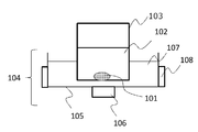
- a container 103 containing a gallium 101 and a solvent 102 containing at least one of an acid or an alkali is installed in the ultrasonic generator 104.
- the ultrasonic generator 104 includes, for example, a water tank 105, an oscillator 106, a medium 107, and a heating means 108. Either gallium 101 or solvent 102 may be put into the container 103 first.
- Gallium 101 is preferably liquefied before the step of miniaturization. This further facilitates the miniaturization of gallium 101.
- the frequency of the ultrasonic waves emitted from the vibrator 106 is not limited as long as the gallium 101 can be miniaturized, but it is preferably 20 kHz or more and 1000 kHz or less, for example.
- the gallium 101 is refined from a millimeter unit to a micrometer unit in diameter to increase the surface area, so that a chemical reaction on the gallium surface is promoted and the gallium 101 is efficiently dissolved.
- the medium 107 propagates the ultrasonic waves oscillated from the vibrator 106 and transmits the ultrasonic waves to the solvent 102 and the gallium 101 in the container 103, and it is preferable to use water, which is heated from 30 ° C. to 100 ° C. by the heating means 108. More preferably, by keeping the temperature between 30 ° C. and 60 ° C., the chemical reaction between the solvent 102 and the gallium 101 is further promoted, and the gallium 101 can be dissolved more efficiently.
- a hydrohalic acid more preferably a hydrochloride, a hydrobromic acid or a hydroiodic acid, and most preferably a hydroiodic acid.
- hydrogen iodide acid for example, 1 to 12 N (concentration 55 to 58%) of hydrogen iodide acid can be used, and this may be used as it is or diluted with pure water.
- ammonia for example, ammonium hydroxide can be used.
- ammonium hydroxide having a concentration of 1 to 12 N (concentration 28 to 40%) can be used, and this may be used as it is or diluted with pure water.
- the above acid and alkali can be mixed and the pH of the solvent 102 can be appropriately adjusted before use.
- gallium precursor By completely dissolving gallium 101 in this way, a gallium precursor can be obtained.
- the gallium concentration of the gallium precursor can be adjusted according to the purpose, but from the viewpoint of productivity, it is preferably 0.1 mol / L to 5 mol / L, and is about 1 mol / L to 3.5 mol / L. It is more preferable to do so.
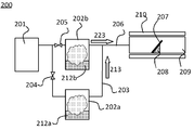
- FIG. 2 shows an example of an apparatus used in the method for manufacturing a laminate according to the present invention.
- the mist CVD apparatus 200 is used.
- the mist CVD apparatus 200 includes a carrier gas 201, an atomizer 202a, an atomizer 202b, a transfer pipe 203, a valve 204, a valve 205, a transfer pipe 206, a base 207, a susceptor 208, a film forming chamber 209, and a heating means 210. I have.
- the atomizers 202a and 202b contain the first precursor solution 212a and the second precursor solution 212b as raw materials, respectively, and atomize using known means (also referred to as "mistification"). Says) and mist is formed.
- the mist referred to in the present invention refers to fine particles of a liquid dispersed in a gas, includes what is called a mist or a droplet, and may be a mist or a droplet.
- a precursor solution obtained by appropriately adjusting the concentration of the gallium precursor obtained by the above-described gallium precursor production method with pure water is used.
- the gallium concentration in the precursor solutions 212a and 212b is not particularly limited and can be appropriately set according to the purpose and specifications. It is preferably 0.001 mol / L or more to 2 mol / L, and more preferably 0.01 mol / L or more and 0.7 mol / L or less.
- the components of the first precursor solution 212a and the second precursor solution 212b may be the same or different.
- the gallium precursor solution can be used as the first precursor solution 212a
- the aluminum precursor solution can be used as the second precursor solution 212b.
- Impurities may be added to the precursor solutions 212a and 212b.
- n-type dopants such as tin, germanium, silicon, titanium, zirconium, vanadium and niobium
- p-type dopants such as copper, silver, tin, iridium and rhodium
- Complexes and compounds containing these can be preferably used, and tin halide is particularly preferable.
- These impurity raw materials can be used at a ratio of 0.0001% to 20%, more preferably 0.001% to 10%, based on the gallium concentration of the precursor solution. Further, these impurities may be mixed with the gallium precursor solution and used, or the gallium precursor solution is prepared separately as the first precursor solution 212a and the impurity solution is separately prepared as the second precursor solution 212b and mixed in the form of mist. You may.
- the means for atomizing the precursor solutions 212a and 212b is not particularly limited as long as it can be atomized or atomized, and may be known means, but in the present invention, the means for atomizing using ultrasonic waves is preferable. ..
- the mist or droplet obtained by using ultrasonic waves has a zero initial velocity and is preferable because it floats in the air. For example, it is possible to float in space and carry it as a gas instead of spraying it like a spray. Since it is possible, it is very suitable because it is not damaged by collision energy.
- the droplet size is not particularly limited and may be a droplet of about several mm, but is preferably 50 ⁇ m or less, and more preferably 0.1 to 10 ⁇ m.
- the carrier gas 201 is mixed with the atomized raw material (precursor solution) formed in the atomizers 202a and 202b to become the first air-fuel mixture 213 and the second air-fuel mixture 223, respectively, and is conveyed to the film forming chamber 209. Will be done.
- the air-fuel mixture supplied to the film-forming chamber 209 reacts in the film-forming chamber 209 on the substrate 207 heated by the heating means 210 to form a film.
- a structure is shown in which the atomizer 202b and the film forming chamber 209 are connected by a transfer pipe 206, and the transfer pipe 203 from the atomizer 202a joins in the middle of the transfer pipe 206.
- the transport pipe 203 and the transport pipe 206 may be independently connected to the film forming chamber 209.
- the present invention is not limited to this, and the first air-fuel mixture 213 and the second air-fuel mixture 223 may be introduced into a single buffer tank (not shown), and the mist mixed in the buffer tank may be conveyed to the film forming chamber 209.
- the carrier gas 201 is not particularly limited, and for example, in addition to air, oxygen, and ozone, an inert gas such as nitrogen and argon, or a reducing gas such as hydrogen gas and forming gas is preferably used.
- an inert gas such as nitrogen and argon, or a reducing gas such as hydrogen gas and forming gas is preferably used.
- the type of carrier gas may be one type or two or more types.
- the flow rate of the carrier gas may be appropriately set according to the size of the substrate and the size of the film forming chamber, and can be about 0.01 to 100 L / min.
- the film formation may be performed under any conditions of atmospheric pressure, pressurization and depressurization, but it is preferable to perform the film formation under atmospheric pressure in terms of equipment cost and productivity.
- the flow rate of the diluting gas may be appropriately set, and may be, for example, 0.1 to 10 times / min of the carrier gas.
- Diluted gas may be supplied to, for example, the downstream side of the atomizers 202a and 202b. Further, the diluting gas may be the same as the carrier gas, or may be different.
- the transport pipes 203 and 206 are not particularly limited as long as they have sufficient stability with respect to the solvent of the precursor and the temperature at the connection between the reactor and the transport pipe, and quartz, polyethylene, polypropylene, vinyl chloride, silicone General resin pipes such as resin, urethane resin, and fluororesin can be widely used.
- the structure of the film-forming chamber 209 is not particularly limited, and metals such as aluminum and stainless steel may be used, and quartz or carbide is used when film-forming is performed at a higher temperature exceeding the heat-resistant temperature of these metals. Silicon may be used.
- a heating means 210 for heating the substrate 207 is provided inside or outside the film forming chamber 209. Further, the substrate 207 may be placed on the susceptor 208 installed in the film forming chamber 209.
- the above-mentioned substrate is not particularly limited as long as it can support the film to be formed.
- the material of the substrate may be a known material, an organic compound, or an inorganic compound.
- examples include, but are not limited to, gallium, SiC, ZnO, GaN and the like.
- the shape of the substrate may be, for example, plate-like, fibrous, rod-like, columnar, prismatic, tubular, spiral, spherical, ring-like, or the like such as a flat plate or a disk.
- the thickness thereof is not particularly limited in the present invention, but is preferably 50 to 2000 ⁇ m, and more preferably 200 to 800 ⁇ m.
- the substrate is a substrate containing a crystal having a corundum structure as a main component or a substrate containing a crystal having a ⁇ -gaul structure as a main component.
- the main component refers to a substance containing 50% or more of the component.
- Examples of the substrate containing a crystal having a corundum structure as a main component include sapphire (eg, c-plane sapphire substrate) and ⁇ -type gallium oxide.
- a substrate containing a crystal having a ⁇ -Galia structure as a main component for example, a ⁇ -Ga 2 O 3 substrate or a Ga 2 O 3 and Al 2 O 3 are included, and Al 2 O 3 is 0% by mass.
- substrates having a hexagonal structure examples include substrates having a hexagonal structure (eg, SiC, ZnO, GaN, LiTaO 3 ) and the like.
- a film may be formed on the substrate having a hexagonal structure directly or via another layer (eg, a buffer layer).
- Example 1 20 g of liquefied gallium was weighed in a glass beaker made of borosilicate, and 145 mL of hydrogen iodide having a concentration of 56.3% was added thereto. This was installed in an ultrasonic generator maintained at a water temperature of 40 ° C., and gallium was vibrated and refined by ultrasonic waves having a frequency of 38 kHz. In this state, the gallium was left to be completely dissolved to prepare a 2 mol / L gallium precursor.
- the time required for dissolution was measured and found to be 2 hours and 40 minutes.
- Example 1 A gallium precursor was prepared in the same manner as in Example 1 except that ultrasonic vibration was not applied to gallium. The time required for dissolution was measured and found to be 276 hours.
- Example 1 The result of Example 1 was that the time required for producing the gallium precursor was significantly shortened as compared with Comparative Example 1.
- Example 2 A gallium oxide film was formed by a mist CVD apparatus under the following conditions. First, the gallium precursor prepared in Example 1 was diluted with pure water to use a 0.05 mol / L precursor solution as a raw material solution, and the raw material solution was filled in an atomizer.
- a c-plane sapphire substrate having a diameter of 4 inches (100 mm) and a thickness of 0.6 mm was placed on a quartz susceptor and installed in a quartz tubular film-forming chamber, and the temperature of the c-plane sapphire substrate was raised to 450 ° C. by a heater. I kept it.
- the raw material solution in the atomizer was atomized with a 2.4 MHz ultrasonic vibrator. After that, nitrogen of the carrier gas is introduced into the atomizer at 1.5 L / min and nitrogen of the diluted gas is introduced at 5 L / min to form an air-fuel mixture, which is supplied to the film forming chamber to form a film. It was.
- the crystallinity and carbon concentration of the obtained film were evaluated by the XRD method and the SIMS method, respectively.
- Example 2 The film formation and evaluation were carried out in the same manner as in Example 2 except that gallium acetylacetonate was dissolved in a dilute aqueous hydrochloric acid solution (hydrochloric acid concentration 2%) to prepare a precursor solution of 0.05 mol / L.
- Table 1 shows the evaluation results of Example 2 and Comparative Example 2.
- the formed film was ⁇ -Ga 2 O 3 , but the result of Example 2 was that the half width of the locking curve was improved and the impurity concentration was significantly reduced as compared with Comparative Example 2.
- Example 2 was that the half width of the locking curve was improved and the impurity concentration was significantly reduced as compared with Comparative Example 2.
- the productivity of the gallium precursor can be remarkably improved as compared with the prior art, and when the gallium precursor obtained by the method of the present invention is used, the productivity is higher than that of the prior art. It was found that a high quality film could be obtained.
- the present invention is not limited to the above embodiment.
- the above-described embodiment is an example, and any object having substantially the same configuration as the technical idea described in the claims of the present invention and exhibiting the same effect and effect is the present invention. Is included in the technical scope of.
Abstract
本発明は、ガリウム前駆体を作製する方法であって、酸及び/又はアルカリを含む水溶液からなる溶媒を準備するステップと、前記溶媒にガリウムを浸漬するステップと、前記溶媒に浸漬した前記ガリウムを微細化するステップと、前記微細化した前記ガリウムを溶解するステップと、を含むガリウム前駆体の製造方法である。これにより、高品質で生産性の高いガリウム前駆体の製造方法が提供される。
Description
本発明は、ガリウム含有膜積層体の製造に有用なガリウム前駆体の製造方法と、これを用いた積層体の製造方法に関する。
低温、大気圧でエピタキシャル膜などが形成可能な方法として、ミストCVD法等の水微粒子を用いた成膜手法が知られている。
特許文献1では、ガリウムアセチルアセトナートを塩酸などの酸に溶解して前駆体とし、この前駆体を霧化することによって原料微粒子を生成し、この原料微粒子とキャリアガスを混合した混合気をサファイアなどコランダム構造の基板の表面に供給し、原料ミストを反応させることで基板上に単一配向した酸化ガリウム薄膜をエピタキシャル成長させている。
また特許文献2には、ガリウムを塩酸、臭化水素酸、フッ化水素酸、ヨウ化水素酸などで、1から2週間程度かけて溶解することで得られたハロゲン化ガリウム水溶液を用いる方法が記載されている。
ところが、特許文献1の方法は、前駆体に有機錯体を用いるため、得られる膜の炭素濃度が高く、高品質な膜が得られなかった。
また特許文献2に記載の方法は、ガリウムの溶解に長時間を要するため、実用には向かないものであった。
本発明は上記のような問題を鑑みてなされたもので、前駆体製造に有機錯体を用いないことで、得られる膜中の炭素濃度を抑制し高品質な膜の製造を可能にし、また前記前駆体製造におけるガリウムの溶解に要する時間を短縮することで、ガリウム前駆体を高い生産性で製造する方法を提供することを目的とする。
上記目的を達成するために、本発明は、ガリウム前駆体を作製する方法であって、酸及び/又はアルカリを含む水溶液からなる溶媒を準備するステップと、前記溶媒にガリウムを浸漬するステップと、前記溶媒に浸漬した前記ガリウムを微細化するステップと、前記微細化した前記ガリウムを溶解するステップと、を含むガリウム前駆体の製造方法を提供する。
このようなガリウム前駆体製造方法であれば、短時間で前記ガリウムを溶解でき、有機錯体を用いないガリウム前駆体を高い生産性で製造することができる。
このとき、前記ガリウムを微細化するステップは、超音波振動により行われると良い。
このようにすれば、前記ガリウムの微細化を容易にできるとともに、前記ガリウムの溶解をさらに促進することができる。
このとき、前記ガリウムを微細化するステップ以前に、さらに前記ガリウムを液化することができる。
このようにすれば、ガリウムの溶解時間をさらに短縮することができる。
このとき、前記ガリウムを溶解するステップにおいて前記溶媒の温度は、30℃以上100℃未満の温度に保たれると良い。
このようにすれば、ガリウムの溶解をさらに促進することができる。
このとき、前記酸としては、ハロゲン化水素を用いることができ、また前記アルカリとしては、アンモニアを用いることができる。
このようにすれば、ガリウム前駆体を高純度なものとすることができる。
また本発明は、ガリウムを含有する膜を含む積層体の製膜方法であって、基体を加熱するステップと、上記の方法で作製したガリウム前駆体を、さらに水で希釈してガリウム前駆体溶液を作製するステップと、前記ガリウム前駆体溶液を霧化するステップと、前記霧化された前記ガリウム前駆体溶液をキャリアガスで前記基体に供給するステップと、前記基体上で前記霧化された前記ガリウム前駆体溶液を反応させ、前記ガリウムを含有する膜を形成するステップと、を含む積層体の製造方法を提供する。
このようにすれば、不純物の少ない高品質な積層体を高い生産性で得ることができる。
本発明のガリウム前駆体製造方法によれば、高品質なガリウム前駆体を高い生産性で製造することができる。
また、本発明のガリウム前駆体製造方法を用いた製膜方法によれば、不純物の少ない高品質なガリウム含有膜の積層体を容易且つ低コストで製造することができる。
上述した通り、炭素濃度を抑制した高品質な膜の製造方法と、膜の製造に使用するガリウム前駆体を高い生産性で製造する方法が求められていた。
そして、本発明者は上記課題を解決するために鋭意検討を重ねた結果、前駆体製造に有機錯体を用いないことで、得られる膜中の炭素濃度を抑制し高品質な膜の製造を可能にし、また前記前駆体製造時におけるガリウムの溶解に要する時間を短縮することで、ガリウム前駆体を高い生産性で製造する方法を見出し、本発明に到達した。
即ち、本発明は、ガリウム前駆体を作製する方法であって、酸及び/又はアルカリを含む水溶液からなる溶媒を準備するステップと、前記溶媒にガリウムを浸漬するステップと、前記溶媒に浸漬した前記ガリウムを微細化するステップと、前記微細化した前記ガリウムを溶解するステップと、を含むことを特徴とするガリウム前駆体の製造方法を提供する。
本発明のガリウム前駆体製造方法によれば、高品質なガリウム前駆体を高い生産性で製造することができる。また、本発明のガリウム前駆体製造方法を用いた製膜方法によれば、不純物の少ない高品質なガリウム含有膜の積層体を容易且つ低コストで製造することができる。
以下、本発明について図1および図2を参照しながら詳細に説明するが、本発明はこれに限定されるものではない。
本発明に係るガリウム前駆体は、酸及び/又はアルカリを含む水溶液からなる溶媒にガリウムを溶解させた溶液である。
本発明のガリウム前駆体製造方法は、溶媒に浸漬したガリウムを微細化するステップと、前記微細化した前記ガリウムを溶解するステップに特徴を有する製造方法である。なお、微細化する方法は特に限定されないが、超音波振動により微細化することが好ましい。
図1に示すように、まずガリウム101と酸またはアルカリのいずれかを少なくとも含む溶媒102の入った容器103を超音波発生器104に設置する。超音波発生器104は、例えば、水槽105、振動子106、媒体107および加熱手段108を備えている。なお、ガリウム101と溶媒102はどちらを先に容器103へ入れてもよい。
ガリウム101は、微細化するステップ以前に液化しておくのが好ましい。これによりガリウム101の微細化がさらに容易になる。
ただし、ガリウムを秤量する際、液化ガリウムを使用する場合は、ガリウムの濡れ性が非常に強いため、別容器などでは行わず、溶媒102を入れる前の容器103に直接ガリウムを入れて行うのが好ましい。
振動子106から発する超音波の周波数は、ガリウム101を微細化可能であれば限定はされないが、例えば、20kHz以上1000kHz以下とするのが好ましい。これによりガリウム101はミリメートル単位からマイクロメートル単位の径に微細化されて表面積が増加するので、ガリウム表面での化学反応が促進されて効率よく溶解される。
また媒体107は振動子106から発振された超音波を伝搬し、容器103内の溶媒102及びガリウム101に伝えるもので、水を用いるのが好ましく、これを加熱手段108により30℃から100℃、より好ましくは30℃から60℃に保つことで、溶媒102とガリウム101の化学反応がさらに促進されて、より効率的にガリウム101を溶解できる。
溶媒102に酸を用いる場合は、ハロゲン化水素酸を使用するのが好ましく、塩化水素酸、臭化水素酸またはヨウ化水素酸であることがより好ましく、ヨウ化水素酸であるのが最も好ましい。ヨウ化水素酸を使用する場合、例えば1~12N(濃度55~58%)のヨウ化水素酸が使用でき、これをそのまま、あるいは純水で希釈して用いて良い。
溶媒にアルカリを用いる場合は、アンモニアを用いることが好ましく、例えば、水酸化アンモニウムを使用できる。この場合、例えば1~12N(濃度28~40%)の水酸化アンモニウムが使用でき、これをそのまま、あるいは純水で希釈して用いて良い。
また、上記酸とアルカリを混合し、溶媒102のpHを適宜調整して用いることもできる。
このようにしてガリウム101を完全に溶解することで、ガリウム前駆体が得られる。
ガリウム前駆体のガリウム濃度は、目的に応じて調整することができるが、生産性の観点から0.1mol/Lから5mol/Lとするのが好ましく、1mol/Lから3.5mol/L程度とするのがより好ましい。
次に、上記製造方法により製造したガリウム前駆体を用いた、ガリウム含有膜積層体の製造方法の一例について図2を参照しながら説明するが、本発明はこれに限定されるものではない。
図2に、本発明に係る積層体の製造方法に用いる装置の一例を示す。本発明に係る積層体の製造方法においては、ミストCVD装置200を用いる。ミストCVD装置200は、キャリアガス201、霧化器202a、霧化器202b、搬送配管203、バルブ204、バルブ205、搬送配管206、基体207、サセプタ208、製膜室209、加熱手段210、を備えている。
まず、霧化器202a、202b内には、原料として、それぞれ、第1前駆体溶液212a、第2前駆体溶液212bが収納されており、公知の手段を用いて霧化(「ミスト化」とも言う)され、ミストが形成される。なお、本発明でいうミストとは、気体中に分散した液体の微粒子を指し、霧、液滴と呼ばれるものを含み、霧、液滴ということもある。
第1前駆体溶液212aと第2前駆体溶液212bの少なくとも片方には、上記記載のガリウム前駆体製造方法で得られたガリウム前駆体を純水で適宜濃度調整をした前駆体溶液が用いられる。
前駆体溶液212a、212b中のガリウム濃度は、特に限定されず、目的や仕様に応じて適宜設定できる。好ましくは、0.001mol/L以上から2mol/Lであり、より好ましくは0.01mol/L以上0.7mol/L以下である。
また、第1前駆体溶液212aと第2前駆体溶液212bの成分は、同一でもよいし異なっていてもよい。例えばガリウムとアルミニウムからなる2元系の酸化物を形成する場合などは、ガリウム前駆体溶液を第1前駆体溶液212aとし、アルミニウム前駆体溶液を第2前駆体溶液212bとして用いることができる。
また前駆体溶液212a、212bへは、不純物を添加しても良い。例えば酸化ガリウムを形成する場合には、スズ、ゲルマニウム、ケイ素、チタン、ジルコニウム、バナジウム又はニオブ等のn型ドーパント、又は、銅、銀、スズ、イリジウム、ロジウム等のp型ドーパントなどが挙げられる。これらを含む錯体や化合物は好適に使用でき、特にハロゲン化スズを用いるのが好ましい。
これらの不純物原料を、前駆体溶液のガリウム濃度に対して0.0001%~20%、より好ましくは0.001%~10%の割合で用いることができる。またこれら不純物はガリウム前駆体溶液に混合して用いても良いし、ガリウム前駆体溶液を第1前駆体溶液212aとし、不純物溶液を第2前駆体溶液212bとして別々に用意し、ミスト状で混合しても良い。
前駆体溶液212a、212bの霧化手段は、霧化または液滴化できさえすれば特に限定されず、公知の手段であってよいが、本発明においては、超音波を用いる霧化手段が好ましい。
超音波を用いて得られた霧または液滴は、初速度がゼロであり、空中に浮遊するので好ましく、例えば、スプレーのように吹き付けるのではなく、空間に浮遊してガスとして搬送することが可能であるので、衝突エネルギーによる損傷がないため非常に好適である。
液滴サイズは特に限定されず、数mm程度の液滴であってもよいが、好ましくは50μm以下であり、より好ましくは0.1~10μmである。
キャリアガス201は、霧化器202a、202b内で形成された霧化した原料(前駆体溶液)と混合され、それぞれ第1混合気213、第2混合気223となり、製膜室209へと搬送される。
製膜室209に供給された混合気は、製膜室209内で加熱手段210により加熱された基体207上で反応し、膜が形成される。
図2に示す例では、霧化器202bと製膜室209とが搬送配管206で接続され、霧化器202aからの搬送配管203が搬送配管206の途中に合流する構造が示されているが、搬送配管203と搬送配管206が独立して製膜室209へ接続されていてもよい。またこれに限らず、第1混合気213と第2混合気223を単一のバッファタンク(不図示)に導入し、バッファタンクで混合されたミストを製膜室209へ搬送しても良い。
キャリアガス201は、特に限定されず、例えば、空気、酸素、オゾンの他、窒素やアルゴン等の不活性ガス、又は水素ガスやフォーミングガス等の還元ガスが好適に用いられる。キャリアガスの種類は1種類であっても、2種類以上であってもよい。
キャリアガスの流量は、基体サイズや製膜室の大きさにより適宜設定すればよく、0.01~100L/min程度とすることができる。
また製膜は、大気圧下、加圧下及び減圧下のいずれの条件下で行われてもよいが、装置コストや生産性の面で、大気圧下で行われるのが好ましい。
また、図示していないが、希釈ガスを添加して、霧化された前駆体溶液とキャリアガスの割合を調節することも可能である。希釈ガスの流量は適宜設定すればよく、例えばキャリアガスの0.1~10倍/分とすることができる。
希釈ガスを、例えば霧化器202a、202bの下流側へ供給しても良い。また、希釈ガスはキャリアガスと同じものを用いても良いし、異なるものを用いても良い。
搬送配管203、206は、前駆体の溶媒や反応器と搬送配管の取り合いにおける温度などに対して十分な安定性を持つものであれば特に限定されず、石英やポリエチレン、ポリプロピレン、塩化ビニル、シリコーン樹脂、ウレタン樹脂、フッ素樹脂などといった一般的な樹脂製の配管を広く用いることができる。
製膜室209の構造等は特に限定されるものではなく、アルミニウムやステンレスなどの金属を用いて良いし、これらの金属の耐熱温度を超える、より高温で製膜を行う場合には石英や炭化シリコンを用いても良い。製膜室209の内部又は外部には、基体207を加熱するための加熱手段210が設けられている。また、基体207は製膜室209内に設置されたサセプタ208上に載置されてよい。
なお上記基体は、形成する膜を支持できるものであれば特に限定されない。基体の材料は、公知のものであってよく、有機化合物であってもよいし、無機化合物であってもよい。例えば、ポリサルフォン、ポリエーテルサルフォン、ポリフェニレンサルファイド、ポリエーテルエーテルケトン、ポリイミド、ポリエーテルイミド、フッ素樹脂、鉄やアルミニウム、ステンレス鋼、金等の金属、シリコン、サファイア、石英、ガラス、炭酸カルシウム、酸化ガリウム、SiC、ZnO、GaN等が挙げられるが、これに限られるものではない。
基体の形状としては、例えば、平板や円板等の板状、繊維状、棒状、円柱状、角柱状、筒状、螺旋状、球状、リング状などが挙げられいずれでも構わない。特に基体が板状体の場合、その厚さは、本発明においては特に限定されないが、好ましくは、50~2000μmであり、より好ましくは200~800μmである。
本発明においては、上記基体が、コランダム構造を有する結晶物を主成分として含む基体、またはβ-ガリア構造を有する結晶物を主成分として含む基体であるのも好ましい。ここで、主成分とは、当該成分を50%以上含有する物を指す。
コランダム構造を有する結晶を主成分とする基板としては、例えば、サファイア(例:c面サファイア基板)や、α型酸化ガリウムなどが挙げられる。
また、β-ガリア構造を有する結晶物を主成分とする基体としては、例えばβ-Ga2O3基板、又はGa2O3とAl2O3とを含みAl2O3が0質量%より多くかつ60質量%以下である混晶体基板、公知の基板上にβ-Ga2O3を成膜した基板、などが挙げられる。
その他の基体の例としては、六方晶構造を有する基体(例:SiC、ZnO、GaN、LiTaO3)などが挙げられる。六方晶構造を有する基体上には、直接または別の層(例:緩衝層)を介して、膜を形成してもよい。
以下、実施例及び比較例を用いて本発明を具体的に説明するが、本発明はこれらに限定されるものではない。
(実施例1)
硼珪酸ガラス製ビーカーに液化したガリウムを20g秤量し、これに濃度56.3%のヨウ化水素酸145mLを加えた。これを水温40℃に保った超音波発生器に設置し、周波数38kHzの超音波でガリウムを振動、微細化した。この状態でガリウムが完全に溶解するまで放置し、2mol/Lのガリウム前駆体を作製した。
硼珪酸ガラス製ビーカーに液化したガリウムを20g秤量し、これに濃度56.3%のヨウ化水素酸145mLを加えた。これを水温40℃に保った超音波発生器に設置し、周波数38kHzの超音波でガリウムを振動、微細化した。この状態でガリウムが完全に溶解するまで放置し、2mol/Lのガリウム前駆体を作製した。
溶解に要した時間を測定したところ、2時間40分であった。
(比較例1)
ガリウムに超音波振動を加えなかった以外は、実施例1と同様にガリウム前駆体を作製した。溶解に要した時間を測定したところ、276時間であった。
ガリウムに超音波振動を加えなかった以外は、実施例1と同様にガリウム前駆体を作製した。溶解に要した時間を測定したところ、276時間であった。
実施例1の結果は比較例1にくらべ、ガリウム前駆体の製造所要時間が大幅に短縮された。
(実施例2)
ミストCVD装置により、以下の条件で酸化ガリウムの製膜を行った。まず実施例1で作製したガリウム前駆体を純水で希釈して0.05mol/Lの前駆体溶液を原料溶液とし、前記原料溶液を霧化器に充填した。
ミストCVD装置により、以下の条件で酸化ガリウムの製膜を行った。まず実施例1で作製したガリウム前駆体を純水で希釈して0.05mol/Lの前駆体溶液を原料溶液とし、前記原料溶液を霧化器に充填した。
次に、直径4インチ(100mm)、厚さ0.6mmのc面サファイア基板を、石英製サセプタに載せて石英製管状型製膜室内に設置し、ヒーターにより前記c面サファイア基板温度を450℃に保った。
次に2.4MHzの超音波振動子で霧化器内の前記原料溶液を霧化した。この後、霧化器にキャリアガスの窒素を1.5L/minで、さらに希釈ガスの窒素を5L/minでそれぞれ導入して混合気を形成し、製膜室へ供給して製膜を行った。
得られた膜の結晶性と炭素濃度をXRD法およびSIMS法によりそれぞれ評価した。
(比較例2)
ガリウムアセチルアセトナートを希塩酸水溶液(塩酸濃度2%)で溶解して0.05mol/Lの前駆体溶液を用意したこと以外は、実施例2と同様に製膜と評価を行った。
ガリウムアセチルアセトナートを希塩酸水溶液(塩酸濃度2%)で溶解して0.05mol/Lの前駆体溶液を用意したこと以外は、実施例2と同様に製膜と評価を行った。
表1は実施例2と比較例2の評価結果である。いずれの場合も、形成された膜はα―Ga2O3であったが、実施例2の結果は比較例2に比べ、ロッキングカーブ半値幅が改善され、不純物濃度が大幅に低減されていることが示された。

上記の結果から、本発明によれば従来技術よりもガリウム前駆体の生産性を格段に改善することができ、また本発明の方法で得られたガリウム前駆体を用いれば、従来技術よりも高品質な膜が得られることがわかった。
なお、本発明は、上記実施形態に限定されるものではない。上記実施形態は例示であり、本発明の特許請求の範囲に記載された技術的思想と実質的に同一な構成を有し、同様な作用効果を奏するものは、いかなるものであっても本発明の技術的範囲に包含される。
Claims (7)
- ガリウム前駆体を作製する方法であって、
酸及び/又はアルカリを含む水溶液からなる溶媒を準備するステップと、前記溶媒にガリウムを浸漬するステップと、前記溶媒に浸漬した前記ガリウムを微細化するステップと、前記微細化した前記ガリウムを溶解するステップと、
を含むことを特徴とするガリウム前駆体の製造方法。 - 前記ガリウムを微細化するステップは、超音波振動により前記ガリウムを微細化することを特徴とする請求項1に記載のガリウム前駆体の製造方法。
- 前記ガリウムを微細化するステップ以前に、さらに前記ガリウムを液化することを含むことを特徴とする請求項1または2に記載のガリウム前駆体の製造方法。
- 前記ガリウムを溶解するステップにおいて前記溶媒の温度を、30℃以上100℃未満に保つことを特徴とする請求項1から3のいずれか1項に記載のガリウム前駆体の製造方法。
- 前記酸として、ハロゲン化水素を用いることを特徴とする請求項1から4のいずれか1項に記載のガリウム前駆体の製造方法。
- 前記アルカリとして、アンモニアを用いることを特徴とする請求項1から5のいずれか1項に記載のガリウム前駆体の製造方法。
- ガリウムを含有する膜を含む積層体の製膜方法であって、
基体を加熱するステップと、請求項1から6のいずれか1項に記載の方法で作製した前記ガリウム前駆体を、さらに水で希釈してガリウム前駆体溶液を作製するステップと、前記ガリウム前駆体溶液を霧化するステップと、前記霧化された前記ガリウム前駆体溶液をキャリアガスで前記基体に供給するステップと、前記基体上で前記霧化された前記ガリウム前駆体溶液を反応させ、前記ガリウムを含有する膜を形成するステップと、
を含むことを特徴とする積層体の製造方法。
Priority Applications (4)
| Application Number | Priority Date | Filing Date | Title |
|---|---|---|---|
| KR1020227012965A KR20220088423A (ko) | 2019-10-24 | 2020-07-15 | 갈륨 전구체의 제조 방법 및 이것을 사용한 적층체의 제조 방법 |
| EP20878229.2A EP4050133A4 (en) | 2019-10-24 | 2020-07-15 | METHOD OF MAKING A GALLIUM PRECURSOR AND METHOD OF MAKING A LAYERED PRODUCT USING THE SAME |
| CN202080073090.0A CN114555872A (zh) | 2019-10-24 | 2020-07-15 | 镓前驱体的制备方法及使用了该镓前驱体的层叠体的制造方法 |
| US17/766,467 US20240102159A1 (en) | 2019-10-24 | 2020-07-15 | Method for producing gallium precursor and method for producing laminated body using the same |
Applications Claiming Priority (2)
| Application Number | Priority Date | Filing Date | Title |
|---|---|---|---|
| JP2019193265A JP7170617B2 (ja) | 2019-10-24 | 2019-10-24 | ガリウム前駆体の製造方法およびこれを用いた積層体の製造方法 |
| JP2019-193265 | 2019-10-24 |
Publications (1)
| Publication Number | Publication Date |
|---|---|
| WO2021079571A1 true WO2021079571A1 (ja) | 2021-04-29 |
Family
ID=75620649
Family Applications (1)
| Application Number | Title | Priority Date | Filing Date |
|---|---|---|---|
| PCT/JP2020/027420 WO2021079571A1 (ja) | 2019-10-24 | 2020-07-15 | ガリウム前駆体の製造方法およびこれを用いた積層体の製造方法 |
Country Status (7)
| Country | Link |
|---|---|
| US (1) | US20240102159A1 (ja) |
| EP (1) | EP4050133A4 (ja) |
| JP (2) | JP7170617B2 (ja) |
| KR (1) | KR20220088423A (ja) |
| CN (1) | CN114555872A (ja) |
| TW (1) | TW202132638A (ja) |
| WO (1) | WO2021079571A1 (ja) |
Cited By (1)
| Publication number | Priority date | Publication date | Assignee | Title |
|---|---|---|---|---|
| CN115786743A (zh) * | 2022-12-19 | 2023-03-14 | 广东省科学院资源利用与稀土开发研究所 | 一种制备高纯镓的装置和方法 |
Citations (6)
| Publication number | Priority date | Publication date | Assignee | Title |
|---|---|---|---|---|
| JPH10338522A (ja) * | 1997-06-04 | 1998-12-22 | Mitsui Mining & Smelting Co Ltd | 酸化ガリウム粉末の製造方法 |
| JP2009029694A (ja) * | 2007-06-29 | 2009-02-12 | Sumitomo Chemical Co Ltd | 酸化ガリウム及びその製造方法 |
| JP2014019590A (ja) * | 2012-07-13 | 2014-02-03 | Dowa Electronics Materials Co Ltd | 硝酸ガリウム水溶液の製造方法 |
| JP5793732B2 (ja) | 2011-07-27 | 2015-10-14 | 高知県公立大学法人 | ドーパントを添加した結晶性の高い導電性α型酸化ガリウム薄膜およびその生成方法 |
| CN106809871A (zh) * | 2017-03-07 | 2017-06-09 | 中国科学院宁波材料技术与工程研究所 | 一种氧化铟纳米粉体的制备方法 |
| JP2018070422A (ja) | 2016-11-01 | 2018-05-10 | 国立大学法人 和歌山大学 | 酸化ガリウムの製造方法及び結晶成長装置 |
Family Cites Families (3)
| Publication number | Priority date | Publication date | Assignee | Title |
|---|---|---|---|---|
| TW201416323A (zh) * | 2012-10-18 | 2014-05-01 | Solar Applied Mat Tech Corp | 氧化鎵粉末及其製作方法 |
| TWI503418B (zh) * | 2012-12-18 | 2015-10-11 | Nat Inst Chung Shan Science & Technology | 一種利用超音波萃取及熱處理除去鎵中雜質的方法 |
| JP6651685B2 (ja) * | 2015-06-11 | 2020-02-19 | 株式会社Flosfia | 結晶性半導体膜、積層構造体および半導体装置 |
-
2019
- 2019-10-24 JP JP2019193265A patent/JP7170617B2/ja active Active
-
2020
- 2020-07-15 CN CN202080073090.0A patent/CN114555872A/zh active Pending
- 2020-07-15 US US17/766,467 patent/US20240102159A1/en active Pending
- 2020-07-15 KR KR1020227012965A patent/KR20220088423A/ko unknown
- 2020-07-15 EP EP20878229.2A patent/EP4050133A4/en active Pending
- 2020-07-15 WO PCT/JP2020/027420 patent/WO2021079571A1/ja active Application Filing
- 2020-10-22 TW TW109136651A patent/TW202132638A/zh unknown
-
2022
- 2022-11-01 JP JP2022175183A patent/JP2023017874A/ja active Pending
Patent Citations (6)
| Publication number | Priority date | Publication date | Assignee | Title |
|---|---|---|---|---|
| JPH10338522A (ja) * | 1997-06-04 | 1998-12-22 | Mitsui Mining & Smelting Co Ltd | 酸化ガリウム粉末の製造方法 |
| JP2009029694A (ja) * | 2007-06-29 | 2009-02-12 | Sumitomo Chemical Co Ltd | 酸化ガリウム及びその製造方法 |
| JP5793732B2 (ja) | 2011-07-27 | 2015-10-14 | 高知県公立大学法人 | ドーパントを添加した結晶性の高い導電性α型酸化ガリウム薄膜およびその生成方法 |
| JP2014019590A (ja) * | 2012-07-13 | 2014-02-03 | Dowa Electronics Materials Co Ltd | 硝酸ガリウム水溶液の製造方法 |
| JP2018070422A (ja) | 2016-11-01 | 2018-05-10 | 国立大学法人 和歌山大学 | 酸化ガリウムの製造方法及び結晶成長装置 |
| CN106809871A (zh) * | 2017-03-07 | 2017-06-09 | 中国科学院宁波材料技术与工程研究所 | 一种氧化铟纳米粉体的制备方法 |
Non-Patent Citations (1)
| Title |
|---|
| See also references of EP4050133A4 |
Cited By (1)
| Publication number | Priority date | Publication date | Assignee | Title |
|---|---|---|---|---|
| CN115786743A (zh) * | 2022-12-19 | 2023-03-14 | 广东省科学院资源利用与稀土开发研究所 | 一种制备高纯镓的装置和方法 |
Also Published As
| Publication number | Publication date |
|---|---|
| EP4050133A4 (en) | 2023-08-30 |
| JP2023017874A (ja) | 2023-02-07 |
| EP4050133A1 (en) | 2022-08-31 |
| KR20220088423A (ko) | 2022-06-27 |
| US20240102159A1 (en) | 2024-03-28 |
| CN114555872A (zh) | 2022-05-27 |
| TW202132638A (zh) | 2021-09-01 |
| JP2021066633A (ja) | 2021-04-30 |
| JP7170617B2 (ja) | 2022-11-14 |
Similar Documents
| Publication | Publication Date | Title |
|---|---|---|
| JP6478103B2 (ja) | 成膜装置および成膜方法 | |
| JP5397794B1 (ja) | 酸化物結晶薄膜の製造方法 | |
| JP7223515B2 (ja) | 成膜装置及び成膜方法 | |
| WO2020129625A1 (ja) | 酸化ガリウム膜の製造方法 | |
| JP6233959B2 (ja) | 酸化物結晶薄膜の製造方法 | |
| JP2022016426A (ja) | 酸化ガリウム半導体膜の製造方法及び成膜装置 | |
| JP2023015226A (ja) | 酸化ガリウム半導体膜及び原料溶液 | |
| WO2021079571A1 (ja) | ガリウム前駆体の製造方法およびこれを用いた積層体の製造方法 | |
| WO2022004279A1 (ja) | 成膜用ドーピング原料溶液の製造方法、積層体の製造方法、成膜用ドーピング原料溶液及び半導体膜 | |
| JP7011207B2 (ja) | 成膜用ドーピング原料溶液の製造方法、積層体の製造方法、成膜用ドーピング原料溶液及び半導体膜 | |
| JP2021163946A (ja) | 結晶膜の製造方法 | |
| US20240124974A1 (en) | Method of producing raw material solution, method of film-forming and production lot | |
| WO2023210381A1 (ja) | 成膜方法、成膜装置、及び積層体 | |
| WO2023058273A1 (ja) | 成膜装置およびこれを用いた結晶性半導体膜の成膜方法 | |
| EP4303338A1 (en) | Film forming method, film forming apparatus and multilayer body | |
| TWM639608U (zh) | 成膜裝置 | |
| JP2021163947A (ja) | 結晶膜の製造方法 | |
| KR20240067080A (ko) | 성막장치 및 이를 이용한 결정성 반도체막의 성막방법 | |
| TW202405226A (zh) | 成膜方法及成膜裝置 | |
| JP2021161012A (ja) | サファイア基板の表面処理方法 | |
| KR20240063901A (ko) | 성막방법, 성막장치 및 결정성 산화물막 |
Legal Events
| Date | Code | Title | Description |
|---|---|---|---|
| 121 | Ep: the epo has been informed by wipo that ep was designated in this application |
Ref document number: 20878229 Country of ref document: EP Kind code of ref document: A1 |
|
| WWE | Wipo information: entry into national phase |
Ref document number: 17766467 Country of ref document: US |
|
| NENP | Non-entry into the national phase |
Ref country code: DE |
|
| ENP | Entry into the national phase |
Ref document number: 2020878229 Country of ref document: EP Effective date: 20220524 |