WO2021075432A1 - 内燃機関の制御装置及び制御方法 - Google Patents
内燃機関の制御装置及び制御方法 Download PDFInfo
- Publication number
- WO2021075432A1 WO2021075432A1 PCT/JP2020/038652 JP2020038652W WO2021075432A1 WO 2021075432 A1 WO2021075432 A1 WO 2021075432A1 JP 2020038652 W JP2020038652 W JP 2020038652W WO 2021075432 A1 WO2021075432 A1 WO 2021075432A1
- Authority
- WO
- WIPO (PCT)
- Prior art keywords
- blow
- internal combustion
- combustion engine
- control device
- gas
- Prior art date
- Legal status (The legal status is an assumption and is not a legal conclusion. Google has not performed a legal analysis and makes no representation as to the accuracy of the status listed.)
- Ceased
Links
Images



Classifications
-
- F—MECHANICAL ENGINEERING; LIGHTING; HEATING; WEAPONS; BLASTING
- F01—MACHINES OR ENGINES IN GENERAL; ENGINE PLANTS IN GENERAL; STEAM ENGINES
- F01M—LUBRICATING OF MACHINES OR ENGINES IN GENERAL; LUBRICATING INTERNAL COMBUSTION ENGINES; CRANKCASE VENTILATING
- F01M13/00—Crankcase ventilating or breathing
-
- F—MECHANICAL ENGINEERING; LIGHTING; HEATING; WEAPONS; BLASTING
- F02—COMBUSTION ENGINES; HOT-GAS OR COMBUSTION-PRODUCT ENGINE PLANTS
- F02D—CONTROLLING COMBUSTION ENGINES
- F02D41/00—Electrical control of supply of combustible mixture or its constituents
- F02D41/02—Circuit arrangements for generating control signals
- F02D41/04—Introducing corrections for particular operating conditions
- F02D41/12—Introducing corrections for particular operating conditions for deceleration
-
- Y—GENERAL TAGGING OF NEW TECHNOLOGICAL DEVELOPMENTS; GENERAL TAGGING OF CROSS-SECTIONAL TECHNOLOGIES SPANNING OVER SEVERAL SECTIONS OF THE IPC; TECHNICAL SUBJECTS COVERED BY FORMER USPC CROSS-REFERENCE ART COLLECTIONS [XRACs] AND DIGESTS
- Y02—TECHNOLOGIES OR APPLICATIONS FOR MITIGATION OR ADAPTATION AGAINST CLIMATE CHANGE
- Y02T—CLIMATE CHANGE MITIGATION TECHNOLOGIES RELATED TO TRANSPORTATION
- Y02T10/00—Road transport of goods or passengers
- Y02T10/10—Internal combustion engine [ICE] based vehicles
- Y02T10/40—Engine management systems
Definitions
- the present invention relates to an internal combustion engine control device and a control method for controlling an internal combustion engine for a vehicle provided with a blow-by gas recirculation passage and an electronically controlled valve device provided in the blow-by gas recirculation passage.
- the intake control device for an internal combustion engine disclosed in Patent Document 1 includes a throttle valve for adjusting the flow rate of fresh air supplied from the outside to the combustion chamber and a PCV (Positive Crankcase) including blow-by gas supplied from the engine body to the intake passage. Ventilation)
- a PCV valve for adjusting the flow rate of gas is provided, and a control means for operating the PCV valve in the valve closing direction and the throttle valve in the valve opening direction is provided based on the start of fuel cutting.
- the blow-by gas accumulated in the blow-by gas recirculation passage or the like at the end of the fuel cut is blow-by gas.
- the present invention has been made in view of the conventional circumstances, and an object of the present invention is the amount of particulate matter emitted from the internal combustion engine when the supply of blow-by gas to the combustion chamber is restarted based on the end of the fuel cut. It is an object of the present invention to provide a control device and a control method for an internal combustion engine, which can prevent an increase in the amount of fuel and a sudden change in the output torque of the internal combustion engine.
- the electronically controlled valve device provided in the blow-by gas recirculation passage is operated in the valve closing direction based on the start of fuel cut in the internal combustion engine.
- the blow-by gas retention amount responds to the response of the operation of the electronically controlled valve device in the valve opening direction based on the end of the fuel cut and the operation of the electronically controlled valve device in the valve opening direction based on the end of the fuel cut. The more it is, the slower it is.
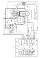
- FIG. 1 is a diagram showing an aspect of an internal combustion engine for a vehicle to which a control device and a control method for an internal combustion engine according to the present invention are applied.
- the internal combustion engine 1 shown in FIG. 1 is a spark-ignition gasoline engine used as a power source for a vehicle, and the engine main body 1a is provided with an ignition device 4, a fuel injection device 5, and the like.
- the fuel injection device 5 is arranged in the inlet manifold 2a and injects gasoline as fuel into the inlet manifold 2a.
- the intake air of the internal combustion engine 1 flows into the combustion chamber 10 together with the fuel injected by the fuel injection device 5 through the air cleaner 7, the electronically controlled throttle device 8, and the intake valve 19.
- the electronically controlled throttle device 8 is a device that opens and closes the throttle valve 8a with the throttle motor 8b, and adjusts the intake air amount of the internal combustion engine 1.
- the electronically controlled throttle device 8 includes a throttle opening sensor 8c that outputs a signal corresponding to the throttle opening TPS.
- the exhaust gas purification catalyst device 12 is arranged in the exhaust duct 3a, and purifies the exhaust gas of the internal combustion engine 1 by a three-way catalyst or the like.
- the rotation speed detecting device 6 outputs a signal of the rotation angle NE for each predetermined rotation angle of the crankshaft 14A by detecting the protrusion of the ring gear 14.
- the flow rate detection device 9 is arranged on the upstream side of the electronically controlled throttle device 8 and outputs a signal corresponding to the intake air flow rate QAR of the internal combustion engine 1.
- the oil temperature sensor 11 outputs a signal corresponding to the oil temperature TL, which is the temperature of the lubricating oil of the internal combustion engine 1.
- the outside air temperature sensor 15 outputs a signal corresponding to the outside air temperature TO, in other words, the air temperature outside the vehicle.
- the electronic odometer 16 measures the total mileage of the vehicle and outputs a signal corresponding to the total mileage ML.
- the intake pressure sensor 17 outputs a signal corresponding to the intake pressure PB, which is the pressure downstream of the electronically controlled throttle device 8.
- the control device 13 which is an electronic control device equipped with a microcomputer, captures detection signals such as throttle opening TPS, intake air flow rate QAR, rotation angle NE, oil temperature TL, outside air temperature TO, and integrated mileage ML. Then, the control device 13 calculates the fuel injection pulse width TI [ms] and the injection timing based on the captured sensor detection signal, and sends a valve opening command signal corresponding to the fuel injection pulse width TI to the fuel injection device 5 at the injection timing.
- the software includes a function of outputting and controlling the fuel injection amount and injection timing by the fuel injection device 5.
- control device 13 implements a fuel cut that temporarily stops the fuel injection by the fuel injection device 5 in the deceleration operation state of the internal combustion engine 1. For example, when the driver takes his / her foot off the accelerator pedal and the engine rotation speed is higher than the first threshold value, the control device 13 determines that the condition for starting the fuel cut is satisfied and injects fuel by the fuel injection device 5. Stop it.
- the control device 13 restarts the fuel injection by the fuel injection device 5 when the engine rotation speed falls below the second threshold value (second threshold value ⁇ first threshold value) while the fuel injection by the fuel injection device 5 is stopped. Also, when the driver depresses the accelerator pedal, the fuel injection by the fuel injection device 5 is restarted. Further, the control device 13 generates and outputs a command signal of the ignition device 4 and the electronically controlled throttle device 8, controls the ignition timing of the ignition device 4, the opening degree of the throttle valve 8a, and the like, and operates the internal combustion engine 1. To control.
- the control device 13 has an analog input circuit 20, an A / D conversion circuit 21, a digital input circuit 22, an output circuit 23, and the like, in order to input and output data such as measurement results of various sensors and operation amounts to be output to various devices.
- the I / O circuit 24 is provided.
- the control device 13 includes a microcomputer 31 including an MPU (Microprocessor Unit) 26, a ROM (Read Only Memory) 27, and a RAM (Random Access Memory) 28 in order to perform data arithmetic processing.
- MPU Microprocessor Unit
- ROM Read Only Memory
- RAM Random Access Memory
- the analog input circuit 20 acquires analog signals related to the intake air flow rate QAR, throttle opening TPS, oil temperature TL, outside temperature TO, intake pressure PB, and the like, and supplies the acquired analog signals to the A / D conversion circuit 21.
- the A / D conversion circuit 21 converts the acquired analog signal into a digital signal and outputs it on the bus 25.
- the digital input circuit 22 acquires digital signals related to the rotation angle NE, the integrated mileage ML, and the like, and outputs the acquired digital signals to the bus 25 via the I / O circuit 24.
- the MPU 26, ROM 27, RAM 28, timer / counter 29, and the like are connected to the bus 25. Then, the MPU 26, the ROM 27, and the RAM 28 exchange data via the bus 25.
- the clock generator 30 supplies a clock signal to the MPU 26, and the MPU 26 executes various calculations and processes in synchronization with the clock signal.
- the ROM 27 is composed of, for example, an EEPROM (Electrically Erasable Programmable Read-Only Memory) capable of erasing and rewriting data, and stores a program for operating the control device 13, setting data, initial values, and the like. The information stored in the ROM 27 is read into the RAM 28 and the MPU 26 via the bus 25.
- EEPROM Electrically Erasable Programmable Read-Only Memory
- the RAM 28 is used as a work area for temporarily storing the calculation result and the processing result by the MPU 26.
- the timer / counter 29 is used for measuring time, measuring various times, and the like. After being output on the bus 25, the calculation result and the processing result by the MPU 26 are supplied from the output circuit 23 to the ignition device 4, the fuel injection device 5, the electronically controlled throttle device 8, and the like via the I / O circuit 24.
- the internal combustion engine 1 includes a blow-by gas recirculation device 41.
- the blow-by gas recirculation device 41 is a device for returning blow-by gas containing vaporized fuel among unburned fuels leaked from the combustion chamber 10 of the internal combustion engine 1 into the crankcase 42 for storing the lubricating oil to the intake passage of the internal combustion engine 1. Is.
- the blow-by gas recirculation device 41 includes a first blow-by gas recirculation passage 43 that communicates the inside of the crankcase 42 with the inside of the intake collector portion 2b downstream of the electronically controlled throttle device 8, and an intake passage and a crankcase upstream of the electronically controlled throttle device 8.
- a second blow-by gas recirculation passage 45 communicating with the 42 and a PCV valve 44 provided in the first blow-by gas recirculation passage 43 are provided.
- the PCV valve 44 is an electronically controlled valve device that has an actuator such as an electric motor that is driven and controlled by the control device 13 and is driven to open and close by the actuator to adjust the opening degree.
- the lubricating oil of the internal combustion engine 1 is stored in the oil pan provided at the lower part of the crankcase 42.
- the control device 13 opens the PCV valve 44. Then, the blow-by gas in the crankcase 42 is brought to the downstream of the electronically controlled throttle device 8 via the first blow-by gas recirculation passage 43 due to the differential pressure generated between the downstream of the electronically controlled throttle device 8 and the inside of the crankcase 42. It is supplied and burned in the combustion chamber 10.
- the opening degree control of the PCV valve 44 by the control device 13 will be described in detail.
- the control device 13 operates the electronically controlled throttle device 8 to reduce the negative pressure in the combustion chamber 10, suppresses the amount of lubricating oil sucked into the combustion chamber 10, and suppresses the amount of lubricating oil sucked into the combustion chamber 10.
- the amount of fresh air supplied to the combustion chamber 10 by the valve opening operation of the electronically controlled throttle device 8 is increased, while the amount of blow-by gas supplied to the combustion chamber 10 by the valve closing operation of the PCV valve 44. Is reduced. Therefore, it is possible to prevent the amount of gas supplied to the combustion chamber 10 from deviating from the required amount during the execution of the fuel cut.
- the first blow-by responds to the valve opening operation of the PCV valve 44. It is slower as the amount of blow-by gas retained in the gas recirculation passage 43 or the like is larger. As a result, a large amount of blow-by gas that has accumulated in the first blow-by gas recirculation passage 43 or the like in the fully closed state of the PCV valve 44 flows into the combustion chamber 10 as the PCV valve 44 is opened, and is in the form of particles. It suppresses an increase in the amount of substances emitted and a sudden change in the output torque of the internal combustion engine 1.
- the blow-by gas stays in the intake collector 2b after being returned to the upstream of the electronically controlled throttle device 8 via the second blow-by gas recirculation passage 45 when the internal combustion engine 1 is heavily loaded, so that the PCV valve is retained when the load is high. It includes a portion that the 44 is closed and stays in the first blow-by gas recirculation passage 43, and a portion that stays in the crankcase 42 during the fuel cut in which the PCV valve 44 is closed.
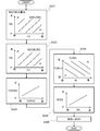
- FIG. 2 is a flowchart showing the operation procedure of the PCV valve 44 during the fuel cut and at the end of the fuel cut, which is carried out by the control device 13. The process shown in the flowchart of FIG. 2 is periodically executed by the control device 13.
- the control device 13 performs a process of calculating the blow-by gas retention amount BGR in step S101.
- the control device 13 applies the blow-by gas staying in each of the intake collector portion 2b, the first blow-by gas recirculation passage 43, and the crankcase 42 to the load of the internal combustion engine 1 and the outside temperature TO. It is estimated based on the closing time of the PCV valve 44 (in other words, the duration of fuel cut), the oil temperature TL, and the integrated mileage ML.
- the control device 13 determines the fuel cut flag fFCUT in step S102.
- the fuel cut flag fFCUT is a flag in which "1" is set when the fuel cut is performed and "0" is set when the fuel cut is not performed.
- the recovery experience flag fFCUTRE is a flag that is set to "1" when fuel injection is restarted from the fuel cut state, and is cleared to "0" at the next fuel cut and when the ignition switch is turned off, for example.
- the delay time DTPCV (DTPCV ⁇ 0 sec) until the operation in the valve opening direction of 44 is started is calculated.
- step S105 the control device 13 calculates the delay time DTPCV based on the blow-by gas retention amount BGR and the intake pressure PB (or intake air flow rate QAR).
- the intake pressure PB and the intake air flow rate QAR are state quantities representing the load of the internal combustion engine 1, and the control device 13 calculates the delay time DTPCV based on the blow-by gas retention amount BGR and the engine load in step S105. ..
- the control device 13 sets the delay time DTPCV longer as the blow-by gas retention amount BGR increases, and the lower the intake pressure PB (or the smaller the intake air flow rate QAR), that is, the more unstable the combustion. Set the delay time DTPCV longer. That is, the control device 13 operates the PCV valve 44 in the valve opening direction to set the delay time DTPCV to a longer time and inject fuel as the condition is such that the amount of blow-by gas flowing into the combustion chamber 10 increases.
- the delay time which is the time from the restart of the PCV valve 44 to the start of the operation of the PCV valve 44 in the valve opening direction, is increased.
- the combustion in the combustion chamber 10 is unstable, and when the blow-by gas flows into the combustion chamber 10 in a state where the combustion is unstable, the emission amount of the particulate substance increases. Therefore, when the amount of blow-by gas flowing into the combustion chamber 10 is increased by operating the PCV valve 44 in the valve opening direction, the elapsed time from the restart of injection is longer and the combustion becomes more stable before the PCV.
- the control device 13 sets the delay time DTPCV so as to start the valve opening operation of the valve 44.
- step S105 the control device 13 proceeds to step S106 and determines whether or not the elapsed time from restarting fuel injection based on the end of the fuel cut has reached the delay time DTPCV. If the elapsed time from the restart of fuel injection has not reached the delay time DTPCV, the control device 13 proceeds to step S107 and keeps the PCV valve 44 fully closed during the fuel cut.
- step S106 the control device 13 proceeds from step S106 to step S108, and operates the PCV valve 44 from the fully closed direction to the valve opening direction to gradually increase the opening degree.
- step S108 the control device 13 opens the PCV valve 44 in the valve opening direction from the fully closed position during fuel cut based on the blow-by gas retention amount BGR and the intake air pressure PB (or intake air flow rate QAR). set a goal.
- the control device 13 sets the opening target of the PCV valve 44 to a lower opening as the blow-by gas retention amount BGR increases, delays the increase in the opening degree of the PCV valve 44, and reduces the blow-by gas retention amount BGR, that is, the retention.
- the opening target of the PCV valve 44 is increased in accordance with the progress of the blow-by gas combustion process.
- the control device 13 sets the opening target of the PCV valve 44 to a low opening and opens the PCV valve 44. Delay the increase in degree. That is, the control device 13 controls the response in the operation of the PCV valve 44 in the valve opening direction, in other words, the valve opening speed of the PCV valve 44, based on the blow-by gas retention amount BGR and the engine load.
- the control device 13 sets the opening amount of the PCV valve 44 per unit time according to the blow-by gas retention amount BGR when the PCV valve 44 is opened, and opens the PCV valve 44 until fully opened according to the opening amount. be able to.
- the control device 13 controls the opening degree of the PCV valve 44 based on the opening degree target set in the step S108.
- the control device 13 starts the operation of the PCV valve 44 in the valve opening direction based on the end of the fuel cut, the larger the blow-by gas retention amount BGR is, the later the response of the operation in the valve opening direction is delayed.
- FIG. 3 is a flowchart showing a calculation process of the blow-by gas retention amount BGR in step S101 of the flowchart of FIG.
- the control device 13 estimates the amount of blow-by gas that is returned to the upstream of the electronically controlled throttle device 8 in the high load region and stays in the intake collector unit 2b. Specifically, the control device 13 sets the instantaneous value ⁇ INCOBG (in other words, the increase in the amount of retention per unit time) of the blow-by gas staying in the intake collector unit 2b as the intake pressure PB (or intake air flow rate QAR) and.
- the blow-by gas retention amount INCOBLG in the intake collector section 2b is obtained by estimating based on the outside air temperature TO and integrating the estimated instantaneous value ⁇ INCOBG.
- step S201 the control device 13 increases the instantaneous value ⁇ INCOBG of the retention amount of blow-by gas as the intake pressure PB is higher, in other words, the engine load is higher and the blow-by gas passes through the intake collector section more.
- the instantaneous value ⁇ INCOBG of the blow-by gas retention amount is estimated more as the outside air temperature TO is lower and the blow-by gas is less likely to vaporize.
- the control device 13 integrates the instantaneous value ⁇ INCOBG of the blow-by gas retention amount estimated based on the intake pressure PB (or intake air flow rate QAR) and the outside air temperature TO to obtain the blow-by gas retention amount INCOBLG in the intake collector unit 2b. ..
- step S202 in the low load region of the internal combustion engine 1 in which the inside of the crankcase 42 is ventilated with fresh air, the blow-by gas staying in the intake collector portion 2b is reduced by flowing fresh air.
- the amount of decrease and change INCOBLRG is estimated based on the intake pressure PB (or intake air flow rate QAR) and the outside air temperature TO.
- the control device 13 sets the decrease change amount INCOBLRG larger as the intake pressure PB (in other words, the engine load) is higher, and sets the decrease change amount INCOBLRG larger as the outside air temperature TO is lower.
- the control device 13 sets the result of subtracting the decrease change amount INCOBLRG from the blow-by gas retention amount INCOBLG to the blow-by gas retention amount INCOBG that stays in the final intake collector unit 2b.
- step S203 the control device 13 sets the blow-by gas retention amount FGPBG remaining in the first blow-by gas recirculation passage 43 to the closing time TCPCV of the PCV valve 44, that is, the PCV valve 44 is fully closed when the fuel is cut. Estimate based on the time held (in other words, the duration of the fuel cut). In the control device 13, the longer the closing time TCPCV of the PCV valve 44, that is, the longer the time during which the release of blow-by gas to the intake passage is blocked, the longer the amount of blow-by gas retained in the first blow-by gas recirculation passage 43. Estimate more FGPBG.
- step S204 the control device 13 estimates the blow-by gas retention amount CCBG retained in the crankcase 42 based on the oil temperature TL and the closing time TCPCV.
- the control device 13 estimates more blow-by gas retention CCBG that stays in the crankcase 42 as the oil temperature TL increases, and estimates more blow-by gas retention CCBG that stays in the crankcase 42 as the closing time TCPCV is longer. ..
- step S205 the control device 13 estimates the amount of increase in blow-by gas BGIA due to deterioration of the piston ring based on the integrated mileage ML of the vehicle.
- step S205 the control device 13 calculates the amount by which the amount of oil dilution increases due to the deterioration of the sealing performance due to the deterioration of the piston ring, and the amount of blow-by gas increases as compared with the case where the piston ring is new.
- the control device 13 sets a larger amount of increase in blow-by gas BGIA as the cumulative mileage ML of the vehicle increases.
- the control device 13 can calculate a correction value for increasing and correcting the blow-by gas retention amount according to the deterioration of the sealing performance due to the deterioration of the piston ring. Further, the control device 13 can set the increase amount BGIA of the blow-by gas based on, for example, the integrated operation time of the internal combustion engine 1 instead of the integrated mileage ML.
- step S201-step S205 the control device 13 has blow-by gas retention INCOBG in the intake collector portion 2b, blow-by gas retention FGPBG in the first blow-by gas recirculation passage 43, and blow-by gas retention in the crankcase 42.
- step S206 these are summed up to obtain the blow-by gas retention amount BGR (in other words, an estimated value of the blow-by gas retention amount).
- the control device 13 calculates the delay time DTPCV in step S105 of the flowchart of FIG. 2 based on the blow-by gas retention amount BGR obtained in step S206, and the opening target of the PCV valve 44 in step S108 of the flowchart of FIG. Is calculated.
- FIG. 4 shows changes in the opening degree of the PCV valve 44 and changes in the amount of blow-by gas released from the PCV valve 44 when the control device 13 controls the opening degree of the PCV valve 44 shown in the flowchart of FIG. It is an example time chart.
- the control device 13 stops the fuel injection by the fuel injection device 5 and operates the PCV valve 44 in the valve closing direction to close the PCV valve 44 until it is fully closed.
- the control device 13 restarts the fuel injection by the fuel injection device 5, but the PCV valve 44 sets the fuel cut. Keep it fully closed while continuing.
- the control device 13 sets the delay time DTPCV from the restart of fuel injection (time t12) to the start of the valve opening operation of the PCV valve 44, based on the blow-by gas retention amount BGR and the engine load.
- the control device 13 uses the PCV valve 44.
- the operation in the valve opening direction of is started.
- the control device 13 gradually opens the PCV valve 44 from the time t13 to the time t14 so as to match the decrease in the blow-by gas retention amount BGR. Increase the degree.
- the control device 13 discharges the amount of blow-by gas flowing into the combustion chamber 10 when operating in the valve opening direction from the fully closed state during fuel cutting to discharge particulate matter. Adjust the amount to an amount that can be suppressed within the allowable range, and gradually reduce the amount of blow-by gas retention. Therefore, when the opening degree of the PCV valve 44 is set to fully closed during the fuel cut and the PCV valve 44 is operated in the valve opening direction based on the end of the fuel cut, the amount of particulate matter discharged increases or the internal combustion engine It is possible to prevent the output torque of the engine 1 from suddenly changing.
- the control device 13 sets the delay time from the establishment of the fuel cut start condition to the actual start of the fuel cut longer as the blow-by gas retention amount increases, and burns the blow-by gas during the delay time. It is possible to suppress the formation of particulate matter after the start of fuel cutting.
- FIG. 5 is a flowchart showing the procedure of the process of delaying the start of the fuel cut.
- the control device 13 periodically executes the process shown in the flowchart of FIG. First, the control device 13 performs an estimation calculation of the blow-by gas retention amount BGR in step S301.
- the calculation process of the blow-by gas retention amount BGR in step S301 is performed according to the flowchart of FIG. 3 described above.
- the control device 13 proceeds to step S302 to determine the fuel cut flag fFCUT.
- the fuel cut flag fFCUT is a flag in which "1" is set during fuel cut and "0" is set when fuel injection is being performed.
- step S303 the control device 13 proceeds to step S303 when the fuel cut flag fFCUT is set to "1", and ends this routine when the fuel cut flag fFCUT is set to "0".
- step S303 the control device 13 sets the delay time DTFC (DTFC ⁇ 0 sec) from the establishment of the fuel cut start condition to the start of the fuel cut to a longer time as the blow-by gas retention amount BGR increases.
- step S304 the control device 13 determines whether or not the delay time DTFC has elapsed from the establishment of the fuel cut start condition. Then, when the elapsed time from the time when the fuel cut start condition is satisfied is shorter than the delay time DTFC, the control device 13 proceeds to step S305 to continue fuel injection by the fuel injection device 5 and blow-by gas amount (in other words). If so, the opening degree of the PCV valve 44 is controlled according to the engine load).
- step S304 when the control device 13 determines in step S304 that the delay time DTFC has elapsed from the establishment of the fuel cut start condition, the control device 13 proceeds to step S306 and starts the fuel cut for stopping the fuel injection by the fuel injection device 5.
- the fuel cut starts when the fuel cut is performed in a state where a large amount of blow-by gas stays due to deceleration from high load operation. It is possible to proceed with the combustion process of blow-by gas within the delay time of the above, and to cut the fuel after the amount of retention of blow-by gas is sufficiently reduced. As a result, it is possible to prevent a large amount of blow-by gas from flowing into the combustion chamber 10 after the start of fuel cutting to generate particulate matter.
- the control device 13 is operated in the valve opening direction of the PCV valve 44 according to the blow-by gas retention amount BGR when the fuel injection is restarted from the fuel cut state shown in the flowchart of FIG. 2, and the flowchart of FIG. 5 is shown. It is possible to carry out the delay processing for starting the fuel cut according to the blow-by gas retention amount BGR shown in 1. Further, the control device 13 can perform the fuel cut start delay process shown in the flowchart of FIG. 5 without controlling the opening degree of the PCV valve 44 at the time of restarting the fuel injection shown in the flowchart of FIG. .. When the control device 13 performs the delay process for starting the fuel cut shown in the flowchart of FIG.
- the PCV valve 44 of the gas recirculation device 41 is not limited to the electronically controlled valve device, and a mechanical PCV valve that operates at a differential pressure can be adopted.
- FIG. 6 is a time chart illustrating changes in the blow-by gas retention amount BGR and the like when the delay process for starting the fuel cut shown in the flowchart of FIG. 5 is performed.
- the internal combustion engine 1 near time t21, the internal combustion engine 1 is operated with a high load in which a large amount of blow-by gas is generated, that is, a high load in which the intake pressure becomes near atmospheric pressure, and at time t22 due to deceleration from the high load operation.
- the fuel cut start condition is satisfied.
- the control device 13 does not start the fuel cut from the time when the fuel cut start condition is satisfied, but sets the delay time DTFC based on the blow-by gas retention amount BGR, and when the fuel cut start condition is satisfied.
- the fuel cut is started at the time t23 when the delay time DTFC has elapsed from. That is, from the time t22 to the time t23 when the fuel cut start condition is satisfied, the fuel cut condition is satisfied, but the control device 13 continues the fuel injection by the fuel injection device 5.
- Blow-by gas combustion processing is performed in the fuel injection continuation section (in other words, within the delay time DTFC) from time t22 to time t23 when the fuel cut start condition is satisfied, and the control device 13 controls the blow-by gas retention amount.
- the fuel cut is started at time t23, which is the time when the BGR drops to a predetermined amount.
- the delay time DTFC is set based on the time required to reduce the blow-by gas retention amount BGR when the fuel cut start condition is satisfied to a predetermined amount in the combustion process.
- control device 13 Since the control device 13 starts the fuel cut after the blow-by gas retention amount BGR is less than when the fuel cut start condition is satisfied, the amount of blow-by gas flowing into the combustion chamber 10 during the fuel cut is reduced, and the fuel cut Compared with the case where the fuel cut is started when the start condition is satisfied, the formation of particulate matter can be suppressed.
- the control device 13 When the control device 13 performs the fuel cut start delay process shown in the flowchart of FIG. 5, the control device 13 minimizes the fuel injection amount by the fuel injection device 5 within the delay time DTFC from the time when the fuel cut start condition is satisfied.
- the injection amount can be set (see step S305).
- the minimum injection amount is the lower limit of the fuel amount range that can be injected by one injection, and the fuel amount range that can be injected by one injection is the amount of fuel that is proportional to the injection time of the fuel injection device 5. Is the range to be injected. That is, the minimum injection amount is the minimum value of the fuel injection amount that can be controlled by the control device 13.
- the control device 13 sets the fuel injection amount by the fuel injection device 5 to the minimum injection amount within the delay time DTFC from the time when the fuel cut start condition is satisfied, and continues the fuel injection.
- the fuel injection amount by the fuel injection device 5 is set to the minimum injection amount while the start of the fuel cut is delayed, so that the increase in fuel consumption due to the delay in the start of the fuel cut is minimized. Therefore, deterioration of fuel efficiency can be suppressed.
- FIG. 7 is a time chart illustrating changes in the fuel injection amount when the fuel injection amount by the fuel injection device 5 is set to the minimum injection amount in the delay time DTFC.
- the control device 13 delays the start of the fuel cut by the delay time DTFC from the establishment of the fuel cut start condition at the time t31, and starts the fuel cut at the time t32 when the delay time DTFC has elapsed.
- the control device 13 sets the fuel injection amount by the fuel injection device 5 to the minimum injection amount, and from the time t32, the fuel injection amount by the fuel injection device 5 is set. Set to zero and shift to the fuel cut state.
- the control device 13 does not operate the PCV valve 44 in the valve opening direction after the delay time DTPCV has elapsed. From the time when fuel injection is restarted, the PCV valve 44 can be operated little by little in the valve opening direction at an operation speed corresponding to the blow-by gas retention amount BGR. Further, in the valve closing control of the PCV valve 44 during the fuel cut, the first blow-by gas recirculation passage 43 is not completely shielded, and an opening to the extent that a predetermined leakage flow rate is generated can be provided.
- the direction of opening the PCV valve 44 is determined depending on the condition for restarting fuel injection from the fuel cut, that is, whether the fuel injection is restarted by lowering the engine speed or the fuel injection is restarted by depressing the accelerator pedal.
- the response delay of the operation can be set individually.
- the control device 13 moves the PCV valve 44 in the valve opening direction based on the emission amount of the particulate matter detected by the sensor. It is possible to modify the operation response delay setting and the fuel cut start delay time setting.
Landscapes
- Engineering & Computer Science (AREA)
- Mechanical Engineering (AREA)
- General Engineering & Computer Science (AREA)
- Chemical & Material Sciences (AREA)
- Combustion & Propulsion (AREA)
- Lubrication Details And Ventilation Of Internal Combustion Engines (AREA)
- Electrical Control Of Air Or Fuel Supplied To Internal-Combustion Engine (AREA)
Abstract
本発明に係る内燃機関の制御装置及び制御方法は、内燃機関における燃料カットの開始に基づいてブローバイガス還流通路に設けられるPCVバルブを閉弁方向に操作し、燃料カットの終了に基づきPCVバルブを開弁方向に操作し、燃料カットの終了に基づくPCVバルブの開弁方向への操作の応答をブローバイガスの滞留量が多いときほどより遅くする。これにより、燃料カットの終了に基づき燃焼室へのブローバイガスの供給を再開するときに、粒子状物質の排出量が増加することや内燃機関の出力トルクが急変することを抑止できる。
Description
本発明は、ブローバイガス還流通路と、前記ブローバイガス還流通路に設けた電制バルブ装置とを備えた車両用の内燃機関を制御するための内燃機関の制御装置及び制御方法に関する。
特許文献1が開示する内燃機関の吸気制御装置は、外部から燃焼室に供給される新気の流量を調整するスロットルバルブと、機関本体から吸気通路に供給されるブローバイガスを含むPCV(Positive Crankcase Ventilation)ガスの流量を調整するPCVバルブとを備え、燃料カットが開始されることに基づいて、PCVバルブを閉弁方向に操作するとともにスロットルバルブを開弁方向に操作する制御手段を備える。
ところで、燃料カット中にPCVバルブを全閉に保持し、燃料カットの終了に基づきPCVバルブを開弁方向に操作する場合、燃料カットの終了時点でブローバイガス還流通路などに滞留していたブローバイガスが燃焼室に流入し、排気中の粒子状物質(Particulate Matter)が増加したり、内燃機関の出力トルクが急変したりする場合があった。
本発明は、従来の実情に鑑みてなされたものであり、その目的は、燃料カットの終了に基づき燃焼室へのブローバイガスの供給を再開するときに、内燃機関からの粒子状物質の排出量が増加することや内燃機関の出力トルクが急変することを抑止できる、内燃機関の制御装置及び制御方法を提供することにある。
そのため、本発明に係る内燃機関の制御装置及び制御方法は、その一態様として、内燃機関における燃料カットの開始に基づいて、ブローバイガス還流通路に設けられる電制バルブ装置を閉弁方向に操作し、前記燃料カットの終了に基づき前記電制バルブ装置を開弁方向に操作し、前記燃料カットの終了に基づく前記電制バルブ装置の開弁方向への操作の応答を、ブローバイガスの滞留量が多いときほどより遅くする。
上記発明によると、燃料カットの終了に基づき燃焼室へのブローバイガスの供給を再開するときに、内燃機関からの粒子状物質の排出量が増加することや内燃機関の出力トルクが急変することを抑止できる。
以下に本発明の実施の形態を説明する。
図1は、本発明に係る内燃機関の制御装置及び制御方法を適用する車両用の内燃機関の一態様を示す図である。
図1に示す内燃機関1は、車両の動力源として使用される火花点火ガソリン機関であり、機関本体1aに点火装置4や燃料噴射装置5などを備える。
図1は、本発明に係る内燃機関の制御装置及び制御方法を適用する車両用の内燃機関の一態様を示す図である。
図1に示す内燃機関1は、車両の動力源として使用される火花点火ガソリン機関であり、機関本体1aに点火装置4や燃料噴射装置5などを備える。
燃料噴射装置5は、インレットマニホールド2aに配置され、インレットマニホールド2a内に燃料であるガソリンを噴射する。
内燃機関1の吸入空気は、エアークリーナ7、電制スロットル装置8、及び吸気バルブ19を経て、燃料噴射装置5が噴射する燃料とともに燃焼室10に流入する。
内燃機関1の吸入空気は、エアークリーナ7、電制スロットル装置8、及び吸気バルブ19を経て、燃料噴射装置5が噴射する燃料とともに燃焼室10に流入する。
電制スロットル装置8は、スロットルモータ8bでスロットルバルブ8aを開閉する装置であって、内燃機関1の吸入空気量を調整する。電制スロットル装置8は、スロットル開度TPSに応じた信号を出力するスロットル開度センサ8cを備える。
また、排気浄化触媒装置12は、排気ダクト3aに配置され、三元触媒などによって内燃機関1の排気を浄化する。
また、排気浄化触媒装置12は、排気ダクト3aに配置され、三元触媒などによって内燃機関1の排気を浄化する。
回転数検出装置6は、リングギア14の突起を検出することで、クランクシャフト14Aの所定回転角毎に回転角NEの信号を出力する。
流量検出装置9は、電制スロットル装置8の上流側に配置され、内燃機関1の吸入空気流量QARに応じた信号を出力する。
流量検出装置9は、電制スロットル装置8の上流側に配置され、内燃機関1の吸入空気流量QARに応じた信号を出力する。
油温センサ11は、内燃機関1の潤滑油の温度である油温TLに応じた信号を出力する。
外気温センサ15は、外気温TO、換言すれば、車両外部の気温に応じた信号を出力する。
外気温センサ15は、外気温TO、換言すれば、車両外部の気温に応じた信号を出力する。
電子式の走行距離計16は、車両の積算走行距離を計測し、積算走行距離MLに応じた信号を出力する。
吸気圧センサ17は、電制スロットル装置8の下流の圧力である吸気圧PBに応じた信号を出力する。
吸気圧センサ17は、電制スロットル装置8の下流の圧力である吸気圧PBに応じた信号を出力する。
マイクロコンピュータを備えた電子制御装置である制御装置13は、スロットル開度TPS、吸入空気流量QAR、回転角NE、油温TL、外気温TO、積算走行距離MLなどの検出信号を取り込む。
そして、制御装置13は、取り込んだセンサ検出信号に基づき燃料噴射パルス幅TI[ms]及び噴射タイミングを演算し、噴射タイミングにおいて燃料噴射パルス幅TIに応じた開弁指令信号を燃料噴射装置5に出力して、燃料噴射装置5による燃料噴射量及び噴射タイミングを制御する機能をソフトウェアとして備える。
そして、制御装置13は、取り込んだセンサ検出信号に基づき燃料噴射パルス幅TI[ms]及び噴射タイミングを演算し、噴射タイミングにおいて燃料噴射パルス幅TIに応じた開弁指令信号を燃料噴射装置5に出力して、燃料噴射装置5による燃料噴射量及び噴射タイミングを制御する機能をソフトウェアとして備える。
また、制御装置13は、内燃機関1の減速運転状態において燃料噴射装置5による燃料噴射を一時的に停止する燃料カットを実施する。
例えば、制御装置13は、運転者がアクセルペダルから足を離し、かつ、機関回転速度が第1閾値よりも高いときに、燃料カット開始の条件成立を判定して燃料噴射装置5による燃料噴射を停止させる。
例えば、制御装置13は、運転者がアクセルペダルから足を離し、かつ、機関回転速度が第1閾値よりも高いときに、燃料カット開始の条件成立を判定して燃料噴射装置5による燃料噴射を停止させる。
そして、制御装置13は、燃料噴射装置5による燃料噴射を停止させている状態で、機関回転速度が第2閾値(第2閾値<第1閾値)を下回ると燃料噴射装置5による燃料噴射を再開させ、また、運転者がアクセルペダルを踏み込んだときも燃料噴射装置5による燃料噴射を再開させる。
更に、制御装置13は、点火装置4、電制スロットル装置8の指令信号を生成して出力し、点火装置4の点火時期、スロットルバルブ8aの開度などを制御して、内燃機関1の運転を制御する。
更に、制御装置13は、点火装置4、電制スロットル装置8の指令信号を生成して出力し、点火装置4の点火時期、スロットルバルブ8aの開度などを制御して、内燃機関1の運転を制御する。
制御装置13は、各種センサの計測結果や各種装置に出力する操作量などのデータの入出力を行うために、アナログ入力回路20、A/D変換回路21、デジタル入力回路22、出力回路23及びI/O回路24を備える。
また、制御装置13は、データの演算処理を行うために、MPU(Microprocessor Unit)26、ROM(Read Only Memory)27、RAM(Random Access Memory)28を含むマイクロコンピュータ31を備える。
また、制御装置13は、データの演算処理を行うために、MPU(Microprocessor Unit)26、ROM(Read Only Memory)27、RAM(Random Access Memory)28を含むマイクロコンピュータ31を備える。
アナログ入力回路20は、吸入空気流量QAR、スロットル開度TPS、油温TL、外気温TO、吸気圧PBなどに関するアナログ信号を取得し、取得したアナログ信号をA/D変換回路21に供給する。
A/D変換回路21は、取得したアナログ信号をデジタル信号に変換し、バス25上に出力する。
A/D変換回路21は、取得したアナログ信号をデジタル信号に変換し、バス25上に出力する。
また、デジタル入力回路22は、回転角NE、積算走行距離MLなどに関するデジタル信号を取得し、取得したデジタル信号を、I/O回路24を介してバス25上に出力する。
バス25には、MPU26、ROM27、RAM28、タイマ/カウンタ29などが接続される。そして、MPU26、ROM27、RAM28は、バス25を介してデータの授受を行う。
バス25には、MPU26、ROM27、RAM28、タイマ/カウンタ29などが接続される。そして、MPU26、ROM27、RAM28は、バス25を介してデータの授受を行う。
クロックジェネレータ30は、MPU26にクロック信号を供給し、MPU26は、クロック信号に同期して様々な演算や処理を実行する。
ROM27は、例えば、データの消去と書き換えが可能なEEPROM(Electrically Erasable Programmable Read-Only Memory)で構成され、制御装置13を動作させるためのプログラム、設定データ及び初期値などを記憶する。
ROM27が記憶する情報は、バス25を介してRAM28及びMPU26に読み込まれる。
ROM27は、例えば、データの消去と書き換えが可能なEEPROM(Electrically Erasable Programmable Read-Only Memory)で構成され、制御装置13を動作させるためのプログラム、設定データ及び初期値などを記憶する。
ROM27が記憶する情報は、バス25を介してRAM28及びMPU26に読み込まれる。
RAM28は、MPU26による演算結果や処理結果を一時的に記憶する作業領域として用いられる。
なお、タイマ/カウンタ29は、時間の測定や様々な回数の測定などに用いられる。
MPU26による演算結果や処理結果は、バス25上に出力された後、I/O回路24を介して出力回路23から点火装置4、燃料噴射装置5、電制スロットル装置8などに供給される。
なお、タイマ/カウンタ29は、時間の測定や様々な回数の測定などに用いられる。
MPU26による演算結果や処理結果は、バス25上に出力された後、I/O回路24を介して出力回路23から点火装置4、燃料噴射装置5、電制スロットル装置8などに供給される。
また、内燃機関1は、ブローバイガス還流装置41を備える。
ブローバイガス還流装置41は、内燃機関1の燃焼室10内から潤滑油を貯留するクランクケース42内に漏出した未燃燃料のうちの気化燃料を含むブローバイガスを内燃機関1の吸気通路に戻す装置である。
ブローバイガス還流装置41は、内燃機関1の燃焼室10内から潤滑油を貯留するクランクケース42内に漏出した未燃燃料のうちの気化燃料を含むブローバイガスを内燃機関1の吸気通路に戻す装置である。
ブローバイガス還流装置41は、クランクケース42内と電制スロットル装置8下流の吸気コレクタ部2b内とを連通させる第1ブローバイガス還流通路43、電制スロットル装置8よりも上流の吸気通路とクランクケース42とを連通する第2ブローバイガス還流通路45、及び、第1ブローバイガス還流通路43に設けられたPCVバルブ44を備える。
PCVバルブ44は、制御装置13によって駆動制御される電動モータなどのアクチュエータを有し、アクチュエータによって開閉駆動されて開度が調整される、電制バルブ装置である。
PCVバルブ44は、制御装置13によって駆動制御される電動モータなどのアクチュエータを有し、アクチュエータによって開閉駆動されて開度が調整される、電制バルブ装置である。
なお、クランクケース42の下部に設けられたオイルパンに、内燃機関1の潤滑油が溜められる。
上記のブローバイガス還流装置41において、内燃機関1の低負荷域で吸気圧が負圧になるとき、制御装置13は、PCVバルブ44を開弁操作する。そして、クランクケース42内のブローバイガスは、電制スロットル装置8の下流とクランクケース42内との間に生じる差圧によって、第1ブローバイガス還流通路43を介して電制スロットル装置8の下流に供給され、燃焼室10内で燃焼処理される。
上記のブローバイガス還流装置41において、内燃機関1の低負荷域で吸気圧が負圧になるとき、制御装置13は、PCVバルブ44を開弁操作する。そして、クランクケース42内のブローバイガスは、電制スロットル装置8の下流とクランクケース42内との間に生じる差圧によって、第1ブローバイガス還流通路43を介して電制スロットル装置8の下流に供給され、燃焼室10内で燃焼処理される。
また、内燃機関1の低負荷域では、新気が電制スロットル装置8の上流から第2ブローバイガス還流通路45を介してクランクケース42内へ導入されてクランクケース42内が換気される。
一方、内燃機関1の高負荷域で吸気圧が大気圧付近になるとき、制御装置13はPCVバルブ44を閉弁操作し、クランクケース42内のブローバイガスは、第2ブローバイガス還流通路45を介して電制スロットル装置8の上流に供給されて、燃焼室10内で燃焼処理される。
一方、内燃機関1の高負荷域で吸気圧が大気圧付近になるとき、制御装置13はPCVバルブ44を閉弁操作し、クランクケース42内のブローバイガスは、第2ブローバイガス還流通路45を介して電制スロットル装置8の上流に供給されて、燃焼室10内で燃焼処理される。
以下では、制御装置13によるPCVバルブ44の開度制御を詳述する。
制御装置13は、燃料カット中において、電制スロットル装置8を開弁操作して燃焼室10の負圧を低下させ、燃焼室10内に吸い込まれる潤滑油の量を抑制するとともに、PCVバルブ44を全閉に操作する。
これにより、電制スロットル装置8の開弁操作によって燃焼室10に供給される新気の量が増量される一方で、PCVバルブ44の閉弁操作によって燃焼室10に供給されるブローバイガスの量は減量される。したがって、燃料カット実行中に燃焼室10に供給されるガス量が要求量から乖離することが抑制される。
制御装置13は、燃料カット中において、電制スロットル装置8を開弁操作して燃焼室10の負圧を低下させ、燃焼室10内に吸い込まれる潤滑油の量を抑制するとともに、PCVバルブ44を全閉に操作する。
これにより、電制スロットル装置8の開弁操作によって燃焼室10に供給される新気の量が増量される一方で、PCVバルブ44の閉弁操作によって燃焼室10に供給されるブローバイガスの量は減量される。したがって、燃料カット実行中に燃焼室10に供給されるガス量が要求量から乖離することが抑制される。
また、制御装置13は、燃料カットの終了、換言すれば、燃料噴射の再開に伴い、PCVバルブ44を開弁方向に操作するときに、PCVバルブ44の開弁操作の応答を、第1ブローバイガス還流通路43などにおけるブローバイガスの滞留量が多いときほどより遅くする。
これにより、PCVバルブ44の全閉状態で第1ブローバイガス還流通路43などに滞留していたブローバイガスが、PCVバルブ44の開弁操作に伴って燃焼室10内に多く流入して、粒子状物質の排出量が増加したり、内燃機関1の出力トルクの急変が発生したりすることを抑制する。
これにより、PCVバルブ44の全閉状態で第1ブローバイガス還流通路43などに滞留していたブローバイガスが、PCVバルブ44の開弁操作に伴って燃焼室10内に多く流入して、粒子状物質の排出量が増加したり、内燃機関1の出力トルクの急変が発生したりすることを抑制する。
なお、ブローバイガスの滞留は、内燃機関1の高負荷時に第2ブローバイガス還流通路45を介して電制スロットル装置8の上流に還流されて吸気コレクタ部2bに滞留する分、高負荷時にPCVバルブ44が閉じられて第1ブローバイガス還流通路43に滞留する分、更に、PCVバルブ44が閉操作される燃料カット中にクランクケース42内に滞留する分などを含む。
図2は、制御装置13が実施する、燃料カット中及び燃料カット終了時におけるPCVバルブ44の操作手順を示すフローチャートである。
なお、図2のフローチャートに示す処理は、制御装置13により周期的に実施される。
なお、図2のフローチャートに示す処理は、制御装置13により周期的に実施される。
制御装置13は、まず、ステップS101で、ブローバイガス滞留量BGRを算出する処理を実施する。
制御装置13は、後で詳細に説明するように、吸気コレクタ部2b、第1ブローバイガス還流通路43、及びクランクケース42のそれぞれに滞留するブローバイガスを、内燃機関1の負荷、外気温TO、PCVバルブ44の閉時間(換言すれば、燃料カットの継続時間)、油温TL、積算走行距離MLに基づき推定する。
制御装置13は、後で詳細に説明するように、吸気コレクタ部2b、第1ブローバイガス還流通路43、及びクランクケース42のそれぞれに滞留するブローバイガスを、内燃機関1の負荷、外気温TO、PCVバルブ44の閉時間(換言すれば、燃料カットの継続時間)、油温TL、積算走行距離MLに基づき推定する。
次いで、制御装置13は、ステップS102で、燃料カットフラグfFCUTの判別を行う。
燃料カットフラグfFCUTは、燃料カットを実施しているときに「1」がセットされ、燃料カットを実施していないときに「0」がセットされるフラグである。
燃料カットフラグfFCUTは、燃料カットを実施しているときに「1」がセットされ、燃料カットを実施していないときに「0」がセットされるフラグである。
制御装置13は、燃料カットフラグfFCUTに「1」がセットされる燃料カット中であるときは、ステップS103に進んで、PCVバルブ44を閉弁方向に操作して全閉に設定する。
一方、制御装置13は、燃料カットフラグfFCUTが「0」であって燃料カットを実施していないときは、ステップS104に進んで、燃料カットフラグfFCUT=0で、かつ、リカバー経験フラグfFCUTRE=1であるか否かを判断する。
一方、制御装置13は、燃料カットフラグfFCUTが「0」であって燃料カットを実施していないときは、ステップS104に進んで、燃料カットフラグfFCUT=0で、かつ、リカバー経験フラグfFCUTRE=1であるか否かを判断する。
リカバー経験フラグfFCUTREは、燃料カット状態から燃料噴射を再開させたときに「1」がセットされ、例えば、次の燃料カット時及びイグニッションスイッチのオフ時に「0」にクリアされるフラグである。
制御装置13は、燃料カットフラグfFCUT=0で、かつ、リカバー経験フラグfFCUTRE=1であるとき、つまり、燃料カットから燃料噴射を再開させるときにステップS105に進んで、燃料カットの終了からPCVバルブ44の開弁方向への操作を開始させるまでの遅れ時間DTPCV(DTPCV≧0sec)を演算する。
制御装置13は、燃料カットフラグfFCUT=0で、かつ、リカバー経験フラグfFCUTRE=1であるとき、つまり、燃料カットから燃料噴射を再開させるときにステップS105に進んで、燃料カットの終了からPCVバルブ44の開弁方向への操作を開始させるまでの遅れ時間DTPCV(DTPCV≧0sec)を演算する。
制御装置13は、ステップS105で、ブローバイガス滞留量BGR及び吸気圧PB(又は吸入空気流量QAR)に基づき遅れ時間DTPCVを演算する。
なお、吸気圧PB、吸入空気流量QARは、内燃機関1の負荷を代表する状態量であり、制御装置13は、ステップS105で、ブローバイガス滞留量BGR及び機関負荷に基づき遅れ時間DTPCVを演算する。
なお、吸気圧PB、吸入空気流量QARは、内燃機関1の負荷を代表する状態量であり、制御装置13は、ステップS105で、ブローバイガス滞留量BGR及び機関負荷に基づき遅れ時間DTPCVを演算する。
制御装置13は、ブローバイガス滞留量BGRが多いほど遅れ時間DTPCVをより長く設定し、かつ、吸気圧PBが低い(又は吸入空気流量QARが少ない)ほど、つまり、燃焼が不安定なときほど、遅れ時間DTPCVをより長く設定する。
つまり、制御装置13は、PCVバルブ44を開弁方向に操作することで、燃焼室10に流入するブローバイガス量が多くなる条件のときほど、遅れ時間DTPCVをより長い時間に設定し、燃料噴射の再開からPCVバルブ44の開弁方向への操作を開始するまでの時間である遅延時間を長くする。
つまり、制御装置13は、PCVバルブ44を開弁方向に操作することで、燃焼室10に流入するブローバイガス量が多くなる条件のときほど、遅れ時間DTPCVをより長い時間に設定し、燃料噴射の再開からPCVバルブ44の開弁方向への操作を開始するまでの時間である遅延時間を長くする。
燃料カットから燃料噴射を再開させたときは燃焼室10での燃焼が不安定で、燃焼が不安定な状態で燃焼室10にブローバイガスが流入すると、粒子状物質の排出量が増加する。
そこで、PCVバルブ44を開弁方向に操作することで燃焼室10に流入するブローバイガス量が多くなる条件のときほど、噴射再開からの経過時間が長く燃焼がより安定するようになってからPCVバルブ44の開弁操作を開始させるように、制御装置13は、遅れ時間DTPCVを設定する。
そこで、PCVバルブ44を開弁方向に操作することで燃焼室10に流入するブローバイガス量が多くなる条件のときほど、噴射再開からの経過時間が長く燃焼がより安定するようになってからPCVバルブ44の開弁操作を開始させるように、制御装置13は、遅れ時間DTPCVを設定する。
制御装置13は、ステップS105で遅れ時間DTPCVを演算すると、ステップS106に進み、燃料カットの終了に基づき燃料噴射を再開させてからの経過時間が遅れ時間DTPCVに達したか否かを判断する。
燃料噴射の再開からの経過時間が遅れ時間DTPCVに達していない場合、制御装置13は、ステップS107に進み、PCVバルブ44を燃料カット中に引き続き全閉に保持する。
燃料噴射の再開からの経過時間が遅れ時間DTPCVに達していない場合、制御装置13は、ステップS107に進み、PCVバルブ44を燃料カット中に引き続き全閉に保持する。
そして、燃料噴射の再開からの経過時間が遅れ時間DTPCVに達すると、制御装置13は、ステップS106からステップS108に進み、PCVバルブ44を全閉から開弁方向に操作して開度を徐々に増加させるときの開度目標を設定する。
つまり、制御装置13は、燃料カットを開始するときにPCVバルブ44を全閉に制御し、その後、燃料カットの終了からの経過時間が遅れ時間DTPCVに達するまでの間においてPCVバルブ44を全閉に保持し、燃料カットの終了からの経過時間が遅れ時間DTPCVに達してから、PCVバルブ44の開弁方向への操作を開始する。
つまり、制御装置13は、燃料カットを開始するときにPCVバルブ44を全閉に制御し、その後、燃料カットの終了からの経過時間が遅れ時間DTPCVに達するまでの間においてPCVバルブ44を全閉に保持し、燃料カットの終了からの経過時間が遅れ時間DTPCVに達してから、PCVバルブ44の開弁方向への操作を開始する。
制御装置13は、ステップS108で、ブローバイガス滞留量BGR及び吸気圧PB(又は吸入空気流量QAR)に基づき、PCVバルブ44を燃料カット中の全閉位置から開弁方向に操作するときの開度目標を設定する。
制御装置13は、ブローバイガス滞留量BGRが多いほどPCVバルブ44の開度目標を低開度に設定してPCVバルブ44の開度の増加を遅らせ、ブローバイガス滞留量BGRの減少、つまり、滞留していたブローバイガスの燃焼処理の進行に合わせて、PCVバルブ44の開度目標を増大させる。
制御装置13は、ブローバイガス滞留量BGRが多いほどPCVバルブ44の開度目標を低開度に設定してPCVバルブ44の開度の増加を遅らせ、ブローバイガス滞留量BGRの減少、つまり、滞留していたブローバイガスの燃焼処理の進行に合わせて、PCVバルブ44の開度目標を増大させる。
また、制御装置13は、吸気圧PBが低いほど、つまり、負圧が高くブローバイガスが流入し易い場合は、PCVバルブ44の開度目標を低開度に設定して、PCVバルブ44の開度の増加を遅らせる。
つまり、制御装置13は、ブローバイガス滞留量BGR及び機関負荷に基づき、PCVバルブ44の開弁方向への操作における応答、換言すれば、PCVバルブ44の開弁速度を制御する。
ここで、制御装置13は、PCVバルブ44を開くときのブローバイガス滞留量BGRに応じて単位時間当たりのPCVバルブ44の開度量を設定し、係る開度量に応じて全開までPCVバルブ44を開くことができる。
つまり、制御装置13は、ブローバイガス滞留量BGR及び機関負荷に基づき、PCVバルブ44の開弁方向への操作における応答、換言すれば、PCVバルブ44の開弁速度を制御する。
ここで、制御装置13は、PCVバルブ44を開くときのブローバイガス滞留量BGRに応じて単位時間当たりのPCVバルブ44の開度量を設定し、係る開度量に応じて全開までPCVバルブ44を開くことができる。
そして、制御装置13は、次のステップS109で、ステップS108で設定した開度目標に基づきPCVバルブ44の開度を制御する。
このように、制御装置13は、燃料カットの終了に基づきPCVバルブ44の開弁方向への操作を開始するときに、ブローバイガス滞留量BGRが多いほど開弁方向への操作の応答を遅らせる。
このように、制御装置13は、燃料カットの終了に基づきPCVバルブ44の開弁方向への操作を開始するときに、ブローバイガス滞留量BGRが多いほど開弁方向への操作の応答を遅らせる。
これにより、制御装置13が、燃料カットの終了に基づきPCVバルブ44の開弁方向への操作を開始するときに、燃料カットの終了時に第1ブローバイガス還流通路43などに滞留していたブローバイガスが一挙に燃焼室10に流入することが抑止される。
そして、ブローバイガスの燃焼室10への流入量が低く制限される状態で推移することで、粒子状物質の排出量の増加が抑制され、また、内燃機関1の出力トルクの急変が発生することが抑止される。
そして、ブローバイガスの燃焼室10への流入量が低く制限される状態で推移することで、粒子状物質の排出量の増加が抑制され、また、内燃機関1の出力トルクの急変が発生することが抑止される。
図3は、図2のフローチャートのステップS101におけるブローバイガス滞留量BGRの算出処理を示すフローチャートである。
制御装置13は、ステップS201で、高負荷域で電制スロットル装置8の上流に還流されるブローバイガスが、吸気コレクタ部2bに滞留する量を推定する。
詳細には、制御装置13は、吸気コレクタ部2bに滞留するブローバイガスの瞬時値ΔINCOBG(換言すれば、単位時間当たりの滞留量の増加分)を、吸気圧PB(又は吸入空気流量QAR)及び外気温TOに基づき推定し、推定した瞬時値ΔINCOBGを積算することで吸気コレクタ部2bにおけるブローバイガス滞留量INCOBLGを求める。
制御装置13は、ステップS201で、高負荷域で電制スロットル装置8の上流に還流されるブローバイガスが、吸気コレクタ部2bに滞留する量を推定する。
詳細には、制御装置13は、吸気コレクタ部2bに滞留するブローバイガスの瞬時値ΔINCOBG(換言すれば、単位時間当たりの滞留量の増加分)を、吸気圧PB(又は吸入空気流量QAR)及び外気温TOに基づき推定し、推定した瞬時値ΔINCOBGを積算することで吸気コレクタ部2bにおけるブローバイガス滞留量INCOBLGを求める。
制御装置13は、ステップS201で、吸気圧PBが高いほど、換言すれば、機関負荷が高くブローバイガスがより多く吸気コレクタ部を通過するときほど、ブローバイガスの滞留量の瞬時値ΔINCOBGをより多く推定し、また、外気温TOが低くブローバイガスが気化しにくくなるほどブローバイガス滞留量の瞬時値ΔINCOBGをより多く推定する。
そして、制御装置13は、吸気圧PB(又は吸入空気流量QAR)及び外気温TOに基づき推定したブローバイガス滞留量の瞬時値ΔINCOBGを積算して、吸気コレクタ部2bにおけるブローバイガス滞留量INCOBLGを求める。
そして、制御装置13は、吸気圧PB(又は吸入空気流量QAR)及び外気温TOに基づき推定したブローバイガス滞留量の瞬時値ΔINCOBGを積算して、吸気コレクタ部2bにおけるブローバイガス滞留量INCOBLGを求める。
次に、制御装置13は、ステップS202で、クランクケース42内が新気で換気される内燃機関1の低負荷域において、吸気コレクタ部2bに滞留するブローバイガスが新気に流されて減っていく分である減少変化分INCOBLRGを、吸気圧PB(又は吸入空気流量QAR)及び外気温TOに基づき推定する。
ここで、制御装置13は、吸気圧PB(換言すれば、機関負荷)が高いほど減少変化分INCOBLRGを大きく設定し、また、外気温TOが低いほど減少変化分INCOBLRGを大きく設定する。
そして、制御装置13は、ブローバイガス滞留量INCOBLGから減少変化分INCOBLRGを減算した結果を、最終的な吸気コレクタ部2bに滞留するブローバイガス滞留量INCOBGに設定する。
ここで、制御装置13は、吸気圧PB(換言すれば、機関負荷)が高いほど減少変化分INCOBLRGを大きく設定し、また、外気温TOが低いほど減少変化分INCOBLRGを大きく設定する。
そして、制御装置13は、ブローバイガス滞留量INCOBLGから減少変化分INCOBLRGを減算した結果を、最終的な吸気コレクタ部2bに滞留するブローバイガス滞留量INCOBGに設定する。
次いで、制御装置13は、ステップS203で、第1ブローバイガス還流通路43に残留するブローバイガス滞留量FGPBGを、PCVバルブ44の閉時間TCPCV、つまり、燃料カットに伴ってPCVバルブ44を全閉に保持した時間(換言すれば、燃料カットの継続時間)に基づき推定する。
制御装置13は、PCVバルブ44の閉時間TCPCVが長くなるほど、つまり、吸気通路へのブローバイガスの放出が遮断されている時間が長くなるほど、第1ブローバイガス還流通路43に滞留するブローバイガス滞留量FGPBGをより多く推定する。
制御装置13は、PCVバルブ44の閉時間TCPCVが長くなるほど、つまり、吸気通路へのブローバイガスの放出が遮断されている時間が長くなるほど、第1ブローバイガス還流通路43に滞留するブローバイガス滞留量FGPBGをより多く推定する。
更に、制御装置13は、ステップS204で、クランクケース42内に滞留するブローバイガス滞留量CCBGを、油温TL及び閉時間TCPCVに基づき推定する。
制御装置13は、油温TLが高いほどクランクケース42内に滞留するブローバイガス滞留量CCBGを多く推定し、閉時間TCPCVが長いほどクランクケース42内に滞留するブローバイガス滞留量CCBGを多く推定する。
制御装置13は、油温TLが高いほどクランクケース42内に滞留するブローバイガス滞留量CCBGを多く推定し、閉時間TCPCVが長いほどクランクケース42内に滞留するブローバイガス滞留量CCBGを多く推定する。
次いで、制御装置13は、ステップS205で、ピストンリングの劣化によるブローバイガスの増加量BGIAを、車両の積算走行距離MLに基づき推定する。
制御装置13は、ステップS205で、ピストンリングの劣化によるシール性能の低下によってオイル希釈量が増加して、ピストンリングが新品であるときよりもブローバイガス量が増加する分を算出する。
制御装置13は、ステップS205で、ピストンリングの劣化によるシール性能の低下によってオイル希釈量が増加して、ピストンリングが新品であるときよりもブローバイガス量が増加する分を算出する。
一般的に、車両の積算走行距離MLが多くなるほどピストンリングの劣化が進むので、制御装置13は、車両の積算走行距離MLが長くなるほど、ブローバイガスの増加量BGIAをより多く設定する。
なお、制御装置13は、ステップS205で、ピストンリングの劣化によるシール性能の低下に応じてブローバイガス滞留量を増量補正する補正値を算出することができる。また、制御装置13は、積算走行距離MLに代えて、例えば、内燃機関1の積算運転時間などに基づき、ブローバイガスの増加量BGIAを設定することができる。
なお、制御装置13は、ステップS205で、ピストンリングの劣化によるシール性能の低下に応じてブローバイガス滞留量を増量補正する補正値を算出することができる。また、制御装置13は、積算走行距離MLに代えて、例えば、内燃機関1の積算運転時間などに基づき、ブローバイガスの増加量BGIAを設定することができる。
制御装置13は、上記のように、ステップS201-ステップS205で、吸気コレクタ部2bにおけるブローバイガス滞留量INCOBG、第1ブローバイガス還流通路43におけるブローバイガス滞留量FGPBG、クランクケース42内におけるブローバイガス滞留量CCBG、ピストンリングの劣化によるブローバイガスの増加量BGIAを求めると、ステップS206で、これらを総和してブローバイガス滞留量BGR(換言すれば、ブローバイガス滞留量の推定値)を求める。
制御装置13は、ステップS206で求めたブローバイガス滞留量BGRに基づき、図2のフローチャートのステップS105で遅れ時間DTPCVを算出し、また、図2のフローチャートのステップS108でPCVバルブ44の開度目標を算出する。
制御装置13は、ステップS206で求めたブローバイガス滞留量BGRに基づき、図2のフローチャートのステップS105で遅れ時間DTPCVを算出し、また、図2のフローチャートのステップS108でPCVバルブ44の開度目標を算出する。
図4は、図2のフローチャートに示したPCVバルブ44の開度制御を制御装置13が実施するときの、PCVバルブ44の開度変化やPCVバルブ44からのブローバイガスの放出量などの変化を例示するタイムチャートである。
図4の時刻t11で燃料カットの開始の条件が成立し、制御装置13は、燃料噴射装置5による燃料噴射を停止させるとともに、PCVバルブ44を閉弁方向に操作して全閉にまで閉じる。
図4の時刻t11で燃料カットの開始の条件が成立し、制御装置13は、燃料噴射装置5による燃料噴射を停止させるとともに、PCVバルブ44を閉弁方向に操作して全閉にまで閉じる。
図4の時刻t12で、燃料カットの終了条件、換言すれば、燃料噴射の再開条件が成立すると、制御装置13は、燃料噴射装置5による燃料噴射を再開させるが、PCVバルブ44は、燃料カット中に引き続き全閉に保持する。
制御装置13は、ブローバイガス滞留量BGR及び機関負荷に基づき、燃料噴射の再開(時刻t12)からPCVバルブ44の開弁操作を開始するまでの遅れ時間DTPCVを設定する。
制御装置13は、ブローバイガス滞留量BGR及び機関負荷に基づき、燃料噴射の再開(時刻t12)からPCVバルブ44の開弁操作を開始するまでの遅れ時間DTPCVを設定する。
そして、燃料噴射の再開(時刻t12)から遅れ時間DTPCVが経過した時刻t13、つまり、内燃機関1の燃焼がブローバイガス滞留量BGRに見合う安定状態になってから、制御装置13は、PCVバルブ44の開弁方向の操作を開始する。
制御装置13は、PCVバルブ44の開弁方向への操作を時刻t13から開始した後、時刻t13から時刻t14の間で、ブローバイガス滞留量BGRの減少に合わせるように徐々にPCVバルブ44の開度を増加させる。
制御装置13は、PCVバルブ44の開弁方向への操作を時刻t13から開始した後、時刻t13から時刻t14の間で、ブローバイガス滞留量BGRの減少に合わせるように徐々にPCVバルブ44の開度を増加させる。
係るPCVバルブ44の開度制御によれば、制御装置13は、燃料カット中の全閉状態から開弁方向に操作するときに、燃焼室10に流入するブローバイガス量を、粒子状物質の排出量を許容範囲内に抑制できる量に調整して、ブローバイガス滞留量を徐々に減らす。
したがって、PCVバルブ44の開度を燃料カット中に全閉に設定し、燃料カットの終了に基づきPCVバルブ44を開弁方向に操作するときに、粒子状物質の排出量が増加したり、内燃機関1の出力トルクが急変したりすることを抑制できる。
したがって、PCVバルブ44の開度を燃料カット中に全閉に設定し、燃料カットの終了に基づきPCVバルブ44を開弁方向に操作するときに、粒子状物質の排出量が増加したり、内燃機関1の出力トルクが急変したりすることを抑制できる。
ところで、内燃機関1が、ブローバイガスが多く生じる高負荷運転から減速され、制御装置13が燃料カットを開始すると、多量のブローバイガスが吸気コレクタ部2bに滞留している状態で燃料カットが開始されることになる。
この場合、燃料カット開始後に吸気コレクタ部2bから新気で流され燃焼室10に流入するブローバイガスは、燃料カット中であるため燃焼処理されず、粒子状物質が生成される場合がある。
そこで、制御装置13は、燃料カットの開始条件が成立してから実際に燃料カットを開始するまでの遅れ時間をブローバイガス滞留量が多いほど長く設定し、係る遅れ時間の間でブローバイガスを燃焼させ、燃料カット開始後における粒子状物質の生成を抑制することができる。
この場合、燃料カット開始後に吸気コレクタ部2bから新気で流され燃焼室10に流入するブローバイガスは、燃料カット中であるため燃焼処理されず、粒子状物質が生成される場合がある。
そこで、制御装置13は、燃料カットの開始条件が成立してから実際に燃料カットを開始するまでの遅れ時間をブローバイガス滞留量が多いほど長く設定し、係る遅れ時間の間でブローバイガスを燃焼させ、燃料カット開始後における粒子状物質の生成を抑制することができる。
図5は、燃料カットの開始を遅延させる処理の手順を示すフローチャートである。
なお、制御装置13は、図5のフローチャートに示す処理を周期的に実施する。
制御装置13は、まず、ステップS301でブローバイガス滞留量BGRの推定演算を実施する。
なお、ステップS301におけるブローバイガス滞留量BGRの演算処理は、先に説明した図3のフローチャートにしたがって行われる。
なお、制御装置13は、図5のフローチャートに示す処理を周期的に実施する。
制御装置13は、まず、ステップS301でブローバイガス滞留量BGRの推定演算を実施する。
なお、ステップS301におけるブローバイガス滞留量BGRの演算処理は、先に説明した図3のフローチャートにしたがって行われる。
次いで、制御装置13は、ステップS302に進み、燃料カットフラグfFCUTの判別を行う。
燃料カットフラグfFCUTは、前述したように、燃料カット中において「1」がセットされ、燃料噴射が行われているときに「0」がセットされるフラグである。
燃料カットフラグfFCUTは、前述したように、燃料カット中において「1」がセットされ、燃料噴射が行われているときに「0」がセットされるフラグである。
制御装置13は、燃料カットフラグfFCUTに「1」がセットされているときはステップS303に進み、燃料カットフラグfFCUTに「0」がセットされているときは本ルーチンを終了する。
制御装置13は、ステップS303で、燃料カットの開始条件の成立から燃料カットを開始するまでの遅れ時間DTFC(DTFC≧0sec)を、ブローバイガス滞留量BGRが多いほど長い時間に設定する。
制御装置13は、ステップS303で、燃料カットの開始条件の成立から燃料カットを開始するまでの遅れ時間DTFC(DTFC≧0sec)を、ブローバイガス滞留量BGRが多いほど長い時間に設定する。
制御装置13は、次のステップS304で、燃料カットの開始条件の成立から遅れ時間DTFCが経過したか否かを判断する。
そして、燃料カットの開始条件が成立した時点からの経過時間が遅れ時間DTFCよりも短いとき、制御装置13は、ステップS305に進み、燃料噴射装置5による燃料噴射を継続させるとともにブローバイガス量(換言すれば、機関負荷)に応じたPCVバルブ44の開度制御を実施する。
そして、燃料カットの開始条件が成立した時点からの経過時間が遅れ時間DTFCよりも短いとき、制御装置13は、ステップS305に進み、燃料噴射装置5による燃料噴射を継続させるとともにブローバイガス量(換言すれば、機関負荷)に応じたPCVバルブ44の開度制御を実施する。
一方、制御装置13は、ステップS304で、燃料カットの開始条件の成立から遅れ時間DTFCが経過したと判断すると、ステップS306に進み、燃料噴射装置5による燃料噴射を停止させる燃料カットを開始する。
このように、燃料カットの開始をブローバイガス滞留量BGRが多いほど長い時間遅延させれば、高負荷運転からの減速でブローバイガスが多く滞留する状態で燃料カットが行われるときに、燃料カット開始の遅延時間内においてブローバイガスの燃焼処理を進め、ブローバイガスの滞留量が十分に少なくなってから燃料カットを実施することができる。
これにより、燃料カット開始後に多くのブローバイガスが燃焼室10に流れて、粒子状物質が生成されることを抑止できる。
このように、燃料カットの開始をブローバイガス滞留量BGRが多いほど長い時間遅延させれば、高負荷運転からの減速でブローバイガスが多く滞留する状態で燃料カットが行われるときに、燃料カット開始の遅延時間内においてブローバイガスの燃焼処理を進め、ブローバイガスの滞留量が十分に少なくなってから燃料カットを実施することができる。
これにより、燃料カット開始後に多くのブローバイガスが燃焼室10に流れて、粒子状物質が生成されることを抑止できる。
なお、制御装置13は、図2のフローチャートに示した、燃料カット状態から燃料噴射を再開させるときのブローバイガス滞留量BGRに応じたPCVバルブ44の開弁方向への操作とともに、図5のフローチャートに示した、ブローバイガス滞留量BGRに応じた燃料カット開始の遅延処理を実施することができる。
また、制御装置13は、図2のフローチャートに示した燃料噴射再開時のPCVバルブ44の開度制御を行わずに、図5のフローチャートに示した燃料カット開始の遅延処理を実施することができる。
なお、制御装置13が、図2のフローチャートに示した燃料噴射再開時のPCVバルブ44の開度制御を行わずに、図5のフローチャートに示した燃料カット開始の遅延処理を実施する場合、ブローバイガス還流装置41のPCVバルブ44は、電制バルブ装置に限定されず、差圧で動作する機械式のPCVバルブを採用できる。
また、制御装置13は、図2のフローチャートに示した燃料噴射再開時のPCVバルブ44の開度制御を行わずに、図5のフローチャートに示した燃料カット開始の遅延処理を実施することができる。
なお、制御装置13が、図2のフローチャートに示した燃料噴射再開時のPCVバルブ44の開度制御を行わずに、図5のフローチャートに示した燃料カット開始の遅延処理を実施する場合、ブローバイガス還流装置41のPCVバルブ44は、電制バルブ装置に限定されず、差圧で動作する機械式のPCVバルブを採用できる。
図6は、図5のフローチャートに示した燃料カット開始の遅延処理を実施したときのブローバイガス滞留量BGRなどの変化を例示するタイムチャートである。
図6において、時刻t21付近で、内燃機関1は、ブローバイガスが多く発生する高負荷、つまり、吸気圧が大気圧付近になる高負荷で運転され、係る高負荷運転からの減速により時刻t22で燃料カットの開始条件が成立する。
図6において、時刻t21付近で、内燃機関1は、ブローバイガスが多く発生する高負荷、つまり、吸気圧が大気圧付近になる高負荷で運転され、係る高負荷運転からの減速により時刻t22で燃料カットの開始条件が成立する。
ここで、制御装置13は、燃料カットの開始条件が成立した時点から燃料カットを開始するのではなく、ブローバイガス滞留量BGRに基づき遅れ時間DTFCを設定し、燃料カットの開始条件が成立した時点から遅れ時間DTFCが経過した時刻t23で燃料カットを開始する。
つまり、燃料カットの開始条件が成立した時刻t22から時刻t23までは、燃料カット条件が成立しているが、制御装置13は、燃料噴射装置5による燃料噴射を継続させる。
つまり、燃料カットの開始条件が成立した時刻t22から時刻t23までは、燃料カット条件が成立しているが、制御装置13は、燃料噴射装置5による燃料噴射を継続させる。
燃料カットの開始条件が成立した時刻t22から時刻t23までの燃料噴射の継続区間(換言すれば、遅れ時間DTFC内)で、ブローバイガスの燃焼処理が行われ、制御装置13は、ブローバイガス滞留量BGRが所定量にまで低下した時点である時刻t23で、燃料カットを開始する。なお、遅れ時間DTFCは、燃料カットの開始条件が成立したときのブローバイガス滞留量BGRを、燃焼処理で所定量まで低下させるのに必要な時間に基づき設定される。
制御装置13は、燃料カットの開始条件が成立したときよりもブローバイガス滞留量BGRが減ってから燃料カットを開始するので、燃料カット中に燃焼室10に流れ込むブローバイガス量が減り、燃料カットの開始条件の成立時から燃料カットを開始する場合に比べて、粒子状物質の生成を抑制することができる。
制御装置13は、燃料カットの開始条件が成立したときよりもブローバイガス滞留量BGRが減ってから燃料カットを開始するので、燃料カット中に燃焼室10に流れ込むブローバイガス量が減り、燃料カットの開始条件の成立時から燃料カットを開始する場合に比べて、粒子状物質の生成を抑制することができる。
制御装置13は、図5のフローチャートに示した燃料カット開始の遅延処理を実施するときに、燃料カットの開始条件が成立した時点から遅れ時間DTFC内において、燃料噴射装置5による燃料噴射量を最小噴射量に設定することができる(ステップS305参照)。
最小噴射量とは、1回の噴射で噴射可能な燃料量範囲の下限値であり、1回の噴射で噴射可能な燃料量範囲とは、燃料噴射装置5の噴射時間に比例する量の燃料が噴射される範囲である。つまり、最小噴射量は、制御装置13が制御可能な燃料噴射量の最小値である。
最小噴射量とは、1回の噴射で噴射可能な燃料量範囲の下限値であり、1回の噴射で噴射可能な燃料量範囲とは、燃料噴射装置5の噴射時間に比例する量の燃料が噴射される範囲である。つまり、最小噴射量は、制御装置13が制御可能な燃料噴射量の最小値である。
そして、制御装置13は、燃料カットの開始条件が成立した時点から遅れ時間DTFC内では、燃料噴射装置5による燃料噴射量を最小噴射量に設定して燃料噴射を継続させる。
係る構成によると、燃料カット開始を遅延している間において燃料噴射装置5による燃料噴射量が最小噴射量に設定されるので、燃料カットの開始を遅延させることによる燃料消費量の増加を最小限とし、燃費性能の悪化を抑制できる。
係る構成によると、燃料カット開始を遅延している間において燃料噴射装置5による燃料噴射量が最小噴射量に設定されるので、燃料カットの開始を遅延させることによる燃料消費量の増加を最小限とし、燃費性能の悪化を抑制できる。
図7は、遅れ時間DTFC内において燃料噴射装置5による燃料噴射量を最小噴射量に設定するときの燃料噴射量の変化などを例示するタイムチャートである。
制御装置13は、時刻t31での燃料カットの開始条件の成立から、遅れ時間DTFCだけ燃料カットの開始を遅らせ、遅れ時間DTFCが経過した時刻t32で燃料カットを開始する。
ここで、時刻t31から時刻t32までの遅れ時間DTFC内で、制御装置13は、燃料噴射装置5による燃料噴射量を最小噴射量に設定し、時刻t32からは燃料噴射装置5による燃料噴射量を零にして燃料カット状態に移行する。
制御装置13は、時刻t31での燃料カットの開始条件の成立から、遅れ時間DTFCだけ燃料カットの開始を遅らせ、遅れ時間DTFCが経過した時刻t32で燃料カットを開始する。
ここで、時刻t31から時刻t32までの遅れ時間DTFC内で、制御装置13は、燃料噴射装置5による燃料噴射量を最小噴射量に設定し、時刻t32からは燃料噴射装置5による燃料噴射量を零にして燃料カット状態に移行する。
上記実施形態で説明した各技術的思想は、矛盾が生じない限りにおいて、適宜組み合わせて使用することができる。
また、好ましい実施形態を参照して本発明の内容を具体的に説明したが、本発明の基本的技術思想及び教示に基づいて、当業者であれば、種々の変形態様を採り得ることは自明である。
また、好ましい実施形態を参照して本発明の内容を具体的に説明したが、本発明の基本的技術思想及び教示に基づいて、当業者であれば、種々の変形態様を採り得ることは自明である。
例えば、制御装置13は、燃料カット状態から燃料噴射を再開させるときのPCVバルブ44の開弁方向への操作において、遅れ時間DTPCVが経過してからPCVバルブ44を開弁方向へ操作する代わりに、燃料噴射が再開されるときからブローバイガス滞留量BGRに応じた操作速度で、僅かずつPCVバルブ44を開弁方向へ操作することができる。
また、燃料カット中のPCVバルブ44の閉弁制御において、第1ブローバイガス還流通路43を完全に遮蔽せず、所定の漏れ流量が発生する程度の開口を設けることができる。
また、燃料カット中のPCVバルブ44の閉弁制御において、第1ブローバイガス還流通路43を完全に遮蔽せず、所定の漏れ流量が発生する程度の開口を設けることができる。
また、燃料カットから燃料噴射を再開させる条件、つまり、機関回転速度の低下による燃料噴射の再開であるのか、アクセルペダルの踏み込みによる燃料噴射の再開であるのかによって、PCVバルブ44の開弁方向への操作の応答遅れを個別に設定することができる。
また、内燃機関1が排気中の粒子状物質の排出量を検出するセンサを備える場合、制御装置13は、センサが検出した粒子状物質の排出量に基づき、PCVバルブ44の開弁方向への操作の応答遅れの設定や燃料カット開始の遅延時間の設定を修正することができる。
また、内燃機関1が排気中の粒子状物質の排出量を検出するセンサを備える場合、制御装置13は、センサが検出した粒子状物質の排出量に基づき、PCVバルブ44の開弁方向への操作の応答遅れの設定や燃料カット開始の遅延時間の設定を修正することができる。
1…内燃機関、5…燃料噴射装置、8…電制スロットル装置、13…制御装置、41…ブローバイガス還流装置、42…クランクケース、43…第1ブローバイガス還流通路、44…PCVバルブ、45…第2ブローバイガス還流通路
Claims (9)
- クランクケース内のブローバイガスを吸気通路に還流させるブローバイガス還流通路と、前記ブローバイガス還流通路に設けられる電制バルブ装置とを備える車両用の内燃機関を制御するための内燃機関の制御装置であって、
前記内燃機関における燃料カットの開始に基づいて前記電制バルブ装置を閉弁方向に操作し、
前記燃料カットの終了に基づき前記電制バルブ装置を開弁方向に操作し、
前記燃料カットの終了に基づく前記電制バルブ装置の開弁方向への操作の応答を、ブローバイガスの滞留量が多いときほど遅くする、
内燃機関の制御装置。 - 請求項1記載の内燃機関の制御装置であって、
前記燃料カットの終了に基づく前記電制バルブ装置の開弁方向への操作の応答を、前記ブローバイガスの滞留量が多いときほど遅くし、かつ、前記内燃機関の負荷が小さいときほど遅くする、
内燃機関の制御装置。 - 請求項1記載の内燃機関の制御装置であって、
燃料カットの終了から前記電制バルブ装置の開弁方向への操作を開始するまでの遅れ時間及び前記遅れ時間が経過した後における前記電制バルブ装置の開弁方向への操作速度によって、前記電制バルブ装置の開弁方向への操作の応答遅れを設定する、
内燃機関の制御装置。 - 請求項1記載の内燃機関の制御装置であって、
前記ブローバイガスの滞留量が多いときほど、前記燃料カットの実施条件の成立から前記燃料カットを開始するまでの遅れ時間を長くする、
内燃機関の制御装置。 - 請求項4記載の内燃機関の制御装置であって、
前記燃料カットの開始の遅れ時間内において、前記内燃機関の燃料噴射装置による燃料噴射量を、制御可能な最小噴射量に設定する、
内燃機関の制御装置。 - 請求項1記載の内燃機関の制御装置であって、
前記燃料カット中に前記電制バルブ装置を全閉に操作する、
内燃機関の制御装置。 - 請求項1記載の内燃機関の制御装置であって、
前記ブローバイガスの滞留量は、前記吸気通路におけるブローバイガスの滞留量、前記ブローバイガス還流通路におけるブローバイガスの滞留量、及び、前記クランクケースにおけるブローバイガスの滞留量を含む、
内燃機関の制御装置。 - 請求項1記載の内燃機関の制御装置であって、
前記ブローバイガスの滞留量を、前記内燃機関の負荷、前記電制バルブ装置の閉時間、及び、前記内燃機関の潤滑油の温度に基づき求める、
内燃機関の制御装置。 - クランクケース内のブローバイガスを吸気通路に還流させるブローバイガス還流通路と、前記ブローバイガス還流通路に設けられる電制バルブ装置とを備える車両用の内燃機関を制御するための内燃機関の制御方法であって、
前記内燃機関における燃料カットの開始に基づいて前記電制バルブ装置を閉弁方向に操作し、
前記燃料カットの終了に基づき前記電制バルブ装置を開弁方向に操作し、
前記燃料カットの終了に基づく前記電制バルブ装置の開弁方向への操作の応答を、ブローバイガスの滞留量が多いときほど遅くする、
内燃機関の制御方法。
Priority Applications (1)
| Application Number | Priority Date | Filing Date | Title |
|---|---|---|---|
| JP2021552399A JP7212798B2 (ja) | 2019-10-18 | 2020-10-13 | 内燃機関の制御装置及び制御方法 |
Applications Claiming Priority (2)
| Application Number | Priority Date | Filing Date | Title |
|---|---|---|---|
| JP2019-190669 | 2019-10-18 | ||
| JP2019190669 | 2019-10-18 |
Publications (1)
| Publication Number | Publication Date |
|---|---|
| WO2021075432A1 true WO2021075432A1 (ja) | 2021-04-22 |
Family
ID=75538493
Family Applications (1)
| Application Number | Title | Priority Date | Filing Date |
|---|---|---|---|
| PCT/JP2020/038652 Ceased WO2021075432A1 (ja) | 2019-10-18 | 2020-10-13 | 内燃機関の制御装置及び制御方法 |
Country Status (2)
| Country | Link |
|---|---|
| JP (1) | JP7212798B2 (ja) |
| WO (1) | WO2021075432A1 (ja) |
Citations (6)
| Publication number | Priority date | Publication date | Assignee | Title |
|---|---|---|---|---|
| JPS55163456U (ja) * | 1979-05-11 | 1980-11-25 | ||
| JPH01179112U (ja) * | 1988-06-10 | 1989-12-22 | ||
| JP2010163895A (ja) * | 2009-01-13 | 2010-07-29 | Toyota Motor Corp | 内燃機関の吸気制御装置 |
| JP2013164053A (ja) * | 2012-02-13 | 2013-08-22 | Toyota Motor Corp | 内燃機関の制御装置 |
| JP2015040543A (ja) * | 2013-08-23 | 2015-03-02 | ダイハツ工業株式会社 | 内燃機関の制御装置 |
| JP2015158186A (ja) * | 2014-02-25 | 2015-09-03 | スズキ株式会社 | エンジンの制御装置 |
-
2020
- 2020-10-13 JP JP2021552399A patent/JP7212798B2/ja active Active
- 2020-10-13 WO PCT/JP2020/038652 patent/WO2021075432A1/ja not_active Ceased
Patent Citations (6)
| Publication number | Priority date | Publication date | Assignee | Title |
|---|---|---|---|---|
| JPS55163456U (ja) * | 1979-05-11 | 1980-11-25 | ||
| JPH01179112U (ja) * | 1988-06-10 | 1989-12-22 | ||
| JP2010163895A (ja) * | 2009-01-13 | 2010-07-29 | Toyota Motor Corp | 内燃機関の吸気制御装置 |
| JP2013164053A (ja) * | 2012-02-13 | 2013-08-22 | Toyota Motor Corp | 内燃機関の制御装置 |
| JP2015040543A (ja) * | 2013-08-23 | 2015-03-02 | ダイハツ工業株式会社 | 内燃機関の制御装置 |
| JP2015158186A (ja) * | 2014-02-25 | 2015-09-03 | スズキ株式会社 | エンジンの制御装置 |
Also Published As
| Publication number | Publication date |
|---|---|
| JPWO2021075432A1 (ja) | 2021-04-22 |
| JP7212798B2 (ja) | 2023-01-25 |
Similar Documents
| Publication | Publication Date | Title |
|---|---|---|
| US7464674B2 (en) | Induction air acoustics management for internal combustion engine | |
| US7900611B2 (en) | Apparatus and method for treating blow-by gas for internal combustion engine | |
| JP4962622B2 (ja) | 車両の制御装置 | |
| WO2012173177A1 (ja) | エンジンの制御装置 | |
| CN110821607A (zh) | 内燃机的控制装置及控制方法以及记录介质 | |
| JP4655002B2 (ja) | 内燃機関の制御装置 | |
| US20200224623A1 (en) | Internal combustion engine control device and control method | |
| US5899192A (en) | Fuel supply control system for internal combustion engines | |
| JP4348705B2 (ja) | 内燃機関の燃料噴射制御装置 | |
| WO2019058705A1 (ja) | エンジンシステム | |
| JP2009121298A (ja) | 内燃機関用スロットルバルブの凍結防止制御方法 | |
| JP7212798B2 (ja) | 内燃機関の制御装置及び制御方法 | |
| JPS6052301B2 (ja) | 空燃比制御装置 | |
| US11028798B2 (en) | Internal-combustion-engine control device and control method | |
| US11002213B2 (en) | Internal combustion engine control device and control method | |
| JP7145018B2 (ja) | 内燃機関の燃料噴射制御装置 | |
| JPH0733797B2 (ja) | アイドル回転数制御方法 | |
| JP2006329003A (ja) | 内燃機関の二次空気供給装置 | |
| JPS61247868A (ja) | エンジンの点火時期制御装置 | |
| JP2009228529A (ja) | 内燃機関のブローバイガス処理装置 | |
| JP2009185664A (ja) | 内燃機関のブローバイガス処理装置 | |
| JP2020045814A (ja) | 内燃機関の燃料噴射制御装置 | |
| JP2005069045A (ja) | 内燃機関の燃料噴射制御装置 | |
| JPH041437A (ja) | 内燃機関の燃料噴射量制御装置 | |
| JP2009215907A (ja) | 内燃機関の制御装置 |
Legal Events
| Date | Code | Title | Description |
|---|---|---|---|
| 121 | Ep: the epo has been informed by wipo that ep was designated in this application |
Ref document number: 20876235 Country of ref document: EP Kind code of ref document: A1 |
|
| ENP | Entry into the national phase |
Ref document number: 2021552399 Country of ref document: JP Kind code of ref document: A |
|
| NENP | Non-entry into the national phase |
Ref country code: DE |
|
| 122 | Ep: pct application non-entry in european phase |
Ref document number: 20876235 Country of ref document: EP Kind code of ref document: A1 |