WO2021075331A1 - 物体追跡装置 - Google Patents
物体追跡装置 Download PDFInfo
- Publication number
- WO2021075331A1 WO2021075331A1 PCT/JP2020/038021 JP2020038021W WO2021075331A1 WO 2021075331 A1 WO2021075331 A1 WO 2021075331A1 JP 2020038021 W JP2020038021 W JP 2020038021W WO 2021075331 A1 WO2021075331 A1 WO 2021075331A1
- Authority
- WO
- WIPO (PCT)
- Prior art keywords
- speed
- unit
- calculation unit
- target
- value
- Prior art date
- Legal status (The legal status is an assumption and is not a legal conclusion. Google has not performed a legal analysis and makes no representation as to the accuracy of the status listed.)
- Ceased
Links
Images






Classifications
-
- G—PHYSICS
- G01—MEASURING; TESTING
- G01S—RADIO DIRECTION-FINDING; RADIO NAVIGATION; DETERMINING DISTANCE OR VELOCITY BY USE OF RADIO WAVES; LOCATING OR PRESENCE-DETECTING BY USE OF THE REFLECTION OR RERADIATION OF RADIO WAVES; ANALOGOUS ARRANGEMENTS USING OTHER WAVES
- G01S13/00—Systems using the reflection or reradiation of radio waves, e.g. radar systems; Analogous systems using reflection or reradiation of waves whose nature or wavelength is irrelevant or unspecified
- G01S13/02—Systems using reflection of radio waves, e.g. primary radar systems; Analogous systems
- G01S13/50—Systems of measurement based on relative movement of target
- G01S13/58—Velocity or trajectory determination systems; Sense-of-movement determination systems
-
- G—PHYSICS
- G01—MEASURING; TESTING
- G01S—RADIO DIRECTION-FINDING; RADIO NAVIGATION; DETERMINING DISTANCE OR VELOCITY BY USE OF RADIO WAVES; LOCATING OR PRESENCE-DETECTING BY USE OF THE REFLECTION OR RERADIATION OF RADIO WAVES; ANALOGOUS ARRANGEMENTS USING OTHER WAVES
- G01S13/00—Systems using the reflection or reradiation of radio waves, e.g. radar systems; Analogous systems using reflection or reradiation of waves whose nature or wavelength is irrelevant or unspecified
- G01S13/88—Radar or analogous systems specially adapted for specific applications
- G01S13/93—Radar or analogous systems specially adapted for specific applications for anti-collision purposes
- G01S13/931—Radar or analogous systems specially adapted for specific applications for anti-collision purposes of land vehicles
-
- G—PHYSICS
- G01—MEASURING; TESTING
- G01S—RADIO DIRECTION-FINDING; RADIO NAVIGATION; DETERMINING DISTANCE OR VELOCITY BY USE OF RADIO WAVES; LOCATING OR PRESENCE-DETECTING BY USE OF THE REFLECTION OR RERADIATION OF RADIO WAVES; ANALOGOUS ARRANGEMENTS USING OTHER WAVES
- G01S13/00—Systems using the reflection or reradiation of radio waves, e.g. radar systems; Analogous systems using reflection or reradiation of waves whose nature or wavelength is irrelevant or unspecified
- G01S13/02—Systems using reflection of radio waves, e.g. primary radar systems; Analogous systems
- G01S13/06—Systems determining position data of a target
- G01S13/08—Systems for measuring distance only
- G01S13/32—Systems for measuring distance only using transmission of continuous waves, whether amplitude-, frequency-, or phase-modulated, or unmodulated
- G01S13/34—Systems for measuring distance only using transmission of continuous waves, whether amplitude-, frequency-, or phase-modulated, or unmodulated using transmission of continuous, frequency-modulated waves while heterodyning the received signal, or a signal derived therefrom, with a locally-generated signal related to the contemporaneously transmitted signal
-
- G—PHYSICS
- G01—MEASURING; TESTING
- G01S—RADIO DIRECTION-FINDING; RADIO NAVIGATION; DETERMINING DISTANCE OR VELOCITY BY USE OF RADIO WAVES; LOCATING OR PRESENCE-DETECTING BY USE OF THE REFLECTION OR RERADIATION OF RADIO WAVES; ANALOGOUS ARRANGEMENTS USING OTHER WAVES
- G01S13/00—Systems using the reflection or reradiation of radio waves, e.g. radar systems; Analogous systems using reflection or reradiation of waves whose nature or wavelength is irrelevant or unspecified
- G01S13/02—Systems using reflection of radio waves, e.g. primary radar systems; Analogous systems
- G01S13/50—Systems of measurement based on relative movement of target
- G01S13/58—Velocity or trajectory determination systems; Sense-of-movement determination systems
- G01S13/588—Velocity or trajectory determination systems; Sense-of-movement determination systems deriving the velocity value from the range measurement
-
- G—PHYSICS
- G01—MEASURING; TESTING
- G01S—RADIO DIRECTION-FINDING; RADIO NAVIGATION; DETERMINING DISTANCE OR VELOCITY BY USE OF RADIO WAVES; LOCATING OR PRESENCE-DETECTING BY USE OF THE REFLECTION OR RERADIATION OF RADIO WAVES; ANALOGOUS ARRANGEMENTS USING OTHER WAVES
- G01S13/00—Systems using the reflection or reradiation of radio waves, e.g. radar systems; Analogous systems using reflection or reradiation of waves whose nature or wavelength is irrelevant or unspecified
- G01S13/66—Radar-tracking systems; Analogous systems
-
- G—PHYSICS
- G01—MEASURING; TESTING
- G01S—RADIO DIRECTION-FINDING; RADIO NAVIGATION; DETERMINING DISTANCE OR VELOCITY BY USE OF RADIO WAVES; LOCATING OR PRESENCE-DETECTING BY USE OF THE REFLECTION OR RERADIATION OF RADIO WAVES; ANALOGOUS ARRANGEMENTS USING OTHER WAVES
- G01S13/00—Systems using the reflection or reradiation of radio waves, e.g. radar systems; Analogous systems using reflection or reradiation of waves whose nature or wavelength is irrelevant or unspecified
- G01S13/66—Radar-tracking systems; Analogous systems
- G01S13/72—Radar-tracking systems; Analogous systems for two-dimensional [2D] tracking, e.g. combination of angle and range tracking, track-while-scan radar
- G01S13/723—Radar-tracking systems; Analogous systems for two-dimensional [2D] tracking, e.g. combination of angle and range tracking, track-while-scan radar by using numerical data
- G01S13/726—Multiple target tracking
-
- G—PHYSICS
- G01—MEASURING; TESTING
- G01S—RADIO DIRECTION-FINDING; RADIO NAVIGATION; DETERMINING DISTANCE OR VELOCITY BY USE OF RADIO WAVES; LOCATING OR PRESENCE-DETECTING BY USE OF THE REFLECTION OR RERADIATION OF RADIO WAVES; ANALOGOUS ARRANGEMENTS USING OTHER WAVES
- G01S13/00—Systems using the reflection or reradiation of radio waves, e.g. radar systems; Analogous systems using reflection or reradiation of waves whose nature or wavelength is irrelevant or unspecified
- G01S13/88—Radar or analogous systems specially adapted for specific applications
- G01S13/93—Radar or analogous systems specially adapted for specific applications for anti-collision purposes
-
- G—PHYSICS
- G01—MEASURING; TESTING
- G01S—RADIO DIRECTION-FINDING; RADIO NAVIGATION; DETERMINING DISTANCE OR VELOCITY BY USE OF RADIO WAVES; LOCATING OR PRESENCE-DETECTING BY USE OF THE REFLECTION OR RERADIATION OF RADIO WAVES; ANALOGOUS ARRANGEMENTS USING OTHER WAVES
- G01S7/00—Details of systems according to groups G01S13/00, G01S15/00, G01S17/00
- G01S7/02—Details of systems according to groups G01S13/00, G01S15/00, G01S17/00 of systems according to group G01S13/00
- G01S7/41—Details of systems according to groups G01S13/00, G01S15/00, G01S17/00 of systems according to group G01S13/00 using analysis of echo signal for target characterisation; Target signature; Target cross-section
- G01S7/415—Identification of targets based on measurements of movement associated with the target
Definitions
- the present disclosure relates to an object tracking device that tracks an object.
- the relative velocity of the observed object may be ambiguous.
- the actual phase may be ⁇ + 2 ⁇ ⁇ m (m is an integer) with respect to the detected phase ⁇ . It is sexual and the relative velocity cannot be specified.
- Non-Patent Document 1 proposes a technique for specifying a true relative velocity by generating a plurality of targets assuming a plurality of relative velocities and tracking the generated plurality of targets. Specifically, the likelihood is calculated for each of the plurality of assumptions, and the assumption whose likelihood is higher than the others by tracking is specified as the true relative velocity.
- the accuracy of estimating the true relative speed increases as the assumed number of relative speeds increases, but the processing load may increase as the assumed number increases.
- the relative velocity of the number of assumptions may not include the true relative velocity.
- the object may not be tracked and the object may not be recognized.
- One aspect of the present disclosure is that it is desirable to be able to suppress unrecognized objects while suppressing the processing load.
- an object tracking device which is an acquisition unit, an object detection unit, a distance calculation unit, a speed calculation unit, a direction calculation unit, a candidate generation unit, a state estimation unit, and a candidate. Includes a selection section.
- the acquisition unit is configured to acquire detection information from a sensor mounted on the moving body.
- the object detection unit is configured to detect an object existing around the moving body from the detection information acquired by the acquisition unit.
- the distance calculation unit is configured to calculate the distance of the object detected by the object detection unit.
- the velocity calculation unit is configured to calculate the relative velocity of the object detected by the object detection unit.
- the direction calculation unit is configured to calculate the direction of the object detected by the object detection unit.
- the candidate generation unit is configured to calculate a plurality of wrapping speeds assuming wrapping from the relative speed calculated by the speed calculation unit for the object detected for the first time by the object detection unit, and corresponds to a plurality of wrapping speeds. It is configured to generate multiple target candidates.
- the state estimation unit estimates the current state of the target candidate from the past state of the target candidate and the observation information for each target candidate included in the plurality of target candidates generated by the candidate generation unit. It is configured as follows.
- the observation information includes a distance calculated by the distance calculation unit, a relative speed calculated by the speed calculation unit, and a direction calculated by the direction calculation unit.
- the candidate selection unit is configured to select a target candidate presumed to be a true target from a plurality of target candidates generated for the same object by the candidate generation unit.
- the candidate generation unit includes a reference speed calculation unit and a turnaround speed calculation unit.
- the reference speed calculation unit is configured to calculate the turnaround speed of the relative speed calculated by the speed calculation unit, which is equal to or higher than the lower limit of the speed and is the minimum turnaround speed, as the reference speed.
- the lower speed lower limit is set according to the moving speed of the moving body.
- the turn-back speed calculation unit is configured to calculate a plurality of turn-back speeds obtained by folding back the reference speed calculated by the reference speed calculation unit from 0 to n (n is a natural number) in the positive direction.
- the relative velocity of the object observed by the sensor changes according to the velocity of the object and the velocity of the moving object.
- An object that requires attention for a moving body is an object that exists in the direction of travel of the moving body.
- the relative velocity of an object existing in the traveling direction of the moving object is likely to increase to the negative side as the velocity of the moving object increases. That is, the relative velocity to be assumed changes according to the velocity of the moving body.
- the minimum turning speed that is equal to or higher than the lower limit of the speed set according to the speed of the moving body is calculated as the reference speed. Further, a plurality of folding speeds obtained by folding the reference speed in the positive direction are calculated, and a plurality of target target candidates corresponding to the plurality of folding speeds are generated. Thereby, it is possible to calculate a plurality of folding speeds in an appropriate range according to the speed of the moving body. Therefore, it is possible to improve the estimation accuracy of the true relative speed while suppressing the processing load. As a result, it is possible to suppress the unrecognized object while suppressing the processing load.
- the driving support system 100 includes a radar device 10, an object tracking device 20, and a driving support device 50.
- the radar device 10 may be mounted in the front center of the vehicle 80 (for example, the center of the front bumper), and may have a region in the front center of the vehicle 80 as a detection area. Further, the radar device 10 is mounted on each of the left front side and the right front side (for example, the left end and the right end of the front bumper) of the vehicle 80, and has each of the left front and right front regions of the vehicle 80 as detection areas. You may. Further, the radar device 10 is mounted on the left rear side and the right rear side of the vehicle 80 (for example, the left end and the right end of the rear bumper), respectively, and detects the left rear and right rear regions of the vehicle 80, respectively. May have as. It is not necessary that all of these five radar devices 10 are mounted on the vehicle 80. Only one of the five radar devices 10 may be mounted on the vehicle 80, or two or more of the five radar devices 10 may be mounted on the vehicle 80. The radar device 10 corresponds to the sensor in the present disclosure, and the vehicle 80 corresponds to the moving body in the present disclosure.
- the radar device 10 is a millimeter-wave radar, and includes a transmission array antenna including a plurality of antenna elements and a reception array antenna including a plurality of antenna elements.
- the radar device 10 repeatedly transmits the transmitted wave at a predetermined cycle, and receives the reflected wave generated by the transmitted wave being reflected by the object. Further, the radar device 10 mixes the transmitted wave and the reflected wave to generate a beat signal, and outputs the sampled beat signal (that is, detection information) to the object tracking device 20.
- the radar device 10 is a modulation type radar that causes ambiguity in the observation speed, for example, a Fast Chirp Modulation (FCM) type radar.
- FCM Fast Chirp Modulation
- the object tracking device 20 includes a microcomputer having a CPU and semiconductor memories such as ROM and RAM.
- the object tracking device 20 realizes various functions by the CPU executing various programs stored in the ROM.
- the object tracking device 20 includes an acquisition unit 21, an object detection unit 22, a distance calculation unit 23, a speed calculation unit 24, a direction calculation unit 25, a candidate generation unit 26, and a state estimation unit. It has the functions of 29 and the target selection unit 30.
- the candidate generation unit 26 includes the functions of the reference speed calculation unit 27 and the return speed calculation unit 28.
- the object tracking device 20 executes the object tracking process and outputs the target information generated by the execution of the object tracking process to the driving support device 50. The details of the object tracking process will be described later.
- the driving support device 50 controls the vehicle 80 by using the target information generated by the object tracking device 20 and the state information and behavior information of the vehicle 80 acquired from various sensors mounted on the vehicle 80. Realize driving support.
- the object detection unit 22 detects at least one object existing in the vicinity of the vehicle 80 from the detection information acquired by the acquisition unit 21. Further, for each detected object, the distance calculation unit 23 calculates the distance of the detected object, and the velocity calculation unit 24 calculates the relative velocity bosses of the detected object. In addition, the direction calculation unit 25 calculates the direction of the detected object for each detected object.
- the distance of the object is the distance from the vehicle 80 to the object, and the relative velocity Vobs of the object is the velocity of the object with respect to the vehicle 80.
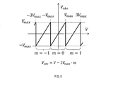
- the orientation of the object is the orientation of the object with respect to the vehicle 80. As shown in FIG. 5, the relative velocities Vobs calculated here have ambiguity based on the wraparound of the velocities.
- the state estimation unit 29 determines whether or not unprocessed target information exists. Specifically, among the registered target candidates, it is determined whether or not there is a target candidate that has not executed the subsequent processes S30 to S60. If it is determined in S20 that there are unprocessed target candidates, the process proceeds to S30.
- the state estimation unit 29 refers to the current state of the target candidate from the past state of the target candidate and the observed value acquired in S10 for one of the unprocessed target candidates. To estimate. Specifically, the state estimation unit 29 calculates the predicted value of the state quantity of the target candidate in the current processing cycle from the estimated value of the state quantity of the target candidate calculated in the previous processing cycle (that is, the past state). To do. Like the observed value, the state quantity of the target may have the distance, the relative velocity, and the direction of the target candidate as elements, and the X-axis coordinate value, the Y-axis coordinate value, the X-direction relative velocity, and the like. And the relative velocity in the Y direction may be included as an element.
- the X-axis is an axis along the width direction of the vehicle 80
- the Y-axis is an axis orthogonal to the X-axis and along the longitudinal direction of the vehicle 80.
- the state quantity of the target may have other elements.
- the state estimation unit 29 determines the observed value to be associated with the calculated predicted value from the observed values acquired in S10. Specifically, the state estimation unit 29 sets a predetermined range centered on the calculated predicted value, and associates the observed value within the predetermined range with the observed value closest to the predicted value with the predicted value. Decide on the target.
- the predetermined range is the range of observations estimated to be obtained from the same object as the predicted value.
- the state estimation unit 29 calculates the estimated value (that is, the current state) in the current processing cycle from the calculated predicted value and the observed value determined as the object to be associated with the Kalman filter or the like. If there is no observed value determined as the object to be associated, for example, the calculated predicted value is used as the estimated value.
- the state estimation unit 29 calculates the likelihood of the calculated estimated value. If the estimated value is calculated from the predicted value and the observed value determined to be associated with the predicted value, the likelihood of the estimated value is increased. At this time, the smaller the difference between the predicted value and the observed value, the higher the likelihood of the estimated value may be. Further, when the observed value determined as the object to be associated does not exist and the estimated value is calculated only from the predicted value, the likelihood of the estimated value is lowered.
- the target selection unit 30 determines whether or not the processing of all target candidates generated from the same object has been completed. That is, it is determined whether or not the estimated value of the state quantity has been calculated for all the target candidates generated from the same object.
- the observed values of the relative velocities Vobs acquired in S10 include ambiguity. Therefore, as shown in FIG. 6, a plurality of target candidates assuming a plurality of folding speeds are generated from the same object. In the present embodiment, three target candidates are generated assuming three turn-back speeds from one object P0.
- the target candidate estimates corresponding to the predicted values associated with the observed values are increased in likelihood.
- the target candidates are deleted and the number of target candidates decreases.
- the target selection unit 30 determines whether or not any of the target candidates generated from the same object satisfies the selection condition.
- the selection condition is a condition for determining that the target candidate is a true target, and for example, the likelihood of the estimated value is equal to or higher than the selection threshold. If none of the target candidates satisfy the selection conditions, the process returns to S20, and if any of the target candidates satisfies the selection conditions, the process proceeds to S60.
- the target selection unit 30 selects a target candidate satisfying the selection condition as a true target and determines the target. If other target candidates generated from the same object remain, the other target candidates are deleted, and in the subsequent processing cycle, only the confirmed target is tracked. In addition, the target selection unit 30 transmits the confirmed target information to the driving support device 50.
- the target candidate generation unit 26 determines whether or not there is an unused observation value among the observation values acquired in S10. That is, it is determined whether or not there is an observed value that is not associated with any of the predicted values among the observed values detected in S10.
- the unused observations correspond to the observations of the object detected for the first time in this processing cycle. If it is determined in S70 that there is no unused observed value, this process ends. On the other hand, if it is determined in S70 that there is an unused observed value, the process proceeds to S80.
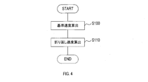
- a target candidate is generated from one of the unused observation values. That is, for the object detected for the first time in this processing cycle, a plurality of target candidates assuming a plurality of folding times are generated. Specifically, the flowchart shown in FIG. 4 is executed.
- the reference speed calculation unit 27 calculates the reference speed for generating a plurality of target candidates. Specifically, as shown in FIG. 8, the reference speed calculation unit 27 uses the observed value of the relative speed Vobs to be equal to or higher than the lower limit of the speed set according to the vehicle speed of the vehicle 80 and the minimum turnaround. The speed is calculated as the reference speed.
- the lower speed lower limit is set to a negative value.
- the relative speed of the stationary object is a value obtained by making the vehicle speed of the vehicle 80 negative. Therefore, as shown in FIGS. 9 to 11, the lower speed lower limit value is set to be equal to or lower than the value obtained by making the vehicle speed of the vehicle 80 negative.
- the lower speed lower limit is set to decrease as the vehicle speed of the vehicle 80 increases. Further, the lower speed lower limit has a portion that is inversely proportional to the vehicle speed of the vehicle 80 in the correspondence relationship between the vehicle speed of the vehicle 80 and the lower speed lower limit value.
- the correspondence is as follows: at a vehicle speed of less than the first speed (for example, 80 km / h), a constant portion in which the lower limit of the speed is set to be constant, and at a vehicle speed of the first speed or more, the vehicle speed. It may have an inversely proportional portion, which is set so that the lower limit of the speed decreases as the amount of the speed increases. Further, as shown in FIG. 10, the correspondence relationship may have an inverse proportional portion set so that the lower limit value of the speed decreases as the vehicle speed increases over the entire range of the vehicle speed. Further, as shown in FIG.
- the correspondence relationship is an inverse proportional portion set so that the lower limit of the speed decreases as the vehicle speed increases at a vehicle speed of less than the second speed (for example, 100 km / h).
- the second speed for example, 100 km / h.
- it may have a constant portion in which the lower limit value of the speed is set to be constant.
- the reference speed calculation unit 27 may calculate the reference speed by using a correspondence relationship suitable for the traveling condition of the vehicle 80.
- the traveling situation is, for example, a situation of traveling in an urban area, a situation of traveling on an expressway, and the like.
- the turn-back speed calculation unit 28 calculates (n + 1) number of turn-back speeds obtained by folding back the reference speed calculated by the reference speed calculation unit 27 from 0 to n (n is a natural number) in the positive direction. ..
- the turn-back speed calculation unit 28 turns back the reference speed by 0 in the positive direction (that is, the reference speed) and turns back by 1 in the positive direction.
- the speed and the folding speed of turning back twice in the positive direction are calculated.
- the turn-back speed calculation unit 28 generates and registers three target target candidates corresponding to each of the three calculated turn-back speeds.
- the turn-back speed calculation unit 28 excludes the target target candidates corresponding to the turn-back speed equal to or higher than the preset speed upper limit value from the three generated target candidates.
- the speed upper limit is set to a positive value and is set to exclude impossible relative speed targets.
- the correspondence relationship between the vehicle speed of the vehicle 80 and the speed upper limit value may have a fixed portion in which the speed upper limit value is set to be constant over the entire range of the vehicle speed.
- the correspondence relationship is that at a vehicle speed lower than the first speed, an inverse proportional portion set so that the upper limit value of the speed decreases as the vehicle speed increases, and a vehicle speed higher than the first speed.
- the correspondence relationship may have an inverse proportional portion set so that the upper limit value of the speed decreases as the vehicle speed increases over the entire range of the vehicle speed.
- the minimum turning speed that is equal to or higher than the lower limit of the speed set according to the vehicle speed of the vehicle 80 is calculated as the reference speed. Further, (n + 1) number of folding speeds obtained by folding back the reference speed from 0 to n in the positive direction are calculated, and (n + 1) target candidates corresponding to (n + 1) number of folding speeds are generated. Thereby, (n + 1) turn-back speeds in an appropriate range according to the vehicle speed of the vehicle 80 can be calculated. Therefore, it is possible to improve the estimation accuracy of the true relative speed while suppressing the processing load. As a result, it is possible to suppress the unrecognized object while suppressing the processing load.
- the lower speed lower value becomes the relative speed of the object approaching the vehicle 80, so that the object approaching the vehicle 80 can be recognized.
- the object that may collide with the vehicle 80 is accurately recognized by having a portion in which the lower speed limit value is inversely proportional to the vehicle speed. be able to.
- the target candidates corresponding to the turn-back speed equal to or higher than the set speed upper limit value are excluded.
- the processing load can be reduced by excluding target candidates having an impossible relative velocity.
- the vehicle 80 has been described as an example of a moving body, but the moving body is not limited to the vehicle 80, and may be a motorcycle, a ship, an airplane, or the like.
- the radar device 10 is not limited to the millimeter wave radar, and may be a laser radar or the like.
- the object tracking device 20 and methods thereof described in the present disclosure are provided by configuring a processor and memory programmed to perform one or more functions embodied by a computer program. It may be realized by a dedicated computer. Alternatively, the object tracking device 20 and its method described in the present disclosure may be realized by a dedicated computer provided by configuring a processor with one or more dedicated hardware logic circuits. Alternatively, the object tracking device 20 and its method described in the present disclosure comprises a processor and memory programmed to perform one or more functions and a processor composed of one or more hardware logic circuits. It may be realized by one or more dedicated computers configured by a combination.
- the computer program may also be stored on a computer-readable non-transitional tangible recording medium as an instruction executed by the computer.
- the method for realizing the functions of each part included in the object tracking device 20 does not necessarily include software, and all the functions may be realized by using one or more hardware.
- a plurality of functions possessed by one component in the above embodiment may be realized by a plurality of components, or one function possessed by one component may be realized by a plurality of components. .. Further, a plurality of functions possessed by the plurality of components may be realized by one component, or one function realized by the plurality of components may be realized by one component. Further, a part of the configuration of the above embodiment may be omitted. In addition, at least a part of the configuration of the above embodiment may be added or replaced with the configuration of the other above embodiment.
Landscapes
- Engineering & Computer Science (AREA)
- Radar, Positioning & Navigation (AREA)
- Remote Sensing (AREA)
- Physics & Mathematics (AREA)
- Computer Networks & Wireless Communication (AREA)
- General Physics & Mathematics (AREA)
- Electromagnetism (AREA)
- Radar Systems Or Details Thereof (AREA)
- Traffic Control Systems (AREA)
Abstract
本開示の1つの局面の物体追跡装置(20)は、取得部(21)と、物体検出部(22)と、距離算出部(23)と、速度算出部(24)と、方位算出部(25)と、候補生成部(26)と、状態推定部(29)と、候補選択部(30)と、を備え、る。候補生成部(26)は、基準速度算出部(27)と、折り返し速度算出部(28)と、を備える。基準速度算出部(27)は、移動体の移動速度に応じて設定された速度下限値以上で且つ最小の折り返し速度を、基準速度として算出する。折り返し速度算出部(28)は、算出された基準速度を、正の方向に0~n(nは自然数)回折り返した複数の折り返し速度を算出する。
Description
本国際出願は、2019年10月15日に日本国特許庁に出願された日本国特許出願第2019-188668号に基づく優先権を主張するものであり、日本国特許出願第2019-188668号の全内容を本国際出願に参照により援用する。
本開示は、物体を追跡する物体追跡装置に関する。
レーダ装置による観測に基づいて物体を追跡する場合に、観測される物体の相対速度が曖昧さを持つことがある。例えば、同一物体について連続的に検出される周波数成分の位相回転から相対速度を求める方式を用いる場合、検出された位相φに対して、実際の位相がφ+2π×m(mは整数)である可能性があり、相対速度を特定することができない。
下記非特許文献1は、複数の相対速度を仮定して複数の物標を生成し、生成した複数の物標を追跡することによって、真の相対速度を特定する技術を提案している。具体的には、複数の仮定のそれぞれに対して尤度を算出し、追跡によって尤度が他よりも高くなった仮定を真の相対速度として特定する。
K. LI. et al, ‘Multitarget Tracking with Doppler Ambiguity’, IEEE TRANSACTIONS ON AEROSPACE AND ELECTRONIC SYSTEMS VOL. 49, NO. 4 OCTOBER 2013
上述した真の相対速度を特定する技術では、相対速度の仮定数の増加に応じて、真の相対速度の推定精度が高くなるが、仮定数の増加に応じて処理負荷が増大し得る。しかしながら、発明者の詳細な検討の結果、仮定数を減らすと、仮定数の相対速度が真の相対速度を含まないことが生じ得るという課題が見出された。ひいては、仮定数を減らすと、物体の追跡ができないことが生じ得り、物体の未認識が生じ得るという課題が見出された。
本開示の1つの局面は、処理負荷を抑制しつつ、物体の未認識を抑制できることが望ましい。
本開示の1つの局面は、物体追跡装置であって、取得部と、物体検出部と、距離算出部と、速度算出部と、方位算出部と、候補生成部と、状態推定部と、候補選択部と、を含む。取得部は、移動体に搭載されたセンサから検出情報を取得するように構成される。物体検出部は、取得部により取得された検出情報から移動体の周辺に存在する物体を検出するように構成される。距離算出部は、物体検出部により検出された物体の距離を算出するように構成される。速度算出部は、物体検出部により検出された物体の相対速度を算出するように構成される。方位算出部は、物体検出部により検出された物体の方位を算出するように構成される。候補生成部は、物体検出部により初めて検出された物体に対して、速度算出部により算出された相対速度から折り返しを仮定した複数の折り返し速度を算出するように構成され、複数の折り返し速度に対応する複数の物標候補を生成するように構成される。状態推定部は、候補生成部により生成された複数の物標候補に含まれる物標候補ごとに、物標候補の過去の状態と、観測情報とから、物標候補の現在の状態を推定するように構成される。観測情報は、距離算出部により算出された距離と、速度算出部により算出された相対速度と、方位算出部により算出された方位と、を含む。候補選択部は、候補生成部により同一の物体に対して生成された複数の物標候補から真の物標であると推定される物標候補を選択するように構成される。候補生成部は、基準速度算出部と、折り返し速度算出部と、を備える。基準速度算出部は、速度算出部により算出された相対速度の折り返し速度であって、速度下限値以上で且つ最小の折り返し速度を、基準速度として算出するように構成される。速度下限値は、移動体の移動速度に応じて設定される。折り返し速度算出部は、基準速度算出部により算出された基準速度を、正の方向に0~n(nは自然数)回折り返した複数の折り返し速度を算出するように構成される。
センサにより観測される物体の相対速度は、物体の速度と移動体の速度とに応じて変化する。移動体にとって注意が必要な物体は移動体の進行方向に存在する物体である。移動体の進行方向に存在する物体の相対速度は、移動体の速度が高いほど、負の側に大きくなる可能性が高い。すなわち、移動体の速度に応じて、仮定すべき相対速度は変化する。また、移動体と衝突する危険性が高い物体を優先して認識する必要がある。そのため、速度の折返し回数を仮定する際には、観測される可能性がある相対速度のうち最も負の側に大きい相対速度を含む必要がある。
よって、本開示の1つの局面の物体追跡装置によれば、移動体の速度に応じて設定された速度下限値以上で且つ最小の折り返し速度が基準速度として算出される。さらに、基準速度を正の方向に折り返した複数の折り返し速度が算出され、複数の折り返し速度に対応する複数の物標候補が生成される。これにより、移動体の速度に応じた適切な範囲における複数の折り返し速度を算出することができる。したがって、処理負荷を抑制しつつ、真の相対速度の推定精度を向上させることができる。ひいては、処理負荷を抑制しつつ、物体の未認識を抑制することができる。
以下、図面を参照しながら、本開示を実施するための形態を説明する。
<1.構成>
まず、本実施形態に係る運転支援システム100の構成について、図1を参照して説明する。運転支援システム100は、レーダ装置10と、物体追跡装置20と、運転支援装置50と、を備える。
まず、本実施形態に係る運転支援システム100の構成について、図1を参照して説明する。運転支援システム100は、レーダ装置10と、物体追跡装置20と、運転支援装置50と、を備える。
レーダ装置10は、車両80の前方中央(例えば、前方バンパの中央)に搭載され、車両80の前方中央の領域を検知エリアとして有してもよい。また、レーダ装置10は、車両80の左前側方及び右前側方(例えば、前方バンパの左端及び右端)のそれぞれに搭載され、車両80の左前方及び右前方の領域のそれぞれを検知エリアとして有してもよい。また、レーダ装置10は、車両80の左後側方及び右後側方(例えば、後方バンパの左端及び右端)のそれぞれに搭載され、車両80の左後方及び右後方の領域のそれぞれを検知エリアとして有してもよい。これらの5台のレーダ装置10は、そのすべてが車両80に搭載されている必要はない。5台のレーダ装置10のうちの1台だけ車両80に搭載されていてもよいし、5台のレーダ装置10のうちの2台以上が車両80に搭載されていてもよい。なお、レーダ装置10は、本開示におけるセンサに相当し、車両80は、本開示における移動体に相当する。
レーダ装置10は、ミリ波レーダであり、複数のアンテナ素子を含む送信アレーアンテナと、複数のアンテナ素子を含む受信アレーアンテナと、を備える。レーダ装置10は、所定の周期で繰り返し送信波を送信し、送信波が物体で反射されて生じた反射波を受信する。さらに、レーダ装置10は、送信波と反射波とを混合してビート信号を生成し、サンプリングしたビート信号(すなわち、検出情報)を物体追跡装置20へ出力する。レーダ装置10は、観測速度に曖昧さが生じる変調方式のレーダ、例えば、Fast Chirp Modulation(FCM)方式のレーダである。
物体追跡装置20は、CPUと、ROM、RAM等の半導体メモリと、を有するマイクロコンピュータを備える。物体追跡装置20は、CPUが、ROMに記憶されている各種プログラムを実行することにより、各種の機能を実現する。具体的には、図2に示すように、物体追跡装置20は、取得部21、物体検出部22、距離算出部23、速度算出部24、方位算出部25、候補生成部26、状態推定部29、及び物標選択部30の機能を備える。候補生成部26は、基準速度算出部27と折り返し速度算出部28の機能を含む。物体追跡装置20は、物体追跡処理を実行し、物体追跡処理の実行により生成した物標情報を運転支援装置50へ出力する。なお、物体追跡処理の詳細は、後述する。
運転支援装置50は、物体追跡装置20により生成された物標情報、及び車両80に搭載された各種センサから取得される車両80の状態情報及び挙動情報を用いて、車両80を制御して、運転支援を実現する。
<2.処理>
次に、第1実施形態に係る物体追跡装置20が実行する物体追跡処理について、図3のフローチャートを参照して説明する。物体追跡装置20は、所定の周期で本処理を繰り返し実行する。
次に、第1実施形態に係る物体追跡装置20が実行する物体追跡処理について、図3のフローチャートを参照して説明する。物体追跡装置20は、所定の周期で本処理を繰り返し実行する。
まず、S10では、取得部21が取得した検出情報から、物体検出部22が車両80の周辺に存在する少なくとも一つの物体を検出する。さらに、検出された物体ごとに、距離算出部23が、検出された物体の距離を算出し、速度算出部24が、検出された物体の相対速度Vobsを算出する。また、検出された物体ごとに、方位算出部25が、検出された物体の方位を算出する。物体の距離は、車両80から物体までの距離であり、物体の相対速度Vobsは、車両80に対する物体の速度である。また、物体の方位は、車両80に対する物体の方位である。なお、図5に示すように、ここで算出される相対速度Vobsは、速度の折り返しに基づいた曖昧さを持っている。
続いて、20では、状態推定部29が、未処理の物標情報が存在するか否か判定する。詳しくは、登録されている物標候補の中で、これ以降に続くS30~S60の処理を実行していない物標候補が存在するか否か判定する。S20において、未処理の物標候補が存在すると判定した場合は、S30の処理へ進む。
S30では、状態推定部29が、未処理の物標候補のうちの1つの物標候補について、物標候補の過去の状態と、S10において取得した観測値とから、物標候補の現在の状態を推定する。詳しくは、状態推定部29が前回の処理サイクルにおいて算出された物標候補の状態量の推定値(すなわち、過去の状態)から、今回の処理サイクルにおける物標候補の状態量の予測値を算出する。物標の状態量は、観測値と同様に、物標候補の距離、相対速度、及び方位を要素として有していてもよいし、X軸座標値、Y軸座標値、X方向相対速度、及びY方向相対速度を要素として有していてもよい。X軸は、車両80の幅方向に沿った軸であり、Y軸は、X軸と直交し、車両80の長手方向に沿った軸である。また、物標の状態量は、その他の要素を有していてもよい。
さらに、状態推定部29は、S10において取得した観測値の中から、算出した予測値と関連づける観測値を決定する。具体的には、状態推定部29は、算出した予測値を中心とした所定の範囲を設定し、所定の範囲内の観測値であって、予測値と最も近い観測値を、予測値と関連付ける対象に決定する。所定の範囲は、予測値と同じ物体から取得されると推定される観測値の範囲である。
そして、状態推定部29は、算出した予測値と、関連付ける対象として決定した観測値とから、カルマンフィルタ等を用いて、今回の処理サイクルにおける推定値(すなわち、現在の状態)を算出する。関連付ける対象として決定された観測値が無い場合には、例えば、算出した予測値を推定値とする。
また、状態推定部29は、算出した推定値の尤度を算出する。予測値とその予測値に関連付ける対象として決定された観測値とから推定値が算出されている場合には、推定値の尤度を上げる。このとき、予測値と観測値の差分が小さいほど、推定値の尤度を高くしてもよい。また、関連付ける対象として決定された観測値が存在せず、予測値のみから推定値が算出されている場合には、推定値の尤度を下げる。
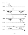
続いて、S40では、物標選択部30が、同一物体から生成されたすべての物標候補の処理が終了したか否か判定する。すなわち、同一の物体から生成されたすべての物標候補について、状態量の推定値が算出されたか否か判定する。図5に示すように、S10において取得された相対速度Vobsの観測値は、曖昧さを含む。そのため、図6に示すように、同一の物体からは、複数の折り返し速度を仮定した複数の物標候補が生成されている。本実施形態では、1個の物体P0から3個の折り返し速度を仮定した3個の物標候補が生成されている。
図6及び7に示すように、処理サイクル1において、物体P0の観測値が初めて検出された場合には、処理サイクル2以降において、物体P0に対して3個の物標候補が生成され、3個の物標候補のそれぞれが追跡される。追跡中に、観測値と関連付けられた予測値に対応する物標候補の推定値は、尤度が上げられる。図6に示す例では、n=0回の折り返し回数に対応する物標候補の推定値の尤度が上げられる。また、追跡中に、推定値の尤度が消去閾値以下になった場合には、物標候補が消去され、物標候補数が減少する。
続いて、S40において、同一物体から生成されたすべての物標候補の処理が終了していないと判定した場合は、S20の処理へ戻り、すべての物標候補の処理が終了したと判定した場合は、S50の処理へ進む。
S50では、物標選択部30が、同一物体から生成された物標候補のいずれかが、選択条件を満たすか否か判定する。選択条件は、物標候補が真の物標であると確定するための条件であり、例えば、推定値の尤度が選択閾値以上であることである。いずれの物標候補も選択条件を満たしていない場合には、S20の処理へ戻り、いずれかの物標候補が選択条件を満たしている場合は、S60の処理へ進む。
S60では、図7に示すように、物標選択部30が、選択条件を満たしている物標候補を真の物標として選択して、物標を確定する。同一の物体から生成された他の物標候補が残っている場合には、他の物標候補を消去し、以後の処理サイクルでは、確定した物標のみを追跡する。また、物標選択部30は、確定した物標の情報を、運転支援装置50へ送信する。
また、S20において、未処理の物標候補が存在しないと判定した場合は、S70の処理へ進む。
S70では、物標候補生成部26が、S10において取得された観測値の中で、未使用の観測値が存在するか否か判定する。すなわち、S10において検出された観測値の中で、いずれかの予測値と関連付けられていない観測値が存在するか否か判定する。未使用の観測値は、今回の処理サイクルにおいて初めて検出された物体の観測値に相当する。S70において、未使用の観測値が存在しないと判定した場合は、本処理を終了する。一方、S70において、未使用の観測値が存在すると判定した場合は、S80の処理へ進む。
続いて、S80では、未使用の観測値のうちの1つの観測値から物標候補を生成する。すなわち、今回の処理サイクルにおいて初めて検出された物体に対して、複数の折り返し回数を仮定した複数の物標候補を生成する。具体的には、図4に示すフローチャートを実行する。
まず、S100では、基準速度算出部27が、複数の物標候補を生成するための基準速度を算出する。具体的には、図8に示すように、基準速度算出部27は、相対速度Vobsの観測値を用いて、車両80の車速に応じて設定された速度下限値以上で、且つ、最小の折り返し速度を、基準速度として算出する。
ここで、少なくとも、車両80に接近する物体を認識できることが望ましい。よって、図9~11に示すように、速度下限値は負の値に設定されている。
さらに、静止物を認識できることが望ましい。静止物の相対速度は車両80の車速を負にした値である。そこで、図9~11に示すように、速度下限値は、車両80の車速を負にした値以下に設定されている。
また、車両80の周辺に存在する物体のうち、特に、車両80と衝突する可能性のある物体を認識できることが望ましい。そこで、図9~11に示すように、速度下限値は、車両80の車速の増加に応じて減少するように設定されている。さらに、速度下限値は、車両80の車速と速度下限値との対応関係において、車両80の車速と逆比例になる部分を有する。
例えば、図9に示すように、対応関係は、第1速度(例えば、80km/h)未満の車速において、速度下限値が一定に設定された一定部分と、第1速度以上の車速において、車速の増加に応じて速度下限値が減少するように設定された逆比例部分と、を有していてもよい。また、図10に示すように、対応関係は、車速の全範囲に亘って、車速の増加に応じて速度下限値が減少するよう設定された逆比例部分を有していてもよい。また、図11に示すように、対応関係は、第2速度(例えば、100km/h)未満の車速において、車速の増加に応じて速度下限値が減少するように設定された逆比例部分と、第2速度以上の車速において、速度下限値が一定に設定された一定部分と、を有していてもよい。
また、車両80の車速と速度下限値との複数の対応関係が用意されていてもよい。この場合、基準速度算出部27は、車両80の走行状況に応じて適した対応関係を用いて、基準速度を算出してもよい。走行状況は、例えば、市街地を走行している状況、高速道路を走行している状況などである。
次に、S110では、折り返し速度算出部28が、基準速度算出部27により算出された基準速度を、正の方向に0~n(nは自然数)折り返した(n+1)個の折り返し速度を算出する。本実施形態では、図8に示すように、折り返し速度算出部28は、基準速度を、正の方向に0回折り返した折り返し速度(すなわち、基準速度)と、正の方向に1回折り返した折り返し速度と、正の方向に2回折り返した折り返し速度と、を算出する。そして、折り返し速度算出部28は、算出した3個の折り返し速度のそれぞれに対応する3個の物標候補を生成して登録する。
このとき、折り返し速度算出部28は、生成した3個の物標候補から、予め設定された速度上限値以上の折り返し速度に対応する物標候補を除外する。速度上限値は、正の値に設定されており、ありえない相対速度の物標を除外するために設定されている。
例えば、図9に示すように、車両80の車速と速度上限値との対応関係は、車速の全範囲に亘って、速度上限値が一定に設定された一定部分を有していてもよい。また、図10に示すように、対応関係は、第1速度未満の車速において、車速の増加に応じて速度上限値が減少するように設定された逆比例部分と、第1速度以上の車速において、速度下限値が一定に設定された一定部分と、を有していてもよい。また、図11に示すように、対応関係は、車速の全範囲に亘って、車速の増加に応じて速度上限値が減少するよう設定された逆比例部分を有していてもよい。S110の処理の後、S70の処理へ戻る。
<3.効果>
以上説明した本実施形態によれば、以下の効果が得られる。
以上説明した本実施形態によれば、以下の効果が得られる。
(1)車両80の車速に応じて設定された速度下限値以上で且つ最小の折り返し速度が基準速度として算出される。さらに、基準速度を正の方向に0~n回折り返した(n+1)個の折り返し速度が算出され、(n+1)個の折り返し速度に対応する(n+1)個の物標候補が生成される。これにより、車両80の車速に応じた適切な範囲における(n+1)個の折り返し速度を算出することができる。したがって、処理負荷を抑制しつつ、真の相対速度の推定精度を向上させることができる。ひいては、処理負荷を抑制しつつ、物体の未認識を抑制することができる。
(2)速度下限値を負の値とすることにより、速度下限値が車両80に接近する物体の相対速度となるため、車両80に接近する物体を認識することができる。
(3)速度下限値を車両80の車速を負にした値以下に設定することにより、静止物を認識することができる。
(4)速度下限値を車両80の車速の増加に応じて減少するように設定することにより、車両80と衝突する可能性のある物体を認識することができる。
(5)車両80の車速と速度下限値との対応関係において、速度下限値が車速と逆比例の関係になる部分を有することにより、車両80と衝突する可能性のある物体を精度良く認識することができる。
(6)生成された複数の物標候補から、設定された速度上限値以上の折り返し速度に対応する物標候補が除外される。ありえない相対速度の物標候補を除外することにより、処理負荷を低減することができる。
(7)速度上限値を正の値に設定することにより、速度下限値と速度上限値との間に、相対速度Vobs=0が含まれるため、車両80と同じ方向に同じ速度で移動する物体(具体的には、先行車両)を認識することができる。
(他の実施形態)
以上、本開示を実施するための形態について説明したが、本開示は上述の実施形態に限定されることなく、種々変形して実施することができる。
以上、本開示を実施するための形態について説明したが、本開示は上述の実施形態に限定されることなく、種々変形して実施することができる。
(a)上記実施形態では、車両80を移動体の一例として説明したが、移動体は車両80に限らず、自動二輪車、船舶、飛行機などでもよい。また、レーダ装置10は、ミリ波レーダに限らず、レーザレーダなどでもよい。
(b)本開示に記載の物体追跡装置20及びその手法は、コンピュータプログラムにより具体化された一つ乃至は複数の機能を実行するようにプログラムされたプロセッサ及びメモリを構成することによって提供された専用コンピュータにより、実現されてもよい。あるいは、本開示に記載の物体追跡装置20及びその手法は、一つ以上の専用ハードウェア論理回路によってプロセッサを構成することによって提供された専用コンピュータにより、実現されてもよい。もしくは、本開示に記載の物体追跡装置20及びその手法は、一つ乃至は複数の機能を実行するようにプログラムされたプロセッサ及びメモリと一つ以上のハードウェア論理回路によって構成されたプロセッサとの組み合わせにより構成された一つ以上の専用コンピュータにより、実現されてもよい。また、コンピュータプログラムは、コンピュータにより実行されるインストラクションとして、コンピュータ読み取り可能な非遷移有形記録媒体に記憶されてもよい。物体追跡装置20に含まれる各部の機能を実現する手法には、必ずしもソフトウェアが含まれている必要はなく、その全部の機能が、一つあるいは複数のハードウェアを用いて実現されてもよい。
(c)上記実施形態における1つの構成要素が有する複数の機能を、複数の構成要素によって実現したり、1つの構成要素が有する1つの機能を、複数の構成要素によって実現したりしてもよい。また、複数の構成要素が有する複数の機能を、1つの構成要素によって実現したり、複数の構成要素によって実現される1つの機能を、1つの構成要素によって実現したりしてもよい。また、上記実施形態の構成の一部を省略してもよい。また、上記実施形態の構成の少なくとも一部を、他の上記実施形態の構成に対して付加又は置換してもよい。
(d)上述した物体追跡装置の他、当該物体追跡装置を構成要素とするシステム、当該物体追跡装置としてコンピュータを機能させるためのプログラム、このプログラムを記録した半導体メモリ等の非遷移的実態的記録媒体、物体追跡方法など、種々の形態で本開示を実現することもできる。
Claims (7)
- 移動体(80)に搭載されたセンサ(10)から検出情報を取得するように構成された取得部(21)と、
前記取得部により取得された検出情報から前記移動体の周辺に存在する物体を検出するように構成された物体検出部(22)と、
前記物体検出部により検出された前記物体の距離を算出するように構成された距離算出部(23)と、
前記物体検出部により検出された前記物体の相対速度を算出するように構成された速度算出部(24)と、
前記物体検出部により検出された前記物体の方位を算出するように構成された方位算出部(25)と、
前記物体検出部により初めて検出された前記物体に対して、前記速度算出部により算出された前記相対速度から折り返しを仮定した複数の折り返し速度を算出するように構成された候補生成部であって、前記複数の折り返し速度に対応する複数の物標候補を生成するように構成された候補生成部(26)と、
前記候補生成部により生成された前記複数の物標候補に含まれる物標候補ごとに、前記物標候補の過去の状態と、観測情報とから、前記物標候補の現在の状態を推定するように構成された状態推定部であって、前記観測情報は、前記距離算出部により算出された前記距離と、前記速度算出部により算出された前記相対速度と、前記方位算出部により算出された前記方位と、を含む、状態推定部(29)と、
前記候補生成部により同一の物体に対して生成された前記複数の物標候補から真の物標と推定される物標候補を選択するように構成された候補選択部(30)と、を備え、
前記候補生成部は、
前記速度算出部により算出された前記相対速度の折り返し速度であって、速度下限値以上で且つ最小の折り返し速度を、基準速度として算出するように構成された基準速度算出部(27)であって、前記速度下限値は、前記移動体の移動速度に応じて設定される、基準速度算出部と、
前記基準速度算出部により算出された前記基準速度を、正の方向に0~n(nは自然数)回折り返した前記複数の折り返し速度を算出するように構成された折り返し速度算出部(28)と、を備える、
物体追跡装置。 - 前記速度下限値は負の値に設定されている、
請求項1に記載の物体追跡装置。 - 前記速度下限値は、前記移動速度を負にした値以下に設定されている、
請求項1又は2に記載の物体追跡装置。 - 前記速度下限値は、前記移動速度の増加に応じて減少するように設定されている、
請求項1~3のいずれか1項に記載の物体追跡装置。 - 前記速度下限値は、前記移動速度と前記速度下限値との対応関係において、前記移動速度と逆比例の関係となる部分を有する、
請求項1~4のいずれか1項に記載の物体追跡装置。 - 前記候補生成部は、生成した前記複数の物標候補から、設定された速度上限値以上の前記折り返し速度に対応する物標候補を除外するように構成されている、
請求項1~5のいずれか1項に記載の物体追跡装置。 - 前記速度上限値は正の値に設定されている、
請求項6に記載の物体追跡装置。
Priority Applications (3)
| Application Number | Priority Date | Filing Date | Title |
|---|---|---|---|
| CN202080072483.XA CN114556141B (zh) | 2019-10-15 | 2020-10-07 | 物体跟踪装置 |
| DE112020004983.3T DE112020004983T5 (de) | 2019-10-15 | 2020-10-07 | Objektverfolgungseinrichtung |
| US17/659,154 US12123939B2 (en) | 2019-10-15 | 2022-04-13 | Object tracking apparatus |
Applications Claiming Priority (2)
| Application Number | Priority Date | Filing Date | Title |
|---|---|---|---|
| JP2019-188668 | 2019-10-15 | ||
| JP2019188668A JP7351706B2 (ja) | 2019-10-15 | 2019-10-15 | 物体追跡装置 |
Related Child Applications (1)
| Application Number | Title | Priority Date | Filing Date |
|---|---|---|---|
| US17/659,154 Continuation US12123939B2 (en) | 2019-10-15 | 2022-04-13 | Object tracking apparatus |
Publications (1)
| Publication Number | Publication Date |
|---|---|
| WO2021075331A1 true WO2021075331A1 (ja) | 2021-04-22 |
Family
ID=75487887
Family Applications (1)
| Application Number | Title | Priority Date | Filing Date |
|---|---|---|---|
| PCT/JP2020/038021 Ceased WO2021075331A1 (ja) | 2019-10-15 | 2020-10-07 | 物体追跡装置 |
Country Status (5)
| Country | Link |
|---|---|
| US (1) | US12123939B2 (ja) |
| JP (1) | JP7351706B2 (ja) |
| CN (1) | CN114556141B (ja) |
| DE (1) | DE112020004983T5 (ja) |
| WO (1) | WO2021075331A1 (ja) |
Cited By (1)
| Publication number | Priority date | Publication date | Assignee | Title |
|---|---|---|---|---|
| WO2022239637A1 (ja) * | 2021-05-14 | 2022-11-17 | 株式会社デンソー | 追跡装置、追跡方法、追跡プログラム |
Families Citing this family (1)
| Publication number | Priority date | Publication date | Assignee | Title |
|---|---|---|---|---|
| EP3904907A1 (en) * | 2020-04-29 | 2021-11-03 | Aptiv Technologies Limited | Methods and systems for tracking an object |
Citations (4)
| Publication number | Priority date | Publication date | Assignee | Title |
|---|---|---|---|---|
| US5757308A (en) * | 1995-10-14 | 1998-05-26 | Volkswagen Ag | Radar process for the measurement of distances and relative speeds between a vehicle and one or more obstructions |
| JP2000065921A (ja) * | 1998-08-18 | 2000-03-03 | Toyota Motor Corp | Fm−cwレーダ装置 |
| JP2017090143A (ja) * | 2015-11-06 | 2017-05-25 | 富士通テン株式会社 | レーダ装置、レーダ装置用の信号処理装置及び信号処理方法 |
| JP2019052952A (ja) * | 2017-09-15 | 2019-04-04 | 株式会社デンソー | レーダ装置 |
Family Cites Families (26)
| Publication number | Priority date | Publication date | Assignee | Title |
|---|---|---|---|---|
| US3935572A (en) * | 1973-11-23 | 1976-01-27 | Hughes Aircraft Company | System for resolving velocity ambiguity in pulse-doppler radar |
| DE10226508A1 (de) * | 2002-06-14 | 2004-01-08 | Dornier Gmbh | Verfahren zur Detektion sowie Geschwindigkeits- und Positionsschätzung von bewegten Objekten in SAR-Bildern |
| JP2009042181A (ja) * | 2007-08-10 | 2009-02-26 | Denso Corp | 推定装置 |
| GB0810860D0 (en) | 2008-06-13 | 2009-01-07 | Bae Systems Plc | A Process and System for Determining the Position and Velocity of an Object |
| JP4957747B2 (ja) * | 2009-05-18 | 2012-06-20 | トヨタ自動車株式会社 | 車両環境推定装置 |
| JP4977806B2 (ja) * | 2010-08-09 | 2012-07-18 | パナソニック株式会社 | レーダイメージング装置、イメージング方法及びそのプログラム |
| JP2013167580A (ja) * | 2012-02-16 | 2013-08-29 | Furuno Electric Co Ltd | 物標速度測定装置、信号処理装置、レーダー装置、物標速度測定方法及びプログラム |
| JP6095899B2 (ja) * | 2012-04-11 | 2017-03-15 | 古野電気株式会社 | 物標運動推定装置、物標運動推定方法、およびレーダ装置 |
| US10054680B2 (en) * | 2014-07-09 | 2018-08-21 | Bae Systems Information And Electronic Systems Integration Inc. | Radar detection of endo-clutter high-value targets using tracker feedback |
| JP2016065733A (ja) * | 2014-09-24 | 2016-04-28 | 三菱電機株式会社 | 物体検出装置 |
| US10062181B1 (en) * | 2015-07-30 | 2018-08-28 | Teradici Corporation | Method and apparatus for rasterizing and encoding vector graphics |
| US10261179B2 (en) * | 2016-04-07 | 2019-04-16 | Uhnder, Inc. | Software defined automotive radar |
| JP6500838B2 (ja) * | 2016-05-18 | 2019-04-17 | 株式会社デンソー | 速度検出装置 |
| EP3415948B1 (en) * | 2017-06-12 | 2021-11-10 | Aptiv Technologies Limited | A method of determining the de-aliased range rate of a target |
| WO2019101962A1 (en) * | 2017-11-23 | 2019-05-31 | Sanofi | Medicament injection device with rotary encoder |
| KR102463720B1 (ko) * | 2017-12-18 | 2022-11-07 | 현대자동차주식회사 | 차량의 경로 생성 시스템 및 방법 |
| US10048366B1 (en) * | 2018-01-30 | 2018-08-14 | Oculii Corp | Systems and methods for virtual aperature radar tracking |
| JP2019132670A (ja) | 2018-01-31 | 2019-08-08 | 住友電気工業株式会社 | レーダ装置 |
| JP7168493B2 (ja) * | 2018-03-23 | 2022-11-09 | 株式会社Soken | レーダ装置 |
| WO2019182043A1 (ja) * | 2018-03-23 | 2019-09-26 | 株式会社Soken | レーダ装置 |
| US10676085B2 (en) * | 2018-04-11 | 2020-06-09 | Aurora Innovation, Inc. | Training machine learning model based on training instances with: training instance input based on autonomous vehicle sensor data, and training instance output based on additional vehicle sensor data |
| US11550061B2 (en) * | 2018-04-11 | 2023-01-10 | Aurora Operations, Inc. | Control of autonomous vehicle based on environmental object classification determined using phase coherent LIDAR data |
| JP7071199B2 (ja) | 2018-04-23 | 2022-05-18 | ヘクセル コーポレイション | ポリマー粉末およびそれを調製する方法 |
| EP3572839A1 (en) * | 2018-05-23 | 2019-11-27 | Aptiv Technologies Limited | Method of estimating a velocity magnitude of a moving target in a horizontal plane and radar detection system |
| DE112018007561B4 (de) * | 2018-06-08 | 2022-03-17 | Mitsubishi Electric Corporation | Radarvorrichtung und signalprozessor |
| KR102175239B1 (ko) * | 2018-08-16 | 2020-11-06 | (주)스마트레이더시스템 | 인공 지능을 이용하여 레이더 신호로부터 타겟을 추적하는 방법 및 그 장치 |
-
2019
- 2019-10-15 JP JP2019188668A patent/JP7351706B2/ja active Active
-
2020
- 2020-10-07 CN CN202080072483.XA patent/CN114556141B/zh active Active
- 2020-10-07 WO PCT/JP2020/038021 patent/WO2021075331A1/ja not_active Ceased
- 2020-10-07 DE DE112020004983.3T patent/DE112020004983T5/de active Pending
-
2022
- 2022-04-13 US US17/659,154 patent/US12123939B2/en active Active
Patent Citations (4)
| Publication number | Priority date | Publication date | Assignee | Title |
|---|---|---|---|---|
| US5757308A (en) * | 1995-10-14 | 1998-05-26 | Volkswagen Ag | Radar process for the measurement of distances and relative speeds between a vehicle and one or more obstructions |
| JP2000065921A (ja) * | 1998-08-18 | 2000-03-03 | Toyota Motor Corp | Fm−cwレーダ装置 |
| JP2017090143A (ja) * | 2015-11-06 | 2017-05-25 | 富士通テン株式会社 | レーダ装置、レーダ装置用の信号処理装置及び信号処理方法 |
| JP2019052952A (ja) * | 2017-09-15 | 2019-04-04 | 株式会社デンソー | レーダ装置 |
Cited By (2)
| Publication number | Priority date | Publication date | Assignee | Title |
|---|---|---|---|---|
| WO2022239637A1 (ja) * | 2021-05-14 | 2022-11-17 | 株式会社デンソー | 追跡装置、追跡方法、追跡プログラム |
| JP7605015B2 (ja) | 2021-05-14 | 2024-12-24 | 株式会社デンソー | 追跡装置、追跡方法、追跡プログラム |
Also Published As
| Publication number | Publication date |
|---|---|
| JP2021063726A (ja) | 2021-04-22 |
| CN114556141B (zh) | 2025-06-13 |
| JP7351706B2 (ja) | 2023-09-27 |
| CN114556141A (zh) | 2022-05-27 |
| US12123939B2 (en) | 2024-10-22 |
| US20220236398A1 (en) | 2022-07-28 |
| DE112020004983T5 (de) | 2022-07-14 |
Similar Documents
| Publication | Publication Date | Title |
|---|---|---|
| US12038495B2 (en) | Object tracking apparatus | |
| US10627484B2 (en) | Radar apparatus | |
| CN113631950B (zh) | 物体追踪装置 | |
| JP6314028B2 (ja) | レーダ装置、車両制御システム、および、信号処理方法 | |
| WO2017164337A1 (ja) | 搭載角度学習装置 | |
| US20230258773A1 (en) | Radar apparatus | |
| US12123939B2 (en) | Object tracking apparatus | |
| JP2019032285A (ja) | レーダ装置および物標検知方法 | |
| JP2019039686A (ja) | レーダ装置および物標検出方法 | |
| JP2018081007A (ja) | レーダ装置および物標検知方法 | |
| JP7674217B2 (ja) | 情報処理装置、物体追跡装置、追跡方法、プログラム | |
| JP2018091785A (ja) | レーダ装置および物標検知方法 | |
| JP3750860B2 (ja) | 画像レーダ装置 | |
| JP2023035011A (ja) | 車両用レーダ装置 | |
| US20210133465A1 (en) | Intersecting road estimation device | |
| US12105186B2 (en) | Object tracking device | |
| JP2018151327A (ja) | レーダ装置および方位組合せ方法 | |
| JP2023035010A (ja) | 車両用レーダ装置 | |
| US20250355108A1 (en) | Raveling speed estimation device | |
| JP2024118246A (ja) | 物体追跡装置 | |
| JP2023146948A (ja) | 物標検出装置、物標検出システム、物標検出方法、物標検出プログラム | |
| JP2021162448A (ja) | レーダ装置 | |
| JP2018096771A (ja) | レーダ装置および物標検知方法 | |
| JP2018115935A (ja) | レーダ装置および移動物位置検出方法 |
Legal Events
| Date | Code | Title | Description |
|---|---|---|---|
| 121 | Ep: the epo has been informed by wipo that ep was designated in this application |
Ref document number: 20876895 Country of ref document: EP Kind code of ref document: A1 |
|
| 122 | Ep: pct application non-entry in european phase |
Ref document number: 20876895 Country of ref document: EP Kind code of ref document: A1 |
|
| WWG | Wipo information: grant in national office |
Ref document number: 202080072483.X Country of ref document: CN |