WO2021070599A1 - ガラス板梱包体の製造方法及び製造装置 - Google Patents
ガラス板梱包体の製造方法及び製造装置 Download PDFInfo
- Publication number
- WO2021070599A1 WO2021070599A1 PCT/JP2020/035532 JP2020035532W WO2021070599A1 WO 2021070599 A1 WO2021070599 A1 WO 2021070599A1 JP 2020035532 W JP2020035532 W JP 2020035532W WO 2021070599 A1 WO2021070599 A1 WO 2021070599A1
- Authority
- WO
- WIPO (PCT)
- Prior art keywords
- glass plate
- pallet
- measuring
- loading
- unit
- Prior art date
- Legal status (The legal status is an assumption and is not a legal conclusion. Google has not performed a legal analysis and makes no representation as to the accuracy of the status listed.)
- Ceased
Links
Images









Classifications
-
- B—PERFORMING OPERATIONS; TRANSPORTING
- B65—CONVEYING; PACKING; STORING; HANDLING THIN OR FILAMENTARY MATERIAL
- B65D—CONTAINERS FOR STORAGE OR TRANSPORT OF ARTICLES OR MATERIALS, e.g. BAGS, BARRELS, BOTTLES, BOXES, CANS, CARTONS, CRATES, DRUMS, JARS, TANKS, HOPPERS, FORWARDING CONTAINERS; ACCESSORIES, CLOSURES, OR FITTINGS THEREFOR; PACKAGING ELEMENTS; PACKAGES
- B65D85/00—Containers, packaging elements or packages, specially adapted for particular articles or materials
- B65D85/30—Containers, packaging elements or packages, specially adapted for particular articles or materials for articles particularly sensitive to damage by shock or pressure
- B65D85/48—Containers, packaging elements or packages, specially adapted for particular articles or materials for articles particularly sensitive to damage by shock or pressure for glass sheets
-
- B—PERFORMING OPERATIONS; TRANSPORTING
- B25—HAND TOOLS; PORTABLE POWER-DRIVEN TOOLS; MANIPULATORS
- B25J—MANIPULATORS; CHAMBERS PROVIDED WITH MANIPULATION DEVICES
- B25J13/00—Controls for manipulators
- B25J13/08—Controls for manipulators by means of sensing devices, e.g. viewing or touching devices
- B25J13/087—Controls for manipulators by means of sensing devices, e.g. viewing or touching devices for sensing other physical parameters, e.g. electrical or chemical properties
-
- B—PERFORMING OPERATIONS; TRANSPORTING
- B65—CONVEYING; PACKING; STORING; HANDLING THIN OR FILAMENTARY MATERIAL
- B65D—CONTAINERS FOR STORAGE OR TRANSPORT OF ARTICLES OR MATERIALS, e.g. BAGS, BARRELS, BOTTLES, BOXES, CANS, CARTONS, CRATES, DRUMS, JARS, TANKS, HOPPERS, FORWARDING CONTAINERS; ACCESSORIES, CLOSURES, OR FITTINGS THEREFOR; PACKAGING ELEMENTS; PACKAGES
- B65D19/00—Pallets or like platforms, with or without side walls, for supporting loads to be lifted or lowered
- B65D19/38—Details or accessories
- B65D19/44—Elements or devices for locating articles on platforms
-
- H—ELECTRICITY
- H10—SEMICONDUCTOR DEVICES; ELECTRIC SOLID-STATE DEVICES NOT OTHERWISE PROVIDED FOR
- H10P—GENERIC PROCESSES OR APPARATUS FOR THE MANUFACTURE OR TREATMENT OF DEVICES COVERED BY CLASS H10
- H10P72/00—Handling or holding of wafers, substrates or devices during manufacture or treatment thereof
- H10P72/10—Handling or holding of wafers, substrates or devices during manufacture or treatment thereof using carriers specially adapted therefor, e.g. front opening unified pods [FOUP]
-
- H—ELECTRICITY
- H10—SEMICONDUCTOR DEVICES; ELECTRIC SOLID-STATE DEVICES NOT OTHERWISE PROVIDED FOR
- H10P—GENERIC PROCESSES OR APPARATUS FOR THE MANUFACTURE OR TREATMENT OF DEVICES COVERED BY CLASS H10
- H10P72/00—Handling or holding of wafers, substrates or devices during manufacture or treatment thereof
- H10P72/50—Handling or holding of wafers, substrates or devices during manufacture or treatment thereof for positioning, orientation or alignment
Definitions
- the present invention relates to a method and an apparatus for manufacturing a glass plate package in which glass plates are loaded on a pallet.
- a glass plate laminate formed by alternately laminating protective sheets and glass plates is placed on a pallet in a vertical posture (approximately vertical posture) or a horizontal posture (approximately horizontal posture). ) May be loaded to form a glass plate packing body, and the work is automated by the packing device.
- Patent Document 1 describes a glass plate supply device having a supply station, a transfer device for transferring a glass plate to a mounting station, a protective sheet supply device for supplying a protective sheet to the mounting station, a glass plate, and the like.
- a packing device including a loading device for loading a protective sheet and a packing pallet device having a loading station on which the pallets are arranged is disclosed.
- the glass plate supplied to the supply station by the glass plate supply device is transferred to the mounting station by the transfer device, and the glass plate and the glass plate are transferred to the mounting station. Overlay with the protective sheet. After that, the glass plate and the protective sheet are loaded from the loading station onto the pallets of the loading station by the loading device. As a result, a glass plate package in which a plurality of glass plates and a plurality of protective sheets are alternately laminated on the pallet is formed.
- the glass plate package is carried out from the loading station, and a new empty pallet is placed at the loading station.
- the pallet when an empty pallet is placed at the loading station, the pallet may be slightly displaced from the predetermined position. If the position of the pallet is displaced, the glass plate cannot be accurately loaded on the pallet, and the glass plate is loaded on the pallet in a state where the position is displaced. In this case, since the commercial value is significantly reduced, the glass plate is taken out from the pallet and the glass plate is reloaded on the pallet. As a result, the manufacturing efficiency is significantly reduced.
- the present invention has been made in view of the above circumstances, and it is a technical subject to efficiently and accurately load a glass plate on a pallet.
- the present invention is for solving the above-mentioned problems, and in a method of manufacturing a glass plate package by loading a glass plate on a pallet with a loading device, a position measuring step of measuring the position of the pallet with the measuring device. And a correction step of controlling the loading device by a control device so as to correct the loading position of the glass plate with respect to the pallet based on the position information of the pallet measured in the position measuring step. It is characterized by.
- the position measuring step the position of the pallet is measured by the measuring device, so that the position of the pallet can be moved even if the pallet is arranged out of the desired position (reference position). Can be identified accurately.
- the control device controls the loading device so as to correct the loading position of the glass plate with respect to the pallet based on the position information of the pallet measured by the position measuring step, so that the pallet is in the desired position.
- the glass plate can be loaded at the optimum position set for the pallet even if it is arranged out of alignment. As a result, it is possible to omit the work of the worker confirming and correcting the positions of the glass plate and the pallet while the loading device is stopped, as in the conventional case. As described above, according to this method, the glass plate can be efficiently and accurately loaded on the pallet.
- the loading device includes a holding portion for holding the glass plate, and the measuring device may be attached to the holding portion. By integrating the measuring device with the holding part of the loading device, the equipment can be simplified.
- the holding portion includes a rectangular main body portion, the main body portion includes a first side and a second side forming a predetermined angle with respect to the first side, and the measuring device includes the first side.
- a first measuring unit and a second measuring unit arranged corresponding to the sides and a third measuring unit arranged corresponding to the second side may be provided. This makes it possible to accurately measure position information such as the position of the pallet in the horizontal direction and the levelness of the pallet.
- the measuring device may include a fourth measuring unit arranged corresponding to the second side. This makes it possible to efficiently measure the position of the pallet.
- the pallet is configured to support the glass plate in a vertical position
- the pallet has a bottom surface that supports the lower end portion of the glass plate
- the measuring device has a position of the bottom surface. May be provided with a measuring unit for measuring.
- the present invention is for solving the above-mentioned problems.
- a measuring device for measuring the position of the pallet and the glass on the pallet. It includes a loading device for loading plates and a control device for controlling the loading device so as to correct the loading position of the glass plate with respect to the pallet based on the position information of the pallet measured by the measuring device. It is characterized by that.
- the position of the pallet can be accurately specified even when the pallet is arranged out of the desired position (reference position). Further, by controlling the loading device by the control device so as to correct the loading position of the glass plate with respect to the pallet based on the position information of the pallet measured by the measuring device, the pallet is arranged out of the intended position. Even in this case, the glass plate can be loaded at the optimum position set for the pallet. As a result, it is possible to omit the work of the worker confirming and correcting the positions of the glass plate and the pallet while the loading device is stopped, as in the conventional case. As described above, according to this apparatus, the glass plate can be efficiently and accurately loaded on the pallet.
- a glass plate can be efficiently and accurately loaded on a pallet.
- 1 to 12 show a method for manufacturing a glass plate package and a first embodiment of a manufacturing apparatus according to the present invention.
- the manufacturing apparatus forms a glass plate packing body PB by alternately laminating a plurality of glass plates G and protective sheets PS on a pallet P.
- the glass plate G to be packed is formed in a rectangular shape, but the shape of the glass plate G is not limited to the present embodiment.
- the glass plate G has a first main surface Ga and a second main surface Gb that are in a front-to-back relationship, and an end surface Gc that connects the first main surface Ga and the second main surface Gb.
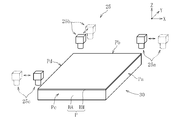
- the pallet P is configured to have a rectangular shape (for example, a rectangular shape) in a plan view.
- the pallet P includes a first side Pa, a second side Pb and a third side Pc forming a right angle to the first side Pa, and a fourth side Pd parallel to the first side Pa.
- the pallet P includes a metal base portion BA and a cushioning member BM provided on the upper surface of the base portion BA.
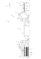
- the manufacturing apparatus 1 loads the transport line 2 for transporting the glass plate G and the glass plate G transported by the transport line 2 on the pallet P to load the glass plate packing body PB.
- a packing line 3 to be formed is provided.
- the transport line 2 includes a conveyor 4 that transports the glass plate G.
- the conveyor 4 includes a supply station 5 capable of taking out the glass plate G.
- the conveyor 4 is composed of a floating conveyor, a roller conveyor, and various other conveyors.
- the floating conveyor has, for example, a floating portion such as an air float that causes the glass plate G to float by ejecting air, and a feeding portion such as a roller that contacts the end portion of the glass plate G and feeds the glass plate G.
- a floating portion such as an air float that causes the glass plate G to float by ejecting air
- a feeding portion such as a roller that contacts the end portion of the glass plate G and feeds the glass plate G.
- the conveyor 4 arranges and conveys a plurality of glass plates G in a row.
- the glass plate G is inspected.
- the inspected glass plate G is loaded on the pallet P at the packing line 3.
- the packing line 3 includes a transfer device 6 for taking out the glass plate G from the transport line 2, a protective sheet supply device 7 for supplying the protective sheet PS, and a loading device 8 for loading the glass plate G and the protective sheet PS on the pallet P. , A control device 9 for executing the control of each of the devices 6 to 8.
- the transfer device 6 includes a base 10, a guide rail 11 that guides the base 10 in a linear reciprocating manner, and a robot arm 12 arranged on the base 10.
- the robot arm 12 has an articulated structure, and a holding portion 13 for holding the glass plate G is provided at the tip thereof.
- the holding portion 13 includes a main body portion 14 and a plurality of suction pads 15 provided on the main body portion 14.
- the main body portion 14 includes a plurality of columnar portions 16 that are formed in parallel at intervals.
- the columnar portion 16 is formed in a hollow shape, and each of the columnar portions 16 is provided with a plurality of suction pads 15.
- the robot arm 12 transfers the glass plate G held by the holding unit 13 from the supply station 5 of the transport line 2 to the supply position of the protective sheet PS in the protective sheet supply device 7. At that time, the robot arm 12 has an operation of reversing the vertical orientation of the first main surface Ga and the second main surface Gb of the glass plate G (reversing operation) and an operation of changing the orientation of the glass plate G (reversing operation). Rotational operation) can be performed.
- the supply station 5 has a structure in which the suction pad 15 and the columnar portion 16 of the transfer device 6 can be inserted below the glass plate G.
- the protective sheet supply device 7 pulls out the strip-shaped sheet from the original roll R and cuts the strip-shaped sheet to a predetermined size to form a single-wafer-shaped protective sheet PS.
- the protective sheet supply device 7 includes a mounting station 17 that serves as a supply position for the protective sheet PS and a mounting position for the glass plate G that is transferred by the transfer device 6, and a cutter that cuts the strip-shaped sheet (for example, a rotary cutter). And guillotine type cutter etc.).
- the protective sheet PS for example, glass interleaving paper is used, but the material and structure of the protective sheet PS are not limited to the aspects of the present embodiment.
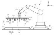
- the loading device 8 includes a base 18, a guide rail 19 that guides the base 18 in a linear reciprocating manner, and a robot arm 20 arranged on the base 18. , Equipped with.
- the robot arm 20 has an articulated structure, and a holding portion 21 for holding both the glass plate G and the protective sheet PS is provided at the tip portion thereof.
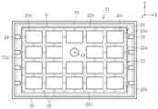
- the holding portion 21 includes a rectangular main body portion 22.
- the main body 22 is formed of a frame formed in a grid pattern.
- the main body 22 has a first side 22a, a second side 22b and a third side 22c forming a predetermined angle (for example, 90 °) with respect to the first side 22a, and a fourth side parallel to the first side 22a.
- the main body 22 includes a plurality of suction pads 23 for holding the glass plate G, a clamp portion 24 for holding the protective sheet PS, and a measuring device 25 for measuring the position of the pallet P.
- Each suction pad 23 is provided on one surface of the main body 22 at predetermined intervals, and is attracted to the surface (for example, the second main surface Gb) of the glass plate G superposed on the protective sheet PS.
- the clamp portion 24 holds the protective sheet PS by gripping the edge portion of the protective sheet PS mounted on the mounting station 17.
- the clamp portion 24 is supported by a support frame 26 fixed to the main body portion 22.
- the measuring device 25 is attached to the main body 22 and is arranged corresponding to the first side 22a of the main body 22.
- a unit 25b and a third measuring unit 25c and a fourth measuring unit 25d arranged corresponding to the second side 22b of the main body 22 are provided.
- the first measurement unit 25a and the second measurement unit 25b are arranged at predetermined intervals along the first side 22a of the main body unit 22.
- the third measurement unit 25c and the fourth measurement unit 25d are arranged at predetermined intervals along the second side 22b of the main body unit 22.
- Each of the measuring units 25a to 25d is composed of a laser sensor, but is not limited to this configuration, and may be configured by a camera or other equipment.
- the control device 9 includes a computer (control panel, PC, etc.) that implements various hardware such as a CPU, ROM, RAM, HDD, monitor, and input / output interface. As shown in FIG. 4, the control device 9 includes an arithmetic processing unit 27 that executes various operations, a storage unit 28 that stores various data, a transfer device 6, a protective sheet supply device 7, a loading device 8, and the like. It is provided with a communication unit 29 that executes communication with. These components 27-29 are connected to each other by a bus.
- the arithmetic processing unit 27 is a transfer operation of the glass plate G by the transfer device 6, a supply operation of the protective sheet PS by the protective sheet supply device 7, a loading operation of the glass plate G by the loading device 8, and a pallet P by the measuring device 25. Executes arithmetic processing related to position measurement control.
- the storage unit 28 stores data and programs necessary for control by the arithmetic processing unit 27.
- the storage unit 28 stores the transfer device 6, the control program related to the protective sheet supply device 7 and the loading device 8, the position data of the pallet P measured by the measuring device 25, the data related to the reference position of the pallet P, and the like.
- the storage unit 28 stores coordinate data of a three-dimensional coordinate system (XYZ Cartesian coordinate system) related to the operation of the robot arm 12 of the transfer device 6 and the robot arm 20 of the loading device 8.
- the reference position of the palette P stored in the storage unit 28 is set in this three-dimensional coordinate system.
- the communication unit 29 is communicably connected to the transfer device 6, the protective sheet supply device 7, and the loading device 8.
- the communication unit 29 transmits the control signal processed by the arithmetic processing unit 27 to each of the devices 6 to 8.
- the communication unit 29 is communicably connected to the robot arm 20 and the measuring device 25 of the loading device 8.
- this method includes a glass plate transport process S1, a transfer step S2, a loading step S3, and a package transport step S4.
- the glass plate G undergoes a predetermined inspection while being conveyed by the conveyor 4 of the transfer line 2.
- the first main surface Ga of the glass plate G is the quality assurance surface (product surface), and in the glass plate transport step S1, the first main surface Ga faces upward. Be transported.
- the position and number of defects on the surface (first main surface Ga) and inside of the glass plate G are detected in the process of being conveyed by the conveyor 4.
- the conveyor 4 arranges the inspected glass plate G at the supply station 5.
- the protective sheet PS is supplied to the mounting station 17 of the protective sheet supply device 7.
- the transfer device 6 holds the glass plate G arranged at the supply station 5 by the holding unit 13 and transfers it to the transfer station 17.
- the holding portion 13 is arranged below the glass plate G arranged in the supply station 5, and the suction pad 15 of the holding portion 13 is used to provide the holding portion 13.
- the lower surface (second main surface Gb) of the glass plate G is adsorbed.
- the glass plate G transported by the conveyor 4 is arranged at the supply station 5 so that its long side is along the transport direction, but when it is transferred to the mounting station 17. , The long side is arranged along the direction orthogonal to the transport direction. Further, the glass plate G mounted on the mounting station 17 is in a state in which the second main surface Gb faces upward and the first main surface Ga faces downward due to the reversing operation of the robot arm 12 in the transfer step S2. It becomes. Therefore, the glass plate G stacked on the protective sheet PS at the mounting station 17 is in a state where the first main surface Ga is in contact with the protective sheet PS.
- a preparatory step of measuring the position of the pallet P and adjusting the position of the glass plate G placed on the pallet P is executed.
- the preparation step includes a position measurement step of measuring the position of the pallet P and a correction step of correcting the loading position of the glass plate G with respect to the pallet P based on the position of the pallet P measured in the position measurement step. Be prepared.
- the control device 9 drives the robot arm 20 of the loading device 8 and moves the main body 22 thereof to the pallet P.
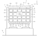
- the main body 22 is arranged at a measurement reference position above the pallet P without holding the glass plate G and the protective sheet PS.
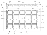
- the measuring portions 25a to 25d of the measuring device 25 are inside the quadrangle partitioned by the first side Pa to the fourth side Pd of the pallet P in a plan view. To position.
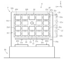
- the control device 9 controls the robot arm 20, moves the main body 22 from the measurement reference position, and starts measuring the position of the pallet P by the measuring device 25.
- the robot arm 20 moves the main body 22 up and down, so that the measurement units 25a to 25d of the measurement device 25 are in the vertical direction (Z-axis direction) with the upper surface of the pallet P (upper surface of the cushioning member BM). ) Is measured (see FIG. 8).
- the robot arm 20 moves the main body 22 in the horizontal direction from the measurement reference position and measures the position of the pallet P in the horizontal direction.
- the first measurement unit 25a and the second measurement unit 25b are each of the pallets P in a plan view. It moves from the inside to the outside of the quadrangle composed of the sides Pa to Pd. At this time, the first measurement unit 25a and the second measurement unit 25b pass above the first side Pa of the pallet P and detect the first side Pa.
- the third measurement unit 25c and the fourth measurement unit 25d move from each side Pa to the pallet P in a plan view. It moves from the inside to the outside of the quadrangle composed of Pd. At this time, the third measuring unit 25c and the fourth measuring unit 25d pass above the second side Pb of the pallet P and detect the second side Pb.
- the robot arm 20 rotates the main body 22 at the measurement reference position around the rotation axis O along the vertical direction (Z-axis direction) by the movement of the wrist joint.
- the second measurement unit 25b and the third measurement unit 25c detect the positions of the first side Pa and the second side Pb of the pallet P related to the rotation operation around the rotation axis O.
- Each measuring unit 25a to 25d transmits the measured position information (measurement data) of the pallet P to the control device 9.
- the control device 9 starts the correction process by the arithmetic processing unit 27.
- the arithmetic processing unit 27 of the control device 9 calculates the inclination angle (horizontal degree) of the upper surface with respect to the horizontal direction from the data related to the distance between the measurement units 25a to 25d in the vertical direction and the upper surface of the pallet P. To do.
- the arithmetic processing unit 27 provides position information (each measuring unit 25a) of the first side Pa and the second side Pb of the pallet P when each measuring unit 25a to 25d moves in the horizontal direction and when it rotates around the rotation axis O.
- the amount of deviation from the reference position of the pallet P is calculated based on the moving distance (to 25d) and the data of the reference position stored in the storage unit 28.
- the arithmetic processing unit 27 shifts the pallet P from the reference position in the horizontal direction due to the difference between the measured value when the main body unit 22 (measuring device 25) is moved in the horizontal direction and the value related to the reference position.
- the amount can be calculated.
- the arithmetic processing unit 27 is said to be based on the difference between the measured value when the main body unit 22 (measuring device 25) is rotated around the rotation axis O and the value related to the reference position stored in the storage unit 28.
- the amount of misalignment (amount of tilt deviation) of the pallet P around the rotation axis O can be calculated.
- the arithmetic processing unit 27 corrects the data of the loading position of the glass plate G with respect to the pallet P based on the calculated misalignment amount of the pallet P.
- the control device 9 transmits a control signal to the robot arm 20 so that the glass plate G is conveyed to the corrected loading position.
- the loading device 8 holds the glass plate G and the protective sheet PS mounted on the mounting station 17 by the holding portion 21 of the robot arm 20, and transfers them to the loading station 30. ..
- the loading device 8 arranges the holding portion 21 above the mounting station 17 by the operation of the robot arm 20, then lowers the holding portion 21 and uses the suction pad 23 to lower the glass plate G.
- the two main surfaces Gb are adsorbed.
- the loading device 8 causes the clamp portion 24 of the holding portion 21 to grip the edge portion of the protective sheet PS. As a result, the glass plate G and the protective sheet PS that are overlapped on the mounting station 17 are held by the holding portion 21.
- the loading device 8 drives the robot arm 20 to move the holding unit 21 to the loading station 30.
- the robot arm 20 changes the orientation of the glass plate G and the protective sheet PS held by the holding portion 21 by the movement of the wrist joint or the like.
- the loading device 8 arranges the holding portion 21 above the pallet P.
- the robot arm 20 arranges the main body 22 based on the corrected position information received from the control device 9. After that, the robot arm 20 lowers the holding portion 21 to approach the pallet P.
- the loading device 8 releases the suction pad 23 of the holding portion 21 from sucking the glass plate G and the clamp portion 24 from gripping the protective sheet PS.
- the first glass plate G is placed on the upper surface of the cushioning member BM of the pallet P together with the protective sheet PS.
- the glass plate G placed on the pallet P is in a state of being rotated by 90 ° in a plan view as compared with the case where the glass plate G is placed on the mounting station 17.
- the robot arm 20 holds the second glass plate G and the protective sheet PS mounted on the mounting station 17, and the second glass plate G is mounted on the pallet P. It is loaded on the first glass plate G.
- the loading process S3 is completed, and a glass plate packing body PB formed by alternately laminating a plurality of glass plates G and protective sheets PS on the pallet P is formed. ..
- the glass plate packing body PB is carried out to the outside through a packing body transport path (not shown).
- the glass plate package PB is carried out by using a transport means such as a hand lifter, a forklift, or an automatic guided vehicle (AGV).
- a transport means such as a hand lifter, a forklift, or an automatic guided vehicle (AGV).
- AGV automatic guided vehicle
- a new empty pallet P is carried into the loading station 30 where the glass plate packing body PB is carried out (pallet supply process).
- the new empty pallet P supplied to the loading station 30 is measured by the measuring device 25 in the next position measuring step.
- the pallet P is formed by measuring the position of the pallet P by the measuring apparatus 25 in the position measuring step of the loading step S3.
- the position of the pallet P can be accurately specified even when the pallet P is arranged deviated from the reference position.
- the control device 9 corrects the loading position of the glass plate G with respect to the pallet P based on the position information of the pallet P measured by the position measuring step (measuring device 25). Controls the loading device 8. Therefore, even when the pallet P is arranged so as to deviate from the reference position, the glass plate G can be loaded at the optimum position set for the pallet P. As a result, it is possible to omit the work of the worker confirming / correcting the position of the pallet P with the loading device 8 stopped, as in the conventional case. Therefore, according to the present invention, the glass plate G can be efficiently and accurately loaded on the pallet P.
- FIG. 13 shows a second embodiment of a manufacturing method and a manufacturing apparatus for a glass plate package according to the present invention.
- the mode of the measuring device and the loading process is different from that of the first embodiment.
- the measuring device 25 is not provided in the holding portion 21 of the loading device 8. In the present embodiment, the measuring device 25 is deployed at the loading station 30 independently of the loading device 8. Except for the configuration of the measuring device 25, the manufacturing device according to the second embodiment includes a transport line 2 and a packing line 3 as in the first embodiment.
- the measuring device 25 includes a first measuring unit 25a, a second measuring unit 25b, and a third measuring unit 25c.
- Each of the measuring units 25a to 25c is configured to be three-dimensionally movable by a moving mechanism.
- Each of the measuring units 25a to 25c can move to a standby position (position indicated by the alternate long and short dash line) away from the pallet P and a measurable measurement position (position indicated by the solid line) of the pallet P.
- Each of the measuring units 25a to 25c is composed of a camera, but may be composed of a laser sensor or other equipment.
- the measuring units 25a to 25c are communicably connected to the control device 9.
- the first measurement unit 25a takes an image of the first side Pa of the palette P at the measurement position.
- the second measurement unit 25b takes an image of the second side Pb on the palette P at the measurement position.
- the third measurement unit 25c takes an image of the fourth side Pd on the palette P at the measurement position.
- each of the measuring units 25a to 25c receives a control signal from the control device 9 and moves from the standby position to the measuring position.
- Each measuring unit 25a to 25c measures (imaging) the position of the pallet P (the position of the first side Pa, the second side Pb, and the fourth side Pd) at the measurement position.
- the image data captured by the measuring units 25a to 25c is transmitted to the control device 9.
- the measuring units 25a to 25c move from the measuring position to the standby position.
- the arithmetic processing unit 27 of the control device 9 specifies the position of the palette P by image processing on the image data received from each of the measuring units 25a to 25c.
- the arithmetic processing unit 27 compares the measured position information related to the pallet P with the value related to the reference position, and calculates the amount of displacement of the pallet P with respect to the reference position.
- the control device 9 corrects the data of the loading position of the glass plate G by the robot arm 20 of the loading device 8 based on the amount of deviation of the pallet P from the reference position.
- the control device 9 transmits a control signal related to the corrected position data to the robot arm 20.
- the robot arm 20 loads the held glass plate G and the protective sheet PS on the pallet P based on the corrected position data received from the control device 9.
- FIG. 14 to 19 show a third embodiment of a manufacturing method and a manufacturing apparatus for a glass plate package according to the present invention.
- the aspects of the pallet, the measuring device, and the loading process are different from those in the first embodiment.
- the glass plate packaging body according to the present embodiment is manufactured by loading the glass plate G on the pallet P in a vertical position.
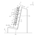
- the pallet P has a side surface SS that supports the surface (first main surface Ga) of the glass plate G in a vertical posture, and bottom surfaces BS1 and BS2 that support the lower end portion of the glass plate G.
- the side surface SS of the pallet P is inclined at a predetermined angle (for example, 1 ° to 60 °) with respect to the vertical direction (Z-axis direction).
- the side surface SS is configured to have a rectangular shape, for example, but is not limited to this shape.
- the side surface SS has a first side SSa, a second side SSb orthogonal to the first side SSa, a third side SSc, and a fourth side SSd substantially parallel to the first side SSa.
- the bottom surfaces BS1 and BS2 of the pallet P are inclined at a predetermined angle with respect to the horizontal direction (Y-axis direction).
- the bottom surface BS1 and BS2 include a first bottom surface BS1 and a second bottom surface BS2 provided at predetermined intervals.
- the angle formed by each of the bottom surface BS1 and BS2 and the side surface SS is set to about 90 °, but the angle is not limited to this mode.
- the measuring device 25 of the loading device 8 includes a first measuring unit 25a to a fourth measuring unit 25d for measuring the position of the side surface SS of the pallet P, and a fifth measuring unit 25e for measuring the positions of the bottom surfaces BS1 and BS2 of the pallet P. , Equipped with.
- the configuration of the first measuring unit 25a to the fourth measuring unit 25d is the same as that of the first embodiment.
- the fifth measuring unit 25e is composed of, for example, a laser sensor, but is not limited to this configuration.
- the fifth measuring unit 25e is composed of two measuring units so as to measure the position of the first bottom surface BS1 and the position of the second bottom surface BS2.
- the fifth measuring unit 25e is fixed to the lower part of the support frame 26 related to the holding unit 21.
- the fifth measuring unit 25e may be fixed to, for example, the third side 22c of the main body unit 22 related to the holding unit 21.
- the control device 9 controls the robot arm 20 and arranges the holding portion 21 that does not hold the glass plate G at the first measurement reference position shown in FIGS. 14 and 15.
- the third measuring unit 25c and the fourth measuring unit 25d of the measuring device 25 are located above the second side SSb of the side surface SS of the pallet P.
- the holding portion 21 at the first measurement reference position is in a state of being inclined at the same angle as the inclination angle of the side surface SS so as to be parallel to the side surface SS.
- the control device 9 controls the robot arm 20, moves the holding unit 21 from the first measurement reference position, and starts measuring the position of the pallet P by the measuring device 25.
- the main body 22 of the holding portion 21 is set below the first measurement reference position (position indicated by the alternate long and short dash line) for the second measurement. Move to the reference position (position indicated by the solid line).
- the holding portion 21 moves downward along a direction substantially parallel to the inclination direction of the side surface SS of the pallet P. In other words, the holding portion 21 moves downward along a direction substantially orthogonal to the bottom surfaces BS1 and BS2 of the pallet P.
- the third measuring unit 25c and the fourth measuring unit 25d of the measuring device 25 detect the second side SSb of the side surface SS of the pallet P. Further, the measuring device 25 executes the measurement of the positions of the bottom surfaces BS1 and BS2 by the fifth measuring unit 25e during this movement.
- the two fifth measuring units 25e measure the change in the distance from the first bottom surface BS1 and the change in the distance from the second bottom surface BS2.
- the heights (positions in the Z-axis direction) of the bottom surfaces BS1 and BS2 of the pallet P can be measured by the two fifth measuring units 25e.
- the inclinations of the bottom surfaces BS1 and BS2 with respect to the X-axis direction can be measured.
- the robot arm 20 moves the holding portion 21 along the horizontal direction (X-axis direction).
- the first measuring unit 25a and the second measuring unit 25b of the measuring device 25 move from the inside to the outside of the quadrangle formed by the sides SSa to SSd related to the side surface SS of the pallet P in the front view.
- the first measurement unit 25a and the second measurement unit 25b detect the first side SSa of the side surface SS.
- the fifth measuring unit 25e detects the positions of the bottom surfaces BS1 and BS2 of the pallet P in the horizontal direction (X-axis direction). After that, the robot arm 20 moves the holding portion 21 to the second measurement reference position.
- the robot arm 20 may rotate the main body 22 at the second measurement reference position around its rotation axis O by the operation of its wrist joint.
- the second measuring unit 25b and the third measuring unit 25c of the measuring device 25 can detect the first side SSa and the second side SSb on the side surface SS of the pallet P.
- the robot arm 20 moves (approaches / separates) the holding portion 21 (main body portion 22) at the second reference position along a direction (Y-axis direction) substantially orthogonal to the side surface SS of the pallet P. You may let me. Due to the movement of the holding unit 21, the first measuring unit 25a to the fourth measuring unit 25d of the measuring device 25 measure the change in the distance from the side surface SS. Further, at the time of this movement, the fifth measuring unit 25e may detect the position of the bottom surface BS1 and BS2 of the pallet P in the substantially orthogonal direction (Y-axis direction), and the bottom surface BS1 with respect to the substantially orthogonal direction (Y-axis direction). , BS2 tilt may be measured.
- Each measuring unit 25a to 25e transmits the position information (measurement data) of the measured pallets P (side surface SS and bottom surface BS1 and BS2) to the control device 9.
- the control device 9 starts the correction process by the arithmetic processing unit 27.
- the arithmetic processing unit 27 calculates the inclination angle of the side surface SS from the data related to the distance between the first measurement unit 25a to the fourth measurement unit 25d and the side surface SS of the pallet P. Further, the arithmetic processing unit 27 determines the reference position of the pallet P based on the measured position information of the first side SSa and the second side SSb of the side surface SS and the reference position data stored in the storage unit 28. Calculate the amount of deviation from.
- the arithmetic processing unit 27 stores data related to the position information (position and inclination in the X-axis direction to the Z-axis direction) of the bottom surfaces BS1 and BS2 of the pallet P detected by the fifth measurement unit 25e and the storage unit 28.
- the amount of deviation of the pallet P from the reference position is calculated based on the data of the reference position.
- the arithmetic processing unit 27 determines the rotation axis based on the difference between the measured value when the main body unit 22 (measuring device 25) is rotated around the rotation axis O and the value related to the reference position stored in the storage unit 28. The amount of misalignment of the side surface SS around O is calculated.
- the arithmetic processing unit 27 corrects the data of the loading position of the glass plate G with respect to the pallet P based on the calculated misalignment amount of the pallet P.
- the control device 9 transmits a control signal to the robot arm 20 so that the glass plate G is conveyed to the corrected loading position.
- the loading device 8 holds the glass plate G and the protective sheet PS mounted on the mounting station 17 by the holding portion 21 of the robot arm 20, and transfers them to the loading station 30.
- the robot arm 20 places the glass plate G and the protective sheet PS held by the holding portion 21 on the pallet P.
- the first main surface Ga of the glass plate G is supported by the side surface SS of the pallet P.
- the lower end portion of the glass plate G is supported by the bottom surfaces BS1 and BS2.
- the loading device 8 loads the second and subsequent glass plates G together with the protective sheet PS on the pallet P.
- the present invention is not limited to the configuration of the above embodiment, and is not limited to the above-mentioned action and effect.
- the present invention can be modified in various ways without departing from the gist of the present invention.
- the loading device 8 includes a measuring device 25 including a first measuring unit 25a to a fourth measuring unit 25d, but the present invention is not limited to this configuration.
- a measuring device 25 including a first measuring unit 25a to a fourth measuring unit 25d, but the present invention is not limited to this configuration.
- one of the first measuring unit 25a to the fourth measuring unit 25d may be omitted to configure the measuring device 25.
- an additional measuring unit 25 is provided in the measuring device 25, and the measuring device 25 having more measuring units (five or more) than the first embodiment and more measuring units (four or more) than the second embodiment is used. You may.
- the arithmetic processing unit 27 of the control device 9 determines the inclination angle (horizontal degree) from the data related to the distance between the measurement units 25a to 25d in the vertical direction and the upper surface of the pallet P.
- the amount of displacement of the pallet P from the reference position in the horizontal direction is calculated from the difference between the measured value when the main body 22 (measuring device 25) is moved in the horizontal direction and the value related to the reference position.
- the pallet P around the rotating shaft O Due to the difference between the measured value when the main body 22 (measuring device 25) is rotated around the rotating shaft O and the value related to the reference position stored in the storage unit 28, the pallet P around the rotating shaft O
- the amount of misalignment is calculated, the present invention is not limited to this configuration.
- the calculation and / or correction of the tilt angle (horizontal degree) and the position shift amount (tilt shift amount) of the pallet P around the rotation axis O may be omitted.
- the measurement while rotating the main body 22 (measuring device 25) around the rotating shaft O is omitted, and the measured value when the main body 22 (measuring device 25) is moved in the horizontal direction is taken from the measured value around the rotating shaft O.
- the position shift amount (tilt shift amount) of the pallet P may be calculated.
- the inclination angle (horizontal degree) is set in the vertical direction (Z-axis direction) with the upper surface of the pallet P (upper surface of the cushioning member BM) on each of the measuring units 25a to 25d of the measuring device 25 without moving the main body 22 up and down.
- the distance may be measured and calculated from the result.
- the loading device 8 loads the glass plate G and the protective sheet PS on the pallet P at the same time, but the present invention is not limited to this configuration.
- the loading device 8 may load the glass plate G and the protective sheet PS on the pallet P in this order.
- the loading device 8 may include a first loading device for loading the glass plate G and a second loading device for loading the protective sheet PS.
- the amount of deviation between the side surface SS and the bottom surface BS1 and BS2 of the pallet P was calculated, but only one of them may be calculated.
- the amount of deviation of the bottom surfaces BS1 and BS2 may be appropriately selected and measured from the positions in the X-axis direction to the Z-axis direction and the inclinations with respect to the X-axis direction and the Y-axis direction. May be omitted. For example, if the misalignment of the glass plate in the Y-axis direction is allowed to some extent, the measurement of the position in the Y-axis direction and the inclination with respect to the Y-axis direction may be omitted.
Landscapes
- Engineering & Computer Science (AREA)
- Mechanical Engineering (AREA)
- Human Computer Interaction (AREA)
- Robotics (AREA)
- Manipulator (AREA)
- Packaging Frangible Articles (AREA)
- Container, Conveyance, Adherence, Positioning, Of Wafer (AREA)
- Specific Conveyance Elements (AREA)
Abstract
Description
8 積載装置
9 制御装置
21 保持部
22 本体部
22a 本体部の第一辺
22b 本体部の第二辺
25 測定装置
25a 第一測定部
25b 第二測定部
25c 第三測定部
25d 第四測定部
25e 第五測定部
BS1 第一底面
BS2 第二底面
G ガラス板
P パレット
PB ガラス板梱包体
Claims (6)
- 積載装置によってガラス板をパレットに積載することでガラス板梱包体を製造する方法において、
前記パレットの位置を測定装置によって測定する位置測定工程と、
前記位置測定工程において測定された前記パレットの位置情報に基づいて、前記パレットに対する前記ガラス板の積載位置を補正するように、制御装置によって前記積載装置を制御する補正工程と、を備えることを特徴とするガラス板梱包体の製造方法。 - 前記積載装置は、前記ガラス板を保持する保持部を備え、
前記測定装置は、前記保持部に取り付けられる請求項1に記載のガラス板梱包体の製造方法。 - 前記保持部は、矩形状の本体部を備え、
前記本体部は、第一辺と、前記第一辺に対して所定の角度を為す第二辺とを含み、
前記測定装置は、前記第一辺に対応して配置される、第一測定部及び第二測定部と、前記第二辺に対応して配置される第三測定部と、を備える請求項2に記載のガラス板梱包体の製造方法。 - 前記測定装置は、前記第二辺に対応して配置される第四測定部を備える請求項3に記載のガラス板梱包体の製造方法。
- 前記パレットは、前記ガラス板を縦姿勢で支持するように構成されており、
前記パレットは、前記ガラス板の下端部を支持する底面を備え、
前記測定装置は、前記底面の位置を測定する測定部を備える請求項1から4のいずれか一項に記載のガラス板梱包体の製造方法。 - ガラス板をパレットに積載することでガラス板梱包体を製造する装置において、
前記パレットの位置を測定する測定装置と、
前記パレットに前記ガラス板を積載する積載装置と、
前記測定装置によって測定された前記パレットの位置情報に基づいて、前記パレットに対する前記ガラス板の積載位置を補正するように、前記積載装置を制御する制御装置と、を備えることを特徴とするガラス板梱包体の製造装置。
Priority Applications (3)
| Application Number | Priority Date | Filing Date | Title |
|---|---|---|---|
| CN202080060140.1A CN114286788B (zh) | 2019-10-11 | 2020-09-18 | 玻璃板捆包体的制造方法以及制造装置 |
| KR1020227005494A KR102858488B1 (ko) | 2019-10-11 | 2020-09-18 | 유리판 곤포체의 제조 방법 및 제조 장치 |
| JP2021550628A JP7590698B2 (ja) | 2019-10-11 | 2020-09-18 | ガラス板梱包体の製造方法及び製造装置 |
Applications Claiming Priority (2)
| Application Number | Priority Date | Filing Date | Title |
|---|---|---|---|
| JP2019-187731 | 2019-10-11 | ||
| JP2019187731 | 2019-10-11 |
Publications (1)
| Publication Number | Publication Date |
|---|---|
| WO2021070599A1 true WO2021070599A1 (ja) | 2021-04-15 |
Family
ID=75437893
Family Applications (1)
| Application Number | Title | Priority Date | Filing Date |
|---|---|---|---|
| PCT/JP2020/035532 Ceased WO2021070599A1 (ja) | 2019-10-11 | 2020-09-18 | ガラス板梱包体の製造方法及び製造装置 |
Country Status (5)
| Country | Link |
|---|---|
| JP (1) | JP7590698B2 (ja) |
| KR (1) | KR102858488B1 (ja) |
| CN (1) | CN114286788B (ja) |
| TW (1) | TWI846958B (ja) |
| WO (1) | WO2021070599A1 (ja) |
Families Citing this family (1)
| Publication number | Priority date | Publication date | Assignee | Title |
|---|---|---|---|---|
| CN116573248A (zh) * | 2023-06-20 | 2023-08-11 | 彩虹(合肥)液晶玻璃有限公司 | 一种玻璃基板精准定位包装方法 |
Citations (2)
| Publication number | Priority date | Publication date | Assignee | Title |
|---|---|---|---|---|
| JP2007000940A (ja) * | 2005-06-21 | 2007-01-11 | Central Glass Co Ltd | ガラス板のパレットへの積載方法および装置 |
| JP2010030744A (ja) * | 2008-07-29 | 2010-02-12 | Nippon Electric Glass Co Ltd | 板状ワークの移送設備および移送方法 |
Family Cites Families (4)
| Publication number | Priority date | Publication date | Assignee | Title |
|---|---|---|---|---|
| JP3206887B2 (ja) * | 1996-12-20 | 2001-09-10 | セントラル硝子株式会社 | パレットへの積込位置補正方法及び装置 |
| JP2009295682A (ja) * | 2008-06-03 | 2009-12-17 | Mitsubishi Materials Techno Corp | ガラス板のハンドリング装置 |
| JP5196158B2 (ja) | 2008-10-07 | 2013-05-15 | 日本電気硝子株式会社 | ガラス基板梱包装置およびその梱包方法 |
| JP6079044B2 (ja) * | 2012-08-20 | 2017-02-15 | 大日本印刷株式会社 | 枠体搬送装置および枠体搬送装置を用いた枠体搬送方法 |
-
2020
- 2020-09-18 WO PCT/JP2020/035532 patent/WO2021070599A1/ja not_active Ceased
- 2020-09-18 CN CN202080060140.1A patent/CN114286788B/zh active Active
- 2020-09-18 JP JP2021550628A patent/JP7590698B2/ja active Active
- 2020-09-18 KR KR1020227005494A patent/KR102858488B1/ko active Active
- 2020-09-26 TW TW109133540A patent/TWI846958B/zh active
Patent Citations (2)
| Publication number | Priority date | Publication date | Assignee | Title |
|---|---|---|---|---|
| JP2007000940A (ja) * | 2005-06-21 | 2007-01-11 | Central Glass Co Ltd | ガラス板のパレットへの積載方法および装置 |
| JP2010030744A (ja) * | 2008-07-29 | 2010-02-12 | Nippon Electric Glass Co Ltd | 板状ワークの移送設備および移送方法 |
Also Published As
| Publication number | Publication date |
|---|---|
| KR102858488B1 (ko) | 2025-09-11 |
| JP7590698B2 (ja) | 2024-11-27 |
| CN114286788B (zh) | 2025-02-18 |
| TWI846958B (zh) | 2024-07-01 |
| TW202115819A (zh) | 2021-04-16 |
| JPWO2021070599A1 (ja) | 2021-04-15 |
| KR20220079812A (ko) | 2022-06-14 |
| CN114286788A (zh) | 2022-04-05 |
Similar Documents
| Publication | Publication Date | Title |
|---|---|---|
| JP6005299B2 (ja) | ロボットシステムおよびロボットシステムの制御方法 | |
| CN102105375B (zh) | 板状工件的移送设备及移送方法 | |
| KR102373134B1 (ko) | 글라스 기판 적재시스템 및 적재방법 | |
| CN111390893B (zh) | 用于生产变压器芯的方法及定位系统 | |
| JP4641859B2 (ja) | ガラス板収納用箱状容器の位置調整装置 | |
| KR20210075168A (ko) | 물품 이송탑재 설비 | |
| KR101902814B1 (ko) | 부품의 불량을 자동으로 검사하면서 정확한 위치로 이송할 수 있는 부품 자동 검사 및 정위치 로딩 장치 | |
| JP2014043322A (ja) | 自動箱詰め方法および装置 | |
| KR20220097135A (ko) | 반도체 패키지 절단 및 분류 장치 | |
| JP5282137B2 (ja) | 基板作業装置 | |
| JP4543833B2 (ja) | 懸垂式昇降搬送装置における搬送台車の教示装置 | |
| JP7590698B2 (ja) | ガラス板梱包体の製造方法及び製造装置 | |
| JP6330437B2 (ja) | ローダ装置、板材搬送方法、及び板材加工システム | |
| JP5879392B2 (ja) | 積載された長方形の被加工材を折曲げ加工機へ供給するローディング装置 | |
| KR100865823B1 (ko) | 유리판의 이동 탑재 장치, 삽입 방법, 삽입 장치 및 유리판 수납용 상자형 용기의 위치 조정 장치 | |
| TWI730134B (zh) | 機器人、機器人之控制方法、教示用治具及機器人之教示方法 | |
| KR102373129B1 (ko) | 글라스 기판 팔렛트 적재시스템 및 적재방법 | |
| JP2022102888A (ja) | 基板搬送ロボットの制御装置及び関節モータの制御方法 | |
| JP5118896B2 (ja) | 搬送ロボットシステム | |
| JP6472485B2 (ja) | 搬送装置及び搬送方法 | |
| JP5489259B2 (ja) | 供出装置及びその供出方法 | |
| CN102617028A (zh) | 加工管理系统 | |
| JP5923278B2 (ja) | 切断製品の吸着搬送格納方法及び装置 | |
| JP5064181B2 (ja) | 基板切断装置 | |
| TW202106586A (zh) | 物品搬送設備 |
Legal Events
| Date | Code | Title | Description |
|---|---|---|---|
| 121 | Ep: the epo has been informed by wipo that ep was designated in this application |
Ref document number: 20874094 Country of ref document: EP Kind code of ref document: A1 |
|
| ENP | Entry into the national phase |
Ref document number: 2021550628 Country of ref document: JP Kind code of ref document: A |
|
| NENP | Non-entry into the national phase |
Ref country code: DE |
|
| 122 | Ep: pct application non-entry in european phase |
Ref document number: 20874094 Country of ref document: EP Kind code of ref document: A1 |
|
| WWG | Wipo information: grant in national office |
Ref document number: 202080060140.1 Country of ref document: CN |