WO2021070533A1 - 電動車両用バッテリーケースの製造方法および電動車両用バッテリーケース - Google Patents
電動車両用バッテリーケースの製造方法および電動車両用バッテリーケース Download PDFInfo
- Publication number
- WO2021070533A1 WO2021070533A1 PCT/JP2020/033653 JP2020033653W WO2021070533A1 WO 2021070533 A1 WO2021070533 A1 WO 2021070533A1 JP 2020033653 W JP2020033653 W JP 2020033653W WO 2021070533 A1 WO2021070533 A1 WO 2021070533A1
- Authority
- WO
- WIPO (PCT)
- Prior art keywords
- frame
- molded
- battery case
- electric vehicle
- tray
- Prior art date
- Legal status (The legal status is an assumption and is not a legal conclusion. Google has not performed a legal analysis and makes no representation as to the accuracy of the status listed.)
- Ceased
Links
Images












Classifications
-
- H—ELECTRICITY
- H01—ELECTRIC ELEMENTS
- H01M—PROCESSES OR MEANS, e.g. BATTERIES, FOR THE DIRECT CONVERSION OF CHEMICAL ENERGY INTO ELECTRICAL ENERGY
- H01M50/00—Constructional details or processes of manufacture of the non-active parts of electrochemical cells other than fuel cells, e.g. hybrid cells
- H01M50/10—Primary casings; Jackets or wrappings
- H01M50/116—Primary casings; Jackets or wrappings characterised by the material
- H01M50/121—Organic material
-
- B—PERFORMING OPERATIONS; TRANSPORTING
- B60—VEHICLES IN GENERAL
- B60L—PROPULSION OF ELECTRICALLY-PROPELLED VEHICLES; SUPPLYING ELECTRIC POWER FOR AUXILIARY EQUIPMENT OF ELECTRICALLY-PROPELLED VEHICLES; ELECTRODYNAMIC BRAKE SYSTEMS FOR VEHICLES IN GENERAL; MAGNETIC SUSPENSION OR LEVITATION FOR VEHICLES; MONITORING OPERATING VARIABLES OF ELECTRICALLY-PROPELLED VEHICLES; ELECTRIC SAFETY DEVICES FOR ELECTRICALLY-PROPELLED VEHICLES
- B60L3/00—Electric devices on electrically-propelled vehicles for safety purposes; Monitoring operating variables, e.g. speed, deceleration or energy consumption
- B60L3/0023—Detecting, eliminating, remedying or compensating for drive train abnormalities, e.g. failures within the drive train
- B60L3/0046—Detecting, eliminating, remedying or compensating for drive train abnormalities, e.g. failures within the drive train relating to electric energy storage systems, e.g. batteries or capacitors
-
- B—PERFORMING OPERATIONS; TRANSPORTING
- B29—WORKING OF PLASTICS; WORKING OF SUBSTANCES IN A PLASTIC STATE IN GENERAL
- B29C—SHAPING OR JOINING OF PLASTICS; SHAPING OF MATERIAL IN A PLASTIC STATE, NOT OTHERWISE PROVIDED FOR; AFTER-TREATMENT OF THE SHAPED PRODUCTS, e.g. REPAIRING
- B29C43/00—Compression moulding, i.e. applying external pressure to flow the moulding material; Apparatus therefor
- B29C43/02—Compression moulding, i.e. applying external pressure to flow the moulding material; Apparatus therefor of articles of definite length, i.e. discrete articles
- B29C43/021—Compression moulding, i.e. applying external pressure to flow the moulding material; Apparatus therefor of articles of definite length, i.e. discrete articles characterised by the shape of the surface
-
- B—PERFORMING OPERATIONS; TRANSPORTING
- B29—WORKING OF PLASTICS; WORKING OF SUBSTANCES IN A PLASTIC STATE IN GENERAL
- B29C—SHAPING OR JOINING OF PLASTICS; SHAPING OF MATERIAL IN A PLASTIC STATE, NOT OTHERWISE PROVIDED FOR; AFTER-TREATMENT OF THE SHAPED PRODUCTS, e.g. REPAIRING
- B29C70/00—Shaping composites, i.e. plastics material comprising reinforcements, fillers or preformed parts, e.g. inserts
- B29C70/04—Shaping composites, i.e. plastics material comprising reinforcements, fillers or preformed parts, e.g. inserts comprising reinforcements only, e.g. self-reinforcing plastics
- B29C70/06—Fibrous reinforcements only
- B29C70/10—Fibrous reinforcements only characterised by the structure of fibrous reinforcements, e.g. hollow fibres
- B29C70/16—Fibrous reinforcements only characterised by the structure of fibrous reinforcements, e.g. hollow fibres using fibres of substantial or continuous length
- B29C70/18—Fibrous reinforcements only characterised by the structure of fibrous reinforcements, e.g. hollow fibres using fibres of substantial or continuous length in the form of a mat, e.g. sheet moulding compound [SMC]
-
- B—PERFORMING OPERATIONS; TRANSPORTING
- B29—WORKING OF PLASTICS; WORKING OF SUBSTANCES IN A PLASTIC STATE IN GENERAL
- B29C—SHAPING OR JOINING OF PLASTICS; SHAPING OF MATERIAL IN A PLASTIC STATE, NOT OTHERWISE PROVIDED FOR; AFTER-TREATMENT OF THE SHAPED PRODUCTS, e.g. REPAIRING
- B29C70/00—Shaping composites, i.e. plastics material comprising reinforcements, fillers or preformed parts, e.g. inserts
- B29C70/04—Shaping composites, i.e. plastics material comprising reinforcements, fillers or preformed parts, e.g. inserts comprising reinforcements only, e.g. self-reinforcing plastics
- B29C70/28—Shaping operations therefor
- B29C70/40—Shaping or impregnating by compression not applied
- B29C70/42—Shaping or impregnating by compression not applied for producing articles of definite length, i.e. discrete articles
- B29C70/46—Shaping or impregnating by compression not applied for producing articles of definite length, i.e. discrete articles using matched moulds, e.g. for deforming sheet moulding compounds [SMC] or prepregs
-
- B—PERFORMING OPERATIONS; TRANSPORTING
- B60—VEHICLES IN GENERAL
- B60K—ARRANGEMENT OR MOUNTING OF PROPULSION UNITS OR OF TRANSMISSIONS IN VEHICLES; ARRANGEMENT OR MOUNTING OF PLURAL DIVERSE PRIME-MOVERS IN VEHICLES; AUXILIARY DRIVES FOR VEHICLES; INSTRUMENTATION OR DASHBOARDS FOR VEHICLES; ARRANGEMENTS IN CONNECTION WITH COOLING, AIR INTAKE, GAS EXHAUST OR FUEL SUPPLY OF PROPULSION UNITS IN VEHICLES
- B60K1/00—Arrangement or mounting of electrical propulsion units
- B60K1/04—Arrangement or mounting of electrical propulsion units of the electric storage means for propulsion
-
- B—PERFORMING OPERATIONS; TRANSPORTING
- B60—VEHICLES IN GENERAL
- B60L—PROPULSION OF ELECTRICALLY-PROPELLED VEHICLES; SUPPLYING ELECTRIC POWER FOR AUXILIARY EQUIPMENT OF ELECTRICALLY-PROPELLED VEHICLES; ELECTRODYNAMIC BRAKE SYSTEMS FOR VEHICLES IN GENERAL; MAGNETIC SUSPENSION OR LEVITATION FOR VEHICLES; MONITORING OPERATING VARIABLES OF ELECTRICALLY-PROPELLED VEHICLES; ELECTRIC SAFETY DEVICES FOR ELECTRICALLY-PROPELLED VEHICLES
- B60L3/00—Electric devices on electrically-propelled vehicles for safety purposes; Monitoring operating variables, e.g. speed, deceleration or energy consumption
- B60L3/0007—Measures or means for preventing or attenuating collisions
-
- B—PERFORMING OPERATIONS; TRANSPORTING
- B60—VEHICLES IN GENERAL
- B60L—PROPULSION OF ELECTRICALLY-PROPELLED VEHICLES; SUPPLYING ELECTRIC POWER FOR AUXILIARY EQUIPMENT OF ELECTRICALLY-PROPELLED VEHICLES; ELECTRODYNAMIC BRAKE SYSTEMS FOR VEHICLES IN GENERAL; MAGNETIC SUSPENSION OR LEVITATION FOR VEHICLES; MONITORING OPERATING VARIABLES OF ELECTRICALLY-PROPELLED VEHICLES; ELECTRIC SAFETY DEVICES FOR ELECTRICALLY-PROPELLED VEHICLES
- B60L50/00—Electric propulsion with power supplied within the vehicle
- B60L50/50—Electric propulsion with power supplied within the vehicle using propulsion power supplied by batteries or fuel cells
- B60L50/60—Electric propulsion with power supplied within the vehicle using propulsion power supplied by batteries or fuel cells using power supplied by batteries
- B60L50/64—Constructional details of batteries specially adapted for electric vehicles
-
- H—ELECTRICITY
- H01—ELECTRIC ELEMENTS
- H01M—PROCESSES OR MEANS, e.g. BATTERIES, FOR THE DIRECT CONVERSION OF CHEMICAL ENERGY INTO ELECTRICAL ENERGY
- H01M50/00—Constructional details or processes of manufacture of the non-active parts of electrochemical cells other than fuel cells, e.g. hybrid cells
- H01M50/20—Mountings; Secondary casings or frames; Racks, modules or packs; Suspension devices; Shock absorbers; Transport or carrying devices; Holders
- H01M50/218—Mountings; Secondary casings or frames; Racks, modules or packs; Suspension devices; Shock absorbers; Transport or carrying devices; Holders characterised by the material
- H01M50/22—Mountings; Secondary casings or frames; Racks, modules or packs; Suspension devices; Shock absorbers; Transport or carrying devices; Holders characterised by the material of the casings or racks
- H01M50/227—Organic material
-
- H—ELECTRICITY
- H01—ELECTRIC ELEMENTS
- H01M—PROCESSES OR MEANS, e.g. BATTERIES, FOR THE DIRECT CONVERSION OF CHEMICAL ENERGY INTO ELECTRICAL ENERGY
- H01M50/00—Constructional details or processes of manufacture of the non-active parts of electrochemical cells other than fuel cells, e.g. hybrid cells
- H01M50/20—Mountings; Secondary casings or frames; Racks, modules or packs; Suspension devices; Shock absorbers; Transport or carrying devices; Holders
- H01M50/233—Mountings; Secondary casings or frames; Racks, modules or packs; Suspension devices; Shock absorbers; Transport or carrying devices; Holders characterised by physical properties of casings or racks, e.g. dimensions
- H01M50/24—Mountings; Secondary casings or frames; Racks, modules or packs; Suspension devices; Shock absorbers; Transport or carrying devices; Holders characterised by physical properties of casings or racks, e.g. dimensions adapted for protecting batteries from their environment, e.g. from corrosion
-
- H—ELECTRICITY
- H01—ELECTRIC ELEMENTS
- H01M—PROCESSES OR MEANS, e.g. BATTERIES, FOR THE DIRECT CONVERSION OF CHEMICAL ENERGY INTO ELECTRICAL ENERGY
- H01M50/00—Constructional details or processes of manufacture of the non-active parts of electrochemical cells other than fuel cells, e.g. hybrid cells
- H01M50/20—Mountings; Secondary casings or frames; Racks, modules or packs; Suspension devices; Shock absorbers; Transport or carrying devices; Holders
- H01M50/233—Mountings; Secondary casings or frames; Racks, modules or packs; Suspension devices; Shock absorbers; Transport or carrying devices; Holders characterised by physical properties of casings or racks, e.g. dimensions
- H01M50/242—Mountings; Secondary casings or frames; Racks, modules or packs; Suspension devices; Shock absorbers; Transport or carrying devices; Holders characterised by physical properties of casings or racks, e.g. dimensions adapted for protecting batteries against vibrations, collision impact or swelling
-
- H—ELECTRICITY
- H01—ELECTRIC ELEMENTS
- H01M—PROCESSES OR MEANS, e.g. BATTERIES, FOR THE DIRECT CONVERSION OF CHEMICAL ENERGY INTO ELECTRICAL ENERGY
- H01M50/00—Constructional details or processes of manufacture of the non-active parts of electrochemical cells other than fuel cells, e.g. hybrid cells
- H01M50/20—Mountings; Secondary casings or frames; Racks, modules or packs; Suspension devices; Shock absorbers; Transport or carrying devices; Holders
- H01M50/244—Secondary casings; Racks; Suspension devices; Carrying devices; Holders characterised by their mounting method
-
- H—ELECTRICITY
- H01—ELECTRIC ELEMENTS
- H01M—PROCESSES OR MEANS, e.g. BATTERIES, FOR THE DIRECT CONVERSION OF CHEMICAL ENERGY INTO ELECTRICAL ENERGY
- H01M50/00—Constructional details or processes of manufacture of the non-active parts of electrochemical cells other than fuel cells, e.g. hybrid cells
- H01M50/20—Mountings; Secondary casings or frames; Racks, modules or packs; Suspension devices; Shock absorbers; Transport or carrying devices; Holders
- H01M50/249—Mountings; Secondary casings or frames; Racks, modules or packs; Suspension devices; Shock absorbers; Transport or carrying devices; Holders specially adapted for aircraft or vehicles, e.g. cars or trains
-
- H—ELECTRICITY
- H01—ELECTRIC ELEMENTS
- H01M—PROCESSES OR MEANS, e.g. BATTERIES, FOR THE DIRECT CONVERSION OF CHEMICAL ENERGY INTO ELECTRICAL ENERGY
- H01M50/00—Constructional details or processes of manufacture of the non-active parts of electrochemical cells other than fuel cells, e.g. hybrid cells
- H01M50/20—Mountings; Secondary casings or frames; Racks, modules or packs; Suspension devices; Shock absorbers; Transport or carrying devices; Holders
- H01M50/262—Mountings; Secondary casings or frames; Racks, modules or packs; Suspension devices; Shock absorbers; Transport or carrying devices; Holders with fastening means, e.g. locks
- H01M50/264—Mountings; Secondary casings or frames; Racks, modules or packs; Suspension devices; Shock absorbers; Transport or carrying devices; Holders with fastening means, e.g. locks for cells or batteries, e.g. straps, tie rods or peripheral frames
-
- B—PERFORMING OPERATIONS; TRANSPORTING
- B29—WORKING OF PLASTICS; WORKING OF SUBSTANCES IN A PLASTIC STATE IN GENERAL
- B29C—SHAPING OR JOINING OF PLASTICS; SHAPING OF MATERIAL IN A PLASTIC STATE, NOT OTHERWISE PROVIDED FOR; AFTER-TREATMENT OF THE SHAPED PRODUCTS, e.g. REPAIRING
- B29C43/00—Compression moulding, i.e. applying external pressure to flow the moulding material; Apparatus therefor
- B29C43/02—Compression moulding, i.e. applying external pressure to flow the moulding material; Apparatus therefor of articles of definite length, i.e. discrete articles
- B29C43/021—Compression moulding, i.e. applying external pressure to flow the moulding material; Apparatus therefor of articles of definite length, i.e. discrete articles characterised by the shape of the surface
- B29C2043/023—Compression moulding, i.e. applying external pressure to flow the moulding material; Apparatus therefor of articles of definite length, i.e. discrete articles characterised by the shape of the surface having a plurality of grooves
-
- B—PERFORMING OPERATIONS; TRANSPORTING
- B29—WORKING OF PLASTICS; WORKING OF SUBSTANCES IN A PLASTIC STATE IN GENERAL
- B29K—INDEXING SCHEME ASSOCIATED WITH SUBCLASSES B29B, B29C OR B29D, RELATING TO MOULDING MATERIALS OR TO MATERIALS FOR MOULDS, REINFORCEMENTS, FILLERS OR PREFORMED PARTS, e.g. INSERTS
- B29K2101/00—Use of unspecified macromolecular compounds as moulding material
- B29K2101/12—Thermoplastic materials
-
- B—PERFORMING OPERATIONS; TRANSPORTING
- B29—WORKING OF PLASTICS; WORKING OF SUBSTANCES IN A PLASTIC STATE IN GENERAL
- B29K—INDEXING SCHEME ASSOCIATED WITH SUBCLASSES B29B, B29C OR B29D, RELATING TO MOULDING MATERIALS OR TO MATERIALS FOR MOULDS, REINFORCEMENTS, FILLERS OR PREFORMED PARTS, e.g. INSERTS
- B29K2105/00—Condition, form or state of moulded material or of the material to be shaped
- B29K2105/06—Condition, form or state of moulded material or of the material to be shaped containing reinforcements, fillers or inserts
- B29K2105/08—Condition, form or state of moulded material or of the material to be shaped containing reinforcements, fillers or inserts of continuous length, e.g. cords, rovings, mats, fabrics, strands or yarns
- B29K2105/0854—Condition, form or state of moulded material or of the material to be shaped containing reinforcements, fillers or inserts of continuous length, e.g. cords, rovings, mats, fabrics, strands or yarns in the form of a non-woven mat
- B29K2105/0863—SMC, i.e. sheet moulding compound
-
- B—PERFORMING OPERATIONS; TRANSPORTING
- B29—WORKING OF PLASTICS; WORKING OF SUBSTANCES IN A PLASTIC STATE IN GENERAL
- B29L—INDEXING SCHEME ASSOCIATED WITH SUBCLASS B29C, RELATING TO PARTICULAR ARTICLES
- B29L2031/00—Other particular articles
- B29L2031/712—Containers; Packaging elements or accessories, Packages
- B29L2031/7146—Battery-cases
-
- H—ELECTRICITY
- H01—ELECTRIC ELEMENTS
- H01M—PROCESSES OR MEANS, e.g. BATTERIES, FOR THE DIRECT CONVERSION OF CHEMICAL ENERGY INTO ELECTRICAL ENERGY
- H01M2220/00—Batteries for particular applications
- H01M2220/20—Batteries in motive systems, e.g. vehicle, ship, plane
-
- Y—GENERAL TAGGING OF NEW TECHNOLOGICAL DEVELOPMENTS; GENERAL TAGGING OF CROSS-SECTIONAL TECHNOLOGIES SPANNING OVER SEVERAL SECTIONS OF THE IPC; TECHNICAL SUBJECTS COVERED BY FORMER USPC CROSS-REFERENCE ART COLLECTIONS [XRACs] AND DIGESTS
- Y02—TECHNOLOGIES OR APPLICATIONS FOR MITIGATION OR ADAPTATION AGAINST CLIMATE CHANGE
- Y02E—REDUCTION OF GREENHOUSE GAS [GHG] EMISSIONS, RELATED TO ENERGY GENERATION, TRANSMISSION OR DISTRIBUTION
- Y02E60/00—Enabling technologies; Technologies with a potential or indirect contribution to GHG emissions mitigation
- Y02E60/10—Energy storage using batteries
Definitions
- the present invention relates to a method for manufacturing a battery case for an electric vehicle and a battery case for an electric vehicle.
- Electric vehicles such as electric vehicles need to be equipped with a large-capacity battery in order to secure a sufficient cruising range, but a large cabin is required.
- many electric vehicles store a large-capacity battery in a battery case and mount it on the entire underfloor of the vehicle. Therefore, the battery case for an electric vehicle is required to have a high sealing property to prevent water from entering from the road surface and prevent malfunction of electronic parts, and also has a high collision strength to protect the internal battery. Desired.
- Patent Document 1 discloses a battery case in which the sealing property is improved by using a tray in which a metal plate is formed into a bathtub shape by cold press molding.
- Patent Document 2 discloses a battery case in which space efficiency and collision strength are improved by joining the bottom plate of the battery case and the frame by a joining means such as welding.
- Patent Document 1 since the metal plate is molded into a bathtub shape by cold press molding, the die drawing angle (side inclination) and the ridgeline or corner of the bottom are required to be rounded, so that the battery can be mounted. Space efficiency cannot be improved. It is also necessary to separately join the bathtub-shaped tray and the vertical bone, which is the frame, by welding or the like.
- Patent Document 2 In the battery case of Patent Document 2, there is a possibility that thermal deformation may occur due to joining means such as welding. Therefore, it is necessary to add an inspection process and a repair process regarding sealing accuracy, joining accuracy, and the like.
- An object of the present invention is to ensure sufficient sealing performance and to realize simple and highly accurate joining in a battery case for an electric vehicle and a method for manufacturing the same.
- a frame that defines a space inside and a resin-made member to be molded are prepared, the member to be molded is placed on the frame, and the frame is arranged from the side opposite to the frame. Pressure is applied to the member to be molded to press the member to be molded against the frame to cause it to bulge in the space, whereby the member to be molded is provided on the bottom wall and the peripheral edge of the bottom wall to open an opening.
- a method for manufacturing a battery case for an electric vehicle which comprises transforming it into a bathtub-shaped tray provided with a peripheral wall to be defined and integrating it with the frame.
- the resin-made member to be molded can be molded into a bathtub-shaped tray and at the same time integrated with the frame. Since the member to be molded is formed into a bathtub-shaped tray by pressurization, there are no seams in the tray, and high sealing performance can be ensured. Further, since the molding of the member to be molded into a bathtub shape and the caulking joining to the frame are performed at the same time, the joining process can be simplified. Since the tray is integrated with the frame without welding, thermal deformation does not occur and high-precision joining can be realized. Therefore, it is possible to ensure sufficient sealing performance of the battery case and to easily and highly accurately join the tray in which the member to be molded is formed into a bathtub shape and the frame.
- the tray is obtained by molding a resin-made member to be molded into a bathtub shape. That is, the tray is made of resin.
- the tray made of resin By making the tray made of resin, the weight of the battery case for an electric vehicle can be further reduced as compared with the case where the tray is made of metal. Further, since the member to be molded is made of resin, the degree of freedom in the shape of the tray is high.
- the tray may further include a flange provided at the tip of the peripheral wall.
- the resin constituting the member to be molded has thermoplasticity, and the member to be molded may be heated when pressure is applied to the member to be molded from the side opposite to the frame.
- the heating of the member to be molded may be executed by at least one of heating of the member to be molded itself and heating of the frame.
- the member to be molded may have a flat plate shape.
- a method for manufacturing a battery case for an electric vehicle further comprises primary molding the member to be molded having a bottom wall, a peripheral wall provided on the peripheral edge of the bottom wall, and a flange provided at the tip of the peripheral wall. You may.
- a member to be formed that is primarily formed into a shape similar to a tray, that is, a shape having a bottom wall, a peripheral wall, and a flange, is deformed into a bathtub-shaped tray by applying pressure and caulked to the frame. It is offered to. That is, the deformation of the member to be molded into the tray is performed step by step in two steps. Therefore, the amount of strain applied to the member to be molded is reduced as compared with the case where the plate-shaped member to be molded is deformed into a tray and caulked to the frame by simply applying pressure, so that the amount of strain applied to the member to be molded is locally reduced. It is possible to suppress the decrease in wall thickness.
- the resin is a fiber reinforced resin, and the primary molding of the member to be molded may be injection molding.
- the resin is a fiber reinforced resin, and the primary molding of the member to be molded may be an SMC heat press.
- the frame may be made of metal.
- Applying pressure to the member to be molded from the side opposite to the frame may be performed by a pressure molding method.
- the pressure forming method for example, it is possible to omit the punching angle (inclination of the side surface), which is difficult in general cold press forming of a metal plate, and to reduce the roundness of the ridge or corner, resulting in a bathtub shape.
- the degree of freedom in the shape of the tray is increased.
- the space efficiency of the tray can be improved by omitting the extraction angle and reducing the roundness of the ridgeline, and a larger capacity battery can be mounted.
- the pressure molding method refers to a method of molding a member by the pressure of gas or liquid.
- Applying pressure to the member to be molded from the side opposite to the frame prepares a hydraulic pressure transfer elastic body that can be elastically deformed by using the pressure of the liquid, and the member to be molded is arranged so as to be superposed on the frame.
- the hydraulic pressure transfer elastic body may be placed on top of each other, and pressure may be applied to the member to be molded via the hydraulic pressure transfer elastic body.
- the hydraulic transfer elastic body may have a structure in which only the lower surface of the metal chamber containing the liquid is closed with a rubber plate. By adjusting the pressure of the liquid, the rubber plate is elastically deformed, and molding can be performed without the liquid coming into direct contact with the member to be molded. If the hydraulic transfer elastic body is not used in the pressure forming method, the member to be formed is directly deformed by the fluid held at high pressure, so that the outer edge of the member to be formed is strongly strengthened so that the fluid does not scatter and leak to the outside. Need to be restrained.
- the liquid to which the force is applied does not scatter and leak, so that the binding force of the outer edge portion of the member to be molded can be reduced. Therefore, when the member to be molded is molded into a bathtub shape, the amount of material flowing in from the outer edge portion to the inside can be increased, cracking of the member to be molded can be suppressed, and stable processing can be realized. Further, since it is not necessary to completely seal the outer edge portion of the member to be molded, maintenance of the die and the press machine for restraining the outer edge portion can be facilitated, and the productivity can be improved.
- Negative angle molding may be performed.
- a negative angle is formed when the member to be molded is formed into a bathtub-shaped tray, so that it is possible to prevent the tray from being crimped to the frame due to the negative angle portion.
- the negative angle is a term often used in the field of molding using a mold, and indicates that the punching angle of the mold in the molding member is less than zero (minus). Therefore, the negative angle forming increases the joint strength between the frame and the bathtub-shaped tray.
- negative angle forming is peculiar to the pressure forming method because it is necessary to add a cam mechanism in cold press forming that requires a punching angle using a normal die, and the die structure becomes complicated. It is the molding of.
- the frame has a negative angle portion in which a negative angle is formed in advance, and the negative angle molding applies pressure to the member to be molded from the side opposite to the frame to deform the member to be molded into the tray. At that time, the member to be molded may be pressed against the negative angle portion of the frame.
- negative angle forming can be easily and surely performed by the negative angle portion of the frame.
- the frame and the member to be molded are integrally deformed. It may be done by forming the negative angle.
- a second aspect of the present invention is a metal frame that defines a space inside, a bottom wall located in the space, and an opening provided around the bottom wall on the side opposite to the bottom wall.
- a battery case for an electric vehicle comprising a peripheral wall for defining a peripheral wall and a flange provided at the tip of the peripheral wall, and having a resin bathtub-shaped tray crimped to the frame.
- the tray is bathtub-shaped and seamless, so sealing performance can be improved, and since the frame and tray are integrated without welding, high-precision joining is performed without dimensional changes due to thermal deformation. Has been realized. Further, since the tray is made of resin, the weight of the battery case for an electric vehicle can be further reduced as compared with the case where the tray is made of metal. Further, since it is made of resin, the degree of freedom in the shape of the tray is high.
- a negative angle portion may be provided in which a negative angle is formed at least partially inward from the bottom wall of the tray toward the opening.
- the tray Since the tray has a negative angle portion, it is possible to prevent the caulking joint from coming off, and it is possible to improve the strength of the battery case for an electric vehicle.
- the tray may be made of fiber reinforced resin.
- the strength of the tray can be improved while ensuring the weight reduction of the tray.
- the frame may consist of an extruded aluminum alloy product, a cast aluminum alloy product, an extruded magnesium alloy product, a cast magnesium alloy product, or a combination thereof.
- the frame made of aluminum or magnesium material, it is possible to reduce the weight of the frame while ensuring the strength.
- the frame may consist of a steel plate roll foam material, a steel plate pressed part, or a combination thereof.
- the frame may be provided with a cross member.
- the strength of the battery case for electric vehicles can be improved.
- the cross member can improve the strength against a collision from the side of the vehicle.
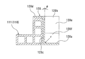
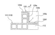
- FIG. 3 is a cross-sectional view taken along the line VV of FIG.
- FIG. 3 is a cross-sectional view taken along the line VI-VI of FIG.
- FIG. 3 is a cross-sectional view taken along the line VII-VII of FIG.
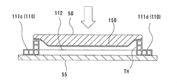
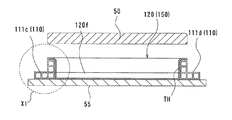
- the schematic sectional view for demonstrating the manufacturing method of the battery case for electric vehicles which concerns on 1st Embodiment.
- FIG. 11 is a cross-sectional view similar to FIG. 11 showing a first alternative of the first embodiment.
- FIG. 11 is a cross-sectional view similar to FIG. 11 showing a second alternative of the first embodiment.
- FIG. 11 is a cross-sectional view similar to FIG. 11 showing a third alternative of the first embodiment.
- FIG. 11 is a cross-sectional view similar to FIG. 11 showing a fourth alternative of the first embodiment.
- FIG. 5 is a cross-sectional view similar to FIG.
- FIG. 5 showing a primary molded member according to a second embodiment of the present invention.
- FIG. 6 is a cross-sectional view similar to FIG. 6 showing the primary molded member in the second embodiment.
- FIG. 7 is a cross-sectional view similar to FIG. 7 showing the primary molded member in the second embodiment.
- FIG. 6 is a schematic cross-sectional view for explaining the pressure molding process in the second embodiment.
- the perspective view which shows the state which attached the restraint mold used in the manufacturing method of the electric vehicle battery case which concerns on 3rd Embodiment of this invention to a frame.
- FIG. 6 is a schematic cross-sectional view for explaining a method of manufacturing a battery case for an electric vehicle according to a third embodiment.
- FIG. 6 is a schematic cross-sectional view for explaining a method of manufacturing a battery case for an electric vehicle according to a third embodiment.
- FIG. 6 is a schematic cross-sectional view for explaining a method of manufacturing a battery case for an electric vehicle according to a third embodiment.
- FIG. 6 is a schematic cross-sectional view for explaining a method of manufacturing a battery case for an electric vehicle according to a modified example of the third embodiment.
- FIG. 6 is a schematic cross-sectional view for explaining a method of manufacturing a battery case for an electric vehicle according to a fourth embodiment of the present invention.
- the electric vehicle 1 is a vehicle that travels by driving a motor with electric power supplied from the battery 30.
- the electric vehicle 1 is a vehicle that travels on electric power, and may be, for example, an electric vehicle, a plug-in hybrid vehicle, or the like.
- the type of vehicle is not particularly limited, and may be a passenger car, a truck, a work vehicle, or other mobility. In the following, a case where the electric vehicle 1 is a passenger car type electric vehicle will be described as an example.
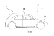
- the electric vehicle 1 is equipped with a motor, a high voltage device, or the like (not shown) on the front portion 10 of the vehicle body. Further, the electric vehicle 1 is equipped with a battery case 100 for an electric vehicle (hereinafter, also simply referred to as a battery case 100) in which the battery 30 is housed in substantially the entire surface under the floor of the vehicle interior R in the central portion 20 of the vehicle body.
- a battery case 100 for an electric vehicle (hereinafter, also simply referred to as a battery case 100) in which the battery 30 is housed in substantially the entire surface under the floor of the vehicle interior R in the central portion 20 of the vehicle body.
- FIG. 1 the front-rear direction of the electric vehicle 1 is shown in the X direction, and the height direction is shown in the Z direction. The same notation is used in the following figures, and the vehicle width direction is shown in the Y direction in FIGS. 2 and later.
- the battery case 100 is arranged inside a pair of rocker members 200 which are skeleton members in the vehicle width direction, and is supported by these rocker members 200.
- the individual rocker members 200 extend in the vehicle front-rear direction below the vehicle width direction end of the electric vehicle 1 (see FIG. 1).
- the rocker member 200 is formed by laminating a plurality of metal plates, and has a function of protecting the vehicle interior R and the battery case 100 from an impact from the side of the electric vehicle 1.
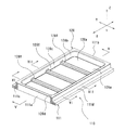
- the battery case 100 sandwiches the frame 110 that defines the through hole or the through space TH, which is an example of the space inside, the bathtub-shaped tray 120, and these from above and below. It is provided with a top cover 130 and an undercover 140 arranged in.
- the frame 110 is a frame-shaped member forming the skeleton of the battery case 100.
- the frame 110 is made of, for example, an aluminum alloy extruded product, an aluminum alloy cast product, a magnesium alloy extruded product, a magnesium alloy cast product, or a combination thereof.
- the frame 110 can be manufactured by joining a plurality of extruded hollow members of a 6000 series aluminum alloy by arc welding.
- the aluminum alloy may be 7000 series.
- the frame 110 may be a steel plate roll foam material, a steel plate pressed part, or a combination thereof. By forming the frame 110 with steel members, it is possible to increase the strength of the frame while suppressing the cost.
- the frame 110 in the present embodiment includes a rectangular frame-shaped frame-shaped body 111 in a plan view, and three cross members 112 extending in the vehicle width direction so as to cross the penetrating space TH below the frame-shaped body 111. Be prepared.
- the frame 110 having the through space TH will be described as an example, but the shape of the frame 110 is not particularly limited.
- the frame 110 may define a concave or bottomed hollow portion as a space that replaces the through space TH.
- the frame-shaped body 111 includes side walls 111c and 111d extending in the front-rear direction of the vehicle, and front walls 111a and rear walls 111b connecting them and extending in the vehicle width direction.
- the outer contours of the side walls 111c and 111d are substantially L-shaped in a cross section perpendicular to the vehicle front-rear direction.
- the interiors of the side walls 111c and 111d are hollow, respectively, partitioned into a plurality of chambers extending in the longitudinal direction. As shown in FIG.
- the outer contours of the front wall 111a and the rear wall 111b have a square tubular shape in a cross section perpendicular to the vehicle width direction, and the insides of the front wall 111a and the rear wall 111b also extend in the longitudinal direction, respectively. It is divided into multiple rooms and is hollow.
- the outer contours of the side walls 111c and 111d may have a shape other than the L-shape, such as a square cylinder, in a cross section perpendicular to the vehicle front-rear direction. Further, the side walls 111c and 111d may be solid.
- the outer contours of the front wall 111a and the rear wall 111b may have a shape other than a square cylinder shape such as an L shape in a cross section perpendicular to the vehicle width direction. Further, the front wall 111a and the rear wall 111b may be solid.
- the three cross members 112 are provided in parallel with the front wall 111a and the rear wall 111b at substantially equal intervals, and connect the side wall 111c and the side wall 111d, respectively.
- the cross member 112 has a function of improving the strength of the battery case 100.
- the cross member 112 can improve the strength of the electric vehicle 1 (see FIG. 1) against a collision from the side.
- the cross member 112 is not an essential configuration and may be omitted if necessary.
- its mode is not particularly limited, and the shape, arrangement, number, and the like can be arbitrarily set.
- the tray 120 is made of thermoplastic resin.
- the tray 120 may be made of a thermoplastic resin such as polyethylene or polypropylene that does not contain reinforcing fibers. Further, the tray 120 may be a thermoplastic fiber reinforced resin. More specifically, the thermoplastic fiber reinforced resins that can be used as the material of the tray 120 are GFRP (reinforcing fiber is glass fiber), CFRP (reinforcing fiber is carbon fiber), and CNFRP (reinforcing fiber is cellulose nanofiber). including.
- GFRP reinforcing fiber is glass fiber
- CFRP refinforcing fiber is carbon fiber
- CNFRP reinforcing fiber is cellulose nanofiber
- the tray 120 has a bottom wall 120a, a peripheral wall 120c that defines an opening 120b on the side opposite to the bottom wall 120a provided on the peripheral edge of the bottom wall 120a, that is, on the tip side, and a horizontal direction (X) provided at the tip of the peripheral wall 120c. , Y direction) and a flange 120d extending outward. That is, the tray 120 has a bathtub shape.
- the battery 30 is housed in the accommodating portion 120e, which is a space surrounded by the bottom wall 120a and the peripheral wall 120c.
- the bottom wall 120a is provided with an overhang 120f that projects toward the opening 120b and has a shape complementary to the cross member 112.
- the tray 120 is integrated with the frame 110 by caulking and joining the frame 110 by a pressure forming method.
- the bottom wall 120a of the tray 120 is located below the through space TH, and the outer surface of the peripheral wall 120c of the tray 120 is in close or pressure contact with the inner surface of the frame-shaped body 111.
- the lower surface of the overhanging portion 120f is in close or pressure contact with the cross member 112.
- the flange 120d of the tray 120 is placed on the upper surface of the frame-shaped body 111.
- the opening 120b of the tray 120 is closed by the top cover 130.
- the accommodating portion 120e in which the battery 30 is accommodated is a closed space by the bottom wall 120a of the tray 120, the peripheral wall 120c of the tray 120, and the top cover 130.
- the flange 120d of the tray 120 is fixed to the frame-shaped body 111 of the frame 110 by being fastened together with screws.
- a floor panel 300 constituting the floor surface of the vehicle interior R and a floor cross member 400 extending in the vehicle width direction in the vehicle interior R are arranged above the top cover 130.
- An undercover 140 is arranged below the tray 120.
- the undercover 140 is screwed to the frame 110 and supports the tray 120 from below.
- the top cover 130 and the undercover 140 may be fastened to other members by methods other than screws such as rivets, bolts, and adhesives.
- the tray 120 is bathtub-shaped and seamless, the sealing property can be improved, and since the frame and the tray are integrated by caulking joint by a pressure forming method without being welded, high accuracy is achieved without dimensional change due to thermal deformation. Joining has been realized. Further, since the tray 120 is made of resin as described above, the battery case 1 for an electric vehicle can be made lighter than the case where the tray 120 is made of metal. Further, since it is made of resin, the tray 120 has a high degree of freedom in shape.
- the drawing angle (inclination of the peripheral wall 120c), which is difficult in cold press forming of metal, is omitted, and the ridge line portion or the corner is formed.
- the roundness of the portion can be reduced, and the tray 120 having an arbitrary shape can be formed.
- the peripheral wall 120c is substantially orthogonal to the bottom wall 120a, and the draft angle ⁇ is 0 degrees.
- the radius r of the ridge line portion 120 g and the corner portion 120 h is about 1 mm to 20 mm, except for the portion where the R shape is applied to the inner upper portion of the frame-shaped body 111 of the frame 120.
- a flat plate (work member) 150 made of a thermoplastic resin to be a tray 120 is prepared.
- the method for manufacturing the flat plate 150 include the following. First, in the case of a thermoplastic resin containing no reinforcing fibers or GFRP, injection molding using pellets can be adopted. Further, in the case of GFRP and CFRP (short fibers), a hot press using SMC (Sheet Molding Compound) can be adopted. Further, in the case of CFRP (continuous fiber), RTM (Resin Transfer Molding) using woven fabric and resin of reinforcing fiber and PCM (Prepreg Compression) of prepreg sheet can be adopted.
- SMC Sheet Molding Compound
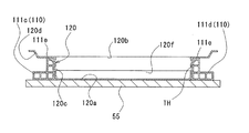
- the frame 120 is placed on the table 55 having a flat upper surface. Further, the flat plate 150 is placed on the frame 120 placed on the table 55 so as to be superposed on the frame 120. In this state, pressure is applied to the flat plate 150 from the side opposite to the frame 110 and pressed against the frame 110 to cause the flat plate 150 to bulge into the through space TH. This bulge transforms the flat plate 150 into a bathtub-shaped tray 120 having a bottom wall 120a, a peripheral wall 120c, and a flange 120d. The tray 120 is caulked to the frame 120 when deformed from the flat plate 150 by pressurization. As a result, the tray 120 and the frame 110 are integrated, as most clearly shown in FIGS. 5 to 7.
- the flat plate 150 When applying pressure to the flat plate 150 from the side opposite to the frame 110, the flat plate 150 is heated. Since the flat plate 150 has thermoplasticity, the plasticity is improved by heating. As a result, by applying pressure, the flat plate 150 can be more reliably deformed into a desired bathtub shape.
- Examples of the heating method of the flat plate 150 include the following. First, hot air may be blown onto one or both of the flat plate 150 and the frame 110. Further, the flat plate 150 and the frame 110 may be housed together with the base 55 in a heating furnace heated by a heater. Further, the frame 110 may be electromagnetically induced and heated.
- the flat plate 150 is pressurized by a pressure forming method.
- the pressure molding method refers to a method of molding a member by the pressure of gas or liquid.
- the hydraulic transfer elastic body 50 that can be elastically deformed by utilizing the pressure of the liquid is used.
- the hydraulic transfer elastic body 50 may have a structure in which only the lower surface of a metal chamber containing a liquid such as water or oil is closed with a rubber plate. By adjusting the pressure of the liquid, the rubber plate is elastically deformed, and molding can be performed without the liquid coming into direct contact with the flat plate 150.
- the battery case 100 is configured by joining the top cover 130 and the under cover 140 as shown in FIG.
- the front wall 111a, the rear wall 111b, and the side walls 111c, 111d are set to have a thicker upper portion than the other portions.
- the upper portions of the front wall 111a, the rear wall 111b, and the side walls 111c and 111d are portions that are susceptible to the force due to the molding, and the thickness of the portions is increased to prevent unintended deformation.
- the inner upper portion of the front wall 111a, the rear wall 111b, and the side walls 111c, 111d is provided with an R shape to promote the inflow of materials into the flat plate 150 in the above molding.
- the resin flat plate 150 can be formed into a bathtub-shaped tray 120 and at the same time integrated with the frame 110. Since the flat plate 150 is formed into a bathtub-shaped tray 120 by pressurization, the tray 120 has no seams and high sealing performance can be ensured. Further, since the flat plate 150 is formed into a bathtub shape and caulked to the frame 110 at the same time, the joining process can be simplified. Since the tray 120 is caulked to the frame 110 instead of being welded, thermal deformation does not occur and high-precision joining can be realized. Therefore, sufficient sealing performance of the battery case 100 can be ensured, and the tray 120 obtained by molding the flat plate 150 into a bathtub shape and the frame 110 can be easily and highly accurately joined.
- the pressure forming method for pressurizing the flat plate 150 for example, it is possible to omit the punching angle ⁇ , which is difficult in general cold press forming of a metal plate, and to reduce the roundness of the ridge line portion 120 g and the corner portion 120 h. Therefore, the degree of freedom in the shape of the bathtub-shaped tray 120 is increased. Further, by omitting the extraction angle ⁇ and reducing the roundness of the ridge line portion 120 g and the corner portion 120 h, the space efficiency of the tray 120 can be improved, and a larger capacity battery 30 can be mounted.
- the liquid to which pressure is applied does not scatter or leak. If the hydraulic transfer elastic body is not used in the pressure forming method, the flat plate 150 is directly deformed by the fluid held at high pressure, so that the outer edge of the flat plate 150 is strongly restrained so that the fluid does not scatter and leak to the outside. There is a need. However, when the hydraulic pressure transfer elastic body is used, the liquid to which the force is applied does not scatter and leak, so that the binding force of the outer edge portion of the flat plate 150 can be reduced.
- the flat plate 150 when the flat plate 150 is molded into a bathtub shape, the amount of material flowing in from the outer edge portion to the inside can be increased, cracking of the member to be molded can be suppressed, and stable processing can be realized. Further, since it is not necessary to completely seal the outer edge portion of the flat plate 150, the maintenance of the press machine can be facilitated and the productivity can be improved.
- the negative angle forming is performed so as to form a negative angle at least partially from the bottom wall 120a of the tray 120 toward the opening 120b.
- the negative angle is a term often used in the field of molding using a mold, and indicates that the punching angle of the mold in the molding member is less than zero (minus).
- the frame-shaped body 111 of the frame 110 and the flat plate 150 which did not have a negative angle portion in advance, are integrally deformed to form a negative angle by the pressurization from the hydraulic pressure transmission elastic body 50.
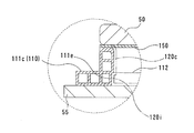
- negative angle molding is performed. Specifically, the inner surface of the frame-shaped body 111 is deformed outward for each room, and the peripheral wall 120c of the tray 120 is also deformed outward to form the negative angle portions 111e and 120i.
- the negative angle portions 111e and 120i are formed, so that the negative angle portions 111e and 120i release the caulking joint of the tray 120 to the frame 110. Can be suppressed. Therefore, the negative angle molding increases the joint strength between the frame 110 and the bathtub-shaped tray 120.
- negative angle forming is peculiar to the pressure forming method because it is necessary to add a cam mechanism in cold press forming that requires a punching angle using a normal die, and the die structure becomes complicated. It is the molding of.
- a negative angle portion 111e is formed in advance on the frame-shaped body 111 of the frame 110.
- the negative angle forming is performed by pressing the flat plate 150 against the negative angle portion 111e of the frame-shaped body 111 formed in advance.
- a negative angle portion 111e is provided as a recess at a position on the lower end side in the view of the inner surface of the frame-shaped body 111.
- a negative angle portion 111e is provided as a recess at a position intermediate in the height direction in the view of the inner surface of the frame-shaped body 111.
- the inner surface of the frame-shaped body 111 is inclined toward the center of the frame 110, so that the negative angle portion 111e is formed as the inclined surface.
- the negative angle portion may also be formed on the cross member 112.
- the structure of the finally manufactured battery case 100 is the same as that of the first embodiment, except as otherwise specified. Further, the method for manufacturing the battery case in these embodiments is also the same as that in the first embodiment, except for the points particularly mentioned.
- a primary molded product (work member) 160 made of a thermoplastic resin having a bathtub shape close to the finished tray 120 is prepared.
- the primary molded product 160 includes a bottom wall 160a, a peripheral wall 160b provided on the peripheral edge of the bottom wall 160a, and a flange 160c provided at the tip of the peripheral wall 160b.
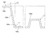
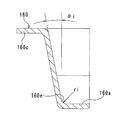
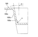
- the punching angle ⁇ i of the primary molded product 160 is not 0 degrees, unlike the punching angle ⁇ (FIGS. 5 to 7) of the tray 120 of the finished product.
- the peripheral wall 120c of the finished product tray 120 is not inclined, whereas the peripheral wall 160b of the primary molded product 160 is inclined.
- the radius ri of the ridge portion 160d and the corner portion 160e of the primary molded product 160 is about 5 mm to 70 mm, which is larger than the radius r of the ridge portion 120 g and the corner portion 120h (FIGS. 5 to 7) in the tray 120 of the finished product. large.
- the manufacturing method of the primary molded product 160 is as follows. First, in the case of a thermoplastic resin containing no reinforcing fibers or GFRP, injection molding using pellets can be adopted. Further, in the case of GFRP and CFRP (short fibers), a hot press using SMC can be adopted. Further, in the case of CFRP (continuous fiber), RTM using woven fabric and resin of reinforcing fiber or PCM of prepreg sheet can be adopted.
- the primary molded product 160 is superposed on the frame 110 so that the flange 160c is arranged on the upper surface of the frame-shaped body 111 of the frame 110 and the bottom wall 160a and the peripheral wall 160b are located in the through space TH.
- pressure is applied to the primary molded product 160 from the side opposite to the frame 110 by a pressure molding method using the hydraulic pressure transfer elastic body 50, and the primary molded product 160 is pressed against the frame 110. Inflate in the penetration space TH.
- the primary molded product 160 is deformed into a bathtub-shaped tray 120, and the tray 120 is caulked and joined to the frame 110.
- the primary molded product 160 preformed into the same shape as the tray 120 is subjected to deformation into a bathtub-shaped tray 120 by applying pressure and caulking joint to the frame 110. That is, the transformation to the tray 120 is performed step by step in two steps. Therefore, the amount of strain applied to the primary molded product 160 is reduced as compared with the case where the tray 120 is deformed and caulked to the frame 110 only by applying pressure to the flat plate, so that the local wall thickness is reduced. The decrease can be suppressed.
- a restraint mold 60 that restrains the position of the frame 110 when the flat plate 150 is pressed by the pressure forming method is used.
- the restraint mold 60 can also be used when the target of pressurization by the pressure molding method is the primary molded product 160 of the second embodiment.
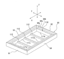
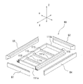
- the restraint mold 60 has a shape complementary to the frame 110 and is arranged outside the frame 110.
- the restraint mold 60 includes a front restraint member 61 and a rear restraint member 62 that support the front wall 111a and the rear wall 111b, respectively, and side restraint members 63 and 64 that support the side walls 111c and 111d, respectively.
- the front restraint member 61, the rear restraint member 62, and the side restraint members 63 and 64 are combined to form a frame shape in a plan view.
- the upper surface of the restraint mold 60 has a two-stage shape.
- the upper surface of the restraint mold 60 has a first surface 60a aligned at substantially the same height as the upper surface of the frame 110, and a second surface 60b provided one step higher than the upper surface of the frame 110. ..
- the first surface 60a and the second surface 60b are connected by an inclined surface 60c, and the second surface 60b is arranged outside the first surface 60a in a plan view.
- the lower surfaces of the frame 110 and the restraint mold 60 are aligned. Therefore, when comparing the height dimensions of the frame 110 and the restraint mold 60, the height of the restraint mold 60 is set to be larger than the height of the frame 110.
- a restraint mold 60 for restraining the movement of the frame 110 is further prepared, and the restraint mold 60 is fixed to the outside of the frame 110 in a plan view. (See FIG. 20). After that, as shown in FIGS. 22 to 24, the flat plate 150 is transformed into a bathtub-shaped tray 120 and integrated with the frame 110 as in the first embodiment.
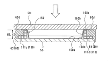
- the flat plate 150 is arranged on the restraint mold 60, and as shown in FIG. 23, the flat plate 150 is pressurized via the hydraulic pressure transfer elastic body 50 to form the first flat plate 150.
- the outer edge portion 150a (the portion slightly inner from the outermost edge portion) is supported by the frame 110, and the second outer edge portion 150b (outermost edge portion) outside the first outer edge portion 150a is supported by the second surface 60b of the restraint mold 60. Supported by.
- the flat plate 150 is bent and arranged so that the height decreases from the outside to the inside, and the flat plate 150 is continuously pressed from the bent state to make the flat plate 150 bathtub-like. It can be deformed into the tray 120 of the above and can be stably caulked and joined to the frame 110.
- the flat plate 150 is pressurized in a state where the flat plate 150 is bent so that the height decreases from the outside to the inside, the amount of material flowing into the flat plate 150 is increased and the tray 120 is used. The roundness of the ridgeline or the corner of the bottom portion 122a can be further reduced.
- the shape of the restraint mold 60 is changed. Specifically, the upper portion 60d of the restraint mold 60 in this modification is flat. Further, the height H1 of the restraint mold 60 is set to be the same as the height H2 of the frame 110. In particular, when there is no problem in moldability when transforming the flat plate 150 into the tray 120 (see FIG. 3), the heights H1 and H2 of the restraint mold 60 and the tray 120 can be made the same as in this modification. , The width of the flange 120d (see FIG. 3) of the tray 120 can be minimized. As a result, the material yield of the resin flat plate 150 can be improved.
- a primary molded product 160 (see FIGS. 16 to 18) made of a thermoplastic resin having a bathtub shape described in the second embodiment is subjected to a pressure molding method using a hydraulic pressure transfer elastic body 50.
- the restraint mold 60 can be used when transforming into the tray 120 (see FIG. 3). In this case, the heights H1 and H2 of the restraint mold 60 and the tray 120 are set to be the same as in the modified example (FIG. 25) of the third embodiment described above.
- FIG. 2 In the cross-sectional view (FIG. 2, FIG. 5 to FIG. 15, FIG. 19, FIG. 22 to FIG. 26) showing the frame-shaped body 111 of the frame 120 referred to in the above description, the R shape is shown except for the above-mentioned inner upper part. Absent. However, all the corners of the frame-shaped body 111 may be appropriately R-shaped.
Landscapes
- Engineering & Computer Science (AREA)
- Chemical & Material Sciences (AREA)
- General Chemical & Material Sciences (AREA)
- Electrochemistry (AREA)
- Chemical Kinetics & Catalysis (AREA)
- Mechanical Engineering (AREA)
- Transportation (AREA)
- Power Engineering (AREA)
- Sustainable Energy (AREA)
- Sustainable Development (AREA)
- Life Sciences & Earth Sciences (AREA)
- Composite Materials (AREA)
- Aviation & Aerospace Engineering (AREA)
- Textile Engineering (AREA)
- Combustion & Propulsion (AREA)
- Arrangement Or Mounting Of Propulsion Units For Vehicles (AREA)
- Battery Mounting, Suspending (AREA)
Abstract
電動車両用バッテリーケース100の製造方法では、内側に貫通空間THを画定するフレームと、樹脂製の平板150とを準備し、平板150をフレーム110に重ねて配置し、フレーム110とは反対側から平板150に圧力を加え、フレーム110に平板150を押付けて貫通空間TH内で膨出させ、それによって平板150を、底壁120aと、底壁120aの周縁に設けられて開口部120bを画定する周壁120cとを備えるバスタブ状のトレイ120に変形させると共に、フレーム110にかしめ接合する。
Description
本発明は、電動車両用バッテリーケースの製造方法および電動車両用バッテリーケースに関する。
電気自動車などの電動車両は、十分な航続距離を確保するために大容量のバッテリーを搭載する必要がある一方で広い車室が求められている。これらの要求を両立するため、多くの電気自動車では大容量のバッテリーをバッテリーケースに格納して車両の床下全面に搭載している。従って、電動車両用バッテリーケースには、路面などからの水の浸入を防止して電子部品の不具合を防止するための高いシール性が求められるとともに、内部のバッテリーを保護するために高い衝突強度が求められる。
例えば、特許文献1には、金属板を冷間プレス成形によりバスタブ状に成形したトレイを用いることでシール性を向上させたバッテリーケースが開示されている。また、特許文献2には、バッテリーケースの底板とフレームとを溶接などの接合手段で接合することにより、スペース効率および衝突強度を向上させたバッテリーケースが開示されている。
特許文献1のバッテリーケースでは、金属板を冷間プレス成形でバスタブ状に成形するため、金型の抜き角(側面の傾斜)および底部の稜線部ないし角部に丸みが必要となり、バッテリー搭載用のスペース効率を向上できない。また、バスタブ状のトレイと、フレームである縦骨とを溶接などによって別途接合する必要もある。
特許文献2のバッテリーケースでは、溶接などの接合手段に伴って熱変形が生じるおそれがある。そのため、シール精度および接合精度などに関して検査工程および修繕工程を追加する必要がある。
本発明は、電動車両用バッテリーケースおよびその製造方法において、十分なシール性を確保するとともに簡易かつ高精度の接合を実現することを課題とする。
本発明の第1の態様は、内側に空間を画定するフレームと、樹脂製の被成形部材とを準備し、前記被成形部材を前記フレームに重ねて配置し、前記フレームとは反対側から前記被成形部材に圧力を加え、前記フレームに前記被成形部材を押付けて前記空間内で膨出させ、それによって前記被成形部材を、底壁と、前記底壁の周縁に設けられて開口部を画定する周壁とを備えるバスタブ状のトレイに変形させると共に、前記フレームと一体化することを含む、電動車両用バッテリーケースの製造方法を提供する。
この方法によれば、樹脂製の被成形部材をバスタブ状のトレイに成形すると同時にフレームと一体化することができる。被成形部材は加圧によりバスタブ状のトレイに成形されるため、トレイに継ぎ目が存在せず、高いシール性を確保できる。また、被成形部材のバスタブ状への成形と、フレームへのかしめ接合とが同時になされるため、接合工程を簡易化できる。トレイは、フレームに対して溶接によらずに一体化されるため、熱変形が生じることもなく、高精度の接合を実現できる。従って、バッテリーケースの十分なシール性を確保するとともに、被成形部材をバスタブ状に成形したトレイとフレームとを簡易かつ高精度に接合できる。
トレイは、樹脂製の被成形部材をバスタブ状に成形することで得られる。つまり、トレイは樹脂製である。トレイを樹脂製とすることで、トレイが金属製である場合と比較して、電動車両用バッテリーケースをより軽量化できる。また、被成形部材は樹脂製であるため、トレイの形状の自由度が高い。
前記トレイは前記周壁の先端に設けられたフランジをさらに備えてもよい。
前記被成形部材を構成する前記樹脂は熱可塑性を有し、前記フレームとは反対側から前記被成形部材に圧力を加える際に、前記被成形部材を加熱してもよい。
前記被成形部材の加熱は、前記被成形部材自体の加熱及び前記フレームの加熱のうちの少なくともいずれか一方により実行されてもよい。
前記被成形部材は平板状であってもよい。
電動車両用バッテリーケースの製造方法は、底壁と、前記底壁の周縁に設けられた周壁と、前記周壁の先端に設けられたフランジとを有する前記被成形部材を一次成形することをさらに備えてもよい。
この方法によれば、トレイと同様の形状、つまり底壁、周壁、及びフランジを有する形状に一次成形された被成形部材が、圧力を加えることによるバスタブ状のトレイへの変形とフレームに対するかしめ接合に供される。つまり、被成形部材のトレイへの変形は2工程に分けて段階的に行われる。そのため、平板状の被成形部材に圧力を加えることのみで、トレイに変形させ、かつフレームにかしめ接合する場合と比較して、被成形部材に加えられる歪量が低減されるので、局所的な肉厚減少を抑制することができる。
前記樹脂は繊維強化樹脂であり、前記被成形部材の前記一次成形は射出成形であってもよい。
前記樹脂は繊維強化樹脂であり、前記被成形部材の前記一次成形はSMCの熱プレスであってもよい。
前記フレームは金属製であってもよい。
前記フレームとは反対側から前記被成形部材へ圧力を加えることは、圧力成形法により実行されてもよい。
圧力成形法を採用することで、例えば金属板の一般的な冷間プレス成形では困難な抜き角(側面の傾斜)の省略と、稜線部ないし角部の丸みの低減とが可能となり、バスタブ状のトレイの形状の自由度が高くなる。また、抜き角の省略と、稜線部の丸みの低減によって、トレイのスペース効率を向上でき、より大容量のバッテリーを搭載できる。ここで、圧力成形法は、気体または液体の圧力によって部材を成形する方法のことをいう。
前記フレームとは反対側から前記被成形部材へ圧力を加えることは、液体の圧力を利用して弾性変形可能な液圧伝達弾性体を準備し、前記フレームに重ねて配置された前記被成形部材に、前記液圧伝達弾性体を重ねて配置し、前記液圧伝達弾性体を介して前記被成形部材に圧力を加えてもよい。
この方法によれば、被成形部材をバスタブ状に成形する際、圧力を加える液体が飛散および漏出しない。ここで、例えば、液圧伝達弾性体は、液体の入った金属製のチャンバーの下面のみがゴム板で塞がれている構造を有するものであり得る。液体の圧力を調整することにより、ゴム板が弾性変形し、液体が被成形部材と直接接触することなく成形を行うことができる。仮に、圧力成形法において液圧伝達弾性体を使用しない場合、高圧に保持される流体で直接被成形部材を変形させるため、流体が外部に飛散および漏出しないように被成形部材の外縁部を強く拘束する必要がある。しかし、液圧伝達弾性体を使用すると、力を加える液体が飛散および漏出しないため、被成形部材の外縁部の拘束力を低減できる。そのため、被成形部材をバスタブ状に成形する際に外縁部から内側への材料流入量を増加させることができ、被成形部材の割れなど抑制して安定した加工を実現できる。また、被成形部材の外縁部を完全にシールする必要がなくなることから、外縁部を拘束する金型およびプレス機のメンテナンスが容易になり、生産性を向上できる。
前記フレームとは反対側から前記被成形部材に圧力を加えて前記被成形部材を前記トレイに変形させる際に、前記トレイの前記底壁から前記開口部に向かって少なくとも部分的に負角を形成する負角成形が行われてもよい。
この方法によれば、被成形部材をバスタブ状のトレイに成形する際に、負角が形成されるので、負角部分によってフレームに対するトレイのかしめ接合が外れることを抑制できる。ここで、負角とは、金型を用いた成形分野においてよく使用される用語であり、成形部材における金型の抜き角がゼロ未満(マイナス)であることを示す。従って、負角成形によって、フレームとバスタブ状のトレイの接合強度が増大する。特に、負角成形は、通常の金型を使用した抜き角を要する冷間プレス成形ではカム機構を追加する必要があり、金型構造が複雑になるなどの問題があり、圧力成形法に特有の成形である。
前記フレームは、予め負角が形成された負角部を有し、前記負角成形は、前記フレームとは反対側から前記被成形部材に圧力を加えて前記被成形部材を前記トレイに変形させる際に、前記被成形部材を前記フレームの前記負角部に押し付けることにより行われてもよい。
この方法によれば、フレームの負角部によって、容易かつ確実に負角成形を実行できる。
前記負角成形は、前記フレームとは反対側から前記被成形部材に圧力を加えて前記被成形部材を前記トレイに変形させる際に、前記フレームと前記被成形部材とが一体的に変形して前記負角を形成することによりなされてもよい。
この方法によれば、被成形部材とフレームが一体的に変形することで負角を形成するため、予めフレームに対して負角部を設ける必要がない。従って、簡易に負角成形を実行できる。
本発明の第2の態様は、内側に空間を画定する金属製のフレームと、前記空間内に位置する底壁と、前記底壁の周囲に設けられて前記底壁とは反対側に開口部を画定する周壁と、前記周壁の先端に設けられたフランジとを備え、前記フレームにかしめ接合された、樹脂製でバスタブ状のトレイとを備える、電動車両用バッテリーケースを提供する。
この構成によれば、トレイはバスタブ状で継ぎ目がないのでシール性を向上でき、フレームとトレイが溶接されることなく一体化されているため、熱変形による寸法変化が生じることなく高精度の接合が実現されている。また、トレイは樹脂製であるので、トレイが金属製である場合と比較して、電動車両用バッテリーケースをより軽量化できる。さらに、樹脂製であるため、トレイの形状の自由度が高い。
前記トレイの前記底壁から開口部に向かって少なくとも部分的に内側へ向かう負角が形成された負角部が設けられてもよい。
トレイに負角部が形成されていることによって、かしめ接合が外れることを抑制でき、電動車両用バッテリーケースの強度を向上できる。
前記トレイは繊維強化樹脂製であってもよい。
繊維強化樹脂製とすることで、トレイの軽量化は確保しつつ、トレイの強度を向上できる。
前記フレームは、アルミ合金押出品、アルミ合金鋳造品、マグネシウム合金押出品、マグネシウム合金鋳造品、またはそれらの組み合わせからなってもよい。
フレームをアルミ系またはマグネシウム系の材料製とすることで、強度を確保しつつフレームの軽量化を図ることができる。
前記フレームは、鋼板ロールフォーム材、鋼板プレス部品、またはそれらの組み合わせからなってもよい。
鋼製の部材でフレームを構成することで、コストを抑制しつつ、フレームの高強度化を図ることができる。
前記フレームはクロスメンバーを備えてもよい。
フレームがクロスメンバーを備えることで、電動車両用バッテリーケースの強度を向上させることができる。特に、クロスメンバーによって、車両の側方からの衝突に対する強度を向上できる。
本発明によれば、電動車両用バッテリーケースおよびその製造方法において、十分なシール性を確保するとともに簡易かつ高精度の接合を実現できる。
(第1実施形態)
図1を参照して、電動車両1は、バッテリー30から供給される電力によってモータを駆動させて走行する車両である。電動車両1は、電力で走行する車両であり、例えば、電気自動車またはプラグインハイブリッド車等であり得る。車両の種類については、特に限定されず、乗用車、トラック、作業車、またはその他のモビリティ等であり得る。以下では、電動車両1が乗用車タイプの電気自動車である場合を例に挙げて説明する。
図1を参照して、電動車両1は、バッテリー30から供給される電力によってモータを駆動させて走行する車両である。電動車両1は、電力で走行する車両であり、例えば、電気自動車またはプラグインハイブリッド車等であり得る。車両の種類については、特に限定されず、乗用車、トラック、作業車、またはその他のモビリティ等であり得る。以下では、電動車両1が乗用車タイプの電気自動車である場合を例に挙げて説明する。
電動車両1は、車体前部10に不図示のモータや高電圧機器等を搭載している。また、電動車両1は、車体中央部20の車室Rの床下の概ね全面にバッテリー30を格納した電動車両用バッテリーケース100(以下、単にバッテリーケース100ともいう。)を搭載している。なお、図1中、電動車両1の前後方向をX方向で示し、高さ方向をZ方向で示している。以降の図でも同表記とし、図2以降で車幅方向をY方向で示す。
図2を参照して、バッテリーケース100は、車幅方向において、骨格部材である一対のロッカー部材200の内側に配置され、これらのロッカー部材200に支持されている。個々のロッカー部材200は、電動車両1(図1参照)の車幅方向端部の下方において車両前後方向に延びている。ロッカー部材200は、複数枚の金属板が張り合わされて形成されており、電動車両1の側方からの衝撃に対して車室Rおよびバッテリーケース100を保護する機能を有する。
図3から図7を併せて参照して、バッテリーケース100は、内側に空間の一例である貫通孔ないし貫通空間THを画定するフレーム110と、バスタブ状のトレイ120と、これらを上下から挟み込むように配置されるトップカバー130およびアンダーカバー140とを備える。
フレーム110は、バッテリーケース100の骨格をなす枠状の部材である。フレーム110は、例えば、アルミ合金押出品、アルミ合金鋳造品、マグネシウム合金押出品、マグネシウム合金鋳造品、またはそれらの組み合わせからなる。フレーム110をアルミ系またはマグネシウム系の材料製とすることで、強度を確保しつつフレームの軽量化を図ることができる。特に、フレーム110は、6000系のアルミ合金の複数の押出中空部材をアーク溶接で接合することで製作できる。この場合、アルミ合金は7000系であってもよい。
フレーム110は、鋼板ロールフォーム材、鋼板プレス部品、またはそれらの組み合わせであってもよい。鋼製の部材でフレーム110を構成することで、コストを抑制しつつ、フレームの高強度化を図ることができる。
複数の部材を接合してフレーム110を製作する場合、前述のアーク溶接以外に、摩擦攪拌接合、FSW(Friction Stir Welding)、レーザー溶接、電子ビーム溶接、抵抗スポット溶接、SPR(Self Piercing Rivet)、FDS(Flow Drill Screw)のような材料に適した手段を採用できる。
本実施形態におけるフレーム110は、平面視において矩形枠状の枠状体111と、枠状体111内の下方において貫通空間THを横切るように車幅方向に延びて3本のクロスメンバー112とを備える。なお、本実施形態では、貫通空間THを有するフレーム110を例に説明するが、フレーム110の形状は特に限定されない。例えば、フレーム110は、貫通空間THに代わる空間として凹形状ないし有底形状の中空部を画定するものでもよい。
枠状体111は、車両前後方向に延びる側壁111c,111dと、それらを接続して車幅方向に延びる前壁111aおよび後壁111bとを備える。図6および図7に示すように、側壁111c,111dの外形輪郭は、車両前後方向に垂直な断面において概略L字形をしている。側壁111c,111dの内部は、それぞれ長手方向に延びる複数の部屋に仕切られて中空状となっている。図5に示すように、前壁111aおよび後壁111bの外形輪郭は、車幅方向に垂直な断面において四角筒状であり、前壁111aおよび後壁111bの内部も同様にそれぞれ長手方向に延びる複数の部屋に仕切られて中空状となっている。側壁111c,111dの外形輪郭は、車両前後方向に垂直な断面において、例えば四角筒状のようなL字形以外の形状であってもよい。また、側壁111c,111dは中実であってもよい。前壁111aおよび後壁111bの外形輪郭は、車幅方向に垂直な断面において、例えばL字形状のような四角筒状以外の形状であってもよい。また、前壁111aおよび後壁111bは、中実であってもよい。
3本のクロスメンバー112は、前壁111aおよび後壁111bと平行にほぼ等間隔で設けられ、それぞれ側壁111cと側壁111dを接続している。クロスメンバー112は、バッテリーケース100の強度を向上させる機能を有する。特に、クロスメンバー112によって、電動車両1(図1参照)の側方からの衝突に対しての強度を向上できる。ただし、クロスメンバー112は、必須の構成ではなく、必要に応じて省略されてもよい。また、クロスメンバー112を設置する場合にも、その態様は特に限定されず、形状、配置、および本数等は任意に設定され得る。
トレイ120は熱可塑性樹脂製である。トレイ120は、強化繊維を含まないポリエチレン、ポリプロピレンのような熱可塑性樹脂製であってもよい。また、トレイ120は熱可塑性の繊維強化樹脂であってもよい。より具体的には、トレイ120の材料として採用し得る熱可塑性の繊維強化樹脂は、GFRP(強化繊維はグラスファイバー)、CFRP(強化繊維はカーボンファイバー)、およびCNFRP(強化繊維はセルロースナノファイバー)を含む。トレイ120を繊維強化樹脂製とすることで、トレイ120の軽量化は確保しつつ、トレイ120の強度を向上できる。
トレイ120は、底壁120aと、底壁120aの周縁に設けられた底壁120aと反対側つまり先端側に開口部120bを画定する周壁120cと、周壁120cの先端に設けられた水平方向(X,Y方向)に延びて外側に広がるフランジ120dとを備える。つまり、トレイ120はバスタブ状である。底壁120aと周壁120cによって囲まれた空間である収容部120eに、バッテリー30が収容される。底壁120aには、開口部120bに向けて突出し、クロスメンバー112に対して相補的な形状を有する張出部120fが設けられている。
図2、図3、および図5から図7を参照して、後に詳述するように、トレイ120はフレーム110に対して圧力成形法でかしめ接合されることで、フレーム110に対して一体化されている。具体的には、トレイ120の底壁120aは貫通空間THの下部に位置し、トレイ120の周壁120cの外面が枠状体111の内面に対して密接ないし圧接されている。また、張出部120fの下面がクロスメンバー112に対して密接ないし圧接されている。トレイ120のフランジ120dは枠状体111の上面に載置されている。
図2を参照して、トレイ120の開口部120bはトップカバー130によって閉じられている。言い換えれば、バッテリー30が収容された収容部120eは、トレイ120の底壁120a、トレイ120の周壁120c、及びトップカバー130によって閉鎖空間とされている。トップカバー130はトレイ120のフランジ120dは、フレーム110の枠状体111に対してねじで共締めされて固定されている。トップカバー130の上方には、車室Rの床面を構成するフロアパネル300と、車室Rにおいて車幅方向に延びるフロアクロスメンバー400とが配置されている。また、トレイ120の下方には、アンダーカバー140が配置されている。アンダーカバー140は、フレーム110にねじ止めされ、トレイ120を下方から支持している。トップカバー130とアンダーカバー140の他の部材への締結は、リベット、ボルト、接着剤のようなねじ以外の方法によるものでもよい。
トレイ120はバスタブ状で継ぎ目がないのでシール性を向上でき、フレームとトレイが溶接されることなく圧力成形法でかしめ接合によって一体化されているため、熱変形による寸法変化が生じることなく高精度の接合が実現されている。また、前述のようにトレイ120は樹脂製であるので、トレイ120が金属製である場合と比較して、電動車両用バッテリーケース1をより軽量化できる。さらに、樹脂製であるため、トレイ120の形状の自由度が高い。
図5から図7を参照して、トレイ120は圧力成形法でかしめ接合されているため、例えば金属の冷間プレス成形では困難な抜き角(周壁120cの傾斜)の省略と、稜線部ないし角部の丸みの低減とを可能とし、任意形状のトレイ120を成形できる。具体的には、本実施形態の場合、周壁120cはいずれも底壁120aに対して概ね直交しており、抜き角θは0度である。また、本実施形態の場合、フレーム120の枠状体111の内側上部のR形状が施されている部分を除き、稜線部120gと角部120hのアールrは1mm~20mm程度である。このようにトレイ120における抜き角θの省略と、稜線部120gと角部120hの丸みの低減とによって、バッテリーケース100のスペース効率を向上でき、より大容量のバッテリー30を搭載できる。
次に、図8から図11を参照し、本実施形態のバッテリーケース100の製造方法を説明する。
図8を参照して、完成品ではトレイ120となる熱可塑性樹脂からなる平板(被加工部材)150を準備する。平板150の製造方法としては、例えば以下がある。まず、強化繊維を含まない熱可塑性樹脂、またはGFRPの場合、ペレットを使用した射出成形を採用できる。また、GFRP、CFRP(短繊維)の場合、SMC(Sheet Molding Compound)を使用した熱プレスを採用できる。さらに、CFRP(連続繊維)の場合、強化繊維の織物と樹脂を使用したRTM(Resin Transfer Molding)や、プリプレグシートのPCM(Prepreg Compression)を採用できる。
次いで、図9から図11を参照して、フレーム120を上面が平坦な台55に載置する。また、台55に載置されたフレーム120に平板150を重ねて配置する。この状態で、フレーム110とは反対側から平板150に圧力を加えてフレーム110に押し付け、平板150を貫通空間TH内に膨出させる。この膨出によって平板150を、底壁120a、周壁120c、およびフランジ120dを備えるバスタブ状のトレイ120に変形させる。トレイ120は、加圧によって平板150から変形される際に、フレーム120にかしめ接合される。これにより、トレイ120とフレーム110が、図5から図7に最も明瞭に示すように、一体化する。
フレーム110とは反対側から平板150に圧力を加える際には、平板150を加熱する。平板150は熱可塑性を有するので、加熱することで塑性が向上する。その結果、圧力を加えることで、平板150がより確実に所望のバスタブ形状に変形させることができる。平板150の加熱方法としては、例えば以下がある。まず、平板150とフレーム110の一方または両方に熱風を吹き付けてもよい。また、平板150とフレーム110を台55と共に、ヒータにより高温となった加熱炉内に収容してもよい。さらに、フレーム110を電磁誘導加熱してもよい。
本実施形態では、平板150の加圧は、圧力成形法によって行われる。ここで、圧力成形法は、気体または液体の圧力によって部材を成形する方法のことをいう。本実施形態では、圧力成形法において、液体の圧力を利用して弾性変形可能な液圧伝達弾性体50を使用する。液圧伝達弾性体50は、詳細を図示しないが、例えば、水または油などの液体が入った金属製のチャンバーの下面のみがゴム板で塞がれている構造を有するものであり得る。液体の圧力を調整することにより、ゴム板が弾性変形し、液体が平板150と直接接触することなく成形を行うことができる。
図10を参照して、平板150がバスタブ状のトレイ120に変形した後に、図示しないプレス機械の加圧力を解放すると、液圧伝達弾性体50が自然状態の形状に復元する。従って、トレイ120の内部から液圧伝達弾性体50を容易に取り除くことができる。液圧伝達弾性体50を取り除いた後、図2に示すようにトップカバー130とアンダーカバー140を接合することでバッテリーケース100が構成される。
なお、本実施形態では、前壁111a、後壁111b、および側壁111c,111dは、上部の肉厚が他の部分よりも厚く設定されている。前壁111a、後壁111b、および側壁111c,111dの上部は、上記成形によって力を受けやすい部分であり、当該部分の肉厚を厚くすることで意図しない変形を防止している。また、前壁111a、後壁111b、および側壁111c,111dの内側上部には、R形状が施されており、上記成形において平板150の内側への材料流入を促すようにしている。
本実施形態の製造方法では、樹脂製の平板150をバスタブ状のトレイ120に成形すると同時にフレーム110と一体化することができる。平板150は加圧によりバスタブ状のトレイ120に成形されるため、トレイ120に継ぎ目が存在せず、高いシール性を確保できる。また、平板150のバスタブ状への成形と、フレーム110へのかしめ接合とが同時になされるため、接合工程を簡易化できる。トレイ120は、フレーム110に対して溶接ではなくかしめ接合されるため、熱変形が生じることもなく、高精度の接合を実現できる。従って、バッテリーケース100の十分なシール性を確保するとともに、平板150をバスタブ状に成形したトレイ120とフレーム110とを簡易かつ高精度に接合できる。
平板150の加圧に圧力成形法を採用することで、例えば金属板の一般的な冷間プレス成形では困難な抜き角θの省略と、稜線部120gと角部120hの丸みの低減とが可能となり、バスタブ状のトレイ120の形状の自由度が高くなる。また、抜き角θの省略と、稜線部120gと角部120hの丸みの低減によって、トレイ120のスペース効率を向上でき、より大容量のバッテリー30を搭載できる。
平板150の加圧に液圧伝達弾性体を使用した圧力成形法を採用することで、圧力を加える液体が飛散および漏出しない。仮に、圧力成形法において液圧伝達弾性体を使用しない場合、高圧に保持される流体で直接平板150を変形させるため、流体が外部に飛散および漏出しないように平板150の外縁部を強く拘束する必要がある。しかし、液圧伝達弾性体を使用すると、力を加える液体が飛散および漏出しないため、平板150の外縁部の拘束力を低減できる。そのため、平板150をバスタブ状に成形する際に外縁部から内側への材料流入量を増加させることができ、被成形部材の割れなど抑制して安定した加工を実現できる。また、平板150の外縁部を完全にシールする必要がなくなることから、プレス機のメンテナンスが容易になり、生産性を向上できる。
図12から図15は、本実施形態の変形例を示す。これらの変形例は、後述する第2および第3実施形態にも適用できる。
図12に示す変形例では、平板150をバスタブ状のトレイ120に成形する際、トレイ120の底壁120aから開口部120bに向かって少なくとも部分的に負角を形成する負角成形が行われる。ここで、負角とは、金型を用いた成形分野においてよく使用される用語であり、成形部材における金型の抜き角がゼロ未満(マイナス)であることを示す。この変形例では、液圧伝達弾性体50からの加圧によって、予め負角部分を有していなかったフレーム110の枠状体111と平板150とが一体的に変形して負角を形成することにより負角成形がなされる。具体的には、枠状体111の内面が部屋ごとに外側へ変形し、トレイ120の周壁120cも外側へ変形し、負角部111e,120iが形成される。
図12の変形例では、平板150をバスタブ状のトレイ120に成形する際に、負角部111e,120iが形成されるので、負角部111e,120iによってフレーム110に対するトレイ120のかしめ接合が外れることを抑制できる。従って、負角成形によって、フレーム110とバスタブ状のトレイ120の接合強度が増大する。特に、負角成形は、通常の金型を使用した抜き角を要する冷間プレス成形ではカム機構を追加する必要があり、金型構造が複雑になるなどの問題があり、圧力成形法に特有の成形である。
図13から図15の変形例では、フレーム110の枠状体111に負角部111eが予め形成されている。この場合、負角成形は、平板150を予め形成されている枠状体111の負角部111eに押し付けることにより行う。図13の変形例では枠状体111の内面の図において下端側の位置に窪みとして負角部111eを設けている。図14の変形例では枠状体111の内面の図において高さ方向中間の位置に窪みとして負角部111eを設けている。図15の変形例では枠状体111の内面がフレーム110の中央に向かって傾斜することにより、傾斜面として負角部111eを構成している。このように、フレーム110の枠状体111に負角部111eを予め設けることによって、容易かつ確実に負角成形を実行できる。負角部はクロスメンバー112にも形成されていてもよい。
以下、本発明の第2及び第3実施形態を説明する。これらの実施形態において、最終的に製造されるバッテリーケース100の構造は、特に言及する点を除いて、第1実施形態と同様である。また、これらの実施形態におけるバッテリーケースの製造方法も、特に言及する点を除いて、第1実施形態と同様である。
(第2実施形態)
図16から図18を参照して、本実施形態におけるバッテリーケース100の製造方法では、完成品であるトレイ120に近いバスタブ形状を有する熱可塑性樹脂製の一次成形品(被加工部材)160を準備する。本実施形態では、一次成形品160は、底壁160aと、底壁160aの周縁に設けられた周壁160bと、周壁160bの先端に設けられたフランジ160cとを備える。一次成形品160の抜き角θiは完成品のトレイ120の抜き角θ(図5から図7)とは異なり0度ではない。つまり、完成品のトレイ120では周壁120cは傾斜していないのに対して、一次成形品160の周壁160bは傾斜を有する。また、一次成形品160の稜線部160dと角部160eのアールriは5mm~70mm程度であり、完成品のトレイ120における稜線部120gと角部120hのアールr(図5から図7)よりも大きい。
図16から図18を参照して、本実施形態におけるバッテリーケース100の製造方法では、完成品であるトレイ120に近いバスタブ形状を有する熱可塑性樹脂製の一次成形品(被加工部材)160を準備する。本実施形態では、一次成形品160は、底壁160aと、底壁160aの周縁に設けられた周壁160bと、周壁160bの先端に設けられたフランジ160cとを備える。一次成形品160の抜き角θiは完成品のトレイ120の抜き角θ(図5から図7)とは異なり0度ではない。つまり、完成品のトレイ120では周壁120cは傾斜していないのに対して、一次成形品160の周壁160bは傾斜を有する。また、一次成形品160の稜線部160dと角部160eのアールriは5mm~70mm程度であり、完成品のトレイ120における稜線部120gと角部120hのアールr(図5から図7)よりも大きい。
一次成形品160の製造方法としては、例えば以下がある。まず、強化繊維を含まない熱可塑性樹脂、またはGFRPの場合、ペレットを使用した射出成形を採用できる。また、GFRP、CFRP(短繊維)の場合、SMCを使用した熱プレスを採用できる。さらに、CFRP(連続繊維)の場合、強化繊維の織物と樹脂を使用したRTMや、プリプレグシートのPCMを採用できる。
図19を参照して、フランジ160cがフレーム110の枠状体111の上面に配置され、底壁160aと周壁160bが貫通空間TH内に位置するように、一次成形品160をフレーム110に重ね配置する。その後、一次成形品160を加熱しつつ、液圧伝達弾性体50を使用した圧力成形法により、フレーム110とは反対側から一次成形品160に圧力を加え、フレーム110に一次成形品160を押付けて貫通空間TH内で膨出させる。この膨出によって、一次成形品160をバスタブ状のトレイ120に変形させ、併せてトレイ120をフレーム110にかしめ接合する。
本実施形態では、トレイ120と同様の形状に予め成形された一次成形品160が、圧力を加えることによるバスタブ状のトレイ120への変形とフレーム110に対するかしめ接合に供される。つまり、トレイ120への変形は2工程に分けて段階的に行われる。そのため、平板に圧力を加えることのみで、トレイ120に変形させ、かつフレーム110にかしめ接合する場合と比較して、一次成形品160に加えられる歪量が低減されるので、局所的な肉厚減少を抑制することができる。
(第3実施形態)
図20,21を参照して、本実施形態では、平板150を圧力成形法で加圧する際にフレーム110の位置を拘束する拘束金型60を使用する。拘束金型60は、圧力成形法による加圧の対象が第2実施形態の一次成形品160である場合にも使用できる。
図20,21を参照して、本実施形態では、平板150を圧力成形法で加圧する際にフレーム110の位置を拘束する拘束金型60を使用する。拘束金型60は、圧力成形法による加圧の対象が第2実施形態の一次成形品160である場合にも使用できる。
拘束金型60は、フレーム110と相補的な形状を有し、フレーム110の外側に配置される。拘束金型60は、前壁111aおよび後壁111bをそれぞれ支持する前拘束部材61および後拘束部材62と、側壁111c,111dをそれぞれ支持する側方拘束部材63,64とを備える。前拘束部材61、後拘束部材62、および側方拘束部材63,64は組み合わされて、平面視において枠状を構成する。拘束金型60の上面は、2段形にされている。詳細には、拘束金型60の上面は、フレーム110の上面と概略同一の高さに揃えられた第1面60aと、フレーム110の上面よりも一段高く設けられた第2面60bとを有する。第1面60aと第2面60bは、傾斜面60cによって接続され、平面視において第2面60bが第1面60aの外側に配置されている。また、フレーム110と拘束金型60の下面は揃えられている。従って、フレーム110と拘束金型60の高さ寸法を比較すると、拘束金型60の高さがフレーム110の高さよりも大きく設定されている。
本実施形態のバッテリーケース100の製造方法では、第1実施形態に加えてフレーム110の動きを拘束する拘束金型60をさらに準備し、平面視において拘束金型60をフレーム110の外側に固定して配置する(図20参照)。その後、図22から図24に示すように、第1実施形態と同様に平板150をバスタブ状のトレイ120に変形させるとともにフレーム110と一体化する。
詳細には、図22に示すように平板150を拘束金型60上に配置し、図23に示すように液圧伝達弾性体50を介して平板150を加圧することで、平板150の第1外縁部150a(最外縁部からわずかに内側の部分)をフレーム110によって支持するとともに第1外縁部150aよりも外側の第2外縁部150b(最外縁部)を拘束金型60の第2面60bによって支持する。これにより、平板150が外側から内側に向かって高さが低くなるように撓んで配置され、平板150がこのように撓んだ状態から続けて平板150を加圧することで、平板150をバスタブ状のトレイ120に変形させ、フレーム110と安定してかしめ接合することができる。
本実施形態によれば、平板150が外側から内側に向かって高さが低くなるように撓んだ状態で平板150を加圧するため、平板150の内側への材料流入量を増加させ、トレイ120の底部122aの稜線部ないし角部の丸みをより低減できる。
図25に示す第3実施形態の変形では、拘束金型60の形状が変更されている。具体的には、この変形例における拘束金型60の上部60dは平坦である。また、拘束金型60の高さH1は、フレーム110の高さH2と同じに設定している。特に、平板150からトレイ120(図3参照)に変形させる際の成形性に問題がない場合、この変形例のように拘束金型60とトレイ120の高さH1,H2を同じにすることで、トレイ120のフランジ120d(図3参照)の幅を必要最小限にできる。その結果、樹脂製の平板150について材料歩留を向上できる。
(第4実施形態)
図26に示すように、第2実施形態で説明したバスタブ形状を有する熱可塑性樹脂製の一次成形品160(図16から図18参照)を、液圧伝達弾性体50を使用した圧力成形法によりトレイ120(図3参照)に変形させる際に、拘束金型60を使用できる。この場合、上述した第3実施形態の変形例(図25)と同様に、拘束金型60とトレイ120の高さH1,H2を同じに設定される。
図26に示すように、第2実施形態で説明したバスタブ形状を有する熱可塑性樹脂製の一次成形品160(図16から図18参照)を、液圧伝達弾性体50を使用した圧力成形法によりトレイ120(図3参照)に変形させる際に、拘束金型60を使用できる。この場合、上述した第3実施形態の変形例(図25)と同様に、拘束金型60とトレイ120の高さH1,H2を同じに設定される。
以上の説明で参照したフレーム120の枠状体111を示す断面図(図2,図5~図15,図19,図22~図26)では、前述した内側上部を除きR形状を図示していない。しかし、枠状体111のすべての角部について適宜R形状としてもよい。
1 電動車両
10 車体前部
20 車体中央部
30 バッテリー
50 液圧伝達弾性体
55 台
60 拘束金型
60a 第1面
60b 第2面
60c 傾斜面
61 前拘束部材
62 後拘束部材
63,64 側方拘束部材
100 電動車両用バッテリーケース
110 フレーム
111 枠状体
111a 前壁
111b 後壁
111c,111d 側壁
112 クロスメンバー
120 トレイ
120a 底壁
120b 開口部
120c 周壁
120d フランジ
120e 収容部
120f 張出部
120g 稜線部
120h 角部
120i 負角部
130 トップカバー
140 アンダーカバー
150 平板(被加工部材)
150a 第1外縁部
150b 第2外縁部
160 一次成形品(被加工部材)
160a 底壁
160b 周壁
160c フランジ
160d 稜線部
160e 角部
200 ロッカー部材
300 フロアパネル
400 フロアクロスメンバー
R 車室
r,ri アール
TH 貫通空間(空間)
θ,θi 抜き角
10 車体前部
20 車体中央部
30 バッテリー
50 液圧伝達弾性体
55 台
60 拘束金型
60a 第1面
60b 第2面
60c 傾斜面
61 前拘束部材
62 後拘束部材
63,64 側方拘束部材
100 電動車両用バッテリーケース
110 フレーム
111 枠状体
111a 前壁
111b 後壁
111c,111d 側壁
112 クロスメンバー
120 トレイ
120a 底壁
120b 開口部
120c 周壁
120d フランジ
120e 収容部
120f 張出部
120g 稜線部
120h 角部
120i 負角部
130 トップカバー
140 アンダーカバー
150 平板(被加工部材)
150a 第1外縁部
150b 第2外縁部
160 一次成形品(被加工部材)
160a 底壁
160b 周壁
160c フランジ
160d 稜線部
160e 角部
200 ロッカー部材
300 フロアパネル
400 フロアクロスメンバー
R 車室
r,ri アール
TH 貫通空間(空間)
θ,θi 抜き角
Claims (20)
- 内側に空間を画定するフレームと、樹脂製の被成形部材とを準備し、
前記被成形部材を前記フレームに重ねて配置し、
前記フレームとは反対側から前記被成形部材に圧力を加え、前記フレームに前記被成形部材を押付けて前記空間内で膨出させ、それによって前記被成形部材を、底壁と、前記底壁の周縁に設けられて開口部を画定する周壁とを備えるバスタブ状のトレイに変形させると共に、前記フレームと一体化することを含む、電動車両用バッテリーケースの製造方法。 - 前記トレイは前記周壁の先端に設けられたフランジをさらに備える、請求項1に記載の電動車両用バッテリーケースの製造方法。
- 前記被成形部材を構成する前記樹脂は熱可塑性を有し、
前記フレームとは反対側から前記被成形部材に圧力を加える際に、前記被成形部材を加熱する、請求項1または2に記載の電動車両用バッテリーケースの製造方法。 - 前記被成形部材の加熱は、前記被成形部材自体の加熱及び前記フレームの加熱のうちの少なくともいずれか一方により実行される、請求項1または2に記載の電動車両用バッテリーケースの製造方法。
- 前記被成形部材は平板状である、請求項1または2に記載の電動車両用バッテリーケースの製造方法。
- 底壁と、前記底壁の周縁に設けられた周壁と、前記周壁の先端に設けられたフランジとを有する前記被成形部材を一次成形することをさらに備える、請求項1または2のいずれか1項に記載の電動車両用バッテリーケースの製造方法。
- 前記樹脂は繊維強化樹脂であり、
前記被成形部材の前記一次成形は射出成形である、請求項6に記載の電動車両用バッテリーケースの製造方法。 - 前記樹脂は繊維強化樹脂であり、
前記被成形部材の前記一次成形はSMCの熱プレスである、請求項6に記載の電動車両用バッテリーケースの製造方法。 - 前記フレームは金属製である、請求項1または2に記載の電動車両用バッテリーケースの製造方法。
- 前記フレームとは反対側から前記被成形部材へ圧力を加えることは、圧力成形法により実行される、請求項1または2に記載の電動車両用バッテリーケースの製造方法。
- 前記フレームとは反対側から前記被成形部材へ圧力を加えることは、
液体の圧力を利用して弾性変形可能な液圧伝達弾性体を準備し、
前記フレームに重ねて配置された前記被成形部材に、前記液圧伝達弾性体を重ねて配置し、
前記液圧伝達弾性体を介して前記被成形部材に圧力を加える、請求項10に記載の電動車両用バッテリーケースの製造方法。 - 前記フレームとは反対側から前記被成形部材に圧力を加えて前記被成形部材を前記トレイに変形させる際に、前記トレイの前記底壁から前記開口部に向かって少なくとも部分的に負角を形成する負角成形が行われる、請求項1または2に記載の電動車両用バッテリーケースの製造方法。
- 前記フレームは、予め負角が形成された負角部を有し、
前記負角成形は、前記フレームとは反対側から前記被成形部材に圧力を加えて前記被成形部材を前記トレイに変形させる際に、前記被成形部材を前記フレームの前記負角部に押し付けることにより行われる、請求項12に記載の電動車両用バッテリーケースの製造方法。 - 前記負角成形は、前記フレームとは反対側から前記被成形部材に圧力を加えて前記被成形部材を前記トレイに変形させる際に、前記フレームと前記被成形部材とが一体的に変形して前記負角を形成することによりなされる、請求項12に記載の電動車両用バッテリーケースの製造方法。
- 内側に空間を画定する金属製のフレームと、
前記空間内に位置する底壁と、前記底壁の周囲に設けられて前記底壁とは反対側に開口部を画定する周壁と、前記周壁の先端に設けられたフランジとを備え、前記フレームに一体化された、樹脂製でバスタブ状のトレイと
を備える、電動車両用バッテリーケース。 - 前記トレイの前記底壁から開口部に向かって少なくとも部分的に内側へ向かう負角が形成された負角部が設けられている、請求項15に記載の電動車両用バッテリーケース。
- 前記トレイは繊維強化樹脂製である、請求項15または16に記載の電動車両用バッテリーケース。
- 前記フレームは、アルミ合金押出品、アルミ合金鋳造品、マグネシウム合金押出品、マグネシウム合金鋳造品、またはそれらの組み合わせからなる、請求項15または16に記載の電動車両用バッテリーケース。
- 前記フレームは、鋼板ロールフォーム材、鋼板プレス部品、またはそれらの組み合わせからなる、請求項15または16に記載の電動車両用バッテリーケース。
- 前記フレームはクロスメンバーを備える、請求項15または16に記載の電動車両用バッテリーケース。
Priority Applications (2)
| Application Number | Priority Date | Filing Date | Title |
|---|---|---|---|
| US17/753,729 US12401078B2 (en) | 2019-10-11 | 2020-09-04 | Method for manufacturing electric vehicle battery case and electric vehicle battery case |
| CN202080068959.2A CN114430871A (zh) | 2019-10-11 | 2020-09-04 | 电动车辆用电池壳的制造方法及电动车辆用电池壳 |
Applications Claiming Priority (2)
| Application Number | Priority Date | Filing Date | Title |
|---|---|---|---|
| JP2019-187899 | 2019-10-11 | ||
| JP2019187899A JP7240298B2 (ja) | 2019-10-11 | 2019-10-11 | 電動車両用バッテリーケースの製造方法および電動車両用バッテリーケース |
Publications (1)
| Publication Number | Publication Date |
|---|---|
| WO2021070533A1 true WO2021070533A1 (ja) | 2021-04-15 |
Family
ID=75437136
Family Applications (1)
| Application Number | Title | Priority Date | Filing Date |
|---|---|---|---|
| PCT/JP2020/033653 Ceased WO2021070533A1 (ja) | 2019-10-11 | 2020-09-04 | 電動車両用バッテリーケースの製造方法および電動車両用バッテリーケース |
Country Status (4)
| Country | Link |
|---|---|
| US (1) | US12401078B2 (ja) |
| JP (1) | JP7240298B2 (ja) |
| CN (1) | CN114430871A (ja) |
| WO (1) | WO2021070533A1 (ja) |
Cited By (5)
| Publication number | Priority date | Publication date | Assignee | Title |
|---|---|---|---|---|
| CN115472981A (zh) * | 2021-06-11 | 2022-12-13 | 丰田自动车株式会社 | 电池盒 |
| CN116476407A (zh) * | 2023-04-21 | 2023-07-25 | 德州盛邦体育产业集团有限公司 | 一种新能源汽车复合材料电池盖的成型模具和成型方法 |
| JP2024517017A (ja) * | 2021-06-01 | 2024-04-18 | ポスコ カンパニー リミテッド | バッテリケースのサイドフレーム |
| WO2024262267A1 (ja) * | 2023-06-19 | 2024-12-26 | 株式会社神戸製鋼所 | 自動車用バッテリーケース |
| US12508667B2 (en) * | 2023-09-27 | 2025-12-30 | K.S.M. Co., Ltd. | Electric vehicle battery case manufacturing method |
Families Citing this family (18)
| Publication number | Priority date | Publication date | Assignee | Title |
|---|---|---|---|---|
| US11996576B2 (en) * | 2020-07-03 | 2024-05-28 | Teijin Automotive Technologies, Inc. | Impact resistant frame of battery containment system |
| JP7570985B2 (ja) * | 2021-07-21 | 2024-10-22 | 株式会社神戸製鋼所 | 電動車両用フレーム、電動車両用バッテリーケースフレーム、および電動車両用フレームの製造方法 |
| JP2024539322A (ja) * | 2021-10-29 | 2024-10-28 | 華為技術有限公司 | 一体型バッテリ車体構造及び電気自動車 |
| JP7771773B2 (ja) * | 2022-01-20 | 2025-11-18 | トヨタ自動車株式会社 | 電池パックケース |
| JP7764781B2 (ja) * | 2022-02-24 | 2025-11-06 | マツダ株式会社 | 車体構造 |
| US12594823B2 (en) * | 2022-02-24 | 2026-04-07 | Mazda Motor Corporation | Vehicle-body front structure with side frame support |
| JP7494236B2 (ja) * | 2022-03-09 | 2024-06-03 | 株式会社神戸製鋼所 | 電動車両用バッテリーケースおよびその製造方法 |
| JP7494237B2 (ja) * | 2022-03-09 | 2024-06-03 | 株式会社神戸製鋼所 | 電動車両用バッテリーケースおよびその製造方法 |
| AU2023367150A1 (en) * | 2022-10-25 | 2025-05-29 | Lg Energy Solution, Ltd. | Battery pack and energy storage system including the same |
| CN115939630B (zh) * | 2022-10-26 | 2025-01-21 | 华菱安赛乐米塔尔汽车板有限公司 | 电池包及其制造方法、车辆 |
| CN115732831B (zh) * | 2022-10-26 | 2024-09-17 | 华菱安赛乐米塔尔汽车板有限公司 | 车用电池包托盘、电池包及车辆 |
| JP2024064512A (ja) * | 2022-10-28 | 2024-05-14 | 株式会社飯塚鉄工所 | 電動車用バッテリケース及びその製造方法 |
| CN115986296A (zh) * | 2023-01-03 | 2023-04-18 | 广汽埃安新能源汽车股份有限公司 | 一种承托板、电池包框架及电池包 |
| DE102023205724A1 (de) * | 2023-06-19 | 2024-12-19 | Volkswagen Aktiengesellschaft | Als Großgussteil hergestelltes Batteriegehäuse für ein Kraftfahrzeug sowie Kraftfahrzeug mit einem solchen Batteriegehäuse |
| JPWO2025022856A1 (ja) * | 2023-07-24 | 2025-01-30 | ||
| CN117335072A (zh) * | 2023-10-13 | 2024-01-02 | 惠州亿纬锂能股份有限公司 | 梁结构、电池箱体及电池包 |
| CN122000426A (zh) * | 2024-11-07 | 2026-05-08 | 三星Sdi株式会社 | 可再充电电池和包括可再充电电池的电池组 |
| JP7840598B1 (ja) * | 2025-06-09 | 2026-04-06 | 株式会社オティックス | 電池パックの収容ケース |
Citations (8)
| Publication number | Priority date | Publication date | Assignee | Title |
|---|---|---|---|---|
| JPS55159935A (en) * | 1979-05-25 | 1980-12-12 | Metal Box Co Ltd | Method and device for manufacturing product from thermoplastic sheet |
| JPH03230935A (ja) * | 1990-02-06 | 1991-10-14 | Honda Motor Co Ltd | 繊維強化樹脂の成形方法 |
| JP2006172879A (ja) * | 2004-12-15 | 2006-06-29 | Samsung Sdi Co Ltd | 蓄電デバイス及び蓄電デバイスの外装体の製造方法及び蓄電デバイスの外装体の成形装置 |
| JP2011124101A (ja) * | 2009-12-10 | 2011-06-23 | Mitsubishi Motors Corp | バッテリーケース |
| JP2011527249A (ja) * | 2009-09-10 | 2011-10-27 | エルジー・ハウシス・リミテッド | 水圧又は蒸気圧を用いた成型方法及び成型装置 |
| JP2013133044A (ja) * | 2011-12-27 | 2013-07-08 | Kobe Steel Ltd | 車載用バッテリートレイおよび車載用バッテリーフレーム |
| JP2013201112A (ja) * | 2012-03-23 | 2013-10-03 | Hyundai Motor Co Ltd | 電気自動車用バッテリパックケースアセンブリ及びその製造方法 |
| JP2015170452A (ja) * | 2014-03-06 | 2015-09-28 | 三菱自動車工業株式会社 | 電動車両用の電池パック |
Family Cites Families (20)
| Publication number | Priority date | Publication date | Assignee | Title |
|---|---|---|---|---|
| EP1249286B1 (de) * | 2001-04-11 | 2005-07-06 | INPRO Innovationsgesellschaft für fortgeschrittene Produktionssysteme in der Fahrzeugindustrie mbH | Verfahren und Vorrichtung zum Ausformen des Hinterschnitts beim Durchsetzfügen flächig aufeinanderliegender Bauteile, insbesondere beschichteter und/oder endlackierter Blechplatinen |
| JP4251443B2 (ja) * | 2003-04-14 | 2009-04-08 | 河西工業株式会社 | 自動車用内装部品の製造方法 |
| JP4314363B2 (ja) * | 2003-06-09 | 2009-08-12 | 株式会社Fts | 自動車用燃料タンクとその製造方法及びその接合金型 |
| JP2007301889A (ja) * | 2006-05-12 | 2007-11-22 | Kasai Kogyo Co Ltd | 自動車用内装部品及びその製造方法 |
| JP2010207838A (ja) * | 2009-03-09 | 2010-09-24 | Nissan Motor Co Ltd | 接合固定方法および液圧成形装置 |
| US8557416B2 (en) | 2009-04-22 | 2013-10-15 | Tesla Motors, Inc. | Battery pack directed venting system |
| US20100136402A1 (en) | 2009-04-22 | 2010-06-03 | Tesla Motors, Inc. | Sealed battery enclosure |
| US8557415B2 (en) | 2009-04-22 | 2013-10-15 | Tesla Motors, Inc. | Battery pack venting system |
| US8268469B2 (en) | 2009-04-22 | 2012-09-18 | Tesla Motors, Inc. | Battery pack gas exhaust system |
| US10476051B2 (en) | 2009-04-22 | 2019-11-12 | Tesla, Inc. | Battery pack base plate heat exchanger |
| US8277965B2 (en) | 2009-04-22 | 2012-10-02 | Tesla Motors, Inc. | Battery pack enclosure with controlled thermal runaway release system |
| JP5408440B2 (ja) * | 2010-01-18 | 2014-02-05 | 三菱自動車工業株式会社 | 車両用バッテリケース |
| US8696051B2 (en) | 2010-12-22 | 2014-04-15 | Tesla Motors, Inc. | System for absorbing and distributing side impact energy utilizing a side sill assembly with a collapsible sill insert |
| US8286743B2 (en) | 2010-12-22 | 2012-10-16 | Tesla Motors, Inc. | Vehicle battery pack ballistic shield |
| US8336658B2 (en) | 2010-12-22 | 2012-12-25 | Tesla Motors, Inc. | Augmented vehicle seat mount |
| US8875828B2 (en) | 2010-12-22 | 2014-11-04 | Tesla Motors, Inc. | Vehicle battery pack thermal barrier |
| US20120161472A1 (en) | 2010-12-22 | 2012-06-28 | Tesla Motors, Inc. | System for Absorbing and Distributing Side Impact Energy Utilizing an Integrated Battery Pack |
| JP5749200B2 (ja) | 2011-03-30 | 2015-07-15 | テスラ・モーターズ・インコーポレーテッド | バッテリパックガス排出システム |
| US10160156B2 (en) * | 2014-10-31 | 2018-12-25 | Board Of Trustees Of Michigan State University | Apparatus and methods for thermohydroforming |
| JP6734709B2 (ja) | 2016-06-23 | 2020-08-05 | 本田技研工業株式会社 | 車体の下部構造 |
-
2019
- 2019-10-11 JP JP2019187899A patent/JP7240298B2/ja active Active
-
2020
- 2020-09-04 WO PCT/JP2020/033653 patent/WO2021070533A1/ja not_active Ceased
- 2020-09-04 CN CN202080068959.2A patent/CN114430871A/zh active Pending
- 2020-09-04 US US17/753,729 patent/US12401078B2/en active Active
Patent Citations (8)
| Publication number | Priority date | Publication date | Assignee | Title |
|---|---|---|---|---|
| JPS55159935A (en) * | 1979-05-25 | 1980-12-12 | Metal Box Co Ltd | Method and device for manufacturing product from thermoplastic sheet |
| JPH03230935A (ja) * | 1990-02-06 | 1991-10-14 | Honda Motor Co Ltd | 繊維強化樹脂の成形方法 |
| JP2006172879A (ja) * | 2004-12-15 | 2006-06-29 | Samsung Sdi Co Ltd | 蓄電デバイス及び蓄電デバイスの外装体の製造方法及び蓄電デバイスの外装体の成形装置 |
| JP2011527249A (ja) * | 2009-09-10 | 2011-10-27 | エルジー・ハウシス・リミテッド | 水圧又は蒸気圧を用いた成型方法及び成型装置 |
| JP2011124101A (ja) * | 2009-12-10 | 2011-06-23 | Mitsubishi Motors Corp | バッテリーケース |
| JP2013133044A (ja) * | 2011-12-27 | 2013-07-08 | Kobe Steel Ltd | 車載用バッテリートレイおよび車載用バッテリーフレーム |
| JP2013201112A (ja) * | 2012-03-23 | 2013-10-03 | Hyundai Motor Co Ltd | 電気自動車用バッテリパックケースアセンブリ及びその製造方法 |
| JP2015170452A (ja) * | 2014-03-06 | 2015-09-28 | 三菱自動車工業株式会社 | 電動車両用の電池パック |
Cited By (8)
| Publication number | Priority date | Publication date | Assignee | Title |
|---|---|---|---|---|
| JP2024517017A (ja) * | 2021-06-01 | 2024-04-18 | ポスコ カンパニー リミテッド | バッテリケースのサイドフレーム |
| JP7693840B2 (ja) | 2021-06-01 | 2025-06-17 | ポスコ カンパニー リミテッド | バッテリケースのサイドフレーム |
| CN115472981A (zh) * | 2021-06-11 | 2022-12-13 | 丰田自动车株式会社 | 电池盒 |
| CN115472981B (zh) * | 2021-06-11 | 2024-05-03 | 丰田自动车株式会社 | 电池盒 |
| CN116476407A (zh) * | 2023-04-21 | 2023-07-25 | 德州盛邦体育产业集团有限公司 | 一种新能源汽车复合材料电池盖的成型模具和成型方法 |
| WO2024262267A1 (ja) * | 2023-06-19 | 2024-12-26 | 株式会社神戸製鋼所 | 自動車用バッテリーケース |
| JP2025000283A (ja) * | 2023-06-19 | 2025-01-07 | 株式会社神戸製鋼所 | 自動車用バッテリーケース |
| US12508667B2 (en) * | 2023-09-27 | 2025-12-30 | K.S.M. Co., Ltd. | Electric vehicle battery case manufacturing method |
Also Published As
| Publication number | Publication date |
|---|---|
| US12401078B2 (en) | 2025-08-26 |
| JP2021062710A (ja) | 2021-04-22 |
| CN114430871A (zh) | 2022-05-03 |
| JP7240298B2 (ja) | 2023-03-15 |
| US20220344752A1 (en) | 2022-10-27 |
Similar Documents
| Publication | Publication Date | Title |
|---|---|---|
| JP2021062710A (ja) | 電動車両用バッテリーケースの製造方法および電動車両用バッテリーケース | |
| JP7220637B2 (ja) | 電動車両用バッテリーケースおよびその製造方法 | |
| JP7169326B2 (ja) | 電動車両用バッテリーケースおよび製造方法 | |
| JP5280550B2 (ja) | 車体パネル接合構造 | |
| US7828330B2 (en) | Vehicle front body structure | |
| CN112770854A (zh) | 用于制造用于电池电动车辆的电池仓的碰撞框架的方法 | |
| JP2021064448A (ja) | 電動車両用バッテリーケースおよびその製造方法 | |
| US20080211264A1 (en) | Reinforcement Plate For A B Column Of A Vehicle Body | |
| CN102107682A (zh) | 汽车车身的底板结构 | |
| US20250329848A1 (en) | Battery case for electric vehicle, and method for manufacturing same | |
| CN115402424B (zh) | 一种地板骨架总成、地板总成以及车辆 | |
| US7159931B2 (en) | Automotive roof rack and accessories manufactured with QPF/SPF technology | |
| KR102886804B1 (ko) | 승객용 자동차의 굽힘-성형된 하중-지지 구조체 | |
| KR100871208B1 (ko) | 액압 성형용 예비 성형체, 액압 성형 방법 및 액압 성형품 | |
| US7185724B2 (en) | Battery support structure | |
| CN220114699U (zh) | 发动机罩铰链安装结构和车辆 | |
| KR102329897B1 (ko) | 일체형 다이케스팅 쇽업쇼버 커버 | |
| KR102329899B1 (ko) | 가변형 알루미늄 쇽업쇼버 하우징 | |
| US20250202020A1 (en) | Battery case for electric vehicle and production method therefor | |
| JP2008105540A (ja) | 後部車体構造 | |
| KR20240068931A (ko) | Twb 공법에 의한 차체부품 제조방법 | |
| JP2023545395A (ja) | 車体フレーム、車体フレーム構成部材プリフォーム、車体フレーム構成部材を製造する方法、及び車体フレーム構成部材 | |
| JP2025142452A (ja) | 電気自動車の車体下部構造 | |
| CN115416758A (zh) | 一种地板骨架总成、地板总成以及车辆 | |
| WO2007000348A1 (en) | Method for assembling a vehicle body |
Legal Events
| Date | Code | Title | Description |
|---|---|---|---|
| 121 | Ep: the epo has been informed by wipo that ep was designated in this application |
Ref document number: 20874228 Country of ref document: EP Kind code of ref document: A1 |
|
| NENP | Non-entry into the national phase |
Ref country code: DE |
|
| 122 | Ep: pct application non-entry in european phase |
Ref document number: 20874228 Country of ref document: EP Kind code of ref document: A1 |
|
| WWG | Wipo information: grant in national office |
Ref document number: 17753729 Country of ref document: US |