WO2021065786A1 - 搬送装置、搬送方法及び食品製造方法 - Google Patents
搬送装置、搬送方法及び食品製造方法 Download PDFInfo
- Publication number
- WO2021065786A1 WO2021065786A1 PCT/JP2020/036598 JP2020036598W WO2021065786A1 WO 2021065786 A1 WO2021065786 A1 WO 2021065786A1 JP 2020036598 W JP2020036598 W JP 2020036598W WO 2021065786 A1 WO2021065786 A1 WO 2021065786A1
- Authority
- WO
- WIPO (PCT)
- Prior art keywords
- transport
- mounting surface
- catcher
- conveyed
- previously described
- Prior art date
- Legal status (The legal status is an assumption and is not a legal conclusion. Google has not performed a legal analysis and makes no representation as to the accuracy of the status listed.)
- Ceased
Links
Images





Classifications
-
- B—PERFORMING OPERATIONS; TRANSPORTING
- B65—CONVEYING; PACKING; STORING; HANDLING THIN OR FILAMENTARY MATERIAL
- B65G—TRANSPORT OR STORAGE DEVICES, e.g. CONVEYORS FOR LOADING OR TIPPING, SHOP CONVEYOR SYSTEMS OR PNEUMATIC TUBE CONVEYORS
- B65G47/00—Article or material-handling devices associated with conveyors; Methods employing such devices
- B65G47/74—Feeding, transfer, or discharging devices of particular kinds or types
- B65G47/88—Separating or stopping elements, e.g. fingers
- B65G47/8807—Separating or stopping elements, e.g. fingers with one stop
- B65G47/8869—Separating or stopping elements, e.g. fingers with one stop stopping or lifting all articles from a conveyor
-
- B—PERFORMING OPERATIONS; TRANSPORTING
- B65—CONVEYING; PACKING; STORING; HANDLING THIN OR FILAMENTARY MATERIAL
- B65G—TRANSPORT OR STORAGE DEVICES, e.g. CONVEYORS FOR LOADING OR TIPPING, SHOP CONVEYOR SYSTEMS OR PNEUMATIC TUBE CONVEYORS
- B65G15/00—Conveyors having endless load-conveying surfaces, i.e. belts and like continuous members, to which tractive effort is transmitted by means other than endless driving elements of similar configuration
-
- B—PERFORMING OPERATIONS; TRANSPORTING
- B65—CONVEYING; PACKING; STORING; HANDLING THIN OR FILAMENTARY MATERIAL
- B65G—TRANSPORT OR STORAGE DEVICES, e.g. CONVEYORS FOR LOADING OR TIPPING, SHOP CONVEYOR SYSTEMS OR PNEUMATIC TUBE CONVEYORS
- B65G47/00—Article or material-handling devices associated with conveyors; Methods employing such devices
- B65G47/02—Devices for feeding articles or materials to conveyors
- B65G47/04—Devices for feeding articles or materials to conveyors for feeding articles
- B65G47/06—Devices for feeding articles or materials to conveyors for feeding articles from a single group of articles arranged in orderly pattern, e.g. workpieces in magazines
-
- A—HUMAN NECESSITIES
- A21—BAKING; EDIBLE DOUGHS
- A21C—MACHINES OR EQUIPMENT FOR MAKING OR PROCESSING DOUGHS; HANDLING BAKED ARTICLES MADE FROM DOUGH
- A21C9/00—Other apparatus for handling dough or dough pieces
- A21C9/06—Apparatus for filling pieces of dough such as doughnuts
-
- A—HUMAN NECESSITIES
- A21—BAKING; EDIBLE DOUGHS
- A21C—MACHINES OR EQUIPMENT FOR MAKING OR PROCESSING DOUGHS; HANDLING BAKED ARTICLES MADE FROM DOUGH
- A21C9/00—Other apparatus for handling dough or dough pieces
- A21C9/06—Apparatus for filling pieces of dough such as doughnuts
- A21C9/063—Applying a folding, wrapping, rolling action
-
- A—HUMAN NECESSITIES
- A21—BAKING; EDIBLE DOUGHS
- A21C—MACHINES OR EQUIPMENT FOR MAKING OR PROCESSING DOUGHS; HANDLING BAKED ARTICLES MADE FROM DOUGH
- A21C9/00—Other apparatus for handling dough or dough pieces
- A21C9/08—Depositing, arranging and conveying apparatus for handling pieces, e.g. sheets of dough
-
- A—HUMAN NECESSITIES
- A23—FOODS OR FOODSTUFFS; TREATMENT THEREOF, NOT COVERED BY OTHER CLASSES
- A23P—SHAPING OR WORKING OF FOODSTUFFS, NOT FULLY COVERED BY A SINGLE OTHER SUBCLASS
- A23P20/00—Coating of foodstuffs; Coatings therefor; Making laminated, multi-layered, stuffed or hollow foodstuffs
- A23P20/20—Making of laminated, multi-layered, stuffed or hollow foodstuffs, e.g. by wrapping in preformed edible dough sheets or in edible food containers
-
- B—PERFORMING OPERATIONS; TRANSPORTING
- B65—CONVEYING; PACKING; STORING; HANDLING THIN OR FILAMENTARY MATERIAL
- B65G—TRANSPORT OR STORAGE DEVICES, e.g. CONVEYORS FOR LOADING OR TIPPING, SHOP CONVEYOR SYSTEMS OR PNEUMATIC TUBE CONVEYORS
- B65G43/00—Control devices, e.g. for safety, warning or fault-correcting
- B65G43/08—Control devices operated by article or material being fed, conveyed or discharged
-
- B—PERFORMING OPERATIONS; TRANSPORTING
- B65—CONVEYING; PACKING; STORING; HANDLING THIN OR FILAMENTARY MATERIAL
- B65G—TRANSPORT OR STORAGE DEVICES, e.g. CONVEYORS FOR LOADING OR TIPPING, SHOP CONVEYOR SYSTEMS OR PNEUMATIC TUBE CONVEYORS
- B65G15/00—Conveyors having endless load-conveying surfaces, i.e. belts and like continuous members, to which tractive effort is transmitted by means other than endless driving elements of similar configuration
- B65G15/10—Conveyors having endless load-conveying surfaces, i.e. belts and like continuous members, to which tractive effort is transmitted by means other than endless driving elements of similar configuration comprising two or more co-operating endless surfaces with parallel longitudinal axes, or a multiplicity of parallel elements, e.g. ropes defining an endless surface
- B65G15/105—Conveyors having endless load-conveying surfaces, i.e. belts and like continuous members, to which tractive effort is transmitted by means other than endless driving elements of similar configuration comprising two or more co-operating endless surfaces with parallel longitudinal axes, or a multiplicity of parallel elements, e.g. ropes defining an endless surface the surface being formed by two or more ropes
-
- B—PERFORMING OPERATIONS; TRANSPORTING
- B65—CONVEYING; PACKING; STORING; HANDLING THIN OR FILAMENTARY MATERIAL
- B65G—TRANSPORT OR STORAGE DEVICES, e.g. CONVEYORS FOR LOADING OR TIPPING, SHOP CONVEYOR SYSTEMS OR PNEUMATIC TUBE CONVEYORS
- B65G2201/00—Indexing codes relating to handling devices, e.g. conveyors, characterised by the type of product or load being conveyed or handled
- B65G2201/02—Articles
- B65G2201/0202—Agricultural and processed food products
-
- B—PERFORMING OPERATIONS; TRANSPORTING
- B65—CONVEYING; PACKING; STORING; HANDLING THIN OR FILAMENTARY MATERIAL
- B65G—TRANSPORT OR STORAGE DEVICES, e.g. CONVEYORS FOR LOADING OR TIPPING, SHOP CONVEYOR SYSTEMS OR PNEUMATIC TUBE CONVEYORS
- B65G2203/00—Indexing code relating to control or detection of the articles or the load carriers during conveying
- B65G2203/04—Detection means
- B65G2203/042—Sensors
- B65G2203/044—Optical
Definitions
- This disclosure relates to a transport device, a transport method, and a food manufacturing method.
- a device for transporting a transported object such as a food material toward the downstream by a conveyor is known.
- Patent Document 1 discloses an encapsulation device that continuously delivers a product in which bean paste (inner packaging material) is wrapped with a dough (exodermis material).
- the belt In the device for transporting a transported object such as a product by the belt in this way, when the belt is stopped at the supply timing of the transported object, the belt repeatedly moves and stops intermittently.
- the belt When the belt is stopped intermittently, it is necessary to stop the belt on the upstream side and the downstream side of the place where the conveyed object is placed on the belt.
- Such an intermittent stop operation of the belt becomes a bottleneck, and the conveyed object cannot be conveyed at high speed, which may hinder the improvement of productivity in the entire system.
- the belt is intermittently stopped in order to mount a new transport object on the belt while the preceding transport object is already mounted on the belt, the preceding transport object is affected by inertia and is placed on the belt. There is a concern that it will roll unintentionally.
- the present disclosure has been made in view of the above circumstances, and provides a technique capable of accurately mounting a conveyed object on the conveyed object while enabling the conveyed object to be conveyed at high speed by the conveyed body.
- the purpose is to be made in view of the above circumstances, and provides a technique capable of accurately mounting a conveyed object on the conveyed object while enabling the conveyed object to be conveyed at high speed by the conveyed body.
- One aspect of the present disclosure is a transport body having a transport surface, a conveyor having a transport body that moves in the transport direction, a catcher having a mounting surface, and a transport object supply unit that mounts a first transport object on the mounting surface.
- the catcher is provided with an ascending position in which the mounting surface is located above the transport surface, and the mounting surface is located at the same height as the transport surface or the mounting surface is located below the transport surface.
- the transport object supply unit places the first transport object on the mounting surface so that the first transport object is received by the mounting surface above the transport surface. 1
- the catcher moves from the ascending position to the descending position while the transported object is mounted on the mounting surface, the first transported object is received by the transport surface and is fed downstream by the transport body.
- the transfer device Regarding the transfer device.
- the conveyor has a plurality of transport bodies that are located apart from each other in the horizontal direction, and when the catcher moves between the ascending position and the descending position, at least a part of the catchers is located between the transport bodies that are located adjacent to each other. You may go through the space of.
- the catcher has a main body portion extending in the horizontal direction and a plurality of projecting portions provided so as to project upward from the main body portion, and each of the plurality of projecting portions constitutes a mounting surface and is a catcher.
- the carrier may be located between the protrusions while the is located in the raised position.
- the catcher may have a groove extending in a direction non-parallel to the transport direction on the mounting surface.
- the transported object supply unit includes a mold having a molding space and a discharging unit that applies a force to the first transported object so as to discharge the first transported object arranged in the molding space toward the mounting surface. You may.
- the transport body moves in the transport direction with the second transport object mounted on the transport surface, and the catcher is in the descending position so that the second transport object is mounted on the mounting surface of the catcher arranged in the ascending position.
- the transport object supply unit may place the first transport object on the mounting surface so that the first transport object lands on the second transport object mounted on the mounting surface. ..
- the second conveyed object may be a flexible sheet-like member.
- the first transported object may be a paste-like food material.
- Another aspect of the present disclosure is a step of moving a transport body having a transport surface, which is a transport body of the conveyor, in a transport direction, and a catcher having a mounting surface so that the mounting surface is at the same height as the transport surface.
- the process of moving from the descending position where the position or the mounting surface is located below the transport surface to the ascending position where the mounting surface is located above the transport surface, and the transfer object supply unit is above the transport surface.
- the present invention relates to a transport method including a step of receiving the first transport object by a transport surface and feeding the first transport object toward the downstream by a transport body.
- Another aspect of the present disclosure is a step of moving a transport body having a transport surface, which is a transport body of the conveyor, in a transport direction, and a catcher having a mounting surface so that the mounting surface is at the same height as the transport surface.
- the process of moving the mounting surface from the descending position where it is located or the mounting surface is below the transport surface to the ascending position where the mounting surface is above the transport surface, and the transport object supply unit is above the transport surface.
- the first transport object relates to a food manufacturing method in which the first transport object is a food, including a step of receiving the first transport object by a transport surface and feeding the first transport object toward the downstream by a transport body.
- the conveyed object can be accurately placed on the conveyed object while the conveyed object can be conveyed at high speed by the conveyed body.
- FIG. 1 is a side view showing an outline of an example of a transport device according to the first embodiment.
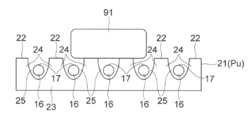
- FIG. 2 is a schematic cross-sectional view showing the relationship between the catcher arranged at the ascending position and the first conveyed object.
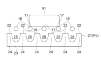
- FIG. 3 is a schematic cross-sectional view showing the relationship between the catcher arranged at the descending position and the first conveyed object.
- FIG. 4 is a plan view showing an example of a catcher (particularly a mounting surface).
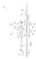
- FIG. 5 is a plan view showing a schematic configuration of an example of the transport device according to the second embodiment.
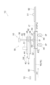
- FIG. 6 is a side view schematically showing an example of the operating state of the transport device of FIG.
- FIG. 7 is a side view schematically showing an example of the operating state of the transport device of FIG.
- FIG. 8 is a side view schematically showing an example of the operating state of the transport device of FIG.
- FIG. 9 is a block diagram showing an example of a control unit of the transport device according to the second
- upward and “downward” are based on the vertical direction, which is the direction of action of gravity, unless otherwise specified, the vertical direction is the downward direction, and the direction opposite to the vertical direction is the direction opposite to the vertical direction. It is upward.
- the height direction is parallel to the vertical direction, and the horizontal direction is a direction perpendicular to the vertical direction.
- upstream and downstream are based on the transport direction of the transport object unless otherwise specified.
- FIG. 1 is a side view showing an outline of an example of the transport device 10 according to the first embodiment.
- FIG. 2 is a schematic cross-sectional view showing the relationship between the catcher 21 arranged at the ascending position Pu and the first conveyed object 91.
- FIG. 3 is a schematic cross-sectional view showing the relationship between the catcher 21 arranged at the descending position Pd and the first conveyed object 91.
- FIGS. 2 and 3 for convenience, only five transport bodies 16 and only six protrusions 24 are shown, but the number of transport bodies 16 and protrusions 24 is not limited. More or less carriers 16 and / or protrusions 24 may be provided.
- the transport device 10 shown in FIG. 1 is a device that transports the first transport object 91 in the transport direction A1.
- the first conveyed object 91 is not limited, and may be a solid, a liquid, or a mixture of a solid and a liquid, and may or may not have fluidity.
- the use of the first transported object 91 is not limited, and the first transported object 91 may be various objects used in foods, daily necessities, industrial products, and other technical fields.
- the transport device 10 includes a conveyor 15, a catcher 21, and a transport object supply unit 30.
- the conveyor 15 has a transport body 16 that moves in a transport direction A1 parallel to the horizontal direction.
- the upper surface of the transport body 16 constitutes the transport surface 17.
- the first transport object 91 supplied from the transport object supply unit 30 via the catcher 21 is placed on the transport surface 17.
- the transport surface 17 forms a flat surface extending parallel to the horizontal direction over at least a part of the range in which the transport surface 17 travels (the entire range in which the first transport object 91 is moved).
- the specific configuration of the carrier 16 is not limited.
- the transport body 16 has a configuration capable of transporting the first transport object 91 while appropriately holding the first transport object 91, and is used for processing by an upstream device and / or a downstream device (not shown in FIG. 1). It has a suitable configuration.
- one or more endless belts can form the carrier 16.
- the cross-sectional size and cross-sectional shape of the belt constituting the carrier 16 are also not limited.
- an endless belt having a cross section in which the size in the horizontal direction (for example, the horizontal direction perpendicular to the transport direction A1) is larger than the size in the vertical direction (for example, the height direction) may be used as the transport body 16.
- the illustrated conveyor 15 has a plurality of string-shaped conveyors 16 (see FIGS. 2 and 3). Each transport body 16 extends in the transport direction A1 and has a substantially circular cross section. These transport bodies 16 are located at equal intervals from each other in the horizontal direction forming a right angle with the transport direction A1.
- the transport surface 17 is composed of a set of outer peripheral surfaces (particularly, an upper side surface facing upward) of a plurality of string-shaped transport bodies 16.
- each string-shaped carrier 16 that is, the cross section perpendicular to the traveling direction (transport direction A1)
- the size in the horizontal direction is equal to or less than the size in the vertical direction (for example, the height direction). It is preferably smaller than the vertical size.
- the shape of the cross section of each carrier 16 is not limited, and each carrier 16 has a polygonal shape, a circular shape (for example, a perfect circular shape or an elliptical shape), or a cross section of another shape. Can have.
- the catcher 21 has a mounting surface 22 on which the first conveyed object 91 supplied from the conveyed object supply unit 30 is placed, and is located between the ascending position Pu (see FIG. 2) and the descending position Pd (see FIG. 3). It is provided so that it can be raised and lowered.
- the specific configuration of the catcher 21 is not limited.
- the illustrated catcher 21 has a main body portion 23 extending in the horizontal direction, and a plurality of protruding portions 24 provided so as to project upward from the main body portion 23. These protrusions 24 are located at equal intervals from each other in the horizontal direction forming a right angle with the transport direction A1. Each protrusion 24 extends in the transport direction A1 and is provided over the entire transport direction A1 of the catcher 21.
- a storage groove 25 extending in the transport direction A1 is formed between the adjacent protrusions 24.
- Each accommodating groove 25 is provided over the entire transport direction A1 of the catcher 21.
- the cross-sectional shape and cross-sectional size of the accommodating groove 25 are not limited.
- each transport body 16 does not hinder the running of each transport body 16 in the transport direction A1 and each transport body 16 does not protrude above the mounting surface 22.
- the carrier 16 is located in the corresponding accommodating groove 25 between the protrusions 24.
- each protruding portion 24 constitutes a mounting surface 22.
- the mounting surface 22 is located above the transport surface 17.
- the mounting surface 22 is located below the conveying surface 17.
- the mounting surface 22 may be located at the same height as the transport surface 17.
- the catcher 21 moves between the ascending position Pu and the descending position Pd, at least a part of the catcher 21 (protruding portion 24 in the illustrated example) passes through the space between the carriers 16 located adjacent to each other. Go up and down.
- the transport object supply unit 30 mounts the first transport object 91 on the mounting surface 22 so that the first transport object 91 is received by the mounting surface 22 above the transport surface 17.
- the relationship between the timing at which the conveyed object supply unit 30 releases the first conveyed object 91 and the timing at which the catcher 21 moves toward the ascending position Pu is not limited.
- the transport object supply unit 30 may discharge the first transport object 91 toward the mounting surface 22 while the catcher 21 is already arranged at the ascending position Pu. In this case, since the first conveyed object 91 lands on the catcher 21 in the stopped state, the force received by the first conveyed object 91 from the catcher 21 is relatively small.
- the conveyed object supply unit 30 may release the first conveyed object 91 toward the mounting surface 22.
- the time required for a series of processes can be shortened.
- FIG. 4 is a plan view showing an example of the catcher 21 (particularly the mounting surface 22).
- the upper end surface (that is, the mounting surface 22) of the protruding portion 24 is indicated by a solid black portion, and the groove portion is indicated by a blank portion.
- the catcher 21 shown in FIG. 4 has a plurality of accommodating groove portions 25 extending in the transport direction A1 (Y direction shown in FIG. 4), and a horizontal direction (particularly, a horizontal direction perpendicular to the transport direction A1) in a direction non-parallel to the transport direction A1. It has a plurality of locking grooves 26 extending in the X direction)) shown in FIG. With respect to the transport direction A1 (Y direction), the mounting surface 22 and the locking groove 26 are alternately and repeatedly arranged on a straight line.
- the first conveyed object 91 mounted on the mounting surface 22 is arranged so as to cover a plurality of locking groove portions 26, and the holding force (that is, frictional force and / or hooking force) is increased by these locking groove portions 26. ing.
- the mounting surface 22 No horizontal force acts on the first transport object 91 above.
- the first transport object 91 moves toward the catcher 21 in a non-parallel direction in the vertical direction or when the mounting surface 22 is tilted from the horizontal direction, the first transport object 91 on the mounting surface 22 A horizontal force acts on.
- the first conveyed object 91 is accurately held on the mounting surface 22 whose holding force is increased by the accommodating groove 25 and the locking groove 26, the first on the mounting surface 22. It is possible to effectively prevent the conveyed object 91 from slipping or rolling.
- the transport object supply unit 30 discharges the first transport object 91 toward the catcher 21, but the first transport object 91 may be mounted on the mounting surface 22 by another method.
- the first conveyor object 91 may be conveyed non-parallel to the vertical direction by a conveyor (not shown), and the first conveyor object 91 may be moved from the conveyor to the mounting surface 22 of the catcher 21.
- the mounting surface 22 has the accommodating groove portion 25 and the locking groove portion 26, it is possible to effectively prevent the first conveyed object 91 from slipping or rolling on the mounting surface 22.
- Each locking groove 26 may be shallower or deeper than the accommodating groove 25.
- the width of each locking groove 26 in the transport direction A1 (Y direction) is not limited, and each locking groove 26 may have a fine width of 1 mm or less.
- each locking groove 26 is not limited to the configuration shown in FIG.
- the locking groove portions 26 may extend in the same direction as each other, or the catcher 21 may have two or more locking groove portions 26 extending in different directions from each other.
- the extending direction of the locking groove portion 26 is not limited, and is non-parallel to each of the transport direction A1 (Y direction) and the horizontal direction (X direction shown in FIG. 4) perpendicular to the transport direction A1, and these directions.
- Each locking groove 26 may extend in an oblique direction (see the arrow indicated by "Q" in FIG. 4) with respect to each of (X direction and Y direction).
- the mounting surface 22 (upper end surface of the protruding portion 24) may be arranged in a staggered manner, and the locking groove portions 26 arranged in a straight line in the horizontal direction (X direction) forming a right angle with the transport direction A1.
- the accommodating groove 25 and the mounting surface 22 may be repeatedly provided.
- the catcher 21 does not have to have the locking groove portion 26.
- the transport object supply unit 30 is the first even if the locking groove 26 is not provided in the catcher 21.
- the conveyed object 91 can be stably placed on the catcher 21.
- the transport method performed by the transport device 10 may have a role as a part of the food production method performed by the food production system including the transport device 10.
- the transport body 16 basically continues to move in the transport direction A1 at a constant speed without intermittently stopping during the following processing.
- the transport surface 17 continuously moves from the upstream side of the transport object supply unit 30 to the downstream side of the transport object supply unit 30 through below the transport object supply unit 30.
- the transport object supply unit 30 mounts the first transport object 91 on the mounting surface 22 so that the first transport object 91 is received by the mounting surface 22 above the transport surface 17.
- the catcher 21 is moved from the ascending position Pu toward the descending position Pd.
- the first transported object 91 is received by the transport surface 17, and is delivered from the mounting surface 22 to the transport surface 17.
- the first conveyed object 91 is conveyed downstream by the conveyed body 16 in a state of being mounted on the conveyed surface 17.
- the raising and lowering operation of the catcher 21 and the release operation of the first conveyed object 91 from the conveyed object supply unit 30 are typically performed under the control of the control unit (not shown). However, if the ascending / descending operation of the catcher 21 and the release operation of the first conveyed object 91 from the conveyed object supply unit 30 can be linked to each other as described above, the catcher 21 and / or the conveyed object supply unit 30 Does not have to be controlled by the control unit.
- a plurality of first conveyed objects 91 are continuously gentle to the conveyed body 16 via the catcher 21. It is loaded and sent downstream.
- the first conveyed object 91 released from the conveyed object supply unit 30 is received by the catcher 21 that is not moving in the conveying direction A1, it is placed on the catcher 21 without being affected by the inertia in the conveying direction A1. Be done. Therefore, the first conveyed object 91 can be stably and accurately placed on the desired portion of the catcher 21.
- the first transport object 91 Is delivered to the transport surface 17. In this way, since the first transport object 91 is supported by the mounting surface 22 at least until just before it is delivered to the transport surface 17, the first transport object 91 can be stably and accurately mounted on the transport body 16. Can be done.
- the first transfer object 91 is stably and accurately placed on the transfer body 16 while the first transfer object 91 is conveyed at high speed by the transfer body 16. Can be done.
- the first transport object 91 is directly mounted on the transport body 16 without using the catcher 21, there is a concern that the first transport object 91 may tip over on the transport body 16, the arrangement position may be displaced, or the first transport object 91 may be damaged. is there. According to the transport device 10 of the present embodiment, such a problem can be effectively avoided.
- FIG. 5 is a plan view showing a schematic configuration of an example of the transport device 10 according to the second embodiment.
- 6 to 8 are side views schematically showing an example of an operating state of the transport device 10 of FIG.
- FIG. 9 is a block diagram showing an example of a control unit of the transport device 10 according to the second embodiment.
- the introduction section 51 and the release section 55 are not shown.
- the holding case 45 including the holding hole 47
- the top plate holding portion 46 including the introduction hole 44 and the top plate hole 48
- the first transport object 91 (that is, “installation work”) is placed on the second transport object 92 (that is, “reception work”) that is sent from the upstream by the conveyor 15.
- a set of 1 transport object 91 and a second transport object 92 is sent downstream.
- the first conveyed object 91 and the second conveyed object 92 are not limited.
- the second transport object 92 has a sheet shape, and the first transport object 91 can be large enough to be wrapped by the second transport object 92.
- at least one of the first transport object 91 and the second transport object 92 may be plastic, and a heated and fluid plastic may be used as the first transport object 91.
- at least one of the first conveyed object 91 and the second conveyed object 92 may be foodstuffs.
- the first transport object 91 is a paste-like food material
- the second transport object 92 is a bendable flexible sheet-like food material
- the transport device 10 is configured as a part of a food manufacturing system.
- the transport body 16 moves in the transport direction A1 with the second transport object 92 mounted on the transport surface 17.
- the catcher 21 moves from the descending position Pd to the ascending position Pu so that the second conveyed object 92 is placed on the mounting surface 22 of the catcher 21 arranged at the ascending position Pu.
- the transport object supply unit 30 places the first transport object 91 on the mounting surface 22 so that the first transport object 91 lands on the second transport object 92 mounted on the mounting surface 22.
- the catcher 21 of the present embodiment includes a plurality of accommodating groove portions 25 extending in the transport direction A1 and a plurality of locking groove portions 26 extending in a direction non-parallel to the transport direction A1. Has (see FIG. 4).
- the accommodating groove 25 and the locking groove 26 (particularly the locking groove 26) increase the anti-slip effect of the second transport object 92 on the mounting surface 22, and the catcher 21 accurately holds the second transport object 92. Can be retained.
- the conveyed object supply unit 30 has a mold 41 and a discharge unit 55.
- the mold 41 is filled with the first conveyed object 91 and has a forming space 42 for forming the first conveyed object 91.
- the discharge unit 55 applies a force to the first transport object 91 so as to discharge the first transport object 91 arranged in the molding space 42 toward the mounting surface 22 of the catcher 21.
- the illustrated mold 41 extends horizontally between the holding case 45 and the top plate holding portion 46, and extends horizontally along the holding case 45 and the top plate holding portion 46 (“slides” shown in FIGS. 7 and 8). It is held so as to be slidable in the direction A4 ").
- a mold moving body 43 is attached to the mold 41, and the mold moving body 43 is connected to a mold driving unit 49 (see FIG. 9) such as a motor.
- the mold 41 reciprocates in the slide direction A4 while being guided by the holding case 45 and the top plate holding portion 46 according to the power transmitted from the mold driving unit 49 (see FIG. 9) to the mold moving body 43.
- the mold 41 which moves together with the mold moving body 43 in this way, has a filling position (see FIGS. 6 and 8) for filling the molding space 42 with the first conveyed object 91, and the molding space 42 to the first conveyed object 91. Can be placed at the release position (see FIG. 7) for releasing.
- a top plate holding portion 46 is provided above the holding case 45, and the holding case 45 and the top plate holding portion 46 are fixedly supported by a support frame (not shown).
- An introduction portion 51 is fixed on the top plate holding portion 46.
- the introduction unit 51 has an internal space (not shown) through which the first conveyed object 91 can pass.
- a supply device (not shown) is connected to the introduction unit 51, and the paste-like first conveyed object 91 is supplied from the supply device to the internal space of the introduction unit 51.
- the top plate holding portion 46 has an introduction hole 44 connected to the internal space of the introduction portion 51.
- the molding space 42 communicates with the internal space of the introduction portion 51 via the introduction hole 44.
- the top plate holding portion 46 further has a top plate hole 48.
- the top plate hole 48 is located so as to overlap the punched portion 59 of the conveyed object supply portion 30 in the height direction, and has a shape and size that allows the punched portion 59 to pass in the height direction.
- the molding space 42 is located below the top plate hole 48 so as to overlap the punched portion 59 and the top plate hole 48 in the height direction, and the punched portion 59 is at a height. It has a shape and size that allows it to pass in the direction.
- the illustrated release unit 55 has a release drive unit 56 and a punching unit 59 fixed to the release drive unit 56 and extending downward.
- the punching portion 59 is driven by the discharge driving portion 56 to adjust the amount of protrusion downward from the discharge driving portion 56, and the position of the lower tip of the punching portion 59 changes in the height direction.
- the lower tip of the punched portion 59 is a retracted position (see FIGS. 6 and 8) which is a position above the mold 41 (a position above the top plate holding portion 46 in the illustrated example). It can be arranged at a punching position (see FIG. 7) which is a position below the mold 41 (a position below the holding case 45 in the illustrated example).
- the discharge unit 55 shown in the figure is shown in a simplified manner, and the discharge drive unit 56 and the punching unit 59 have an arbitrary configuration.
- the discharge unit 55 can be configured by using an air cylinder or a ball screw mechanism.
- the catcher 21 is located directly below the punched portion 59, the top plate hole 48, and the holding hole 47, and directly below the molding space 42 of the mold 41 arranged at the discharge position.
- the catcher 21 is mounted on a plurality of drive cams 36 (in the illustrated example, two drive cams 36 provided side by side in the transport direction A1).
- Each drive cam 36 is driven by a catcher drive unit 35 (see FIG. 9) such as a motor, and is rotated about a corresponding cam shaft 37.
- each drive cam 36 has an oval (for example, elliptical) outer shape, and the height direction position of the outermost portion of each drive cam 36 (that is, the height direction position of the portion in contact with the catcher 21) is , It changes according to the rotation state of each drive cam 36.
- These drive cams 36 are synchronously driven so as to have the same posture with each other, and are in a rotational state for arranging the catcher 21 at the descending position Pd (see FIGS. 6 and 8) and the catcher 21 at the ascending position Pu. It can be placed in a rotating state (see FIG. 7) for placement in.
- a mechanism for synchronously driving a plurality of drive cams 36 is already known, and detailed description thereof will be omitted.
- a trigger sensor 33 is provided on the upstream side of the transport object supply unit 30 and above the transport body 16.
- the trigger sensor 33 is a sensor that detects the passage of the second conveyed object 92 directly under the trigger sensor 33, and can be typically configured by an optical sensor. As shown in FIG. 9, the trigger sensor 33 is connected to the control unit 65, and the detection result of the trigger sensor 33 is sent to the control unit 65.
- the control unit 65 controls the release drive unit 56, the catcher drive unit 35, and the mold drive unit 49 based on the detection result of the trigger sensor 33. That is, the release drive unit 56, the catcher drive unit 35, and the mold drive unit 49 are controlled according to the transfer position of the second conveyed object 92, and the punching unit 59, the catcher 21, and the mold 41 are moved in association with each other. ..
- the transport body 16 basically continues to move in the transport direction A1 at a constant speed without intermittently stopping during the following processing.
- a plurality of second transport objects 92 are placed on the transport body 16 of the conveyor 15 in a state of being spaced apart from each other in the transport direction A1 (see FIG. 6).
- the work of mounting the plurality of second transport objects 92 on the transport body 16 may be performed mechanically or manually.
- the second transported object 92 is transported in the transport direction A1 by the transport body 16, is detected by the trigger sensor 33 on the upstream side of the transport object supply unit 30, and is above the catcher 21 (specifically, directly below the punched portion 59). It is lifted from the transport surface 17 by the catcher 21 at the timing of reaching the desired position (see FIG. 7).
- the control unit 65 calculates the time for the second conveyed object 92 to reach a desired position above the catcher 21 (that is, directly below the punched portion 59) based on the detection result of the trigger sensor 33 and the traveling speed of the conveyed body 16.
- the control unit 65 controls the catcher drive unit 35 based on the calculation result, and eventually controls the rotational state of each drive cam 36.
- the catcher 21 is arranged in the descending position Pd and the mounting surface 22 is located below the conveying surface 17 until the second conveyed object 92 reaches a desired position above the catcher 21 (that is, directly below the punching portion 59). To do.
- the catcher 21 is moved upward by the drive cam 36.
- the catcher 21 is arranged at the ascending position Pu, the mounting surface 22 is arranged above the transport surface 17, and the second transport object 92 is mounted on the mounting surface 22 and continues in the transport direction A1. It is separated from the moving transport surface 17. In this way, the second transport object 92 is fixedly positioned with respect to the transport direction A1 by the catcher 21 without stopping the transport body 16.
- the mold 41 is arranged at the filling position before the second conveyed object 92 reaches above the catcher 21 (that is, directly below the punched portion 59), and the introduction portion 51 and the introduction hole 44 are provided in the molding space 42.
- the first conveyed object 91 is filled through. After the molding space 42 is filled with the first conveyed object 91, the mold 41 is moved from the filling position to the discharging position. As a result, the first conveyed object 91 is molded into a desired shape according to the shape of the molding space 42.
- the punching portion 59 is lowered so as to pass through the top plate hole 48, the forming space 42, and the holding hole 47 according to the timing when the second conveyed object 92 is lifted by the catcher 21.
- the first conveyed object 91 in the molding space 42 of the mold 41 arranged at the discharge position is pushed downward by the punching portion 59, and the first conveyed object 91 is placed on the mounting surface 22 of the catcher 21. It is placed on the second conveyed object 92.
- the drive cam 36 is rotated under the control of the control unit 65, and the catcher 21 is arranged at the descending position Pd (see FIG. 8).
- the first conveyed object 91 and the second conveyed object 92 on the mounting surface 22 are placed on the transport surface 17 of the transport body 16 and separated from the mounting surface 22.
- the first transport object 91 and the second transport object 92 mounted on the transport surface 17 are transported downstream by the transport body 16.
- the punching portion 59 punches the first conveyed object 91 from the molding space 42, and then moves from the punching position to the retracted position. After that, the mold 41 moves from the discharge position to the filling position. Then, the molding space 42 of the mold 41 arranged at the filling position is filled with the new first conveyed object 91 sent through the internal space of the introduction portion 51 and the introduction hole 44.
- the set of the first conveyed object 91 and the second conveyed object 92 can be continuously sent to the downstream side of the conveyed object supply unit 30. it can.
- the first conveyed object 91 can be conveyed downstream while being mounted on the second conveyed object 92.
- the process of mounting the first transport object 91 on the second transport object 92 is performed in a state where the second transport object 92 is stopped in the transport direction A1, the first transport object 91 is not affected by the inertia in the transport direction A1. 2
- the first conveyed object 91 can be accurately arranged at a desired position on the conveyed object 92.
- the transport device 10 of the present embodiment it is possible to effectively avoid such defects in the subsequent processing and deterioration of the quality of the final product.
- the first conveyed object 91 is punched out from the molding space 42 as shown in the drawing, it is inevitable that an impact is applied to the first conveyed object 91 at the time of landing.
- the impact force applied to the first transport object 91 is applied. Can be reduced.
- the mounting surface 22 of the catcher 21 rises as in the present embodiment, and the configuration for shortening the falling distance of the first conveyed object 91 is the first. 1 It is preferable from the viewpoint of reducing the impact force acting on the conveyed object 91.
- the catcher 21 does not move in the horizontal direction. No or little horizontal force acts on the first conveyed object 91. Therefore, there is no or almost no horizontal relative misalignment between the first conveyed object 91 and the second conveyed object 92. Further, even if it is difficult to peel off the first conveyed object 91 from the punched portion 59 due to the strong adhesiveness of the first conveyed object 91, the first conveyed object 91 is pressed against the second conveyed object 92 by the punched portion 59. The first conveyed object 91 can be effectively peeled off from the punched portion 59 and placed on the second conveyed object 92.
- the height of the lower tip of the punching portion 59 can be easily changed by changing the driving amount of the punching portion 59 by the discharge driving portion 56 (that is, the amount of protrusion downward from the discharge driving portion 56).
- the direction position can be changed.
- the shape of the catcher 21 is not limited.
- the catcher 21 may be composed of a set of a plurality of protrusions provided separately from each other. Two or more of such a plurality of protrusions may be arranged apart from each other in the transport direction A1 or may be arranged apart from each other in the horizontal direction perpendicular to the transport direction A1. Good. However, it is easier to handle the catcher 21 when the number of members constituting the catcher 21 is small, and by forming the entire catcher 21 with an integral member, it is advantageous in terms of handleability and manufacturing cost of the catcher 21. There are many things.
- the ability of the catcher 21 to hold the first transport object 91 and / or the second transport object 92 may be improved by other means together with the locking groove 26 or instead of the locking groove 26.
- the mounting surface 22 may be formed of a rough surface to improve the frictional force of the mounting surface 22.
- the holding ability of the catcher 21 may be improved by subjecting the mounting surface 22 to an arbitrary treatment (for example, physical treatment and / or chemical treatment) for improving the frictional force.
- the punching portion 59 When the first conveyed object 91 is discharged from the molding space 42, the punching portion 59 does not have to penetrate the molding space 42, and the lower tip of the punching portion 59 entering the molding space 42 may be stopped in the molding space 42. Good. Further, the method and means for discharging the first conveyed object 91 from the molding space 42 are not limited.
- the conveyed object supply unit 30 may discharge the first conveyed object 91 from the forming space 42 toward the catcher 21 by blowing compressed air onto the forming space 42.
- the composition, shape, size, and other characteristics of the carrier 16 are not limited.
- the transport body 16 is a member having a large contact area with the first transport object 91 or the second transport object 92 (for example, a wide member). It is preferable that it is composed of a belt), and it is preferable that the entire lower surface of the first conveyed object 91 is supported by the conveyed body 16.
- the conveyed body 16 is a member having a small contact area with the first conveyed object 91 or the second conveyed object 92 (
- it is preferably composed of a string-shaped member). Therefore, when the first transport object 91 or the second transport object 92 has a strong adhesiveness (for example, when the first transport object 91 or the second transport object 92 has a large amount of water retained), the string-shaped member is preferably used as the transport body 16. Can be used.
- the conveyed object supply unit 30 and / or the conveyor 15 may be provided so as to be movable in the height direction.
- the distance between the transport object supply unit 30 and the conveyor 15 (particularly, the transport body 16 (specifically, the transport surface 17)) in the height direction can be changed.
- the conveyor 15 is often not easily mobile. In such a case, from the viewpoint of reducing the work load, it is preferable to change the distance between the conveyed object supply unit 30 and the conveyor 15 by changing the position of the conveyed object supply unit 30 in the height direction.
- the carrier 16 and the catcher 21 may be provided at positions where they overlap each other in the height direction, but the carrier 16 and the catcher 21 may be provided at positions where they do not overlap each other in the height direction.
- both ends of the first transport object 91 or the second transport object 92 (that is, both ends in the horizontal direction perpendicular to the transport direction A1) have relatively high rigidity of the first transport object 91 or the second transport object 92. ) May be mounted on the transport body 16 and transported.
- the transport bodies 16 that are separate from each other may be installed at positions corresponding to both ends of the first transport object 91 or the second transport object 92, and the catcher 21 may be installed between the transport bodies 16.
- the catcher 21 does not overlap with the transport body 16 in the height direction, and can be provided so as to be in contact with the central portion of the first transport object 91 or the second transport object 92.
- the composition, shape, size, and other characteristics of the first transport object 91 and the second transport object 92 are not limited.
- the first transport object 91 and the second transport object 92 may be configured by the following elements.
- the first conveyed object 91 may contain an amorphous pasty food material having fluidity (for example, a viscous food material), may be composed of a single type of food material, or may contain a plurality of types of foodstuffs. You may. For example, meat, seafood, vegetables, mushrooms, grains, fruits, seaweeds, beans, chocolates, cookies, crackers, puffs, candy, gummies and other solid ingredients, as well as eggs, milk, water, oils. , Seasonings, spices, sugars, grain flour, starches, gelling agents, thickeners and other liquid foods, viscous foods (eg dripping, sauces, creams, etc.), foaming foods (eg whipped cream, etc.) , Can be included in the first transport object 91.
- amorphous pasty food material having fluidity for example, a viscous food material
- You may. For example, meat, seafood, vegetables, mushrooms, grains, fruits, seaweeds, beans, chocolates, cookies, crackers, puffs, candy,
- the first conveyed object 91 may include a plurality of raw materials in different states (for example, a solid raw material and a liquid raw material).
- the second conveyed object 92 may be composed of, for example, a flexible sheet-like member that can be easily bent. Therefore, an edible skin (for example, a skin made of rice flour, wheat flour, or an egg) or a packaging member (for example, wrapping paper) for wrapping the above-mentioned edible material (first transport object 91) is used as the second transport object 92. You may. Further, edible and non-edible members used for purposes other than wrapping the first conveyed object 91 may be used as the second conveyed object 92.
- the present disclosure is not limited to the above-described embodiments and modifications. For example, various modifications may be added to each element of the above-described embodiment and modification. Also included in the embodiments of the present disclosure are embodiments that include components and / or methods other than the components and / or methods described above. Also included in the embodiments of the present disclosure are embodiments that do not include some of the components and / or methods described above. Also disclosed are embodiments that include some components and / or methods included in certain embodiments of the present disclosure and some components and / or methods included in other embodiments of the present disclosure. Included in the embodiments.
- Conveying device 15 Conveyor 16 Conveying body 17 Conveying surface 21 Catcher 22 Mounting surface 23 Main body 24 Protruding part 25 Accommodating groove 26 Locking groove 30 Conveyed object supply 33 Trigger sensor 35 Catcher drive 36 Drive cam 37 Camshaft 41 Mold 42 Molding space 43 Mold moving body 44 Introduction hole 45 Holding case 46 Top plate holding part 47 Holding hole 48 Top plate hole 49 Mold drive part 51 Introduction part 55 Discharge part 56 Discharge drive part 59 Punching part 65 Control part 91 First object to be conveyed 92 Second transport object A1 Transport direction A2 Movement direction A3 Lifting direction A4 Sliding direction Pu Lifting position Pd Lowering position
Landscapes
- Engineering & Computer Science (AREA)
- Life Sciences & Earth Sciences (AREA)
- Food Science & Technology (AREA)
- Mechanical Engineering (AREA)
- Chemical & Material Sciences (AREA)
- Polymers & Plastics (AREA)
- Attitude Control For Articles On Conveyors (AREA)
- Feeding Of Articles To Conveyors (AREA)
- Formation And Processing Of Food Products (AREA)
- Structure Of Belt Conveyors (AREA)
Priority Applications (3)
| Application Number | Priority Date | Filing Date | Title |
|---|---|---|---|
| CN202080064591.2A CN114401911B (zh) | 2019-10-03 | 2020-09-28 | 输送装置、输送方法及食品制造方法 |
| JP2021551240A JP7541990B2 (ja) | 2019-10-03 | 2020-09-28 | 搬送装置、搬送方法及び食品製造方法 |
| US17/762,300 US12091261B2 (en) | 2019-10-03 | 2020-09-28 | Conveyance apparatus, conveyance method and food production method |
Applications Claiming Priority (2)
| Application Number | Priority Date | Filing Date | Title |
|---|---|---|---|
| JP2019-183060 | 2019-10-03 | ||
| JP2019183060 | 2019-10-03 |
Publications (1)
| Publication Number | Publication Date |
|---|---|
| WO2021065786A1 true WO2021065786A1 (ja) | 2021-04-08 |
Family
ID=75336559
Family Applications (1)
| Application Number | Title | Priority Date | Filing Date |
|---|---|---|---|
| PCT/JP2020/036598 Ceased WO2021065786A1 (ja) | 2019-10-03 | 2020-09-28 | 搬送装置、搬送方法及び食品製造方法 |
Country Status (4)
| Country | Link |
|---|---|
| US (1) | US12091261B2 (https=) |
| JP (1) | JP7541990B2 (https=) |
| CN (1) | CN114401911B (https=) |
| WO (1) | WO2021065786A1 (https=) |
Families Citing this family (1)
| Publication number | Priority date | Publication date | Assignee | Title |
|---|---|---|---|---|
| WO2024242867A1 (en) * | 2023-05-22 | 2024-11-28 | Laitram, L.L.C. | System for selectively stopping product flow in a conveyor |
Citations (4)
| Publication number | Priority date | Publication date | Assignee | Title |
|---|---|---|---|---|
| JPS60169148A (ja) * | 1984-02-13 | 1985-09-02 | Dainippon Screen Mfg Co Ltd | 基板の搬送方法及びその装置 |
| JPH0222927U (https=) * | 1988-07-29 | 1990-02-15 | ||
| JPH0439214A (ja) * | 1990-05-30 | 1992-02-10 | Food Supply Jiyasuko:Kk | スライスされた肉の搬送および収納装置 |
| JP3032110U (ja) * | 1996-06-07 | 1996-12-17 | 功 菊地 | 菓子成形機 |
Family Cites Families (8)
| Publication number | Priority date | Publication date | Assignee | Title |
|---|---|---|---|---|
| JP3805207B2 (ja) * | 2001-03-19 | 2006-08-02 | アイダエンジニアリング株式会社 | 材料搬送装置 |
| JP4276800B2 (ja) * | 2001-08-17 | 2009-06-10 | 株式会社コバード | 食品の包み込み成形方法とその装置 |
| JP2004129524A (ja) | 2002-10-08 | 2004-04-30 | Rheon Autom Mach Co Ltd | 食品生地の包あん方法およびその装置 |
| US8847122B2 (en) * | 2009-06-08 | 2014-09-30 | Macronix International Co., Ltd. | Method and apparatus for transferring substrate |
| CN104444297B (zh) | 2014-11-21 | 2016-09-14 | 椿中岛机械(重庆)有限公司 | 钢球自动缓冲接料装置 |
| CN108569510B (zh) * | 2017-11-24 | 2020-03-27 | 中国国际海运集装箱(集团)股份有限公司 | 行李筐的输送设备和行李安检系统 |
| CN108589510B (zh) | 2018-05-15 | 2020-08-04 | 嘉兴晟源工业设计有限公司 | 一种防富营养化式桥梁 |
| CN208932471U (zh) | 2018-09-14 | 2019-06-04 | 深圳长城开发科技股份有限公司 | 磁性载具分离供料机构 |
-
2020
- 2020-09-28 JP JP2021551240A patent/JP7541990B2/ja active Active
- 2020-09-28 US US17/762,300 patent/US12091261B2/en active Active
- 2020-09-28 CN CN202080064591.2A patent/CN114401911B/zh active Active
- 2020-09-28 WO PCT/JP2020/036598 patent/WO2021065786A1/ja not_active Ceased
Patent Citations (4)
| Publication number | Priority date | Publication date | Assignee | Title |
|---|---|---|---|---|
| JPS60169148A (ja) * | 1984-02-13 | 1985-09-02 | Dainippon Screen Mfg Co Ltd | 基板の搬送方法及びその装置 |
| JPH0222927U (https=) * | 1988-07-29 | 1990-02-15 | ||
| JPH0439214A (ja) * | 1990-05-30 | 1992-02-10 | Food Supply Jiyasuko:Kk | スライスされた肉の搬送および収納装置 |
| JP3032110U (ja) * | 1996-06-07 | 1996-12-17 | 功 菊地 | 菓子成形機 |
Also Published As
| Publication number | Publication date |
|---|---|
| CN114401911B (zh) | 2023-10-03 |
| US20220411198A1 (en) | 2022-12-29 |
| JPWO2021065786A1 (https=) | 2021-04-08 |
| JP7541990B2 (ja) | 2024-08-29 |
| CN114401911A (zh) | 2022-04-26 |
| US12091261B2 (en) | 2024-09-17 |
Similar Documents
| Publication | Publication Date | Title |
|---|---|---|
| KR101196110B1 (ko) | 샌드위치 구이 제품 연속 생산 방법 및 그 장치 | |
| JP3364505B2 (ja) | フリップ−スライド装置 | |
| CN1234281C (zh) | 单层排列的快餐薄脆片传输系统与方法 | |
| US5236502A (en) | Apparatus for coating foodstuffs | |
| CN109803908A (zh) | 处理休闲食品片 | |
| WO1995003988A1 (en) | Handling sheet material | |
| US3427910A (en) | Pastry table product separating conveyor | |
| US20100285187A1 (en) | Apparatus and methods for cutting individual pieces from a food extrudate | |
| EP3629746B1 (en) | A food processing system and a food processing method | |
| JPS62208306A (ja) | 包装機械 | |
| WO2021065786A1 (ja) | 搬送装置、搬送方法及び食品製造方法 | |
| CN1823616A (zh) | 通过受控帘倾泻来成形和烹制的方法和装置 | |
| US20230380473A1 (en) | Crumble pieces comprising plant-sourced lipid and inulin | |
| US6435079B2 (en) | Machine for preparing food products | |
| JP3238284U (ja) | 食品成形装置 | |
| US20230380474A1 (en) | Automated Burrito Maker | |
| US20250236476A1 (en) | Apparatus and method for stacking food portions, in particular patties | |
| US2696234A (en) | Apparatus for slicing edible products | |
| JP2004024008A (ja) | 食品成形処理装置及び食品成形方法 | |
| JP3507064B1 (ja) | パンの製造方法及び装置 | |
| TWM619041U (zh) | 食品成形裝置 | |
| PL203854B1 (pl) | Urządzenie do wytwarzania ciastek, z elektronicznym układem sterującym | |
| JPH0620882B2 (ja) | トレー充填装置 |
Legal Events
| Date | Code | Title | Description |
|---|---|---|---|
| 121 | Ep: the epo has been informed by wipo that ep was designated in this application |
Ref document number: 20871514 Country of ref document: EP Kind code of ref document: A1 |
|
| ENP | Entry into the national phase |
Ref document number: 2021551240 Country of ref document: JP Kind code of ref document: A |
|
| NENP | Non-entry into the national phase |
Ref country code: DE |
|
| 122 | Ep: pct application non-entry in european phase |
Ref document number: 20871514 Country of ref document: EP Kind code of ref document: A1 |