WO2021065693A1 - ヘッド装置、液体吐出装置及びヘッドメンテナンス方法 - Google Patents
ヘッド装置、液体吐出装置及びヘッドメンテナンス方法 Download PDFInfo
- Publication number
- WO2021065693A1 WO2021065693A1 PCT/JP2020/036171 JP2020036171W WO2021065693A1 WO 2021065693 A1 WO2021065693 A1 WO 2021065693A1 JP 2020036171 W JP2020036171 W JP 2020036171W WO 2021065693 A1 WO2021065693 A1 WO 2021065693A1
- Authority
- WO
- WIPO (PCT)
- Prior art keywords
- head
- wiping
- nozzle
- control unit
- liquid
- Prior art date
- Legal status (The legal status is an assumption and is not a legal conclusion. Google has not performed a legal analysis and makes no representation as to the accuracy of the status listed.)
- Ceased
Links
Images






Classifications
-
- B—PERFORMING OPERATIONS; TRANSPORTING
- B41—PRINTING; LINING MACHINES; TYPEWRITERS; STAMPS
- B41J—TYPEWRITERS; SELECTIVE PRINTING MECHANISMS, i.e. MECHANISMS PRINTING OTHERWISE THAN FROM A FORME; CORRECTION OF TYPOGRAPHICAL ERRORS
- B41J2/00—Typewriters or selective printing mechanisms characterised by the printing or marking process for which they are designed
- B41J2/005—Typewriters or selective printing mechanisms characterised by the printing or marking process for which they are designed characterised by bringing liquid or particles selectively into contact with a printing material
- B41J2/01—Ink jet
- B41J2/135—Nozzles
- B41J2/165—Prevention or detection of nozzle clogging, e.g. cleaning, capping or moistening for nozzles
- B41J2/16517—Cleaning of print head nozzles
- B41J2/16535—Cleaning of print head nozzles using wiping constructions
-
- B—PERFORMING OPERATIONS; TRANSPORTING
- B41—PRINTING; LINING MACHINES; TYPEWRITERS; STAMPS
- B41J—TYPEWRITERS; SELECTIVE PRINTING MECHANISMS, i.e. MECHANISMS PRINTING OTHERWISE THAN FROM A FORME; CORRECTION OF TYPOGRAPHICAL ERRORS
- B41J2/00—Typewriters or selective printing mechanisms characterised by the printing or marking process for which they are designed
- B41J2/005—Typewriters or selective printing mechanisms characterised by the printing or marking process for which they are designed characterised by bringing liquid or particles selectively into contact with a printing material
- B41J2/01—Ink jet
- B41J2/015—Ink jet characterised by the jet generation process
- B41J2/04—Ink jet characterised by the jet generation process generating single droplets or particles on demand
- B41J2/045—Ink jet characterised by the jet generation process generating single droplets or particles on demand by pressure, e.g. electromechanical transducers
- B41J2/04501—Control methods or devices therefor, e.g. driver circuits, control circuits
- B41J2/04596—Non-ejecting pulses
-
- B—PERFORMING OPERATIONS; TRANSPORTING
- B41—PRINTING; LINING MACHINES; TYPEWRITERS; STAMPS
- B41J—TYPEWRITERS; SELECTIVE PRINTING MECHANISMS, i.e. MECHANISMS PRINTING OTHERWISE THAN FROM A FORME; CORRECTION OF TYPOGRAPHICAL ERRORS
- B41J2/00—Typewriters or selective printing mechanisms characterised by the printing or marking process for which they are designed
- B41J2/005—Typewriters or selective printing mechanisms characterised by the printing or marking process for which they are designed characterised by bringing liquid or particles selectively into contact with a printing material
- B41J2/01—Ink jet
- B41J2/135—Nozzles
- B41J2/165—Prevention or detection of nozzle clogging, e.g. cleaning, capping or moistening for nozzles
- B41J2/16517—Cleaning of print head nozzles
- B41J2/16535—Cleaning of print head nozzles using wiping constructions
- B41J2002/1655—Cleaning of print head nozzles using wiping constructions with wiping surface parallel with nozzle plate and mounted on reels, e.g. cleaning ribbon cassettes
-
- B—PERFORMING OPERATIONS; TRANSPORTING
- B41—PRINTING; LINING MACHINES; TYPEWRITERS; STAMPS
- B41J—TYPEWRITERS; SELECTIVE PRINTING MECHANISMS, i.e. MECHANISMS PRINTING OTHERWISE THAN FROM A FORME; CORRECTION OF TYPOGRAPHICAL ERRORS
- B41J2/00—Typewriters or selective printing mechanisms characterised by the printing or marking process for which they are designed
- B41J2/005—Typewriters or selective printing mechanisms characterised by the printing or marking process for which they are designed characterised by bringing liquid or particles selectively into contact with a printing material
- B41J2/01—Ink jet
- B41J2/135—Nozzles
- B41J2/165—Prevention or detection of nozzle clogging, e.g. cleaning, capping or moistening for nozzles
- B41J2/16517—Cleaning of print head nozzles
- B41J2002/1657—Cleaning of only nozzles or print head parts being selected
Definitions
- the present invention relates to a head device, a liquid discharge device, and a head maintenance method.
- An inkjet printing device equipped with an inkjet head is known.
- the inkjet printing apparatus drives the meniscus to vibrate to the extent that the ink is not ejected from the nozzles to suppress deterioration of the ink due to drying of the ink in the nozzles.
- Such driving is called tickle and meniscus shaking and the like.
- the inkjet printing apparatus wipes the nozzle surface of the inkjet head to remove foreign substances such as ink mist adhering to the nozzle surface, and suppresses deterioration of ejection performance due to the adhesion of foreign substances to the nozzle surface. ..
- a wiping member such as a web sheet to which a non-woven fabric or the like is applied and a blade to which rubber or the like is applied is applied.
- the amount of ink drawn from the nozzle to the wiping member can be larger than when the tickle is not applied.
- an inkjet head to which an ink having a component that easily scrapes the liquid-repellent film formed on the nozzle surface is applied, deterioration of the liquid-repellent film is promoted due to the wiping.
- Patent Document 1 describes an inkjet printing apparatus provided with a wiper that wipes the nozzle surface.
- the device described in the same document drives a nozzle that the wiper does not contact when wiping the nozzle surface with the wiper, and reduces the pressure in the pressure chamber communicating with the nozzle that the wiper contacts.
- the meniscus of the nozzle with which the wiper comes into contact is pulled into the back side of the nozzle, and ink leakage due to the destruction of the meniscus is suppressed.
- Patent Document 2 describes an inkjet printing apparatus provided with a wiper that wipes the nozzle surface.
- the device described in the same document applies pulsation to the extent that it does not eject to ink to perform wiping, and reduces wiping defects such as unwiped residue.
- Patent Document 3 describes an inkjet printing apparatus including an inkjet head maintenance apparatus.
- the negative pressure during maintenance of the inkjet head is set in the range of minus 0.8 kilopascals to minus 0.1 kilopascals.
- ink is ejected from a nozzle that the wiper does not contact, and the ink ejected from the nozzle adheres to the wiper.
- ink is attached to the wiper during wiping.
- Patent Document 3 causes ink to leak from the nozzle during wiping.
- the ink leaked from the nozzle adheres to the wiper.
- the particles contained in the ink scrape the liquid repellent film on the nozzle surface, and the liquid repellent film may be worn.
- the present invention has been made in view of such circumstances, and provides a head device, a liquid discharge device, and a head maintenance method capable of suppressing wear of the liquid repellent film on the nozzle surface due to a wiping process on the nozzle surface. With the goal.
- the head device includes an inkjet head in which a liquid-repellent film is formed on the nozzle surface and a head control unit that controls the inkjet head, and the head control unit is subjected to a nozzle surface wiping process.
- a non-discharge drive is performed in which a negative pressure is applied to the liquid in the nozzle and the liquid in the nozzle is vibrated without being discharged, and the nozzle to be wiped is not in contact with the wiping member used for the wiping process. It is a head device that stops the discharge drive.
- the nozzle to be wiped stops the non-discharge drive.
- the withdrawal of the liquid in the nozzle from the nozzle in contact with the wiping member to the nozzle surface can be suppressed, the wear of the liquid repellent film formed on the nozzle surface can be suppressed, and the deterioration of the performance of the inkjet head can be suppressed.
- an absorbing member having a function of absorbing a liquid can be applied as the wiping member.
- a web sheet can be mentioned as an example of the absorbing member.
- the nozzle surface may be wiped by moving the inkjet head with respect to the stopped wiping member, or by moving the wiping member with respect to the stopped inkjet head.
- the head control unit may be configured to continue the non-ejection drive for the non-target nozzle whose wiping member is in non-contact.
- the non-target nozzle is non-discharge driven. As a result, drying of the liquid in the non-target nozzle is suppressed.
- a third aspect is the head device of the first aspect, in which the inkjet head includes a plurality of head modules and has a structure in which the plurality of head modules are connected, and the head control unit is used when the wiping process is performed. , The non-ejection drive of the wiping target head module to which the wiping target nozzle belongs may be stopped.
- non-discharge drive control according to the wiping process can be performed for each head module.
- the head control unit may be configured to continue the non-ejection drive for the non-target head module other than the wiping target head module.
- the non-target head module is non-discharge driven. As a result, the drying of the liquid in the nozzle belonging to the non-target head module is suppressed.
- a fifth aspect is the head device of the third aspect, wherein the head control unit stops the non-ejection drive of the wiping target head module before the timing when the wiping member starts to come into contact with the wiping target head module. May be good.
- the contact between the wiping member and the ink in the nozzle can be suppressed more effectively.
- the wiping target head module to which the wiping process is performed may stop the non-discharge drive.
- the non-discharge drive of the next head module to be wiped may be stopped at an arbitrary timing when the wiping member comes into contact with the head module to be wiped.
- the head control unit performs a non-ejection drive of the wiping target head module 0.2 seconds or more before the timing at which the wiping member starts to come into contact with the wiping target head module. It may be configured to stop.
- the non-discharge drive of the wiping target head module can be reliably stopped before the wiping member comes into contact with the nozzle surface of the wiping target head module.
- a seventh aspect is the head device of any one of the fourth to sixth aspects, wherein the head control unit of the wiping target head module after the timing when the wiping member finishes contacting the wiping target head module. It may be configured to carry out non-discharge drive.
- the contact between the wiping member and the ink is surely suppressed, and the drying of the liquid in the nozzle belonging to the head module after the wiping process is suppressed.
- the head control unit performs non-ejection drive of the wiping target head module 0.2 seconds or more after the timing at which the wiping member finishes contacting the wiping target head module. It may be configured to be made to.
- the contact between the wiping member and the ink is more reliably suppressed, and the drying of the liquid in the nozzle belonging to the head module after the wiping process is more reliably suppressed.
- a ninth aspect is a negative pressure setting unit that sets a negative pressure in the head device of any one of the first to seventh aspects, and the negative pressure during the wiping process is applied when the non-discharge drive is stopped.
- the configuration may be set so that the liquid is not drawn out from the nozzle.
- the withdrawal of the liquid from the nozzle to be wiped to the nozzle surface is more reliably suppressed.
- the negative pressure setting unit may be configured to set the negative pressure at the time of the wiping process to minus 5000 kilopascals or more and minus 500 kilopascals or less.
- the contact between the wiping member and the ink in the nozzle is more reliably suppressed.
- the eleventh aspect is the configuration in which at least one of a liquid containing carbon black and a liquid containing titanium oxide is used in the head device according to any one of the first to tenth aspects. Good.
- wear of the liquid repellent film can be suppressed in an inkjet head to which a liquid containing particles that easily scrape the liquid repellent film is applied.
- Black ink is an example of a liquid containing carbon black.
- White ink is an example of a liquid containing titanium oxide.
- the liquid discharge device includes an inkjet head in which a liquid repellent film is formed on the nozzle surface, a head control unit that controls the inkjet head, and a wiping processing unit that performs wiping processing on the nozzle surface.
- the head control unit applies a negative pressure to the liquid in the nozzle and vibrates the liquid in the nozzle without discharging it when the nozzle surface is wiped using the wiping processing unit.
- the nozzle to be wiped which is implemented and brings into contact with the wiping member used for the wiping process, is a liquid discharge device that stops the non-discharge drive.
- the same items as those specified in the second to eleventh aspects can be appropriately combined.
- the component responsible for the process or function specified in the head device can be grasped as the component of the liquid discharge device responsible for the corresponding process or function.
- the head maintenance method is a head maintenance method for wiping the nozzle surface of an inkjet head in which a liquid repellent film is formed on the nozzle surface, and is a negative pressure for applying a negative pressure to the liquid in the nozzle.
- the non-discharge drive process includes a non-discharge drive step of performing a non-discharge drive in which the liquid in the nozzle is vibrated without being discharged, and the non-discharge drive process is a nozzle to be wiped by contacting a wiping member used for the wiping process. This is a head maintenance method for stopping the non-discharge drive.
- the same items as those specified in the second to eleventh aspects can be appropriately combined.
- the component responsible for the process or function specified in the head device can be grasped as the component of the head maintenance method responsible for the corresponding process or function.
- the nozzle to be wiped stops the non-discharge drive.
- the withdrawal of the liquid in the nozzle from the nozzle in contact with the wiping member to the nozzle surface can be suppressed, the wear of the liquid repellent film formed on the nozzle surface can be suppressed, and the deterioration of the performance of the inkjet head can be suppressed.
- FIG. 1 is a schematic view of a head maintenance method according to an embodiment.
- FIG. 2 is a schematic view of a modified example of the head maintenance method shown in FIG.
- FIG. 3 is a schematic diagram showing the tickle stop timing.
- FIG. 4 is a schematic diagram showing a specific example of tickle stop.
- FIG. 5 is a perspective view showing a configuration example of the inkjet head.
- FIG. 6 is a plan view showing an example of nozzle arrangement of the inkjet head shown in FIG.
- FIG. 7 is a vertical cross-sectional view showing the three-dimensional structure of the ejector of the inkjet head shown in FIG.
- FIG. 8 is a block diagram showing a configuration example of the ink supply unit.
- FIG. 9 is a front view of the inkjet printing apparatus.
- FIG. 10 is a top view of the inkjet printing apparatus shown in FIG.
- FIG. 11 is a functional block diagram of the inkjet printing apparatus.
- FIG. 12 is a flow
- FIG. 1 is a schematic view of a head maintenance method according to an embodiment.
- the head maintenance shown in FIG. 1 is a wiping process for wiping the nozzle surface 10A of the inkjet head 10.
- a liquid repellent film 10B is formed on the nozzle surface 10A.
- the inkjet head 10 has a structure in which a plurality of head modules 12 are connected in a row along the longitudinal direction.
- the longitudinal direction of the inkjet head 10 is a direction parallel to the head moving direction shown in FIG.
- the term parallel in the present specification may include substantially parallel in which two intersecting directions have the same effect as parallel.
- orthogonality which may include substantial orthogonality.
- the number of head modules 12 shown in FIG. 1 is arbitrary, and the number of head modules 12 is not limited to the mode shown in FIG.
- the wiping device 20 brings the run web sheet 22 into contact with the nozzle surface 10A of the inkjet head 10 to wipe the nozzle surface 10A.
- the wiping device 20 includes a pressing roller 24 and an urging portion 26.
- the wiping device 20 includes a storage unit for storing the roll-shaped web sheet 22.
- the wiping device 20 includes a collection unit that winds up and collects the used web sheet 22.
- the storage unit and the collection unit are not shown.
- the pressing roller 24 supports the web sheet 22 when the web sheet 22 is brought into contact with the nozzle surface 10A.
- the pressing roller 24 rotates in a driven manner according to the running of the web sheet 22.
- the arrow line shown in FIG. 1 indicates the rotation direction of the pressing roller 24.
- the traveling direction of the web sheet 22 in contact with the pressing roller 24 coincides with the rotation direction of the pressing roller 24.
- the urging portion 26 applies a force toward the nozzle surface 10A to the pressing roller 24 to urge the web sheet 22 toward the nozzle surface 10A.
- An elastic member such as a spring may be applied to the urging portion 26.
- the inkjet head 10 is moved in the head moving direction, and the web sheet 22 is run on the wiping device 20 whose position is fixed.
- the traveling direction of the web sheet 22 is opposite to the moving direction of the inkjet head 10.
- the inkjet head 10 is tickled during non-printing such as during maintenance processing. As a result, drying of the ink in the nozzle is suppressed during non-printing. Note that the nozzle is not shown in FIG.
- the nozzles are designated by reference numeral 122 and are shown in FIG.
- Tickle is a process that vibrates the ink in the nozzle without ejecting the ink from the nozzle.
- Ink ejection is a state in which ink having a specified volume is split from the ink in the nozzle and discharged from the nozzle in a droplet state.
- the tickle can be realized by applying a drive voltage lower than the drive voltage at the time of discharge to the pressure generating element corresponding to each nozzle.
- the tickle shown in the embodiment corresponds to an example of non-discharge drive.
- mist-state ink having a volume less than the specified range is discharged from the nozzle, and a plurality of mist-state inks are combined outside the nozzle to form droplet-state ink having a volume within the specified range. It may include the aspect of.
- the wiping target head module 12A which is the target of the wiping process of the nozzle surface 10A, stops the tickle for all the nozzles of the wiping target head module 12A.
- the head module 12 other than the head module 12A to be wiped continues the implementation of the tickle. For the head module 12 for which the nozzle surface 10A has been wiped, the tickling is resumed.
- the inkjet head 10 is subjected to the wiping process of the nozzle surface 10A in order from the head module 12 located at the most downstream position in the head moving direction.
- the tickle is turned on and off for each head module 12.
- the black ink containing carbon black and the white ink containing titanium oxide can promote the wear of the liquid repellent film 10B as compared with the ink containing other pigments.
- the head maintenance method shown in this embodiment is suitable for the inkjet head 10 to which the black ink containing carbon black is applied and the inkjet head 10 to which the white ink containing titanium oxide is applied.
- the nozzle belonging to the wiping target head module 12A shown in the embodiment corresponds to an example of the wiping target nozzle.
- the head module 12 other than the wiping target head module 12A shown in the embodiment corresponds to an example of a non-target head module other than the wiping target head module.
- the nozzles belonging to the head module 12 other than the wiping target head module 12A shown in the embodiment correspond to an example of a non-target nozzle in which the wiping member does not contact.
- FIG. 2 is a schematic view of a modified example of the head maintenance method shown in FIG.
- a nozzle that does not stop the tickle may be set for the head module 12A to be wiped.
- a nozzle that does not stop the tickle is arranged in the tickle continuation region 12B shown in FIG. 2, a nozzle that does not stop the tickle is arranged. The nozzle belonging to the tickle continuation region 12B continues the tickle without stopping the tickle.
- the tickle continuation region 12B can be defined according to the position of the wiping device 20 in the wiping target head module 12A, which is derived based on the moving speed of the inkjet head 10 and the wiping start timing of the wiping target head module 12A.
- the term velocity may include velocity representing the absolute value of velocity.
- the nozzle belonging to the tickle continuation region 12B shown in the embodiment corresponds to an example of a non-target nozzle in which the wiping member is non-contact.
- FIG. 3 is a schematic diagram showing the tickle stop timing.
- FIG. 3 shows that the execution or stop of the tickle transitions in order from timing t 11 , timing t 12 , timing t 13 and timing t 14 in chronological order.
- the quadrangle with reference numeral 22A indicates the web sheet contact area.
- the web sheet contact area 22A is an area where the web sheet 22 comes into contact with the nozzle surface 10A.
- the planar shape of the head module 12 is a parallelogram, and the boundary line between adjacent head modules 12 is inclined with respect to the wiping direction.
- the wiping direction is synonymous with the moving direction of the inkjet head 10.
- Each head module 12 stops the tickle before the web sheet 22 begins to pass.
- the wiping subject head module 12A tickle the stopping of, and to stop the tickle of wiping asymmetric head modules 12C to be next wiped subject wiping target head module 12A.
- the non-wiping head module 12C which is the wiping target head module 12A next to the wiping target head module 12A, stops the tickle during the wiping process of the wiping target head module 12A, which is the wiping target first.
- the tickle of the non-wiping target head module 12C which is the next wiping target, may be stopped at an arbitrary timing when the web sheet 22 is in contact with the wiping target head module 12A.
- the web sheet 22 comes into contact with the two adjacent head modules 12A to be wiped according to the movement of the inkjet head 10.
- the non-wiping target head module 12C to be wiped next at the timing t 11 becomes the wiping target head module 12A at the timing t 12 and the timing t 13.
- two adjacent head modules 12 are designated as the wiping target head modules 12A.
- the tickle of the head module 12A to be wiped at the position upstream in the head moving direction is restarted.
- the tickling of the wiping target head module 12A which was the wiping target head module 12A, is restarted. In this way, it is possible to reliably avoid contact between the web sheet 22 and the ink in the nozzle during the entire period in which the nozzle surface 10A is wiped.
- FIG. 4 is a schematic diagram showing a specific example of tickle stop. The figure shows the stop and restart of tickles in any module in chronological order.
- the timing t 21 is a timing 0.2 seconds or more before the contact start timing t s.
- the contact start timing t s is a timing at which the contact between the wiping target head module 12A and the web sheet 22 is started.
- the timing t 22 is a timing 0.2 seconds before the contact start timing t s.
- Tickle wiping target head module 12A is stopped. That is, the tickle of the head module 12A to be wiped is stopped 0.2 seconds or more before the contact start timing t s.
- the timing t 23 is the contact start timing t s .
- the timing t 24 is the contact end timing t e .
- the timing t 25 is a timing 0.2 seconds after the contact end timing t e. At timing t 25, the wiping subject head module 12A is halted Tickle is maintained.
- t 26 is any timing after 0.2 seconds of contact end timing t e.
- each head module 12 the tickle is stopped 0.2 seconds before the contact start timing t s when the web sheet 22 starts contact, and the contact end timing t e where the web sheet 22 ends contact is 0. The tickle resumes after 2 seconds.
- the wiping process period in one head module 12 can be set to any period from 1.0 second to 5.0 seconds.
- Prior period end timing of tickle to the contact start timing t s may set any period from 4.0 percent relative to the wiping processing period in one head module 12 to 20 percent.
- Delay period of Tickle resume to the contact end timing t e are also the same.
- a negative pressure is applied to the ink inside.
- the negative pressure during the wiping process of the nozzle surface 10A is set in a range in which ink is not drawn from the nozzle to the nozzle surface when the tickle is stopped.
- An example of the negative pressure during the wiping process of the nozzle surface 10A is a range of minus 5000 kilopascals or more and minus 500 kilopascals or less.
- the negative pressure during the wiping process of the nozzle surface 10A may be increased with respect to the negative pressure during printing, or may be matched with the negative pressure during printing.
- Increasing the negative pressure means increasing the absolute value of the negative pressure, and decreasing the pressure is synonymous.
- Nozzles that are not in contact with the web sheet 22 continue to tickle. As a result, drying of the ink in the nozzle that is not in contact with the web sheet 22 is suppressed.
- the head module 12 which is not subject to the wiping process, continues to be tickled. As a result, the head module 12 which is not subject to wiping suppresses the drying of the ink in the nozzle.
- the head module 12 to be wiped next to the head module 12A to be wiped stops the tickle before the web sheet 22 comes into contact with the head module 12. Thereby, the withdrawal of ink from the nozzle to the nozzle surface 10A due to the contact between the web sheet 22 and the ink in the nozzle can be suppressed more effectively.
- the wiping target head module 12A restarts the tickle at an arbitrary timing after the timing when the web sheet 22 finishes passing. As a result, in the wiping target head module 12A, drying of the ink in the nozzle is suppressed after the wiping process of the nozzle surface 10A is completed.
- the wiping target head module 12A stops the tickle 0.2 seconds before the timing when the web sheet 22 comes into contact, and restarts the tickle 0.2 seconds after the timing when the web sheet 22 comes into contact with the web sheet 22. Let me. As a result, the tickle of the head module 12A to be wiped can be stopped before the web sheet 22 comes into contact with the nozzle surface 10A of the head module 12A to be wiped.
- a negative pressure is set in a range in which ink is not drawn from the nozzle to the nozzle surface during the wiping process of the nozzle surface 10A. As a result, ink leakage from the nozzle and erroneous ink ejection can be suppressed.
- a white ink containing titanium oxide as a pigment and a black ink containing carbon black as a pigment are applied. Thereby, when there is a high possibility of promoting the wear of the liquid repellent film 10B, the wear of the liquid repellent film 10B can be suppressed.
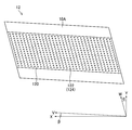
- FIG. 5 is a perspective view showing a configuration example of the inkjet head.
- the inkjet head 10 shown in the figure has a structure in which a plurality of head modules 12 are connected in a row along the longitudinal direction of the inkjet head 10.
- the plurality of head modules 12 are integrated and supported by using the head frame 100.
- the inkjet head 10 is a line head in which a plurality of nozzles are arranged over a length corresponding to the entire width of the paper in the paper width direction. Note that the nozzle is not shown in FIG.
- the nozzles are designated by reference numeral 122 and are shown in FIG.
- the paper width direction is a direction orthogonal to the paper transport direction in the printing apparatus.
- the planar shape of the nozzle surface 10A of the head module 12 is a parallelogram. Dummy plates 102 are attached to both ends of the head frame 100.
- the planar shape of the nozzle surface 10A of the inkjet head 10 is rectangular as a whole when the head module 12 and the dummy plate 102 are combined.
- a flexible board 104 is attached to the head module 12.
- the flexible substrate 104 is a wiring member that transmits a drive voltage supplied to the head module 12.
- One end of the flexible substrate 104 is electrically connected to the head module 12, and the other end is electrically connected to the drive voltage supply circuit.
- the drive voltage supply circuit is not shown.
- FIG. 6 is a plan view showing an example of nozzle arrangement of the inkjet head shown in FIG.
- the central portion of the nozzle surface 10A of the head module 12 includes a strip-shaped nozzle arrangement portion 120.
- the nozzle arranging portion 106 functions as a substantial nozzle surface 10A.
- a plurality of nozzles 122 are arranged in the nozzle arrangement unit 120.
- the nozzle 122 includes a nozzle opening 124 formed on the nozzle surface 10A.
- a structural example of the nozzle 122 will be described later. In the following description, the arrangement of the nozzle 122 may be read as the arrangement of the nozzle opening 124.
- the head module 12 shown in FIG. 6 has an end face on the long side along the V direction having an inclination of an angle ⁇ with respect to the paper width direction shown by the reference numeral X, and a paper shown by the reference numeral Y. It has a plane shape of a parallelogram having an end face on the short side along the W direction having an inclination of an angle ⁇ with respect to the transport direction.
- a plurality of nozzles 122 are arranged in a matrix in the row direction along the V direction and the column direction along the W direction.
- the nozzles 122 may be arranged along the row direction along the paper width direction and along the column direction diagonally intersecting the paper width direction.
- the projected nozzle rows projected along the nozzle row direction of each nozzle 122 in the matrix arrangement are each nozzle at a density that achieves the maximum recording resolution in the nozzle row direction. It can be considered to be equivalent to a row of nozzles in which 122s are arranged at approximately equal intervals.
- the projection nozzle row is a nozzle row in which each nozzle 122 in the matrix arrangement is projected normally along the nozzle row direction.
- Approximately equidistant means that the drip points that can be recorded by the printing apparatus are substantially equidistant.
- the concept of equal spacing also includes those that are slightly spaced apart in consideration of at least one of the manufacturing error and the movement of the droplets on the substrate due to landing interference.
- the projected nozzle array corresponds to a substantial nozzle array.
- each nozzle 122 can be associated with a nozzle number representing a nozzle position in the order in which the projection nozzles are arranged along the nozzle array direction.
- the line type inkjet head 10 is illustrated, but it can also be applied to a serial type inkjet head.
- FIG. 7 is a vertical cross-sectional view showing the three-dimensional structure of the ejector of the inkjet head shown in FIG.
- the ejector 130 includes a nozzle 122, a pressure chamber 132 leading to the nozzle 122, and a piezoelectric element 134.
- the nozzle opening 124 communicates with the pressure chamber 132 via the nozzle flow path 136.
- the pressure chamber 132 communicates with the common branch flow path 140 via the individual supply passage 138.
- the diaphragm 142 forming the top surface of the pressure chamber 132 includes a conductive layer that functions as a common electrode corresponding to the lower electrode of the piezoelectric element 134.
- the illustration of the conductive layer is omitted.
- the pressure chamber 132, the wall portion of the other flow path portion, the diaphragm 142, and the like can be made of silicon.
- the material of the diaphragm 142 is not limited to silicon, but it can also be formed of a non-conductive material such as resin.
- the diaphragm 142 itself may be made of a metal material such as stainless steel to serve as a common electrode.
- the piezoelectric unimorph actuator is configured by the structure in which the piezoelectric element 134 is laminated on the diaphragm 142.
- a driving voltage is applied to the individual electrodes 144, which are the upper electrodes of the piezoelectric element 134, to deform the piezoelectric body 146, and the diaphragm 142 is bent to change the volume of the pressure chamber 132.
- the pressure change accompanying the volume change of the pressure chamber 132 acts on the ink, and the ink is ejected from the nozzle opening 124.
- the plan view shape of the pressure chamber 132 is not particularly limited, and may have various shapes such as a quadrangle or other polygonal shape, a circular shape, or an elliptical shape.
- the cover plate 148 shown in FIG. 7 is a member that maintains the movable space 150 of the piezoelectric element 134 and seals the periphery of the piezoelectric element 134.
- a supply side ink chamber and a collection side ink chamber are formed above the cover plate 148.
- the supply-side ink chamber is connected to the supply-side common main flow path via a continuous passage.
- the collection-side ink chamber is connected to the collection-side common main flow path via a continuous passage.
- the ejector shown in FIG. 7 has the same meaning as a ejection element, a printing element, and the like.
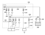
- FIG. 8 is a block diagram showing a configuration example of the ink supply unit.
- the ink supply unit 200 shown in the figure supplies ink to each head module 12, and circulates ink for each head module 12.
- Each head module 12 is connected to the supply manifold 230 via the supply individual flow path 210.
- the individual supply flow path 210 includes a supply flow path damper 212 and a supply flow path valve 214. In FIG. 8, only a part of the supply individual flow path 210 and the like is designated by a reference numeral.
- the supply flow path damper 212 suppresses the pulsation of ink passing through the individual supply flow path 210.
- the supply flow path valve 214 supplies and shuts off ink passing through the supply individual flow path 210 in response to a command signal transmitted from the control unit.
- Each head module 12 is connected to the circulation manifold 232 via the circulation individual flow path 220.
- the circulation individual flow path 220 includes a circulation flow path damper 222 and a circulation flow path valve 224.
- the circulation flow path damper 222 suppresses the pulsation of the ink passing through the circulation individual flow path 220.
- the circulation flow path valve 224 supplies and shuts off ink passing through the circulation individual flow path 220 in response to a command signal transmitted from the control unit.
- the supply manifold 230 is a primary storage flow path for ink supplied from the ink tank 240.
- the circulation manifold 232 is a primary storage flow path for ink that circulates ink from the inkjet head 10 to the ink tank 240.
- the supply manifold 230 and the circulation manifold 232 communicate with each other via the first bypass flow path 242 and the second bypass flow path 250.
- the first bypass flow path 242 includes a first valve 244.
- the second bypass flow path 250 includes a second valve 252 and a damper 254.
- the supply manifold 230 includes a supply pressure sensor 234.
- the circulation manifold 232 includes a circulation pressure sensor 236.
- the head control unit that controls the inkjet head 10 operates the supply pump 260 and the circulation pump 262 based on the pressure detection results of the supply pressure sensor 234 and the circulation pressure sensor 236 and the internal pressure setting of the inkjet head 10, and inside the inkjet head 10. Control the pressure.
- the internal pressure of the inkjet head 10 includes the negative pressure described above.
- liquid repellent film As the liquid repellent film 10B on the nozzle surface 10A shown in FIG. 1, a liquid repellent film containing a linear fluorine-containing silane coupling agent can be applied.
- a liquid-repellent film is a silicon compound in which the material of the nozzle plate is silicon and does not contain a fluorine atom, and the first organic film is formed from the silicon compound represented by the formula 1 or the formula 2 as a raw material.
- An inorganic oxide film can be formed on the organic film, and a linear fluorine-containing silane coupling agent can be used as a raw material to form a second organic film on the inorganic oxide film.
- the second organic film has liquid repellency against ink.
- X in formula 1 is any halogen, methoxy group, ethoxy group, acetoxy group or 2-methoxyethoxy group excluding fluorine, and R 2 is an alkyl group having 1 to 3 carbon atoms.
- R 1 is C m H 2 m when m is a natural number from 1 to 20.
- Z is a group containing any one of a methyl group, a vinyl group, an amino group, an epoxy group, a methacryl group, an acrylic group, a mercapto group, an isocyanate group, an acylthio group or a ureido group.
- R 3 , R 4 and R 5 in Formula 2 are alkyl groups having 1 to 3 carbon atoms.
- Silicon compounds have a boiling point of 20 ° C or higher and 350 ° C or lower.
- the linear fluorine-containing silane coupling agent is a compound represented by using the formula 3.
- X is any of halogen, methoxy group, ethoxy group, acetoxy group or 2-methoxyethoxy group
- R 7 is an alkyl group having 1 to 3 carbon atoms
- R 6 is p from 1 to 20. It is a C p H 2p group when it is a natural number up to, or a group containing a linear fluorocarbon chain and C q H 2q when q is a natural number from 1 to 20.
- Z is a group containing any one of a methyl group, a vinyl group, an amino group, an epoxy group, a methacryl group, an acrylic group, a mercapto group, an isocyanate group, an acylthio group, a ureido group or a trifluoromethyl group.
- a self-assembled monolayer may be applied to at least one of the first organic film and the second organic film.
- the first organic film can be formed by applying the vapor phase method.
- a silicon oxide film may be applied as the inorganic oxide film.
- the inorganic oxide film can be formed by applying the vapor phase method.
- the second organic film can be formed by applying the vapor phase method.
- the thickness of the first organic film and the thickness of the second organic film can be 0.5 nanometers or more and 30 nanometers or less.
- the thickness of the first organic film and the thickness of the second organic film are preferably 0.5 nanometers or more and 10 nanometers or less.
- the thickness of the first organic film and the thickness of the second organic film are more preferably 0.5 nanometer or more and 5 nanometer or less.
- the thickness of the liquid-repellent film 10B the thickness of the second organic film having liquid-repellent property against ink can be applied.
- the thickness of the liquid-repellent film 10B may be the thickness obtained by adding the thickness of the first organic film to the thickness of the second organic film. That is, the thickness of the liquid repellent film 10B can be 5 nanometers or more and 60 nanometers or less.
- FIG. 9 is a front view of the inkjet printing apparatus.
- FIG. 10 is a top view of the inkjet printing apparatus shown in FIG.
- the inkjet printing apparatus 300 includes a paper transport unit 302, a printing unit 304, and a maintenance unit 306.
- the paper transport unit 302 includes a printing drum 310.
- the inkjet printing device 300 includes a paper feeding unit and a paper discharging unit.
- the paper feeding unit supplies the paper used for printing to the paper conveying unit 302.
- the output section collects printed paper. It should be noted that the paper feed section and the paper discharge section are not shown.
- the printing drum 310 has a plurality of suction holes formed in the paper supporting area that supports the paper.
- the suction hole is connected to the suction pump via a gas flow path.
- the rotation support shaft 312 of the printing drum 310 is connected to the rotation shaft of the motor via a connecting member.
- the inkjet printing apparatus 300 rotates the rotation axis of the motor in a specified rotation direction based on a control signal to rotate the printing drum 310 in a specified rotation direction, and defines the paper supported by the paper support area of the printing drum 310. It is transported along the transport path of. In FIGS. 9 and 10, the paper support area, the suction hole, the gas flow path, the suction pump, and the connecting member are not shown.
- the printing unit 304 prints on the paper to be conveyed using the paper conveying unit 302.
- the printing unit 304 includes an inkjet head that ejects each of cyan ink, magenta ink, yellow ink, and black ink.
- the inkjet head 10C shown in FIG. 10 ejects cyan ink.
- the inkjet head 10M ejects magenta ink.
- the inkjet head 10Y ejects yellow ink.
- the inkjet head 10K ejects black ink.
- the inkjet head 10 is used as a general term for the inkjet head 10C and the like or as a term representing any one of the inkjet head 10C and the like.
- a drop-on-demand method is applied to the inkjet head 10.
- the inkjet head 10 controls ink ejection based on the ejection drive voltage supplied from the print control unit shown in FIG. Further, the inkjet head 10 controls the tickle based on the drive voltage for the tickle supplied from the print control unit.
- the maintenance unit 306 includes a head moving mechanism 320, a wiping unit 322, and a cap unit 324.
- the head moving mechanism 320 collectively moves the inkjet head 10C and the like.
- the head moving mechanism 320 includes a horizontal moving mechanism 330.
- the horizontal movement mechanism 330 includes a guide rail 332, a ball screw 334, a nut 336, a motor 338, and a pair of frames 340.
- the head moving mechanism 320 includes an elevating mechanism. The elevating mechanism raises and lowers the inkjet head 10C and the like at once. The elevating mechanism is not shown.
- the horizontal movement mechanism 330 reciprocates the inkjet head 10C and the like from the printing position to the capping position in a plane parallel to the horizontal plane along the horizontal direction.
- the printing position is a position directly above the printing drum 310, and is a position of the inkjet head 10C or the like when printing is performed.
- the capping position is a position directly above the cap portion 324, and is a position of the inkjet head 10C or the like at the time of capping.
- the inkjet head 10C and the like are integrally supported by using the frame 340.
- the frame 340 is connected to the nut.
- the motor 338 is operated to rotate the ball screw 334.
- the frame 340 connected to the nut 336 moves in the horizontal direction, and the inkjet head 10C and the like move in the horizontal direction and in a plane parallel to the horizontal plane.
- a control type motor whose rotation and stop can be controlled by using a command signal, such as a stepping motor and a servo motor, is applied.
- the wiping unit 322 includes a wiping device 20C, a wiping device 20M, a wiping device 20Y, and a wiping device 20K shown in FIG.
- the wiping device 20C wipes the nozzle surface 10A of the inkjet head 10C.
- the wiping device 20M, the wiping device 20Y, and the wiping device 20K wipe the nozzle surface 10A of the inkjet head 10M, the nozzle surface 10A of the inkjet head 10Y, and the nozzle surface 10A of the inkjet head 10K, respectively.
- the wiping device 20 shown in FIG. 1 and the like corresponds to any one of the wiping device 20C, the wiping device 20M, the wiping device 20Y, and the wiping device 20K shown in FIG.
- the wiping unit 322 shown in the embodiment corresponds to an example of the wiping processing unit.
- the cap portion 324 includes a cap 360C, a cap 360M, a cap 360Y, and a cap 360K.
- the cap 360C caps the inkjet head 10C.
- the cap 360M, the cap 360Y, and the cap 360K cap the inkjet head 10M, the inkjet head 10Y, and the inkjet head 10K, respectively.
- the frame 340 and the inkjet head 10C and the like shown by the broken lines in FIG. 9 indicate the inkjet head 10C and the like capped with the cap 360C.
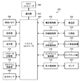
- FIG. 11 is a functional block diagram of the inkjet printing apparatus.
- the inkjet printing device 300 includes a system controller 400.
- the system controller 400 functions as an overall control unit that collectively controls each unit of the inkjet printing apparatus 300. Further, the system controller 400 functions as a calculation unit that performs various calculation processes.
- the system controller 400 may execute a program to control each part of the inkjet printing apparatus 300. Further, the system controller 400 functions as a memory controller that controls reading and writing of data in memories such as ROM (Read Only Memory) and RAM (Random access memory).
- ROM Read Only Memory
- RAM Random access memory
- the inkjet printing device 300 includes a communication unit 402 and an image memory 404.
- the communication unit 402 includes a communication interface (not shown).
- the communication unit 402 can send and receive data between the communication interface and the connected host computer 403.
- the image memory 404 functions as a temporary storage unit for various data including image data. Data is read / written from the image memory 404 through the system controller 400. The image data taken in from the host computer 403 via the communication unit 402 is temporarily stored in the image memory 404.
- the inkjet printing device 300 includes a transport control unit 410, a print control unit 412, a head movement control unit 414, a maintenance control unit 416, and a pressure control unit 418.
- the transport control unit 410 controls the operation of the paper transport unit 302 in response to a command from the system controller 400.
- the print control unit 412 controls the operation of the print unit 304 in response to a command from the system controller 400. That is, the print control unit 412 controls the ink ejection of the inkjet head 10 shown in FIG. 1 and the like.
- the print control unit 412 includes an image processing unit.
- the image processing unit forms dot data from the input image data.
- the image processing unit includes a color separation processing unit, a color conversion processing unit, a correction processing unit, and a halftone processing unit.
- the image processing unit, the color separation processing unit, the color conversion processing unit, the correction processing unit, and the halftone processing unit are not shown.
- the color separation processing unit performs color separation processing on the input image data.
- the color separation processing unit decomposes the input image data into RGB color data.
- R represents red.
- G represents green.
- B represents blue.
- the color conversion processing unit converts the image data for each color decomposed into red, green, and blue into cyan, magenta, yellow, and black corresponding to the ink color.
- the correction processing unit performs correction processing on the image data for each color converted to cyan, magenta, yellow, and black.
- Examples of the correction processing include a gamma correction processing, a density unevenness correction processing, an abnormality recording element correction processing, and the like.
- the halftone processing unit converts image data represented by a multi-gradation number such as 0 to 255 into dot data represented by a binary value or a multi-valued value of three or more values less than the number of gradations of the input image data. To do.
- a predetermined halftone processing rule is applied to the halftone processing unit.
- Examples of halftone processing rules include the dither method and the error diffusion method.
- the halftone processing rule may be changed according to the image formation conditions, the content of the image data, and the like.
- the print control unit 412 includes a waveform generation unit (not shown), a waveform storage unit, and a drive circuit (not shown).
- the waveform generator generates a waveform of the drive voltage.
- the waveform storage unit stores the waveform of the drive voltage.
- the drive circuit generates a drive voltage having a drive waveform corresponding to the dot data.
- the drive circuit supplies the drive voltage to the inkjet head 10.
- the ejection timing and the ink ejection amount of each pixel position are determined based on the dot data generated through the processing using the image processing unit.
- a control signal for determining the ejection timing of each pixel position, the drive voltage according to the ink ejection amount, and the ejection timing of each pixel is generated.
- a driving voltage is supplied to the inkjet head 10, and ink is ejected from the inkjet head 10.
- the ink ejected from the inkjet head 10 forms dots.
- the head movement control unit 414 operates the head movement mechanism 320 in cooperation with the maintenance control unit 416 in response to a command from the system controller 400.
- the head movement control unit 414 may include an elevating control unit that controls the elevating mechanism and a horizontal movement control unit that controls the horizontal movement mechanism 330.
- the head movement control unit 414 shown in the embodiment corresponds to an example of a component of the head control unit.
- the maintenance control unit 416 operates the maintenance unit 306 in response to a command from the system controller 400.
- the maintenance control unit 416 may include a wiping control unit that controls the wiping unit 322 and a cap control unit that controls the cap unit 324.
- the maintenance control unit 416 may include a head movement control unit 414.
- the maintenance control unit 416 raises and lowers the wiping unit 322 according to the position of the inkjet head 10 in the head movement path. That is, the maintenance control unit 416 moves the wiping unit 322 to the wiping processing position where the web sheet 22 of the wiping unit 322 comes into contact with the nozzle surface 10A of the inkjet head 10 during the period in which the inkjet head 10 passes through the wiping position of the wiping unit 322. Raise. After the inkjet head 10 has passed the wiping position of the wiping portion 322, the wiping portion 322 is lowered from the wiping processing position to the standby position.
- the maintenance control unit 416 derives the position of the inkjet head 10 in the head movement path by using the moving speed of the inkjet head 10 and the elapsed period from the start of movement of the inkjet head 10.
- the maintenance control unit 416 controls the tickle of the inkjet head 10 in conjunction with the print control unit 412 according to the position of the inkjet head 10 in the head movement path.
- the maintenance control unit 416 performs tickling of the inkjet head 10 in conjunction with the print control unit 412 when the inkjet printing device 300 is switched to the maintenance mode.
- the maintenance control unit 416 controls the stop and restart of the tickle for each head module 12 in conjunction with the print control unit 412 in the maintenance mode.
- the print control unit 412 and the maintenance control unit 416 shown in the embodiment correspond to an example of the components of the head control unit.
- the pressure control unit 418 adjusts the internal pressure of the inkjet head 10 in response to a command transmitted from the system controller 400. That is, the pressure control unit 418 controls the operation of the pump 420 based on the pressure detection result transmitted from the pressure sensor 440.
- the pressure control unit 418 controls the operation of the pump 420 based on the pressure detection result transmitted from the pressure sensor 440.
- the pump 420 shown in FIG. 11 corresponds to the supply pump 260 and the circulation pump 262 shown in FIG. Further, the pressure sensor 440 corresponds to the supply pressure sensor 234 and the circulation pressure sensor 236.
- the pressure control unit 418 shown in the embodiment corresponds to an example of the head control unit. Further, the pressure control unit 418 corresponds to an example of a negative pressure setting unit.
- the inkjet printing device 300 includes an operation unit 430.
- the operation unit 430 includes operation members such as operation buttons, a keyboard, and a touch panel.
- the operation unit 430 may include a plurality of types of operation members. The illustration of the operating member is omitted.
- the information input via the operation unit 430 is sent to the system controller 400.
- the system controller 400 executes various processes according to the information sent from the operation unit 430.
- the inkjet printing device 300 includes a display unit 432.
- the display unit 432 includes a display device such as a liquid crystal panel and a display driver. The display device and display driver are not shown.
- the display unit 432 causes the display device to display various information such as various setting information and abnormality information of the device in response to a command from the system controller 400.
- the inkjet printing device 300 includes a parameter storage unit 434.
- the parameter storage unit 434 stores various parameters used in the inkjet printing apparatus 300.
- Various parameters stored in the parameter storage unit 434 are read out via the system controller 400 and set in each unit of the device.
- the inkjet printing device 300 includes a program storage unit 436.
- the program storage unit 436 stores programs used in each unit of the inkjet printing apparatus 300.
- Various programs stored in the program storage unit 436 are read out via the system controller 400 and executed in each unit of the device.
- Each control unit such as the system controller 400 and the transport control unit 410 shown in FIG. 11 executes a specified program using the hardware described below to realize the function of the inkjet printing device 300.
- Various processors can be applied to the hardware of each control unit. Examples of processors include a CPU (Central Processing Unit) and a GPU (Graphics Processing Unit). The CPU executes a program and functions as various processing units.
- CPU Central Processing Unit
- GPU Graphics Processing Unit
- the GPU is a processor specialized in image processing.
- an electric circuit combining an electric circuit element such as a semiconductor element is applied.
- Each control unit includes a ROM in which a program or the like is stored and a RAM in which a work area for various operations or the like is stored.
- Two or more processors may be applied to one control unit.
- the two or more processors may be the same type of processor or different types of processors. Further, one processor may be applied to a plurality of control units.
- the paper applied to the inkjet printing apparatus 300 may be sheet-fed paper or continuous paper.
- As the paper not only a paper medium but also a resin sheet, a metal sheet and the like can be applied.
- the paper transport unit 302 of the inkjet printing apparatus 300 may apply a mode in which the paper is transported in a plane by using a transport belt or the like.
- the inkjet printing device 300 that prints an image on paper is illustrated as an example of the liquid ejection device, but the function of the inkjet printing device 300 according to the present embodiment is to use a liquid having functionality on a substrate or the like. It can also be realized in a pattern forming apparatus that forms a pattern.
- FIG. 12 is a flowchart showing the procedure of the head maintenance method according to the embodiment.
- the maintenance mode is executed.
- Maintenance of the inkjet head 10 may include wiping the nozzle surface 10A, suction processing using the cap portion 324, and purging treatment using the cap portion 324.
- FIG. 12 illustrates the procedure for wiping the nozzle surface 10A in the maintenance of the inkjet head 10.
- the wiping process of the nozzle surface 10A of the inkjet head 10 is started.
- the maintenance control unit 416 shown in FIG. 11 cooperates with the pressure control unit 418 to set a negative pressure corresponding to the wiping process of the nozzle surface 10A.
- the process proceeds to the tickle start step S12.
- the maintenance negative pressure setting step S10 shown in the embodiment corresponds to an example of the negative pressure applying step.
- tickle start step S12 the maintenance control unit 416 cooperates with the print control unit 412 to start the tickle of all the head modules 12. After the tickle start step S12, the process proceeds to the wiping target determination step S14.
- the tickle start step S12 described in the embodiment corresponds to an example of a non-discharge drive step.
- the maintenance control unit 416 determines whether or not all the head modules 12 provided in the inkjet head 10 are the wiping target head modules 12A in accordance with the specified order.
- the wiping target determination step S14 when the maintenance control unit 416 determines that the head module 12 to be determined is not the wiping target head module 12A, a No determination is made. In the case of No determination, the wiping target determination step S14 is continued until the result is Yes in the wiping target determination step S14.
- the wiping target determination step S14 when the maintenance control unit 416 determines that the head module 12 to be determined is the wiping target head module 12A, a Yes determination is made. In the case of Yes determination, the process proceeds to the tickle stop step S16.
- tickle stop step S16 the maintenance control unit 416 cooperates with the print control unit 412 to stop the tickle for the head module 12A to be wiped. After the tickle stop step S16, the process proceeds to the wiping step S18.
- the tickle stop step S16 described in the embodiment corresponds to an example of a non-discharge drive step.
- the maintenance control unit 416 wipes the nozzle surface 10A of the head module 12A to be wiped.
- the process proceeds to the wiping end determination step S20.
- the wiping end determination step S20 the maintenance control unit 416 determines whether or not the wiping process of the wiping target head module 12A is completed.
- the wiping end determination step S20 when the maintenance control unit 416 determines that the wiping process of the wiping target head module 12A has not been completed, a No determination is made. In the case of No determination, the wiping end determination step S20 is continued until a Yes determination is made in the wiping end determination step S20.
- the wiping end determination step S20 when the maintenance control unit 416 determines that the wiping process of the wiping target head module 12A is completed, a Yes determination is made. In the case of Yes determination, the process proceeds to the tickle restart step S22.
- the maintenance control unit 416 cooperates with the print control unit 412 to restart the tickle of the wiping target head module 12A for which the wiping process has been completed. After the tickle restart step S22, the process proceeds to the all module wiping end determination step S24.
- the maintenance control unit 416 determines whether or not the wiping process of the nozzle surface 10A for all the head modules 12 has been completed.
- the all module wiping end determination step S24 when the maintenance control unit 416 determines that the wiping process of the nozzle surface 10A for all the head modules 12 has not been completed, a No determination is made. In the case of No determination, the process proceeds to the wiping target determination step S14, and each step from the wiping target determination step S14 to the all module wiping end determination step S24 is repeatedly carried out until a Yes determination is made in the all module wiping end determination step S24. ..
- the all module wiping end determination step S24 when the maintenance control unit 416 determines that the wiping process of the nozzle surface 10A for all the head modules 12 has been completed, a Yes determination is made. In the case of Yes determination, the process proceeds to the tickle end step S26.
- the maintenance control unit 416 cooperates with the print control unit 412 to end the tickle for all the head modules 12. After the tickle end step S26, the process proceeds to the printing negative pressure setting step S28.
- the maintenance control unit 416 cooperates with the pressure control unit 418 to set the negative pressure of the inkjet head 10 to the negative pressure in the printing mode. After the printing negative pressure setting step S28, a specified end process is performed, and the maintenance control unit 416 ends the wiping process of the nozzle surface 10A.
- a head device can be configured by applying some of the components of the inkjet printing device 300 described with reference to FIGS. 9 to 11. That is, the head device according to the embodiment includes an inkjet head 10 and a head control unit.
- the head control unit includes a system controller 400, a communication unit 402, a print control unit 412, and a pressure control unit 418 shown in FIG.
- the head device performs tickle control of the inkjet head 10 in cooperation with the maintenance device of the inkjet head 10.
- Programs corresponding to the head device, inkjet printing device and head maintenance method disclosed herein can be configured. That is, it is possible to configure a program that allows the computer to realize the functions of each part shown in FIG. 11 and the like and the functions of each part shown in FIG.
- the computer is provided with a negative pressure setting function corresponding to the maintenance negative pressure setting process S10 and the printing negative pressure setting process S28 shown in FIG. 12, and a tickle switching function corresponding to the tickle start process S12, the tickle stop process S16, and the tickle end process S26.
- the program to be realized can be constructed.
- the constituent requirements can be appropriately changed, added, or deleted without departing from the gist of the present invention.
- the present invention is not limited to the embodiments described above, and many modifications can be made by a person having ordinary knowledge in the art within the technical idea of the present invention.
Landscapes
- Ink Jet (AREA)
Abstract
ノズル面の払拭処理に起因するノズル面の撥液膜の性能低下を抑制し得る、ヘッド装置、液体吐出装置及びヘッドメンテナンス方法を提供する。ノズル面(10A)に撥液膜(10B)が形成されるインクジェットヘッド(10)、ヘッド制御部を備え、ヘッド制御部はノズル面の払拭処理が実施される際に、ノズル内の液体に負圧を付与し、かつノズル内の液体を吐出させずに振動させる非吐出駆動を実施し、払拭処理に使用される払拭部材(22)を接触させる払拭対象ノズル(12A)は非吐出駆動を停止させる。
Description
本発明はヘッド装置、液体吐出装置及びヘッドメンテナンス方法に関する。
インクジェットヘッドを備えたインクジェット印刷装置が知られている。インクジェット印刷装置は、ノズルからインクを吐出させない程度にメニスカスを振動させる駆動を実施して、ノズル内のインクの乾燥に起因するインクの劣化を抑制している。かかる駆動は、ティックル及びメニスカス揺らしなどと呼ばれる。
インクジェット印刷装置は、インクジェットヘッドのノズル面のワイピングを実施して、ノズル面に付着したインクミスト等の異物を除去し、ノズル面への異物の付着に起因する吐出性能の低下を抑制している。ワイピングは、不織布等が適用されるウェブシート及びゴム等が適用されるブレードなどの払拭部材が適用される。
ワイピングの際にティックルが実施される場合、ティックルが実施されない場合と比較して、ノズルから払拭部材へのインクの引き出し量が多くなり得る。ノズル面に形成される撥液膜を削り易い成分を有するインクが適用されるインクジェットヘッドでは、ワイピングの実施に起因して撥液膜の劣化が促進される。
特許文献1は、ノズル面を払拭するワイパーを備えたインクジェット印刷装置が記載されている。同文献に記載の装置は、ワイパーを用いてノズル面を払拭する際に、ワイパーが接触しないノズルを駆動して、ワイパーが接触するノズルに連通する圧力室の圧力を低下させる。これにより、ワイパーが接触するノズルのメニスカスをノズルの奥側へ引き込ませて、メニスカスの破壊に起因するインクの漏れ出しを抑制する。
特許文献2は、ノズル面を払拭するワイパーを備えたインクジェット印刷装置が記載されている。同文献に記載の装置は、吐出しない程度の脈動をインクに加えてワイピングを実施し、拭き残し等のワイピングの不具合を低減する。
特許文献3は、インクジェットヘッドのメンテナンス装置を備えるインクジェット印刷装置が記載されている。同文献に記載の装置は、インクジェットヘッドのメンテナンスの際の負圧がマイナス0.8キロパスカルからマイナス0.1キロパスカルの範囲に設定される。
しかしながら、特許文献1に記載の発明は、ワイパーが接触しないノズルからインクが吐出され、ノズルから吐出されたインクがワイパーへ付着してしまう。特許文献2に記載の発明は、ワイピングの際にワイパーへインクを付着させている。
特許文献3に記載の発明は、ワイピングの際にノズルからインクを漏れ出させている。ノズルから漏れ出したインクがワイパーへ付着する。このような場合、インクが付着したワイパーを用いてワイピングを実施した際に、インクに含有する粒子がノズル面の撥液膜を削り、撥液膜に摩耗が生じ得る。
本発明はこのような事情に鑑みてなされたもので、ノズル面の払拭処理に起因するノズル面の撥液膜の摩耗を抑制し得る、ヘッド装置、液体吐出装置及びヘッドメンテナンス方法を提供することを目的とする。
上記目的を達成するために、次の発明態様を提供する。
第1態様に係るヘッド装置は、ノズル面に撥液膜が形成されるインクジェットヘッドと、インクジェットヘッドを制御するヘッド制御部と、を備え、ヘッド制御部は、ノズル面の払拭処理が実施される際に、ノズル内の液体に負圧を付与し、かつノズル内の液体を吐出させずに振動させる非吐出駆動を実施し、払拭処理に使用される払拭部材を接触させる払拭対象ノズルは、非吐出駆動を停止させるヘッド装置である。
第1態様によれば、払拭対象ノズルは非吐出駆動を停止させる。これにより、払拭部材を接触させたノズルからノズル面へのノズル内の液体の引き出しが抑制され、ノズル面に形成される撥液膜の摩耗を抑制し、インクジェットヘッドの性能低下を抑制し得る。
払拭部材は、液体を吸収する機能を有する吸収部材を適用し得る。吸収部材の例としてウェブシートが挙げられる。
ノズル面の払拭は、停止させた払拭部材に対してインクジェットヘッドを移動させて実施してもよいし、停止させたインクジェットヘッドに対して払拭部材を移動させて実施してもよい。
第2態様は、第1態様のヘッド装置において、ヘッド制御部は、払拭部材が非接触の非対象ノズルに対する非吐出駆動の実施を継続する構成としてもよい。
第2態様によれば、非対象ノズルは非吐出駆動が実施される。これにより、非対象ノズル内の液体の乾燥が抑制される。
第3態様は、第1態様のヘッド装置において、インクジェットヘッドは、複数のヘッドモジュールを備え、複数のヘッドモジュールを繋ぎ合わせた構造を有し、ヘッド制御部は、払拭処理が実施される際に、払拭対象ノズルが属する払拭対象ヘッドモジュールの非吐出駆動を停止させる構成としてもよい。
第3態様によれば、払拭処理に応じた非吐出駆動の制御をヘッドモジュールごとに実施し得る。
第4態様は、第3態様のヘッド装置において、ヘッド制御部は、払拭対象ヘッドモジュール以外の非対象ヘッドモジュールに対する非吐出駆動の実施を継続する構成としてもよい。
第4態様によれば、非対象ヘッドモジュールは非吐出駆動が実施される。これにより、非対象ヘッドモジュールに属するノズル内の液体の乾燥が抑制される。
第5態様は、第3態様のヘッド装置において、ヘッド制御部は、払拭対象ヘッドモジュールに対して払拭部材が接触し始めるタイミングよりも前に、払拭対象ヘッドモジュールの非吐出駆動を停止させる構成としてもよい。
第5態様によれば、払拭部材とノズル内のインクとの接触をより効果的に抑制し得る。
隣り合う二つのヘッドモジュールを払拭対象ヘッドモジュールとし得る。先に払拭処理が実施される払拭対象ヘッドモジュールの払拭処理中に、後に払拭処理が実施される払拭対象ヘッドモジュールは非吐出駆動を停止させてもよい。換言すると、先の払拭対象ヘッドモジュールに払拭部材が接触する任意のタイミングにおいて、次の払拭対象ヘッドモジュールの非吐出駆動を停止させてもよい。
第6態様は、第5態様のヘッド装置において、ヘッド制御部は、払拭対象ヘッドモジュールに対して払拭部材が接触し始めるタイミングの0.2秒以上前に、払拭対象ヘッドモジュールの非吐出駆動を停止させる構成としてもよい。
第6態様によれば、払拭対象ヘッドモジュールのノズル面へ払拭部材が接触する前に、払拭対象ヘッドモジュールの非吐出駆動を確実に停止させ得る。
第7態様は、第4態様から第6態様のいずれか一態様のヘッド装置において、ヘッド制御部は、払拭対象ヘッドモジュールに対して払拭部材が接触し終わるタイミングの後は、払拭対象ヘッドモジュールの非吐出駆動を実施させる構成としてもよい。
第7態様によれば、払拭部材とインクとの接触が確実に抑制され、かつ払拭処理が終了したヘッドモジュールに属するノズル内の液体の乾燥が抑制される。
第8態様は、第7態様のヘッド装置において、ヘッド制御部は、払拭対象ヘッドモジュールに対して払拭部材が接触し終わるタイミングの0.2秒以上後に、払拭対象ヘッドモジュールの非吐出駆動を実施させる構成としてもよい。
第8態様によれば、払拭部材とインクとの接触がより確実に抑制され、かつ払拭処理が終了したヘッドモジュールに属するノズル内の液体の乾燥がより確実に抑制される。
第9態様は、第1態様から第7態様のいずれか一態様のヘッド装置において、負圧を設定する負圧設定部であり、払拭処理の際の負圧を非吐出駆動の停止の際にノズルから液体が引き出されない範囲に設定する構成としてもよい。
第9態様によれば、払拭対象ノズルからノズル面への液体の引き出しがより確実に抑制される。
第10態様は、第9態様のヘッド装置において、負圧設定部は、払拭処理の際の負圧をマイナス5000キロパスカル以上マイナス500キロパスカル以下に設定する構成としてもよい。
第10態様によれば、払拭部材とノズル内のインクとの接触がより確実に抑制される。
第11態様は、第1態様から第10態様のいずれか一態様のヘッド装置において、インクジェットヘッドは、カーボンブラックを含有する液体及び酸化チタンを含有する液体の少なくともいずれかが使用される構成としてもよい。
第11態様によれば、撥液膜を削り易い粒子を含む液体が適用されるインクジェットヘッドにおいて、撥液膜の摩耗を抑制し得る。
カーボンブラックを含有する液体の例として黒インクが挙げられる。酸化チタンを含有する液体の例として白インクが挙げられる。
第12態様に係る液体吐出装置は、ノズル面に撥液膜が形成されるインクジェットヘッドと、インクジェットヘッドを制御するヘッド制御部と、ノズル面の払拭処理を実施する払拭処理部と、を備え、ヘッド制御部は、払拭処理部を用いてノズル面の払拭処理が実施される際に、ノズル内の液体に負圧を付与し、かつノズル内の液体を吐出させずに振動させる非吐出駆動を実施し、払拭処理に使用される払拭部材を接触させる払拭対象ノズルは、非吐出駆動を停止させる液体吐出装置である。
第12態様によれば、第1態様と同様の効果を得ることができる。
第12態様において、第2態様から第11態様で特定した事項と同様の事項を適宜組み合わせることができる。その場合、ヘッド装置において特定される処理や機能を担う構成要素は、これに対応する処理や機能を担う液体吐出装置の構成要素として把握することができる。
第13態様に係るヘッドメンテナンス方法は、ノズル面に撥液膜が形成されるインクジェットヘッドのノズル面の払拭処理を実施するヘッドメンテナンス方法であって、ノズル内の液体に負圧を付与する負圧付与工程と、ノズル内の液体を吐出させずに振動させる非吐出駆動を実施する非吐出駆動工程と、を含み、非吐出駆動工程は、払拭処理に使用される払拭部材を接触させる払拭対象ノズルに対する非吐出駆動を停止させるヘッドメンテナンス方法である。
第13態様によれば、第1態様と同様の効果を得ることができる。
第13態様において、第2態様から第11態様で特定した事項と同様の事項を適宜組み合わせることができる。その場合、ヘッド装置において特定される処理や機能を担う構成要素は、これに対応する処理や機能を担うヘッドメンテナンス方法の構成要素として把握することができる。
本発明によれば、払拭対象ノズルは非吐出駆動を停止させる。これにより、払拭部材を接触させたノズルからノズル面へのノズル内の液体の引き出しが抑制され、ノズル面に形成される撥液膜の摩耗を抑制し、インクジェットヘッドの性能低下を抑制し得る。
以下、添付図面に従って本発明の好ましい実施の形態について詳説する。本明細書では、同一の構成要素には同一の参照符号を付して、重複する説明は適宜省略する。
[ヘッドメンテナンス方法]
図1は実施形態に係るヘッドメンテナンス方法の模式図である。図1に示すヘッドメンテナンスは、インクジェットヘッド10のノズル面10Aを払拭する払拭処理である。ノズル面10Aは撥液膜10Bが形成される。
図1は実施形態に係るヘッドメンテナンス方法の模式図である。図1に示すヘッドメンテナンスは、インクジェットヘッド10のノズル面10Aを払拭する払拭処理である。ノズル面10Aは撥液膜10Bが形成される。
インクジェットヘッド10は、複数のヘッドモジュール12を長手方向に沿って一列に繋ぎ合わせた構造を有する。インクジェットヘッド10の長手方向は、図1に示すヘッド移動方向に対して平行となる方向である。
ここで、本明細書における平行という用語は、厳密には交差する二方向が平行と同様の作用効果が得られる実質的な平行を含み得る。直交についても同様であり、実質的な直交を含み得る。なお、図1に図示したヘッドモジュール12の数は任意の数であり、ヘッドモジュール12の数は図1に示す態様に限定されない。
払拭装置20は、走行させたウェブシート22をインクジェットヘッド10のノズル面10Aへ接触させて、ノズル面10Aを払拭する。払拭装置20は、押圧ローラ24及び付勢部26を備える。
払拭装置20は、ロール状のウェブシート22を収納する収納部を備える。払拭装置20は、使用後のウェブシート22を巻き取り回収する回収部を備える。なお、収納部及び回収部の図示を省略する。
押圧ローラ24はノズル面10Aへウェブシート22を接触させる際にウェブシート22を支持する。押圧ローラ24はウェブシート22の走行に応じて従動回転する。図1に示す矢印線は、押圧ローラ24の回転方向を示す。押圧ローラ24と接触するウェブシート22の走行方向は、押圧ローラ24の回転方向と一致する。
付勢部26は、押圧ローラ24に対してノズル面10Aへ向かう力を付与し、ノズル面10Aに向けてウェブシート22を付勢させる。付勢部26はバネ等の弾性部材を適用し得る。
図1に示すヘッドメンテナンス方法は、ヘッド移動方向についてインクジェットヘッド10を移動させ、位置を固定した払拭装置20においてウェブシート22を走行させる。ノズル面10Aの位置において、ウェブシート22の走行方向はインクジェットヘッド10の移動方向に対する反対方向である。これにより、ノズル面10Aの清掃効果が向上し得る。
インクジェットヘッド10は、メンテナンス処理中など非印刷の際にティックルが実施される。これにより、非印刷の際にノズル内のインクの乾燥が抑制される。なお、図1ではノズルの図示を省略する。ノズルは符号122を付して図7に図示する。
ティックルは、ノズルからインクを吐出させずにノズル内のインクを振動させる処理である。インクの吐出とは、規定範囲の体積を有するインクがノズル内のインクから分裂して、液滴状態でノズルから放出される状態である。ティックルは、各ノズルに対応する圧力発生素子に対して、吐出の際の駆動電圧よりも低い駆動電圧の印加を実施して実現し得る。なお、実施形態に示すティックルは非吐出駆動の一例に相当する。
インクの吐出には、規定範囲未満の体積を有するミスト状態のインクをノズルから放出させ、複数のミスト状態のインクをノズルの外部で合一させて、規定範囲の体積を有する液滴状態のインクとする態様を含み得る。
ノズル面10Aの払拭処理の対象である払拭対象ヘッドモジュール12Aは、払拭対象ヘッドモジュール12Aの全てのノズルについてティックルを停止させる。払拭対象ヘッドモジュール12A以外のヘッドモジュール12は、ティックルの実施を継続させる。ノズル面10Aの払拭処理が終了したヘッドモジュール12は、ティックルの実施が再開される。
インクジェットヘッド10は、ヘッド移動方向における最も下流側の位置のヘッドモジュール12から順に、ノズル面10Aの払拭処理が実施される。ヘッドモジュール12ごとにティックルのオンオフが実施される。
これにより、払拭対象ヘッドモジュール12Aのノズルからノズル面へのインクの引き出しが抑制され、インクに含有する顔料の撥液膜10Bへの接触に起因する撥液膜10Bの摩耗を抑制し得る。
特に、カーボンブラックを含有する黒インク及び酸化チタンを含有する白インクは、他の顔料を含有するインクと比較して、撥液膜10Bの摩耗を進行させ得る。本実施形態に示すヘッドメンテナンス方法は、カーボンブラックを含有する黒インクが適用されるインクジェットヘッド10及び酸化チタンを含有する白インクが適用されるインクジェットヘッド10に好適である。
なお、実施形態に示す払拭対象ヘッドモジュール12Aに属するノズルは、払拭対象ノズルの一例に相当する。実施形態に示す払拭対象ヘッドモジュール12A以外のヘッドモジュール12は払拭対象ヘッドモジュール以外の非対象ヘッドモジュールの一例に相当する。実施形態に示す払拭対象ヘッドモジュール12A以外のヘッドモジュール12に属するノズルは、払拭部材が非接触の非対象ノズルの一例に相当する。
図2は図1に示すヘッドメンテナンス方法の変形例の模式図である。図2に示すように、払拭対象ヘッドモジュール12Aについて、ティックルを停止させないノズルを設定してもよい。図2に示すティックル継続領域12Bは、ティックルを停止させないノズルが配置される。ティックル継続領域12Bに属するノズルは、ティックルを停止させずに、ティックルが継続される。
ティックル継続領域12Bは、インクジェットヘッド10の移動速度及び払拭対象ヘッドモジュール12Aの払拭開始タイミングに基づいて導出される、払拭対象ヘッドモジュール12Aにおける払拭装置20の位置に応じて規定し得る。ここで、速度という用語は、速度の絶対値を表す速さを含み得る。なお、実施形態に示すティックル継続領域12Bに属するノズルは、払拭部材が非接触の非対象ノズルの一例に相当する。
図3はティックル停止タイミングを示す模式図である。図3は、時系列に沿って、タイミングt11、タイミングt12、タイミングt13及びタイミングt14まで順に、ティックルの実施又は停止が遷移することを示す。
ヘッドモジュール12に付したONはティックルの実施を示す。OFFはティックルの停止を示す。なお、符号22Aを付した四角形はウェブシート接触領域を示す。ウェブシート接触領域22Aはノズル面10Aにおいてウェブシート22が接触する領域である。
図3に示すインクジェットヘッド10は、ヘッドモジュール12の平面形状が平行四辺形であり、隣り合うヘッドモジュール12の間の境界線が払拭方向に対して傾いている。なお、払拭方向はインクジェットヘッド10の移動方向と同義である。
各ヘッドモジュール12は、ウェブシート22が通過し始める前にティックルを停止させる。タイミングt11では、払拭対象ヘッドモジュール12Aのティックルを停止させ、かつ、払拭対象ヘッドモジュール12Aの次に払拭対象となる払拭非対象のヘッドモジュール12Cのティックルを停止させる。
すなわち、払拭対象ヘッドモジュール12Aの次に払拭対象となる払拭非対象のヘッドモジュール12Cは、先に払拭対象となっている払拭対象ヘッドモジュール12Aの払拭処理中にティックルが停止さる。
換言すると、払拭対象ヘッドモジュール12Aにウェブシート22が接触している任意のタイミングにおいて、次に払拭対象となる払拭非対象のヘッドモジュール12Cのティックルを停止させてもよい。
タイミングt12及びタイミングt13では、インクジェットヘッド10の移動に応じて、隣り合う二つの払拭対象ヘッドモジュール12Aにウェブシート22が接触する。タイミングt11において、次に払拭対象となる払拭非対象のヘッドモジュール12Cは、タイミングt12及びタイミングt13において、払拭対象ヘッドモジュール12Aとなる。換言すると、タイミングt12及びタイミングt13では、隣り合う二つのヘッドモジュール12が払拭対象ヘッドモジュール12Aとされる。
タイミングt14では、タイミングt12及びタイミングt13において隣り合う二つの払拭対象ヘッドモジュール12Aのうち、ヘッド移動方向の上流側の位置の払拭対象ヘッドモジュール12Aのティックルが再開される。
タイミングt14では、払拭対象ヘッドモジュール12Aをウェブシート22が完全に通過した後に、払拭対象ヘッドモジュール12Aであった払拭非対象のヘッドモジュール12のティックルが再開される。このようにして、ノズル面10Aの払拭処理が実施される全期間において、ウェブシート22とノズル内のインクとの接触を確実に避けることが可能となる。
図4はティックル停止の具体例を示す模式図である。同図には任意のモジュールにおけるティックルの停止及び再開を時系列に沿って示す。タイミングt21は接触開始タイミングtsの0.2秒以上前のタイミングである。接触開始タイミングtsは、払拭対象ヘッドモジュール12Aとウェブシート22との接触が開始されるタイミングである。
タイミングt22は、接触開始タイミングtsの0.2秒前のタイミングである。タイミングt22までに、払拭対象ヘッドモジュール12Aのティックルが停止される。すなわち、接触開始タイミングtsの0.2秒以上前に、払拭対象ヘッドモジュール12Aのティックルが停止される。
タイミングt23は接触開始タイミングtsである。タイミングt24は接触終了タイミングteである。タイミングt25は接触終了タイミングteの0.2秒後のタイミングである。タイミングt25では、払拭対象ヘッドモジュール12Aはティックルの停止が維持される。
t26は接触終了タイミングteの0.2秒以上後の任意のタイミングである。払拭対象ヘッドモジュール12Aであったヘッドモジュール12は、接触終了タイミングteの0.2秒以上後の任意のタイミングにおいてティックルが再開される。
すなわち、各ヘッドモジュール12は、ウェブシート22が接触を開始する接触開始タイミングtsよりも0.2秒前までにティックルが停止され、ウェブシート22が接触を終了する接触終了タイミングteの0.2秒後よりも後にティックルが再開される。
一つのヘッドモジュール12における払拭処理期間は、1.0秒から5.0秒までの任意の期間を設定し得る。接触開始タイミングtsに対するティックルの終了タイミングの先行期間は、一つのヘッドモジュール12における払拭処理期間に対して4.0パーセントから20パーセントまでの任意の期間を設定し得る。接触終了タイミングteに対するティックル再開の遅延期間も同様である。
[インクジェットヘッドの内部圧力制御]
本実施形態に示すインクジェットヘッド10は、内部のインクに負圧が付与される。ノズル面10Aの払拭処理の際の負圧は、ティックルを停止させた場合にノズルからノズル面へインクが引き出されない範囲に設定される。ノズル面10Aの払拭処理の際の負圧の例として、マイナス5000キロパスカル以上マイナス500キロパスカル以下の範囲が挙げられる。
本実施形態に示すインクジェットヘッド10は、内部のインクに負圧が付与される。ノズル面10Aの払拭処理の際の負圧は、ティックルを停止させた場合にノズルからノズル面へインクが引き出されない範囲に設定される。ノズル面10Aの払拭処理の際の負圧の例として、マイナス5000キロパスカル以上マイナス500キロパスカル以下の範囲が挙げられる。
ノズル面10Aの払拭処理の際の負圧は、印刷の際の負圧に対して上げてもよいし、印刷の際の負圧と一致させてもよい。負圧を上げるとは、負圧の絶対値を上げることを意味し、圧力を下げると同義である。
[作用効果]
実施形態に係るヘッドメンテナンス方法によれば、以下の作用効果を得ることが可能である。
実施形態に係るヘッドメンテナンス方法によれば、以下の作用効果を得ることが可能である。
〔1〕
ノズル面10Aに撥液膜10Bが形成されるインクジェットヘッド10を払拭する際に、ウェブシート22が接触するノズルのティックルを停止させる。これにより、ノズル面10Aを払拭する際にノズルとウェブシート22との接触に起因するノズルからノズル面へのインクの引き出しが抑制され、撥液膜10Bの摩耗が抑制される。
ノズル面10Aに撥液膜10Bが形成されるインクジェットヘッド10を払拭する際に、ウェブシート22が接触するノズルのティックルを停止させる。これにより、ノズル面10Aを払拭する際にノズルとウェブシート22との接触に起因するノズルからノズル面へのインクの引き出しが抑制され、撥液膜10Bの摩耗が抑制される。
〔2〕
ウェブシート22と非接触のノズルはティックルが継続される。これにより、ウェブシート22と非接触のノズル内のインクの乾燥が抑制される。
ウェブシート22と非接触のノズルはティックルが継続される。これにより、ウェブシート22と非接触のノズル内のインクの乾燥が抑制される。
〔3〕
複数のヘッドモジュールを備えるインクジェットヘッドでは、払拭対象ヘッドモジュール12Aの全てのノズルのティックルを停止させる。これにより、払拭対象ヘッドモジュール12Aについて、ウェブシート22とノズルとの接触に起因するノズルからノズル面へのインクの引き出した抑制される。
複数のヘッドモジュールを備えるインクジェットヘッドでは、払拭対象ヘッドモジュール12Aの全てのノズルのティックルを停止させる。これにより、払拭対象ヘッドモジュール12Aについて、ウェブシート22とノズルとの接触に起因するノズルからノズル面へのインクの引き出した抑制される。
〔4〕
払拭処理の非対象のヘッドモジュール12は、ティックルの実施が継続される。これにより、払拭の非対象のヘッドモジュール12は、ノズル内のインクの乾燥が抑制される。
払拭処理の非対象のヘッドモジュール12は、ティックルの実施が継続される。これにより、払拭の非対象のヘッドモジュール12は、ノズル内のインクの乾燥が抑制される。
〔5〕
払拭対象ヘッドモジュール12Aの次に払拭対象となるヘッドモジュール12は、ウェブシート22が接触する前にティックルを停止させる。これにより、ウェブシート22とノズル内のインクとの接触に起因するノズルからノズル面10Aへのインクの引き出しをより効果的に抑制し得る。
払拭対象ヘッドモジュール12Aの次に払拭対象となるヘッドモジュール12は、ウェブシート22が接触する前にティックルを停止させる。これにより、ウェブシート22とノズル内のインクとの接触に起因するノズルからノズル面10Aへのインクの引き出しをより効果的に抑制し得る。
〔6〕
払拭対象ヘッドモジュール12Aは、ウェブシート22が通過し終わるタイミングの後の任意のタイミングにおいて、ティックルを再開させる。これにより、払拭対象ヘッドモジュール12Aは、ノズル面10Aの払拭処理が終了した後において、ノズル内のインクの乾燥が抑制される。
払拭対象ヘッドモジュール12Aは、ウェブシート22が通過し終わるタイミングの後の任意のタイミングにおいて、ティックルを再開させる。これにより、払拭対象ヘッドモジュール12Aは、ノズル面10Aの払拭処理が終了した後において、ノズル内のインクの乾燥が抑制される。
〔7〕
払拭対象ヘッドモジュール12Aは、ウェブシート22が接触するタイミングの0.2秒前までにティックルを停止させ、ウェブシート22が接触から非接触となるタイミングの0.2秒後よりも後にティックルを再開させる。これにより、払拭対象ヘッドモジュール12Aのノズル面10Aにウェブシート22が接触する前に、払拭対象ヘッドモジュール12Aのティックルを停止させ得る。
払拭対象ヘッドモジュール12Aは、ウェブシート22が接触するタイミングの0.2秒前までにティックルを停止させ、ウェブシート22が接触から非接触となるタイミングの0.2秒後よりも後にティックルを再開させる。これにより、払拭対象ヘッドモジュール12Aのノズル面10Aにウェブシート22が接触する前に、払拭対象ヘッドモジュール12Aのティックルを停止させ得る。
〔8〕
払拭対象ヘッドモジュール12Aは、ノズル面10Aの払拭処理の際にノズルからノズル面へインクが引き出されない範囲に負圧が設定される。これにより、ノズルからのインクの漏れ及び誤ったインク吐出を抑制し得る。
払拭対象ヘッドモジュール12Aは、ノズル面10Aの払拭処理の際にノズルからノズル面へインクが引き出されない範囲に負圧が設定される。これにより、ノズルからのインクの漏れ及び誤ったインク吐出を抑制し得る。
〔9〕
顔料として酸化チタンを含有する白インク及び顔料としてカーボンブラックを含有する黒インクが適用される。これにより、撥液膜10Bの摩耗を促進する可能性が高い場合において、撥液膜10Bの摩耗を抑制し得る。
顔料として酸化チタンを含有する白インク及び顔料としてカーボンブラックを含有する黒インクが適用される。これにより、撥液膜10Bの摩耗を促進する可能性が高い場合において、撥液膜10Bの摩耗を抑制し得る。
[インクジェットヘッドの構成例]
図5はインクジェットヘッドの構成例を示す斜視図である。同図に示すインクジェットヘッド10は、複数のヘッドモジュール12をインクジェットヘッド10の長手方向に沿って一列に繋ぎ合わせた構造を有する。複数のヘッドモジュール12は、ヘッドフレーム100を用いて一体化され支持される。
図5はインクジェットヘッドの構成例を示す斜視図である。同図に示すインクジェットヘッド10は、複数のヘッドモジュール12をインクジェットヘッド10の長手方向に沿って一列に繋ぎ合わせた構造を有する。複数のヘッドモジュール12は、ヘッドフレーム100を用いて一体化され支持される。
インクジェットヘッド10は、用紙幅方向について用紙の全幅に対応する長さに渡って複数のノズルが配置されるラインヘッドである。なお、図5ではノズルの図示を省略する。ノズルは符号122を付して図6に図示する。用紙幅方向は、印刷装置における用紙搬送方向と直交する方向である。
ヘッドモジュール12のノズル面10Aの平面形状は平行四辺形とされる。ヘッドフレーム100の両端はダミープレート102が取り付けられる。インクジェットヘッド10のノズル面10Aの平面形状は、ヘッドモジュール12とダミープレート102とを合わせて、全体として長方形となる。
ヘッドモジュール12は、フレキシブル基板104が取り付けられる。フレキシブル基板104は、ヘッドモジュール12へ供給される駆動電圧を伝送する配線部材である。フレキシブル基板104は、一方の端がヘッドモジュール12と電気接続され、他方の端が駆動電圧供給回路と電気接続される。なお、駆動電圧供給回路の図示は省略する。
図6は図5に示すインクジェットヘッドのノズル配置例を示す平面図である。ヘッドモジュール12のノズル面10Aの中央部分は、帯状のノズル配置部120を備える。ノズル配置部106は、実質的なノズル面10Aとして機能する。
ノズル配置部120は、複数のノズル122が配置される。ノズル122はノズル面10Aに形成されるノズル開口124が含まれる。ノズル122の構造例は後述する。以下の説明において、ノズル122の配置はノズル開口124の配置と読み替えてもよい。
図6に示すヘッドモジュール12は、符号Xを付して図示する用紙幅方向に対して角度βの傾きを有するV方向に沿った長辺側の端面と、符号Yを付して図示する用紙搬送方向に対して角度αの傾きを持つW方向に沿った短辺側の端面とを有する平行四辺形の平面形状とされる。
ヘッドモジュール12は、V方向に沿う行方向及びW方向に沿う列方向について、複数のノズル122がマトリクス配置される。ノズル122は、用紙幅方向に沿う行方向、及び用紙幅方向に対して斜めに交差する列方向に沿って配置されてもよい。
複数のノズル122がマトリクス配置されるインクジェットヘッド10の場合、マトリクス配置における各ノズル122をノズル列方向に沿って投影した投影ノズル列は、ノズル列方向について最大の記録解像度を達成する密度で各ノズル122が概ね等間隔で並ぶ一列のノズル列と等価なものと考えることができる。投影ノズル列は、マトリクス配置における各ノズル122をノズル列方向に沿って正射影したノズル列である。
概ね等間隔とは、印刷装置において記録可能な打滴点として実質的に等間隔であることを意味している。例えば、製造上の誤差、及び着弾干渉による基材上での液滴の移動の少なくともいずれか一方を考慮して僅かに間隔を異ならせたものなどが含まれている場合も、等間隔の概念に含まれる。投影ノズル列は実質的なノズル列に相当する。投影ノズル列を考慮すると、ノズル列方向に沿って並ぶ投影ノズルの並び順に、各ノズル122にノズル位置を表すノズル番号を対応付けることができる。
本実施形態では、ライン型のインクジェットヘッド10を例示したが、シリアル型のインクジェットヘッドにも適用可能である。
図7は図5に示すインクジェットヘッドのイジェクタの立体的構造を示す縦断面図である。イジェクタ130は、ノズル122、ノズル122に通じる圧力室132及び圧電素子134を備える。ノズル開口124はノズル流路136を介して圧力室132と連通する。圧力室132は個別供給路138を介して共通支流路140に連通している。
圧力室132の天面を構成する振動板142は、圧電素子134の下部電極に相当する共通電極として機能する導電層を備える。なお、導電層の図示は省略する。圧力室132、その他の流路部分の壁部及び振動板142などはシリコンによって作製することができる。
振動板142の材質はシリコンに限らず、樹脂などの非導電性材料によって形成する態様も可能である。振動板142自体をステンレス鋼などの金属材料によって構成し、共通電極を兼ねる振動板としてもよい。
振動板142に対して圧電素子134が積層された構造により、圧電ユニモルフアクチュエータが構成される。圧電素子134の上部電極である個別電極144に駆動電圧を印加して圧電体146を変形させ、振動板142を撓ませて圧力室132の容積を変化させる。圧力室132の容積変化に伴う圧力変化がインクに作用して、ノズル開口124からインクが吐出される。
インク吐出後に圧電素子134が元の状態に戻る際に、共通支流路140から個別供給路138を通って新しいインクが圧力室132に充填される。圧力室132にインクが充填される動作をリフィルという。
圧力室132の平面視形状については、特に限定はなく、四角形その他の多角形、円形、或いは楕円形など、様々な形態があり得る。図7に示したカバープレート148は圧電素子134の可動空間150を保し、かつ、圧電素子134の周囲を封止する部材である。
カバープレート148の上方には、供給側インク室及び回収側インク室が形成される。供給側インク室は、連通路を介して供給側共通本流路に連結される。回収側インク室は、連通路を介して回収側共通本流路に連結されている。
なお、供給側インク室、回収側インク室、連通路、供給側共通本流路及び回収側共通本流路の図示を省略する。図7に示すイジェクタは、吐出素子及び印刷素子等と同義である。
[インク供給部]
図8はインク供給部の構成例を示すブロック図である。同図に示すインク供給部200は、ヘッドモジュール12ごとにインクを供給し、ヘッドモジュール12ごとにインクを循環させる。
図8はインク供給部の構成例を示すブロック図である。同図に示すインク供給部200は、ヘッドモジュール12ごとにインクを供給し、ヘッドモジュール12ごとにインクを循環させる。
各ヘッドモジュール12は、供給個別流路210を介して供給マニホールド230と連結される。供給個別流路210は、供給流路ダンパ212及び供給流路バルブ214を備える。なお、図8では供給個別流路210等の一部のみに符号を付す。
供給流路ダンパ212は、供給個別流路210を通過するインクの脈動を抑制する。供給流路バルブ214は、制御部から送信される指令信号に応じて供給個別流路210を通過するインクの供給及び遮断を実施する。
各ヘッドモジュール12は、循環個別流路220を介して循環マニホールド232と連結される。循環個別流路220は、循環流路ダンパ222及び循環流路バルブ224を備える。
循環流路ダンパ222は、循環個別流路220を通過するインクの脈動を抑制する。循環流路バルブ224は、制御部から送信される指令信号に応じて循環個別流路220を通過するインクの供給及び遮断を実施する。
供給マニホールド230は、インクタンク240から供給されるインクの一次貯留流路である。循環マニホールド232は、インクジェットヘッド10からインクタンク240へインクを循環させるインクの一次貯留流路である。
供給マニホールド230と循環マニホールド232とは、第一バイパス流路242及び第2バイパス流路250を介して連通する。第一バイパス流路242は第一バルブ244を備える。第2バイパス流路250は、第二バルブ252及びダンパ254を備える。
供給マニホールド230は供給圧力センサ234を備える。循環マニホールド232は循環圧力センサ236を備える。インクジェットヘッド10を制御するヘッド制御部は、供給圧力センサ234及び循環圧力センサ236の圧力検出結果及びインクジェットヘッド10の内部圧力設定に基づき供給ポンプ260及び循環ポンプ262を動作させ、インクジェットヘッド10の内部圧力を制御する。なお、インクジェットヘッド10の内部圧力は、先に説明をした負圧が含まれる。
[撥液膜の具体例]
図1に示すノズル面10Aの撥液膜10Bは、直鎖状フッ素含有シランカップリング剤を含有する撥液膜を適用し得る。かかる撥液膜は、ノズル板の材料をシリコンとし、フッ素原子を含まないケイ素化合物であり、式1又は式2を用いて表されるケイ素化合物を原料として第一有機膜を形成し、第一有機膜の上に無機酸化膜を形成し、無機酸化膜の上に直鎖状フッ素含有シランカップリング剤を原料と第二有機膜を形成して生成し得る。第二有機膜はインクに対する撥液性を有する。
図1に示すノズル面10Aの撥液膜10Bは、直鎖状フッ素含有シランカップリング剤を含有する撥液膜を適用し得る。かかる撥液膜は、ノズル板の材料をシリコンとし、フッ素原子を含まないケイ素化合物であり、式1又は式2を用いて表されるケイ素化合物を原料として第一有機膜を形成し、第一有機膜の上に無機酸化膜を形成し、無機酸化膜の上に直鎖状フッ素含有シランカップリング剤を原料と第二有機膜を形成して生成し得る。第二有機膜はインクに対する撥液性を有する。
X3-nR2
nSi-R1-Z …式1
但し、式1において、n=0、1、2である。
但し、式1において、n=0、1、2である。
HN(SiR3R4R5)2 …式2
式1におけるXは、フッ素を除くハロゲン、メトキシ基、エトキシ基、アセトキシ基又は2-メトキシエトキシ基のいずれかであり、R2は炭素数が1から3までのアルキル基である。
式1におけるXは、フッ素を除くハロゲン、メトキシ基、エトキシ基、アセトキシ基又は2-メトキシエトキシ基のいずれかであり、R2は炭素数が1から3までのアルキル基である。
R1は、mを1から20までの自然数とする場合のCmH2mである。Zは、メチル基、ビニル基、アミノ基、エポキシ基、メタクリル基、アクリル基、メルカプト基、イソシアネート基、アシルチオ基又はウレイド基のいずれかを含有する基である。式2におけるR3、R4及びR5は、炭素数が1から3までのアルキル基である。
ケイ素化合物は、20℃以上350℃以下の沸点を有する。直鎖状フッ素含有シランカップリング剤は、式3を用いて表される化合物である。
X3-nR7
nSi-R6-Z …式3
但し、式3において、n=0、1、2である。
但し、式3において、n=0、1、2である。
式3において、Xはハロゲン、メトキシ基、エトキシ基、アセトキシ基又は2-メトキシエトキシ基のいずれかであり、R7は炭素数が1から3までのアルキル基、R6はpを1から20までの自然数とする場合のCpH2p基、又はqを1から20までの自然数とする場合の直鎖状のフッ化炭素鎖とCqH2qを含む基である。Zはメチル基、ビニル基、アミノ基、エポキシ基、メタクリル基、アクリル基、メルカプト基、イソシアネート基、アシルチオ基、ウレイド基又はトリフルオロメチル基のいずれかを含む基である。
第1有機膜及び第2有機膜の少なくともいずれかは、自己組織化単分子膜を適用し得る。第1有機膜を形成する工程において、第1有機膜は気相法を適用して形成し得る。無機酸化膜はシリコン酸化膜を適用し得る。
無機酸化膜を形成する工程において、無機酸化膜は気相法を適用して形成し得る。第2有機膜を形成する工程において、第2有機膜は気相法を適用して形成し得る。
第一有機膜の厚さ及び第二有機膜の厚さは、0.5ナノメートル以上30ナノメートル以下とし得る。第一有機膜の厚さ及び第二有機膜の厚さは、0.5ナノメートル以上10ナノメートル以下が好ましい。第一有機膜の厚さ及び第二有機膜の厚さは、0.5ナノメートル以上5ナノメートル以下がより好ましい。
撥液膜10Bの厚みは、インクに対する撥液性を有する第二有機膜の厚みを適用し得る。撥液膜10Bの厚みは、第二有機膜の厚みに第一有機膜の厚みを加算した厚みとしてもよい。すなわち、撥液膜10Bの厚みは、5ナノメートル以上60ナノメートル以下とし得る。
[インクジェット印刷装置の構成例]
次に、実施形態に係るヘッドメンテナンス方法が適用される液体吐出装置について説明する。以下に、液体吐出装置としてインクジェット印刷装置を示す。
次に、実施形態に係るヘッドメンテナンス方法が適用される液体吐出装置について説明する。以下に、液体吐出装置としてインクジェット印刷装置を示す。
〔インクジェット印刷装置の全体構成〕
図9はインクジェット印刷装置の正面図である。図10は図9に示すインクジェット印刷装置の上面図である。インクジェット印刷装置300は、用紙搬送部302、印刷部304及びメンテナンス部306を備える。用紙搬送部302は、印刷ドラム310を備える。インクジェット印刷装置300は、給紙部及び排紙部を備える。給紙部は印刷に使用される用紙を用紙搬送部302へ供給する。排紙部は印刷済みの用紙を集積する。なお、給紙部及び排紙部の図示を省略する。
図9はインクジェット印刷装置の正面図である。図10は図9に示すインクジェット印刷装置の上面図である。インクジェット印刷装置300は、用紙搬送部302、印刷部304及びメンテナンス部306を備える。用紙搬送部302は、印刷ドラム310を備える。インクジェット印刷装置300は、給紙部及び排紙部を備える。給紙部は印刷に使用される用紙を用紙搬送部302へ供給する。排紙部は印刷済みの用紙を集積する。なお、給紙部及び排紙部の図示を省略する。
印刷ドラム310は用紙を支持する用紙支持領域に複数の吸着穴が形成される。吸着穴は、気体流路を介して吸引ポンプと接続される。印刷ドラム310の回転支持軸312は、連結部材を介してモータの回転軸と連結される。
インクジェット印刷装置300は、制御信号に基づきモータの回転軸を規定の回転方向について回転させて、印刷ドラム310を規定の回転方向へ回転させ、印刷ドラム310の用紙支持領域に支持される用紙を規定の搬送経路に沿って搬送させる。なお、図9及び図10では、用紙支持領域、吸着穴、気体流路、吸引ポンプ及び連結部材の図示を省略する。
印刷部304は、用紙搬送部302を用いて搬送させる用紙に対して印刷を実施する。印刷部304はシアンインク、マゼンタインク、イエローインク及ブラックインクのそれぞれを吐出させるインクジェットヘッドを備える。
図10に示すインクジェットヘッド10Cはシアンインクを吐出させる。インクジェットヘッド10Mはマゼンタインクを吐出させる。インクジェットヘッド10Yはイエローインクを吐出させる。インクジェットヘッド10Kはブラックインクを吐出させる。
以下の説明において、インクジェットヘッド10C等を区別する必要がない場合は、インクジェットヘッド10C等の総称又はインクジェットヘッド10C等の任意の一つを表す用語として、インクジェットヘッド10を使用する。
インクジェットヘッド10は、ドロップオンデマンド方式が適用される。インクジェットヘッド10は、図11に示す印刷制御部から供給される吐出用の駆動電圧に基づきインク吐出が制御される。また、インクジェットヘッド10は、印刷制御部から供給されるティックル用の駆動電圧に基づきティックルが制御される。
メンテナンス部306は、ヘッド移動機構320、払拭部322及びキャップ部324を備える。ヘッド移動機構320は、インクジェットヘッド10C等を一括して移動させる。
ヘッド移動機構320は水平移動機構330を備える。水平移動機構330はガイドレール332、ボールネジ334、ナット336、モータ338及び一対のフレーム340を備える。ヘッド移動機構320は昇降機構を備える。昇降機構はインクジェットヘッド10C等を一括して昇降させる。なお、昇降機構の図示は省略する。
水平移動機構330は、水平方向に沿う水平面と平行な面内において、インクジェットヘッド10C等を印刷位置からキャッピング位置までの間を往復移動させる。印刷位置は印刷ドラム310の直上の位置であり、印刷実施の際のインクジェットヘッド10C等の位置である。キャッピング位置はキャップ部324の直上の位置であり、キャッピングの際のインクジェットヘッド10C等の位置である。
インクジェットヘッド10C等は、フレーム340を用いて一体的に支持される。フレーム340はナットに連結される。モータ338を動作させボールネジ334を回転させる。ナット336に連結されるフレーム340は水平方向へ移動し、インクジェットヘッド10C等は水平方向に沿い水平面と平行な面内において移動する。モータは、ステッピングモータ及びサーボモータなど、指令信号を用いて回転及び停止を制御可能な制御型モータが適用される。
払拭部322は、図10に示す払拭装置20C、払拭装置20M、払拭装置20Y及び払拭装置20Kを備える。払拭装置20Cはインクジェットヘッド10Cのノズル面10Aを払拭する。払拭装置20M、払拭装置20Y及び払拭装置20Kは、それぞれインクジェットヘッド10Mのノズル面10A、インクジェットヘッド10Yのノズル面10A及びインクジェットヘッド10Kのノズル面10Aを払拭する。
図1等に示す払拭装置20は、図10に示す払拭装置20C、払拭装置20M、払拭装置20Y及び払拭装置20Kの任意の一つに相当する。なお、実施形態に示す払拭部322は、払拭処理部の一例に相当する。
キャップ部324は、キャップ360C、キャップ360M、キャップ360Y及びキャップ360Kを備える。キャップ360Cはインクジェットヘッド10Cをキャッピングする。キャップ360M、キャップ360Y及びキャップ360Kは、それぞれインクジェットヘッド10M、インクジェットヘッド10Y及びインクジェットヘッド10Kをキャッピングする。
なお、図9に破線を用いて図示したフレーム340及びインクジェットヘッド10C等は、キャップ360Cを用いてキャッピングされた状態のインクジェットヘッド10C等を示す。
〔インクジェット印刷装置の機能ブロックの説明〕
図11はインクジェット印刷装置の機能ブロック図である。インクジェット印刷装置300は、システムコントローラ400を備える。システムコントローラ400は、インクジェット印刷装置300の各部を統括的に制御する全体制御部として機能する。また、システムコントローラ400は、各種演算処理を行う演算部として機能する。
図11はインクジェット印刷装置の機能ブロック図である。インクジェット印刷装置300は、システムコントローラ400を備える。システムコントローラ400は、インクジェット印刷装置300の各部を統括的に制御する全体制御部として機能する。また、システムコントローラ400は、各種演算処理を行う演算部として機能する。
システムコントローラ400は、プログラムを実行して、インクジェット印刷装置300の各部を制御してもよい。更に、システムコントローラ400は、ROM(Read Only Memory)及びRAM(Random access memory)などのメモリにおけるデータの読み出し、及びデータの書き込みを制御するメモリーコントローラとして機能する。
インクジェット印刷装置300は、通信部402及び画像メモリ404を備える。通信部402は、図示しない通信インターフェースを備える。通信部402は通信インターフェースと接続されたホストコンピュータ403との間でデータの送受信を行うことができる。
画像メモリ404は、画像データを含む各種データの一時記憶部として機能する。画像メモリ404は、システムコントローラ400を通じてデータの読み書きが行われる。通信部402を介してホストコンピュータ403から取り込まれた画像データは、一旦画像メモリ404に格納される。
インクジェット印刷装置300は、搬送制御部410、印刷制御部412、ヘッド移動制御部414、メンテナンス制御部416及び圧力制御部418を備える。搬送制御部410は、システムコントローラ400からの指令に応じて、用紙搬送部302の動作を制御する。
印刷制御部412は、システムコントローラ400からの指令に応じて、印刷部304の動作を制御する。すなわち、印刷制御部412は、図1等に示すインクジェットヘッド10のインク吐出を制御する。
印刷制御部412は、画像処理部を備える。画像処理部は入力画像データからドットデータを形成する。画像処理部は、色分解処理部、色変換処理部、補正処理部及びハーフトーン処理部を備える。なお、画像処理部、色分解処理部、色変換処理部、補正処理部及びハーフトーン処理部の図示を省略する。
色分解処理部は、入力画像データに対して色分解処理を施す。例えば、入力画像データがRGBで表されている場合、色分解処理部は、入力画像データをRGBの色ごとのデータに分解する。ここで、Rは赤を表す。Gは緑を表す。Bは青を表す。
色変換処理部は、赤、緑及び青に分解された色ごとの画像データを、インク色に対応するシアン、マゼンタ、イエロー及びブラックに変換する。
補正処理部は、シアン、マゼンタ、イエロー及びブラックに変換された色ごとの画像データに対して補正処理を施す。補正処理の例として、ガンマ補正処理、濃度むら補正処理及び異常記録素子補正処理などが挙げられる。
ハーフトーン処理部は、例えば、0から255といった多階調数で表された画像データを、二値又は入力画像データの階調数未満の三値以上の多値で表されるドットデータに変換する。
ハーフトーン処理部は、予め決められたハーフトーン処理規則が適用される。ハーフトーン処理規則の例として、ディザ法及び誤差拡散法などが挙げられる。ハーフトーン処理規則は、画像形成条件及び画像データの内容等に応じて変更されてもよい。
印刷制御部412は、図示しない波形生成部、波形記憶部及び駆動回路を備える。波形生成部は駆動電圧の波形を生成する。波形記憶部は駆動電圧の波形が記憶される。駆動回路はドットデータに応じた駆動波形を有する駆動電圧を生成する。駆動回路は駆動電圧を、インクジェットヘッド10へ供給する。
すなわち、画像処理部を用いた処理を経て生成されたドットデータに基づいて、各画素位置の吐出タイミング及びインク吐出量が決められる。各画素位置の吐出タイミング及びインク吐出量に応じた駆動電圧、並びに各画素の吐出タイミングを決める制御信号が生成される。駆動電圧がインクジェットヘッド10へ供給され、インクジェットヘッド10からインクを吐出させる。インクジェットヘッド10から吐出させたインクはドットを形成する。
ヘッド移動制御部414は、システムコントローラ400からの指令に応じて、メンテナンス制御部416と連携して、ヘッド移動機構320を動作させる。ヘッド移動制御部414は、昇降機構を制御する昇降制御部及び水平移動機構330を制御する、水平移動制御部を備えてもよい。なお、実施形態に示すヘッド移動制御部414は、ヘッド制御部の構成要素の一例に相当する。
メンテナンス制御部416は、システムコントローラ400からの指令に応じてメンテナンス部306を動作させる。メンテナンス制御部416は、払拭部322を制御する払拭制御部及びキャップ部324を制御する、キャップ制御部を備え得る。メンテナンス制御部416はヘッド移動制御部414を備えてもよい。
メンテナンス制御部416は、ヘッド移動経路におけるインクジェットヘッド10の位置に応じて払拭部322を昇降させる。すなわち、メンテナンス制御部416は、払拭部322の払拭位置をインクジェットヘッド10が通過する期間において、払拭部322のウェブシート22をインクジェットヘッド10のノズル面10Aへ接触させる払拭処理位置へ払拭部322を上昇させる。払拭部322の払拭位置をインクジェットヘッド10が通過した後は、払拭部322を払拭処理位置から待機位置へ下降させる。
メンテナンス制御部416は、インクジェットヘッド10の移動速度及びインクジェットヘッド10の移動開始からの経過期間を用いて、ヘッド移動経路におけるインクジェットヘッド10の位置を導出する。
メンテナンス制御部416は、ヘッド移動経路におけるインクジェットヘッド10の位置に応じて、印刷制御部412と連動してインクジェットヘッド10のティックルを制御する。
すなわち、メンテナンス制御部416は、インクジェット印刷装置300がメンテナンスモードに切り替えられた場合に、印刷制御部412と連動してインクジェットヘッド10のティックルを実施する。
メンテナンス制御部416は、メンテナンスモードにおいて、印刷制御部412と連動して、ヘッドモジュール12ごとにティックルの停止及び再開を制御する。なお、実施形態に示す印刷制御部412及びメンテナンス制御部416は、ヘッド制御部の構成要素の一例に相当する。
圧力制御部418は、システムコントローラ400から送信される指令に応じてインクジェットヘッド10の内部圧力を調整する。すなわち、圧力制御部418は、圧力センサ440から送信される圧力検出結果に基づき、ポンプ420の動作を制御する。
圧力制御部418は、圧力センサ440から送信される圧力検出結果に基づきポンプ420の動作を制御する。図11に示すポンプ420は、図9に示す供給ポンプ260及び循環ポンプ262に対応する。また、圧力センサ440は、供給圧力センサ234及び循環圧力センサ236に対応する。なお、実施形態に示す圧力制御部418はヘッド制御部の一例に相当する。また、圧力制御部418は負圧設定部の一例に相当する。
インクジェット印刷装置300は、操作部430を備える。操作部430は、操作ボタン、キーボード及びタッチパネル等の操作部材を備える。操作部430は複数の種類の操作部材が含まれていてもよい。なお、操作部材の図示は省略する。
操作部430を介して入力された情報は、システムコントローラ400に送られる。システムコントローラ400は、操作部430から送出された情報に応じて各種処理を実行させる。
インクジェット印刷装置300は、表示部432を備える。表示部432は、液晶パネル等の表示装置及びディスプレイドライバーを備える。表示装置及びディスプレイドライバーの図示を省略する。表示部432はシステムコントローラ400からの指令に応じて、装置の各種設定情報及び異常情報などの各種情報を表示装置に表示させる。
インクジェット印刷装置300は、パラメータ記憶部434を備える。パラメータ記憶部434は、インクジェット印刷装置300に使用される各種パラメータが記憶される。パラメータ記憶部434に記憶されている各種パラメータは、システムコントローラ400を介して読み出され、装置各部に設定される。
インクジェット印刷装置300は、プログラム格納部436を備える。プログラム格納部436は、インクジェット印刷装置300の各部に使用されるプログラムが格納される。プログラム格納部436に格納されている各種プログラムは、システムコントローラ400を介して読み出され、装置各部において実行される。
図11に示すシステムコントローラ400及び搬送制御部410等の各制御部は、以下に説明するハードウェアを用いて、規定のプログラムを実行してインクジェット印刷装置300の機能を実現する。各制御部のハードウェアは、各種のプロセッサを適用し得る。プロセッサの例として、CPU(Central Processing Unit)及びGPU(Graphics Processing Unit)が挙げられる。CPUはプログラムを実行して各種処理部として機能する。
汎用的なプロセッサである。GPUは画像処理に特化したプロセッサである。プロセッサのハードウェアは、半導体素子等の電気回路素子を組み合わせた電気回路が適用される。各制御部は、プログラム等が記憶されるROM及び各種演算の作業領域等であるRAMを備える。
一つの制御部に対して二つ以上のプロセッサを適用してもよい。二つ以上のプロセッサは、同じ種類のプロセッサでもよいし、異なる種類のプロセッサでもよい。また、複数の制御部に対して一つのプロセッサを適用してもよい。
インクジェット印刷装置300に適用される用紙は、枚葉紙でもよし連続紙でもよい。用紙は紙媒体だけでなく、樹脂シート及び金属シート等を適用し得る。インクジェット印刷装置300の用紙搬送部302は、搬送ベルト等を用いて用紙を平面搬送させる態様を適用してもよい。
本実施形態では、液体吐出装置の一例として用紙に画像を印刷するインクジェット印刷装置300を例示したが、本実施形態に係るインクジェット印刷装置300の機能は、基板等に機能性を有する液体を用いてパターンを形成するパターン形成装置においても実現可能である。
[ヘッドメンテナンス方法の手順]
図12は実施形態に係るヘッドメンテナンス方法の手順を示すフローチャートである。インクジェット印刷装置300は、メンテナンスモードに切り替えられた場合にメンテナンスモードが実施される。
図12は実施形態に係るヘッドメンテナンス方法の手順を示すフローチャートである。インクジェット印刷装置300は、メンテナンスモードに切り替えられた場合にメンテナンスモードが実施される。
インクジェットヘッド10のメンテナンスは、ノズル面10Aの払拭処理、キャップ部324を用いた吸引処理及びキャップ部324を用いたパージ処理を実施し得る。図12には、インクジェットヘッド10のメンテナンスのうち、ノズル面10Aの払拭処理の手順を図示する。
インクジェットヘッド10のノズル面10Aの払拭処理が開始される。メンテナンス負圧設定工程S10では、図11に示すメンテナンス制御部416は圧力制御部418と連携して、ノズル面10Aの払拭処理に対応する負圧を設定する。メンテナンス負圧設定工程S10の後にティックル開始工程S12へ進む。なお、実施形態に示すメンテナンス負圧設定工程S10は、負圧付与工程の一例に相当する。
ティックル開始工程S12では、メンテナンス制御部416は印刷制御部412と連携して、全てのヘッドモジュール12のティックルを開始させる。ティックル開始工程S12の後に払拭対象判定工程S14へ進む。なお、実施形態に記載のティックル開始工程S12は、非吐出駆動工程の一例に相当する。
払拭対象判定工程S14では、メンテナンス制御部416はインクジェットヘッド10に具備される全てのヘッドモジュール12について、規定の順に従って払拭対象ヘッドモジュール12Aであるか否かを判定する。
払拭対象判定工程S14において、メンテナンス制御部416が判定対象のヘッドモジュール12が払拭対象ヘッドモジュール12Aでないと判定する場合はNo判定となる。No判定の場合、払拭対象判定工程S14においてYesとなるまで、払拭対象判定工程S14が継続される。
一方、払拭対象判定工程S14において、メンテナンス制御部416が判定対象のヘッドモジュール12が払拭対象ヘッドモジュール12Aであると判定する場合はYes判定となる。Yes判定の場合、ティックル停止工程S16へ進む。
ティックル停止工程S16では、メンテナンス制御部416は印刷制御部412と連携して、払拭対象ヘッドモジュール12Aに対するティックルを停止させる。ティックル停止工程S16の後に払拭工程S18へ進む。なお、実施形態に記載のティックル停止工程S16は、非吐出駆動工程の一例に相当する。
払拭工程S18では、メンテナンス制御部416は払拭対象ヘッドモジュール12Aのノズル面10Aの払拭処理を実施する。払拭工程S18の後に払拭終了判定工程S20へ進む。払拭終了判定工程S20では、メンテナンス制御部416は払拭対象ヘッドモジュール12Aの払拭処理が終了したか否かを判定する。払拭終了判定工程S20において、メンテナンス制御部416が払拭対象ヘッドモジュール12Aの払拭処理が終了していないと判定する場合はNo判定となる。No判定の場合は払拭終了判定工程S20においてYes判定となるまで、払拭終了判定工程S20が継続される。
一方、払拭終了判定工程S20において、メンテナンス制御部416が払拭対象ヘッドモジュール12Aの払拭処理が終了したと判定する場合はYes判定となる。Yes判定の場合はティックル再開工程S22へ進む。
ティックル再開工程S22では、メンテナンス制御部416は印刷制御部412と連携して、払拭処理が終了した払拭対象ヘッドモジュール12Aのティックルを再開させる。ティックル再開工程S22の後に全モジュール払拭終了判定工程S24へ進む。
全モジュール払拭終了判定工程S24では、メンテナンス制御部416は全てのヘッドモジュール12に対するノズル面10Aの払拭処理が終了したか否かを判定する。全モジュール払拭終了判定工程S24において、メンテナンス制御部416が全てのヘッドモジュール12に対するノズル面10Aの払拭処理が終了していないと判定する場合はNo判定となる。No判定の場合は、払拭対象判定工程S14へ進み、全モジュール払拭終了判定工程S24においてYes判定となるまで、払拭対象判定工程S14から全モジュール払拭終了判定工程S24までの各工程がくり返し実施される。
一方、全モジュール払拭終了判定工程S24において、メンテナンス制御部416が全てのヘッドモジュール12に対するノズル面10Aの払拭処理が終了したと判定する場合はYes判定となる。Yes判定の場合はティックル終了工程S26へ進む。
ティックル終了工程S26では、メンテナンス制御部416は印刷制御部412と連携して、全てのヘッドモジュール12に対するティックルを終了させる。ティックル終了工程S26の後に印刷負圧設定工程S28へ進む。
印刷負圧設定工程S28では、メンテナンス制御部416は圧力制御部418と連携して、インクジェットヘッド10の負圧を印刷モードにおける負圧に設定する。印刷負圧設定工程S28の後に、規定の終了処理が実施され、メンテナンス制御部416はノズル面10Aの払拭処理を終了させる。
[ヘッド装置への適用例]
図9から図11を用いて説明したインクジェット印刷装置300の構成要素の一部を適用して、ヘッド装置を構成し得る。すなわち、実施形態に係るヘッド装置は、インクジェットヘッド10及びヘッド制御部を備える。
図9から図11を用いて説明したインクジェット印刷装置300の構成要素の一部を適用して、ヘッド装置を構成し得る。すなわち、実施形態に係るヘッド装置は、インクジェットヘッド10及びヘッド制御部を備える。
ヘッド制御部は、図11に示すシステムコントローラ400、通信部402、印刷制御部412及び圧力制御部418を備える。ヘッド装置は、インクジェットヘッド10のメンテナンス装置と連携して、インクジェットヘッド10のティックル制御を実施する。
[プログラム発明への適用例]
本明細書に開示したヘッド装置、インクジェット印刷装置及びヘッドメンテナンス方法に対応するプログラムを構成し得る。すなわち、図11等に示す各部の機能及び図12に示す各部の機能をコンピュータに実現させるプログラムを構成し得る。
本明細書に開示したヘッド装置、インクジェット印刷装置及びヘッドメンテナンス方法に対応するプログラムを構成し得る。すなわち、図11等に示す各部の機能及び図12に示す各部の機能をコンピュータに実現させるプログラムを構成し得る。
例えば、図12に示すメンテナンス負圧設定工程S10及び印刷負圧設定工程S28に対応する負圧設定機能、ティックル開始工程S12、ティックル停止工程S16及びティックル終了工程S26に対応するティックル切替機能をコンピュータに実現させるプログラムを構成し得る。
以上説明した本発明の実施形態は、本発明の趣旨を逸脱しない範囲で、適宜構成要件を変更、追加、削除することが可能である。本発明は以上説明した実施形態に限定されるものではなく、本発明の技術的思想内で当該分野の通常の知識を有する者により、多くの変形が可能である。
10 インクジェットヘッド
10A ノズル面
10B 撥液膜
10C インクジェットヘッド
10M インクジェットヘッド
10Y インクジェットヘッド
10K インクジェットヘッド
12 ヘッドモジュール
12A 払拭対象ヘッドモジュール
12B ティックル継続領域
12C 次に払拭対象となる払拭非対象のヘッドモジュール
20 払拭装置
20C 払拭装置
20M 払拭装置
20Y 払拭装置
20K 払拭装置
22 ウェブシート
22A ウェブシート接触領域
24 押圧ローラ
26 付勢部
100 ヘッドフレーム
102 ダミープレート
104 フレキシブル基板
120 ノズル配置部
122 ノズル
124 ノズル開口
130 イジェクタ
132 圧力室
134 圧電素子
136 ノズル流路
138 個別供給路
140 供給側共通支流路
142 振動板
144 個別電極
146 圧電体
148 カバープレート
150 可動空間
200 インク供給部
210 供給個別流路
212 供給流路ダンパ
214 供給流路バルブ
220 循環個別流路
224 循環流路バルブ
230 供給マニホールド
232 循環マニホールド
236 循環圧力センサ
240 インクタンク
242 第一バイパス流路
244 第一バルブ
250 第2バイパス流路
252 第二バルブ
254 ダンパ
260 供給ポンプ
262 循環ポンプ
300 インクジェット印刷装置
302 用紙搬送部
304 印刷部
306 メンテナンス部
310 印刷ドラム
312 回転支持軸
320 ヘッド移動機構
322 払拭部
324 キャップ部
330 水平移動機構
332 ガイドレール
334 ボールネジ
336 ナット
338 モータ
340 フレーム
360C キャップ
360M キャップ
360Y キャップ
360K キャップ
400 システムコントローラ
402 通信部
403 ホストコンピュータ
404 画像メモリ
410 搬送制御部
412 印刷制御部
414 ヘッド移動制御部
416 メンテナンス制御部
418 圧力制御部
430 操作部
432 表示部
434 パラメータ記憶部
436 プログラム格納部
S10からS28 ヘッドメンテナンス方法の各工程
10A ノズル面
10B 撥液膜
10C インクジェットヘッド
10M インクジェットヘッド
10Y インクジェットヘッド
10K インクジェットヘッド
12 ヘッドモジュール
12A 払拭対象ヘッドモジュール
12B ティックル継続領域
12C 次に払拭対象となる払拭非対象のヘッドモジュール
20 払拭装置
20C 払拭装置
20M 払拭装置
20Y 払拭装置
20K 払拭装置
22 ウェブシート
22A ウェブシート接触領域
24 押圧ローラ
26 付勢部
100 ヘッドフレーム
102 ダミープレート
104 フレキシブル基板
120 ノズル配置部
122 ノズル
124 ノズル開口
130 イジェクタ
132 圧力室
134 圧電素子
136 ノズル流路
138 個別供給路
140 供給側共通支流路
142 振動板
144 個別電極
146 圧電体
148 カバープレート
150 可動空間
200 インク供給部
210 供給個別流路
212 供給流路ダンパ
214 供給流路バルブ
220 循環個別流路
224 循環流路バルブ
230 供給マニホールド
232 循環マニホールド
236 循環圧力センサ
240 インクタンク
242 第一バイパス流路
244 第一バルブ
250 第2バイパス流路
252 第二バルブ
254 ダンパ
260 供給ポンプ
262 循環ポンプ
300 インクジェット印刷装置
302 用紙搬送部
304 印刷部
306 メンテナンス部
310 印刷ドラム
312 回転支持軸
320 ヘッド移動機構
322 払拭部
324 キャップ部
330 水平移動機構
332 ガイドレール
334 ボールネジ
336 ナット
338 モータ
340 フレーム
360C キャップ
360M キャップ
360Y キャップ
360K キャップ
400 システムコントローラ
402 通信部
403 ホストコンピュータ
404 画像メモリ
410 搬送制御部
412 印刷制御部
414 ヘッド移動制御部
416 メンテナンス制御部
418 圧力制御部
430 操作部
432 表示部
434 パラメータ記憶部
436 プログラム格納部
S10からS28 ヘッドメンテナンス方法の各工程
Claims (13)
- ノズル面に撥液膜が形成されるインクジェットヘッドと、
前記インクジェットヘッドを制御するヘッド制御部と、
を備え、
前記ヘッド制御部は、前記ノズル面の払拭処理が実施される際に、ノズル内の液体に負圧を付与し、かつノズル内の液体を吐出させずに振動させる非吐出駆動を実施し、前記払拭処理に使用される払拭部材を接触させる払拭対象ノズルは、前記非吐出駆動を停止させるヘッド装置。 - 前記ヘッド制御部は、前記払拭部材が非接触の非対象ノズルに対する前記非吐出駆動の実施を継続する請求項1に記載のヘッド装置。
- 前記インクジェットヘッドは、複数のヘッドモジュールを備え、前記複数のヘッドモジュールを繋ぎ合わせた構造を有し、
前記ヘッド制御部は、前記払拭処理が実施される際に、前記払拭対象ノズルが属する払拭対象ヘッドモジュールの前記非吐出駆動を停止させる請求項1に記載のヘッド装置。 - 前記ヘッド制御部は、前記払拭対象ヘッドモジュール以外の非対象ヘッドモジュールに対する前記非吐出駆動の実施を継続する請求項3に記載のヘッド装置。
- 前記ヘッド制御部は、前記払拭対象ヘッドモジュールに対して前記払拭部材が接触し始めるタイミングよりも前に、前記払拭対象ヘッドモジュールの前記非吐出駆動を停止させる請求項3に記載のヘッド装置。
- 前記ヘッド制御部は、前記払拭対象ヘッドモジュールに対して前記払拭部材が接触し始めるタイミングの0.2秒以上前に、前記払拭対象ヘッドモジュールの前記非吐出駆動を停止させる請求項5に記載のヘッド装置。
- 前記ヘッド制御部は、前記払拭対象ヘッドモジュールに対して前記払拭部材が接触し終わるタイミングの後は、前記払拭対象ヘッドモジュールの前記非吐出駆動を実施させる請求項4から6のいずれか一項に記載のヘッド装置。
- 前記ヘッド制御部は、前記払拭対象ヘッドモジュールに対して前記払拭部材が接触し終わるタイミングの0.2秒以上後に、前記払拭対象ヘッドモジュールの前記非吐出駆動を実施させる請求項7に記載のヘッド装置。
- 前記負圧を設定する負圧設定部であり、前記払拭処理の際の前記負圧を非吐出駆動の停止の際に前記ノズルから前記液体が引き出されない範囲に設定する請求項1から8のいずれか一項に記載のヘッド装置。
- 前記負圧設定部は、前記払拭処理の際の前記負圧をマイナス5000キロパスカル以上マイナス500キロパスカル以下に設定する請求項9に記載のヘッド装置。
- 前記インクジェットヘッドは、カーボンブラックを含有する液体及び酸化チタンを含有する液体の少なくともいずれかが使用される請求項1から10のいずれか一項に記載のヘッド装置。
- ノズル面に撥液膜が形成されるインクジェットヘッドと、
前記インクジェットヘッドを制御するヘッド制御部と、
前記ノズル面の払拭処理を実施する払拭処理部と、
を備え、
前記ヘッド制御部は、前記払拭処理部を用いて前記ノズル面の払拭処理が実施される際に、ノズル内の液体に負圧を付与し、かつノズル内の液体を吐出させずに振動させる非吐出駆動を実施し、前記払拭処理に使用される払拭部材を接触させる払拭対象ノズルは、前記非吐出駆動を停止させる液体吐出装置。 - ノズル面に撥液膜が形成されるインクジェットヘッドの前記ノズル面の払拭処理を実施するヘッドメンテナンス方法であって、
ノズル内の液体に負圧を付与する負圧付与工程と、
前記ノズル内の液体を吐出させずに振動させる非吐出駆動を実施する非吐出駆動工程と、
を含み、
前記非吐出駆動工程は、前記払拭処理に使用される払拭部材を接触させる払拭対象ノズルに対する前記非吐出駆動を停止させるヘッドメンテナンス方法。
Priority Applications (2)
| Application Number | Priority Date | Filing Date | Title |
|---|---|---|---|
| JP2021551171A JP7437410B2 (ja) | 2019-09-30 | 2020-09-25 | ヘッド装置、液体吐出装置及びヘッドメンテナンス方法 |
| US17/707,889 US11945223B2 (en) | 2019-09-30 | 2022-03-29 | Head device, liquid jetting apparatus, and head maintenance method |
Applications Claiming Priority (2)
| Application Number | Priority Date | Filing Date | Title |
|---|---|---|---|
| JP2019179130 | 2019-09-30 | ||
| JP2019-179130 | 2019-09-30 |
Related Child Applications (1)
| Application Number | Title | Priority Date | Filing Date |
|---|---|---|---|
| US17/707,889 Continuation US11945223B2 (en) | 2019-09-30 | 2022-03-29 | Head device, liquid jetting apparatus, and head maintenance method |
Publications (1)
| Publication Number | Publication Date |
|---|---|
| WO2021065693A1 true WO2021065693A1 (ja) | 2021-04-08 |
Family
ID=75336400
Family Applications (1)
| Application Number | Title | Priority Date | Filing Date |
|---|---|---|---|
| PCT/JP2020/036171 Ceased WO2021065693A1 (ja) | 2019-09-30 | 2020-09-25 | ヘッド装置、液体吐出装置及びヘッドメンテナンス方法 |
Country Status (3)
| Country | Link |
|---|---|
| US (1) | US11945223B2 (ja) |
| JP (1) | JP7437410B2 (ja) |
| WO (1) | WO2021065693A1 (ja) |
Citations (6)
| Publication number | Priority date | Publication date | Assignee | Title |
|---|---|---|---|---|
| JP2013199021A (ja) * | 2012-03-23 | 2013-10-03 | Fujifilm Corp | 液体吐出装置及びインクジェットヘッド駆動方法 |
| CN104786659A (zh) * | 2014-01-21 | 2015-07-22 | 北大方正集团有限公司 | 喷墨印刷机的清洁维护方法 |
| JP2016030366A (ja) * | 2014-07-28 | 2016-03-07 | セイコーエプソン株式会社 | 液体噴射装置 |
| US10046558B1 (en) * | 2017-08-17 | 2018-08-14 | Xerox Corporation | Methods and systems for recovery of failed inkjets |
| JP2019073010A (ja) * | 2017-10-17 | 2019-05-16 | キヤノン株式会社 | インクジェット記録方法、及びインクジェット記録装置 |
| JP2019163432A (ja) * | 2018-03-20 | 2019-09-26 | キヤノン株式会社 | 記録ヘッドの吐出口面に供給される液体、インクジェット記録方法、及びインクジェット記録装置 |
Family Cites Families (5)
| Publication number | Priority date | Publication date | Assignee | Title |
|---|---|---|---|---|
| KR100296981B1 (ko) * | 1998-09-30 | 2001-10-27 | 오길록 | 금속황화물박막제조방법및전계발광소자제조방법 |
| JP5269329B2 (ja) * | 2007-03-09 | 2013-08-21 | 富士フイルム株式会社 | 液体吐出装置及び液体吐出面メンテナンス方法 |
| JP2015071231A (ja) | 2013-10-02 | 2015-04-16 | 東芝テック株式会社 | インクジェット記録装置 |
| JP6886027B2 (ja) | 2017-09-12 | 2021-06-16 | 富士フイルム株式会社 | インクジェットヘッドメンテナンス装置、インクジェット記録装置、及びインクジェットヘッドメンテナンス支援方法 |
| US10843482B2 (en) | 2017-10-17 | 2020-11-24 | Canon Kabushiki Kaisha | Ink jet recording method and ink jet recording apparatus |
-
2020
- 2020-09-25 WO PCT/JP2020/036171 patent/WO2021065693A1/ja not_active Ceased
- 2020-09-25 JP JP2021551171A patent/JP7437410B2/ja active Active
-
2022
- 2022-03-29 US US17/707,889 patent/US11945223B2/en active Active
Patent Citations (6)
| Publication number | Priority date | Publication date | Assignee | Title |
|---|---|---|---|---|
| JP2013199021A (ja) * | 2012-03-23 | 2013-10-03 | Fujifilm Corp | 液体吐出装置及びインクジェットヘッド駆動方法 |
| CN104786659A (zh) * | 2014-01-21 | 2015-07-22 | 北大方正集团有限公司 | 喷墨印刷机的清洁维护方法 |
| JP2016030366A (ja) * | 2014-07-28 | 2016-03-07 | セイコーエプソン株式会社 | 液体噴射装置 |
| US10046558B1 (en) * | 2017-08-17 | 2018-08-14 | Xerox Corporation | Methods and systems for recovery of failed inkjets |
| JP2019073010A (ja) * | 2017-10-17 | 2019-05-16 | キヤノン株式会社 | インクジェット記録方法、及びインクジェット記録装置 |
| JP2019163432A (ja) * | 2018-03-20 | 2019-09-26 | キヤノン株式会社 | 記録ヘッドの吐出口面に供給される液体、インクジェット記録方法、及びインクジェット記録装置 |
Also Published As
| Publication number | Publication date |
|---|---|
| JPWO2021065693A1 (ja) | 2021-04-08 |
| US20220219458A1 (en) | 2022-07-14 |
| US11945223B2 (en) | 2024-04-02 |
| JP7437410B2 (ja) | 2024-02-22 |
Similar Documents
| Publication | Publication Date | Title |
|---|---|---|
| US20100214355A1 (en) | Cleaning apparatus and liquid ejection apparatus and cleaning method | |
| US7467845B2 (en) | Image forming apparatus | |
| US20090295854A1 (en) | Fluid ejecting apparatus | |
| CN102862386B (zh) | 液体喷射设备和湿空气供应方法 | |
| US20090295853A1 (en) | Fluid ejecting apparatus | |
| WO2014148475A1 (ja) | 液体吐出装置及びヘッドクリーニング方法 | |
| US8733891B2 (en) | Inkjet recording apparatus | |
| US12138931B2 (en) | Printing apparatus and ink sucking unit cleaning method | |
| JP5998485B2 (ja) | 液体吐出装置 | |
| CN102555455A (zh) | 液体喷射设备和控制液体喷射设备的方法 | |
| JP4947009B2 (ja) | 液体吐出装置 | |
| US10245836B2 (en) | Head cleaning mechanism and inkjet recording apparatus including the same | |
| US8926057B2 (en) | Liquid ejection apparatus | |
| JP7437410B2 (ja) | ヘッド装置、液体吐出装置及びヘッドメンテナンス方法 | |
| JP5622469B2 (ja) | インクジェット印刷装置 | |
| JP2023048762A (ja) | ワイピング装置並びに画像形成装置およびワイピング方法 | |
| JP2014213483A (ja) | 液体吐出ヘッドのメンテナンス方法及び液体吐出装置 | |
| CN210101034U (zh) | 印刷装置及控制装置 | |
| JP2006326881A (ja) | インクジェット記録装置およびそのワイピング方法 | |
| US12594765B2 (en) | Printer | |
| JP2024092176A (ja) | インクジェット記録装置 | |
| JP7326884B2 (ja) | インクジェット記録装置 | |
| JP7265145B2 (ja) | インクジェット記録装置 | |
| JP7265146B2 (ja) | インクジェット記録装置 | |
| JP2025008789A (ja) | インクジェット記録装置 |
Legal Events
| Date | Code | Title | Description |
|---|---|---|---|
| 121 | Ep: the epo has been informed by wipo that ep was designated in this application |
Ref document number: 20871243 Country of ref document: EP Kind code of ref document: A1 |
|
| ENP | Entry into the national phase |
Ref document number: 2021551171 Country of ref document: JP Kind code of ref document: A |
|
| NENP | Non-entry into the national phase |
Ref country code: DE |
|
| 122 | Ep: pct application non-entry in european phase |
Ref document number: 20871243 Country of ref document: EP Kind code of ref document: A1 |