WO2021060501A1 - Machine de moulage par injection, système de gestion et dispositif de commande - Google Patents
Machine de moulage par injection, système de gestion et dispositif de commande Download PDFInfo
- Publication number
- WO2021060501A1 WO2021060501A1 PCT/JP2020/036376 JP2020036376W WO2021060501A1 WO 2021060501 A1 WO2021060501 A1 WO 2021060501A1 JP 2020036376 W JP2020036376 W JP 2020036376W WO 2021060501 A1 WO2021060501 A1 WO 2021060501A1
- Authority
- WO
- WIPO (PCT)
- Prior art keywords
- data
- timing
- data acquisition
- injection molding
- mold
- Prior art date
Links
Images


Classifications
-
- B—PERFORMING OPERATIONS; TRANSPORTING
- B22—CASTING; POWDER METALLURGY
- B22D—CASTING OF METALS; CASTING OF OTHER SUBSTANCES BY THE SAME PROCESSES OR DEVICES
- B22D17/00—Pressure die casting or injection die casting, i.e. casting in which the metal is forced into a mould under high pressure
- B22D17/20—Accessories: Details
- B22D17/32—Controlling equipment
-
- B—PERFORMING OPERATIONS; TRANSPORTING
- B29—WORKING OF PLASTICS; WORKING OF SUBSTANCES IN A PLASTIC STATE IN GENERAL
- B29C—SHAPING OR JOINING OF PLASTICS; SHAPING OF MATERIAL IN A PLASTIC STATE, NOT OTHERWISE PROVIDED FOR; AFTER-TREATMENT OF THE SHAPED PRODUCTS, e.g. REPAIRING
- B29C45/00—Injection moulding, i.e. forcing the required volume of moulding material through a nozzle into a closed mould; Apparatus therefor
- B29C45/17—Component parts, details or accessories; Auxiliary operations
- B29C45/76—Measuring, controlling or regulating
-
- B—PERFORMING OPERATIONS; TRANSPORTING
- B29—WORKING OF PLASTICS; WORKING OF SUBSTANCES IN A PLASTIC STATE IN GENERAL
- B29C—SHAPING OR JOINING OF PLASTICS; SHAPING OF MATERIAL IN A PLASTIC STATE, NOT OTHERWISE PROVIDED FOR; AFTER-TREATMENT OF THE SHAPED PRODUCTS, e.g. REPAIRING
- B29C45/00—Injection moulding, i.e. forcing the required volume of moulding material through a nozzle into a closed mould; Apparatus therefor
- B29C45/0084—General arrangement or lay-out of plants
-
- B—PERFORMING OPERATIONS; TRANSPORTING
- B29—WORKING OF PLASTICS; WORKING OF SUBSTANCES IN A PLASTIC STATE IN GENERAL
- B29C—SHAPING OR JOINING OF PLASTICS; SHAPING OF MATERIAL IN A PLASTIC STATE, NOT OTHERWISE PROVIDED FOR; AFTER-TREATMENT OF THE SHAPED PRODUCTS, e.g. REPAIRING
- B29C45/00—Injection moulding, i.e. forcing the required volume of moulding material through a nozzle into a closed mould; Apparatus therefor
- B29C45/03—Injection moulding apparatus
-
- B—PERFORMING OPERATIONS; TRANSPORTING
- B29—WORKING OF PLASTICS; WORKING OF SUBSTANCES IN A PLASTIC STATE IN GENERAL
- B29C—SHAPING OR JOINING OF PLASTICS; SHAPING OF MATERIAL IN A PLASTIC STATE, NOT OTHERWISE PROVIDED FOR; AFTER-TREATMENT OF THE SHAPED PRODUCTS, e.g. REPAIRING
- B29C45/00—Injection moulding, i.e. forcing the required volume of moulding material through a nozzle into a closed mould; Apparatus therefor
- B29C45/17—Component parts, details or accessories; Auxiliary operations
- B29C45/76—Measuring, controlling or regulating
- B29C2045/7606—Controlling or regulating the display unit
-
- B—PERFORMING OPERATIONS; TRANSPORTING
- B29—WORKING OF PLASTICS; WORKING OF SUBSTANCES IN A PLASTIC STATE IN GENERAL
- B29C—SHAPING OR JOINING OF PLASTICS; SHAPING OF MATERIAL IN A PLASTIC STATE, NOT OTHERWISE PROVIDED FOR; AFTER-TREATMENT OF THE SHAPED PRODUCTS, e.g. REPAIRING
- B29C2945/00—Indexing scheme relating to injection moulding, i.e. forcing the required volume of moulding material through a nozzle into a closed mould
- B29C2945/76—Measuring, controlling or regulating
- B29C2945/76929—Controlling method
- B29C2945/76939—Using stored or historical data sets
- B29C2945/76946—Using stored or historical data sets using an expert system, i.e. the system possesses a database in which human experience is stored, e.g. to help interfering the possible cause of a fault
Definitions
- This disclosure relates to injection molding machines, etc.
- data related to an operating state for example, output data of various sensors, etc.
- data related to an operating state for example, output data of various sensors, etc.
- a mold clamping device that molds the mold device and An injection device for filling the mold device molded by the mold clamping device with a molding material, and an injection device.
- An ejector device that takes out a molded product from the mold device after the molding material filled by the injection device is cooled and solidified.
- Multiple data acquisition units that acquire different types of data,
- a data transmission unit that transmits data acquired by each of the plurality of data acquisition units to a predetermined external device in a state in which each type of data can be compared in chronological order is provided.
- An injection molding machine is provided.
- multiple injection molding machines Including a management device capable of communicating with each of the plurality of injection molding machines.
- the plurality of injection molding machines are filled with a mold clamping device for molding a mold device, an injection device for filling the mold device molded by the mold clamping device with a molding material, and the injection device.
- An ejector device that takes out a molded product from the mold device after the molded material is cooled and solidified, a plurality of data acquisition units that acquire different types of data, and a state in which each type of data can be compared in chronological order.
- a data transmission unit that transmits data acquired by each of the plurality of data acquisition units to the management device is provided.
- a management system is provided.
- Data acquired from each of the plurality of data acquisition units that acquire different types of data is received, and the data are acquired by each of the plurality of data acquisition units in a state in which the data types can be compared in chronological order.
- a controller is provided.
- the consistency of data acquired by a predetermined machine such as an injection molding machine can be ensured.
- management system the configuration of the injection molding machine management system (hereinafter, simply “management system”) SYS according to the present embodiment will be described with reference to FIGS. 1A and 1B.
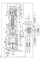
- FIG. 1 is a diagram showing an example of an injection molding machine management system according to the present embodiment.
- FIG. 1A is a side sectional view showing a state of the injection molding machine 1 at the time of mold opening
- FIG. 1B is a side sectional view showing a state of the injection molding machine 1 at the time of mold clamping.
- the X-axis, the Y-axis, and the Z-axis are perpendicular to each other, and the positive-negative direction of the X-axis (hereinafter, simply "X-direction") and the positive-negative direction of the Y-axis (hereinafter, simply "”.
- the "Y direction”) represents the horizontal direction
- the positive / negative direction of the Z axis hereinafter, simply "Z direction” represents the vertical direction.
- the management system SYS includes a plurality of (three in this example) injection molding machines 1 and a management device 2.
- the number of injection molding machines 1 included in the management system SYS may be one, two, or four or more.
- the injection molding machine 1 performs a series of operations for obtaining a molded product.
- the injection molding machine 1 is communicably connected to the management device 2 through a predetermined communication line NW, and data regarding the operating state of the injection molding machine 1 is connected to the management device 2 (an example of a predetermined external device) (hereinafter, "" Operation status data ") is sent (uploaded).
- the management device 2 (or its manager, worker, etc.) can grasp the operating state and manage the maintenance timing of the injection molding machine 1, the operation schedule of the injection molding machine 1, and the like.
- the communication line NW may include, for example, a mobile communication network having a base station as an end.
- the communication line NW may include, for example, a satellite communication network that uses a communication satellite.
- the communication line NW may include, for example, an Internet network.
- the communication line NW may include, for example, a LAN (Local Area Network) in the factory where the injection molding machine 1 is installed. Further, the communication line NW may be, for example, a short-range communication line corresponding to Bluetooth (registered trademark) communication, WiFi communication, or the like.
- LAN Local Area Network
- WiFi Wireless Fidelity
- the injection molding machine 1 includes a mold clamping device 100, an ejector device 200, an injection device 300, a moving device 400, and a controller 700.
- the mold clamping device 100 closes, molds, and opens the mold of the mold device 10.
- the mold clamping device 100 is, for example, a horizontal type, and the mold opening / closing direction is a horizontal direction.
- the mold clamping device 100 includes a fixed platen 110, a movable platen 120, a toggle support 130, a tie bar 140, a toggle mechanism 150, a mold clamping motor 160, a motion conversion mechanism 170, and a mold thickness adjusting mechanism 180.
- the moving direction of the movable platen 120 when the mold is closed (right direction in FIGS. 1A and 1B) is set to the front, and the moving direction of the movable platen 120 when the mold is opened (FIGS. 1A and 1B).
- the middle left direction will be described as the rear.
- the fixed platen 110 is fixed to the frame Fr.
- the fixed mold 11 is attached to the surface of the fixed platen 110 facing the movable platen 120.
- the movable platen 120 is movable in the mold opening / closing direction with respect to the frame Fr.
- a guide 101 for guiding the movable platen 120 is laid on the frame Fr.
- the movable mold 12 is attached to the surface of the movable platen 120 facing the fixed platen 110.
- the mold device 10 includes a fixed mold 11 corresponding to the fixed platen 110 and a movable mold 12 corresponding to the movable platen 120.
- the toggle support 130 is connected to the fixed platen 110 at a predetermined interval L, and is movably placed on the frame Fr in the mold opening / closing direction.
- the toggle support 130 may be movable along, for example, a guide laid on the frame Fr.
- the guide of the toggle support 130 may be common to the guide 101 of the movable platen 120.
- the fixed platen 110 is fixed to the frame Fr, and the toggle support 130 is movable in the mold opening / closing direction with respect to the frame Fr.
- the toggle support 130 is fixed to the frame Fr, and the fixed platen 110 is fixed to the frame Fr.
- it may be movable in the opening / closing direction.
- the tie bar 140 connects the fixed platen 110 and the toggle support 130 with an interval L in the mold opening / closing direction.
- a plurality of tie bars 140 may be used.
- Each tie bar 140 is parallel to the mold opening / closing direction and extends according to the mold clamping force.
- At least one tie bar 140 is provided with a tie bar distortion detector 141 that detects the distortion of the tie bar 140.
- the tie bar strain detector 141 is, for example, a strain gauge.
- the tie bar distortion detector 141 sends a signal indicating the detection result to the controller 700.
- the detection result of the tie bar strain detector 141 is used, for example, for detecting the mold clamping force.
- any mold clamping force detector that can be used to detect the mold clamping force may be used.
- the mold clamping force detector is not limited to the strain gauge type, and may be a piezoelectric type, a capacitance type, a hydraulic type, an electromagnetic type, or the like, and the mounting position thereof is not limited to the tie bar 140.
- the toggle mechanism 150 is arranged between the movable platen 120 and the toggle support 130, and moves the movable platen 120 with respect to the toggle support 130 in the mold opening / closing direction.
- the toggle mechanism 150 is composed of a crosshead 151, a pair of links, and the like.
- Each link group has a first link 152 and a second link 153 that are flexibly connected by a pin or the like.
- the first link 152 is swingably attached to the movable platen 120 with a pin or the like
- the second link 153 is swingably attached to the toggle support 130 with a pin or the like.
- the second link 153 is attached to the crosshead 151 via the third link 154.
- the configuration of the toggle mechanism 150 is not limited to the configurations shown in FIGS. 1A and 1B.
- the number of nodes in each link group is 5, but it may be 4, and one end of the third link 154 becomes a node between the first link 152 and the second link 153. May be combined.
- the mold clamping motor 160 is attached to the toggle support 130 and operates the toggle mechanism 150.
- the mold clamping motor 160 bends and stretches the first link 152 and the second link 153 by advancing and retreating the crosshead 151 with respect to the toggle support 130, and advances and retreats the movable platen 120 with respect to the toggle support 130.
- the mold clamping motor 160 is directly connected to the motion conversion mechanism 170, but may be connected to the motion conversion mechanism 170 via a belt, a pulley, or the like.
- the motion conversion mechanism 170 converts the rotational motion of the mold clamping motor 160 into a linear motion of the crosshead 151.
- the motion conversion mechanism 170 includes a screw shaft 171 and a screw nut 172 screwed onto the screw shaft 171.
- a ball or roller may be interposed between the screw shaft 171 and the screw nut 172.
- the mold clamping device 100 performs a mold closing process, a mold clamping process, a mold opening process, and the like under the control of the controller 700.
- the movable platen 120 is advanced by driving the mold clamping motor 160 to advance the crosshead 151 to the mold closing completion position at a set speed, and the movable mold 12 is touched by the fixed mold 11.
- the position and speed of the crosshead 151 are detected by using, for example, a mold clamping motor encoder 161 or the like.
- the mold clamping motor encoder 161 detects the rotation of the mold clamping motor 160 and sends a signal indicating the detection result to the controller 700.
- the crosshead position detector that detects the position of the crosshead 151 and the crosshead speed detector that detects the speed of the crosshead 151 are not limited to the mold clamping motor encoder 161 and general ones can be used. .. Further, the movable platen position detector that detects the position of the movable platen 120 and the movable platen speed detector that detects the speed of the movable platen 120 are not limited to the mold clamping motor encoder 161 and general ones can be used.
- the mold clamping force 160 is further driven to further advance the crosshead 151 from the mold closing completion position to the mold clamping position to generate a mold clamping force.
- a cavity space 14 is formed between the movable mold 12 and the fixed mold 11, and the injection device 300 fills the cavity space 14 with a liquid molding material.
- a molded product is obtained by solidifying the filled molding material.
- the number of cavity spaces 14 may be plural, in which case a plurality of molded articles can be obtained at the same time.
- the movable platen 120 is retracted and the movable mold 12 is separated from the fixed mold 11 by driving the mold clamping motor 160 and retracting the crosshead 151 to the mold opening completion position at a set speed. After that, the ejector device 200 projects the molded product from the movable mold 12.
- the setting conditions in the mold closing process and the mold clamping process are collectively set as a series of setting conditions.
- the speed and position of the crosshead 151 including the mold closing start position, the speed switching position, the mold closing completion position, and the mold clamping force
- the mold clamping force in the mold closing process and the mold clamping process are set as a series of setting conditions. Is set collectively as.
- the mold closing start position, speed switching position, mold closing completion position, and mold closing position are arranged in this order from the rear side to the front side, and represent the start point and the end point of the section in which the speed is set.
- the speed is set for each section.
- the speed switching position may be one or a plurality.
- the speed switching position does not have to be set. Only one of the mold clamping position and the mold clamping force may be set.
- the setting conditions in the mold opening process are set in the same way.
- the speed and position of the crosshead 151 in the mold opening step (including the mold opening start position, the speed switching position, and the mold opening completion position) are collectively set as a series of setting conditions.
- the mold opening start position, the speed switching position, and the mold opening completion position are arranged in this order from the front side to the rear side, and represent the start point and the end point of the section in which the speed is set.
- the speed is set for each section.
- the speed switching position may be one or a plurality.
- the speed switching position does not have to be set.
- the mold opening start position and the mold clamping position may be the same position.
- the mold opening completion position and the mold closing start position may be the same position.
- the speed, position, etc. of the movable platen 120 may be set instead of the speed, position, etc. of the crosshead 151.
- the mold clamping force may be set instead of the position of the crosshead (for example, the mold clamping position) or the position of the movable platen.
- the toggle mechanism 150 amplifies the driving force of the mold clamping motor 160 and transmits it to the movable platen 120.
- the amplification factor is also called the toggle magnification.
- the toggle magnification changes according to the angle (hereinafter, “link angle”) ⁇ formed by the first link 152 and the second link 153.
- the link angle ⁇ is obtained from the position of the crosshead 151. When the link angle ⁇ is 180 °, the toggle magnification is maximized.
- the mold thickness is adjusted so that a predetermined mold clamping force can be obtained at the time of mold clamping.
- the distance between the fixed platen 110 and the toggle support 130 is set so that the link angle ⁇ of the toggle mechanism 150 becomes a predetermined angle at the time of the mold touch when the movable mold 12 touches the fixed mold 11. Adjust L.
- the mold clamping device 100 has a mold thickness adjusting mechanism 180 that adjusts the mold thickness by adjusting the distance L between the fixed platen 110 and the toggle support 130.
- the mold thickness adjusting mechanism 180 rotates the screw shaft 181 formed at the rear end of the tie bar 140, the screw nut 182 rotatably held by the toggle support 130, and the screw nut 182 screwed to the screw shaft 181. It has a mold thickness adjusting motor 183.
- the screw shaft 181 and the screw nut 182 are provided for each tie bar 140.
- the rotation of the mold thickness adjusting motor 183 may be transmitted to the plurality of screw nuts 182 via the rotation transmission unit 185.
- a plurality of screw nuts 182 can be rotated in synchronization.
- the rotation transmission unit 185 is composed of, for example, gears and the like.
- a passive gear is formed on the outer circumference of each screw nut 182
- a drive gear is attached to the output shaft of the mold thickness adjusting motor 183
- a plurality of passive gears and an intermediate gear that meshes with the drive gear are located at the center of the toggle support 130. It is held rotatably.
- the rotation transmission unit 185 may be composed of a belt, a pulley, or the like instead of the gear.
- the operation of the mold thickness adjusting mechanism 180 is controlled by the controller 700.
- the controller 700 drives the mold thickness adjusting motor 183 to rotate the screw nut 182 to adjust the position of the toggle support 130 that holds the screw nut 182 rotatably with respect to the fixed platen 110, and the fixed platen 110 and the toggle. Adjust the distance L from the support 130.
- the interval L is detected using the mold thickness adjustment motor encoder 184.
- the mold thickness adjusting motor encoder 184 detects the rotation amount and the rotation direction of the mold thickness adjusting motor 183, and sends a signal indicating the detection result to the controller 700.
- the detection result of the mold thickness adjustment motor encoder 184 is used for monitoring and controlling the position and interval L of the toggle support 130.
- the toggle support position detector that detects the position of the toggle support 130 and the interval detector that detects the interval L are not limited to the mold thickness adjustment motor encoder 184, and general ones can be used.
- the mold thickness adjusting mechanism 180 adjusts the interval L by rotating one of the screw shaft 181 and the screw nut 182 that are screwed together.
- a plurality of mold thickness adjusting mechanisms 180 may be used, and a plurality of mold thickness adjusting motors 183 may be used.
- the mold clamping device 100 of the present embodiment is a horizontal type in which the mold opening / closing direction is horizontal, but may be a vertical type in which the mold opening / closing direction is vertical.
- the mold clamping device 100 of the present embodiment has a mold clamping motor 160 as a drive source, a hydraulic cylinder may be provided instead of the mold clamping motor 160. Further, the mold clamping device 100 may have a linear motor for opening and closing the mold and an electromagnet for mold clamping.
- the ejector device 200 projects a molded product from the mold device 10.
- the ejector device 200 includes an ejector motor 210, a motion conversion mechanism 220, an ejector rod 230, and the like.
- the moving direction of the movable platen 120 when the mold is closed (the right direction in FIGS. 1A and 1B) is set to the front, and the movable platen 120 when the mold is opened.
- the moving direction of the above (the left direction in FIGS. 1A and 1B) will be described as the rear.
- the ejector motor 210 is attached to the movable platen 120.
- the ejector motor 210 is directly connected to the motion conversion mechanism 220, but may be connected to the motion conversion mechanism 220 via a belt, a pulley, or the like.
- the motion conversion mechanism 220 converts the rotational motion of the ejector motor 210 into the linear motion of the ejector rod 230.
- the motion conversion mechanism 220 includes a screw shaft and a screw nut screwed onto the screw shaft.
- a ball or roller may be interposed between the screw shaft and the screw nut.
- the ejector rod 230 can be moved forward and backward in the through hole of the movable platen 120.
- the front end portion of the ejector rod 230 comes into contact with the movable member 15 which is movably arranged inside the movable mold 12.
- the front end portion of the ejector rod 230 may or may not be connected to the movable member 15.
- the ejector device 200 performs the ejection process under the control of the controller 700.
- the ejector motor 210 is driven to advance the ejector rod 230 from the standby position to the ejection position at a set speed, thereby advancing the movable member 15 and projecting the molded product. After that, the ejector motor 210 is driven to retract the ejector rod 230 at a set speed, and the movable member 15 is retracted to the original standby position.
- the position and speed of the ejector rod 230 are detected by using, for example, the ejector motor encoder 211.
- the ejector motor encoder 211 detects the rotation of the ejector motor 210 and sends a signal indicating the detection result to the controller 700.
- the ejector rod position detector that detects the position of the ejector rod 230 and the ejector rod speed detector that detects the speed of the ejector rod 230 are not limited to the ejector motor encoder 211, and general ones can be used.
- the injection device 300 is installed on a slide base 301 that can move forward and backward with respect to the frame Fr, and can move forward and backward with respect to the mold device 10.
- the injection device 300 touches the mold device 10 to fill the cavity space 14 in the mold device 10 with a molding material.
- the injection device 300 includes, for example, a cylinder 310, a nozzle 320, a screw 330, a weighing motor 340, an injection motor 350, a pressure detector 360, and the like.
- the direction in which the injection device 300 is brought closer to the mold device 10 is the forward direction
- the direction in which the injection device 300 is separated from the mold device 10 is the direction in which the injection device 300 is separated from the mold device 10.
- the right direction in FIGS. 1A and 1B will be described as the rear.
- the cylinder 310 heats the molding material supplied internally from the supply port 311.
- the molding material includes, for example, a resin or the like.
- the molding material is formed into, for example, pellets and is supplied to the supply port 311 in a solid state.
- the supply port 311 is formed at the rear of the cylinder 310.
- a cooler 312 such as a water-cooled cylinder is provided on the outer periphery of the rear portion of the cylinder 310.
- a heater 313 such as a band heater and a temperature detector 314 are provided on the outer periphery of the cylinder 310 in front of the cooler 312.
- the cylinder 310 is divided into a plurality of zones in the axial direction of the cylinder 310 (left-right direction in FIGS. 1A and 1B).
- a heater 313 and a temperature detector 314 are provided in each zone.
- the controller 700 controls the heater 313 so that the detection temperature of the temperature detector 314 reaches the set temperature.
- the nozzle 320 is provided at the front end of the cylinder 310 and is pressed against the mold device 10.
- a heater 313 and a temperature detector 314 are provided on the outer periphery of the nozzle 320.
- the controller 700 controls the heater 313 so that the detected temperature of the nozzle 320 reaches the set temperature.
- the screw 330 is arranged in the cylinder 310 so as to be rotatable and retractable.
- the molding material is fed forward along the spiral groove of the screw 330.
- the molding material is gradually melted by the heat from the cylinder 310 while being fed forward.
- the screw 330 is retracted. After that, when the screw 330 is advanced, the liquid molding material accumulated in front of the screw 330 is ejected from the nozzle 320 and filled in the mold apparatus 10.
- a backflow prevention ring 331 is freely attached to the front part of the screw 330 as a backflow prevention valve for preventing the backflow of the molding material from the front to the rear of the screw 330 when the screw 330 is pushed forward.
- the backflow prevention ring 331 When the screw 330 is advanced, the backflow prevention ring 331 is pushed backward by the pressure of the molding material in front of the screw 330, and is relative to the screw 330 up to a closing position (see FIG. 1B) that blocks the flow path of the molding material. fall back. As a result, the molding material accumulated in the front of the screw 330 is prevented from flowing backward.
- the backflow prevention ring 331 is pushed forward by the pressure of the molding material sent forward along the spiral groove of the screw 330, and the opening position opens the flow path of the molding material. (See FIG. 1A) advances relative to the screw 330. As a result, the molding material is sent to the front of the screw 330.
- the backflow prevention ring 331 may be either a co-rotating type that rotates with the screw 330 or a non-co-rotating type that does not rotate with the screw 330.
- the injection device 300 may have a drive source for moving the backflow prevention ring 331 forward and backward between the open position and the closed position with respect to the screw 330.
- the weighing motor 340 rotates the screw 330.
- the drive source for rotating the screw 330 is not limited to the metering motor 340, and may be, for example, a hydraulic pump or the like.
- the injection motor 350 advances and retreats the screw 330.
- a motion conversion mechanism or the like for converting the rotational motion of the injection motor 350 into the linear motion of the screw 330 is provided.
- the motion conversion mechanism has, for example, a screw shaft and a screw nut screwed onto the screw shaft.
- a ball, a roller, or the like may be provided between the screw shaft and the screw nut.
- the drive source for advancing and retreating the screw 330 is not limited to the injection motor 350, and may be, for example, a hydraulic cylinder or the like.
- the pressure detector 360 detects the pressure transmitted between the injection motor 350 and the screw 330.
- the pressure detector 360 is provided in the force transmission path between the injection motor 350 and the screw 330 to detect the pressure acting on the pressure detector 360.
- the pressure detector 360 sends a signal indicating the detection result to the controller 700.
- the detection result of the pressure detector 360 is used for controlling and monitoring the pressure received by the screw 330 from the molding material, the back pressure on the screw 330, the pressure acting on the molding material from the screw 330, and the like.
- the injection device 300 performs a weighing process, a filling process, a pressure holding process, and the like under the control of the controller 700.
- the weighing motor 340 is driven to rotate the screw 330 at a set rotation speed, and the molding material is sent forward along the spiral groove of the screw 330. Along with this, the molding material is gradually melted. As the liquid molding material is fed forward of the screw 330 and accumulated in the front of the cylinder 310, the screw 330 is retracted.
- the rotation speed of the screw 330 is detected by using, for example, a metering motor encoder 341.
- the metering motor encoder 341 detects the rotation of the metering motor 340 and sends a signal indicating the detection result to the controller 700.
- the screw rotation speed detector that detects the rotation speed of the screw 330 is not limited to the metering motor encoder 341, and a general screw can be used.
- the injection motor 350 may be driven to apply a set back pressure to the screw 330 in order to limit the sudden retreat of the screw 330.
- the back pressure on the screw 330 is detected using, for example, a pressure detector 360.
- the pressure detector 360 sends a signal indicating the detection result to the controller 700.
- the injection motor 350 is driven to advance the screw 330 at a set speed, and the liquid molding material accumulated in front of the screw 330 is filled in the cavity space 14 in the mold apparatus 10.
- the position and speed of the screw 330 are detected using, for example, an injection motor encoder 351.
- the injection motor encoder 351 detects the rotation of the injection motor 350 and sends a signal indicating the detection result to the controller 700.
- V / P switching switching from the filling process to the pressure holding process
- the position where V / P switching is performed is also referred to as a V / P switching position.
- the set speed of the screw 330 may be changed according to the position and time of the screw 330.
- the screw 330 may be temporarily stopped at the set position, and then V / P switching may be performed. Immediately before the V / P switching, instead of stopping the screw 330, the screw 330 may be moved forward or backward at a slow speed.
- the screw position detector for detecting the position of the screw 330 and the screw speed detector for detecting the speed of the screw 330 are not limited to the injection motor encoder 351 and general ones can be used.
- the injection motor 350 is driven to push the screw 330 forward, and the pressure of the molding material (hereinafter, also referred to as “holding pressure”) at the front end of the screw 330 is maintained at a set pressure in the cylinder 310.
- the remaining molding material is pushed toward the mold device 10.
- the shortage of molding material due to cooling shrinkage in the mold apparatus 10 can be replenished.
- the holding pressure is detected using, for example, a pressure detector 360.
- the pressure detector 360 sends a signal indicating the detection result to the controller 700.
- the set value of the holding pressure may be changed according to the elapsed time from the start of the holding pressure step and the like.
- the molding material in the cavity space 14 in the mold apparatus 10 is gradually cooled, and when the pressure holding process is completed, the inlet of the cavity space 14 is closed with the solidified molding material. This state is called a gate seal, and the backflow of the molding material from the cavity space 14 is prevented.
- the cooling step is started. In the cooling step, the molding material in the cavity space 14 is solidified. A weighing step may be performed during the cooling step to reduce the molding cycle time.
- the injection device 300 of the present embodiment is an in-line screw type, but may be a pre-plastic type or the like.
- the pre-plastic injection device supplies the molded material melted in the plasticized cylinder to the injection cylinder, and injects the molding material from the injection cylinder into the mold device.
- a screw is rotatably or rotatably arranged in the plasticized cylinder so as to be able to advance and retreat, and a plunger is rotatably arranged in the injection cylinder.
- the injection device 300 of the present embodiment is a horizontal type in which the axial direction of the cylinder 310 is horizontal, but may be a vertical type in which the axial direction of the cylinder 310 is in the vertical direction.
- the mold clamping device combined with the vertical injection device 300 may be vertical or horizontal.
- the mold clamping device combined with the horizontal injection device 300 may be horizontal or vertical.
- the moving device 400 advances and retreats the injection device 300 with respect to the mold device 10. Further, the moving device 400 presses the nozzle 320 against the mold device 10 to generate a nozzle touch pressure.
- the moving device 400 includes a hydraulic pump 410, a motor 420 as a drive source, a hydraulic cylinder 430 as a hydraulic actuator, and the like.
- the direction in which the injection device 300 approaches the mold device 10 is the front, and the injection device 300 is the gold.
- the direction in which the mold device 10 is separated from the mold device 10 (right direction in FIGS. 1A and 1B) will be described as the rear.
- the moving device 400 is arranged on one side of the cylinder 310 of the injection device 300 in FIGS. 1A and 1B, the moving device 400 may be arranged on both sides of the cylinder 310 or may be arranged symmetrically with respect to the cylinder 310.
- the hydraulic pump 410 has a first port 411 and a second port 412.
- the hydraulic pump 410 is a pump that can rotate in both directions, and by switching the rotation direction of the motor 420, the hydraulic fluid (for example, oil) is sucked from one of the first port 411 and the second port 412, and the hydraulic fluid (for example, oil) is sucked from the other. Discharge to generate hydraulic pressure. Further, the hydraulic pump 410 can also suck the hydraulic fluid from the tank and discharge the hydraulic fluid from either the first port 411 or the second port 412.
- the motor 420 operates the hydraulic pump 410.
- the motor 420 drives the hydraulic pump 410 in the rotational direction and rotational torque according to the control signal from the controller 700.
- the motor 420 may be an electric motor or an electric servomotor.
- the hydraulic cylinder 430 has a cylinder body 431, a piston 432, and a piston rod 433.
- the cylinder body 431 is fixed to the injection device 300.
- the piston 432 divides the inside of the cylinder body 431 into a front chamber 435 as a first chamber and a rear chamber 436 as a second chamber.
- the piston rod 433 is fixed to the fixed platen 110.
- the front chamber 435 of the hydraulic cylinder 430 is connected to the first port 411 of the hydraulic pump 410 via the first flow path 401.
- the hydraulic fluid discharged from the first port 411 is supplied to the front chamber 435 via the first flow path 401, so that the injection device 300 is pushed forward.
- the injection device 300 is advanced and the nozzle 320 is pressed against the fixed mold 11.
- the anterior chamber 435 functions as a pressure chamber that generates a nozzle touch pressure of the nozzle 320 by the pressure of the hydraulic fluid supplied from the hydraulic pump 410.
- the rear chamber 436 of the hydraulic cylinder 430 is connected to the second port 412 of the hydraulic pump 410 via the second flow path 402.
- the hydraulic fluid discharged from the second port 412 is supplied to the rear chamber 436 of the hydraulic cylinder 430 via the second flow path 402, so that the injection device 300 is pushed backward.
- the injection device 300 is retracted and the nozzle 320 is separated from the fixed mold 11.
- the mobile device 400 is not limited to the configuration including the hydraulic cylinder 430.
- an electric motor and a motion conversion mechanism that converts the rotational motion of the electric motor into a linear motion of the injection device 300 may be used.
- the controller 700 directly transmits a control signal to the mold clamping device 100, the ejector device 200, the injection device 300, the moving device 400, and the like to control the drive of the injection molding machine 1.
- the controller 700 is mainly composed of a computer having, for example, a CPU (Central Processing Unit) 701, a memory device 702, an auxiliary storage device 703, and an input / output interface device 704.
- the controller 700 performs various controls by causing the CPU 701 to execute a program installed in the auxiliary storage device 703. Further, the controller 700 receives an external signal or outputs a signal to the outside through the interface device 704.
- a CPU Central Processing Unit
- controller 700 may be shared by a plurality of controllers.
- the controller 700 repeatedly manufactures a molded product by causing the injection molding machine 1 to repeatedly perform a mold closing step, a mold clamping step, a mold opening step, and the like. Further, the controller 700 causes the injection device 300 to perform a weighing step, a filling step, a pressure holding step, and the like during the mold clamping step.
- a series of operations for obtaining a molded product for example, an operation from the start of the weighing process by the injection device 300 to the start of the weighing process by the next injection device 300 is also referred to as a "shot” or a “molding cycle”.
- the time required for one shot is also referred to as “molding cycle time”.
- One molding cycle is composed of, for example, a weighing process, a mold closing process, a mold clamping process, a filling process, a pressure holding process, a cooling process, a mold opening process, and a protrusion process in this order.
- This order is the starting order of each step.
- the filling step, the pressure holding step, and the cooling step are performed between the start of the mold clamping step and the end of the mold clamping step. Further, the end of the mold clamping process coincides with the start of the mold opening process.
- the weighing step may be performed during the cooling step of the previous molding cycle, in which case the mold closing step may be performed at the beginning of the molding cycle.
- the filling step may be started during the mold closing step.
- the ejection step may be started during the mold opening step.
- the mold opening step may be started during the weighing step. This is because even if the mold opening process is started during the weighing process, the molding material does not leak from the nozzle 320 if the on-off valve closes the flow path of the nozzle 320.
- the controller 700 is connected to the operation device 750, the display device 760, and the like.
- the operation device 750 receives an operation input related to the injection molding machine 1 by the user, and outputs a signal corresponding to the operation input to the controller 700.
- the display device 760 displays various images under the control of the controller 700.
- the display device 760 displays, for example, an operation screen related to the injection molding machine 1 in response to an operation input in the operation device 750.
- the operation screen displayed on the display device 760 is used for setting related to the injection molding machine 1.
- the setting relating to the injection molding machine 1 includes, for example, setting of molding conditions (specifically, inputting a set value) relating to the injection molding machine 1. Further, the setting includes, for example, a setting related to selection of a type of detection value of various sensors and the like related to the injection molding machine 1 recorded as logging data at the time of molding operation. Further, in the setting, for example, display specifications (for example, the type of actual value to be displayed and how to display it) on the display device 760 of the detected value (actual value) of various sensors related to the injection molding machine 1 during the molding operation. Etc.) settings are included.
- a plurality of operation screens are prepared and may be displayed by switching to the display device 760 or may be displayed in an overlapping manner.
- the user can make settings (including input of set values) related to the injection molding machine 1 by operating the operation device 750 while looking at the operation screen displayed on the display device 760.
- the display device 760 displays, for example, an information screen that provides the user with various information according to the operation on the operation screen under the control of the controller 700.
- a plurality of information screens are prepared and may be displayed by switching to the display device 760 or may be displayed in an overlapping manner.
- the display device 760 displays the setting contents regarding the injection molding machine 1 (for example, the setting contents regarding the molding conditions of the injection molding machine 1).
- the display device 760 displays management information (for example, information regarding the operation record of the injection molding machine 1).
- the operation device 750 and the display device 760 may be configured as, for example, a touch panel type display and integrated.
- operation device 750 and the display device 760 of the present embodiment are integrated, they may be provided independently. Further, a plurality of operating devices 750 may be provided.
- the management device 2 is communicably connected to the injection molding machine 1 through the communication line NW.
- the management device 2 is, for example, a computer (for example, a cloud server) installed in a remote location such as a management center outside the factory where the injection molding machine 1 is installed. Further, the management device 2 may be, for example, an edge server installed in a place relatively close to the factory where the injection molding machine 1 is installed (for example, a radio base station or a station building near the factory). .. Further, the management device 2 may be a computer terminal in the factory where the injection molding machine 1 is installed. Further, the management device 2 may be a mobile terminal (for example, a smartphone, a tablet terminal, a laptop computer terminal, etc.) that can be carried by the administrator of the injection molding machine 1.
- a computer for example, a cloud server
- the management device 2 may be, for example, an edge server installed in a place relatively close to the factory where the injection molding machine 1 is installed (for example, a radio base station or a station building near the factory). ..
- the management device 2 may be a computer terminal in the factory where the injection
- the management device 2 can grasp the operating state of the injection molding machine 1 and manage the operating state of the injection molding machine 1 based on the data uploaded from the injection molding machine 1, for example. Further, the management device 2 can perform various diagnoses such as an abnormality diagnosis of the injection molding machine 1 based on the grasped operating state of the injection molding machine 1.
- the management device 2 can transmit control information (for example, information on various setting conditions) to the injection molding machine 1 through the communication line NW, for example.
- control information for example, information on various setting conditions
- the management device 2 is, for example, a control command for causing the plurality of injection molding machines 1 to perform the same operation while grasping the operating status of the plurality of injection molding machines 1 from the data uploaded from the plurality of injection molding machines 1. Can be transmitted to synchronize the operations of the plurality of injection molding machines 1.
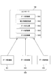
- FIG. 2 is a diagram showing an example of a configuration related to data collection of the injection molding machine 1.
- the injection molding machine 1 includes a controller 700 and a data acquisition unit 800 as a configuration related to data collection.
- the controller 700 is communicably connected through a predetermined communication line (for example, a local network such as Ethernet (registered trademark)) configured inside the injection molding machine 1.
- the controller 700 includes a data receiving unit 7001, a data processing unit 7003, and a data transmitting unit 7005 as functional units realized by executing a program installed in the auxiliary storage device 703 on the CPU 701. Further, the controller 700 uses the correction information storage unit 7002, the data storage unit 7004, and the like.
- the correction information storage unit 7002, the data storage unit 7004, and the like can be realized by an auxiliary storage device 703 inside the controller 700, an external storage device communicably connected to the controller 700, and the like.
- the data receiving unit 7001 receives the data transmitted from the data acquisition unit 800 through a predetermined communication line.
- the function related to data collection of the controller 700 is activated every relatively long cycle (hereinafter, "data collection cycle") (an example of the first cycle) to collect data. Therefore, the data receiving unit 7001 receives the latest data among the data periodically transmitted from the data acquisition unit 800 for each data acquisition cycle.
- the data collection cycle is, for example, 1 ms.
- the correction information storage unit 7002 stores information (hereinafter, "correction information") for performing processing (correction) for compensating for the time-series relationship of the data received by the data reception unit 7001.
- the data processing unit 7003 processes (corrects) the acquisition timing of the data received by the data receiving unit 7001 or the content of the data based on the correction information of the correction information storage unit 7002.
- the data processing unit 7003 outputs data and information representing the acquisition timing of the data (hereinafter, “acquisition timing information”).
- the data storage unit 7004 stores the data output from the data processing unit 7003 and the acquisition timing information corresponding to the data.
- the data output from the data processing unit 7003 may be different from the data received by the data receiving unit 7001, or may remain the data received by the data receiving unit 7001. This is because, as will be described later, it may not be necessary to process (correct) the data received by the data receiving unit 7001.
- the data transmission unit 7005 transmits (uploads) the data stored in the data storage unit 7004 and the acquisition timing information of the data to the management device 2 at a predetermined timing.
- the management device 2 When the management device 2 recognizes the data acquisition cycle of the data receiving unit 7001 and the respective data acquisition cycles of the data acquisition units 801 to 803, and the data processing unit 7003 processes the data contents. , Transmission of acquisition timing information may be omitted.
- the data acquisition unit 800 includes a plurality of data acquisition units (in this example, three data acquisition units 801 to 803).
- the number of data acquisition units included in the data acquisition unit 800 may be arbitrary.
- the data acquisition unit 800 may be composed of only one data acquisition unit. That is, the controller 700 may be configured to collect (receive) data from only one data acquisition unit 800.
- the data acquisition unit 800 may be configured to include only two data acquisition units. That is, any one of the data acquisition units 801 to 803 may be omitted.
- the data acquisition unit 800 may be configured to include four or more data acquisition units.
- the data acquisition units 801 to 803 acquire different types of operating status data. Further, the data acquisition units 801 to 803 may acquire, for example, operation input data (hereinafter, “operation input data”) relating to injection molding machines 1 that are different from each other.
- the operation input data may include operation input data received by the operation device 750. Further, the operation input data may include external operation input input (received) from the management device 2 or the like, that is, operation input data related to remote control.
- operation input data may include operation input data received by the operation device 750.
- the operation input data may include external operation input input (received) from the management device 2 or the like, that is, operation input data related to remote control.
- the case where the operating state data is acquired by the data acquisition units 801 to 803 will be mainly described, but the same contents will be described in the data acquisition unit 801 in place of or in addition to the operating state data. The same applies to the case of acquisition by ⁇ 803.
- the data acquisition units 801 to 803 may acquire, for example, the operating state data of the driven unit of the injection molding machine 1.
- the data acquisition units 801 to 803 are, for example, a drive device (for example, driving an electric actuator) that outputs data regarding the operating state of the actuator that drives the driven unit of the injection molding machine 1 as operating state data. Circuits, etc.) may be included.
- the data acquisition units 801 to 803 are, for example, a detection device (for example, the position and speed of the driven unit) that outputs detection data corresponding to the operating state of the driven unit of the injection molding machine 1 as operating state data. A detector to detect) may be included.
- the driven portion of the injection molding machine 1 includes, for example, the toggle mechanism 150 and the mold thickness adjusting mechanism 180 of the mold clamping device 100, the motion conversion mechanism 220 of the ejector device 200, the screw 330 and the backflow prevention ring 331 of the injection device 300, and the backflow prevention ring 331.
- the hydraulic pump 410 of the moving device 400 and the like are included.
- the actuators include, for example, the mold clamping motor 160 and the mold thickness adjusting motor 183 of the mold clamping device 100, the ejector motor 210 of the ejector device 200, the weighing motor 340 and the injection motor 350 of the injection device 300, and the motor of the moving device 400. 420 etc. are included.
- the detection devices include, for example, the mold clamping motor encoder 161 and the mold thickness adjusting motor encoder 184 of the mold clamping device 100, the ejector motor encoder 211 of the ejector device 200, the weighing motor encoder 341 of the injection device 300, and the injection motor encoder 351. And the pressure detector 360 and the like.
- the data acquisition units 801 to 803 may acquire, for example, the operating state data of the heated unit of the injection molding machine 1.
- the data acquisition units 801 to 803 are, for example, a drive device (for example, an electric type) that outputs data on the operating state of the heating device that heats the heated portion of the injection molding machine 1 as operating state data.
- the drive circuit of the heater, etc. may be included.
- the data acquisition units 801 to 803 are, for example, a detection device (for example, the temperature state of the heated part) that outputs detection data regarding the heated state (temperature state) of the heated part of the injection molding machine 1 as operating state data.
- a detector may be included.
- the heated portion of the injection molding machine 1 includes, for example, the cylinder 310 (outer circumference) of the injection device 300. Further, the heating device includes a heater 313 of the injection device 300 and the like. Further, the detection device includes the temperature detector 314 of the injection device 300 and the like.
- the data acquisition units 801 to 803 are lower-level controllers (hereinafter, “lower-level”) that operate under the control of the upper-level controller 700 (an example of the upper-level controller). Controller ") may be included.
- the lower controller may acquire (receive) the operating state data from the drive device or the detection device under its control, and transmit it to the upper controller 700, for example.
- the lower controller may acquire, for example, information regarding a control command of the injection molding machine 1 generated by itself (hereinafter, “control information”) and transmit it to the upper controller 700.
- the data acquisition units 801 to 803 acquire the operating state data of the injection molding machine 1 and transmit it to the controller 700 at each predetermined cycle (hereinafter, “data acquisition cycle”) (an example of the second cycle). ..
- the data acquisition units 801 to 803 may all have the same data acquisition cycle, or some or all of the data acquisition cycles may be different.
- the required control performance (accuracy) differs for each driven unit and heated unit corresponding to the data acquired by each of the data acquisition units 801 to 803, and the required accuracy is high. This is because the data acquisition cycle of the operating state data related to the heating unit is relatively short.
- FIG. 3 is a timing chart showing a first example of the operation of the controller 700 and the data acquisition units 801 to 803.
- FIG. 3 shows a timing chart 30 showing the operation of the controller 700, a timing chart 31 showing the operation of the data acquisition unit 801, a timing chart 32 showing the operation of the data acquisition unit 802, and a timing chart showing the operation of the data acquisition unit 803. 33 is included.
- FIG. 4A and 4B are diagrams illustrating a first example of a method of compensating for the time-series relationship of data received by the controller 700.
- FIG. 4A is a diagram showing a first example of correction information
- FIG. 4B is a diagram showing a first example of a data processing (correction) method based on the correction information.
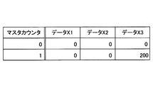
- the data (types) acquired by the data acquisition units 801 to 803 are represented by the data X1 to X3, respectively, and the data X1 to X3 at the time t are represented by the data X1 (t) to the data X3 (t). Each is represented.
- the master counter in the figure is counted up by "1" every time the data collection function (data receiving unit 7001 or the like) of the controller 700 is activated by an interrupt, with the initial value set to "0".
- data collection function data receiving unit 7001 or the like
- the data receiving unit 7001 receives the data X1 to X3 most recently output (transmitted) from the data acquisition units 801 to 803 every 1000 ⁇ sec.
- the data acquisition units 801 to 803 acquire data at different data acquisition cycles. Specifically, the data acquisition unit 801 acquires the data X1 every 100 ⁇ sec and outputs (transmits) it to the outside (controller 700). The data acquisition unit 802 acquires data X2 every 200 ⁇ sec and outputs (transmits) it to the outside (controller 700). The data acquisition unit 803 acquires the data X3 every 400 ⁇ sec and outputs (transmits) it to the outside (controller 700).
- the controller 700 transmits a trigger signal instructing the start of data acquisition to the data acquisition units 801 to 803. As a result, the data acquisition units 801 to 803 start the data acquisition cycle at substantially the same timing. Therefore, the controller 700 can match the timing of starting data acquisition of the data acquisition units 801 to 803.
- the data acquisition cycle (1000 ⁇ sec) of the controller 700 is divisible by the respective data acquisition cycles (100 ⁇ sec, 200 ⁇ sec) of the data acquisition units 801, 802. Therefore, the acquisition timing of the data X1 and X2 by the data acquisition units 801, 802 and the reception timing of the data X1 and X2 by the controller 700 (data reception unit 7001) substantially coincide with each other.
- the data acquisition cycle (1000 ⁇ sec) of the controller 700 is not divisible by the data acquisition cycle (400 ⁇ sec) of the data acquisition unit 803. Therefore, the reception timing of the data X3 by the controller 700 (data receiving unit 7001) is delayed by 200 ⁇ sec with respect to the acquisition timing of the data X3 by the data acquisition unit 803 at a frequency of once every two times. Therefore, the controller 700 can grasp in advance the relationship of the delay amount of the data reception timing by the controller 700 with respect to the acquisition timing of the data X1 to X3 by the data acquisition units 801 to 803 as correction information.
- the correction information includes the amount of delay in the reception timing by the controller 700 with respect to the respective acquisition timings of the data X1 to X3 when the master counter is "0" and "1". Is regulated. Further, the case where the master counter is "2" or more is omitted. This is because when the master counter is "2" or later, the state of the delay amount when the master counter is "0" and the state of the delay amount when the master counter is "1" are repeated.
- the controller 700 corrects the acquisition timing (acquisition time) of the data X1 to X3 by subtracting the delay amount defined by the correction information from the reception time based on the correction information of FIG. 4A. Can be done.
- the controller 700 data processing unit 7003 sets the acquisition timing of the data X3 acquired (received) at the time "1000" ⁇ sec to "800” by subtracting the delay amount "200" ⁇ sec from the time "1000" ⁇ sec. Correct to ⁇ sec.
- the controller 700 can correct the timing (reception time) of the data X3 acquired by the controller 700 to the timing when the data X3 is acquired by the data acquisition unit 803.
- the controller 700 processes (corrects) the acquisition timing of the data X3 so that the data X1 to X3 can be compared in time series, and when the data X3 is received from the data acquisition unit 803 for each data collection cycle.
- the series relationship can be compensated.
- controller 700 may use the received data X3 to extrapolate the data X3 at the reception time.
- the data X3 at the reception times "1000" ⁇ sec and "3000" ⁇ sec may be extrapolated by the following equations (1) and (2).
- X3 (1000) X3 (800) ⁇ 1000/800 ⁇ ⁇ ⁇ (1)
- X3 (3000) X3 (2800) ⁇ 1000/800 ⁇ ⁇ ⁇ (2)
- the controller 700 processes (corrects) the contents of the data X3 so that the data X1 to X3 can be compared in time series, and the data X3 received from the data acquisition unit 803 for each data collection cycle. Time series relationships can be compensated.
- the controller 700 uses the amount of deviation (delay amount) in the acquisition timing of the data X3 by the data acquisition unit 803 with respect to the data acquisition timing, and uses the amount of deviation (delay amount) in the acquisition timing of the collected (received) data and the contents of the data. Can be corrected. Therefore, the controller 700 compensates for the time-series relationship of the data X3 acquired by the data acquisition unit 803, and transmits the data X1 to X3 to the management device 2 in a state where the data X1 to X3 can be compared in the time series. be able to.
- FIG. 5 is a timing chart showing a second example of the operation of the controller 700 and the data acquisition units 801 to 803.
- FIG. 5 shows a timing chart 50 showing the operation of the controller 700, a timing chart 51 showing the operation of the data acquisition unit 801, a timing chart 52 showing the operation of the data acquisition unit 802, and a timing chart showing the operation of the data acquisition unit 803. 53 is included.
- FIG. 6A and 6B are diagrams illustrating a second example of a method of compensating for the time series relationship of the data received by the controller 700. Specifically, FIG. 6A is a diagram showing a second example of correction information, and FIG. 6B is a diagram showing a second example of a data processing (correction) method based on the correction information.
- the data receiving unit 7001 receives the data X1 to X3 most recently output (transmitted) from the data acquisition units 801 to 803 every 1000 ⁇ sec.
- the data acquisition units 801 to 803 acquire data in different data acquisition cycles as in the case of the first example described above. Specifically, the data acquisition unit 801 acquires the data X1 every 100 ⁇ sec and outputs (transmits) it to the outside (controller 700), as in the case of the first example described above. The data acquisition unit 802 acquires data X2 every 300 ⁇ sec and outputs (transmits) it to the outside (controller 700). The data acquisition unit 803 acquires the data X3 every 400 ⁇ sec and outputs (transmits) it to the outside (controller 700).
- the controller 700 transmits a trigger signal instructing the start of data acquisition to the data acquisition units 801 to 803 as in the case of the first example described above.
- the data acquisition units 801 to 803 start the data acquisition cycle at substantially the same timing. Therefore, the controller 700 can match the timing of starting data acquisition of the data acquisition units 801 to 803.
- the data acquisition cycle (1000 ⁇ sec) of the controller 700 is divisible by the data acquisition cycle (100 ⁇ sec) of the data acquisition unit 801. Therefore, the acquisition timing of the data X1 by the data acquisition unit 801 and the reception timing of the data X1 by the controller 700 (data reception unit 7001) substantially coincide with each other.
- the data acquisition cycle (1000 ⁇ sec) of the controller 700 is not divisible by the respective data acquisition cycles (300 ⁇ sec, 400 ⁇ sec) of the data acquisition units 802 and 803. Therefore, the reception timing of the data X2 by the controller 700 (data receiving unit 7001) is delayed by 100 ⁇ sec or 200 ⁇ sec from the acquisition timing of the data X2 by the data acquisition unit 802 at a frequency of twice every three times. Further, as in the case of the first example described above, the reception timing of the data X3 by the controller 700 (data receiving unit 7001) is delayed by 200 ⁇ sec from the acquisition timing of the data X3 by the data acquisition unit 803 at a frequency of once every two times. .. Therefore, the controller 700 can grasp in advance the relationship of the delay amount of the data reception timing by the controller 700 with respect to the acquisition timing of the data X1 to X3 by the data acquisition units 801 to 803 as correction information.
- the correction information includes the amount of delay in the reception timing by the controller 700 with respect to the respective acquisition timings of the data X1 to X3 when the master counter is "0" to "5". Is regulated. Further, the case where the master counter is "6" or more is omitted. This is because when the master counter is "6" or later, the delay amount states when the master counter is "0" to "5" are repeated in the same order.
- the controller 700 corrects the acquisition timing (acquisition time) of the data X1 to X3 by subtracting the delay amount defined by the correction information from the reception time based on the correction information of FIG. 6A. Can be done.
- the controller 700 data processing unit 7003 sets the acquisition timing of the data X2 acquired (received) at the time "1000" ⁇ sec by subtracting the delay amount "100" ⁇ sec from the time "1000" ⁇ sec to "900". Correct to ⁇ sec.
- the controller 700 corrects the acquisition timing of the data X2 acquired (received) at the time “2000" ⁇ sec to "1800" ⁇ sec by subtracting the delay amount "200" ⁇ sec from the time "2000" ⁇ sec. Further, the controller 700 also corrects the data X3 in the same manner as in the above example. As a result, the controller 700 can correct the timing (reception time) of the data X2 and X3 acquired by the controller 700 to the timing when the data X2 is acquired by the data acquisition unit 803.
- the controller 700 processes (corrects) the acquisition timing of the data X2 and X3 so that the data X1 to X3 can be compared in time series, and the data received from the data acquisition unit 803 for each data collection cycle. It is possible to compensate for the time-series relationship of X2 and X3.
- the controller 700 may extrapolate the data X2 and X3 at the reception time by using the received data X2 and X3 as in the case of the first example described above. As a result, the controller 700 processes (corrects) the contents of the data X2 and X3 so that the data X1 to X3 can be compared in time series, and the data received from the data acquisition unit 803 for each data collection cycle. It is possible to compensate for the time-series relationship of X2 and X3.
- the controller 700 uses the amount of deviation (delay amount) in the acquisition timing of the data X2 and X3 by the data acquisition units 802 and 803 with respect to the data acquisition timing to acquire the acquired (received) data. And the contents of the data can be corrected. Therefore, the controller 700 compensates for the time-series relationship of the data X2 and X3 acquired by each of the data acquisition units 802 and 803, and the data is stored in the management device 2 in a state where the data X1 to X3 can be compared in the time-series. X1 to X3 can be transmitted.
- the injection molding machine 1 includes a controller 700 and a data acquisition unit 800 as a configuration related to data collection, as in the case of the above example.
- the controller 700 includes a data receiving unit 7001, a data storage unit 7004, and a data transmitting unit 7005, and the correction information storage unit 7002 and the data processing unit 7003 in the functional configuration of the controller 700 in FIG. 2 are included. Omitted.
- Each of the data acquisition units 801 to 803 has a function of recognizing the acquisition timing of the operating state data (for example, a clock function or the like).
- the data acquisition units 801 to 803 acquire the operating status data, they transmit information (acquisition timing information) indicating the acquisition timing of the operating status data to the controller 700 in addition to the acquired operating status data.
- the acquisition timing information may be transmitted to the controller 700 as data separate from the operating status data, or may be transmitted together with the operating status data in a form of being added to a communication frame corresponding to the operating status data.
- the data receiving unit 7001 receives the operation status data and the acquisition timing information transmitted from the data acquisition unit 800 through a predetermined communication line.
- the data storage unit 7004 stores the operation status data received by the data reception unit 7001 and the corresponding acquisition timing information.
- the data transmission unit 7005 transmits the operation status data and the acquisition timing information stored in the data storage unit 7004 to the management device 2 at a predetermined timing.
- the data acquisition units 801 to 803 can output information (acquisition timing information) regarding the acquisition timing of the operation status data together with the acquired operation status data, respectively. Therefore, the controller 700 can transmit the operating state data acquired by each of the data acquisition units 801 to 803 and the acquisition timing information corresponding to the operating state data to the management device 2. Therefore, the controller 700 can compensate for the time-series relationship of a plurality of different types of operating state data uploaded to the management device 2 and ensure data consistency.
- the injection molding machine 1 includes a controller 700 and a data acquisition unit 800 as a configuration related to data collection, as in the case of the above example.
- the controller 700 includes a data receiving unit 7001, a data storage unit 7004, and a data transmitting unit 7005, and as in the case of the other examples described above, the correction in the functional configuration of the controller 700 in FIG.
- the information storage unit 7002 and the data processing unit 7003 are omitted.
- the data acquisition units 801 to 803 acquire operating state data at predetermined data acquisition cycles and transmit them to the controller 700, respectively, as in the case of the above example.
- the data receiving unit 7001 is activated according to the respective data acquisition timings of the data acquisition units 801 to 803, and collects (receives) the operation status data most recently acquired by each of the data acquisition units 801 to 803.
- the data receiving unit 7001 may be activated every 100 ⁇ s corresponding to the greatest common divisor of the data acquisition cycle of the data acquisition units 801 to 803.
- the data receiving unit 7001 can receive the data X1 to X3 acquired by each of the data acquisition units 801 to 803 for each data acquisition cycle from the data acquisition units 801 to 803 in accordance with the respective acquisition timings. it can. Therefore, the reception timing of the data X1 to X3 by the data reception unit 7001 is substantially equal to the actual data acquisition timing by the data acquisition units 801 to 803, except for the communication delay and the like.
- the data storage unit 7004 stores the operating state data received by the data receiving unit 7001 and the acquisition timing information corresponding to the operating state data.
- the acquisition timing information corresponds to the reception timing of the target operating state data by the data receiving unit 7001.
- the data transmission unit 7005 transmits the operation status data and the acquisition timing information stored in the data storage unit 7004 to the management device 2 at a predetermined timing.
- the management device 2 recognizes the activation cycle (data acquisition cycle) of the data receiving unit 7001 and the data acquisition cycle of each of the data acquisition units 801 to 803, the transmission of the acquisition timing information is omitted. May be good.
- the data receiving unit 7001 is activated according to the respective data acquisition timings of the data acquisition units 801 to 803, and the operating state data most recently acquired from each of the data acquisition units 801 to 803 is input. Can be received. Therefore, even if the controller 700 regards the reception timing of the operating state data by the data receiving unit 7001 as the acquisition timing of the operating state data, the controller 700 can compensate for the state that can be compared in time series for each type of the operating state data. Therefore, the controller 700 can compensate for the time-series relationship of a plurality of different types of operating state data uploaded to the management device 2 and ensure data consistency.
- the injection molding machine 1 includes a mold clamping device 100, an injection device 300, an ejector device 200, data acquisition units 801 to 803, and a data transmission unit 7005.
- the mold clamping device 100 molds the mold device 10.
- the injection device 300 fills the mold device 10 molded by the mold clamping device 100 with a molding material.
- the ejector device 200 takes out the molded product from the mold device 10 after the molding material filled by the injection device 300 is cooled and solidified.
- the data acquisition units 801 to 803 acquire different types of data.
- the data transmission unit 7005 transmits the data acquired by each of the data acquisition units 801 to 803 to the management device 2 in a state in which the data can be compared in chronological order for each type of data.
- each of the plurality of injection molding machines 1 constituting the management system SYS includes the same configuration (data acquisition units 801 to 803 and data transmission unit 7005).
- the management device 2 different types of data and data of different injection molding machines acquired by the data acquisition units 801 to 803 can be integrated, or new types of data (hereinafter, hereinafter, different types of data) can be obtained from different types of data.
- Data analysis may be performed by generating "mixed data").
- the management device 2 uses data of different types, data of injection molding machines 1 different from each other, and mixed data to perform data analysis in chronological order to perform abnormality diagnosis, productivity diagnosis, and the like. It can be carried out. In this case, if the consistency of the data in the mode comparable in time series is not compensated, the correlation between the different data or the data of the injection molding machine 1 different from each other, the time series effectiveness of the mixed data, etc. May be lost. Therefore, the management device 2 may not be able to perform useful analysis.
- a plurality of injection molding machines 1 may be synchronized. It may be difficult to operate the injection molding machine 1 properly.
- the management device 2 side determines the time-series relationship of the data. It is very difficult to compensate.
- the injection molding machine 1 (controller 700) can transmit the data acquired by the data acquisition units 801 to 803 to the management device 2 in a state where the data can be compared in chronological order for each type of data. ..
- the injection molding machine 1 (controller 700) can provide the management device 2 with data in which the time series relationship is compensated.
- the data acquisition units 801 to 803 may output information (acquisition timing information) regarding the acquisition timing of the acquired data, respectively. Then, the data transmission unit 7005 may transmit the data acquired by each of the data acquisition units 801 to 803 and the acquisition timing information corresponding to the data to the management device 2.
- the injection molding machine 1 (controller 700) can compensate for the time-series relationship of the data by using the acquisition timing information output from the data acquisition units 801 to 803.
- the injection molding machine 1 may include a data receiving unit 7001.
- the data receiving unit 7001 may be activated according to each data acquisition cycle of the data acquisition units 801 to 803, and may receive the most recently acquired data from each of the data acquisition units 801 to 803. .
- the data transmission unit 7005 may transmit the data received by the data reception unit 7001 to the management device 2.
- the injection molding machine 1 (controller 700) can substantially match the data reception timing by the data receiving unit 7001 with the data acquisition timing by each of the data acquisition units 801 to 803. Therefore, the injection molding machine 1 (controller 700) can compensate for the time series relationship of the data.
- the injection molding machine 1 may include a data processing unit 7003.
- the data processing unit 7003 may process the acquisition timing or the content of the data acquired by the data acquisition units 801 to 803 so that the data can be compared in chronological order for each type of data.
- the injection molding machine 1 (controller 700) can compensate for the time-series relationship of the data by processing the data acquisition timing or the data content.
- the injection molding machine 1 may include a data receiving unit 7001.
- the data receiving unit 7001 may be periodically activated to receive the most recently acquired data from each of the data acquisition units 801 to 803.
- the data processing unit 7003 has a first timing in which data is received by the data receiving unit 7001 and a second timing in which the data received by the data receiving unit 7001 is actually acquired by one data acquisition unit. If there is a gap between them, the data acquisition timing may be processed so as to match the first timing to the second timing.
- the data processing unit 7003 has a first timing in which data is received by the data receiving unit 7001 and a second timing in which the data received by the data receiving unit 7001 is actually acquired by one data acquisition unit. If there is a gap, the content of the data at the second timing received by the data receiving unit 7001 is processed so as to match the content of the data at the first timing when the data is received by the data receiving unit 7001. May be good.
- the injection molding machine 1 (controller 700) can specifically process the data acquisition timing or the data content so that the data can be compared in chronological order for each type of data.
- the data receiving unit 7001 operates in each first cycle (data acquisition cycle), and among the data acquired by the data acquisition unit 800 in each second cycle (data acquisition cycle). The latest data is received from the data acquisition unit 800. Then, the correction information storage unit 7002 stores correction information indicating the relationship between the timing when the data is acquired by the data acquisition unit 800 and the timing when the data is received by the data reception unit 7001.
- the injection molding machine 1 (controller 700) can compensate the time series relationship of the data acquired by the data acquisition unit 800 received by the data reception unit 7001 by using the correction information.
- the data processing unit 7003 corrects the acquisition time or the content of the data received by the data receiving unit 7001 based on the correction information of the correction information storage unit 7002.
- the injection molding machine 1 sets the acquisition time of the data received by the data reception unit 7001 from the reception time by the data reception unit 7001 to the actual acquisition time by the data acquisition unit 800 based on the correction information. Can be corrected to. Further, the injection molding machine 1 (controller 700) can extrapolate the contents of the data predicted to be acquired by the data acquisition unit 800 at the reception time by the data reception unit 7001 based on the correction information. Therefore, the injection molding machine 1 can specifically compensate for the time-series relationship of the data acquired by the data acquisition unit 800.
- the correction information includes data by the data receiving unit 7001 with respect to the timing when the data is acquired by the data acquiring unit 800 at each timing (for example, the value of the master counter) when the data receiving unit 7001 operates.
- the amount of delay in receiving timing is specified.
- the injection molding machine 1 (controller 700) actually obtains the data acquisition time by subtracting the delay amount defined by the correction information from the timing when the data is received by the data receiving unit 7001. It can be corrected to the timing acquired by the acquisition unit.
- the data acquisition units 801 to 803 are under the control of the drive device for driving the actuator of the injection molding machine 1, the detection device for outputting the detection data regarding the operating state of the injection molding machine 1, and the controller 700. It may include at least one of a subordinate controller.
- the injection molding machine 1 can use the controller 700 to specifically collect operating state data from the drive device, the detection device, and the lower controller, and compensate for the time-series relationship of the operating state data.
- the controller 700 that controls the injection molding machine 1 has been described, but the same contents are adopted in the controller that controls other predetermined machines (for example, industrial machines, industrial robots, etc.). May be done.
- the injection molding machine management system SYS including one or more injection molding machines 1 has been described, but the same content is described in another management system including one or more other predetermined machines. It may be adopted.
- Injection molding machine 2 Management device (predetermined external device) 10 Mold device 100 Mold clamping device 200 Ejector device 300 Injection device 400 Mobile device 700 Controller 750 Operation device 760 Display device 800 Data acquisition unit 801 to 803 Data acquisition unit 7001 Data reception unit 7002 Correction information storage unit (storage unit) 7003 Data processing unit 7004 Data storage unit 7005 Data transmission unit SYS injection molding machine management system (management system) X1 to X3 data
Abstract
Priority Applications (4)
| Application Number | Priority Date | Filing Date | Title |
|---|---|---|---|
| JP2021549066A JPWO2021060501A1 (fr) | 2019-09-27 | 2020-09-25 | |
| EP20869100.6A EP4035797A4 (fr) | 2019-09-27 | 2020-09-25 | Machine de moulage par injection, système de gestion et dispositif de commande |
| CN202080065968.6A CN114521168A (zh) | 2019-09-27 | 2020-09-25 | 注射成型机、管理系统及控制器 |
| US17/703,670 US20220212386A1 (en) | 2019-09-27 | 2022-03-24 | Injection molding machine, management system, and controller |
Applications Claiming Priority (2)
| Application Number | Priority Date | Filing Date | Title |
|---|---|---|---|
| JP2019-177742 | 2019-09-27 | ||
| JP2019177742 | 2019-09-27 |
Related Child Applications (1)
| Application Number | Title | Priority Date | Filing Date |
|---|---|---|---|
| US17/703,670 Continuation US20220212386A1 (en) | 2019-09-27 | 2022-03-24 | Injection molding machine, management system, and controller |
Publications (1)
| Publication Number | Publication Date |
|---|---|
| WO2021060501A1 true WO2021060501A1 (fr) | 2021-04-01 |
Family
ID=75166280
Family Applications (1)
| Application Number | Title | Priority Date | Filing Date |
|---|---|---|---|
| PCT/JP2020/036376 WO2021060501A1 (fr) | 2019-09-27 | 2020-09-25 | Machine de moulage par injection, système de gestion et dispositif de commande |
Country Status (5)
| Country | Link |
|---|---|
| US (1) | US20220212386A1 (fr) |
| EP (1) | EP4035797A4 (fr) |
| JP (1) | JPWO2021060501A1 (fr) |
| CN (1) | CN114521168A (fr) |
| WO (1) | WO2021060501A1 (fr) |
Citations (3)
| Publication number | Priority date | Publication date | Assignee | Title |
|---|---|---|---|---|
| JP2015090535A (ja) * | 2013-11-05 | 2015-05-11 | 服部 修 | 樹脂成形工程監視無線ネットワークシステム |
| JP2016124259A (ja) * | 2015-01-07 | 2016-07-11 | 東芝機械株式会社 | 産業機械 |
| JP2017105136A (ja) | 2015-12-11 | 2017-06-15 | 東洋機械金属株式会社 | 成形機 |
Family Cites Families (8)
| Publication number | Priority date | Publication date | Assignee | Title |
|---|---|---|---|---|
| JP2733707B2 (ja) * | 1990-08-31 | 1998-03-30 | ファナック株式会社 | 射出成形機の部品保守警告方法 |
| US6608574B1 (en) * | 2002-03-29 | 2003-08-19 | Siemens Energy & Automation, Inc. | Device, system, and method for compensating for isolation and cable delays in an SSI encoder interface circuit |
| JP6014060B2 (ja) * | 2014-01-17 | 2016-10-25 | 日精樹脂工業株式会社 | 射出成形機の制御方法及び装置 |
| JP6591260B2 (ja) * | 2015-11-11 | 2019-10-16 | 住友重機械工業株式会社 | 射出成形用情報管理装置、および射出成形機 |
| JP2017132229A (ja) * | 2016-01-29 | 2017-08-03 | 住友重機械工業株式会社 | 射出成形システム |
| WO2019142472A1 (fr) * | 2018-01-16 | 2019-07-25 | 住友重機械工業株式会社 | Machine de moulage par injection |
| CN108544724A (zh) * | 2018-04-14 | 2018-09-18 | 池春燕 | 一种注塑机注射进程的智能控制系统 |
| CN113272111A (zh) * | 2019-04-16 | 2021-08-17 | 住友重机械工业株式会社 | 注射成型机系统、工业用机械的控制器 |
-
2020
- 2020-09-25 CN CN202080065968.6A patent/CN114521168A/zh active Pending
- 2020-09-25 JP JP2021549066A patent/JPWO2021060501A1/ja active Pending
- 2020-09-25 EP EP20869100.6A patent/EP4035797A4/fr active Pending
- 2020-09-25 WO PCT/JP2020/036376 patent/WO2021060501A1/fr active Application Filing
-
2022
- 2022-03-24 US US17/703,670 patent/US20220212386A1/en active Pending
Patent Citations (3)
| Publication number | Priority date | Publication date | Assignee | Title |
|---|---|---|---|---|
| JP2015090535A (ja) * | 2013-11-05 | 2015-05-11 | 服部 修 | 樹脂成形工程監視無線ネットワークシステム |
| JP2016124259A (ja) * | 2015-01-07 | 2016-07-11 | 東芝機械株式会社 | 産業機械 |
| JP2017105136A (ja) | 2015-12-11 | 2017-06-15 | 東洋機械金属株式会社 | 成形機 |
Non-Patent Citations (1)
| Title |
|---|
| See also references of EP4035797A4 |
Also Published As
| Publication number | Publication date |
|---|---|
| US20220212386A1 (en) | 2022-07-07 |
| EP4035797A4 (fr) | 2022-10-05 |
| JPWO2021060501A1 (fr) | 2021-04-01 |
| EP4035797A1 (fr) | 2022-08-03 |
| CN114521168A (zh) | 2022-05-20 |
Similar Documents
| Publication | Publication Date | Title |
|---|---|---|
| JP6938614B2 (ja) | 補正装置、射出成形システムおよび補正方法 | |
| JP6797723B2 (ja) | 射出成形機 | |
| US20220274305A1 (en) | Injection molding machine and controller | |
| WO2021060501A1 (fr) | Machine de moulage par injection, système de gestion et dispositif de commande | |
| WO2021201006A1 (fr) | Machine de moulage par injection, système de machine de moulage par injection et dispositif de gestion | |
| JP2018171866A (ja) | 射出成形機、および射出成形用情報処理装置 | |
| WO2021162043A1 (fr) | Système de machine de moulage par injection et machine de moulage par injection | |
| WO2019188671A1 (fr) | Système de moule | |
| WO2020213663A1 (fr) | Système de machine de moulage par injection et dispositif de commande pour machines industrielles | |
| JP6847741B2 (ja) | 射出成形機 | |
| JP2022098924A (ja) | 射出成形機、コントローラ | |
| CN110315718B (zh) | 注射成型用数据管理装置及注射成型机 | |
| WO2021066164A1 (fr) | Machine de moulage par injection et dispositif de commande | |
| JP7034804B2 (ja) | 射出成形機 | |
| JP7395373B2 (ja) | 射出成形機 | |
| JP2020059165A (ja) | 射出成形機 | |
| JP2019177660A (ja) | 射出成形機及び射出成形方法 | |
| JP7362530B2 (ja) | 射出成形機、射出成形システム | |
| JP2019177573A (ja) | 射出成形機、金型装置 | |
| WO2022210773A1 (fr) | Machine de moulage par injection et dispositif de commande correspondant | |
| JP2021160194A (ja) | 射出成形機システム、射出成形機、情報処理装置 | |
| WO2022210985A1 (fr) | Dispositif de commande de machine de moulage par injection | |
| JP2018167468A (ja) | 射出成形機 | |
| JP2021160223A (ja) | 産業機械用制御装置、射出成形機 | |
| JP6751037B2 (ja) | 射出成形機 |
Legal Events
| Date | Code | Title | Description |
|---|---|---|---|
| 121 | Ep: the epo has been informed by wipo that ep was designated in this application |
Ref document number: 20869100 Country of ref document: EP Kind code of ref document: A1 |
|
| ENP | Entry into the national phase |
Ref document number: 2021549066 Country of ref document: JP Kind code of ref document: A |
|
| NENP | Non-entry into the national phase |
Ref country code: DE |
|
| WWE | Wipo information: entry into national phase |
Ref document number: 2020869100 Country of ref document: EP |
|
| ENP | Entry into the national phase |
Ref document number: 2020869100 Country of ref document: EP Effective date: 20220428 |