WO2021060325A1 - 鉛蓄電池 - Google Patents
鉛蓄電池 Download PDFInfo
- Publication number
- WO2021060325A1 WO2021060325A1 PCT/JP2020/035916 JP2020035916W WO2021060325A1 WO 2021060325 A1 WO2021060325 A1 WO 2021060325A1 JP 2020035916 W JP2020035916 W JP 2020035916W WO 2021060325 A1 WO2021060325 A1 WO 2021060325A1
- Authority
- WO
- WIPO (PCT)
- Prior art keywords
- lead
- unit
- compound
- mass
- negative electrode
- Prior art date
- Legal status (The legal status is an assumption and is not a legal conclusion. Google has not performed a legal analysis and makes no representation as to the accuracy of the status listed.)
- Ceased
Links
Images
Classifications
-
- H—ELECTRICITY
- H01—ELECTRIC ELEMENTS
- H01M—PROCESSES OR MEANS, e.g. BATTERIES, FOR THE DIRECT CONVERSION OF CHEMICAL ENERGY INTO ELECTRICAL ENERGY
- H01M4/00—Electrodes
- H01M4/02—Electrodes composed of, or comprising, active material
- H01M4/64—Carriers or collectors
- H01M4/66—Selection of materials
- H01M4/661—Metal or alloys, e.g. alloy coatings
- H01M4/662—Alloys
-
- C—CHEMISTRY; METALLURGY
- C22—METALLURGY; FERROUS OR NON-FERROUS ALLOYS; TREATMENT OF ALLOYS OR NON-FERROUS METALS
- C22C—ALLOYS
- C22C11/00—Alloys based on lead
- C22C11/06—Alloys based on lead with tin as the next major constituent
-
- H—ELECTRICITY
- H01—ELECTRIC ELEMENTS
- H01M—PROCESSES OR MEANS, e.g. BATTERIES, FOR THE DIRECT CONVERSION OF CHEMICAL ENERGY INTO ELECTRICAL ENERGY
- H01M10/00—Secondary cells; Manufacture thereof
- H01M10/06—Lead-acid accumulators
-
- H—ELECTRICITY
- H01—ELECTRIC ELEMENTS
- H01M—PROCESSES OR MEANS, e.g. BATTERIES, FOR THE DIRECT CONVERSION OF CHEMICAL ENERGY INTO ELECTRICAL ENERGY
- H01M10/00—Secondary cells; Manufacture thereof
- H01M10/06—Lead-acid accumulators
- H01M10/12—Construction or manufacture
-
- H—ELECTRICITY
- H01—ELECTRIC ELEMENTS
- H01M—PROCESSES OR MEANS, e.g. BATTERIES, FOR THE DIRECT CONVERSION OF CHEMICAL ENERGY INTO ELECTRICAL ENERGY
- H01M4/00—Electrodes
- H01M4/02—Electrodes composed of, or comprising, active material
- H01M4/14—Electrodes for lead-acid accumulators
-
- H—ELECTRICITY
- H01—ELECTRIC ELEMENTS
- H01M—PROCESSES OR MEANS, e.g. BATTERIES, FOR THE DIRECT CONVERSION OF CHEMICAL ENERGY INTO ELECTRICAL ENERGY
- H01M4/00—Electrodes
- H01M4/02—Electrodes composed of, or comprising, active material
- H01M4/62—Selection of inactive substances as ingredients for active masses, e.g. binders, fillers
- H01M4/624—Electric conductive fillers
- H01M4/625—Carbon or graphite
-
- H—ELECTRICITY
- H01—ELECTRIC ELEMENTS
- H01M—PROCESSES OR MEANS, e.g. BATTERIES, FOR THE DIRECT CONVERSION OF CHEMICAL ENERGY INTO ELECTRICAL ENERGY
- H01M4/00—Electrodes
- H01M4/02—Electrodes composed of, or comprising, active material
- H01M4/62—Selection of inactive substances as ingredients for active masses, e.g. binders, fillers
- H01M4/627—Expanders for lead-acid accumulators
-
- H—ELECTRICITY
- H01—ELECTRIC ELEMENTS
- H01M—PROCESSES OR MEANS, e.g. BATTERIES, FOR THE DIRECT CONVERSION OF CHEMICAL ENERGY INTO ELECTRICAL ENERGY
- H01M4/00—Electrodes
- H01M4/02—Electrodes composed of, or comprising, active material
- H01M4/62—Selection of inactive substances as ingredients for active masses, e.g. binders, fillers
- H01M4/628—Inhibitors, e.g. gassing inhibitors, corrosion inhibitors
-
- H—ELECTRICITY
- H01—ELECTRIC ELEMENTS
- H01M—PROCESSES OR MEANS, e.g. BATTERIES, FOR THE DIRECT CONVERSION OF CHEMICAL ENERGY INTO ELECTRICAL ENERGY
- H01M4/00—Electrodes
- H01M4/02—Electrodes composed of, or comprising, active material
- H01M4/64—Carriers or collectors
- H01M4/66—Selection of materials
- H01M4/68—Selection of materials for use in lead-acid accumulators
- H01M4/685—Lead alloys
-
- Y—GENERAL TAGGING OF NEW TECHNOLOGICAL DEVELOPMENTS; GENERAL TAGGING OF CROSS-SECTIONAL TECHNOLOGIES SPANNING OVER SEVERAL SECTIONS OF THE IPC; TECHNICAL SUBJECTS COVERED BY FORMER USPC CROSS-REFERENCE ART COLLECTIONS [XRACs] AND DIGESTS
- Y02—TECHNOLOGIES OR APPLICATIONS FOR MITIGATION OR ADAPTATION AGAINST CLIMATE CHANGE
- Y02E—REDUCTION OF GREENHOUSE GAS [GHG] EMISSIONS, RELATED TO ENERGY GENERATION, TRANSMISSION OR DISTRIBUTION
- Y02E60/00—Enabling technologies; Technologies with a potential or indirect contribution to GHG emissions mitigation
- Y02E60/10—Energy storage using batteries
Definitions
- the present invention relates to a lead storage battery.
- Lead-acid batteries are used for various purposes such as in-vehicle use and industrial use.
- the lead-acid battery includes a negative electrode plate, a positive electrode plate, and an electrolytic solution.
- the negative electrode plate includes a current collector and a negative electrode material.
- An organic shrink proofing agent is added to the negative electrode material.
- a synthetic organic shrinkage proofing agent is also used in addition to a naturally derived organic shrinkage proofing agent such as sodium lignin sulfonate. Examples of the synthetic organic shrinkage proofing agent include a condensate of bisphenol.
- Patent Document 1 describes a lead-acid battery including a positive electrode, a negative electrode, and an electrolytic solution, wherein the negative electrode has a negative electrode material and a negative electrode current collector, and the negative electrode material contains a bisphenol resin and a negative electrode active material.
- a lead-acid battery is described in which the current collector has an ear portion, and the ear portion has a Sn or Sn alloy surface layer formed therein.
- Patent Document 2 describes a liquid lead storage battery including a negative electrode active material containing spongy lead as a main component, a positive electrode active material containing lead dioxide as a main component, and a fluid-containing electrolytic solution containing sulfuric acid.
- the negative electrode active material contains carbon, at least one substance in the group consisting of cellulose ether, polycarboxylic acid and salts thereof, and a water-soluble polymer composed of a bisphenol-based condensate having a sulfonic acid group, and is active as a positive electrode.
- Liquid lead storage batteries have been described, characterized in that the substance contains antimony.
- Patent Document 3 describes a liquid lead storage battery comprising a negative electrode active material containing spongy lead as a main component, a positive electrode active material containing lead dioxide as a main component, and a fluid-containing electrolytic solution containing sulfuric acid.
- the negative electrode active material is highly water-soluble and consists of a bisphenol-based condensate having a carbon black of 0.5 mass% or more and 2.5 mass% or less and a sulfonic acid group as a substituent per 100 mass% of spongy lead in a chemically formed state.
- the electrolyte contains a molecule and at least one polycarboxylic acid compound in the group consisting of polyacrylic acid, polymethacrylic acid, and polymaleic acid and salts thereof, and the electrolytic solution has a carbon black concentration in a chemically formed state.
- a liquid lead storage battery characterized by having a mass ppm of 3 mass or less is described.
- Patent Document 4 describes a control valve type lead storage battery including a positive electrode plate, a negative electrode plate, and an electrolytic solution.
- the negative electrode plate has a negative electrode current collector and a negative electrode material, and is a negative electrode material.
- a control valve type lead storage battery having a density of more than 2.6 g / cm 3 , a negative electrode material containing an organic shrinkage proofing agent, and a sulfur element content in the organic shrinkage proofing agent of more than 600 ⁇ mol / g is described.
- the organic shrinkage proofing agent gradually elutes from the negative electrode material, the specific surface area of the negative electrode material decreases, and the low temperature high rate (HR) discharge performance deteriorates. Further, when the corrosion of the positive electrode current collector progresses due to the charge / discharge cycle and the reaction area of the positive electrode plate is reduced, the reaction area of the opposite negative electrode plates is also reduced, so that the low temperature HR discharge performance is also lowered. Such a decrease in low temperature HR discharge performance is particularly remarkable after a charge / discharge cycle in a high temperature environment.
- the present invention includes a positive electrode plate, a negative electrode plate, and an electrolytic solution.
- the positive electrode plate contains a positive electrode current collector and a positive electrode material.
- the negative electrode plate contains a negative electrode current collector and a negative electrode material.
- the positive electrode current collector contains a lead alloy containing Ca and Sn, and contains The Ca content in the positive electrode current collector is 0.2% by mass or less, and the Sn content is 0.5% by mass or more.
- the negative electrode material relates to a lead-acid battery containing a first organic shrink-proofing agent (excluding a lignin compound) containing at least one selected from the group consisting of a unit of a monocyclic aromatic compound and a unit of a bisphenol S compound.
- the lead storage battery includes a positive electrode plate, a negative electrode plate, and an electrolytic solution.
- the positive electrode plate includes a positive electrode current collector and a positive electrode material.
- the negative electrode plate includes a negative electrode current collector and a negative electrode material.
- the positive electrode current collector contains a lead alloy containing Ca and Sn.
- the Ca content in the positive electrode current collector is 0.2% by mass or less, and the Sn content is 0.5% by mass or more.
- the negative electrode material contains a first organic shrink-proofing agent (excluding the lignin compound) containing at least one selected from the group consisting of a unit of a monocyclic aromatic compound and a unit of a bisphenol S compound.
- the first organic shrinkage proofing agent is an organic shrinkage proofing agent other than a lignin compound having at least one selected from the group consisting of a unit of a monocyclic aromatic compound and a unit of a bisphenol S compound.
- the first organic shrinkage proofing agent is a synthetic organic shrinkage proofing agent.
- Synthetic organic shrink-proofing agents used in lead-acid batteries are usually organic condensates (hereinafter, simply referred to as condensates).
- the condensate is a compound that can be obtained by utilizing a condensation reaction. Since the lignin compound is a natural material, it is excluded from the condensate (synthetic organic shrinkage proofing agent) which is a synthetic product.
- the organic shrinkage-proofing agent is gradually eluted from the negative electrode material, the specific surface area of the negative electrode material is lowered, and the low-temperature HR discharge performance is lowered.
- the positive electrode current collector is corroded and the reaction area on the positive electrode plate is reduced.
- the reaction area of the positive electrode plate decreases, the reaction area of the opposite negative electrode plates also decreases, which also reduces the low temperature HR discharge performance. In particular, in the charge / discharge cycle in a high temperature environment, such a decrease in low temperature HR discharge performance becomes remarkable.
- the first organic shrinkage proofing agent tends to form a portion having a planar structure in the molecule. Therefore, the first organic shrinkage proofing agent has high adsorptivity to lead and lead sulfate contained in the negative electrode material. Therefore, even if charging / discharging is performed in a high temperature environment, the elution of the organic shrink-proofing agent is suppressed, so that the decrease in the specific surface area of the negative electrode electrode material is suppressed.
- the lignin compound has a complicated three-dimensional network structure.
- the condensate of the bisphenol A compound has a structure in which the methylene group connecting the two benzene rings of the bisphenol A compound protrudes from the surface of the benzene ring. Therefore, the condensate of the lignin compound and the bisphenol A compound is inferior in the adsorptivity to lead and lead sulfate contained in the negative electrode electrode material as compared with the first organic shrinkage proofing agent.
- the overvoltage of the negative electrode plate during charging is reduced as compared with the case of the condensate of the lignin compound and the bisphenol A compound, and as a result, the overvoltage of the positive electrode plate during constant voltage charging is reduced.
- the overvoltage of the positive electrode plate increases, the corrosion of the positive electrode current collector tends to proceed, and the effective reaction area of the positive electrode plate decreases.
- the effective reaction area of the positive electrode plate decreases, the effective reaction area of the opposite negative electrode plates also decreases. Therefore, it is difficult to sufficiently exert the effect of suppressing the decrease in the specific surface area of the negative electrode material by the first organic shrinkage proofing agent.
- the contents of Ca and Sn in the positive electrode current collector are controlled, and the first organic shrinkage proofing agent is used as the negative electrode material.
- the contents of Ca and Sn in the positive electrode current collector corrosion of the positive electrode current collector is suppressed, and reduction of the effective reaction area of the positive electrode plate and the negative electrode plate is suppressed. Therefore, the effect of suppressing the decrease in the specific surface area of the negative electrode material by the first organic shrinkage proofing agent is sufficiently exhibited. As a result, the deterioration of the low temperature HR discharge performance after the charge / discharge cycle can be effectively suppressed.
- the low-temperature HR discharge performance of a lead-acid battery after a charge / discharge cycle means the low-temperature HR discharge performance after repeatedly charging / discharging a fully charged lead-acid battery under predetermined conditions. More specifically, a fully charged lead-acid battery is placed in a water tank at 60 ° C. ⁇ 0.5 ° C., discharged at 25 A for 4 minutes, and then the upper limit of the current is set to 25 A for 10 minutes at 2.47 V / cell. Charge. This discharge and charge cycle is defined as one cycle, and after repeating 960 cycles, the low temperature HR discharge performance is measured.
- the fully charged state of the liquid lead-acid battery is defined by the definition of JIS D 5301: 2006. More specifically, in a water tank at 25 ° C. ⁇ 2 ° C., the lead-acid battery is being charged with a current (A) of 0.2 times the value described as the rated capacity (Ah) measured every 15 minutes.
- a fully charged state is defined as a state in which the terminal voltage or the electrolyte density converted into a temperature of 20 ° C. is charged three times in a row until it shows a constant value with three significant figures.
- the fully charged state means that the lead-acid battery has a current (A) 0.2 times the value described as the rated capacity (Ah) in the air tank at 25 ° C ⁇ 2 ° C. ), Constant current constant voltage charging of 2.23 V / cell is performed, and when the charging current (A) at the time of constant voltage charging becomes 0.005 times the value described as the rated capacity, the charging is completed. is there.
- the numerical value described as the rated capacity is a numerical value in which the unit is Ah.
- the unit of current set based on the numerical value described as the rated capacity is A.
- a fully charged lead-acid battery means a fully charged lead-acid battery.
- the lead-acid battery may be fully charged after the chemical conversion, immediately after the chemical conversion, or after a lapse of time from the chemical conversion.
- the lead-acid battery in use (preferably in the initial stage of use) may be fully charged after chemical conversion.
- An initial use battery means a battery that has not been used for a long time and has hardly deteriorated.
- lignin compounds include lignin and lignin derivatives.
- Lignin derivatives include compounds having lignin-like three-dimensional structure.
- the lignin derivative for example, at least one selected from the group consisting of modified lignin, lignin sulfonic acid, modified lignin sulfonic acid, and salts thereof (alkali metal salt (sodium salt, etc.), magnesium salt, calcium salt, etc.) is selected.
- alkali metal salt sodium salt, etc.
- magnesium salt calcium salt, etc.
- the lead-acid battery may be either a control valve type (sealed type) lead-acid battery or a liquid type (vent type) lead-acid battery.
- the negative electrode plate includes a negative electrode current collector and a negative electrode material.
- the negative electrode material is a portion of the negative electrode plate excluding the negative electrode current collector.
- a member such as a mat or pacing paper may be attached to the negative electrode plate. Since such a member (pasting member) is used integrally with the negative electrode plate, it is included in the negative electrode plate.
- the negative electrode plate includes a sticking member, the negative electrode material is a portion of the negative electrode plate excluding the negative electrode current collector and the sticking member.
- a sticking member mat, pacing paper, etc.
- the negative electrode current collector may be formed by casting lead (Pb) or a lead alloy, or may be formed by processing a lead sheet or a lead alloy sheet. Examples of the processing method include expanding processing and punching processing. It is preferable to use a grid-shaped current collector as the negative electrode current collector because it is easy to support the negative electrode material.
- the lead alloy used for the negative electrode current collector may be any of a Pb—Sb alloy, a Pb—Ca alloy, and a Pb—Ca—Sn alloy. These leads or lead alloys may further contain, as an additive element, at least one selected from the group consisting of Ba, Ag, Al, Bi, As, Se, Cu and the like.
- the negative electrode current collector may include a surface layer. The composition of the surface layer and the inner layer of the negative electrode current collector may be different. The surface layer may be formed on a part of the negative electrode current collector. The surface layer may be formed on the selvage portion of the negative electrode current collector. The surface layer of the selvage may contain Sn or Sn alloy.
- the negative electrode material contains the first organic shrinkage proofing agent.
- the negative electrode material usually further contains a negative electrode active material (lead or lead sulfate) that develops a capacity by a redox reaction.
- the negative electrode electrode material may contain at least one selected from the group consisting of other organic shrinkage proofing agents (hereinafter, may be referred to as a second organic shrinkage proofing agent), carbonaceous materials, and other additives. Examples of the additive include, but are not limited to, barium sulfate, fibers (resin fibers, etc.) and the like.
- the negative electrode active material in the charged state is spongy lead, and the unchemicald negative electrode plate is usually produced using lead powder.
- the negative electrode material contains an organic shrink proofing agent.
- the organic shrink-proofing agent refers to an organic compound among compounds having a function of suppressing the shrinkage of lead, which is a negative electrode active material, when the lead storage battery is repeatedly charged and discharged.
- the negative electrode electrode material contains the first organic shrinkage proofing agent as an essential component, and may further contain the second organic shrinkage proofing agent, if necessary.
- the second organic shrinkage proofing agent is an organic shrinkage proofing agent other than the first organic shrinkage proofing agent.
- the organic shrinkage proofing agent for example, an organic shrinkage proofing agent synthesized by a known method may be used, or a commercially available product may be used.
- each organic shrinkage proofing agent examples include an organic condensate (hereinafter, simply referred to as a condensate).
- the condensate is a synthetic product and is also generally referred to as a synthetic organic shrink proofing agent.
- the condensate may contain a unit of an aromatic compound (hereinafter, also referred to as an aromatic compound unit).
- the aromatic compound unit refers to a unit derived from an aromatic compound incorporated in a condensate. That is, the aromatic compound unit is a residue of the aromatic compound.
- the condensate may contain one unit of the aromatic compound, or may contain two or more units.
- the organic shrinkage proofing agent also includes the above-mentioned lignin compound.
- the condensate examples include a condensate made of an aldehyde compound of an aromatic compound.
- a condensate can be synthesized by reacting an aromatic compound with an aldehyde compound.
- the reaction between the aromatic compound and the aldehyde compound is carried out in the presence of sulfite, or an aromatic compound containing a sulfur element (for example, bisphenol S) is used as the aromatic compound to contain the sulfur element.
- a condensate can be obtained.
- the sulfur element content in the condensate can be adjusted by adjusting at least one of the amount of sulfites and the amount of aromatic compounds containing sulfur elements. When other raw materials are used, this method may be followed.
- the aromatic compound to be condensed to obtain a condensate may be one kind or two or more kinds.
- the aldehyde compound may be an aldehyde (for example, formaldehyde), a condensate (or a polymer) of an aldehyde, or the like.
- Examples of the aldehyde condensate (or polymer) include paraformaldehyde, trioxane, tetraoxymethylene and the like.
- the aldehyde compound may be used alone or in combination of two or more. Formaldehyde is preferable from the viewpoint of high reactivity with aromatic compounds.
- the aromatic compound may have a sulfur-containing group. That is, the condensate may be an organic polymer containing a plurality of aromatic rings and a sulfur element as a sulfur-containing group in the molecule.
- the sulfur-containing group may be directly bonded to the aromatic ring of the aromatic compound, or may be bonded to the aromatic ring as an alkyl chain having a sulfur-containing group, for example.
- a sulfonic acid group or a sulfonyl group in a stable form is preferable.
- the sulfonic acid group may be present in the acid form or in the salt form such as the Na salt.
- the sulfur-containing group is a functional group with a strong negative polarity. Since such functional groups form stable bonds with water molecules, hydrogen ions, and hydrogen sulfate ions in the electrolytic solution, the functional groups tend to be unevenly distributed on the surface of the condensate. Since such functional groups unevenly distributed on the surface have a negative charge, electrostatic repulsion occurs between the aggregates of the condensate. This limits the association or aggregation of the colloidal particles in the condensate and tends to reduce the colloidal particle size. As a result, it is considered that the pore diameter of the negative electrode material is small and the specific resistance of the negative electrode material is likely to decrease. Therefore, when a condensate having a sulfur-containing group is used, a higher shrink-proof effect can be ensured, and excellent low-temperature HR discharge performance and charge acceptability can be easily obtained.
- Examples of the aromatic ring contained in the aromatic compound include a benzene ring and a naphthalene ring.
- the aromatic compound has a plurality of aromatic rings
- the plurality of aromatic rings may be directly bonded or linked by a linking group (for example, an alkylene group (including an alkylidene group), a sulfone group) or the like.
- a linking group for example, an alkylene group (including an alkylidene group), a sulfone group
- Examples of such a structure include a bisarene structure (biphenyl, bisphenylalkane, bisphenylsulfone, etc.).
- the aromatic compound examples include the above-mentioned aromatic ring and a compound having a functional group (hydroxy group, amino group, etc.).
- the functional group may be directly bonded to the aromatic ring, or may be bonded as an alkyl chain having a functional group.
- the hydroxy group also includes a salt of the hydroxy group (-OMe).
- Amino groups also include salts of amino groups (salts with anions).
- Me include alkali metals (Li, K, Na, etc.) and Group 2 metals of the periodic table (Ca, Mg, etc.).
- the aromatic compound may have a sulfur-containing group and a substituent (for example, an alkyl group or an alkoxy group) other than the above-mentioned functional group in the aromatic ring.
- the aromatic compound that is the source of the aromatic compound unit may be at least one selected from the group consisting of bisarene compounds and monocyclic aromatic compounds.
- the bisarene compound includes a bisarene compound having a hydroxy group (bisphenol compound, hydroxybiphenyl compound, etc.), a bisarene compound having an amino group (bisarylalkane compound having an amino group, a bisarylsulfone compound having an amino group, and an amino group. Biphenyl compounds, etc.). Of these, a bisarene compound having a hydroxy group (particularly, a bisphenol compound) is preferable.
- the bisphenol compound bisphenol A, bisphenol S, bisphenol F and the like are preferable.
- the bisphenol compound may contain at least one selected from the group consisting of bisphenol A and bisphenol S.
- the bisphenol compound may have a bisphenol skeleton, and the bisphenol skeleton may have a substituent. That is, the bisphenol A may have a bisphenol A skeleton, and the skeleton may have a substituent.
- the bisphenol S may have a bisphenol S skeleton, and the skeleton may have a substituent.
- a hydroxymonoarene compound a monocyclic aromatic compound having an amino group (aminomonoarene compound), or the like is preferable. Of these, hydroxymonoarene compounds are preferable.
- hydroxymonoarene compound examples include hydroxynaphthalene compounds and phenol compounds.
- a phenol sulfonic acid compound phenol sulfonic acid or a substitute thereof, etc.
- the phenolic hydroxy group also includes a salt (-OMe) of the phenolic hydroxy group.
- aminomonoarene compound examples include aminonaphthalene compounds and aniline compounds (aminobenzenesulfonic acid, alkylaminobenzenesulfonic acid, etc.).
- the sulfur element content of the organic shrink-proofing agent other than the lignin compound may be, for example, 2000 ⁇ mol / g or more, or 3000 ⁇ mol / g or more.
- an organic shrink-proofing agent having such a sulfur element content is used, the colloidal particle size of the organic shrinkage-proofing agent tends to be small, and high low-temperature HR discharge performance after a cycle can be easily ensured.
- the sulfur element content in the organic shrinkage proofing agent is X ⁇ mol / g, which means that the sulfur element content in 1 g of the organic shrinkage proofing agent is X ⁇ mol.
- the upper limit of the sulfur element content of the organic shrink-proofing agent other than the lignin compound is not particularly limited, but may be, for example, 9000 ⁇ mol / g or less, 8000 ⁇ mol / g or less, or 7000 ⁇ mol / g or less.
- the organic shrinkage proofing agents other than the lignin compound also include organic shrinkage proofing agents having a sulfur element content of less than 2000 ⁇ mol / g.
- the sulfur element content of such an organic shrinking agent may be 300 ⁇ mol / g or more.
- the sulfur element content of organic shrink-proofing agents other than lignin compounds is, for example, 2000 ⁇ mol / g or more (or 3000 ⁇ mol / g or more) 9000 ⁇ mol / g or less, 2000 ⁇ mol / g or more (or 3000 ⁇ mol / g or more) 8000 ⁇ mol / g or less, 2000 ⁇ mol / g.
- the weight average molecular weight (Mw) of the organic shrink-proofing agent other than the lignin compound is preferably 7,000 or more, for example.
- the Mw of the organic shrink proofing agent is, for example, 100,000 or less, and may be 20,000 or less.
- the sulfur element content of the lignin compound is, for example, less than 2000 ⁇ mol / g, and may be 1000 ⁇ mol / g or less or 800 ⁇ mol / g or less.
- the lower limit of the sulfur element content of the lignin compound is not particularly limited, but is, for example, 400 ⁇ mol / g or more.
- the Mw of the lignin compound is, for example, less than 7,000.
- the Mw of the lignin compound is, for example, 3000 or more.
- Mw of the organic shrink-proofing agent is determined by gel permeation chromatography (GPC).
- GPC gel permeation chromatography
- the standard substance used to determine Mw is sodium polystyrene sulfonate. Mw is measured under the following conditions using the following device.
- GPC device Build-up GPC system SD-8022 / DP-8020 / AS-8020 / CO-8020 / UV-8020 (manufactured by Tosoh Corporation)
- Standard substance: Na polystyrene sulfonate (Mw 275,000, 35,000, 12,500, 7,500, 5,200, 1,680)
- the first organic shrinkage proofing agent contains at least one selected from the group consisting of a monocyclic aromatic compound unit and a bisphenol S compound unit among the above aromatic compound units.
- a condensate a monocyclic compound having a hydroxy group (particularly, a phenolic hydroxy group) (such as a hydroxymonoarene compound) is preferable.
- a condensate of a monocyclic aromatic compound having a phenolic hydroxy group with an aldehyde compound is mainly in a state of being condensed with the phenolic hydroxy group at at least one of the ortho-position and the para-position (particularly the ortho-position).
- a condensate of a monocyclic compound having an amino group with an aldehyde compound is in a state of being condensed via an amino group. Therefore, when a monocyclic compound having a phenolic hydroxy group is used, there is less twist between aromatic rings in the organic shrink-proofing agent molecule than when a monocyclic compound having an amino group is used, and it is easier to obtain a planar structure. It is considered that this makes it easier to act on lead and lead sulfate. Further, in the phenolic hydroxy group, the first organic shrinkage proofing agent is more likely to be negatively charged than in the case of an amino group or the like, so that high adsorptivity to lead can be easily obtained.
- the first organic shrink-proofing agent containing the unit of the phenol sulfonic acid compound is preferable to use.
- a first organic shrinkage proofing agent has a phenolic hydroxy group and a sulfonic acid group. Both the phenolic hydroxy group and the sulfonic acid group have strong negative polarities and high affinity with metals.
- the phenol sulfonic acid makes it easier for the condensate to have a planar structure.
- condensates containing units of phenol sulfonic acid compounds have higher adsorptivity to lead and lead sulphate. Therefore, when such a condensate is used, elution of the condensate from the negative electrode material can be suppressed more effectively.
- the first organic shrinkage proofing agent contains a unit of a monocyclic aromatic compound (hereinafter, may be referred to as a first unit) and a unit of another aromatic compound (hereinafter, may be referred to as a second unit). You may be.
- the second unit include a unit of a bis-alene compound.
- the second unit for example, at least one selected from the group consisting of a unit of a bisphenol S compound and a unit of a bisphenol A compound can be mentioned.
- aromatic rings In organic shrink-proofing agents containing the second unit, aromatic rings generally tend to interact between ⁇ electrons to become rigid.
- the first unit inhibits the ⁇ -electron interaction of the second unit, so that the flexibility of the molecule can be increased.
- the organic shrinkage proofing agent usually contains a large number of functional groups having a negative polarity.
- the functional groups having a negative polarity contained in the first organic shrinkage proofing agent are likely to be unevenly distributed on the surface of the molecule by increasing the flexibility of the molecule.
- the elution of the first organic shrinkage-proofing agent from the negative electrode electrode material is further suppressed, so that the deterioration of the low-temperature HR discharge performance after the charge / discharge cycle can be further suppressed.
- the molar ratio of the first unit to the total amount of these units is, for example, 10 mol% or more, and 20 mol% or more. It may be 40 mol% or more or 50 mol% or more. When the molar ratio is in such a range, the first shrink-proofing agent is more likely to have a planar structure. Therefore, since elution from the negative electrode material is reduced, high low temperature HR discharge performance after the charge / discharge cycle can be obtained.
- the molar ratio of the first unit is, for example, 90 mol% or less, and may be 80 mol% or less. When the molar ratio of the first unit is in such a range, the condensate tends to be negatively charged. Therefore, since elution from the negative electrode material is reduced, high low-temperature HR discharge performance after the charge / discharge cycle can be ensured.
- the molar ratio of the first unit is 10 mol% or more (or 20 mol% or more) 90 mol% or less, 10 mol% or more (or 20 mol% or more) 80 mol% or less, 40 mol% or more (or 50 mol% or more). ) 90 mol% or less, or 40 mol% or more (or 50 mol% or more) 80 mol% or less.
- the second unit is preferably at least a unit of a bisphenol S compound.
- the first organic shrinkage proofing agent may contain a unit of the bisphenol S compound and a unit of the bisphenol A compound as the second unit.
- the bisphenol S skeleton has a structure in which two benzene rings are linked by a sulfonyl group.
- the bisphenol A skeleton has a structure in which two benzene rings are linked by a dimethylene group. The sulfonyl group protrudes less from the benzene ring plane than the dimethylene group. Therefore, as compared with the case of the unit of the bisphenol A compound, the unit of the bisphenol S compound makes it easier for the first organic shrinkage proofing agent to take a planar structure.
- the unit of the bisphenol S compound is more likely to be negatively charged with the first organic shrinkage proofing agent than the unit of the bisphenol A compound. Therefore, when a first organic shrink-proofing agent having at least a unit of a bisphenol S compound is used as the second unit, the adsorptivity of the first organic shrinkage-proofing agent to lead is further enhanced.
- an organic shrinkage proofing agent (condensate) containing at least a unit of a bisphenol S compound may be used.
- the first organic shrinkage proofing agent tends to be negatively charged due to the presence of the sulfonyl group. Therefore, when a first organic shrinkage proofing agent having at least a unit of a bisphenol S compound is used, the adsorptivity of the first organic shrinkage proofing agent to lead can be further enhanced.
- the first organic shrinkage proofing agent one containing a unit of a bisphenol S compound and a unit of a bisphenol A compound (condensate) may be used. The first organic shrink-proofing agent having these units has a smaller colloid particle size than the condensate of bisphenol S alone, and a higher shrink-proofing effect can be obtained.
- the molar ratio of the unit of the bisphenol S compound to the total amount of these units is, for example, 10 mol or more, which is 20 mol%. It may be the above. From the viewpoint of easily ensuring high adsorptivity by the bisphenol S compound, the molar ratio of the unit of the bisphenol S compound is preferably 40 mol% or more, and may be 50 mol% or more. From the viewpoint that fine colloidal particles are more easily produced, the molar ratio of the unit of the bisphenol S compound is, for example, 90 mol% or less, and may be 80 mol% or less.
- the molar ratio of the unit of the bisphenol S compound to the total amount of these units is 10 mol% or more (or 20 mol% or more).
- the sulfur element content and Mw of the first organic shrinkage proofing agent can be selected from the above ranges.
- the first organic shrinkage proofing agent may be used alone or in combination of two or more.
- examples of the second organic shrinkage proofing agent include a condensate of a lignin compound and a bisphenol A compound made of an aldehyde compound.
- the second organic shrinkage proofing agent may be used alone or in combination of two or more.
- the sulfur element content of the lignin compound is, for example, less than 2000 ⁇ mol / g, and may be 1000 ⁇ mol / g or less or 800 ⁇ mol / g or less.
- the lower limit of the sulfur element content of the lignin compound is not particularly limited, but is, for example, 400 ⁇ mol / g or more.
- the Mw of the lignin compound is, for example, less than 7,000.
- the Mw of the lignin compound is, for example, 3000 or more.
- the mass ratio of the first organic shrinkage proofing agent and the second organic shrinkage proofing agent can be arbitrarily selected. Even when the second organic shrinkage proofing agent is used in combination, the effect of suppressing the reduction of the low temperature HR discharge performance after the charge / discharge cycle can be obtained according to the mass ratio of the first organic shrinkage proofing agent.
- the ratio of the first organic shrinkage proofing agent to the total amount of the organic shrinkage proofing agent is , 50% by mass or more, preferably 80% by mass or more, 90% by mass or more, or 95% by mass or more.
- the content of the organic shrink-proofing agent contained in the negative electrode electrode material is, for example, 0.01% by mass or more, and may be 0.05% by mass or more.
- the content of the organic shrink proofing agent is, for example, 1.0% by mass or less, and may be 0.5% by mass or less.
- the content of the organic shrink-proofing agent contained in the negative electrode electrode material is 0.01% by mass or more and 1.0% by mass or less, 0.05% by mass or more and 1.0% by mass or less, and 0.01% by mass or more and 0.5. It may be mass% or less, or 0.05 mass% or more and 0.5 mass% or less.
- the negative electrode material can include barium sulfate.
- the surface of lead is covered with the first organic shrinkage proofing agent, so that the charge acceptability tends to decrease.
- barium sulfate as the negative electrode material, it is possible to reduce the decrease in charge acceptability.
- the content of barium sulfate in the negative electrode electrode material is, for example, 0.05% by mass or more, and may be 0.1% by mass or more or 0.5% by mass or more. From the viewpoint of ensuring higher low-temperature HR discharge performance after the charge / discharge cycle, the content of barium sulfate is preferably 0.6% by mass or more, and more preferably 0.8% by mass or more. When the content of barium sulfate is in such a range, barium sulfate acts as a crystal nucleus during discharge, and a large amount of fine lead sulfate that easily reacts is produced.
- the discharge reaction becomes more uniform throughout the negative electrode plate, so that shrinkage of the negative electrode electrode material is suppressed and a large specific surface area is maintained. Further, since many first organic shrinkage proofing agents remain in the negative electrode electrode material after the charge / discharge cycle, the surface of the negative electrode electrode material is stabilized by the first organic shrinkage proofing agent, and a large specific surface area is maintained. It is considered that these make it possible to secure higher low temperature HR discharge performance after the charge / discharge cycle.
- the first organic shrinkage proofing agent contains the first unit
- the crystals of lead sulfate produced at the time of discharge tend to be larger than those of the condensate of the lignin compound or bisphenol A, which slightly lowers the charge acceptability. There is a tendency. Therefore, when the first organic shrink-proofing agent containing the first unit is used, the content of barium sulfate is set to 0.6% by mass or more from the viewpoint of refining lead sulfate to ensure higher charge acceptability. It is preferably 0.8% by mass or more.
- the content of barium sulfate in the negative electrode electrode material is 5% by mass or less, and may be 3% by mass or less.
- the content of barium sulfate in the negative electrode electrode material is 0.05% by mass or more (or 0.1% by mass) 5% by mass or less, 0.05% by mass or more (or 0.1% by mass or more) 3% by mass. Below, 0.5% by mass or more (or 0.6% by mass or more) 5% by mass or less, 0.5% by mass or more (or 0.6% by mass or more) 3% by mass or less, or 0.8% by mass or more 5 It may be mass% or less (or 3 mass% or less).
- the negative electrode material can include a carbonaceous material.
- carbonaceous material carbon black, graphite, hard carbon, soft carbon and the like can be used.
- carbon black include acetylene black, furnace black, and lamp black.
- Furness Black also includes Ketjen Black (trade name).
- the graphite may be any carbonaceous material containing a graphite-type crystal structure, and may be either artificial graphite or natural graphite.
- the carbonaceous material one kind may be used alone, or two or more kinds may be combined.
- the content of the carbonaceous material in the negative electrode material is preferably, for example, 0.05% by mass or more, and may be 0.10% by mass or more.
- the content of the carbonaceous material is, for example, 5% by mass or less, and may be 3% by mass or less.
- the content of the carbonaceous material in the negative electrode material is, for example, 0.05% by mass or more and 5% by mass or less, 0.05% by mass or more and 3% by mass or less, 0.10% by mass or more and 5% by mass or less, or. It may be 0.10% by mass or more and 3% by mass or less.
- the method of analyzing the negative electrode material or its constituent components will be described below.
- the analysis of the constituent components of the negative electrode material shall be performed on the negative electrode plate of the fully charged lead-acid battery. Prior to the analysis of the constituent components, the lead-acid battery after chemical conversion is fully charged and then disassembled to obtain the negative electrode plate to be analyzed.
- the obtained negative electrode plate is washed with water to remove sulfuric acid from the negative electrode plate.
- the washing with water is carried out by pressing the pH test paper against the surface of the negative electrode plate washed with water until it is confirmed that the color of the test paper does not change. However, the time for washing with water shall be within 2 hours.
- sample A a sample (hereinafter referred to as sample A) is obtained by separating the negative electrode material from the negative electrode plate. Sample A is pulverized as needed and subjected to analysis.
- the infrared spectroscopic spectrum measured using the organic shrink-proofing agent sample B thus obtained the ultraviolet-visible absorption spectrum measured by diluting sample B with distilled water or the like and measuring with an ultraviolet-visible absorbance meter, or sample B being used as heavy water or the like.
- the type of organic shrink-proofing agent is specified by using a combination of information obtained from the NMR spectrum of the solution obtained by dissolving in the predetermined solvent of.
- Organic shrink proofing agents have different solubilities if at least one of the type of functional group and the amount of functional group is different.
- one of the organic shrinkage proofing agents is separated by a precipitation separation method by utilizing such a difference in solubility.
- one of the organic shrinkage proofing agents is aggregated by adding a sulfuric acid aqueous solution to a mixture in which the above extract is dissolved in an aqueous NaOH solution to adjust the pH of the mixture. To separate.
- the organic shrink-proofing agent is separated by ion exchange chromatography or affinity chromatography utilizing at least one difference in the type and amount of functional groups.
- the insoluble component is removed by filtration from the separated product dissolved in the NaOH aqueous solution again as described above. Also, the remaining solution after separating one of the organic shrink proofing agents is concentrated. The resulting concentrate contains the other organic shrink proofing agent, from which the insoluble components are removed by filtration as described above.
- the structural formula of the organic shrinkage proofing agent cannot be specified exactly.
- the agent may not be available.
- calibration is performed using an organic shrink-proofing agent extracted from the negative electrode of the battery and a separately available organic polymer having a similar shape in the ultraviolet-visible absorption spectrum, infrared spectroscopic spectrum, NMR spectrum, and the like. By creating a line, the content of the organic shrink-proofing agent is measured using the ultraviolet-visible absorption spectrum.
- (1-3) Content of sulfur element in organic shrink-proofing agent In the same manner as in (1-1) above, after obtaining sample B of the organic shrink-proofing agent, 0.1 g of the organic shrinkage-proofing agent is added by the oxygen combustion flask method. Converts the sulfur element of At this time, by burning the sample B in the flask containing the adsorbent, an eluate in which sulfate ions are dissolved in the adsorbent is obtained. Next, the content (C0) of the sulfur element in 0.1 g of the organic shrink-proofing agent is determined by titrating the eluate with barium perchlorate using thrin as an indicator. Next, C0 is multiplied by 10 to calculate the content of sulfur element ( ⁇ mol / g) in the organic shrinkage-proofing agent per 1 g.
- an organic shrinkage proofing agent (reference organic shrinkage proofing agent) containing the same units as the identified structure and having a known mole fraction of each unit is synthesized.
- the 1 H-NMR spectrum of the reference organic shrinkage proofing agent is measured.
- the ratio of the peak intensities of the peaks derived from each unit is obtained.
- a lead-acid battery is prepared using an organic shrink-proofing agent for reference, and is fully charged.
- Sample A is collected from the negative electrode plate taken out from the fully charged lead-acid battery in the same manner as described above.
- sample B is obtained in the same manner as in (1-1) above.
- the obtained sample B is dissolved in a heavy aqueous solution of sodium hydroxide (pH 10 to 13) to prepare a measurement sample, and 1 1 H-NMR is measured using this measurement sample.
- 1 1 H-NMR spectrum the ratio of the peak intensities of the peaks derived from each unit (third ratio) is obtained.
- the third ratio may deviate from the second ratio, which indicates the actual mole fraction. Therefore, for correction, the relationship between the second ratio and the third ratio and the known mole fraction is obtained.
- This relationship shows the relationship between the actual mole fraction of each unit and the peak intensity ratio of the peak of each unit of the organic shrinkage proofing agent when taken out from the lead-acid battery.
- the first organic expander agent if condensation products with formaldehyde phenol sulfonic acid and bisphenol S, 1 in the H-NMR spectrum, a peak derived from bisphenol S unit (P bs) more than 6.5 ppm 6.6 ppm the range of a peak derived from phenolsulfonic acid unit (P ps) is largely 7.0ppm the range from 6.6 ppm, seen respectively.
- the ratio of the peak intensity I ps of the peak intensity I bs peak P ps peak P bs (second And the third ratio).
- the relationship between the second ratio and the third ratio and the known mole fraction is determined.
- This relationship that mole fraction fit the ratio of the peak intensity I ps of the peak intensity I bs peak P ps peak P bs in 1 H-NMR of the unknown first organic expander agent (first ratio) in, determine the molar fraction m ps mole fraction m bs and phenolsulfonic acid units of bisphenol S unit of the first organic expander agent. Then, calculate the ratio of the molar fraction m ps of phenolsulfonic acid units to the total of the molar fractions m bs molar fraction m ps (molar%), the molar ratio of phenol sulfonic acid units.
- the obtained solid content is dispersed in water to form a dispersion liquid
- components other than the carbonaceous material and barium sulfate for example, a reinforcing material
- the dispersion is suction-filtered using a membrane filter whose mass has been measured in advance, and the membrane filter is dried together with the filtered sample in a dryer at 110 ° C. ⁇ 5 ° C.
- the obtained sample is a mixed sample of a carbonaceous material and barium sulfate (hereinafter referred to as sample C).
- the mass of the sample C (M m ) is measured by subtracting the mass of the membrane filter from the total mass of the sample C and the membrane filter after drying.
- the dried sample C is put into a crucible together with a membrane filter and incinerated at 700 ° C. or higher.
- the remaining residue is barium oxide.
- the mass of the barium oxide is converted to the mass of the barium sulfate determining the mass of barium sulfate (M B). Calculating the mass of the carbonaceous material from the mass M m by subtracting the mass M B.
- the negative electrode plate can be formed by applying or filling a negative electrode paste to a negative electrode current collector, aging and drying to produce an unchemicald negative electrode plate, and then forming an unchemicald negative electrode plate.
- the negative electrode paste is prepared by adding water and sulfuric acid to lead powder, an organic shrink-proofing agent, and various additives as necessary, and kneading them. At the time of aging, it is preferable to ripen the unchemicald negative electrode plate at a temperature higher than room temperature and high humidity.
- Chemical formation can be performed by charging the electrode plate group in a state where the electrode plate group including the unchemical negative electrode plate is immersed in the electrolytic solution containing sulfuric acid in the electric tank of the lead storage battery. However, chemical conversion may be performed before assembling the lead-acid battery or the electrode plate group. The chemical formation produces spongy lead.
- the positive electrode plate of a lead-acid battery usually contains a positive electrode current collector and a positive electrode material.
- the positive electrode material is held in the positive electrode current collector.
- the positive electrode plate of a lead storage battery can be classified into a paste type, a clad type and the like. Either a paste type or a clad type positive electrode plate may be used.
- the positive electrode material is the portion of the positive electrode plate excluding the positive electrode current collector.
- Members such as mats and pacing papers may be attached to the positive electrode plate. Since such a member (pasting member) is used integrally with the positive electrode plate, it is included in the positive electrode plate.
- the positive electrode plate includes a sticking member (mat, pacing paper, etc.)
- the positive electrode electrode material is a portion of the positive electrode plate excluding the positive electrode current collector and the sticking member in the paste type positive electrode plate.
- the positive electrode current collector may be formed by casting a lead alloy, or may be formed by processing a lead sheet or a lead alloy sheet. Examples of the processing method include expanding processing and punching processing. It is preferable to use a grid-shaped current collector as the positive electrode current collector because it is easy to support the positive electrode material.
- the positive electrode current collector is composed of a lead alloy containing Ca and Sn. By controlling the contents of Ca and Sn in the positive electrode current collector, corrosion of the positive electrode current collector due to the charge / discharge cycle is suppressed, and the effect of the first organic shrinkage proofing agent is effectively exhibited.
- the lead alloy used for the positive electrode current collector include Pb-Ca—Sn alloys.
- the Ca content in the positive electrode current collector is 0.2% by mass or less.
- the Ca content exceeds 0.2% by mass, a large amount of Ca-rich phases are precipitated at the grain boundaries of the Pb alloy, so that intergranular corrosion becomes remarkable, so that the low-temperature HR discharge performance after the cycle is remarkable. Decreases to.
- the Ca content is preferably 0.14% by mass or less or 0.12% by mass or less. When the Ca content is in such a range, higher low temperature HR discharge performance after the charge / discharge cycle can be obtained.
- the Ca content is, for example, 0.01% by mass or more, and may be 0.03% by mass or more or 0.04% by mass or more.
- the content of Ca in the positive electrode current collector is 0.01% by mass or more (or 0.03% by mass or more) 0.2% by mass or less, 0.01% by mass or more (or 0.03% by mass or more) 0. .14% by mass or less, 0.01% by mass or more (or 0.03% by mass or more) 0.12% by mass or less, 0.04% by mass or more and 0.2% by mass or less (or 0.14% by mass or less), Alternatively, it may be 0.04% by mass or more and 0.12% by mass or less.
- the Sn content in the positive electrode current collector is 0.5% by mass or more. If the Sn content is less than 0.5% by mass, intergranular corrosion is likely to proceed, so that the low-temperature HR discharge performance after the cycle is significantly reduced. From the viewpoint of ensuring a higher corrosion suppressing effect of the positive electrode current collector, the Sn content is preferably 0.8% by mass or more or 1.0% by mass or more. The Sn content is, for example, 5% by mass or less, and may be 3% by mass or less.
- the Sn content in the positive electrode current collector is 0.5% by mass or more and 5% by mass or less (or 3% by mass or less), 0.8% by mass or more and 5% by mass or less (or 3% by mass or less), or 1. It may be 0.0% by mass or more and 5% by mass or less (or 3% by mass or less).
- the quantification of Ca and Sn contained in the positive electrode current collector can be analyzed according to, for example, the lead separation inductively coupled plasma emission spectroscopy described in JIS H2105.
- the positive electrode plate is vibrated to remove the positive electrode electrode material from the positive electrode current collector, and then a ceramic knife is used.
- the positive electrode material remaining around the positive electrode current collector is removed, and a part of the portion having metallic luster is collected as a sample.
- the collected sample is decomposed with tartaric acid and dilute nitric acid to obtain an aqueous solution.
- Hydrochloric acid is added to the aqueous solution to precipitate lead chloride, which is filtered and the filtrate is collected.
- an inductively coupled plasma (ICP) emission spectroscopic analyzer for example, ICPS-8000 manufactured by Shimadzu Corporation
- the Ca concentration and Sn concentration in the filtrate are analyzed by the calibration curve method, and positive current collection is performed. Converted to Ca content and Sn content per body mass.
- the positive electrode current collector may include a surface layer.
- the composition of the surface layer and the inner layer of the positive electrode current collector may be different.
- the surface layer may be formed on a part of the positive electrode current collector.
- the surface layer may be formed only on the lattice portion, the ear portion, or the frame bone portion of the positive electrode current collector.
- the positive electrode material contained in the positive electrode plate contains a positive electrode active material (lead dioxide or lead sulfate) whose capacity is developed by a redox reaction.
- the positive electrode material may contain other additives, if necessary.
- the unchemical paste type positive electrode plate is obtained by filling the positive electrode current collector with the positive electrode paste, aging and drying.
- the positive electrode paste is prepared by kneading lead powder, additives, water, and sulfuric acid.
- a positive electrode plate can be obtained by forming an unchemical positive electrode plate.
- the chemical conversion can be carried out by charging the electrode plate group in a state where the electrode plate group including the unchemical positive electrode plate is immersed in the electrolytic solution containing sulfuric acid in the electric tank of the lead storage battery. However, chemical conversion may be performed before assembling the lead-acid battery or the electrode plate group.
- a separator can be arranged between the negative electrode plate and the positive electrode plate.
- the separator for example, at least one selected from a non-woven fabric and a microporous membrane is used.
- the thickness of the separator interposed between the negative electrode plate and the positive electrode plate may be selected according to the distance between the electrodes.
- the number of separators may be selected according to the number of poles.
- Nonwoven fabric is a mat that is entwined without weaving fibers, and is mainly composed of fibers.
- the non-woven fabric for example, 60% by mass or more of the non-woven fabric is formed of fibers.
- the fiber glass fiber, polymer fiber (polyolefin fiber, acrylic fiber, polyester fiber (polyethylene terephthalate fiber, etc.), etc.), pulp fiber, and the like can be used. Of these, glass fiber is preferable.
- the non-woven fabric may contain components other than fibers (for example, acid-resistant inorganic powder, polymer as a binder).
- the microporous film is a porous sheet mainly composed of components other than fiber components.
- a composition containing a pore-forming agent at least one of a polymer powder and an oil
- the microporous membrane is preferably composed of a material having acid resistance, and is preferably composed mainly of a polymer component.
- polymer component polyolefin (polyethylene, polypropylene, etc.) is preferable.
- the separator may be composed of, for example, only a non-woven fabric or only a microporous membrane. Further, the separator may be a laminate of a non-woven fabric and a microporous film, a material obtained by laminating different or similar materials, or a material in which irregularities are engaged with different or similar materials, as required.
- the separator may be in the shape of a sheet or in the shape of a bag.
- a sheet-shaped separator may be sandwiched between the positive electrode plate and the negative electrode plate.
- the electrode plate may be arranged so as to be sandwiched between a single sheet-shaped separator in a bent state.
- the positive electrode plate sandwiched between the bent sheet-shaped separators and the negative electrode plate sandwiched between the bent sheet-shaped separators may be overlapped, and one of the positive electrode plate and the negative electrode plate may be sandwiched between the bent sheet-shaped separators. , May be overlapped with the other electrode plate.
- the sheet-shaped separator may be bent in a bellows shape, and the positive electrode plate and the negative electrode plate may be sandwiched between the bellows-shaped separators so that the separator is interposed between them.
- the separator may be arranged so that the bent portion is along the horizontal direction of the lead storage battery (for example, the bent portion is parallel to the horizontal direction), or along the vertical direction. (For example, the separator may be arranged so that the bent portion is parallel to the vertical direction).
- recesses are alternately formed on both main surface sides of the separator.
- the separator since the ears are usually formed on the upper portions of the positive electrode plate and the negative electrode plate, when the separator is arranged so that the bent portion is along the horizontal direction of the lead-acid battery, only the concave portion on one main surface side of the separator is formed.
- a positive electrode plate and a negative electrode plate are arranged (that is, a double separator is interposed between the adjacent positive electrode plate and the negative electrode plate).
- the separator When the separator is arranged so that the bent portion is along the vertical direction of the lead-acid battery, the positive electrode plate can be accommodated in the recess on one main surface side and the negative electrode plate can be accommodated in the recess on the other main surface side (that is,).
- a separator may be provided in a single layer between the adjacent positive electrode plate and the negative electrode plate.) When a bag-shaped separator is used, the bag-shaped separator may accommodate a positive electrode plate or a negative electrode plate.
- the vertical direction is defined with the side where the selvage is provided as the upper side and the side opposite to the selvage as the lower side.
- the vertical direction of the electrode plate may be the same as or different from the vertical direction of the lead storage battery. That is, the lead-acid battery may be installed vertically or horizontally.
- the electrolytic solution is an aqueous solution containing sulfuric acid, and may be gelled if necessary.
- the electrolyte may optionally contain at least one selected from the group consisting of cations (eg, metal cations) and anions (eg, anions other than sulfate anions (such as phosphate ions)). ..
- the metal cation include at least one selected from the group consisting of sodium ion, lithium ion, magnesium ion, and aluminum ion.
- the specific gravity of the electrolytic solution in a fully charged lead-acid battery at 20 ° C. is, for example, 1.20 or more, and may be 1.25 or more.
- the specific gravity of the electrolytic solution at 20 ° C. is 1.35 or less, preferably 1.32 or less.
- the specific gravity of the electrolytic solution at 20 ° C. in a fully charged lead-acid battery is 1.20 or more and 1.35 or less, 1.20 or more and 1.32 or less, 1.25 or more and 1.35 or less, or 1.25 or more and 1. It may be 32 or less.
- the lead-acid battery can be obtained by a manufacturing method including a step of assembling the lead-acid battery by accommodating the positive electrode plate, the negative electrode plate, and the electrolytic solution in the battery case.
- the separator is usually arranged so as to be interposed between the positive electrode plate and the negative electrode plate.
- the step of assembling the lead-acid battery may include, if necessary, a step of forming at least one of the positive electrode plate and the negative electrode plate after the step of accommodating the positive electrode plate, the negative electrode plate, and the electrolytic solution in the battery case.
- the positive electrode plate, the negative electrode plate, the electrolytic solution, and the separator are each prepared before being housed in the battery case.
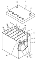
- FIG. 1 shows the appearance of an example of a lead storage battery according to an embodiment of the present invention.
- the lead-acid battery 1 includes an electric tank 12 that houses a electrode plate group 11 and an electrolytic solution (not shown).
- the inside of the electric tank 12 is partitioned into a plurality of cell chambers 14 by a partition wall 13.
- each cell chamber 14 one electrode plate group 11 is stored.
- the opening of the battery case 12 is closed by a lid 15 including a negative electrode terminal 16 and a positive electrode terminal 17.
- the lid 15 is provided with a liquid spout 18 for each cell chamber. At the time of rehydration, the liquid spout 18 is removed and the rehydration liquid is replenished.
- the liquid spout 18 may have a function of discharging the gas generated in the cell chamber 14 to the outside of the battery.
- the electrode plate group 11 is formed by laminating a plurality of negative electrode plates 2 and positive electrode plates 3 via a separator 4, respectively.
- the bag-shaped separator 4 that accommodates the negative electrode plate 2 is shown, but the form of the separator is not particularly limited.
- the negative electrode shelf portion 6 for connecting the plurality of negative electrode plates 2 in parallel is connected to the through connecting body 8, and the positive electrode shelf portion for connecting the plurality of positive electrode plates 3 in parallel. 5 is connected to the positive electrode column 7.
- the positive electrode column 7 is connected to the positive electrode terminal 17 outside the lid 15.
- the negative electrode column 9 is connected to the negative electrode shelf 6, and the through connector 8 is connected to the positive electrode shelf 5.
- the negative electrode column 9 is connected to the negative electrode terminal 16 outside the lid 15.
- Each through-connecting body 8 passes through a through-hole provided in the partition wall 13 and connects the electrode plates 11 of the adjacent cell chambers 14 in series.
- the positive electrode shelf 5 is formed by welding the ears provided on the upper part of each positive electrode plate 3 by a cast-on strap method or a burning method.
- the negative electrode shelf portion 6 is also formed by welding the ear portions provided on the upper portions of the negative electrode plates 2 as in the case of the positive electrode shelf portion 5.
- the lid 15 of the lead storage battery has a single structure (single lid), but is not limited to the case shown in the illustrated example.
- the lid 15 may have, for example, a double structure including an inner lid and an outer lid (or upper lid).
- the lid having a double structure may be provided with a reflux structure between the inner lid and the outer lid for returning the electrolytic solution to the inside of the battery (inside the inner lid) from the reflux port provided on the inner lid.
- the lead-acid batteries according to one aspect of the present invention are summarized below.
- a positive electrode plate, a negative electrode plate, and an electrolytic solution are provided.
- the positive electrode plate contains a positive electrode current collector and a positive electrode material.
- the negative electrode plate contains a negative electrode current collector and a negative electrode material.
- the positive electrode current collector contains a lead alloy containing Ca and Sn, and contains The Ca content in the positive electrode current collector is 0.2% by mass or less, and the Sn content is 0.5% by mass or more.
- the negative electrode material is a lead-acid battery containing a first organic shrink-proofing agent (excluding a lignin compound) containing at least one selected from the group consisting of a unit of a monocyclic aromatic compound and a unit of a bisphenol S compound.
- the content of Ca in the positive electrode current collector may be 0.14% by mass or less, or 0.12% by mass or less.
- the content of Ca in the positive electrode current collector is 0.01% by mass or more, 0.03% by mass or more, or 0.04% by mass or more. May be good.
- the Sn content in the positive electrode current collector may be 0.8% by mass or more, or 1.0% by mass or more. ..
- the Sn content in the positive electrode current collector may be 5% by mass or less, or 3% by mass or less.
- the negative electrode material may further contain barium sulfate.
- the content of the barium sulfate in the negative electrode material is 0.05% by mass or more, 0.1% by mass or more, 0.5% by mass or more, 0.6% by mass or more. , Or 0.8% by mass or more.
- the content of the barium sulfate in the negative electrode material may be 5% by mass or less, or 3% by mass or less.
- the first organic shrinkage proofing agent is a unit of the monocyclic aromatic compound (first unit) and a unit of another aromatic compound (1 unit). Second unit) and may be included.
- the second unit may contain at least a unit of a bisphenol compound, and the unit of the bisphenol compound is selected from the group consisting of a unit of a bisphenol S compound and a unit of a bisphenol A compound. It may be at least one kind.
- the unit of the bisphenol compound may include at least a unit of the bisphenol S compound.
- the unit of the monocyclic aromatic compound may include at least a unit of phenol sulfonic acid.
- the molar ratio of the first unit to the total amount of the first unit and the second unit is 10 mol% or more, 20 mol% or more. It may be 40 mol% or more, or 50 mol% or more.
- the molar ratio of the first unit to the total amount of the first unit and the second unit is 90 mol% or less, or 80 mol% or less. It may be.
- the first organic shrinkage proofing agent may include a unit of the bisphenol S compound and a unit of the bisphenol A compound.
- the molar ratio of the bisphenol S compound unit to the total amount of the bisphenol S compound unit and the bisphenol A compound unit in the first organic shrinkage proofing agent is 40 mol% or more. There may be.
- the molar ratio of the bisphenol S compound unit to the total amount of the bisphenol S compound unit and the bisphenol A compound unit is 10 mol% or more, 20 mol% or more. , 40 mol% or more, or 50 mol% or more.
- the molar ratio of the bisphenol S compound unit to the total amount of the bisphenol S compound unit and the bisphenol A compound unit is 90 mol% or less. , Or 80 mol% or less.
- the sulfur element content of the first organic shrinkage proofing agent may be 8000 ⁇ mol / g or less, or 7000 ⁇ mol / g or less.
- the sulfur element content of the first organic shrinkage proofing agent may be less than 2000 ⁇ mol / g.
- the sulfur element content of the first organic shrinkage proofing agent may be 300 ⁇ mol / g or more.
- the weight average molecular weight (Mw) of the organic shrinkage proofing agent may be 7,000 or more.
- the weight average molecular weight (Mw) of the organic shrinkage proofing agent may be 100,000 or less, or 20,000 or less.
- the content of the organic shrinkage-proofing agent contained in the negative electrode electrode material (organic shrinkage-proofing agent other than the first organic shrinkage-proofing agent and the first organic shrinkage-proofing agent).
- the total content of the agents (second organic shrinkage proofing agent) may be 0.01% by mass or more and 0.05% by mass or more.
- the content of the organic shrinkage-proofing agent contained in the negative electrode electrode material (organic shrinkage-proofing agent other than the first organic shrinkage-proofing agent and the first organic shrinkage-proofing agent).
- the total content of the agents (second organic shrinkage proofing agent) may be 1.0% by mass or less, or 0.5% by mass or less.
- the negative electrode material may further contain a carbonaceous material.
- the content of the carbonaceous material in the negative electrode material may be 0.05% by mass or more, or 0.10% by mass or more.
- the content of the carbonaceous material in the negative electrode material may be 5% by mass or less, or 3% by mass or less.
- the specific gravity of the electrolytic solution in the fully charged lead-acid battery at 20 ° C. may be 1.20 or more, or 1.25 or more. ..
- the specific gravity of the electrolytic solution in the fully charged lead-acid battery at 20 ° C. may be 1.35 or less, or 1.32 or less. ..
- Lead powder, water, dilute sulfuric acid, carbon black, organic shrink-proofing agent, and if necessary, barium sulfate are mixed to obtain a negative electrode paste.
- the content of the organic shrinkage-proofing agent and the content of carbon black in the negative electrode material obtained by the above-mentioned procedure are 0.10% by mass and 0.30% by mass, respectively. Mix the ingredients.
- barium sulfate is mixed with other components so that the barium sulfate content obtained by the above-mentioned procedure has the value shown in Table 1.
- the negative electrode paste is filled in the mesh portion of the expanded lattice made of Pb—Ca—Sn alloy as the negative electrode current collector, and aged and dried to obtain an unchemicald negative electrode plate.
- the condensate shown in Table 1 is used as the organic shrinkage proofing agent.
- the condensates shown in Table 1 are as follows.
- the molar ratio of the monomers in each organic shrinkage proofing agent corresponds to the molar ratio of the units obtained in the procedure described above.
- b1 Sodium lignin sulfonate (sulfur element content: 600 ⁇ mol / g, Mw: 5500)
- b2 Condensation product of bisphenol A and formaldehyde in the presence of sodium sulfite (sulfur element content: 3000 ⁇ mol / g, Mw: 9000)
- (B) Preparation of Positive Electrode Plate The lead powder as a raw material is mixed with an aqueous sulfuric acid solution to obtain a positive electrode paste.
- the positive electrode paste is filled in the mesh portion of the lead alloy lattice as the positive electrode current collector and aged and dried to obtain an unchemicald positive electrode plate.
- As the positive electrode current collector an expanded lattice made of a Pb—Ca—Sn alloy whose Ca content and Sn content obtained in the above procedure are the values shown in Table 1 is used.
- (C) Preparation of Lead-acid Battery The unchemicald negative electrode plate is housed in a bag-shaped separator formed of a polyethylene microporous film, and the electrode plate is composed of five unchemicald negative electrode plates and four unchemicald positive electrode plates. Form a group. A group of plates is inserted into the battery case, an electrolytic solution is injected, and chemical conversion is performed in the battery case. The rated voltage of the lead battery is 12V, and the rated capacity is 30Ah (5-hour rate). Lead-acid batteries E1 to E3 and R1 to R5 are manufactured. As the electrolytic solution, an aqueous sulfuric acid solution having a specific gravity of 1.28 (20 ° C.) after chemical conversion is used. The lead-acid battery is fully charged due to the above chemical formation.
- the discharge duration is determined by the procedure (2-1) and (a) above.
- the ratio (%) when the discharge duration of the lead storage battery B1-2 is 100 is used as an index of the low temperature HR discharge performance. The results are shown in Table 1.
- lead-acid batteries using the first organic shrinkage proofing agents a1 to a3 have low-temperature HR discharge performance after a charge / discharge cycle as compared with lead-acid batteries using a condensate of sodium lignin sulfonate or bisphenol A. Is significantly improved.
- lead-acid batteries using sodium lignin sulfonate even if the Ca content, Sn content, or barium sulfate content in the positive electrode current collector is changed, the change in low-temperature HR discharge performance after the charge / discharge cycle is 4%. It is as follows.
- the lead storage battery using the first organic shrinkage proofing agent the low temperature HR discharge performance after the charge / discharge cycle is greatly improved to 8% to 50%.
- the low temperature HR discharge performance after the cycle is remarkably improved when the Ca content in the positive electrode current collector is 0.2% by mass or less as compared with the case where the Ca content exceeds 0.2% by mass.
- the low temperature HR discharge performance after the cycle is remarkably improved even when the Sn content in the positive electrode current collector is 0.5% by mass or more as compared with the case where the Sn content is less than 0.5% by mass.
- such an improving effect cannot be obtained when sodium lignin sulfonate is used, and it can be said that it is an effect peculiar to the first organic shrinkage proofing agent.
- the charge acceptability and the low temperature HR discharge performance after the charge / discharge cycle are almost changed even if the barium sulfate content is increased from 0.6% by mass to 0.8% by mass. Absent.
- the content of barium sulfate is preferably 0.8% by mass or more from the viewpoint of ensuring higher charge acceptability and low-temperature HR discharge performance after the charge / discharge cycle.
- the negative electrode plate and lead storage battery according to one aspect of the present invention are applicable to control valve type and liquid type lead storage batteries.
- the lead-acid battery can be suitably used as, for example, a power source for starting an automobile or a motorcycle, a storage device for natural energy, and a power source for an industrial power storage device such as an electric vehicle (forklift or the like). It should be noted that these uses are merely examples and are not limited to these uses.
Landscapes
- Chemical & Material Sciences (AREA)
- Chemical Kinetics & Catalysis (AREA)
- Electrochemistry (AREA)
- General Chemical & Material Sciences (AREA)
- Engineering & Computer Science (AREA)
- Materials Engineering (AREA)
- Manufacturing & Machinery (AREA)
- Mechanical Engineering (AREA)
- Metallurgy (AREA)
- Organic Chemistry (AREA)
- Battery Electrode And Active Subsutance (AREA)
Priority Applications (3)
| Application Number | Priority Date | Filing Date | Title |
|---|---|---|---|
| US17/763,540 US11894560B2 (en) | 2019-09-27 | 2020-09-24 | Lead-acid battery |
| CN202080067273.1A CN114514632A (zh) | 2019-09-27 | 2020-09-24 | 铅蓄电池 |
| JP2021548958A JP7622635B2 (ja) | 2019-09-27 | 2020-09-24 | 鉛蓄電池 |
Applications Claiming Priority (2)
| Application Number | Priority Date | Filing Date | Title |
|---|---|---|---|
| JP2019178093 | 2019-09-27 | ||
| JP2019-178093 | 2019-09-27 |
Publications (1)
| Publication Number | Publication Date |
|---|---|
| WO2021060325A1 true WO2021060325A1 (ja) | 2021-04-01 |
Family
ID=75166982
Family Applications (1)
| Application Number | Title | Priority Date | Filing Date |
|---|---|---|---|
| PCT/JP2020/035916 Ceased WO2021060325A1 (ja) | 2019-09-27 | 2020-09-24 | 鉛蓄電池 |
Country Status (5)
| Country | Link |
|---|---|
| US (1) | US11894560B2 (https=) |
| JP (1) | JP7622635B2 (https=) |
| CN (1) | CN114514632A (https=) |
| TW (1) | TWI859325B (https=) |
| WO (1) | WO2021060325A1 (https=) |
Families Citing this family (1)
| Publication number | Priority date | Publication date | Assignee | Title |
|---|---|---|---|---|
| CN120637627A (zh) * | 2025-06-12 | 2025-09-12 | 天能电池集团(江西)有限公司 | 一种基于中央紧凑型极耳的高性价比动力铅酸蓄电池系统 |
Citations (5)
| Publication number | Priority date | Publication date | Assignee | Title |
|---|---|---|---|---|
| JP2002134114A (ja) * | 2000-10-20 | 2002-05-10 | Japan Storage Battery Co Ltd | 鉛蓄電池 |
| JP2004071477A (ja) * | 2002-08-08 | 2004-03-04 | Japan Storage Battery Co Ltd | 鉛蓄電池の製造方法 |
| WO2017110594A1 (ja) * | 2015-12-25 | 2017-06-29 | 株式会社Gsユアサ | 鉛蓄電池 |
| JP2017155111A (ja) * | 2016-03-01 | 2017-09-07 | 日立化成株式会社 | フェノール系樹脂、電極、鉛蓄電池及びこれらの製造方法、並びに、樹脂組成物 |
| JP2018018742A (ja) * | 2016-07-29 | 2018-02-01 | 株式会社Gsユアサ | 制御弁式鉛蓄電池 |
Family Cites Families (30)
| Publication number | Priority date | Publication date | Assignee | Title |
|---|---|---|---|---|
| DE69115078T2 (de) * | 1990-02-15 | 1996-05-09 | Japan Storage Battery Co Ltd | Geschlossene Bleisäurebatterie. |
| JPH10302783A (ja) | 1997-04-25 | 1998-11-13 | Shin Kobe Electric Mach Co Ltd | 密閉形鉛蓄電池及びその製造法 |
| JP3091167B2 (ja) | 1997-07-16 | 2000-09-25 | 古河電池株式会社 | 鉛蓄電池 |
| JP2000021413A (ja) | 1998-07-06 | 2000-01-21 | Shin Kobe Electric Mach Co Ltd | 鉛蓄電池用正極格子体 |
| JP4422829B2 (ja) | 1998-09-18 | 2010-02-24 | パナソニック株式会社 | 鉛蓄電池 |
| KR100311945B1 (ko) | 1998-09-18 | 2001-11-03 | 모리시타 요이찌 | 납 축전지 |
| US6649306B2 (en) * | 2000-01-19 | 2003-11-18 | Rsr Technologies, Inc. | Alloy for thin positive grid for lead acid batteries and method for manufacture of grid |
| JP4590813B2 (ja) | 2002-05-21 | 2010-12-01 | パナソニック株式会社 | 鉛蓄電池用セパレータおよびそれを用いた鉛蓄電池 |
| JP4325153B2 (ja) * | 2002-07-19 | 2009-09-02 | パナソニック株式会社 | 制御弁式鉛蓄電池 |
| JP2004281197A (ja) | 2003-03-14 | 2004-10-07 | Matsushita Electric Ind Co Ltd | 鉛蓄電池 |
| KR101068378B1 (ko) * | 2004-04-28 | 2011-09-28 | 파나소닉 주식회사 | 납축전지 |
| TWI333290B (en) * | 2004-06-16 | 2010-11-11 | Panasonic Corp | Lead-acid battery |
| WO2007036979A1 (ja) | 2005-09-27 | 2007-04-05 | The Furukawa Battery Co., Ltd. | 鉛蓄電池及び鉛蓄電池の製造方法 |
| AR064292A1 (es) * | 2006-12-12 | 2009-03-25 | Commw Scient Ind Res Org | Dispositivo mejorado para almacenamiento de energia |
| AR067238A1 (es) * | 2007-03-20 | 2009-10-07 | Commw Scient Ind Res Org | Dispositivos optimizados para el almacenamiento de energia |
| US8404382B2 (en) * | 2008-04-08 | 2013-03-26 | Trojan Battery Company | Flooded lead-acid battery and method of making the same |
| JP5884528B2 (ja) | 2012-02-03 | 2016-03-15 | 株式会社Gsユアサ | 液式鉛蓄電池 |
| JP6060909B2 (ja) | 2012-02-14 | 2017-01-25 | 日立化成株式会社 | 鉛蓄電池用正極板及び該極板の製造方法並びにこの正極板を用いた鉛蓄電池 |
| WO2013150754A1 (ja) | 2012-04-06 | 2013-10-10 | 株式会社Gsユアサ | 液式鉛蓄電池 |
| EP3059791B1 (en) | 2013-10-15 | 2021-12-29 | GS Yuasa International Ltd. | Valve-regulated lead-acid battery |
| CN106133967B (zh) * | 2014-03-28 | 2019-08-23 | 日立化成株式会社 | 铅蓄电池以及铅蓄电池用的电极集电体 |
| CN106463729B (zh) * | 2014-05-26 | 2020-04-03 | 株式会社杰士汤浅国际 | 铅蓄电池 |
| WO2016088836A1 (ja) | 2014-12-05 | 2016-06-09 | 日立化成株式会社 | ビスフェノール系樹脂、電極、鉛蓄電池及びこれらの製造方法 |
| US10276895B2 (en) * | 2015-01-08 | 2019-04-30 | Gs Yuasa International Ltd. | Positive electrode grid for lead acid batteries and method for producing the same, and lead acid battery |
| JP6652133B2 (ja) * | 2015-05-29 | 2020-02-19 | 株式会社Gsユアサ | 鉛蓄電池および鉛蓄電池の製造方法 |
| JP6468163B2 (ja) | 2015-10-21 | 2019-02-13 | 日立化成株式会社 | 鉛蓄電池 |
| JP6589633B2 (ja) * | 2015-12-25 | 2019-10-16 | 株式会社Gsユアサ | 鉛蓄電池 |
| CN108780874B (zh) * | 2016-03-15 | 2021-04-13 | 株式会社杰士汤浅国际 | 铅蓄电池 |
| CN110072964B (zh) * | 2016-12-20 | 2021-05-25 | Dic株式会社 | 电池用包装材料用粘接剂、电池用包装材料、电池用容器及电池 |
| DE112018002253T5 (de) * | 2017-04-28 | 2020-01-23 | Gs Yuasa International Ltd. | Blei-säure-batterie |
-
2020
- 2020-09-10 TW TW109131017A patent/TWI859325B/zh active
- 2020-09-24 US US17/763,540 patent/US11894560B2/en active Active
- 2020-09-24 WO PCT/JP2020/035916 patent/WO2021060325A1/ja not_active Ceased
- 2020-09-24 CN CN202080067273.1A patent/CN114514632A/zh active Pending
- 2020-09-24 JP JP2021548958A patent/JP7622635B2/ja active Active
Patent Citations (5)
| Publication number | Priority date | Publication date | Assignee | Title |
|---|---|---|---|---|
| JP2002134114A (ja) * | 2000-10-20 | 2002-05-10 | Japan Storage Battery Co Ltd | 鉛蓄電池 |
| JP2004071477A (ja) * | 2002-08-08 | 2004-03-04 | Japan Storage Battery Co Ltd | 鉛蓄電池の製造方法 |
| WO2017110594A1 (ja) * | 2015-12-25 | 2017-06-29 | 株式会社Gsユアサ | 鉛蓄電池 |
| JP2017155111A (ja) * | 2016-03-01 | 2017-09-07 | 日立化成株式会社 | フェノール系樹脂、電極、鉛蓄電池及びこれらの製造方法、並びに、樹脂組成物 |
| JP2018018742A (ja) * | 2016-07-29 | 2018-02-01 | 株式会社Gsユアサ | 制御弁式鉛蓄電池 |
Also Published As
| Publication number | Publication date |
|---|---|
| US20220344668A1 (en) | 2022-10-27 |
| CN114514632A (zh) | 2022-05-17 |
| TW202118131A (zh) | 2021-05-01 |
| JP7622635B2 (ja) | 2025-01-28 |
| TWI859325B (zh) | 2024-10-21 |
| JPWO2021060325A1 (https=) | 2021-04-01 |
| US11894560B2 (en) | 2024-02-06 |
Similar Documents
| Publication | Publication Date | Title |
|---|---|---|
| WO2020241878A1 (ja) | 鉛蓄電池 | |
| JP2024059783A (ja) | 鉛蓄電池 | |
| JP6756182B2 (ja) | 鉛蓄電池 | |
| JP6766504B2 (ja) | 鉛蓄電池 | |
| JP2026012774A (ja) | 鉛蓄電池、電源装置および電源装置の使用方法 | |
| WO2021060325A1 (ja) | 鉛蓄電池 | |
| JP7363288B2 (ja) | 鉛蓄電池用負極板および鉛蓄電池、ならびに鉛蓄電池用負極板の製造方法 | |
| JP6733402B2 (ja) | 鉛蓄電池 | |
| JP7230906B2 (ja) | 鉛蓄電池用負極板および鉛蓄電池 | |
| JPWO2018199123A1 (ja) | 鉛蓄電池 | |
| JP7314747B2 (ja) | 鉛蓄電池用負極板およびそれを備える鉛蓄電池 | |
| JP7666326B2 (ja) | 鉛蓄電池 | |
| JP7099448B2 (ja) | 鉛蓄電池 | |
| JP7099452B2 (ja) | 鉛蓄電池 | |
| WO2021060324A1 (ja) | 鉛蓄電池用負極板および鉛蓄電池 | |
| JPWO2019225161A1 (ja) | 鉛蓄電池 | |
| JP2021061171A (ja) | 鉛蓄電池 | |
| JP2020102359A (ja) | 鉛蓄電池 | |
| JP2025039252A (ja) | 液式鉛蓄電池 | |
| WO2025053153A1 (ja) | 液式鉛蓄電池 | |
| WO2025053154A1 (ja) | 液式鉛蓄電池 | |
| JP2022085745A (ja) | 鉛蓄電池 |
Legal Events
| Date | Code | Title | Description |
|---|---|---|---|
| 121 | Ep: the epo has been informed by wipo that ep was designated in this application |
Ref document number: 20869444 Country of ref document: EP Kind code of ref document: A1 |
|
| ENP | Entry into the national phase |
Ref document number: 2021548958 Country of ref document: JP Kind code of ref document: A |
|
| NENP | Non-entry into the national phase |
Ref country code: DE |
|
| 122 | Ep: pct application non-entry in european phase |
Ref document number: 20869444 Country of ref document: EP Kind code of ref document: A1 |