WO2021059767A1 - 電気接続箱 - Google Patents
電気接続箱 Download PDFInfo
- Publication number
- WO2021059767A1 WO2021059767A1 PCT/JP2020/030158 JP2020030158W WO2021059767A1 WO 2021059767 A1 WO2021059767 A1 WO 2021059767A1 JP 2020030158 W JP2020030158 W JP 2020030158W WO 2021059767 A1 WO2021059767 A1 WO 2021059767A1
- Authority
- WO
- WIPO (PCT)
- Prior art keywords
- heat radiating
- radiating member
- plate portion
- bus bar
- electric
- Prior art date
- Legal status (The legal status is an assumption and is not a legal conclusion. Google has not performed a legal analysis and makes no representation as to the accuracy of the status listed.)
- Ceased
Links
Images


Classifications
-
- H—ELECTRICITY
- H01—ELECTRIC ELEMENTS
- H01H—ELECTRIC SWITCHES; RELAYS; SELECTORS; EMERGENCY PROTECTIVE DEVICES
- H01H9/00—Details of switching devices, not covered by groups H01H1/00 - H01H7/00
- H01H9/52—Cooling of switch parts
-
- H—ELECTRICITY
- H02—GENERATION; CONVERSION OR DISTRIBUTION OF ELECTRIC POWER
- H02G—INSTALLATION OF ELECTRIC CABLES OR LINES, OR OF COMBINED OPTICAL AND ELECTRIC CABLES OR LINES
- H02G3/00—Installations of electric cables or lines or protective tubing therefor in or on buildings, equivalent structures or vehicles
- H02G3/02—Details
- H02G3/08—Distribution boxes; Connection or junction boxes
- H02G3/16—Distribution boxes; Connection or junction boxes structurally associated with support for line-connecting terminals within the box
-
- B—PERFORMING OPERATIONS; TRANSPORTING
- B60—VEHICLES IN GENERAL
- B60R—VEHICLES, VEHICLE FITTINGS, OR VEHICLE PARTS, NOT OTHERWISE PROVIDED FOR
- B60R16/00—Electric or fluid circuits specially adapted for vehicles and not otherwise provided for; Arrangement of elements of electric or fluid circuits specially adapted for vehicles and not otherwise provided for
- B60R16/02—Electric or fluid circuits specially adapted for vehicles and not otherwise provided for; Arrangement of elements of electric or fluid circuits specially adapted for vehicles and not otherwise provided for electric constitutive elements
- B60R16/023—Electric or fluid circuits specially adapted for vehicles and not otherwise provided for; Arrangement of elements of electric or fluid circuits specially adapted for vehicles and not otherwise provided for electric constitutive elements for transmission of signals between vehicle parts or subsystems
- B60R16/0239—Electronic boxes
-
- H—ELECTRICITY
- H02—GENERATION; CONVERSION OR DISTRIBUTION OF ELECTRIC POWER
- H02B—BOARDS, SUBSTATIONS OR SWITCHING ARRANGEMENTS FOR THE SUPPLY OR DISTRIBUTION OF ELECTRIC POWER
- H02B1/00—Frameworks, boards, panels, desks, casings; Details of substations or switching arrangements
- H02B1/56—Cooling; Ventilation
- H02B1/565—Cooling; Ventilation for cabinets
-
- H—ELECTRICITY
- H02—GENERATION; CONVERSION OR DISTRIBUTION OF ELECTRIC POWER
- H02G—INSTALLATION OF ELECTRIC CABLES OR LINES, OR OF COMBINED OPTICAL AND ELECTRIC CABLES OR LINES
- H02G3/00—Installations of electric cables or lines or protective tubing therefor in or on buildings, equivalent structures or vehicles
- H02G3/02—Details
- H02G3/03—Cooling
-
- H—ELECTRICITY
- H01—ELECTRIC ELEMENTS
- H01R—ELECTRICALLY-CONDUCTIVE CONNECTIONS; STRUCTURAL ASSOCIATIONS OF A PLURALITY OF MUTUALLY-INSULATED ELECTRICAL CONNECTING ELEMENTS; COUPLING DEVICES; CURRENT COLLECTORS
- H01R13/00—Details of coupling devices of the kinds covered by groups H01R12/70 or H01R24/00 - H01R33/00
- H01R13/66—Structural association with built-in electrical component
- H01R13/68—Structural association with built-in electrical component with built-in fuse
-
- H—ELECTRICITY
- H01—ELECTRIC ELEMENTS
- H01R—ELECTRICALLY-CONDUCTIVE CONNECTIONS; STRUCTURAL ASSOCIATIONS OF A PLURALITY OF MUTUALLY-INSULATED ELECTRICAL CONNECTING ELEMENTS; COUPLING DEVICES; CURRENT COLLECTORS
- H01R31/00—Coupling parts supported only by co-operation with counterpart
- H01R31/06—Intermediate parts for linking two coupling parts, e.g. adapter
- H01R31/065—Intermediate parts for linking two coupling parts, e.g. adapter with built-in electric apparatus
Definitions
- the present disclosure relates to electrical junction boxes.
- This application claims priority based on Japanese Application No. 2019-175970 filed on September 26, 2019, and incorporates all the contents described in the Japanese application.
- the electric wires mounted on the vehicle and supplying electric power from the vehicle battery to each vehicle load in the vehicle are once connected to the electric junction box (junction box) and connected to each vehicle load via the electric junction box (for example,).
- Patent Document 1 The electric connection box of Patent Document 1 includes a relay and a box body to which the relay is fixed.
- the electric junction box is an electric junction box mounted on a vehicle, and electrically connects a plurality of electric components electrically connected to a power storage device mounted on the vehicle or an in-vehicle load.
- a plurality of bus bars that are thermally connected to each other include the plurality of electrical components and a housing that accommodates the bus bars, and an insulating heat radiating member that is thermally connected to the bus bars and the housing. At least two electric components in the electric component are arranged next to each other, and the bus bar dissipates heat generated from the two electric components via the heat radiating member.
- FIG. It is the schematic which shows the vehicle which mounted the electric junction box which concerns on Embodiment 1.
- FIG. It is a perspective view which showed the appearance of the electric junction box substantially. It is a side sectional view which shows the inside of an electric junction box. It is explanatory drawing which shows the state which two electric components are connected by the bus bar.
- Basba It is a plan view of Basba. It is a side view of Basba. It is a perspective view which substantially showed the appearance of the electric connection box which concerns on Embodiment 2.
- FIG. It is a side sectional view which shows the inside of an electric junction box.
- An object of the present disclosure is to provide an electric junction box capable of efficiently dissipating heat generated by electrical parts housed in the electrical junction box.
- the electric junction box is an electric junction box mounted on a vehicle, and a plurality of electric components electrically connected to a power storage device mounted on the vehicle or an in-vehicle load.
- a bus bar that is electrically and thermally connected, a housing that houses the plurality of electrical components and the bus bar, and an insulating heat radiating member that is thermally connected to the bus bar and the housing.
- At least two electric components in the plurality of electric components are arranged next to each other, and the bus bar dissipates heat generated from the two electric components via the heat radiating member.
- the two electric components to be heat-dissipated are arranged next to each other, the length of the bus bar connecting these two electric components in the extending direction is shortened, and the thermal resistance in the bus bar is reduced. Can be made to.
- the heat generated by the two electric components is efficiently transferred to the bus bar connecting these electric components, and is dissipated to the outside of the electric junction box via the heat radiating member and the housing thermally connected to the bus bar. To. Therefore, heat generated from a plurality of electric components arranged adjacent to each other can be efficiently dissipated by a single bus bar and a heat radiating member.
- the bus bar includes a first plate portion that is in close contact with at least one of the two electrical components, and the bus bar is one of the electrical components.
- a laminated structure is formed by the first plate portion, the heat radiating member, and the housing portion to which the heat radiating member is attached.
- the bus bar includes a first plate portion that is in close contact with any of the electric components, and the electric component of the deviation, the first plate portion of the bus bar, the heat radiating member, and the housing to which the heat radiating member is attached.
- the portions form a laminated structure that is in surface contact with each other. Since the two electric parts are arranged next to each other, the heat generated from the two electric parts is efficiently transferred to the housing of the electric junction box by the laminated structure including the first plate portion of the bus bar. The heat generation can be efficiently dissipated to the outside of the electric junction box.
- the heat radiating member has a sheet shape, and the area of the heat radiating member is in close contact with any of the electric parts in the first plate portion. Larger than the area of the area.
- the contact area and the heat radiating member are viewed in a plan view.
- the bus bar and the heat radiating member can be laminated with each other without fail.
- the electric connection box includes a second heat radiating member provided on the outer surface of the housing, the heat radiating member, a portion of the housing to which the heat radiating member is attached, and the first. 2
- the heat radiating member forms a laminated structure.
- the second heat radiating member since the heat radiating member, the portion of the housing to which the heat radiating member is attached, and the second heat radiating member form a laminated structure in which they are in surface contact with each other, the second heat radiating member is positioned outside the housing. It is possible to promote heat exchange with a cold heat source such as ambient air. Therefore, the heat generated by the two electric components arranged next to each other can be more efficiently dissipated to the outside of the electric junction box.
- the heat radiating member and the second heat radiating member have the same material and shape.
- the heat radiating member and the second heat radiating member have the same material and shape, they are treated as the same part (product number), and the heat radiating member and the second heat radiating member are attached to the housing at the manufacturing stage. It is possible to prevent misassembly at the time.
- the bus bar has a first plate portion that is in close contact with one of the two electric components and a second plate portion that is in close contact with the other electric component.
- the connecting plate portion interposed between the first plate portion and the second plate portion, and the surface width of the connecting plate portion in the extending direction of the bus bar is the first plate portion and the first plate portion. It is smaller than the surface width of the two plates.
- the bus bar since the bus bar includes a first plate portion and a second plate portion that are in close contact with each of the two electric components, the heat generated from the electric components is efficiently transferred to the bus bar by the first plate portion and the second plate portion. Can be told to. Since the surface width of the connecting plate portion interposed between the first plate portion and the second plate portion is smaller than the surface width of either the first plate portion or the second plate portion, the thermal resistance of the bus bar should be reduced. Can be done. Therefore, the heat generated from these electric components can be efficiently transferred to the heat radiating member and radiated to the outside of the electric junction box.
- the amount of heat generated per unit time of each of the two electric components when power is supplied from the power storage device to the vehicle-mounted load is different, and the heat radiation member. Is provided on the side of the electric component that generates a large amount of heat among the two electric components.
- the heat radiating member is provided on the side of the electric component that generates a large amount of heat among the two electric components, the heat generated from the two electric components to the bus bar is transferred to the bus bar via the heat radiating member. Efficiently dissipates heat to the outside of the electric junction box, and the size of the heat dissipation member is made to correspond to the electric parts that generate a large amount of heat to prevent the heat dissipation member from becoming large. It is possible to reduce the size, size and weight.
- the two electrical components are a relay and a fuse.
- the heat generated from the relay and the fuse can be efficiently dissipated to the outside of the electric junction box.
- the electric junction box includes a temperature sensor that detects heat generated by the two electric components, and the temperature sensor is provided on the bus bar.
- the temperature sensor is provided on the bus bar, the heat generated from the electric components arranged adjacent to each other can be detected by a single temperature sensor, and the temperature sensor mounted on the electric junction box. It is possible to reduce the number of parts, reduce the cost of parts of the electric junction box, and reduce the size and weight.
- FIG. 1 is a schematic view showing a vehicle C on which the electrical connection box 1 according to the first embodiment is mounted.
- the electric junction box 1 in the present embodiment is mounted on the vehicle C, and is provided between the power storage device 100 mounted on the vehicle C and the vehicle-mounted load 101.
- the power storage device 100 and the vehicle-mounted load 101 are electrically connected by an electric wire 102 via the electric connection box 1.
- the vehicle-mounted load 101 is described as one, but the number of vehicle-mounted loads 101 is not limited to a single number.
- the number of vehicle-mounted loads 101 mounted on the vehicle C may be plural, and a branch portion is provided between the electric connection box 1 and the plurality of vehicle-mounted loads 101, and the branch portion is connected to the positive electrode of the power storage device 100.
- the electric wire 102 may be branched, and the branched electric wire 102 may be connected to each of the plurality of vehicle-mounted loads 101.
- the electric junction box 1 is connected to the positive electrode side of the power storage device 100, but the present invention is not limited to this.
- the electric junction box 1 may be connected to the negative electrode side of the power storage device 100.
- the electric junction box 1 may be connected to the positive electrode side and the negative electrode side of the power storage device 100, respectively.
- the power storage device 100 is, for example, a high-pressure battery for EV (Electric Vehicle) such as a lead battery or a lithium ion battery.
- EV Electric Vehicle
- the electrical junction box 1 stores the electrical components 40.
- the electric component 40 includes, for example, a fuse 42 and a relay 41.
- the relay 41 may be a mechanical relay or a semiconductor relay.
- the fuse 42 and the relay 41 included in the electric component 40 are connected by a bus bar to form a series circuit.
- the relay 41 and the vehicle-mounted load 101 are connected via the second bus bar 7.
- the fuse 42 and the power storage device 100 are connected via a third bus bar 8.
- the relay 41 is communicably connected to an ECU (not shown) of the power control system mounted on the vehicle C by a signal line, and is turned on or off according to a signal output from the ECU.
- FIG. 2 is a perspective view illustrating the appearance of the electrical connection box 1.
- the electrical junction box 1 includes a housing 2 forming an outer shell.
- the housing 2 is a rectangular parallelepiped made of an insulating resin, and includes an upper case 21 and a lower case 22. It is desirable that the housing 2 is made of a heat-dissipating resin such as heat-dissipating polypropylene or heat-dissipating polyamide resin.
- the upper case 21 forms a box body having an opening. Inside the upper case 21, for example, a fixing member (not shown) constituting the inner wall of the upper case 21 is provided.
- the electric component 40 including the relay 41 and the fuse 42 is fixed to the inside of the upper case 21 by the fixing member.
- the lower case 22 forms, for example, a plate-shaped or dish-shaped lid, and is provided so as to close the opening of the upper case 21.
- the housing 2 forming the outer shell of the electrical connection box 1 is configured.
- the electrical connection box 1 configured in this way is placed in the vicinity of the power storage device 100, for example.
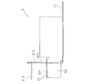
- FIG. 3 is a side sectional view illustrating the inside of the electrical connection box 1.
- FIG. 4 is an explanatory diagram showing a state in which two electric components 40 are connected by a bus bar 5. 3 and 4 are shown with the opening side of the upper case 21 as the upper side.
- FIG. 3 is a schematic view of a side cross section parallel to the longitudinal direction of the housing 2.
- FIG. 4 is a perspective view showing a state in which the fuse 42 and the relay 41 are connected by the bus bar 5 with the upper case 21 removed.
- the electric junction box 1 includes a plurality of electric components 40 including a fuse 42 and a relay 41, a bus bar 5, a second bus bar 7, a third bus bar 8, a temperature sensor 6, a heat radiating member 31, and a second heat radiating member 32.
- a plurality of electric components 40 including a fuse 42 and a relay 41, a bus bar 5 connecting the fuse 42 and the relay 41, a second bus bar 7, a temperature sensor 6, and a heat radiating member 31 are uppers constituting the housing 2 of the electric connection box 1. It is housed inside the case 21.
- the second heat radiating member 32 is attached to the outer surface of the upper case 21.
- the relay 41 forms a rectangular parallelepiped. On one side surface of the relay 41, relay terminals 411 on the positive electrode side and the relay terminal 411 on the negative electrode side are provided side by side. An insulating wall is provided between the relay terminals 411 on the positive electrode side and the negative electrode side so as to project from the one side surface.
- the fuse 42 forms a rectangular parallelepiped. Fuse terminals 421 on the positive electrode side and the negative electrode side are provided on one side surface of the fuse 42 and the other side surface facing the one side surface, respectively. As shown in FIGS. 3 and 4, the fuse 42 and the relay 41 are arranged adjacent to each other with their side surfaces facing each other.
- the fuse 42 is located and connected to the positive electrode side of the power storage device 100 with respect to the relay 41 (see FIG. 1), and the fuse terminal 421 on the positive electrode side of the fuse 42 is connected to the power storage device 100 via the third bus bar 8. It is connected to the positive electrode of.
- the fuse terminal 421 on the negative electrode side of the fuse 42 and the relay terminal 411 on the positive electrode side of the relay 41 are connected by a bus bar 5.
- the relay terminal 411 on the negative electrode side of the relay 41 is connected to the vehicle-mounted load 101 via the second bus bar 7.
- the bus bar 5 is made of a plate member having a plurality of bent portions, and is made of a metal having high conductivity and heat transfer coefficient by copper or a copper alloy or the like.
- the bus bar 5 includes a first plate portion 51, a second plate portion 52, and a connecting plate portion 53.
- a relay 41 is mounted on the first plate portion 51, and the relay 41 and the first plate portion 51 of the bus bar 5 are in close contact with each other.
- a fuse terminal 421 on the negative electrode side of the fuse 42 is fastened to the second plate portion 52, and the fuse terminal 421 on the negative electrode side of the fuse 42 and the second plate portion 52 of the bus bar 5 are in close contact with each other.
- the first plate portion 51 and the second plate portion 52 are provided so as to be substantially parallel to each other, and a connecting plate portion 53 is provided between the first plate portion 51 and the second plate portion 52. ..
- the second plate portion 52 to which the fuse terminal 421 is fastened is provided at a position higher than the first plate portion 51 on which the relay 41 is mounted, with the bottom surface of the upper case 21 as a reference. , It is provided so as to absorb the inter-plane distance caused by the difference in height between the first plate portion 51 and the second plate portion 52. Therefore, as shown in FIG. 3, the first plate portion 51, the connecting plate portion 53, and the second plate portion 52 form a crank shape in a side view.
- a first terminal fastening piece 511 bent substantially perpendicular to the first plate portion 51 is provided.
- a relay terminal 411 on the positive electrode side of the relay 41 is fastened to the first terminal fastening piece 511.
- a heat radiating member 31 is provided between the first plate portion 51 of the bus bar 5 and the bottom plate of the upper case 21. That is, the heat radiating member 31 is interposed between the first plate portion 51 and the upper case 21, and is in surface contact with the first plate portion 51 and the upper case 21 respectively. Therefore, a laminated structure is formed by the first plate portion 51 of the bus bar 5, the heat radiating member 31, and the bottom plate of the upper case 21, and the heat generated by the relay 41 and the fuse 42 via the bus bar 5 is efficiently transferred to the upper case. Heat can be dissipated from 21 to the electrical junction box 1 to the outside.
- the heat radiating member 31 is a resin heat radiating sheet having a rectangular sheet shape and having, for example, silicone-based, non-silicone-based or acrylic-based insulating and heat-transmitting properties.
- the heat radiating member 31 may be a graphite sheet whose surface is insulated.
- the area of the heat radiating member 31 is larger than the area of the region (contact region) in close contact with the relay 41 in the first plate portion 51 of the bus bar 5 on which the relay 41 is placed. Therefore, the region (adhesion region) in which the relay 41 and the first plate portion 51 are in close contact with each other and the heat radiating member are surely overlapped with each other in a plan view, and the bus bar 5 and the heat radiating member 31 are laminated to form the bus bar 5 And the heat transfer efficiency by the heat radiating member 31 can be improved.
- the surface width of the connecting plate portion 53 is the first plate portion 51 and the second plate in the extending direction of the bus bar 5, that is, the arrangement direction of the relay 41 and the fuse 42 connected by the bus bar 5. It is smaller than the surface width of the portion 52.
- the surface width of the connecting plate portion 53 can be made smaller than the surface width of the first plate portion 51 and the second plate portion 52. Thermal resistance can be reduced. Therefore, the heat generated by the fuse 42, which is transferred from the second plate portion 52, can be transferred to the connecting plate and the first plate portion 51, and can be dissipated from the heat radiating member 31.
- the fuse 42 and the relay 41 are provided next to each other, and the connecting plate portion 53 is provided between the side surfaces of the facing fuse 42 and the relay 41.
- the side surfaces of the facing fuse 42 and the relay 41 are close to each other, and the distance between the side surfaces of the facing fuse 42 and the relay 41 is, for example, within 5 times the size of the plate thickness of the connecting plate portion 53.
- the fuse 42 and the relay 41 are arranged next to each other.
- the heat radiating member 31 is provided so as to overlap with the first plate portion 51 on which the relay 41 is placed in a plan view. That is, the heat radiating member 31 is provided so as to be biased toward the side where the relay 41 is arranged in the extending direction of the bus bar 5.
- the amount of heat generated by the relay 41 in a unit time is larger than the amount of heat generated by the fuse 42.
- the heat radiating member 31 may be provided so as to overlap the plate portion of the second bus bar 7 connected to the relay terminal 411 on the negative electrode side of the relay 41.
- the plate portion of the second bus bar 7 is a plate portion on which the relay 41 is placed, similarly to the first plate portion 51 of the bus bar 5.
- a second heat radiating member 32 is provided on the outer surface of the bottom plate of the upper case 21. That is, the second heat radiating member 32 is attached to the outer surface of the housing 2 composed of the upper case 21 and the lower case 22.
- the second heat radiating member 32 is a resin heat radiating sheet having a rectangular sheet shape and having, for example, silicone-based, non-silicone-based or acrylic-based insulating and heat-transmitting properties.
- the second heat radiating member 32 may be a graphite sheet.
- the area of the second heat radiating member 32 is larger than the area of the region (contact region) in close contact with the relay 41 in the first plate portion 51 of the bus bar 5 on which the relay 41 is placed.
- a heat radiating member 31 is attached to the inner surface of the bottom plate of the upper case 21, and a second heat radiating member 32 is attached to the outer surface of the bottom plate of the upper case 21.
- a laminated structure was formed by the first plate portion 51 of the bus bar 5, the heat radiating member 31, the bottom plate of the upper case 21, and the second heat radiating member 32, which was generated by the relay 41 and the fuse 42 via the bus bar 5. Heat can be efficiently dissipated from the second heat radiating member 32 to the outside of the electric connection box 1.
- the second heat radiating member 32 is exposed to the outside of the electric connection box 1 and comes into contact with the ambient air of the electric connection box 1 or the chassis to which the electric connection box 1 is attached or other in-vehicle device of the cooling system. , Exchange heat with these chassis, etc. Therefore, the heat generated by the fuse 42 and the relay 41 can be efficiently dissipated to the outside of the electric junction box 1 and the temperature of the electric junction box 1 can be suppressed from rising.
- the second heat radiating member 32 is made of the same material as the heat radiating member 31, and may have the same shape and size. That is, the heat radiating member 31 and the second heat radiating member 32 may be managed as the same part number (part number) at the manufacturing stage of the electrical connection box 1.
- part number part number
- the second heat radiating member 32 has the same shape and size as the heat radiating member 31, the second heat radiating member 32 and the heat radiating member 31 are upper so that the second heat radiating member 32 and the heat radiating member 31 overlap each other in a plan view. It may be attached to the outer surface and the inner surface of the bottom plate of the case 21. By overlapping the second heat radiating member 32 and the heat radiating member 31 in a plan view and attaching them to the bottom plate of the upper case 21, the effect of radiating heat to the outside of the electric connection box 1 can be further improved.
- the first terminal fastening piece 511 of the bus bar 5 is provided with a temperature sensor 6 that detects and outputs a physical quantity related to the temperature of the bus bar 5.
- the temperature sensor 6 is attached to the surface of the first terminal fastening piece 511 opposite to the relay 41. Alternatively, the temperature sensor 6 may be attached to the surface of the first terminal fastening piece 511 on the side of the relay 41.
- the temperature sensor 6 may include, for example, a thermistor such as an NTC thermistor, a PTC thermistor, or a CTR thermistor, or may be a sensor using a thermocouple.
- the temperature sensor 6 is provided on the bus bar 5, and the bus bar 5 is connected to a relay 41 and a fuse 42 adjacent to each other in close proximity to each other. Therefore, the temperature due to the heat generated by the relay 41 and the fuse 42 can be detected by the single temperature sensor 6 provided in the bus bar 5, and the number of the temperature sensors 6 mounted on the electrical junction box 1 can be reduced. , It is possible to reduce the component cost, miniaturization and weight reduction of the electric junction box 1.
- the temperature sensor 6 is provided on the first terminal fastening piece 511, but the temperature sensor 6 is not limited to this.
- the temperature sensor 6 may be attached to the first plate portion 51, the connecting plate portion 53, or the second plate portion 52.
- FIG. 5 is a perspective view of the bus bar 5.
- FIG. 6 is a plan view of the bus bar 5.
- FIG. 7 is a side view of the bus bar 5.
- the bus bar 5 is a plate member having a plurality of bent portions and having high conductivity and heat transfer property, which is formed by bending and punching a sheet metal using copper or a copper alloy as a material.
- the bus bar 5 includes a first plate portion 51, a second plate portion 52, and a connecting plate portion 53 that connects the first plate portion 51 and the second plate portion 52.
- the first plate portion 51 has a rectangular shape in a plan view, and a relay 41 is placed on the surface of the first plate portion 51 (upper surface in FIG. 5).
- a heat radiating member 31 is attached to the back surface of the first plate portion 51 (lower surface in FIG. 5).
- a first terminal fastening piece 511 bent substantially perpendicular to the first plate portion 51 toward the side opposite to the first plate portion 51 is provided.
- the first terminal fastening piece 511 has a rectangular shape, and a first terminal fastening hole 512 for fastening the relay terminal 411 is provided on the peripheral side.
- a bent piece 513 bent substantially perpendicular to the first terminal fastening piece 511 is provided.
- the second plate portion 52 has a rectangular shape in a plan view, and a second terminal fastening hole 521 for fastening the fuse terminal 421 is provided in the central portion.
- a fuse terminal 421 having a rectangular plate shape is placed on the surface of the second plate portion 52 (upper surface in FIG. 5).
- the connecting plate portion 53 has a rectangular shape, is interposed between the first plate portion 51 and the second plate portion 52, and partially forms a heat transfer path from the first plate portion 51 to the second plate portion 52.
- the surface width of the connecting plate portion 53 is (D3) is smaller than the surface width (d1) of the first plate portion 51 and the surface width (d2) of the surface width of the second plate portion 52 (d3 ⁇ d1 and d3 ⁇ d2).
- the extending direction of the bus bar 5 is the arrangement direction of the fuse 42 and the relay 41 connected by the bus bar 5.
- the relay terminal 411 is connected from the second terminal fastening hole 521 to which the fuse terminal 421 is fastened. It may be in the direction toward the first terminal fastening hole 512 to be fastened.
- the connecting plate portion 53 is interposed between the first plate portion 51 and the second plate portion 52, and forms a part of the heat transfer path from the second plate portion 52 to the first plate portion 51.
- the distance of the heat transfer path can be reduced and the heat transfer resistance can be reduced. Therefore, the heat generated from the fuse 42 connected to the second plate portion 52 is efficiently transferred to the first plate portion 51, and the heat is transferred to the first plate portion 51 via the heat radiating member 31 provided so as to be overlapped with the first plate portion 51.
- the heat generated from the fuse 42 can be efficiently dissipated.
- FIG. 8 is a perspective view schematically showing the appearance of the electrical connection box 1 according to the second embodiment.
- FIG. 9 is a side sectional view illustrating the inside of the electrical connection box 1. Similar to the electrical junction box 1 of the first embodiment, the electrical junction box 1 according to the second embodiment has a plurality of electric components 40 including a fuse 42 and a relay 41, a bus bar 5, a second bus bar 7, a third bus bar 8, and a temperature sensor. 6.
- the heat radiating member 31 and the second heat radiating member 32 are included.
- a plurality of electric components 40 including a fuse 42 and a relay 41, a bus bar 5 connecting the fuse 42 and the relay 41, a second bus bar 7, a temperature sensor 6, and a heat radiating member 31 are uppers constituting the housing 2 of the electric connection box 1. It is housed inside the case 21.
- the sheet-shaped heat radiating member 31 is provided with one surface of its own member (heat radiating member 31) opposed to the inner surface of the lower case 22 provided so as to close the opening of the upper case 21, and is provided with one surface of the heat radiating member 31. It is in close contact with the inner surface of the lower case 22.
- the second heat radiating member 32 is attached to the outer surface of the lower case 22.
- the arrangement relationship between the electric component 40 such as the relay 41 and the fuse 42 and the bus bar 5 and the lower case 22 is the same as that of the electric component 40 and the bus bar 5 described in the first embodiment and the upper case 21. It is the same as the arrangement relationship with the bottom plate of.
- a laminated structure is formed by the sheet-shaped heat radiating member 31, the plate-shaped lower case 22, and the sheet-shaped second heat radiating member 32, and the heat generated by the relay 41 and the fuse 42 via the bus bar 5 is efficiently transferred. Heat can be dissipated from the lower case 22 to the electrical connection box 1 to the outside.
- the lower case 22 is interposed between the heat radiating member 31 and the second heat radiating member 32 to form a laminated structure by the heat radiating member 31, the lower case 22 and the second heat radiating member 32.
- the bottom plate of the upper case 21 is interposed between the heat radiating member 31 and the second heat radiating member 32 to form a laminated structure of the heat radiating member 31, the bottom plate of the upper case 21 and the second heat radiating member 32.
- the arrangement of the heat radiating member 31 and the second heat radiating member 32 with respect to the upper case 21 and the lower case 22 constituting the housing 2 is based on the shape and arrangement of the fuse 42, the relay 41, the bus bar 5 and the like provided inside the housing 2.
- the heat radiating member 31 and the second heat radiating member 32 may be provided on the side plate of the upper case 21. That is, the heat radiating member 31 may be provided on the inner surface of the side plate of the upper case 21, and the second heat radiating member 32 may be attached to the outer surface of the side plate of the upper case 21.
Landscapes
- Engineering & Computer Science (AREA)
- Architecture (AREA)
- Civil Engineering (AREA)
- Structural Engineering (AREA)
- Mechanical Engineering (AREA)
- Power Engineering (AREA)
- Connection Or Junction Boxes (AREA)
- Cooling Or The Like Of Electrical Apparatus (AREA)
Priority Applications (3)
| Application Number | Priority Date | Filing Date | Title |
|---|---|---|---|
| US17/754,178 US12021357B2 (en) | 2019-09-26 | 2020-08-06 | Electrical connection box |
| JP2021548411A JP7193005B2 (ja) | 2019-09-26 | 2020-08-06 | 電気接続箱 |
| CN202080063278.7A CN114375531B (zh) | 2019-09-26 | 2020-08-06 | 电连接箱 |
Applications Claiming Priority (2)
| Application Number | Priority Date | Filing Date | Title |
|---|---|---|---|
| JP2019175970 | 2019-09-26 | ||
| JP2019-175970 | 2019-09-26 |
Publications (1)
| Publication Number | Publication Date |
|---|---|
| WO2021059767A1 true WO2021059767A1 (ja) | 2021-04-01 |
Family
ID=75166597
Family Applications (1)
| Application Number | Title | Priority Date | Filing Date |
|---|---|---|---|
| PCT/JP2020/030158 Ceased WO2021059767A1 (ja) | 2019-09-26 | 2020-08-06 | 電気接続箱 |
Country Status (4)
| Country | Link |
|---|---|
| US (1) | US12021357B2 (https=) |
| JP (1) | JP7193005B2 (https=) |
| CN (1) | CN114375531B (https=) |
| WO (1) | WO2021059767A1 (https=) |
Cited By (4)
| Publication number | Priority date | Publication date | Assignee | Title |
|---|---|---|---|---|
| CN115206706A (zh) * | 2021-04-06 | 2022-10-18 | 李尔公司 | 电气组件 |
| US20230173980A1 (en) * | 2021-12-07 | 2023-06-08 | Hyundai Motor Company | Apparatus for alerting fire of a vehicle and method thereof |
| JPWO2023162881A1 (https=) * | 2022-02-24 | 2023-08-31 | ||
| US12500398B2 (en) | 2018-10-31 | 2025-12-16 | Lear Corporation | Electrical assembly |
Families Citing this family (2)
| Publication number | Priority date | Publication date | Assignee | Title |
|---|---|---|---|---|
| JP7552412B2 (ja) * | 2021-02-12 | 2024-09-18 | 住友電装株式会社 | 電気接続箱 |
| CN115111666A (zh) * | 2022-07-19 | 2022-09-27 | 珠海格力节能环保制冷技术研究中心有限公司 | 电控组件、空调室外机以及具有其的空调器 |
Citations (4)
| Publication number | Priority date | Publication date | Assignee | Title |
|---|---|---|---|---|
| JP2005151670A (ja) * | 2003-11-13 | 2005-06-09 | Sumitomo Wiring Syst Ltd | 回路構成体及び配電ユニット |
| JP2012216871A (ja) * | 2012-07-12 | 2012-11-08 | Daikin Ind Ltd | 電装品ユニット |
| JP2017098329A (ja) * | 2015-11-19 | 2017-06-01 | 株式会社安川電機 | 電力変換装置 |
| JP2020127302A (ja) * | 2019-02-05 | 2020-08-20 | パナソニックIpマネジメント株式会社 | 電気接続箱 |
Family Cites Families (16)
| Publication number | Priority date | Publication date | Assignee | Title |
|---|---|---|---|---|
| US5023752A (en) * | 1989-10-31 | 1991-06-11 | General Motors Corporation | Electrical power distribution center |
| JP3434710B2 (ja) * | 1998-10-06 | 2003-08-11 | 矢崎総業株式会社 | 電気接続箱の放熱構造 |
| JP2005130633A (ja) * | 2003-10-24 | 2005-05-19 | Yazaki Corp | 電気接続箱 |
| JP2005268648A (ja) * | 2004-03-19 | 2005-09-29 | Auto Network Gijutsu Kenkyusho:Kk | 回路構成体 |
| JP2006087173A (ja) * | 2004-09-14 | 2006-03-30 | Auto Network Gijutsu Kenkyusho:Kk | 電気接続箱 |
| JP4349289B2 (ja) * | 2005-01-18 | 2009-10-21 | 住友電装株式会社 | 電気接続箱 |
| JP2006320147A (ja) * | 2005-05-13 | 2006-11-24 | Yazaki Corp | 電気接続箱 |
| JP5316051B2 (ja) * | 2009-02-12 | 2013-10-16 | 住友電装株式会社 | 電気接続箱 |
| JP6115508B2 (ja) * | 2014-04-09 | 2017-04-19 | 株式会社オートネットワーク技術研究所 | 回路構成体 |
| JP6187380B2 (ja) * | 2014-05-09 | 2017-08-30 | 株式会社オートネットワーク技術研究所 | 回路構成体および電気接続箱 |
| JP2016025736A (ja) | 2014-07-18 | 2016-02-08 | 矢崎総業株式会社 | 電気接続箱 |
| JP2016119798A (ja) * | 2014-12-22 | 2016-06-30 | 株式会社オートネットワーク技術研究所 | 回路構成体及び電気接続箱 |
| JP6354600B2 (ja) * | 2015-01-16 | 2018-07-11 | 株式会社オートネットワーク技術研究所 | 回路構成体、電気接続箱及び回路構成体の製造方法 |
| WO2018105610A1 (ja) * | 2016-12-05 | 2018-06-14 | トヨタ自動車株式会社 | リレーユニット |
| JP6988399B2 (ja) | 2016-12-05 | 2022-01-05 | トヨタ自動車株式会社 | 車載用バッテリリレー接続構造 |
| JP2018098927A (ja) * | 2016-12-14 | 2018-06-21 | 株式会社オートネットワーク技術研究所 | 電気接続箱 |
-
2020
- 2020-08-06 JP JP2021548411A patent/JP7193005B2/ja active Active
- 2020-08-06 CN CN202080063278.7A patent/CN114375531B/zh active Active
- 2020-08-06 WO PCT/JP2020/030158 patent/WO2021059767A1/ja not_active Ceased
- 2020-08-06 US US17/754,178 patent/US12021357B2/en active Active
Patent Citations (4)
| Publication number | Priority date | Publication date | Assignee | Title |
|---|---|---|---|---|
| JP2005151670A (ja) * | 2003-11-13 | 2005-06-09 | Sumitomo Wiring Syst Ltd | 回路構成体及び配電ユニット |
| JP2012216871A (ja) * | 2012-07-12 | 2012-11-08 | Daikin Ind Ltd | 電装品ユニット |
| JP2017098329A (ja) * | 2015-11-19 | 2017-06-01 | 株式会社安川電機 | 電力変換装置 |
| JP2020127302A (ja) * | 2019-02-05 | 2020-08-20 | パナソニックIpマネジメント株式会社 | 電気接続箱 |
Cited By (7)
| Publication number | Priority date | Publication date | Assignee | Title |
|---|---|---|---|---|
| US12500398B2 (en) | 2018-10-31 | 2025-12-16 | Lear Corporation | Electrical assembly |
| CN115206706A (zh) * | 2021-04-06 | 2022-10-18 | 李尔公司 | 电气组件 |
| US20230173980A1 (en) * | 2021-12-07 | 2023-06-08 | Hyundai Motor Company | Apparatus for alerting fire of a vehicle and method thereof |
| US12179664B2 (en) * | 2021-12-07 | 2024-12-31 | Hyundai Motor Company | Apparatus for alerting fire of a vehicle and method thereof |
| JPWO2023162881A1 (https=) * | 2022-02-24 | 2023-08-31 | ||
| WO2023162881A1 (ja) * | 2022-02-24 | 2023-08-31 | パナソニックIpマネジメント株式会社 | バッテリー遮断ユニット |
| JP7486097B2 (ja) | 2022-02-24 | 2024-05-17 | パナソニックIpマネジメント株式会社 | バッテリー遮断ユニット |
Also Published As
| Publication number | Publication date |
|---|---|
| CN114375531A (zh) | 2022-04-19 |
| JPWO2021059767A1 (https=) | 2021-04-01 |
| US20230028663A1 (en) | 2023-01-26 |
| JP7193005B2 (ja) | 2022-12-20 |
| US12021357B2 (en) | 2024-06-25 |
| CN114375531B (zh) | 2024-06-07 |
Similar Documents
| Publication | Publication Date | Title |
|---|---|---|
| WO2021059767A1 (ja) | 電気接続箱 | |
| JP7100301B2 (ja) | 回路構成体の製造方法 | |
| CN210744671U (zh) | 电气接线箱 | |
| JP7359300B2 (ja) | 回路構成体 | |
| US20220263305A1 (en) | Circuit structure | |
| JP2021052189A5 (https=) | ||
| US9145099B2 (en) | Electric junction box | |
| US11991815B2 (en) | Circuit structure | |
| WO2005028259A1 (ja) | 車載用回路ユニットの取付構造及び車載用回路ユニット | |
| US20210320346A1 (en) | Battery pack | |
| WO2021153373A1 (ja) | 回路構成体 | |
| CN113170596B (zh) | 电路结构体 | |
| JPWO2021059767A5 (https=) | ||
| JP6630489B2 (ja) | 電子部品ユニット及びワイヤハーネス | |
| JP4027012B2 (ja) | 車両の電気接続箱 | |
| CN110383612A (zh) | 电气连接箱 | |
| JP4587486B2 (ja) | 電気接続箱 | |
| JP2019004022A (ja) | 電気接続箱及びその据付構造 | |
| JP2019208342A (ja) | 電気接続箱 | |
| JP2020064941A (ja) | 回路構造体及び電気接続箱 | |
| JP7283369B2 (ja) | 電気接続箱 | |
| JP2010251190A (ja) | ヒュージブルリンクユニット | |
| US20250374488A1 (en) | Electrical connection unit | |
| JP2025159801A (ja) | 電気接続ユニット | |
| WO2025074916A1 (ja) | 電気接続箱 |
Legal Events
| Date | Code | Title | Description |
|---|---|---|---|
| 121 | Ep: the epo has been informed by wipo that ep was designated in this application |
Ref document number: 20866977 Country of ref document: EP Kind code of ref document: A1 |
|
| ENP | Entry into the national phase |
Ref document number: 2021548411 Country of ref document: JP Kind code of ref document: A |
|
| NENP | Non-entry into the national phase |
Ref country code: DE |
|
| 122 | Ep: pct application non-entry in european phase |
Ref document number: 20866977 Country of ref document: EP Kind code of ref document: A1 |