WO2021059767A1 - Electrical connection box - Google Patents
Electrical connection box Download PDFInfo
- Publication number
- WO2021059767A1 WO2021059767A1 PCT/JP2020/030158 JP2020030158W WO2021059767A1 WO 2021059767 A1 WO2021059767 A1 WO 2021059767A1 JP 2020030158 W JP2020030158 W JP 2020030158W WO 2021059767 A1 WO2021059767 A1 WO 2021059767A1
- Authority
- WO
- WIPO (PCT)
- Prior art keywords
- heat radiating
- radiating member
- plate portion
- bus bar
- electric
- Prior art date
Links
Images


Classifications
-
- H—ELECTRICITY
- H01—ELECTRIC ELEMENTS
- H01H—ELECTRIC SWITCHES; RELAYS; SELECTORS; EMERGENCY PROTECTIVE DEVICES
- H01H9/00—Details of switching devices, not covered by groups H01H1/00 - H01H7/00
- H01H9/52—Cooling of switch parts
-
- H—ELECTRICITY
- H02—GENERATION; CONVERSION OR DISTRIBUTION OF ELECTRIC POWER
- H02G—INSTALLATION OF ELECTRIC CABLES OR LINES, OR OF COMBINED OPTICAL AND ELECTRIC CABLES OR LINES
- H02G3/00—Installations of electric cables or lines or protective tubing therefor in or on buildings, equivalent structures or vehicles
- H02G3/02—Details
- H02G3/08—Distribution boxes; Connection or junction boxes
- H02G3/16—Distribution boxes; Connection or junction boxes structurally associated with support for line-connecting terminals within the box
-
- B—PERFORMING OPERATIONS; TRANSPORTING
- B60—VEHICLES IN GENERAL
- B60R—VEHICLES, VEHICLE FITTINGS, OR VEHICLE PARTS, NOT OTHERWISE PROVIDED FOR
- B60R16/00—Electric or fluid circuits specially adapted for vehicles and not otherwise provided for; Arrangement of elements of electric or fluid circuits specially adapted for vehicles and not otherwise provided for
- B60R16/02—Electric or fluid circuits specially adapted for vehicles and not otherwise provided for; Arrangement of elements of electric or fluid circuits specially adapted for vehicles and not otherwise provided for electric constitutive elements
- B60R16/023—Electric or fluid circuits specially adapted for vehicles and not otherwise provided for; Arrangement of elements of electric or fluid circuits specially adapted for vehicles and not otherwise provided for electric constitutive elements for transmission of signals between vehicle parts or subsystems
- B60R16/0239—Electronic boxes
-
- H—ELECTRICITY
- H02—GENERATION; CONVERSION OR DISTRIBUTION OF ELECTRIC POWER
- H02B—BOARDS, SUBSTATIONS OR SWITCHING ARRANGEMENTS FOR THE SUPPLY OR DISTRIBUTION OF ELECTRIC POWER
- H02B1/00—Frameworks, boards, panels, desks, casings; Details of substations or switching arrangements
- H02B1/56—Cooling; Ventilation
- H02B1/565—Cooling; Ventilation for cabinets
-
- H—ELECTRICITY
- H02—GENERATION; CONVERSION OR DISTRIBUTION OF ELECTRIC POWER
- H02G—INSTALLATION OF ELECTRIC CABLES OR LINES, OR OF COMBINED OPTICAL AND ELECTRIC CABLES OR LINES
- H02G3/00—Installations of electric cables or lines or protective tubing therefor in or on buildings, equivalent structures or vehicles
- H02G3/02—Details
- H02G3/03—Cooling
-
- H—ELECTRICITY
- H01—ELECTRIC ELEMENTS
- H01R—ELECTRICALLY-CONDUCTIVE CONNECTIONS; STRUCTURAL ASSOCIATIONS OF A PLURALITY OF MUTUALLY-INSULATED ELECTRICAL CONNECTING ELEMENTS; COUPLING DEVICES; CURRENT COLLECTORS
- H01R13/00—Details of coupling devices of the kinds covered by groups H01R12/70 or H01R24/00 - H01R33/00
- H01R13/66—Structural association with built-in electrical component
- H01R13/68—Structural association with built-in electrical component with built-in fuse
-
- H—ELECTRICITY
- H01—ELECTRIC ELEMENTS
- H01R—ELECTRICALLY-CONDUCTIVE CONNECTIONS; STRUCTURAL ASSOCIATIONS OF A PLURALITY OF MUTUALLY-INSULATED ELECTRICAL CONNECTING ELEMENTS; COUPLING DEVICES; CURRENT COLLECTORS
- H01R31/00—Coupling parts supported only by co-operation with counterpart
- H01R31/06—Intermediate parts for linking two coupling parts, e.g. adapter
- H01R31/065—Intermediate parts for linking two coupling parts, e.g. adapter with built-in electric apparatus
Definitions
- the present disclosure relates to electrical junction boxes.
- This application claims priority based on Japanese Application No. 2019-175970 filed on September 26, 2019, and incorporates all the contents described in the Japanese application.
- the electric wires mounted on the vehicle and supplying electric power from the vehicle battery to each vehicle load in the vehicle are once connected to the electric junction box (junction box) and connected to each vehicle load via the electric junction box (for example,).
- Patent Document 1 The electric connection box of Patent Document 1 includes a relay and a box body to which the relay is fixed.
- the electric junction box is an electric junction box mounted on a vehicle, and electrically connects a plurality of electric components electrically connected to a power storage device mounted on the vehicle or an in-vehicle load.
- a plurality of bus bars that are thermally connected to each other include the plurality of electrical components and a housing that accommodates the bus bars, and an insulating heat radiating member that is thermally connected to the bus bars and the housing. At least two electric components in the electric component are arranged next to each other, and the bus bar dissipates heat generated from the two electric components via the heat radiating member.
- FIG. It is the schematic which shows the vehicle which mounted the electric junction box which concerns on Embodiment 1.
- FIG. It is a perspective view which showed the appearance of the electric junction box substantially. It is a side sectional view which shows the inside of an electric junction box. It is explanatory drawing which shows the state which two electric components are connected by the bus bar.
- Basba It is a plan view of Basba. It is a side view of Basba. It is a perspective view which substantially showed the appearance of the electric connection box which concerns on Embodiment 2.
- FIG. It is a side sectional view which shows the inside of an electric junction box.
- An object of the present disclosure is to provide an electric junction box capable of efficiently dissipating heat generated by electrical parts housed in the electrical junction box.
- the electric junction box is an electric junction box mounted on a vehicle, and a plurality of electric components electrically connected to a power storage device mounted on the vehicle or an in-vehicle load.
- a bus bar that is electrically and thermally connected, a housing that houses the plurality of electrical components and the bus bar, and an insulating heat radiating member that is thermally connected to the bus bar and the housing.
- At least two electric components in the plurality of electric components are arranged next to each other, and the bus bar dissipates heat generated from the two electric components via the heat radiating member.
- the two electric components to be heat-dissipated are arranged next to each other, the length of the bus bar connecting these two electric components in the extending direction is shortened, and the thermal resistance in the bus bar is reduced. Can be made to.
- the heat generated by the two electric components is efficiently transferred to the bus bar connecting these electric components, and is dissipated to the outside of the electric junction box via the heat radiating member and the housing thermally connected to the bus bar. To. Therefore, heat generated from a plurality of electric components arranged adjacent to each other can be efficiently dissipated by a single bus bar and a heat radiating member.
- the bus bar includes a first plate portion that is in close contact with at least one of the two electrical components, and the bus bar is one of the electrical components.
- a laminated structure is formed by the first plate portion, the heat radiating member, and the housing portion to which the heat radiating member is attached.
- the bus bar includes a first plate portion that is in close contact with any of the electric components, and the electric component of the deviation, the first plate portion of the bus bar, the heat radiating member, and the housing to which the heat radiating member is attached.
- the portions form a laminated structure that is in surface contact with each other. Since the two electric parts are arranged next to each other, the heat generated from the two electric parts is efficiently transferred to the housing of the electric junction box by the laminated structure including the first plate portion of the bus bar. The heat generation can be efficiently dissipated to the outside of the electric junction box.
- the heat radiating member has a sheet shape, and the area of the heat radiating member is in close contact with any of the electric parts in the first plate portion. Larger than the area of the area.
- the contact area and the heat radiating member are viewed in a plan view.
- the bus bar and the heat radiating member can be laminated with each other without fail.
- the electric connection box includes a second heat radiating member provided on the outer surface of the housing, the heat radiating member, a portion of the housing to which the heat radiating member is attached, and the first. 2
- the heat radiating member forms a laminated structure.
- the second heat radiating member since the heat radiating member, the portion of the housing to which the heat radiating member is attached, and the second heat radiating member form a laminated structure in which they are in surface contact with each other, the second heat radiating member is positioned outside the housing. It is possible to promote heat exchange with a cold heat source such as ambient air. Therefore, the heat generated by the two electric components arranged next to each other can be more efficiently dissipated to the outside of the electric junction box.
- the heat radiating member and the second heat radiating member have the same material and shape.
- the heat radiating member and the second heat radiating member have the same material and shape, they are treated as the same part (product number), and the heat radiating member and the second heat radiating member are attached to the housing at the manufacturing stage. It is possible to prevent misassembly at the time.
- the bus bar has a first plate portion that is in close contact with one of the two electric components and a second plate portion that is in close contact with the other electric component.
- the connecting plate portion interposed between the first plate portion and the second plate portion, and the surface width of the connecting plate portion in the extending direction of the bus bar is the first plate portion and the first plate portion. It is smaller than the surface width of the two plates.
- the bus bar since the bus bar includes a first plate portion and a second plate portion that are in close contact with each of the two electric components, the heat generated from the electric components is efficiently transferred to the bus bar by the first plate portion and the second plate portion. Can be told to. Since the surface width of the connecting plate portion interposed between the first plate portion and the second plate portion is smaller than the surface width of either the first plate portion or the second plate portion, the thermal resistance of the bus bar should be reduced. Can be done. Therefore, the heat generated from these electric components can be efficiently transferred to the heat radiating member and radiated to the outside of the electric junction box.
- the amount of heat generated per unit time of each of the two electric components when power is supplied from the power storage device to the vehicle-mounted load is different, and the heat radiation member. Is provided on the side of the electric component that generates a large amount of heat among the two electric components.
- the heat radiating member is provided on the side of the electric component that generates a large amount of heat among the two electric components, the heat generated from the two electric components to the bus bar is transferred to the bus bar via the heat radiating member. Efficiently dissipates heat to the outside of the electric junction box, and the size of the heat dissipation member is made to correspond to the electric parts that generate a large amount of heat to prevent the heat dissipation member from becoming large. It is possible to reduce the size, size and weight.
- the two electrical components are a relay and a fuse.
- the heat generated from the relay and the fuse can be efficiently dissipated to the outside of the electric junction box.
- the electric junction box includes a temperature sensor that detects heat generated by the two electric components, and the temperature sensor is provided on the bus bar.
- the temperature sensor is provided on the bus bar, the heat generated from the electric components arranged adjacent to each other can be detected by a single temperature sensor, and the temperature sensor mounted on the electric junction box. It is possible to reduce the number of parts, reduce the cost of parts of the electric junction box, and reduce the size and weight.
- FIG. 1 is a schematic view showing a vehicle C on which the electrical connection box 1 according to the first embodiment is mounted.
- the electric junction box 1 in the present embodiment is mounted on the vehicle C, and is provided between the power storage device 100 mounted on the vehicle C and the vehicle-mounted load 101.
- the power storage device 100 and the vehicle-mounted load 101 are electrically connected by an electric wire 102 via the electric connection box 1.
- the vehicle-mounted load 101 is described as one, but the number of vehicle-mounted loads 101 is not limited to a single number.
- the number of vehicle-mounted loads 101 mounted on the vehicle C may be plural, and a branch portion is provided between the electric connection box 1 and the plurality of vehicle-mounted loads 101, and the branch portion is connected to the positive electrode of the power storage device 100.
- the electric wire 102 may be branched, and the branched electric wire 102 may be connected to each of the plurality of vehicle-mounted loads 101.
- the electric junction box 1 is connected to the positive electrode side of the power storage device 100, but the present invention is not limited to this.
- the electric junction box 1 may be connected to the negative electrode side of the power storage device 100.
- the electric junction box 1 may be connected to the positive electrode side and the negative electrode side of the power storage device 100, respectively.
- the power storage device 100 is, for example, a high-pressure battery for EV (Electric Vehicle) such as a lead battery or a lithium ion battery.
- EV Electric Vehicle
- the electrical junction box 1 stores the electrical components 40.
- the electric component 40 includes, for example, a fuse 42 and a relay 41.
- the relay 41 may be a mechanical relay or a semiconductor relay.
- the fuse 42 and the relay 41 included in the electric component 40 are connected by a bus bar to form a series circuit.
- the relay 41 and the vehicle-mounted load 101 are connected via the second bus bar 7.
- the fuse 42 and the power storage device 100 are connected via a third bus bar 8.
- the relay 41 is communicably connected to an ECU (not shown) of the power control system mounted on the vehicle C by a signal line, and is turned on or off according to a signal output from the ECU.
- FIG. 2 is a perspective view illustrating the appearance of the electrical connection box 1.
- the electrical junction box 1 includes a housing 2 forming an outer shell.
- the housing 2 is a rectangular parallelepiped made of an insulating resin, and includes an upper case 21 and a lower case 22. It is desirable that the housing 2 is made of a heat-dissipating resin such as heat-dissipating polypropylene or heat-dissipating polyamide resin.
- the upper case 21 forms a box body having an opening. Inside the upper case 21, for example, a fixing member (not shown) constituting the inner wall of the upper case 21 is provided.
- the electric component 40 including the relay 41 and the fuse 42 is fixed to the inside of the upper case 21 by the fixing member.
- the lower case 22 forms, for example, a plate-shaped or dish-shaped lid, and is provided so as to close the opening of the upper case 21.
- the housing 2 forming the outer shell of the electrical connection box 1 is configured.
- the electrical connection box 1 configured in this way is placed in the vicinity of the power storage device 100, for example.
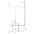
- FIG. 3 is a side sectional view illustrating the inside of the electrical connection box 1.
- FIG. 4 is an explanatory diagram showing a state in which two electric components 40 are connected by a bus bar 5. 3 and 4 are shown with the opening side of the upper case 21 as the upper side.
- FIG. 3 is a schematic view of a side cross section parallel to the longitudinal direction of the housing 2.
- FIG. 4 is a perspective view showing a state in which the fuse 42 and the relay 41 are connected by the bus bar 5 with the upper case 21 removed.
- the electric junction box 1 includes a plurality of electric components 40 including a fuse 42 and a relay 41, a bus bar 5, a second bus bar 7, a third bus bar 8, a temperature sensor 6, a heat radiating member 31, and a second heat radiating member 32.
- a plurality of electric components 40 including a fuse 42 and a relay 41, a bus bar 5 connecting the fuse 42 and the relay 41, a second bus bar 7, a temperature sensor 6, and a heat radiating member 31 are uppers constituting the housing 2 of the electric connection box 1. It is housed inside the case 21.
- the second heat radiating member 32 is attached to the outer surface of the upper case 21.
- the relay 41 forms a rectangular parallelepiped. On one side surface of the relay 41, relay terminals 411 on the positive electrode side and the relay terminal 411 on the negative electrode side are provided side by side. An insulating wall is provided between the relay terminals 411 on the positive electrode side and the negative electrode side so as to project from the one side surface.
- the fuse 42 forms a rectangular parallelepiped. Fuse terminals 421 on the positive electrode side and the negative electrode side are provided on one side surface of the fuse 42 and the other side surface facing the one side surface, respectively. As shown in FIGS. 3 and 4, the fuse 42 and the relay 41 are arranged adjacent to each other with their side surfaces facing each other.
- the fuse 42 is located and connected to the positive electrode side of the power storage device 100 with respect to the relay 41 (see FIG. 1), and the fuse terminal 421 on the positive electrode side of the fuse 42 is connected to the power storage device 100 via the third bus bar 8. It is connected to the positive electrode of.
- the fuse terminal 421 on the negative electrode side of the fuse 42 and the relay terminal 411 on the positive electrode side of the relay 41 are connected by a bus bar 5.
- the relay terminal 411 on the negative electrode side of the relay 41 is connected to the vehicle-mounted load 101 via the second bus bar 7.
- the bus bar 5 is made of a plate member having a plurality of bent portions, and is made of a metal having high conductivity and heat transfer coefficient by copper or a copper alloy or the like.
- the bus bar 5 includes a first plate portion 51, a second plate portion 52, and a connecting plate portion 53.
- a relay 41 is mounted on the first plate portion 51, and the relay 41 and the first plate portion 51 of the bus bar 5 are in close contact with each other.
- a fuse terminal 421 on the negative electrode side of the fuse 42 is fastened to the second plate portion 52, and the fuse terminal 421 on the negative electrode side of the fuse 42 and the second plate portion 52 of the bus bar 5 are in close contact with each other.
- the first plate portion 51 and the second plate portion 52 are provided so as to be substantially parallel to each other, and a connecting plate portion 53 is provided between the first plate portion 51 and the second plate portion 52. ..
- the second plate portion 52 to which the fuse terminal 421 is fastened is provided at a position higher than the first plate portion 51 on which the relay 41 is mounted, with the bottom surface of the upper case 21 as a reference. , It is provided so as to absorb the inter-plane distance caused by the difference in height between the first plate portion 51 and the second plate portion 52. Therefore, as shown in FIG. 3, the first plate portion 51, the connecting plate portion 53, and the second plate portion 52 form a crank shape in a side view.
- a first terminal fastening piece 511 bent substantially perpendicular to the first plate portion 51 is provided.
- a relay terminal 411 on the positive electrode side of the relay 41 is fastened to the first terminal fastening piece 511.
- a heat radiating member 31 is provided between the first plate portion 51 of the bus bar 5 and the bottom plate of the upper case 21. That is, the heat radiating member 31 is interposed between the first plate portion 51 and the upper case 21, and is in surface contact with the first plate portion 51 and the upper case 21 respectively. Therefore, a laminated structure is formed by the first plate portion 51 of the bus bar 5, the heat radiating member 31, and the bottom plate of the upper case 21, and the heat generated by the relay 41 and the fuse 42 via the bus bar 5 is efficiently transferred to the upper case. Heat can be dissipated from 21 to the electrical junction box 1 to the outside.
- the heat radiating member 31 is a resin heat radiating sheet having a rectangular sheet shape and having, for example, silicone-based, non-silicone-based or acrylic-based insulating and heat-transmitting properties.
- the heat radiating member 31 may be a graphite sheet whose surface is insulated.
- the area of the heat radiating member 31 is larger than the area of the region (contact region) in close contact with the relay 41 in the first plate portion 51 of the bus bar 5 on which the relay 41 is placed. Therefore, the region (adhesion region) in which the relay 41 and the first plate portion 51 are in close contact with each other and the heat radiating member are surely overlapped with each other in a plan view, and the bus bar 5 and the heat radiating member 31 are laminated to form the bus bar 5 And the heat transfer efficiency by the heat radiating member 31 can be improved.
- the surface width of the connecting plate portion 53 is the first plate portion 51 and the second plate in the extending direction of the bus bar 5, that is, the arrangement direction of the relay 41 and the fuse 42 connected by the bus bar 5. It is smaller than the surface width of the portion 52.
- the surface width of the connecting plate portion 53 can be made smaller than the surface width of the first plate portion 51 and the second plate portion 52. Thermal resistance can be reduced. Therefore, the heat generated by the fuse 42, which is transferred from the second plate portion 52, can be transferred to the connecting plate and the first plate portion 51, and can be dissipated from the heat radiating member 31.
- the fuse 42 and the relay 41 are provided next to each other, and the connecting plate portion 53 is provided between the side surfaces of the facing fuse 42 and the relay 41.
- the side surfaces of the facing fuse 42 and the relay 41 are close to each other, and the distance between the side surfaces of the facing fuse 42 and the relay 41 is, for example, within 5 times the size of the plate thickness of the connecting plate portion 53.
- the fuse 42 and the relay 41 are arranged next to each other.
- the heat radiating member 31 is provided so as to overlap with the first plate portion 51 on which the relay 41 is placed in a plan view. That is, the heat radiating member 31 is provided so as to be biased toward the side where the relay 41 is arranged in the extending direction of the bus bar 5.
- the amount of heat generated by the relay 41 in a unit time is larger than the amount of heat generated by the fuse 42.
- the heat radiating member 31 may be provided so as to overlap the plate portion of the second bus bar 7 connected to the relay terminal 411 on the negative electrode side of the relay 41.
- the plate portion of the second bus bar 7 is a plate portion on which the relay 41 is placed, similarly to the first plate portion 51 of the bus bar 5.
- a second heat radiating member 32 is provided on the outer surface of the bottom plate of the upper case 21. That is, the second heat radiating member 32 is attached to the outer surface of the housing 2 composed of the upper case 21 and the lower case 22.
- the second heat radiating member 32 is a resin heat radiating sheet having a rectangular sheet shape and having, for example, silicone-based, non-silicone-based or acrylic-based insulating and heat-transmitting properties.
- the second heat radiating member 32 may be a graphite sheet.
- the area of the second heat radiating member 32 is larger than the area of the region (contact region) in close contact with the relay 41 in the first plate portion 51 of the bus bar 5 on which the relay 41 is placed.
- a heat radiating member 31 is attached to the inner surface of the bottom plate of the upper case 21, and a second heat radiating member 32 is attached to the outer surface of the bottom plate of the upper case 21.
- a laminated structure was formed by the first plate portion 51 of the bus bar 5, the heat radiating member 31, the bottom plate of the upper case 21, and the second heat radiating member 32, which was generated by the relay 41 and the fuse 42 via the bus bar 5. Heat can be efficiently dissipated from the second heat radiating member 32 to the outside of the electric connection box 1.
- the second heat radiating member 32 is exposed to the outside of the electric connection box 1 and comes into contact with the ambient air of the electric connection box 1 or the chassis to which the electric connection box 1 is attached or other in-vehicle device of the cooling system. , Exchange heat with these chassis, etc. Therefore, the heat generated by the fuse 42 and the relay 41 can be efficiently dissipated to the outside of the electric junction box 1 and the temperature of the electric junction box 1 can be suppressed from rising.
- the second heat radiating member 32 is made of the same material as the heat radiating member 31, and may have the same shape and size. That is, the heat radiating member 31 and the second heat radiating member 32 may be managed as the same part number (part number) at the manufacturing stage of the electrical connection box 1.
- part number part number
- the second heat radiating member 32 has the same shape and size as the heat radiating member 31, the second heat radiating member 32 and the heat radiating member 31 are upper so that the second heat radiating member 32 and the heat radiating member 31 overlap each other in a plan view. It may be attached to the outer surface and the inner surface of the bottom plate of the case 21. By overlapping the second heat radiating member 32 and the heat radiating member 31 in a plan view and attaching them to the bottom plate of the upper case 21, the effect of radiating heat to the outside of the electric connection box 1 can be further improved.
- the first terminal fastening piece 511 of the bus bar 5 is provided with a temperature sensor 6 that detects and outputs a physical quantity related to the temperature of the bus bar 5.
- the temperature sensor 6 is attached to the surface of the first terminal fastening piece 511 opposite to the relay 41. Alternatively, the temperature sensor 6 may be attached to the surface of the first terminal fastening piece 511 on the side of the relay 41.
- the temperature sensor 6 may include, for example, a thermistor such as an NTC thermistor, a PTC thermistor, or a CTR thermistor, or may be a sensor using a thermocouple.
- the temperature sensor 6 is provided on the bus bar 5, and the bus bar 5 is connected to a relay 41 and a fuse 42 adjacent to each other in close proximity to each other. Therefore, the temperature due to the heat generated by the relay 41 and the fuse 42 can be detected by the single temperature sensor 6 provided in the bus bar 5, and the number of the temperature sensors 6 mounted on the electrical junction box 1 can be reduced. , It is possible to reduce the component cost, miniaturization and weight reduction of the electric junction box 1.
- the temperature sensor 6 is provided on the first terminal fastening piece 511, but the temperature sensor 6 is not limited to this.
- the temperature sensor 6 may be attached to the first plate portion 51, the connecting plate portion 53, or the second plate portion 52.
- FIG. 5 is a perspective view of the bus bar 5.
- FIG. 6 is a plan view of the bus bar 5.
- FIG. 7 is a side view of the bus bar 5.
- the bus bar 5 is a plate member having a plurality of bent portions and having high conductivity and heat transfer property, which is formed by bending and punching a sheet metal using copper or a copper alloy as a material.
- the bus bar 5 includes a first plate portion 51, a second plate portion 52, and a connecting plate portion 53 that connects the first plate portion 51 and the second plate portion 52.
- the first plate portion 51 has a rectangular shape in a plan view, and a relay 41 is placed on the surface of the first plate portion 51 (upper surface in FIG. 5).
- a heat radiating member 31 is attached to the back surface of the first plate portion 51 (lower surface in FIG. 5).
- a first terminal fastening piece 511 bent substantially perpendicular to the first plate portion 51 toward the side opposite to the first plate portion 51 is provided.
- the first terminal fastening piece 511 has a rectangular shape, and a first terminal fastening hole 512 for fastening the relay terminal 411 is provided on the peripheral side.
- a bent piece 513 bent substantially perpendicular to the first terminal fastening piece 511 is provided.
- the second plate portion 52 has a rectangular shape in a plan view, and a second terminal fastening hole 521 for fastening the fuse terminal 421 is provided in the central portion.
- a fuse terminal 421 having a rectangular plate shape is placed on the surface of the second plate portion 52 (upper surface in FIG. 5).
- the connecting plate portion 53 has a rectangular shape, is interposed between the first plate portion 51 and the second plate portion 52, and partially forms a heat transfer path from the first plate portion 51 to the second plate portion 52.
- the surface width of the connecting plate portion 53 is (D3) is smaller than the surface width (d1) of the first plate portion 51 and the surface width (d2) of the surface width of the second plate portion 52 (d3 ⁇ d1 and d3 ⁇ d2).
- the extending direction of the bus bar 5 is the arrangement direction of the fuse 42 and the relay 41 connected by the bus bar 5.
- the relay terminal 411 is connected from the second terminal fastening hole 521 to which the fuse terminal 421 is fastened. It may be in the direction toward the first terminal fastening hole 512 to be fastened.
- the connecting plate portion 53 is interposed between the first plate portion 51 and the second plate portion 52, and forms a part of the heat transfer path from the second plate portion 52 to the first plate portion 51.
- the distance of the heat transfer path can be reduced and the heat transfer resistance can be reduced. Therefore, the heat generated from the fuse 42 connected to the second plate portion 52 is efficiently transferred to the first plate portion 51, and the heat is transferred to the first plate portion 51 via the heat radiating member 31 provided so as to be overlapped with the first plate portion 51.
- the heat generated from the fuse 42 can be efficiently dissipated.
- FIG. 8 is a perspective view schematically showing the appearance of the electrical connection box 1 according to the second embodiment.
- FIG. 9 is a side sectional view illustrating the inside of the electrical connection box 1. Similar to the electrical junction box 1 of the first embodiment, the electrical junction box 1 according to the second embodiment has a plurality of electric components 40 including a fuse 42 and a relay 41, a bus bar 5, a second bus bar 7, a third bus bar 8, and a temperature sensor. 6.
- the heat radiating member 31 and the second heat radiating member 32 are included.
- a plurality of electric components 40 including a fuse 42 and a relay 41, a bus bar 5 connecting the fuse 42 and the relay 41, a second bus bar 7, a temperature sensor 6, and a heat radiating member 31 are uppers constituting the housing 2 of the electric connection box 1. It is housed inside the case 21.
- the sheet-shaped heat radiating member 31 is provided with one surface of its own member (heat radiating member 31) opposed to the inner surface of the lower case 22 provided so as to close the opening of the upper case 21, and is provided with one surface of the heat radiating member 31. It is in close contact with the inner surface of the lower case 22.
- the second heat radiating member 32 is attached to the outer surface of the lower case 22.
- the arrangement relationship between the electric component 40 such as the relay 41 and the fuse 42 and the bus bar 5 and the lower case 22 is the same as that of the electric component 40 and the bus bar 5 described in the first embodiment and the upper case 21. It is the same as the arrangement relationship with the bottom plate of.
- a laminated structure is formed by the sheet-shaped heat radiating member 31, the plate-shaped lower case 22, and the sheet-shaped second heat radiating member 32, and the heat generated by the relay 41 and the fuse 42 via the bus bar 5 is efficiently transferred. Heat can be dissipated from the lower case 22 to the electrical connection box 1 to the outside.
- the lower case 22 is interposed between the heat radiating member 31 and the second heat radiating member 32 to form a laminated structure by the heat radiating member 31, the lower case 22 and the second heat radiating member 32.
- the bottom plate of the upper case 21 is interposed between the heat radiating member 31 and the second heat radiating member 32 to form a laminated structure of the heat radiating member 31, the bottom plate of the upper case 21 and the second heat radiating member 32.
- the arrangement of the heat radiating member 31 and the second heat radiating member 32 with respect to the upper case 21 and the lower case 22 constituting the housing 2 is based on the shape and arrangement of the fuse 42, the relay 41, the bus bar 5 and the like provided inside the housing 2.
- the heat radiating member 31 and the second heat radiating member 32 may be provided on the side plate of the upper case 21. That is, the heat radiating member 31 may be provided on the inner surface of the side plate of the upper case 21, and the second heat radiating member 32 may be attached to the outer surface of the side plate of the upper case 21.
Abstract
This electrical connection box is mounted to a vehicle, the electrical connection box comprising: a busbar that electrically and thermally interconnects a plurality of electrical components which are electrically connected to an electrical storage device mounted to the vehicle, or electrically connected to an on-vehicle load; a housing that accommodates the plurality of electrical components and the busbar; and an insulating heat radiation member thermally connected to the busbar and the housing, wherein, at least two of the electrical components among the plurality of electrical components are disposed beside each other and the busbar radiates the heat from the two electrical components through the heat radiation member.
Description
本開示は、電気接続箱に関する。
本出願は、2019年9月26日出願の日本出願第2019-175970号に基づく優先権を主張し、前記日本出願に記載された全ての記載内容を援用するものである。 The present disclosure relates to electrical junction boxes.
This application claims priority based on Japanese Application No. 2019-175970 filed on September 26, 2019, and incorporates all the contents described in the Japanese application.
車載に搭載され、車載バッテリから車内の各車載負荷に電力を供給する電線は、電機接続箱(ジャンクションボックス)に一旦接続され、当該電機接続箱を介して車載負荷夫々に接続される(例えば、特許文献1)。特許文献1の電機接続箱には、リレー及び当該リレーが固定される箱本体を備える。
The electric wires mounted on the vehicle and supplying electric power from the vehicle battery to each vehicle load in the vehicle are once connected to the electric junction box (junction box) and connected to each vehicle load via the electric junction box (for example,). Patent Document 1). The electric connection box of Patent Document 1 includes a relay and a box body to which the relay is fixed.
本開示の一態様に係る電気接続箱は、車両に搭載される電気接続箱であって、前記車両に搭載される蓄電装置又は車載負荷に電気的に接続される複数の電気部品同士を、電気的及び熱的に接続するバスバと、前記複数の電気部品及び前記バスバを収容する筐体と、前記バスバ及び前記筐体と熱的に接続される絶縁性の放熱部材とを備え、前記複数の電気部品における少なくとも2つの電気部品は、隣り合って配置されており、前記バスバは、前記2つの電気部品からの発熱を前記放熱部材を介して放熱する。
The electric junction box according to one aspect of the present disclosure is an electric junction box mounted on a vehicle, and electrically connects a plurality of electric components electrically connected to a power storage device mounted on the vehicle or an in-vehicle load. A plurality of bus bars that are thermally connected to each other, include the plurality of electrical components and a housing that accommodates the bus bars, and an insulating heat radiating member that is thermally connected to the bus bars and the housing. At least two electric components in the electric component are arranged next to each other, and the bus bar dissipates heat generated from the two electric components via the heat radiating member.
[本開示が解決しようとする課題]
電機接続箱に収納されるリレー等の電気部品は、電流が流れることにより発熱するところ、特許文献1の電機接続箱においては、このような電気部品による発熱に対する考慮がされていないという問題点がある。 [Issues to be solved by this disclosure]
Electric parts such as relays housed in an electric connection box generate heat due to the flow of an electric current, but the electric connection box ofPatent Document 1 has a problem that heat generation due to such electric parts is not taken into consideration. is there.
電機接続箱に収納されるリレー等の電気部品は、電流が流れることにより発熱するところ、特許文献1の電機接続箱においては、このような電気部品による発熱に対する考慮がされていないという問題点がある。 [Issues to be solved by this disclosure]
Electric parts such as relays housed in an electric connection box generate heat due to the flow of an electric current, but the electric connection box of
本開示は、電気接続箱に収納される電気部品による発熱を、効率的に放熱することができる電気接続箱を提供することを目的とする。
An object of the present disclosure is to provide an electric junction box capable of efficiently dissipating heat generated by electrical parts housed in the electrical junction box.
[本開示の効果]
本開示の一態様によれば、電気接続箱に収納される電気部品による発熱を効率的に放熱する電気接続箱を提供することができる。 [Effect of the present disclosure]
According to one aspect of the present disclosure, it is possible to provide an electrical junction box that efficiently dissipates heat generated by electrical components housed in the electrical junction box.
[本開示の実施形態の説明]
最初に本開示の実施態様を列挙して説明する。また、以下に記載する実施形態の少なくとも一部を任意に組み合わせてもよい。 [Explanation of Embodiments of the present disclosure]
First, embodiments of the present disclosure will be listed and described. In addition, at least a part of the embodiments described below may be arbitrarily combined.
最初に本開示の実施態様を列挙して説明する。また、以下に記載する実施形態の少なくとも一部を任意に組み合わせてもよい。 [Explanation of Embodiments of the present disclosure]
First, embodiments of the present disclosure will be listed and described. In addition, at least a part of the embodiments described below may be arbitrarily combined.
(1)本開示の一態様に係る電気接続箱は、車両に搭載される電気接続箱であって、前記車両に搭載される蓄電装置又は車載負荷に電気的に接続される複数の電気部品同士を、電気的及び熱的に接続するバスバと、前記複数の電気部品及び前記バスバを収容する筐体と、前記バスバ及び前記筐体と熱的に接続される絶縁性の放熱部材とを備え、前記複数の電気部品における少なくとも2つの電気部品は、隣り合って配置されており、前記バスバは、前記2つの電気部品からの発熱を前記放熱部材を介して放熱する。
(1) The electric junction box according to one aspect of the present disclosure is an electric junction box mounted on a vehicle, and a plurality of electric components electrically connected to a power storage device mounted on the vehicle or an in-vehicle load. A bus bar that is electrically and thermally connected, a housing that houses the plurality of electrical components and the bus bar, and an insulating heat radiating member that is thermally connected to the bus bar and the housing. At least two electric components in the plurality of electric components are arranged next to each other, and the bus bar dissipates heat generated from the two electric components via the heat radiating member.
本態様にあたっては、放熱対象となる2つの電気部品は、隣り合って配置されているため、これら2つの電気部品を接続するバスバの延在方向の長さを短くし、バスバにおける熱抵抗を低減させることができる。当該2つの電気部品にて発生した熱は、これら電気部品を接続するバスバに効率的に伝わり、当該バスバに熱的に接続された放熱部材及び筐体を介して電気接続箱の外部に放熱される。従って、隣り合って配置された複数の電気部品からの発熱を、単一のバスバ及び放熱部材によって効率的に放熱することができる。
In this embodiment, since the two electric components to be heat-dissipated are arranged next to each other, the length of the bus bar connecting these two electric components in the extending direction is shortened, and the thermal resistance in the bus bar is reduced. Can be made to. The heat generated by the two electric components is efficiently transferred to the bus bar connecting these electric components, and is dissipated to the outside of the electric junction box via the heat radiating member and the housing thermally connected to the bus bar. To. Therefore, heat generated from a plurality of electric components arranged adjacent to each other can be efficiently dissipated by a single bus bar and a heat radiating member.
(2)本開示の一態様に係る電気接続箱は、前記バスバは、前記2つの電気部品における少なくともいずれかの電気部品に密着する第1板部を含み、前記いずれかの電気部品、前記バスバの前記第1板部、前記放熱部材及び、前記放熱部材が貼付けられた前記筐体の部分により、積層構造が形成される。
(2) In the electrical junction box according to one aspect of the present disclosure, the bus bar includes a first plate portion that is in close contact with at least one of the two electrical components, and the bus bar is one of the electrical components. A laminated structure is formed by the first plate portion, the heat radiating member, and the housing portion to which the heat radiating member is attached.
本態様にあたっては、バスバは、いずれかの電気部品に密着する第1板部を含み、当該ずれかの電気部品、バスバの第1板部、放熱部材及び、放熱部材が貼付けられた筐体の部分により、互いに面接触する積層構造が形成される。2つの電気部品は隣り合って配置されているため、当該2つの電気部品からの発熱は、バスバの第1板部等を含む積層構造により効率的に電気接続箱の筐体に伝熱され、当該発熱を電気接続箱の外部に効率的に放熱することができる。
In this embodiment, the bus bar includes a first plate portion that is in close contact with any of the electric components, and the electric component of the deviation, the first plate portion of the bus bar, the heat radiating member, and the housing to which the heat radiating member is attached. The portions form a laminated structure that is in surface contact with each other. Since the two electric parts are arranged next to each other, the heat generated from the two electric parts is efficiently transferred to the housing of the electric junction box by the laminated structure including the first plate portion of the bus bar. The heat generation can be efficiently dissipated to the outside of the electric junction box.
(3)本開示の一態様に係る電気接続箱は、前記放熱部材は、シート状を成し、前記放熱部材の面積は、前記第1板部における前記いずれかの電気部品と密着している領域の面積よりも広い。
(3) In the electric junction box according to one aspect of the present disclosure, the heat radiating member has a sheet shape, and the area of the heat radiating member is in close contact with any of the electric parts in the first plate portion. Larger than the area of the area.
本態様にあたっては、シート状を成す放熱部材の面積は、第1板部における電気部品と密着している領域の面積よりも広いため、当該密着している領域と放熱部材とを、平面視にて確実に重なり合わせてバスバと放熱部材とを積層することができる。
In this embodiment, since the area of the heat radiating member forming the sheet shape is larger than the area of the area in close contact with the electric component in the first plate portion, the contact area and the heat radiating member are viewed in a plan view. The bus bar and the heat radiating member can be laminated with each other without fail.
(4)本開示の一態様に係る電気接続箱は、前記筐体の外面に設けられる第2放熱部材を備え、前記放熱部材、前記放熱部材が貼付けられた前記筐体の部分及び、前記第2放熱部材により、積層構造が形成される。
(4) The electric connection box according to one aspect of the present disclosure includes a second heat radiating member provided on the outer surface of the housing, the heat radiating member, a portion of the housing to which the heat radiating member is attached, and the first. 2 The heat radiating member forms a laminated structure.
本態様にあたっては、放熱部材、放熱部材が貼付けられた筐体の部分及び、第2放熱部材により、互いに面接触する積層構造が形成されるため、第2放熱部材により、筐体の外側に位置する周辺空気等の冷熱源との熱交換を促進することができる。従って、隣り合って配置された2つの電気部品による発熱を、更に効率的に電気接続箱の外部に放熱することができる。
In this embodiment, since the heat radiating member, the portion of the housing to which the heat radiating member is attached, and the second heat radiating member form a laminated structure in which they are in surface contact with each other, the second heat radiating member is positioned outside the housing. It is possible to promote heat exchange with a cold heat source such as ambient air. Therefore, the heat generated by the two electric components arranged next to each other can be more efficiently dissipated to the outside of the electric junction box.
(5)本開示の一態様に係る電気接続箱は、前記放熱部材及び前記第2放熱部材は、同一の素材及び形状を成す。
(5) In the electric junction box according to one aspect of the present disclosure, the heat radiating member and the second heat radiating member have the same material and shape.
本態様にあたっては、放熱部材及び第2放熱部材は、同一の素材及び形状を成すため、同一部品(品番)として取り扱われるものとなり、製造段階において、放熱部材及び第2放熱部材を筐体に取付ける際の誤組み防止を図ることができる。
In this embodiment, since the heat radiating member and the second heat radiating member have the same material and shape, they are treated as the same part (product number), and the heat radiating member and the second heat radiating member are attached to the housing at the manufacturing stage. It is possible to prevent misassembly at the time.
(6)本開示の一態様に係る電気接続箱は、前記バスバは、前記2つの電気部品におけるいずれかの電気部品に密着する第1板部と、他方の電気部品に密着する第2板部と、前記第1板部と前記第2板部との間に介在する連結板部とを含み、前記バスバの延在方向における前記連結板部の面幅は、前記第1板部及び前記第2板部の面幅よりも小さい。
(6) In the electric junction box according to one aspect of the present disclosure, the bus bar has a first plate portion that is in close contact with one of the two electric components and a second plate portion that is in close contact with the other electric component. And the connecting plate portion interposed between the first plate portion and the second plate portion, and the surface width of the connecting plate portion in the extending direction of the bus bar is the first plate portion and the first plate portion. It is smaller than the surface width of the two plates.
本態様にあたっては、バスバは、2つの電気部品夫々に密着する第1板部及び第2板部を含むため、これら第1板部及び第2板部によって電気部品からの発熱をバスバに効率的に伝えることができる。第1板部及び第2板部の間に介在する連結板部の面幅は、第1板部及び第2板部のいずれかの面幅よりも小さいため、バスバの熱抵抗を低減させることができる。従って、これら電気部品からの発熱を効率的に放熱部材に伝熱させて電気接続箱の外部に放熱することができる。
In this embodiment, since the bus bar includes a first plate portion and a second plate portion that are in close contact with each of the two electric components, the heat generated from the electric components is efficiently transferred to the bus bar by the first plate portion and the second plate portion. Can be told to. Since the surface width of the connecting plate portion interposed between the first plate portion and the second plate portion is smaller than the surface width of either the first plate portion or the second plate portion, the thermal resistance of the bus bar should be reduced. Can be done. Therefore, the heat generated from these electric components can be efficiently transferred to the heat radiating member and radiated to the outside of the electric junction box.
(7)本開示の一態様に係る電気接続箱は、前記蓄電装置から前記車載負荷に電力が供給された際の前記2つの電気部品夫々の単位時間あたりの発熱量は、異なり、前記放熱部材は、前記2つの電気部品の内の発熱量が多い電気部品の側に設けられている。
(7) In the electric junction box according to one aspect of the present disclosure, the amount of heat generated per unit time of each of the two electric components when power is supplied from the power storage device to the vehicle-mounted load is different, and the heat radiation member. Is provided on the side of the electric component that generates a large amount of heat among the two electric components.
本態様にあたっては、放熱部材は、2つの電気部品の内の発熱量が多い電気部品の側に設けられているため、2つの電気部品からバスバに伝熱された発熱を、当該放熱部材を介して効率的に電気接続箱の外部に放熱すると共に、放熱部材のサイズを、発熱量が多い電気部品に対応としたサイズにして放熱部材が大きくなることを抑制し、電気接続箱の部品コストの低減、小型化及び軽量化を図ることができる。
In this embodiment, since the heat radiating member is provided on the side of the electric component that generates a large amount of heat among the two electric components, the heat generated from the two electric components to the bus bar is transferred to the bus bar via the heat radiating member. Efficiently dissipates heat to the outside of the electric junction box, and the size of the heat dissipation member is made to correspond to the electric parts that generate a large amount of heat to prevent the heat dissipation member from becoming large. It is possible to reduce the size, size and weight.
(8)本開示の一態様に係る電気接続箱は、前記2つの電気部品は、リレー及びヒューズである。
(8) In the electrical junction box according to one aspect of the present disclosure, the two electrical components are a relay and a fuse.
本態様にあたっては、リレー及びヒューズを隣り合わせて配置することにより、当該リレー及びヒューズからの発熱を効率的に電気接続箱の外部に放熱することができる。
In this embodiment, by arranging the relay and the fuse next to each other, the heat generated from the relay and the fuse can be efficiently dissipated to the outside of the electric junction box.
(9)本開示の一態様に係る電気接続箱は、前記2つの電気部品による発熱を検知する温度センサを備え、前記温度センサは、前記バスバ上に設けられている。
(9) The electric junction box according to one aspect of the present disclosure includes a temperature sensor that detects heat generated by the two electric components, and the temperature sensor is provided on the bus bar.
本態様にあたっては、温度センサはバスバ上に設けられているので、隣り合って配置される電気部品からの発熱を単一の温度センサで検知することができ、電気接続箱に実装される温度センサの個数を低減させ、電気接続箱の部品コストの低減、小型化及び軽量化を図ることができる。
In this embodiment, since the temperature sensor is provided on the bus bar, the heat generated from the electric components arranged adjacent to each other can be detected by a single temperature sensor, and the temperature sensor mounted on the electric junction box. It is possible to reduce the number of parts, reduce the cost of parts of the electric junction box, and reduce the size and weight.
[本開示の実施形態の詳細]
本開示の実施態様に係る電気接続箱1の具体例を以下に図面を参照しつつ説明する。なお、本開示はこれらの例示に限定されるものではなく、請求の範囲によって示され、請求の範囲と均等の意味および範囲内でのすべての変更が含まれることが意図される。 [Details of Embodiments of the present disclosure]
A specific example of theelectrical connection box 1 according to the embodiment of the present disclosure will be described below with reference to the drawings. It should be noted that the present disclosure is not limited to these examples, and is indicated by the scope of claims, and is intended to include all modifications within the meaning and scope equivalent to the scope of claims.
本開示の実施態様に係る電気接続箱1の具体例を以下に図面を参照しつつ説明する。なお、本開示はこれらの例示に限定されるものではなく、請求の範囲によって示され、請求の範囲と均等の意味および範囲内でのすべての変更が含まれることが意図される。 [Details of Embodiments of the present disclosure]
A specific example of the
(実施形態1)
図1は、実施形態1に係る電気接続箱1が搭載された車両Cを示す概略図である。本実施形態における電気接続箱1は、車両Cに搭載され、同様に車両Cに搭載される蓄電装置100と車載負荷101との間に介在して設けられる。蓄電装置100及び車載負荷101は、電気接続箱1を介して、電線102により電気的に接続されている。 (Embodiment 1)
FIG. 1 is a schematic view showing a vehicle C on which theelectrical connection box 1 according to the first embodiment is mounted. The electric junction box 1 in the present embodiment is mounted on the vehicle C, and is provided between the power storage device 100 mounted on the vehicle C and the vehicle-mounted load 101. The power storage device 100 and the vehicle-mounted load 101 are electrically connected by an electric wire 102 via the electric connection box 1.
図1は、実施形態1に係る電気接続箱1が搭載された車両Cを示す概略図である。本実施形態における電気接続箱1は、車両Cに搭載され、同様に車両Cに搭載される蓄電装置100と車載負荷101との間に介在して設けられる。蓄電装置100及び車載負荷101は、電気接続箱1を介して、電線102により電気的に接続されている。 (Embodiment 1)
FIG. 1 is a schematic view showing a vehicle C on which the
本実施形態にて、車載負荷101は一つとして記載してあるが、車載負荷101の個数は単数に限定されない。車両Cに搭載される車載負荷101は、複数であってもよく、電気接続箱1と、複数の車載負荷101との間に分岐部を設け、当該分岐部により蓄電装置100の正極に接続される電線102を分岐し、分岐した電線102を複数の車載負荷101夫々に接続するものであってもよい。
In the present embodiment, the vehicle-mounted load 101 is described as one, but the number of vehicle-mounted loads 101 is not limited to a single number. The number of vehicle-mounted loads 101 mounted on the vehicle C may be plural, and a branch portion is provided between the electric connection box 1 and the plurality of vehicle-mounted loads 101, and the branch portion is connected to the positive electrode of the power storage device 100. The electric wire 102 may be branched, and the branched electric wire 102 may be connected to each of the plurality of vehicle-mounted loads 101.
本実施形態にて、電気接続箱1は蓄電装置100の正極側に接続してあるが、これに限定されない。電気接続箱1は蓄電装置100の負極側に接続するものであってもよい。又は、電気接続箱1は蓄電装置100の正極側及び負極側の夫々に接続されるものであってもよい。
In the present embodiment, the electric junction box 1 is connected to the positive electrode side of the power storage device 100, but the present invention is not limited to this. The electric junction box 1 may be connected to the negative electrode side of the power storage device 100. Alternatively, the electric junction box 1 may be connected to the positive electrode side and the negative electrode side of the power storage device 100, respectively.
蓄電装置100は、例えば、鉛バッテリ又は、リチウムイオン電池等のEV(Electric Vehicle)用の高圧バッテリである。
The power storage device 100 is, for example, a high-pressure battery for EV (Electric Vehicle) such as a lead battery or a lithium ion battery.
電気接続箱1は、電気部品40を収納する。電気部品40は、例えばヒューズ42、リレー41を含む。リレー41は、機械式リレー、又は半導体リレーであってもよい。電気部品40に含まれるヒューズ42及びリレー41は、バスバにより接続され、直列回路を構成する。リレー41と車載負荷101とは、第2バスバ7を介して接続される。ヒューズ42と蓄電装置100とは、第3バスバ8を介して接続される。リレー41は、車両Cに搭載される電力制御系のECU(図示せず)と信号線により通信可能に接続され、当該ECUから出力される信号に応じて、オン又はオフにされる。
The electrical junction box 1 stores the electrical components 40. The electric component 40 includes, for example, a fuse 42 and a relay 41. The relay 41 may be a mechanical relay or a semiconductor relay. The fuse 42 and the relay 41 included in the electric component 40 are connected by a bus bar to form a series circuit. The relay 41 and the vehicle-mounted load 101 are connected via the second bus bar 7. The fuse 42 and the power storage device 100 are connected via a third bus bar 8. The relay 41 is communicably connected to an ECU (not shown) of the power control system mounted on the vehicle C by a signal line, and is turned on or off according to a signal output from the ECU.
図2は、電気接続箱1の外観を略示した斜視図である。電気接続箱1は、外郭を成す筐体2を備える。筐体2は、絶縁性の樹脂製による直方体を成し、アッパケース21及びロワケース22を含む。筐体2は、例えば放熱性ポリプロピレン、放熱ポリアミド樹脂等による放熱性樹脂製であることが望ましい。
FIG. 2 is a perspective view illustrating the appearance of the electrical connection box 1. The electrical junction box 1 includes a housing 2 forming an outer shell. The housing 2 is a rectangular parallelepiped made of an insulating resin, and includes an upper case 21 and a lower case 22. It is desirable that the housing 2 is made of a heat-dissipating resin such as heat-dissipating polypropylene or heat-dissipating polyamide resin.
アッパケース21は、開口部を有する箱体を成す。アッパケース21の内側には、例えば当該アッパケース21の内壁を構成する固定部材(図示せず)が設けられている。当該固定部材によって、リレー41及びヒューズ42を含む電気部品40は、アッパケース21の内部に固定される。
The upper case 21 forms a box body having an opening. Inside the upper case 21, for example, a fixing member (not shown) constituting the inner wall of the upper case 21 is provided. The electric component 40 including the relay 41 and the fuse 42 is fixed to the inside of the upper case 21 by the fixing member.
ロワケース22は、例えば板状又は皿状の蓋体を成し、アッパケース21の開口部を塞ぐように設けられる。
The lower case 22 forms, for example, a plate-shaped or dish-shaped lid, and is provided so as to close the opening of the upper case 21.
アッパケース21の開口部にロワケース22が係合することにより、電気接続箱1の外郭を成す筐体2が構成される。このように構成される電気接続箱1は、例えば、蓄電装置100の近傍に載置される。
By engaging the lower case 22 with the opening of the upper case 21, the housing 2 forming the outer shell of the electrical connection box 1 is configured. The electrical connection box 1 configured in this way is placed in the vicinity of the power storage device 100, for example.
図3は、電気接続箱1の内部を略示する側断面図である。図4は、2つの電気部品40がバスバ5により接続された状態を示す説明図である。図3及び図4は、アッパケース21の開口部側を上側として図示したものである。図3は、筐体2の長手方向と平行となる側断面を略示したものである。図4は、ヒューズ42及びリレー41がバスバ5により接続された状態を、アッパケース21を外した状態にて見た斜視図である。
FIG. 3 is a side sectional view illustrating the inside of the electrical connection box 1. FIG. 4 is an explanatory diagram showing a state in which two electric components 40 are connected by a bus bar 5. 3 and 4 are shown with the opening side of the upper case 21 as the upper side. FIG. 3 is a schematic view of a side cross section parallel to the longitudinal direction of the housing 2. FIG. 4 is a perspective view showing a state in which the fuse 42 and the relay 41 are connected by the bus bar 5 with the upper case 21 removed.
電気接続箱1は、ヒューズ42及びリレー41を含む複数の電気部品40、バスバ5、第2バスバ7、第3バスバ8、温度センサ6、放熱部材31及び第2放熱部材32を含む。ヒューズ42及びリレー41を含む複数の電気部品40、ヒューズ42及びリレー41を接続するバスバ5、第2バスバ7、温度センサ6及び放熱部材31は、電気接続箱1の筐体2を構成するアッパケース21の内部に収納されている。第2放熱部材32は、アッパケース21の外面に貼付けられている。
The electric junction box 1 includes a plurality of electric components 40 including a fuse 42 and a relay 41, a bus bar 5, a second bus bar 7, a third bus bar 8, a temperature sensor 6, a heat radiating member 31, and a second heat radiating member 32. A plurality of electric components 40 including a fuse 42 and a relay 41, a bus bar 5 connecting the fuse 42 and the relay 41, a second bus bar 7, a temperature sensor 6, and a heat radiating member 31 are uppers constituting the housing 2 of the electric connection box 1. It is housed inside the case 21. The second heat radiating member 32 is attached to the outer surface of the upper case 21.
リレー41は、直方体を成す。リレー41の一側面には、正極側及び負極側のリレー端子411夫々が、並んで設けられている。正極側及び負極側のリレー端子411との間には、絶縁壁が、当該一側面から突出して設けられている。
The relay 41 forms a rectangular parallelepiped. On one side surface of the relay 41, relay terminals 411 on the positive electrode side and the relay terminal 411 on the negative electrode side are provided side by side. An insulating wall is provided between the relay terminals 411 on the positive electrode side and the negative electrode side so as to project from the one side surface.
ヒューズ42は、直方体を成す。ヒューズ42の一側面及び一側面に対向する他側面には、正極側及び負極側のヒューズ端子421夫々が、設けられている。図3及び図4に示すとおり、ヒューズ42及びリレー41は、互いの側面を対向させ、隣り合って配置されている。
The fuse 42 forms a rectangular parallelepiped. Fuse terminals 421 on the positive electrode side and the negative electrode side are provided on one side surface of the fuse 42 and the other side surface facing the one side surface, respectively. As shown in FIGS. 3 and 4, the fuse 42 and the relay 41 are arranged adjacent to each other with their side surfaces facing each other.
ヒューズ42は、リレー41よりも蓄電装置100の正極の側に位置して接続されており(図1参照)、ヒューズ42の正極側のヒューズ端子421は、第3バスバ8を介して蓄電装置100の正極と接続されている。ヒューズ42の負極側のヒューズ端子421と、リレー41の正極側のリレー端子411とは、バスバ5により接続されている。リレー41の負極側のリレー端子411は、第2バスバ7を介して車載負荷101と接続されている。
The fuse 42 is located and connected to the positive electrode side of the power storage device 100 with respect to the relay 41 (see FIG. 1), and the fuse terminal 421 on the positive electrode side of the fuse 42 is connected to the power storage device 100 via the third bus bar 8. It is connected to the positive electrode of. The fuse terminal 421 on the negative electrode side of the fuse 42 and the relay terminal 411 on the positive electrode side of the relay 41 are connected by a bus bar 5. The relay terminal 411 on the negative electrode side of the relay 41 is connected to the vehicle-mounted load 101 via the second bus bar 7.
バスバ5は、複数の折り曲げ部を有する板部材により構成され、銅又は銅合金等による導電率及び熱伝達率が高い金属製である。バスバ5は、第1板部51、第2板部52及び連結板部53を含む。
The bus bar 5 is made of a plate member having a plurality of bent portions, and is made of a metal having high conductivity and heat transfer coefficient by copper or a copper alloy or the like. The bus bar 5 includes a first plate portion 51, a second plate portion 52, and a connecting plate portion 53.
第1板部51には、リレー41が載置され、リレー41とバスバ5の第1板部51とは、密着する。第2板部52には、ヒューズ42の負極側のヒューズ端子421が締結され、ヒューズ42の負極側のヒューズ端子421と、バスバ5の第2板部52とは、密着する。このようにリレー41及びヒューズ42と、バスバ5とが密着することにより、リレー41及びヒューズ42にて発生した熱は、バスバ5に伝熱される。
A relay 41 is mounted on the first plate portion 51, and the relay 41 and the first plate portion 51 of the bus bar 5 are in close contact with each other. A fuse terminal 421 on the negative electrode side of the fuse 42 is fastened to the second plate portion 52, and the fuse terminal 421 on the negative electrode side of the fuse 42 and the second plate portion 52 of the bus bar 5 are in close contact with each other. When the relay 41 and the fuse 42 and the bus bar 5 are in close contact with each other in this way, the heat generated by the relay 41 and the fuse 42 is transferred to the bus bar 5.
第1板部51と第2板部52とは略平行となるように設けられており、第1板部51と第2板部52との間には、連結板部53が設けられている。アッパケース21の底面を基準として、ヒューズ端子421が締結された第2板部52は、リレー41が載置された第1板部51よりも高い位置に設けられており、連結板部53は、第1板部51及び第2板部52の高さ違いにより生じる面間距離を吸収するように設けられている。従って、図3に示すごとく、第1板部51、連結板部53及び第2板部52により側面視にてクランク形状を成す。
The first plate portion 51 and the second plate portion 52 are provided so as to be substantially parallel to each other, and a connecting plate portion 53 is provided between the first plate portion 51 and the second plate portion 52. .. The second plate portion 52 to which the fuse terminal 421 is fastened is provided at a position higher than the first plate portion 51 on which the relay 41 is mounted, with the bottom surface of the upper case 21 as a reference. , It is provided so as to absorb the inter-plane distance caused by the difference in height between the first plate portion 51 and the second plate portion 52. Therefore, as shown in FIG. 3, the first plate portion 51, the connecting plate portion 53, and the second plate portion 52 form a crank shape in a side view.
第1板部51の端部には、第1板部51に対し略垂直に折り曲げられた第1端子締結片511が、設けられている。第1端子締結片511には、リレー41の正極側のリレー端子411が、締結されている。
At the end of the first plate portion 51, a first terminal fastening piece 511 bent substantially perpendicular to the first plate portion 51 is provided. A relay terminal 411 on the positive electrode side of the relay 41 is fastened to the first terminal fastening piece 511.
バスバ5の第1板部51と、アッパケース21の底板との間には、放熱部材31が設けられている。すなわち、放熱部材31は、第1板部51とアッパケース21との間に介在し、第1板部51及びアッパケース21夫々と面接触している。従って、バスバ5の第1板部51、放熱部材31及びアッパケース21の底板により、積層構造が形成され、バスバ5を介して、リレー41及びヒューズ42にて発生した熱を効率的にアッパケース21から電気接続箱1に外部に放熱することができる。
A heat radiating member 31 is provided between the first plate portion 51 of the bus bar 5 and the bottom plate of the upper case 21. That is, the heat radiating member 31 is interposed between the first plate portion 51 and the upper case 21, and is in surface contact with the first plate portion 51 and the upper case 21 respectively. Therefore, a laminated structure is formed by the first plate portion 51 of the bus bar 5, the heat radiating member 31, and the bottom plate of the upper case 21, and the heat generated by the relay 41 and the fuse 42 via the bus bar 5 is efficiently transferred to the upper case. Heat can be dissipated from 21 to the electrical junction box 1 to the outside.
放熱部材31は、矩形のシート状を成し、例えばシリコーン系、非シリコーン系又はアクリル系の絶縁性及び伝熱性を有する樹脂製の放熱シートである。又は、放熱部材31は、表面が絶縁処理されたグラファイトシートであってもよい。
The heat radiating member 31 is a resin heat radiating sheet having a rectangular sheet shape and having, for example, silicone-based, non-silicone-based or acrylic-based insulating and heat-transmitting properties. Alternatively, the heat radiating member 31 may be a graphite sheet whose surface is insulated.
放熱部材31の面積は、リレー41が載置されるバスバ5の第1板部51における、リレー41と密着している領域(密着領域)の面積よりも広い。従って、リレー41と第1板部51とが密着している領域(密着領域)と、放熱部材とを、平面視にて確実に重なり合わせてバスバ5と放熱部材31とを積層させ、バスバ5及び放熱部材31による伝熱効率を向上させることができる。
The area of the heat radiating member 31 is larger than the area of the region (contact region) in close contact with the relay 41 in the first plate portion 51 of the bus bar 5 on which the relay 41 is placed. Therefore, the region (adhesion region) in which the relay 41 and the first plate portion 51 are in close contact with each other and the heat radiating member are surely overlapped with each other in a plan view, and the bus bar 5 and the heat radiating member 31 are laminated to form the bus bar 5 And the heat transfer efficiency by the heat radiating member 31 can be improved.
詳細は、別途説明するが、バスバ5の延在方向、すなわちバスバ5によって接続されるリレー41及びヒューズ42の配置方向において、連結板部53の面幅は、第1板部51及び第2板部52の面幅よりも小さい。ヒューズ42及びリレー41を隣り合って設け、近接させることにより、連結板部53の面幅を、第1板部51及び第2板部52の面幅よりも小さくすることができ、バスバ5の熱抵抗を低減させることができる。従って、第2板部52から伝熱されるヒューズ42の発熱を、連結板及び第1板部51に介して伝熱し、放熱部材31から放熱することができる。
Although the details will be described separately, the surface width of the connecting plate portion 53 is the first plate portion 51 and the second plate in the extending direction of the bus bar 5, that is, the arrangement direction of the relay 41 and the fuse 42 connected by the bus bar 5. It is smaller than the surface width of the portion 52. By providing the fuse 42 and the relay 41 next to each other and bringing them close to each other, the surface width of the connecting plate portion 53 can be made smaller than the surface width of the first plate portion 51 and the second plate portion 52. Thermal resistance can be reduced. Therefore, the heat generated by the fuse 42, which is transferred from the second plate portion 52, can be transferred to the connecting plate and the first plate portion 51, and can be dissipated from the heat radiating member 31.
ヒューズ42及びリレー41は隣り合って設けられており、連結板部53は、対向するヒューズ42及びリレー41の側面の間に設けられている。対向するヒューズ42及びリレー41の側面同士は近接しており、対向するヒューズ42及びリレー41の側面による面間距離は、連結板部53の板厚の大きさの例えば5倍以内となるように、ヒューズ42及びリレー41は隣り合って配置されている。このように対向するヒューズ42及びリレー41の側面同士を近接させ、対向する当該側面の間に連結板部53を設けることにより、ヒューズ42及びリレー41の側面から発せられた熱量を、連結板部53を介して放熱部材31に伝熱して、放熱効率を更に向上させることができる。
The fuse 42 and the relay 41 are provided next to each other, and the connecting plate portion 53 is provided between the side surfaces of the facing fuse 42 and the relay 41. The side surfaces of the facing fuse 42 and the relay 41 are close to each other, and the distance between the side surfaces of the facing fuse 42 and the relay 41 is, for example, within 5 times the size of the plate thickness of the connecting plate portion 53. , The fuse 42 and the relay 41 are arranged next to each other. By bringing the side surfaces of the fuse 42 and the relay 41 facing each other close to each other and providing the connecting plate portion 53 between the facing side surfaces, the amount of heat generated from the side surfaces of the fuse 42 and the relay 41 can be transferred to the connecting plate portion. Heat can be transferred to the heat radiating member 31 via the 53 to further improve the heat radiating efficiency.
放熱部材31は、リレー41が載置される第1板部51と、平面視にて重ならせて設けられている。すなわち、放熱部材31は、バスバ5の延在方向において、リレー41が配置されている側に偏倚させて設けられている。蓄電装置100から車載負荷101に電力が供給される際、単位時間におけるリレー41の発熱量は、ヒューズ42の発熱量よりも大きい。単位時間における発熱量が大きい電気部品40であるリレー41の側に、放熱部材31を設けることにより、放熱効果を担保しつつ、放熱部材31のサイズが大きくなることを抑制して部品コストの低減、電気接続箱1の小型化及び軽量化を図ることができる。
The heat radiating member 31 is provided so as to overlap with the first plate portion 51 on which the relay 41 is placed in a plan view. That is, the heat radiating member 31 is provided so as to be biased toward the side where the relay 41 is arranged in the extending direction of the bus bar 5. When power is supplied from the power storage device 100 to the vehicle-mounted load 101, the amount of heat generated by the relay 41 in a unit time is larger than the amount of heat generated by the fuse 42. By providing the heat radiating member 31 on the side of the relay 41, which is an electric component 40 that generates a large amount of heat in a unit time, the heat radiating effect is ensured, and the size of the heat radiating member 31 is suppressed from becoming large to reduce the component cost. , The electric junction box 1 can be made smaller and lighter.
放熱部材31は、リレー41の負極側のリレー端子411と接続される第2バスバ7の板部と重ならせて設けられているものであってもよい。第2バスバ7の板部は、バスバ5の第1板部51と同様にリレー41が載置される板部である。放熱部材31を、バスバ5の第1板部51及び第2バスバ7の板部に重ならせて設けることにより、リレー41と放熱部材31との伝熱面積を増加させ、リレー41が発生した熱に対する放熱効率を、更に向上させることができる。
The heat radiating member 31 may be provided so as to overlap the plate portion of the second bus bar 7 connected to the relay terminal 411 on the negative electrode side of the relay 41. The plate portion of the second bus bar 7 is a plate portion on which the relay 41 is placed, similarly to the first plate portion 51 of the bus bar 5. By providing the heat radiating member 31 so as to overlap the plate portions of the first plate portion 51 and the second bus bur 7 of the bus bar 5, the heat transfer area between the relay 41 and the heat radiating member 31 is increased, and the relay 41 is generated. The heat dissipation efficiency with respect to heat can be further improved.
アッパケース21の底板の外面には、第2放熱部材32が設けられている。すなわち、第2放熱部材32は、アッパケース21及びロワケース22により構成される筐体2の外面に貼付けられている。第2放熱部材32は、矩形のシート状を成し、例えばシリコーン系、非シリコーン系又はアクリル系の絶縁性及び伝熱性を有する樹脂製の放熱シートである。又は、第2放熱部材32は、グラファイトシートであってもよい。第2放熱部材32の面積は、リレー41が載置されるバスバ5の第1板部51において、リレー41と密着している領域(密着領域)の面積よりも広い。
A second heat radiating member 32 is provided on the outer surface of the bottom plate of the upper case 21. That is, the second heat radiating member 32 is attached to the outer surface of the housing 2 composed of the upper case 21 and the lower case 22. The second heat radiating member 32 is a resin heat radiating sheet having a rectangular sheet shape and having, for example, silicone-based, non-silicone-based or acrylic-based insulating and heat-transmitting properties. Alternatively, the second heat radiating member 32 may be a graphite sheet. The area of the second heat radiating member 32 is larger than the area of the region (contact region) in close contact with the relay 41 in the first plate portion 51 of the bus bar 5 on which the relay 41 is placed.
アッパケース21の底板の内面には、放熱部材31が貼付けされ、アッパケース21の底板の外面には、第2放熱部材32が貼付けられる。これにより、バスバ5の第1板部51、放熱部材31、アッパケース21の底板及び第2放熱部材32により、積層構造が形成され、バスバ5を介して、リレー41及びヒューズ42にて発生した熱を効率的に第2放熱部材32から電気接続箱1の外部に放熱することができる。すなわち、第2放熱部材32は、電気接続箱1の外部に露出しており、電気接続箱1の周辺空気又は、電気接続箱1が取付けられるシャーシ又は冷却系の他の車載機器と接することにより、これらシャーシ等と熱交換する。従って、ヒューズ42及びリレー41が発生した熱を電気接続箱1の外部に効率的に放熱し、電気接続箱1の温度が上昇することを抑制することができる。
A heat radiating member 31 is attached to the inner surface of the bottom plate of the upper case 21, and a second heat radiating member 32 is attached to the outer surface of the bottom plate of the upper case 21. As a result, a laminated structure was formed by the first plate portion 51 of the bus bar 5, the heat radiating member 31, the bottom plate of the upper case 21, and the second heat radiating member 32, which was generated by the relay 41 and the fuse 42 via the bus bar 5. Heat can be efficiently dissipated from the second heat radiating member 32 to the outside of the electric connection box 1. That is, the second heat radiating member 32 is exposed to the outside of the electric connection box 1 and comes into contact with the ambient air of the electric connection box 1 or the chassis to which the electric connection box 1 is attached or other in-vehicle device of the cooling system. , Exchange heat with these chassis, etc. Therefore, the heat generated by the fuse 42 and the relay 41 can be efficiently dissipated to the outside of the electric junction box 1 and the temperature of the electric junction box 1 can be suppressed from rising.
第2放熱部材32は、放熱部材31と同一の素材であり、同一の形状及び大きさのものであってもよい。すなわち、放熱部材31及び第2放熱部材32は、電気接続箱1の製造段階において同一の部品番号(品番)として管理されるものであってもよい。放熱部材31及び第2放熱部材32を同一の部品とすることにより、製造段階において、放熱部材31及び第2放熱部材32を筐体2に取付ける際の誤組み防止を図ると共に、部品共通化による部品コストの低減を図ることができる。
The second heat radiating member 32 is made of the same material as the heat radiating member 31, and may have the same shape and size. That is, the heat radiating member 31 and the second heat radiating member 32 may be managed as the same part number (part number) at the manufacturing stage of the electrical connection box 1. By making the heat radiating member 31 and the second heat radiating member 32 the same parts, it is possible to prevent erroneous assembly when the heat radiating member 31 and the second heat radiating member 32 are attached to the housing 2 at the manufacturing stage, and by standardizing the parts. It is possible to reduce the cost of parts.
第2放熱部材32を、放熱部材31と同一の形状及び大きさとした場合、平面視にて、第2放熱部材32及び放熱部材31が重なり合うように、第2放熱部材32及び放熱部材31をアッパケース21の底板の外面及び内面に貼付けるものであってもよい。平面視にて第2放熱部材32及び放熱部材31を重なり合わせてアッパケース21の底板に貼付けることにより、電気接続箱1の外部に放熱する効果を更に向上させることができる。
When the second heat radiating member 32 has the same shape and size as the heat radiating member 31, the second heat radiating member 32 and the heat radiating member 31 are upper so that the second heat radiating member 32 and the heat radiating member 31 overlap each other in a plan view. It may be attached to the outer surface and the inner surface of the bottom plate of the case 21. By overlapping the second heat radiating member 32 and the heat radiating member 31 in a plan view and attaching them to the bottom plate of the upper case 21, the effect of radiating heat to the outside of the electric connection box 1 can be further improved.
バスバ5の第1端子締結片511には、バスバ5の温度に関する物理量を検出及び出力する温度センサ6が設けられている。温度センサ6は、第1端子締結片511における、リレー41とは反対側の面に貼付けられている。又は、温度センサ6は、第1端子締結片511における、リレー41の側の面に貼付けられているものであってもよい。温度センサ6は、例えばNTCサーミスタ、PTCサーミスタ又はCTRサーミスタ等のサーミスタを含み、又は熱電対を用いたセンサであってもよい。
The first terminal fastening piece 511 of the bus bar 5 is provided with a temperature sensor 6 that detects and outputs a physical quantity related to the temperature of the bus bar 5. The temperature sensor 6 is attached to the surface of the first terminal fastening piece 511 opposite to the relay 41. Alternatively, the temperature sensor 6 may be attached to the surface of the first terminal fastening piece 511 on the side of the relay 41. The temperature sensor 6 may include, for example, a thermistor such as an NTC thermistor, a PTC thermistor, or a CTR thermistor, or may be a sensor using a thermocouple.
温度センサ6は、バスバ5に設けられており、バスバ5は、近接して隣り合うリレー41及びヒューズ42に接続されている。従って、バスバ5に設けられた単一の温度センサ6によって、リレー41及びヒューズ42により発生した熱による温度を検出することができ、電気接続箱1に実装される温度センサ6の個数を低減させ、電気接続箱1の部品コストの低減、小型化及び軽量化を図ることができる。
The temperature sensor 6 is provided on the bus bar 5, and the bus bar 5 is connected to a relay 41 and a fuse 42 adjacent to each other in close proximity to each other. Therefore, the temperature due to the heat generated by the relay 41 and the fuse 42 can be detected by the single temperature sensor 6 provided in the bus bar 5, and the number of the temperature sensors 6 mounted on the electrical junction box 1 can be reduced. , It is possible to reduce the component cost, miniaturization and weight reduction of the electric junction box 1.
温度センサ6は、第1端子締結片511に設けられているとしたが、これに限定されない。温度センサ6は、第1板部51、連結板部53又は第2板部52に貼付けられているものであってもよい。
It is said that the temperature sensor 6 is provided on the first terminal fastening piece 511, but the temperature sensor 6 is not limited to this. The temperature sensor 6 may be attached to the first plate portion 51, the connecting plate portion 53, or the second plate portion 52.
図5は、バスバ5の斜視図である。図6は、バスバ5の平面図である。図7は、バスバ5の側面図である。バスバ5は、上述のとおり銅又は銅合金を素材として板金折り曲げ加工及び打ち抜き加工等により形成され、複数の折り曲げ部を有する導電性及び伝熱性の高い板部材である。バスバ5は、第1板部51、第2板部52及び、第1板部51と第2板部52とを連結する連結板部53を含む。
FIG. 5 is a perspective view of the bus bar 5. FIG. 6 is a plan view of the bus bar 5. FIG. 7 is a side view of the bus bar 5. As described above, the bus bar 5 is a plate member having a plurality of bent portions and having high conductivity and heat transfer property, which is formed by bending and punching a sheet metal using copper or a copper alloy as a material. The bus bar 5 includes a first plate portion 51, a second plate portion 52, and a connecting plate portion 53 that connects the first plate portion 51 and the second plate portion 52.
第1板部51は平面視にて矩形状を成し、第1板部51の表面(図5にて上面)には、リレー41が載置される。第1板部51の裏面(図5にて下面)には、放熱部材31が貼付けられる。
The first plate portion 51 has a rectangular shape in a plan view, and a relay 41 is placed on the surface of the first plate portion 51 (upper surface in FIG. 5). A heat radiating member 31 is attached to the back surface of the first plate portion 51 (lower surface in FIG. 5).
第1板部51の端部には、第1板部51に対し、第1板部51とは反対側に向かって略垂直に折り曲げられた第1端子締結片511が設けられている。第1端子締結片511は矩形状を成し、周縁側には、リレー端子411を締結するための第1端子締結孔512が設けられている。第1端子締結片511の端部には、第1端子締結片511に対し略垂直に折り曲げられた折曲片513が設けられている。
At the end of the first plate portion 51, a first terminal fastening piece 511 bent substantially perpendicular to the first plate portion 51 toward the side opposite to the first plate portion 51 is provided. The first terminal fastening piece 511 has a rectangular shape, and a first terminal fastening hole 512 for fastening the relay terminal 411 is provided on the peripheral side. At the end of the first terminal fastening piece 511, a bent piece 513 bent substantially perpendicular to the first terminal fastening piece 511 is provided.
第2板部52は平面視にて矩形状を成し、中央部には、ヒューズ端子421を締結するための第2端子締結孔521が設けられている。第2板部52の表面(図5にて上面)には、矩形の板状を成すヒューズ端子421が載置される。
The second plate portion 52 has a rectangular shape in a plan view, and a second terminal fastening hole 521 for fastening the fuse terminal 421 is provided in the central portion. A fuse terminal 421 having a rectangular plate shape is placed on the surface of the second plate portion 52 (upper surface in FIG. 5).
連結板部53は、矩形状を成し、第1板部51と第2板部52との間に介在し、第1板部51から第2板部52への伝熱経路の一部を構成する。上述のとおり、ヒューズ端子421が締結される第2板部52と、リレー41が載置される第1板部51との間には、高さ違いによる段差があり、連結板部53は、当該段差により生じる面間距離を吸収するように設けられている。従って、図5における正面視にて、第1板部51、連結板部53及び第2板部52によって、クランク形状が形成される。
The connecting plate portion 53 has a rectangular shape, is interposed between the first plate portion 51 and the second plate portion 52, and partially forms a heat transfer path from the first plate portion 51 to the second plate portion 52. Configure. As described above, there is a step due to the difference in height between the second plate portion 52 to which the fuse terminal 421 is fastened and the first plate portion 51 on which the relay 41 is mounted. It is provided so as to absorb the inter-plane distance caused by the step. Therefore, in the front view in FIG. 5, the crank shape is formed by the first plate portion 51, the connecting plate portion 53, and the second plate portion 52.
バスバ5の延在方向において、第1板部51の面幅をd1、第2板部52の面幅をd2、連結板部53の面幅をd3とした場合、連結板部53の面幅(d3)は、第1板部51の面幅(d1)及び第2板部52の面幅の面幅(d2)よりも小さい(d3<d1及び、d3<d2)。バスバ5の延在方向とは、バスバ5によって接続されるヒューズ42及びリレー41の配置方向であり、バスバ5においては、ヒューズ端子421が締結される第2端子締結孔521から、リレー端子411が締結される第1端子締結孔512に向かう方向であるとしてもよい。
When the surface width of the first plate portion 51 is d1, the surface width of the second plate portion 52 is d2, and the surface width of the connecting plate portion 53 is d3 in the extending direction of the bus bar 5, the surface width of the connecting plate portion 53 is (D3) is smaller than the surface width (d1) of the first plate portion 51 and the surface width (d2) of the surface width of the second plate portion 52 (d3 <d1 and d3 <d2). The extending direction of the bus bar 5 is the arrangement direction of the fuse 42 and the relay 41 connected by the bus bar 5. In the bus bar 5, the relay terminal 411 is connected from the second terminal fastening hole 521 to which the fuse terminal 421 is fastened. It may be in the direction toward the first terminal fastening hole 512 to be fastened.
連結板部53は、第1板部51と第2板部52との間に介在し、第2板部52から第1板部51への伝熱経路の一部を構成するため、当該連結板部53の面幅を、第1板部51及び第2板部52の面幅よりも小さくすることにより、伝熱経路の距離を小さくし、伝熱抵抗を低減させることができる。従って、第2板部52に接続されたヒューズ42からの発熱を効率的に第1板部51に伝熱させ、第1板部51に重ねられて設けられた放熱部材31を介して、当該ヒューズ42からの発熱を効率的に放熱することができる。
The connecting plate portion 53 is interposed between the first plate portion 51 and the second plate portion 52, and forms a part of the heat transfer path from the second plate portion 52 to the first plate portion 51. By making the surface width of the plate portion 53 smaller than the surface width of the first plate portion 51 and the second plate portion 52, the distance of the heat transfer path can be reduced and the heat transfer resistance can be reduced. Therefore, the heat generated from the fuse 42 connected to the second plate portion 52 is efficiently transferred to the first plate portion 51, and the heat is transferred to the first plate portion 51 via the heat radiating member 31 provided so as to be overlapped with the first plate portion 51. The heat generated from the fuse 42 can be efficiently dissipated.
(実施形態2)
図8は、実施形態2に係る電気接続箱1の外観を略示した斜視図である。図9は、電気接続箱1の内部を略示する側断面図である。実施形態2に係る電気接続箱1は、実施形態1の電気接続箱1と同様にヒューズ42及びリレー41を含む複数の電気部品40、バスバ5、第2バスバ7、第3バスバ8、温度センサ6、放熱部材31及び第2放熱部材32を含む。ヒューズ42及びリレー41を含む複数の電気部品40、ヒューズ42及びリレー41を接続するバスバ5、第2バスバ7、温度センサ6及び放熱部材31は、電気接続箱1の筐体2を構成するアッパケース21の内部に収納されている。 (Embodiment 2)
FIG. 8 is a perspective view schematically showing the appearance of theelectrical connection box 1 according to the second embodiment. FIG. 9 is a side sectional view illustrating the inside of the electrical connection box 1. Similar to the electrical junction box 1 of the first embodiment, the electrical junction box 1 according to the second embodiment has a plurality of electric components 40 including a fuse 42 and a relay 41, a bus bar 5, a second bus bar 7, a third bus bar 8, and a temperature sensor. 6. The heat radiating member 31 and the second heat radiating member 32 are included. A plurality of electric components 40 including a fuse 42 and a relay 41, a bus bar 5 connecting the fuse 42 and the relay 41, a second bus bar 7, a temperature sensor 6, and a heat radiating member 31 are uppers constituting the housing 2 of the electric connection box 1. It is housed inside the case 21.
図8は、実施形態2に係る電気接続箱1の外観を略示した斜視図である。図9は、電気接続箱1の内部を略示する側断面図である。実施形態2に係る電気接続箱1は、実施形態1の電気接続箱1と同様にヒューズ42及びリレー41を含む複数の電気部品40、バスバ5、第2バスバ7、第3バスバ8、温度センサ6、放熱部材31及び第2放熱部材32を含む。ヒューズ42及びリレー41を含む複数の電気部品40、ヒューズ42及びリレー41を接続するバスバ5、第2バスバ7、温度センサ6及び放熱部材31は、電気接続箱1の筐体2を構成するアッパケース21の内部に収納されている。 (Embodiment 2)
FIG. 8 is a perspective view schematically showing the appearance of the
シート状を成す放熱部材31は、自部材(放熱部材31)の一面を、アッパケース21の開口部を塞ぐように設けられたロワケース22の内面に対抗して設けられ、放熱部材31の一面とロワケース22の内面とは、密着している。第2放熱部材32は、ロワケース22の外面に貼付けられている。当該構成とするにあたり、リレー41、ヒューズ42等の電気部品40及びバスバ5等と、ロワケース22との配置関係は、実施形態1にて説明した当該電気部品40及びバスバ5等と、アッパケース21の底板との配置関係と同様である。シート状の放熱部材31、板状のロワケース22、及びシート状の第2放熱部材32により、積層構造が形成され、バスバ5を介して、リレー41及びヒューズ42にて発生した熱を効率的にロワケース22から電気接続箱1に外部に放熱することができる。
The sheet-shaped heat radiating member 31 is provided with one surface of its own member (heat radiating member 31) opposed to the inner surface of the lower case 22 provided so as to close the opening of the upper case 21, and is provided with one surface of the heat radiating member 31. It is in close contact with the inner surface of the lower case 22. The second heat radiating member 32 is attached to the outer surface of the lower case 22. In the configuration, the arrangement relationship between the electric component 40 such as the relay 41 and the fuse 42 and the bus bar 5 and the lower case 22 is the same as that of the electric component 40 and the bus bar 5 described in the first embodiment and the upper case 21. It is the same as the arrangement relationship with the bottom plate of. A laminated structure is formed by the sheet-shaped heat radiating member 31, the plate-shaped lower case 22, and the sheet-shaped second heat radiating member 32, and the heat generated by the relay 41 and the fuse 42 via the bus bar 5 is efficiently transferred. Heat can be dissipated from the lower case 22 to the electrical connection box 1 to the outside.
本実施形態の図示において、放熱部材31と第2放熱部材32との間にロワケース22を介在させて、放熱部材31、ロワケース22及び第2放熱部材32による積層構造を形成するとし、また実施形態1にて放熱部材31と第2放熱部材32をとの間にアッパケース21の底板を介在させて、放熱部材31、アッパケース21の底板及び第2放熱部材32による積層構造を形成するとしたが、これに限定されない。筐体2を構成するアッパケース21及びロワケース22に対する、放熱部材31及び第2放熱部材32の配置は、当該筐体2の内部に設けられるヒューズ42、リレー41及びバスバ5等の形状及び配置に基づき適宜決定されるものであり、例えば、放熱部材31及び第2放熱部材32は、アッパケース21の側板に設けられるものであってもよい。すなわち、放熱部材31はアッパケース21の側板の内面に設けられ、第2放熱部材32はアッパケース21の側板の外面に貼付けられているものであってもよい。
In the illustration of the present embodiment, it is assumed that the lower case 22 is interposed between the heat radiating member 31 and the second heat radiating member 32 to form a laminated structure by the heat radiating member 31, the lower case 22 and the second heat radiating member 32. In 1, the bottom plate of the upper case 21 is interposed between the heat radiating member 31 and the second heat radiating member 32 to form a laminated structure of the heat radiating member 31, the bottom plate of the upper case 21 and the second heat radiating member 32. , Not limited to this. The arrangement of the heat radiating member 31 and the second heat radiating member 32 with respect to the upper case 21 and the lower case 22 constituting the housing 2 is based on the shape and arrangement of the fuse 42, the relay 41, the bus bar 5 and the like provided inside the housing 2. It is appropriately determined based on the above. For example, the heat radiating member 31 and the second heat radiating member 32 may be provided on the side plate of the upper case 21. That is, the heat radiating member 31 may be provided on the inner surface of the side plate of the upper case 21, and the second heat radiating member 32 may be attached to the outer surface of the side plate of the upper case 21.
今回開示された実施形態はすべての点で例示であって、制限的なものではないと考えられるべきである。本発明の範囲は、上記した意味ではなく、請求の範囲によって示され、請求の範囲と均等の意味及び範囲内でのすべての変更が含まれることが意図される。
The embodiments disclosed this time should be considered to be exemplary in all respects and not restrictive. The scope of the present invention is indicated by the scope of claims, not the above-mentioned meaning, and is intended to include all modifications within the meaning and scope equivalent to the scope of claims.
C 車両
1 電気接続箱
2 筐体
21 アッパケース
22 ロワケース
31 放熱部材
32 第2放熱部材
40 電気部品
41 リレー
411 リレー端子
42 ヒューズ
421 ヒューズ端子
5 バスバ
51 第1板部
511 第1端子締結片
512 第1端子締結孔
513 折曲片
52 第2板部
521 第2端子締結孔
53 連結板部
6 温度センサ
7 第2バスバ
8 第3バスバ
100 蓄電装置
101 車載負荷
102 電線
C Vehicle 1 Electric junction box 2 Housing 21 Upper case 22 Lower case 31 Heat dissipation member 32 Second heat dissipation member 40 Electrical parts 41 Relay 411 Relay terminal 42 Fuse 421 Fuse terminal 5 Bus bar 51 First plate part 511 First terminal fastening piece 512th 1 Terminal fastening hole 513 Folded piece 52 2nd plate part 521 2nd terminal fastening hole 53 Connecting plate part 6 Temperature sensor 7 2nd bus bar 8 3rd bus bar 100 Power storage device 101 In-vehicle load 102 Electric wire
1 電気接続箱
2 筐体
21 アッパケース
22 ロワケース
31 放熱部材
32 第2放熱部材
40 電気部品
41 リレー
411 リレー端子
42 ヒューズ
421 ヒューズ端子
5 バスバ
51 第1板部
511 第1端子締結片
512 第1端子締結孔
513 折曲片
52 第2板部
521 第2端子締結孔
53 連結板部
6 温度センサ
7 第2バスバ
8 第3バスバ
100 蓄電装置
101 車載負荷
102 電線
Claims (9)
- 車両に搭載される電気接続箱であって、
前記車両に搭載される蓄電装置又は車載負荷に電気的に接続される複数の電気部品同士を、電気的及び熱的に接続するバスバと、
前記複数の電気部品及び前記バスバを収容する筐体と、
前記バスバ及び前記筐体と熱的に接続される絶縁性の放熱部材とを備え、
前記複数の電気部品における少なくとも2つの電気部品は、隣り合って配置されており、
前記バスバは、前記2つの電気部品からの発熱を前記放熱部材を介して放熱する
電気接続箱。 An electrical junction box mounted on a vehicle
A bus bar that electrically and thermally connects a plurality of electric components electrically connected to a power storage device mounted on the vehicle or an in-vehicle load.
A housing for accommodating the plurality of electric components and the bus bar,
It includes the bus bar and an insulating heat radiating member that is thermally connected to the housing.
At least two electric components in the plurality of electric components are arranged next to each other.
The bus bar is an electric junction box that dissipates heat generated from the two electric components via the heat radiating member. - 前記バスバは、前記2つの電気部品における少なくともいずれかの電気部品に密着する第1板部を含み、
前記いずれかの電気部品、前記バスバの前記第1板部、前記放熱部材及び、前記放熱部材が貼付けられた前記筐体の部分により、積層構造が形成される
請求項1に記載の電気接続箱。 The bus bar includes a first plate portion that is in close contact with at least one of the two electric components.
The electrical connection box according to claim 1, wherein a laminated structure is formed by any of the electric components, the first plate portion of the bus bar, the heat radiating member, and the housing portion to which the heat radiating member is attached. .. - 前記放熱部材は、シート状を成し、
前記放熱部材の面積は、前記第1板部における前記いずれかの電気部品と密着している領域の面積よりも広い
請求項2に記載の電気接続箱。 The heat radiating member forms a sheet and has a sheet shape.
The electrical connection box according to claim 2, wherein the area of the heat radiating member is larger than the area of the region of the first plate portion that is in close contact with any of the electrical components. - 前記筐体の外面に設けられる第2放熱部材を備え、
前記放熱部材、前記放熱部材が貼付けられた前記筐体の部分及び、前記第2放熱部材により、積層構造が形成される
請求項1から請求項3のいずれか1項に記載の電気接続箱。 A second heat radiating member provided on the outer surface of the housing is provided.
The electrical connection box according to any one of claims 1 to 3, wherein a laminated structure is formed by the heat radiating member, the portion of the housing to which the heat radiating member is attached, and the second heat radiating member. - 前記放熱部材及び前記第2放熱部材は、同一の素材及び形状を成す
請求項4に記載の電気接続箱。 The electrical connection box according to claim 4, wherein the heat radiating member and the second heat radiating member have the same material and shape. - 前記バスバは、
前記2つの電気部品におけるいずれかの電気部品に密着する第1板部と、
他方の電気部品に密着する第2板部と、
前記第1板部と前記第2板部との間に介在する連結板部とを含み、
前記バスバの延在方向における前記連結板部の面幅は、前記第1板部及び前記第2板部の面幅よりも小さい
請求項1から請求項5のいずれか1項に記載の電気接続箱。 The bus bar
The first plate portion in close contact with one of the two electric components, and
The second plate, which is in close contact with the other electrical component,
A connecting plate portion interposed between the first plate portion and the second plate portion is included.
The electrical connection according to any one of claims 1 to 5, wherein the surface width of the connecting plate portion in the extending direction of the bus bar is smaller than the surface width of the first plate portion and the second plate portion. box. - 前記蓄電装置から前記車載負荷に電力が供給された際の前記2つの電気部品夫々の単位時間あたりの発熱量は、異なり、
前記放熱部材は、前記2つの電気部品の内の発熱量が多い電気部品の側に設けられている
請求項1から請求項6のいずれか1項に記載の電気接続箱。 The amount of heat generated per unit time of each of the two electric components when power is supplied from the power storage device to the vehicle-mounted load is different.
The electric connection box according to any one of claims 1 to 6, wherein the heat radiating member is provided on the side of the electric component that generates a large amount of heat among the two electric components. - 前記2つの電気部品は、リレー及びヒューズである
請求項1から請求項7のいずれか1項に記載の電気接続箱。 The electrical junction box according to any one of claims 1 to 7, wherein the two electrical components are a relay and a fuse. - 前記2つの電気部品による発熱を検知する温度センサを備え、
前記温度センサは、前記バスバ上に設けられている
請求項1から請求項8のいずれか1項に記載の電気接続箱。
It is equipped with a temperature sensor that detects heat generated by the two electrical components.
The electrical connection box according to any one of claims 1 to 8, wherein the temperature sensor is provided on the bus bar.
Priority Applications (3)
| Application Number | Priority Date | Filing Date | Title |
|---|---|---|---|
| JP2021548411A JP7193005B2 (en) | 2019-09-26 | 2020-08-06 | electric junction box |
| CN202080063278.7A CN114375531A (en) | 2019-09-26 | 2020-08-06 | Electrical connection box |
| US17/754,178 US20230028663A1 (en) | 2019-09-26 | 2020-08-06 | Electrical connection box |
Applications Claiming Priority (2)
| Application Number | Priority Date | Filing Date | Title |
|---|---|---|---|
| JP2019-175970 | 2019-09-26 | ||
| JP2019175970 | 2019-09-26 |
Publications (1)
| Publication Number | Publication Date |
|---|---|
| WO2021059767A1 true WO2021059767A1 (en) | 2021-04-01 |
Family
ID=75166597
Family Applications (1)
| Application Number | Title | Priority Date | Filing Date |
|---|---|---|---|
| PCT/JP2020/030158 WO2021059767A1 (en) | 2019-09-26 | 2020-08-06 | Electrical connection box |
Country Status (4)
| Country | Link |
|---|---|
| US (1) | US20230028663A1 (en) |
| JP (1) | JP7193005B2 (en) |
| CN (1) | CN114375531A (en) |
| WO (1) | WO2021059767A1 (en) |
Cited By (3)
| Publication number | Priority date | Publication date | Assignee | Title |
|---|---|---|---|---|
| US20230173980A1 (en) * | 2021-12-07 | 2023-06-08 | Hyundai Motor Company | Apparatus for alerting fire of a vehicle and method thereof |
| WO2023162881A1 (en) * | 2022-02-24 | 2023-08-31 | パナソニックIpマネジメント株式会社 | Battery cut-off unit |
| JP7486097B2 (en) | 2022-02-24 | 2024-05-17 | パナソニックIpマネジメント株式会社 | Battery Disconnect Unit |
Citations (4)
| Publication number | Priority date | Publication date | Assignee | Title |
|---|---|---|---|---|
| JP2005151670A (en) * | 2003-11-13 | 2005-06-09 | Sumitomo Wiring Syst Ltd | Circuit construct and distribution unit |
| JP2012216871A (en) * | 2012-07-12 | 2012-11-08 | Daikin Ind Ltd | Electrical component unit |
| JP2017098329A (en) * | 2015-11-19 | 2017-06-01 | 株式会社安川電機 | Electric power conversion system |
| JP2020127302A (en) * | 2019-02-05 | 2020-08-20 | パナソニックIpマネジメント株式会社 | Electric connection box |
Family Cites Families (13)
| Publication number | Priority date | Publication date | Assignee | Title |
|---|---|---|---|---|
| US5023752A (en) * | 1989-10-31 | 1991-06-11 | General Motors Corporation | Electrical power distribution center |
| JP3434710B2 (en) * | 1998-10-06 | 2003-08-11 | 矢崎総業株式会社 | Heat dissipation structure of electrical junction box |
| JP2005130633A (en) * | 2003-10-24 | 2005-05-19 | Yazaki Corp | Electric junction box |
| JP2005268648A (en) * | 2004-03-19 | 2005-09-29 | Auto Network Gijutsu Kenkyusho:Kk | Circuit structure |
| JP2006087173A (en) * | 2004-09-14 | 2006-03-30 | Auto Network Gijutsu Kenkyusho:Kk | Electrical connection box |
| JP4349289B2 (en) * | 2005-01-18 | 2009-10-21 | 住友電装株式会社 | Electrical junction box |
| JP2006320147A (en) * | 2005-05-13 | 2006-11-24 | Yazaki Corp | Electric connection box |
| JP5316051B2 (en) * | 2009-02-12 | 2013-10-16 | 住友電装株式会社 | Electrical junction box |
| JP6187380B2 (en) * | 2014-05-09 | 2017-08-30 | 株式会社オートネットワーク技術研究所 | Circuit assembly and electrical junction box |
| JP2016119798A (en) * | 2014-12-22 | 2016-06-30 | 株式会社オートネットワーク技術研究所 | Circuit structure and electric connection box |
| JP6354600B2 (en) * | 2015-01-16 | 2018-07-11 | 株式会社オートネットワーク技術研究所 | CIRCUIT COMPOSITION, ELECTRIC CONNECTION BOX, AND METHOD FOR MANUFACTURING CIRCUIT COMPOSITION |
| WO2018105610A1 (en) * | 2016-12-05 | 2018-06-14 | トヨタ自動車株式会社 | Relay unit |
| JP6988399B2 (en) * | 2016-12-05 | 2022-01-05 | トヨタ自動車株式会社 | In-vehicle battery relay connection structure |
-
2020
- 2020-08-06 CN CN202080063278.7A patent/CN114375531A/en active Pending
- 2020-08-06 WO PCT/JP2020/030158 patent/WO2021059767A1/en active Application Filing
- 2020-08-06 JP JP2021548411A patent/JP7193005B2/en active Active
- 2020-08-06 US US17/754,178 patent/US20230028663A1/en active Pending
Patent Citations (4)
| Publication number | Priority date | Publication date | Assignee | Title |
|---|---|---|---|---|
| JP2005151670A (en) * | 2003-11-13 | 2005-06-09 | Sumitomo Wiring Syst Ltd | Circuit construct and distribution unit |
| JP2012216871A (en) * | 2012-07-12 | 2012-11-08 | Daikin Ind Ltd | Electrical component unit |
| JP2017098329A (en) * | 2015-11-19 | 2017-06-01 | 株式会社安川電機 | Electric power conversion system |
| JP2020127302A (en) * | 2019-02-05 | 2020-08-20 | パナソニックIpマネジメント株式会社 | Electric connection box |
Cited By (3)
| Publication number | Priority date | Publication date | Assignee | Title |
|---|---|---|---|---|
| US20230173980A1 (en) * | 2021-12-07 | 2023-06-08 | Hyundai Motor Company | Apparatus for alerting fire of a vehicle and method thereof |
| WO2023162881A1 (en) * | 2022-02-24 | 2023-08-31 | パナソニックIpマネジメント株式会社 | Battery cut-off unit |
| JP7486097B2 (en) | 2022-02-24 | 2024-05-17 | パナソニックIpマネジメント株式会社 | Battery Disconnect Unit |
Also Published As
| Publication number | Publication date |
|---|---|
| JPWO2021059767A1 (en) | 2021-04-01 |
| CN114375531A (en) | 2022-04-19 |
| US20230028663A1 (en) | 2023-01-26 |
| JP7193005B2 (en) | 2022-12-20 |
Similar Documents
| Publication | Publication Date | Title |
|---|---|---|
| US7733632B2 (en) | Vehicle-mounted electrical junction box | |
| JP6439710B2 (en) | Busbar module | |
| WO2021059767A1 (en) | Electrical connection box | |
| US10727655B2 (en) | Conduction path | |
| WO2005028259A1 (en) | Mounting structure of on-vehicle circuit unit and on-vehicle circuit unit | |
| JP7100301B2 (en) | Manufacturing method of circuit configuration | |
| CN110383612B (en) | Electric connection box | |
| US9145099B2 (en) | Electric junction box | |
| US11557802B2 (en) | Vehicle battery pack | |
| JP2021052189A5 (en) | ||
| JP4027012B2 (en) | Vehicle electrical junction box | |
| JP4587486B2 (en) | Electrical junction box | |
| WO2021153373A1 (en) | Circuit configuration | |
| JP2020127302A (en) | Electric connection box | |
| WO2020261934A1 (en) | Circuit configuration | |
| JPWO2021059767A5 (en) | ||
| US20100136836A1 (en) | Electric connection box | |
| JP2019208342A (en) | Electric connection box | |
| WO2021010119A1 (en) | Circuit arrangement | |
| JP6630489B2 (en) | Electronic component unit and wire harness | |
| JP2019004022A (en) | Electric connection box and installation structure of the same | |
| WO2020080248A1 (en) | Circuit structure and electrical junction box | |
| WO2021235445A1 (en) | Circuit construction | |
| JP7283369B2 (en) | electric junction box | |
| JP2010251190A (en) | Fusible link unit |
Legal Events
| Date | Code | Title | Description |
|---|---|---|---|
| 121 | Ep: the epo has been informed by wipo that ep was designated in this application |
Ref document number: 20866977 Country of ref document: EP Kind code of ref document: A1 |
|
| ENP | Entry into the national phase |
Ref document number: 2021548411 Country of ref document: JP Kind code of ref document: A |
|
| NENP | Non-entry into the national phase |
Ref country code: DE |
|
| 122 | Ep: pct application non-entry in european phase |
Ref document number: 20866977 Country of ref document: EP Kind code of ref document: A1 |