WO2021059744A1 - 計量装置 - Google Patents
計量装置 Download PDFInfo
- Publication number
- WO2021059744A1 WO2021059744A1 PCT/JP2020/029431 JP2020029431W WO2021059744A1 WO 2021059744 A1 WO2021059744 A1 WO 2021059744A1 JP 2020029431 W JP2020029431 W JP 2020029431W WO 2021059744 A1 WO2021059744 A1 WO 2021059744A1
- Authority
- WO
- WIPO (PCT)
- Prior art keywords
- article
- gripping
- weight value
- weighing device
- control unit
- Prior art date
- Legal status (The legal status is an assumption and is not a legal conclusion. Google has not performed a legal analysis and makes no representation as to the accuracy of the status listed.)
- Ceased
Links
Images


Classifications
-
- G—PHYSICS
- G01—MEASURING; TESTING
- G01G—WEIGHING
- G01G21/00—Details of weighing apparatus
- G01G21/28—Frames, Housings
-
- B—PERFORMING OPERATIONS; TRANSPORTING
- B25—HAND TOOLS; PORTABLE POWER-DRIVEN TOOLS; MANIPULATORS
- B25J—MANIPULATORS; CHAMBERS PROVIDED WITH MANIPULATION DEVICES
- B25J13/00—Controls for manipulators
- B25J13/08—Controls for manipulators by means of sensing devices, e.g. viewing or touching devices
- B25J13/085—Force or torque sensors
-
- B—PERFORMING OPERATIONS; TRANSPORTING
- B25—HAND TOOLS; PORTABLE POWER-DRIVEN TOOLS; MANIPULATORS
- B25J—MANIPULATORS; CHAMBERS PROVIDED WITH MANIPULATION DEVICES
- B25J15/00—Gripping heads and other end effectors
- B25J15/0052—Gripping heads and other end effectors multiple gripper units or multiple end effectors
-
- B—PERFORMING OPERATIONS; TRANSPORTING
- B25—HAND TOOLS; PORTABLE POWER-DRIVEN TOOLS; MANIPULATORS
- B25J—MANIPULATORS; CHAMBERS PROVIDED WITH MANIPULATION DEVICES
- B25J15/00—Gripping heads and other end effectors
- B25J15/02—Gripping heads and other end effectors servo-actuated
- B25J15/0253—Gripping heads and other end effectors servo-actuated comprising parallel grippers
-
- B—PERFORMING OPERATIONS; TRANSPORTING
- B25—HAND TOOLS; PORTABLE POWER-DRIVEN TOOLS; MANIPULATORS
- B25J—MANIPULATORS; CHAMBERS PROVIDED WITH MANIPULATION DEVICES
- B25J15/00—Gripping heads and other end effectors
- B25J15/08—Gripping heads and other end effectors having finger members
- B25J15/10—Gripping heads and other end effectors having finger members with three or more finger members
-
- G—PHYSICS
- G01—MEASURING; TESTING
- G01G—WEIGHING
- G01G19/00—Weighing apparatus or methods adapted for special purposes not provided for in the preceding groups
- G01G19/387—Weighing apparatus or methods adapted for special purposes not provided for in the preceding groups for combinatorial weighing, i.e. selecting a combination of articles whose total weight or number is closest to a desired value
Definitions
- the present invention relates to a weighing device that weighs articles in a group of articles contained in a container.
- Patent Document 1 Japanese Unexamined Patent Publication No. 6-3182
- a gripping means for gripping and removing a part of a product
- a weighing means for recording the weight of a part of the product.
- a device having a plurality of collection units has been disclosed.
- the device further comprises a distribution means and a computer pre-programmed for a predetermined total weight, the weight of the article gripped by the gripping means is measured by the weighing means, and the combination weighing is based on the measured weight value. I do.
- the food may fall from the gripping means that does not participate in the combination.
- the dropped food is mixed with the food after the combination weighing to improve the weighing accuracy. Decrease.
- An object of the present invention is to provide a weighing device that prevents an article from falling from a gripping means and lowering the weighing accuracy.
- the weighing device is a weighing device that weighs articles of a group of articles contained in a container, and includes a robot arm, a grip portion, a weighing portion, and a control unit. ..
- the grip portion is attached to the tip of the robot arm and grips a part of the articles from the article group in the container.
- the measuring unit measures the weight value of the article gripped by the gripping unit.
- the control unit controls the operation of the grip unit. Further, when at least one of the operating state of the gripping portion and the weighing result of the measuring portion satisfies a predetermined condition, the control unit returns the article gripped by the gripping portion to the container without discharging it to the target discharge destination.
- the grip portion "returns the article gripped by the grip portion to the container without discharging it to the target discharge destination" by controlling "when a predetermined condition is met", the grip portion "articles that should not be discharged”. It is avoided to operate while holding. As a result, it is possible to prevent the article from falling from the grip portion and lowering the weighing accuracy.
- the weighing device is the measuring device according to the first aspect, and the weighing device further includes a plurality of gripping portions and a plurality of measuring portions.
- the control unit is a gripping portion corresponding to the predetermined condition. Return the article grasped by the container to the container without discharging it to the discharge destination.
- the weighing device is the measuring device according to the first aspect, and the weighing device further includes a plurality of gripping portions, a plurality of measuring portions, and a discharge chute.
- the discharge chute receives and discharges the article discharged from the grip portion.
- the control unit performs a combination calculation using the weight values of the articles gripped by each of the plurality of gripping units, and selects a combination having a preset target weight value. Further, when the weighing result of the measuring unit corresponding to at least one of the gripping portions of the plurality of gripping portions meets a predetermined condition, the control unit returns the article gripped by the gripping portion corresponding to the predetermined condition to the container. After that, the article gripped by the grip portion that does not meet the predetermined conditions is discharged to the discharge chute.
- the weighing device is the measuring device according to the first aspect or the second aspect, and the predetermined condition is not the target weight value in which the weight value of the article weighed by the measuring unit is set in advance. That includes.
- the weighing device is the measuring device according to the first aspect or the second aspect, and the predetermined condition is that the operating amount of the operation of holding the article by the grip portion is larger than the predetermined range. Including.
- the amount of movement of the movement of holding the article by the grip portion is larger than the predetermined range
- the minimum inscribed circle for each grip member when the article that matches the lower limit of the target weight value is sandwiched and the upper limit value of the target weight value match.
- the range surrounded by the minimum inscribed circle for each gripping member when the article is sandwiched is a predetermined range that satisfies the target weight value.
- the minimum inscribed circle for each gripping member when an article exceeding the upper limit of the target weight value is sandwiched is located outside the predetermined range when viewed from the center of the circle. That is, it means that the arrival position (coordinates) of each grip member is outside the arrival position (coordinates) of the grip member sandwiching the article that matches the upper limit of the target weight value.
- the amount of movement of the gripping member is larger than that when gripping the article having the target weight value. It becomes smaller.
- the amount of movement of the movement of holding the article by the gripping portion is smaller than the predetermined range
- the fact that the amount of movement of holding an article by the gripping portion is larger than a predetermined range means that the weight value of the article is not the target weight value. Therefore, it is avoided that the grip portion operates while holding the "article whose weight value is not the target weight value". As a result, it is possible to prevent the article from falling from the grip portion and lowering the weighing accuracy. Further, unnecessary operation is eliminated, and production efficiency can be improved.
- the weighing device is the measuring device according to the first aspect or the second aspect, and the predetermined condition is that the operating amount of the operation of holding the article by the grip portion is smaller than the predetermined range. Including.
- the amount of movement of the movement of holding the article by the grip portion is smaller than the predetermined range
- the minimum inscribed circle for each grip member when the article that matches the lower limit of the target weight value is sandwiched and the upper limit value of the target weight value match.
- the range surrounded by the minimum inscribed circle for each gripping member when the article is sandwiched is a predetermined range that satisfies the target weight value.
- the minimum inscribed circle for each gripping member when an article less than the lower limit of the target weight value is sandwiched is located inside the predetermined range when viewed from the center of the circle. That is, it means that the arrival position (coordinates) of each grip member is inside the arrival position (coordinates) of the grip member sandwiching the article that matches the lower limit of the target weight value.
- the amount of movement of the gripping member is larger than that when gripping the article having the target weight value. growing.
- the fact that the amount of movement of holding an article by the gripping portion is smaller than a predetermined range means that the weight value of the article is not the target weight value. Therefore, it is avoided that the grip portion operates while holding the "article whose weight value is not the target weight value". As a result, unnecessary operation is eliminated, and production efficiency can be improved.
- the weighing device according to the seventh aspect of the present invention is the measuring device according to the fifth or sixth aspect, and the grip portion has at least two claws for gripping an article.
- the amount of movement is the opening degree of the two claws.
- the minimum inscribed circle for each claw when an article matching the lower limit of the target weight value is sandwiched and the minimum inscribed circle for each claw when an article matching the upper limit of the target weight value is sandwiched.
- the range surrounded by is a predetermined range that satisfies the target weight value.
- the minimum inscribed circle for each claw when an article exceeding the upper limit of the target weight value is sandwiched is located outside the predetermined range when viewed from the center of the circle. That is, it means that the arrival position (coordinates) of each claw is outside the arrival position (coordinates) of the claw sandwiching the article that matches the upper limit of the target weight value. In such a case, it is determined that "the opening degree of the two claws is larger than the predetermined range".
- the minimum inscribed circle for each claw when an article less than the lower limit of the target weight value is sandwiched is located inside the predetermined range when viewed from the center of the circle. That is, it means that the arrival position (coordinates) of each claw is inside the arrival position (coordinates) of the claw sandwiching the article that matches the lower limit of the target weight value. In such a case, it is determined that "the opening degree of the two claws is smaller than the predetermined range".
- the amount of movement of the claws is larger than that when gripping the article having the target weight value. It becomes smaller.
- the amount of movement of the movement of holding an article by the claw is smaller than a predetermined range
- the amount of movement of the movement of holding an article by the claw is larger than a predetermined range
- the weight value of the article is large. Means that is less than the target weight value.
- the fact that the opening degree of the two claws is larger than the predetermined range means that the weight value of the article is larger than the target weight value. Further, the fact that the opening degree of the two claws is smaller than the predetermined range means that the weight value of the article is smaller than the target weight value. Therefore, it is avoided that the grip portion operates while holding the "article whose weight value is not the target weight value". As a result, it is possible to prevent the article from falling from the grip portion and lowering the weighing accuracy. Further, unnecessary operation is eliminated, and production efficiency can be improved.
- the weighing device is the measuring device according to the third aspect, and the predetermined conditions include that the weighing result is not selected for the combination that becomes the target weight value.
- the article gripped by the grip portion not selected for the combination is returned to the container, and then the article gripped by the grip portion selected for the combination is discharged to the discharge chute.
- the article gripped by the portion does not spill from the grip portion and is discharged to the discharge chute, so that the weighing accuracy can be improved.
- the weighing device is the measuring device according to the eighth aspect, and the control unit discharges the articles gripped by all the gripping parts into the container when there is no combination that becomes the target weight value. Let me.
- the weighing device is a measuring device according to any one of the first to ninth aspects, and the control unit grips the article when the gripping portion returns the gripped article to the container. Move the part and the container relative to each other.
- the weighing device according to the eleventh aspect of the present invention is a measuring device according to any one of the first to ninth aspects, and the container can move in the horizontal first direction and the second direction orthogonal to each other. Is.
- the control unit When returning the article gripped by the gripping portion to the container, the control unit relatively moves the gripping portion and the container in either the first direction or the second direction.
- the weighing device is a measuring device according to any one of the first to ninth aspects, and at least one of the grip portion and the container is rotatable around a vertical axis.
- the control unit rotates the grip portion and the container by a predetermined relative angle in a plan view.
- the grip portion "discharges" by performing the control "when a predetermined condition is met, the article gripped by the grip portion is returned to the container without being discharged to the target discharge destination". It is avoided to operate while holding "articles that should not be”. As a result, it is possible to prevent the article from falling from the grip portion and lowering the weighing accuracy.
- FIG. 3 is a schematic perspective view of a robot, a movable member, a weighing unit, and a gripper of the weighing device of FIG.
- FIG. 3 is a schematic perspective view of a movable member, a measuring unit, and a gripper of the measuring device of FIG.
- FIG. 5A as seen from below the gripping member of the gripper, and is a gripping member located at a remote position before gripping the article or in a state where the grip of the article is released.
- FIG. 5A it is a bottom view of the gripping member of the gripper as viewed from below, and is a drawing of a gripping member located at a close position when gripping an article.
- the flowchart for demonstrating the operation of the measuring apparatus which concerns on the modification of 1st Embodiment The flowchart for demonstrating the operation of the weighing apparatus which concerns on 2nd Embodiment.
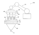
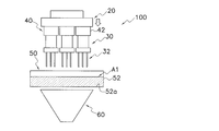
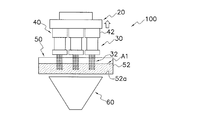
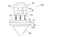
- FIG. 1 is a schematic view of the weighing device 100. Further, FIG. 2 is a block diagram of the weighing device 100. In FIGS. 1 and 2, the weighing device 100 is a device that takes out a part of the article A from the article group A1 which is a collection of the articles A and discharges the article A.
- the weighing device 100 takes out a part of the article A from the article group A1 so that the weight is within the target weight range and discharges the article A.
- the article A discharged by the measuring device 100 is, for example, packaged in a bag or contained in a container in a subsequent process of the measuring device 100, and shipped as a commercial product.
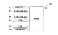
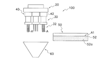
- the weighing device 100 includes a robot arm 10, a movable member 20, a gripper 30, a weighing unit 40, a mounting unit 50, a mounting unit driving unit 54, a discharge chute 60, and a control unit 70. ing.
- the control unit 70 performs various calculations and controls the operation of each unit of the weighing device 100.
- the article group A1 is placed in the placement section 50.
- Article A is, for example, food. Further, the article A is a highly sticky food such as noodles such as spaghetti and foods containing a large amount of sugars.
- the placement portion 50 has a first position in which the gripper 30 grips the article A of the article group A1 placed on the placement portion 50 by the placement portion drive unit 54, and the gripper 30 is placed on the placement portion 50. It is moved from the placed article group A1 to the second position where the article A is not gripped.
- Each gripper 30 has a gripping member 32 that grips the article A.
- a gripper 30 is attached to the movable member 20.
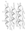
- a plurality of grippers 30 are attached to the movable member 20.
- the robot arm 10 moves the movable member 20 to which the gripper 30 is attached.
- the measuring unit 40 measures the weight value of the article A gripped by each of the gripping devices 30.
- the discharge chute 60 receives and discharges the article A released by the gripper 30.
- the control unit 70 controls the operation of various configurations of the weighing device 100 including the mounting unit driving unit 54, the gripping member driving mechanism 34, and the robot arm 10, and is a combination using the weight value of the article A weighed by the measuring unit 40. Perform calculations, etc.
- the control unit 70 controls the operation of the robot arm 10 to move the movable member 20, and brings the gripper 30 closer to the placement unit 50 placed at the first position where the article group A1 is placed.
- the control unit 70 controls the gripping member drive mechanism 34 of each gripping device 30, and transfers a part of the article A of the article group A1 placed on the mounting unit 50 to the gripping member 32 of each gripping device 30. To be grasped.
- Each measuring unit 40 weighs the weight value of the article A gripped by the gripper 30 corresponding to the measuring unit 40.
- the control unit 70 performs a combination calculation based on the weight value of the article A gripped by the gripping device 30 weighed by each measuring unit 40.
- the combination calculation is a process of finding a combination of weight values whose total value is within the target weight range as a result of adding the weight values of the articles A gripped by each of the grippers 30. Based on the result of the combination calculation, the control unit 70 causes the grip member 32 of the gripper 30 corresponding to the combination of the weight values in the target weight range to release the grip of the article A above the discharge chute 60, and the discharge chute 70. Article A in the target weight range from 60 is discharged.
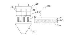
- FIG. 3 is a schematic perspective view of the robot arm 10, the movable member 20, the measuring unit 40, and the gripper 30.
- FIG. 4 is a schematic perspective view of the movable member 20, the measuring unit 40, and the gripper 30.
- FIG. 5A is a bottom view of the movable member 20 to which the gripper 30 is attached as viewed from the gripping member 32 side (lower side) of the gripper 30.
- 5B and 5C are bottom views of one of the gripping devices 30 of FIG. 5A, when the gripping member 32 of the gripping device 30 is viewed from below.
- the movable member 20 is a member to which the gripper 30 is attached. In the present embodiment, a plurality of grippers 30 are attached to the movable member 20.
- the movable member 20 is a frame that supports the gripper 30.
- the movable member 20 is a member that is moved by the robot arm 10.
- the aspect attached to the member 20 is also included.
- the gripper 30 is attached to the movable member 20 via the sensor unit 42 of the measuring unit 40.
- the robot arm 10 is a device that supports the movable member 20 and moves the movable member 20.
- the robot arm 10 moves the movable member 20 along a single axis.
- the robot arm 10 moves the movable member 20 up and down along a single axis extending in the vertical direction.
- the robot arm 10 is an articulated robot as shown in FIG.
- the type of robot arm 10 is not limited to the articulated robot.
- the robot arm 10 may be a device capable of moving the movable member 20 in a predetermined direction.
- the weighing device 100 may have a cylinder capable of moving the movable member 20 in a predetermined direction instead of the robot arm 10.
- the weighing device 100 may have a cylinder capable of moving the movable member 20 along a single axis instead of the robot arm 10.
- the gripper 30 is a device that grips the article A.
- Each gripping device 30 has a gripping member 32 and a gripping member driving mechanism 34 as a driving mechanism for driving the gripping member 32.
- the gripping member drive mechanism 34 drives the gripping member 32 using, for example, a motor or a fluid pressure as a drive source.
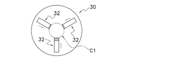
- the gripping member 32 is a rod-shaped or finger-shaped member as shown in FIG.
- Each gripping device 30 has a plurality of (for example, three) gripping members 32.
- the number and shape of the gripping members 32 drawn in FIG. 4 and the like are merely examples, and can be changed as appropriate.
- the plurality of gripping members 32 are arranged side by side in the circumferential direction. Further, when viewed from the gripping member 32 side of each gripping device 30, the plurality of gripping members 32 are arranged side by side at substantially equal intervals in the circumferential direction. Further, when each gripping device 30 is viewed from the gripping member 32 side, the gripping member 32 is movable in the radial direction.
- the gripping device 30 moves the gripping members 32, which are separated from each other, inward in the radial direction by the gripping member drive mechanism 34 to bring them closer to each other.
- the article A is sandwiched between the plurality of gripping members 32 to grip the article A.
- the gripping device 30 releases the gripping of the article A by moving the gripping members 32 in a state of being close to each other in the radial direction outward by the gripping member driving mechanism 34 so as to be separated from each other.
- a plurality of grippers 30 are attached to the movable member 20.
- Each gripper 30 is attached to the movable member 20 via the sensor unit 42 of the measuring unit 40.
- the sensor unit 42 of the measuring unit 40 is arranged between the gripper 30 and the movable member 20 that supports the gripper 30.
- 11 grippers 30 are attached to the movable member 20, but this is just an example and does not limit the number of grippers 30.
- the plurality of grippers 30 attached to the movable member 20 are integrally moved up and down by the robot arm 10 moving the movable member 20 up and down.
- each gripper 30 has a substantially circular shape when the gripper 30 attached to the movable member 20 is viewed from the grip member 32 side.
- the grippers 30 are arranged in a substantially staggered manner when the grippers 30 attached to the movable member 20 are viewed from the gripping member 32 side.
- the arrangement is an example and is not limited to the staggered arrangement.
- (2-4) Measuring unit 40 In the weighing device 100, one weighing unit 40 is provided for each gripping device 30. The measuring unit 40 measures the weight value of the article A gripped by the gripping member 32 of the corresponding gripping device 30.
- Each measuring unit 40 includes a sensor unit 42 and a control unit (not shown). As shown in FIG. 4, each gripper 30 is attached to the movable member 20 via the sensor unit 42.
- the sensor unit 42 includes a force sensor and an acceleration sensor.
- As the force sensor for example, a strain gauge type load cell is adopted.
- As the acceleration sensor for example, a strain gauge type load cell or a MEMS type small acceleration sensor is adopted.
- the control unit of the measuring unit 40 grips the gripper 30 based on the force and acceleration measured by the sensor unit 42 when the gripper 30 in the state of gripping the article A is moved along with the movement of the movable member 20.
- the mass of the article A is measured.
- the control unit of the measuring unit 40 measures the mass of the article A gripped by the gripper 30 by dividing the force measured by the force sensor by the acceleration measured by the acceleration sensor. ..
- the measuring unit 40 is not limited to the method of measuring the mass of the article A based on the force and the acceleration measured when the gripper 30 moves.
- the measuring unit 40 may use a load cell or the like to weigh the article A gripped by the stationary gripper 30.
- the article group A1 is placed in the placement section 50.
- the placement unit 50 includes an article group storage container 52 in which the article A (article group A1) is housed.
- the article group A1 is placed on the placement surface 52a (here, the bottom surface of the article group storage container 52).
- the gripper 30 grips a part of the article A from the article group A1 housed in the article group storage container 52.
- the article group storage container 52 is a rectangular parallelepiped container with an open upper part.
- the placement unit 50 causes a person or a machine to renew the article group accommodating container 52 (article) in which the amount of the article A inside the article group accommodating container 52 is reduced. It is configured to be replaceable with the article group storage container 52 (in which a large amount of A is stored).
- the placement unit 50 may have an article supply mechanism for supplying the article A to the article group accommodating container 52 instead of the article group accommodating container 52 being configured to be replaceable.
- the mounting unit 50 is moved between the first position and the second position by the mounting unit driving unit 54.
- the mounting unit driving unit 54 moves the mounting unit 50 by using, for example, a motor or a fluid pressure as a driving source.
- the first position is the position where the gripper 30 grips the article A of the article group A1 placed on the placement portion 50.
- the second position is a position where the gripper 30 does not grip the article A from the article group A1 placed on the placement portion 50.
- the mounting unit driving unit 54 moves the mounting unit 50 between the first position and the second position in a direction intersecting the moving direction of the movable member 20. In the present embodiment, the mounting unit driving unit 54 moves the mounting unit 50 in the horizontal direction between the first position and the second position.
- the first position of the placement portion 50 is a position directly below the gripper 30.
- the movable member 20 is moved by the robot arm 10, and when the gripper 30 is brought closer to a predetermined position with respect to the mounting portion 50, the gripper 30 is moved by the mounting portion 50.
- the article A placed on the robot can be gripped.
- the first position of the mounting portion 50 is a position directly above the discharge chute 60.
- the second position of the placement portion 50 is a position just below the gripper 30.
- the gripper 30 is mounted on the mounting portion 50 when the mounting portion 50 is in the second position. It is not possible to grasp the article A that is present.
- the second position of the placement portion 50 is a position just above the discharge chute 60.
- the discharge chute 60 is a funnel-shaped member.
- the discharge chute 60 is arranged directly below the gripper 30. Further, the discharge chute 60 is arranged directly below the placement portion 50 when the placement portion 50 is in the first position. In other words, the mounting portion 50 located at the first position is arranged between the gripper 30 and the discharge chute 60.
- the placement portion 50 when the placement portion 50 is in the second position, the placement portion 50 does not exist between the gripper 30 and the discharge chute 60.
- the discharge chute 60 discharges the article A supplied from the gripper 30 to the outside of the weighing device 100 when the gripper 30 releases the grip. Specifically, when the mounting portion 50 is located at the second position, the discharge chute 60 receives the article A that the gripper 30 releases the grip and drops, and discharges it to the outside of the weighing device 100.
- Control unit 70 includes a CPU (not shown) and a memory such as a ROM or RAM. As shown in FIG. 2, the control unit 70 is electrically connected to the robot arm 10, the gripping member driving mechanism 34, the measuring unit 40, and the mounting unit driving unit 54.
- the control unit 70 controls the operation of various configurations of the weighing device 100 such as the robot arm 10, the gripping member drive mechanism 34, and the mounting unit drive unit 54 by executing a program stored in the memory by the CPU. A combination calculation or the like using the weight value of the article A weighed by the measuring unit 40 is performed.
- control unit 70 may not be realized by software, may be realized by hardware, or may be realized by cooperation between hardware and software.
- control unit 70 sets a first control mode and a second control mode different from the first control mode as control modes of the grip member drive mechanism 34. Have.
- control unit 70 controls the gripping member drive mechanism 34 to cause the gripping member 32 to execute the first operation.
- the first operation is an operation in which the gripping member 32 grips the article A and then releases the grip of the article A.
- a plurality of gripping members 32 located at positions separated from each other as shown in FIG. 5B move inward in the radial direction, move to positions close to each other as shown in FIG. 5C, and then move. It is a series of operations of returning to positions separated from each other as shown in FIG. 5B again.
- control unit 70 controls the gripping member drive mechanism 34 to cause the gripping member 32 to execute the second operation.
- the second operation is an operation in which the gripping member 32 removes deposits adhering to the gripping member 32.
- the deposit is, for example, the article A itself, an adhesive substance contained in the article A, or the like.
- the deposits are noodles or ingredients, spaghetti sauce, and the like.
- control unit 70 have a second control mode as the control mode of the gripping member drive mechanism 34.
- the weighing unit 40 corresponding to the gripping device 30 measures not only the weight of the article A gripped by the gripping member 32 but also the weight of the deposits adhering to the gripping member 32 as the weight of the article A.
- the deposit since the deposit is not the article A gripped by the grip member 32, the deposit may not fall from the grip member 32 even if the grip member 32 releases the grip of the article A.
- control unit 70 has a second control mode as a control mode of the gripping member drive mechanism 34, and the gripping member 32 performs a second operation of removing deposits adhering to the gripping member 32. Such problems can be reduced.
- the second operation of the gripping member 32 is an operation different from the first operation.
- the difference between the first operation and the second operation includes a case where the mode of movement of the grip member 32 in the first operation is different from the mode of movement of the grip member 32 in the second operation.
- the difference between the first operation and the second operation is that the mode of movement of the grip member 32 is the same, and either the operation speed of the grip member 32 or the number of times the operation is executed in the first operation and the second operation. Including the case where is different.
- the average operating speed at which the gripping member 32 moves from the remote position to the near position (hereinafter referred to as the approaching speed) is faster than the approaching speed during the first operation.
- the average operating speed at which the gripping member 32 moves from the close position to the remote position (hereinafter referred to as the separation speed) is the separation during the first operation. Faster than hourly speed.
- the grip member 32 is moved from the remote position to the close position and / or the grip member 32 is moved from the close position to the remote position in a shorter time than during the first operation. ..
- the approach speed and the separation speed during the second operation are faster than the approach speed and the separation speed during the first operation, respectively.
- the approaching speed and the separating speed of the gripping member 32 during the second operation are twice or more (more preferably five times or more) faster than the approaching speed and the separating speed during the first operation. Is.
- the maximum acceleration of the gripping member 32 when moving the gripping member 32 from the remote position to the close position during the second operation (hereinafter referred to as the approaching acceleration) is larger than the approaching acceleration during the first operation. ..
- the maximum deceleration of the gripping member 32 (negative acceleration during deceleration) when moving the gripping member 32 from a remote position to a close position during the second operation.
- the absolute value of, hereinafter referred to as deceleration when approaching) is larger than the deceleration when approaching during the first operation.
- the maximum acceleration of the gripping member 32 when the gripping member 32 is moved from the close position to the remote position during the second operation (hereinafter referred to as the acceleration at the time of separation) is determined. It is larger than the acceleration at the time of separation during the first operation.
- the maximum deceleration of the gripping member 32 (negative acceleration during deceleration) when moving the gripping member 32 from a close position to a remote position during the second operation.
- the absolute value of, hereinafter referred to as deceleration at the time of approaching) is larger than the acceleration at the time of separation during the first operation.
- the approaching acceleration and the separating acceleration of the gripping member 32 during the second operation are twice or more (more preferably five times or more) as compared with the approaching acceleration and the separating acceleration during the first operation. ..
- the deceleration at the time of approaching and the deceleration at the time of separation during the second operation of the gripping member 32 are twice or more (more preferably 5 times) as compared with the deceleration at the time of approaching and the deceleration at the time of separation during the first operation.
- the deceleration at the time of approaching and the deceleration at the time of separation during the second operation of the gripping member 32 are twice or more (more preferably 5 times) as compared with the deceleration at the time of approaching and the deceleration at the time of separation during the first operation.
- the deceleration at the time of approaching and the deceleration at the time of separation during the first operation are twice or more (more preferably 5 times) as compared with the deceleration at the time of approaching and the de
- (B) Second Example of Second Movement of Gripping Member 32 The second movement of the gripping member 32 of the first example is arranged at a remote position apart from each other as shown in FIG. 5B, similarly to the first movement. This is a series of operations in which the plurality of gripping members 32 move inward in the radial direction to move to a close position as shown in FIG. 5C, and then return to a remote position again.
- the number of times the gripping member 32 is operated from the remote position to the close position or from the close position to the remote position is larger than that during the first operation. For example, at the time of the first operation, a series of operations in which the gripping member 32 moves from the remote position to the close position and returns to the remote position are executed once. On the other hand, at the time of the second operation, a series of operations in which the gripping member moves from the remote position to the close position and returns to the remote position are executed a plurality of times. For example, during the second operation, the gripping member 32 executes a series of operations two or more times (more preferably four times or more).
- the gripping member 32 does not have to move in the range between the remote position and the close position as in the first movement.
- the gripping member 32 may move in a narrower range during the second operation than during the first operation.
- the amount of movement of the gripping member 32 during the second operation is set to 3/4 or less (more preferably 1/2 or less) of the amount of movement of the gripping member 32 during the first operation.
- the moving amount of the gripping member 32 during the second operation is set to 1/8 or more of the moving amount of the gripping member 32 during the first operation.
- the control unit 70 combines the modes of the first to third examples so that the grip member 32 reciprocates a narrow section a plurality of times at high speed to reciprocate the grip member drive mechanism 34. Control. By such control of the control unit 70, the gripping member 32 vibrates at high speed. When the gripping member 32 performs such an operation, the removal of the deposits adhering to the gripping member 32 is easily promoted.
- the aspects of the first to third examples of the above second operation do not need to be combined at the same time, but may be combined as appropriate.
- the control unit 70 makes the same movement as the first movement (movement from the remote position to the close position and back to the remote position) once. Only, the gripping member drive mechanism 34 may be controlled so as to perform at high speed.
- 6A to 6I are schematic side views of the weighing device 100 for explaining the operation of the weighing device 100 of FIG.
- FIGS. 6A to 6I the drawing of the robot arm 10 for moving the movable member 20 is omitted.
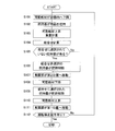
- FIG. 7A is a flowchart for explaining the operation of the weighing device 100 according to the first embodiment.
- FIG. 6A depicts the initial state before the gripper 30 grips the article A.
- the movable member 20 is arranged at a predetermined position so that the gripping member 32 of the gripping device 30 is arranged outside the article group storage container 52 of the mounting portion 50.
- the placement portion 50 is arranged at a first position directly below the gripper 30.
- the gripping member 32 of each gripping device 30 is arranged at a remote position as shown in FIG. 5B.
- Step S1 During the operation of the weighing device 100, the control unit 70 controls the robot arm 10 to move the movable member 20 vertically downward from the initial state, and brings the plurality of grippers 30 closer to the mounting unit 50.
- control unit 70 controls the operation of the robot arm 10 and is movable so that the gripping member 32 of the gripper 30 is arranged at a predetermined position where the article A in the article group storage container 52 can be gripped.
- the member 20 is moved vertically downward (see FIG. 6B).
- control unit 70 controls the operation of the robot arm 10 so that at least a part of the gripping member 32 is inserted into the article group A1 and moves the movable member 20 vertically downward. ..
- Step S2 the control unit 70 controls the gripping member driving mechanism 34 of each gripping device 30 to cause the gripping member 32 to grip the article A.
- the control unit 70 causes a plurality of grippers 30 to grip the article A at the same time.
- the present invention is not limited to this, and the control unit 70 may have a plurality of grippers 30 grip the article A at different timings.
- Step S3 the control unit 70 controls the robot arm 10 in a state where the plurality of grippers 30 grip the article A, and the grip member 32 of the gripper 30 is outside the article group storage container 52 of the placement portion 50.
- the movable member 20 is moved vertically upward so as to be arranged in (see FIG. 6C).
- each measuring unit 40 weighs the article A gripped by the corresponding gripper 30.
- Step S4 the control unit 70 determines that at least one of the operating state of each gripper 30 and the weighing result of the measuring unit 40 does not discharge the article A gripped by the gripper 30 to the discharge chute 60, but rather to the article group storage container 52. It is determined whether or not the predetermined conditions for returning are satisfied.
- the main purpose of this determination is to move the article group storage container 52 when it is estimated that the weight value of the article A weighed by the measuring unit 40 is not a preset target weight value or is not a target weight value. By returning the article group to the article group storage container 52 in advance, it is intended to prevent the article A from being accidentally discharged to the discharge chute 60.
- "corresponding to the prescribed conditions” means (1) The weight value of the article A weighed by the measuring unit 40 is not a preset target weight value. (2) The amount of movement of the gripping member 32 to hold the article A is larger than the predetermined range. (3) The amount of movement of the gripping member 32 to hold the article A is smaller than the predetermined range. It corresponds to at least one of.
- the fact that the amount of movement of the gripping member 32 holding the article A is larger than the predetermined range means that the weight value of the article A is larger than the target weight value.
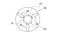
- FIG. 5D is a plan view of three gripping members 32 sandwiching a virtual article that matches the lower limit of the target weight value when viewed from the tip end side of the gripping member 32.
- the circle C1 is the smallest inscribed circle for the three gripping members 32.
- FIG. 5E is a plan view of three gripping members 32 sandwiching a virtual article that matches the upper limit of the target weight value when viewed from the tip end side of the gripping member 32.
- the circle C2 is the smallest inscribed circle for the three gripping members 32.
- the range surrounded by the circles C1 and C2 is a predetermined range R that satisfies the target weight value.
- FIG. 5F is a plan view of three gripping members 32 sandwiching a virtual article exceeding the upper limit of the target weight value when viewed from the tip end side of the gripping member 32.
- the circle Ca is located outside the predetermined range R when viewed from the center of the circle. That is, it means that the arrival position (coordinates) of each grip member 32 is outside the arrival position (coordinates) of the grip member sandwiching the virtual article that matches the upper limit of the target weight value.
- the movement amount of the operation of holding the article A by the gripping member 32 is smaller than the predetermined range, which means that the weight value of the article is smaller than the target weight value.
- FIG. 5G is a plan view of three gripping members 32 sandwiching a virtual article having a weight value less than the lower limit of the target weight value when viewed from the tip end side of the gripping member 32.
- the circle Cb is located inside the predetermined range R when viewed from the center of the circle. That is, it means that the arrival position (coordinates) of each grip member 32 is inside the arrival position (coordinates) of the grip member 32 sandwiching the virtual article that matches the lower limit of the target weight value.
- step S2 determines whether or not any of the above predetermined conditions (2) and (3) is satisfied.
- step S3 May be provided with a step for determining whether or not the above-mentioned predetermined conditions (2) and (3) are satisfied. Details will be described in [(5) Modified example of the first embodiment] in the latter part.
- step S5 When the control unit 70 determines that the operating state of each gripper 30 and at least one of the weighing results of the measuring unit 40 meet the predetermined conditions, the process proceeds to step S5, and when it is determined that the measurement results do not correspond to the predetermined conditions, the control unit 70 proceeds to step S5. Proceed to step S6.
- Step S5 the control unit 70 controls the gripping member drive mechanism 34 of the gripper 30 that corresponds to at least one of the predetermined conditions (1), (2), and (3), and causes the gripper 30 to have the article A. Is released (see FIG. 6D).
- control unit 70 controls the gripping member drive mechanism 34 of the gripper 30 to cause the gripper 30. The grip of the article A is released.
- the article A gripped by the gripper 30 falls into the article group storage container 52 of the placement portion 50 arranged at the first position, and is reused as the article A of the article group A1. At this point, the gripping member 32 of the gripper 30 that meets the above-mentioned predetermined conditions completes the first operation.
- control unit 70 controls the gripping member driving mechanism 34 of the gripping device 30 immediately after the gripping member 32 of the gripping device 30 releases the gripping of the article A by the first operation, and the gripping member 32 is second. Perform the operation.
- the article A is an article that is difficult to adhere to the gripping member 32, it is not always necessary to execute the second operation.
- the article A of the gripper 30 By returning the article A of the gripper 30 corresponding to at least one of the conditions (1), (2) and (3) to the article group storage container 52, the article A having the "article A whose weight value is not the target weight value" is obtained. It is avoided to operate as it is. As a result, it is possible to prevent the article from falling from the gripper 30 and lowering the weighing accuracy. Further, unnecessary operation is eliminated, and production efficiency can be improved.
- Step S6 the control unit 70 controls the mounting unit driving unit 54 to move the mounting unit 50 from the first position to the second position (see FIG. 6E).
- the placement portion 50 moves to the second position, the placement portion 50 is not arranged between the gripper 30 and the discharge chute 60.
- Step S7 the control unit 70 controls the robot arm 10 to move the movable member 20 vertically downward to bring the plurality of grippers 30 closer to the discharge chute 60 (see FIG. 6F).
- the article may be dropped without moving the movable member 20 vertically downward.
- Step S8 the control unit 70 causes the gripper 30 that does not meet any of the predetermined conditions (1), (2), and (3) to release the grip of the article A in step 5, and causes the article A from the discharge chute 60. (See Fig. 6G).
- the gripping member 32 of the gripper 30 completes the first operation at this point.
- control unit 70 controls the gripping member driving mechanism 34 of the gripping device 30 immediately after the gripping member 32 of the gripping device 30 releases the gripping of the article A by the first operation, and the gripping member 32 is second. Perform the operation.
- the article A is an article that is difficult to adhere to the gripping member 32, it is not always necessary to execute the second operation.
- Step S9 When the discharge of the article A is completed, the control unit 70 controls the robot arm 10 to return the movable member 20 to the original position (see FIG. 6H).
- Step S10 the control unit 70 controls the mounting unit driving unit 54 to return the mounting unit 50 from the second position to the first position directly below the gripper 30 (see FIG. 6I).
- Step S11 the control unit 70 determines whether or not there is an operation stop command.
- the control unit 70 stops the control when it is determined that the operation stop command is present, and returns to step S1 when it is determined that there is no operation stop command.
- the operation of the weighing device 100 described here is only an example, and can be appropriately changed within a consistent range.
- control unit 70 controls the robot arm 10 in a state where the plurality of grippers 30 grip the article A, and the movable member 20 is drawn in FIG. 6C from the position drawn in FIG. 6B.
- the robot arm 10 may be controlled so as to move the movable member 20 downward one or more times when the movable member 20 is moved upward to the desired position.
- the article attached to the grip member 32 can be eliminated by the vertical movement of the movable member 20 as described above.
- the article attached to the gripping member 32 is an article that is not gripped by the gripping member 32 and may fall regardless of the operation of the gripping member 32.
- the weight of the article A to be weighed by the measuring unit 40 is measured by the weight of the article A held by the gripping member 32. It is possible to improve the weighing accuracy by approaching.
- the control unit 70 determines that at least one of the operating state of the gripper 30 and the weighing result of the measuring unit 40 is (1) a target weight value in which the weight value of the article A weighed by the measuring unit 40 is preset. (2) The amount of movement of the gripping member 32 holding the article A is larger than the predetermined range, and (3) the amount of movement of the gripping member 32 holding the article A is smaller than the predetermined range. When any of the above conditions is met, the article A gripped by the gripper 30 is returned to the article group storage container 52 without being discharged to the discharge chute 60.
- the fact that the movement amount of the operation of holding the article A by the gripper 30 is larger than the predetermined range means that the weight value of the article is larger than the target weight value.
- the minimum inscribed circle for each gripping member 32 when the article matching the lower limit of the target weight value is sandwiched and the upper limit of the target weight value match.
- the range surrounded by the minimum inscribed circle for each gripping member 32 when the article A is sandwiched is a predetermined range R that satisfies the target weight value.
- the minimum inscribed circle for each gripping member 32 when the article A exceeding the upper limit of the target weight value is sandwiched is located outside the predetermined range R when viewed from the center of the circle. That is, it means that the arrival position (coordinates) of each grip member is outside the arrival position (coordinates) of the grip member 32 sandwiching the article A that matches the upper limit of the target weight value.
- the fact that the movement amount of the operation of holding the article A by the gripper 30 is smaller than the predetermined range means that the weight value of the article is smaller than the target weight value.
- the minimum inscribed circle for each gripping member 32 when the article A less than the lower limit of the target weight value is sandwiched is located inside the predetermined range R when viewed from the center of the circle. That is, it means that the arrival position (coordinates) of each grip member 32 is inside the arrival position (coordinates) of the grip member 32 sandwiching the article A that matches the lower limit of the target weight value.
- the gripper 30 operates while holding the "article whose weight value is not the target weight value". As a result, it is possible to prevent the article A from falling from the gripper 30 and lowering the weighing accuracy. In addition, unnecessary operation is eliminated, and production efficiency can be improved.
- the amount of movement of the gripping device 30 for holding the article A is the opening degree of the gripping member 32.
- the fact that the opening degree of the gripping member 32 is larger than the predetermined range means that the weight value of the article A is larger than the target weight value. Further, the fact that the opening degree of the gripping member 32 is smaller than the predetermined range means that the weight value of the article A is smaller than the target weight value.
- FIG. 7B is a flowchart for explaining the operation of the weighing device 100 according to the modified example of the first embodiment.
- the difference between this modification and FIG. 7A is that steps S2a and S2b are inserted between steps S2 and S3.
- steps S1, S2, and S3 to S11 in FIG. 7B are the same as those in FIG. 7A, the description thereof will be omitted, and here, the newly inserted steps S2a and S2b will be described.
- Step S2a the control unit 70 corresponds to a predetermined condition for the operating state of each gripper 30 to return the article A gripped by the gripper 30 to the article group storage container 52 without discharging it to the discharge chute 60. Determine if it is.
- corresponding to a predetermined condition means that (2) the article A by the gripping member 32 excluding (1) from the predetermined conditions (1) to (3) described in step S4 of the first embodiment.
- the amount of movement to have is larger than the specified range, (3)
- the amount of movement of the gripping member 32 to hold the article A is smaller than the predetermined range. It corresponds to at least one of.
- step S2 when the control unit 70 causes the gripping member 32 to grip the article A, it is possible to determine whether the amount of movement of the gripping member 32 holding the article A is larger or smaller than the predetermined range. Therefore, it is not necessary to wait until the control unit 70 moves the movable member 20 vertically upward as in the first embodiment.
- control unit 70 determines that the operating state of each gripper 30 meets the above-mentioned predetermined conditions (2) or (3), the control unit 70 proceeds to step S2b, and when it determines that the operating state does not correspond to the predetermined conditions (2) or (3), the control unit 70 proceeds to step S3. Proceed to.
- Step S2b the control unit 70 controls the gripping member drive mechanism 34 of the gripping device 30 that corresponds to at least one of the predetermined conditions (2) and (3), and releases the gripping device 30 from gripping the article A. (See FIG. 6D).
- control unit 70 controls the gripping member drive mechanism 34 of the gripper 30 to cause the gripper 30. The grip of the article A is released.
- the article A gripped by the gripper 30 falls into the article group storage container 52 of the placement portion 50 arranged at the first position, and is reused as the article A of the article group A1. At this point, the gripping member 32 of the gripper 30 that meets the above-mentioned predetermined conditions completes the first operation.
- control unit 70 controls the gripping member driving mechanism 34 of the gripping device 30 immediately after the gripping member 32 of the gripping device 30 releases the gripping of the article A by the first operation, and the gripping member 32 is second. Perform the operation.
- the article A is an article that is difficult to adhere to the gripping member 32, it is not always necessary to execute the second operation.
- the product By returning the article A of the gripper 30 corresponding to at least one of the conditions (2) and (3) to the article group storage container 52, the product operates while holding the "article A whose weight value is not the target weight value". Is avoided. As a result, it is possible to prevent the article from falling from the gripper 30 and lowering the weighing accuracy. Further, unnecessary operation is eliminated, and production efficiency can be improved.
- the structure of the measuring device according to the second embodiment uses the structure of the measuring device according to the first embodiment as it is, and only the control is different. Therefore, detailed description of each part is omitted.
- FIG. 8A is a flowchart for explaining the operation of the weighing device 100 according to the second embodiment.
- the movable member 20 is arranged at a predetermined position so that the gripping member 32 of the gripping device 30 is arranged outside the article group storage container 52 of the mounting portion 50.
- the placement portion 50 is arranged at a first position directly below the gripper 30.
- the gripping member 32 of each gripping device 30 is arranged at a remote position as shown in FIG. 5B.
- Step S101 During the operation of the weighing device 100, the control unit 70 controls the robot arm 10 to move the movable member 20 vertically downward from the initial state, and brings the plurality of grippers 30 closer to the mounting unit 50.
- control unit 70 controls the operation of the robot arm 10 and is movable so that the gripping member 32 of the gripper 30 is arranged at a predetermined position where the article A in the article group storage container 52 can be gripped.
- the member 20 is moved vertically downward (see FIG. 6B).
- control unit 70 controls the operation of the robot arm 10 so that at least a part of the gripping member 32 is inserted into the article group A1 and moves the movable member 20 vertically downward. ..
- Step S102 the control unit 70 controls the gripping member drive mechanism 34 of each gripping device 30 to cause the gripping member 32 to grip the article A.
- the control unit 70 causes a plurality of grippers 30 to grip the article A at the same time.
- the present invention is not limited to this, and the control unit 70 may have a plurality of grippers 30 grip the article A at different timings.
- step S102 Since it is possible to determine whether or not any of the predetermined conditions (2) and (3) in the first embodiment is met when step S102 is completed, the above is performed between step S102 and step S103. A step may be provided to determine whether or not the predetermined conditions (2) and (3) are satisfied. Details will be described in [(3) Modified example of the second embodiment] in the latter part.
- Step S103 the control unit 70 controls the robot arm 10 in a state where the plurality of grippers 30 grip the article A, and the grip member 32 of the gripper 30 is outside the article group storage container 52 of the placement portion 50.
- the movable member 20 is moved vertically upward so as to be arranged in (see FIG. 6C).
- each measuring unit 40 weighs the article A gripped by the corresponding gripper 30.
- Step S104 the control unit 70 performs a combination calculation using the weight value of the article A gripped by each gripper 30 weighed from each measuring unit 40, and finds a combination of weight values whose total value is in the target weight range. ..
- Step S105 the control unit 70 determines whether or not there is a gripper 30 that is not selected as a combination among the grippers 30.
- the control unit 70 proceeds to step S6 when it is determined that there is a gripper 30 which is not selected for the combination, and proceeds to step S7 when it is determined that the gripper 30 which is not selected for the combination.
- Step S106 Next, if there is a gripper 30 in which the weight of the article A to be gripped is not selected for the combination, the control unit 70 controls the gripping member drive mechanism 34 of the gripper 30, and by the first operation, the gripper 30 is controlled. The gripper 30 is made to release the grip of the article A (see FIG. 6D).
- the article A gripped by the gripper 30 falls into the article group storage container 52 of the placement portion 50 arranged at the first position, and is reused as the article A of the article group A1. At this point, the gripping member 32 of the gripper 30 that is not selected for the combination completes the first operation.
- control unit 70 controls the gripping member driving mechanism 34 of the gripping device 30 immediately after the gripping member 32 of the gripping device 30 that has released the gripping of the article A releases the gripping of the article A by the first operation. , Let the gripping member 32 perform the second operation. When the article A is an article that is difficult to adhere to the gripping member 32, it is not always necessary to execute the second operation.
- Step S107 the control unit 70 controls the mounting unit driving unit 54 to move the mounting unit 50 from the first position to the second position (see FIG. 6E).
- the placement portion 50 moves to the second position, the placement portion 50 is not arranged between the gripper 30 and the discharge chute 60.
- Step S108 the control unit 70 controls the robot arm 10 to move the movable member 20 vertically downward to bring the plurality of grippers 30 closer to the discharge chute 60 (see FIG. 6F).
- Step S109 the control unit 70 causes the gripper 30 corresponding to the combination of the weight values in the target weight range above the discharge chute 60 to release the grip of the article A based on the result of the combination calculation, and from the discharge chute 60. Discharge article A (see FIG. 6G).
- the gripping member 32 of the gripping device 30 selected for the combination completes the first operation at this point.
- control unit 70 controls the gripping member driving mechanism 34 of the gripping device 30 immediately after the gripping member 32 of the gripping device 30 that has released the gripping of the article A releases the gripping of the article A by the first operation. , Let the gripping member 32 perform the second operation. When the article A is an article that is difficult to adhere to the gripping member 32, it is not always necessary to execute the second operation.
- Step S110 When the discharge of the article A is completed for all the combinations of the weight values within the target weight range, the control unit 70 controls the robot arm 10 to return the movable member 20 to the original position (see FIG. 6H). ..
- Step S111 the control unit 70 controls the mounting unit driving unit 54 to return the mounting unit 50 from the second position to the first position directly below the gripper 30 (see FIG. 6I).
- Step S112 the control unit 70 determines whether or not there is an operation stop command.
- the control unit 70 stops the control when it is determined that the operation stop command is present, and returns to step S1 when it is determined that there is no operation stop command.
- the operation of the weighing device 100 described here is only an example, and can be appropriately changed within a consistent range.
- control unit 70 controls the robot arm 10 in a state where the plurality of grippers 30 grip the article A, and the movable member 20 is drawn in FIG. 6C from the position drawn in FIG. 6B.
- the robot arm 10 may be controlled so as to move the movable member 20 downward one or more times when the movable member 20 is moved upward to the desired position.
- the article attached to the grip member 32 can be eliminated by the vertical movement of the movable member 20 as described above.
- the article attached to the gripping member 32 is an article that is not gripped by the gripping member 32 and may fall regardless of the operation of the gripping member 32.
- the weight of the article A to be weighed by the measuring unit 40 is measured by the weight of the article A held by the gripping member 32. It is possible to improve the weighing accuracy by approaching.
- control unit 70 discharges the articles gripped by all the gripping units to the article group storage container 52 when there is no combination that becomes the target weight value.
- FIG. 8B is a flowchart for explaining the operation of the weighing device 100 according to the modified example of the second embodiment.
- the difference between this modification and FIG. 8A is that step S102a and step S102b are inserted between step S102 and step S103.
- steps S101, S102, and S103 to S112 in FIG. 8B are the same as those in FIG. 8A, the description thereof will be omitted, and here, the newly inserted steps S102a and S102b will be described.
- Step S102a the control unit 70 determines whether or not there is a gripper 30 that is not selected as a combination among the grippers 30.
- not selected as a combination among the gripping devices 30 means (2) gripping excluding (1) among the predetermined conditions (1) to (3) described in step S4 of the first embodiment.
- the amount of movement of the member 32 to hold the article A is larger than the predetermined range.
- (3) The amount of movement of the gripping member 32 to hold the article A is smaller than the predetermined range. It corresponds to at least one of.
- step S102 when the control unit 70 causes the gripping member 32 to grip the article A, it is possible to determine whether the amount of movement of the gripping member 32 holding the article A is larger or smaller than the predetermined range. Therefore, unlike the first embodiment and the second embodiment, it is not necessary to wait until the control unit 70 moves the movable member 20 vertically upward.
- control unit 70 determines that the operating state of each gripper 30 meets the above-mentioned predetermined conditions (2) or (3), the control unit 70 proceeds to step S102b, and when it determines that the operating state does not correspond to the predetermined conditions (2) or (3), the control unit 70 proceeds to step S3. Proceed to.
- Step S102b the control unit 70 controls the gripping member drive mechanism 34 of the gripping device 30 that corresponds to at least one of the predetermined conditions (2) and (3), and releases the gripping device 30 from gripping the article A. (See FIG. 6D).
- control unit 70 controls the gripping member drive mechanism 34 of the gripper 30, and by the first operation, the gripper 30 is controlled.
- the gripper 30 is made to release the grip of the article A.
- the article A gripped by the gripper 30 falls into the article group storage container 52 of the placement portion 50 arranged at the first position, and is reused as the article A of the article group A1. At this point, the gripping member 32 of the gripper 30 that meets the above-mentioned predetermined conditions completes the first operation.
- control unit 70 controls the gripping member driving mechanism 34 of the gripping device 30 immediately after the gripping member 32 of the gripping device 30 releases the gripping of the article A by the first operation, and the gripping member 32 is second. Perform the operation.
- the article A is an article that is difficult to adhere to the gripping member 32, it is not always necessary to execute the second operation.
- control unit 70 moves the gripper 30 and the article group storage container 52 relative to each other when the article A gripped by the gripper 30 is returned to the article group storage container 52.
- the article group storage container 52 can move in the horizontal first direction and the second direction orthogonal to each other.
- the control unit 70 relatively moves the gripper 30 and the article group storage container 52 in either the first direction or the second direction. ..
- the article A is returned to the article group storage container 52 after grasping the positional relationship between the gripper 30 and the article group storage container 52 in planar coordinates, the article is returned so as to even out the distribution of the articles in the container. Is possible.
- At least one of the gripper 30 and the article group storage container 52 is rotatable about a vertical axis.
- the control unit 70 rotates the gripper 30 and the article group storage container 52 by a predetermined relative angle in a plan view. As a result, the place where the article A is returned can be shifted, and the possibility of grasping an appropriate amount of the article A can be increased.
- the minimum inscribed circle for each grip member 32 when the article A is sandwiched is within a predetermined range for determining whether the amount of movement of the grip member 32 for holding the article A is larger or smaller than the predetermined range. It was determined by whether it was outside or inside R, that is, by the arrival position (coordinates) of the gripping member 32.
- the operating amount of the gripping member 32 is larger than that when gripping the article having the target weight value. Will also grow.
- the amount of movement of the gripping member 32 is smaller than when gripping the article having the target weight value.
- the operation of holding the article by the gripping portion when the gripping member 32 is in the fully open state at the start of the gripping operation, when the amount of movement is considered in terms of "displacement" with reference to the fully open state of the gripping member 32, "the operation of holding the article by the gripping portion".
- the amount of movement of the article is larger than the predetermined range "means that the weight value of the article is smaller than the target weight value. Further, “the amount of movement of the operation of holding the article by the grip portion is smaller than the predetermined range” means that the weight value of the article is larger than the target weight value.
- Robot arm 30 Grip device (grip part) 32 Gripping member (claw) 40 Measuring unit 52 Goods group storage container (container) 60 Discharge chute 70 Control unit 100 Weighing device A Article
Landscapes
- Engineering & Computer Science (AREA)
- Robotics (AREA)
- Mechanical Engineering (AREA)
- Physics & Mathematics (AREA)
- General Physics & Mathematics (AREA)
- Human Computer Interaction (AREA)
- Manipulator (AREA)
Priority Applications (3)
| Application Number | Priority Date | Filing Date | Title |
|---|---|---|---|
| CN202080067350.3A CN114467012B (zh) | 2019-09-26 | 2020-07-31 | 计量装置 |
| US17/761,947 US12264959B2 (en) | 2019-09-26 | 2020-07-31 | Weighing device |
| EP20867361.6A EP4036537B1 (en) | 2019-09-26 | 2020-07-31 | Measuring apparatus |
Applications Claiming Priority (2)
| Application Number | Priority Date | Filing Date | Title |
|---|---|---|---|
| JP2019-175388 | 2019-09-26 | ||
| JP2019175388A JP7491543B2 (ja) | 2019-09-26 | 2019-09-26 | 計量装置 |
Publications (1)
| Publication Number | Publication Date |
|---|---|
| WO2021059744A1 true WO2021059744A1 (ja) | 2021-04-01 |
Family
ID=75157683
Family Applications (1)
| Application Number | Title | Priority Date | Filing Date |
|---|---|---|---|
| PCT/JP2020/029431 Ceased WO2021059744A1 (ja) | 2019-09-26 | 2020-07-31 | 計量装置 |
Country Status (5)
| Country | Link |
|---|---|
| US (1) | US12264959B2 (https=) |
| EP (1) | EP4036537B1 (https=) |
| JP (2) | JP7491543B2 (https=) |
| CN (1) | CN114467012B (https=) |
| WO (1) | WO2021059744A1 (https=) |
Families Citing this family (7)
| Publication number | Priority date | Publication date | Assignee | Title |
|---|---|---|---|---|
| JP7491543B2 (ja) * | 2019-09-26 | 2024-05-28 | 株式会社イシダ | 計量装置 |
| JP7786724B2 (ja) * | 2022-03-15 | 2025-12-16 | 株式会社イシダ | 物品計量移動システム |
| JP7341550B1 (ja) * | 2022-03-25 | 2023-09-11 | コネクテッドロボティクス株式会社 | 把持システム |
| JP7364283B1 (ja) | 2022-09-29 | 2023-10-18 | コネクテッドロボティクス株式会社 | 把持システム、及び制御装置 |
| CN115781684B (zh) * | 2022-12-23 | 2024-09-03 | 梅卡曼德(北京)机器人科技有限公司 | 多抓阵列与物品之间的对齐方法、装置及物品抓取方法 |
| JP7780226B1 (ja) * | 2025-03-05 | 2025-12-04 | コネクテッドロボティクス株式会社 | 制御システム、及び制御プログラム |
| JP7833226B1 (ja) * | 2025-06-06 | 2026-03-19 | コネクテッドロボティクス株式会社 | 保持システム、及びプログラム |
Citations (5)
| Publication number | Priority date | Publication date | Assignee | Title |
|---|---|---|---|---|
| US5004093A (en) * | 1989-11-08 | 1991-04-02 | Charles Packaging Corporation | Straight line sorting and/or fill-to-weigh machine |
| JPH03202720A (ja) * | 1989-12-28 | 1991-09-04 | Yokohama Rubber Co Ltd:The | 粉粒体計量装置 |
| JPH063182A (ja) | 1992-03-07 | 1994-01-11 | Frisco Findus Ag | 秤量して分配する装置及び方法 |
| JP2001310284A (ja) * | 2000-04-25 | 2001-11-06 | Toshiba Mach Co Ltd | 製品搬送装置および製品搬送方法 |
| JP2019126876A (ja) * | 2018-01-24 | 2019-08-01 | 株式会社イシダ | 物品移載装置 |
Family Cites Families (34)
| Publication number | Priority date | Publication date | Assignee | Title |
|---|---|---|---|---|
| JPS56108917A (en) * | 1980-02-01 | 1981-08-28 | Ishida Scales Mfg Co Ltd | Metering device |
| JPS5786014A (en) * | 1980-11-18 | 1982-05-28 | Ishida Scales Mfg Co Ltd | Measuring or counting method by combination |
| US4789292A (en) * | 1984-04-06 | 1988-12-06 | Holcomb Gregory W | End effector for robotic equipment |
| IT1179334B (it) * | 1984-05-09 | 1987-09-16 | Azionaria Costr Macc Aut Spa | Apparecchiatura per distinguere in gruppi oggetti addossati posti di taglio e sopraggiungenti secondo linee erogatrici e per immettere gli stessi gruppi in una linea ricevitrice |
| JPH0732284A (ja) * | 1993-07-15 | 1995-02-03 | Nakai:Kk | 食品搬送ロボット装置 |
| JPH08145773A (ja) * | 1994-11-21 | 1996-06-07 | Yamato Scale Co Ltd | 定量計重方法とその装置 |
| JPH11292276A (ja) * | 1998-04-15 | 1999-10-26 | Mitsubishi Heavy Ind Ltd | 被把持物自動切り分け装置 |
| CA2273729A1 (en) * | 1998-07-14 | 2000-01-14 | Bayer Corporation | Robotics for transporting containers and objects within an automated analytical instrument and service tool for servicing robotics |
| DE60016788T2 (de) | 1999-09-10 | 2005-12-08 | Scanvaegt International A/S | Sortiervorrichtung |
| US6371717B1 (en) * | 2000-05-11 | 2002-04-16 | Abb Automation Inc. | Device for mechanically gripping and loading cylindrical objects |
| JP2003200906A (ja) | 2001-10-23 | 2003-07-15 | Naberu:Kk | 物品の選別包装装置 |
| JP5100566B2 (ja) * | 2008-08-07 | 2012-12-19 | 株式会社イシダ | 組合せ計量装置 |
| FR2936601B1 (fr) | 2008-09-30 | 2011-02-11 | Arbor Sa | Procede de traitement d'objets en fonction de leurs poids individuels |
| JP5308240B2 (ja) | 2009-06-09 | 2013-10-09 | アンリツ産機システム株式会社 | 組合せ集合装置 |
| DE102010002317B4 (de) * | 2010-02-24 | 2018-06-14 | Apologistics Gmbh | System und Verfahren zur Vereinzelung und Kommissionierung von Artikeln |
| JP5834491B2 (ja) | 2011-05-24 | 2015-12-24 | セイコーエプソン株式会社 | ロボットハンド、およびロボット |
| JP5733665B2 (ja) | 2011-06-21 | 2015-06-10 | ホクト株式会社 | 組み合わせ計測装置 |
| JP5383760B2 (ja) * | 2011-09-09 | 2014-01-08 | ファナック株式会社 | ワーク質量測定機能を備えたロボット |
| GB201215051D0 (en) | 2012-08-23 | 2012-10-10 | Ishida Europ Ltd | Weighing apparatus |
| PT3194311T (pt) | 2014-09-17 | 2021-08-20 | Unitec Spa | Aparelho de transporte aperfeiçoado para o transporte e pesagem de produtos agrícolas |
| JP7027030B2 (ja) | 2015-07-07 | 2022-03-01 | トーヨーカネツ株式会社 | ピッキングハンド及びピッキング移載装置 |
| JP6845559B2 (ja) | 2016-11-30 | 2021-03-17 | 株式会社イシダ | 物品移載装置 |
| JP2018112429A (ja) | 2017-01-10 | 2018-07-19 | 株式会社イシダ | 組合せ計量装置 |
| JP6831723B2 (ja) | 2017-03-16 | 2021-02-17 | 川崎重工業株式会社 | ロボットとロボットの運転方法 |
| CA3178148A1 (en) | 2017-04-24 | 2018-11-01 | Berkshire Grey Operating Company, Inc. | Systems and methods for providing singulation of objects for processing using object movement redistribution |
| JP7002217B2 (ja) | 2017-05-15 | 2022-01-20 | 株式会社前川製作所 | 食品把持装置、食品移載装置及び食品把持方法 |
| JP6438525B1 (ja) | 2017-05-26 | 2018-12-12 | ファナック株式会社 | 物品の重さを測定する重さ測定システムおよび方法 |
| JP7044366B2 (ja) | 2017-07-25 | 2022-03-30 | 株式会社ケー・デー・イー | 分配装置、盛付システム及び学習データ生成装置 |
| KR102403355B1 (ko) * | 2017-07-25 | 2022-06-02 | 현대자동차주식회사 | 차량, 그와 통신하는 모바일 기기 및 차량의 제어 방법 |
| JP6921411B2 (ja) | 2017-11-07 | 2021-08-18 | 株式会社イシダ | 物品供給装置及び組合せ計量装置 |
| JP7137953B2 (ja) * | 2018-03-29 | 2022-09-15 | 株式会社日本総合研究所 | 決済装置、決済方法および決済プログラム |
| CN108724167A (zh) * | 2018-06-01 | 2018-11-02 | 芜湖博创新能源科技有限公司 | 一种具有自动夹取和放置功能的制造用机械手 |
| JP7491543B2 (ja) * | 2019-09-26 | 2024-05-28 | 株式会社イシダ | 計量装置 |
| CN115312061B (zh) * | 2022-08-09 | 2026-02-10 | Oppo广东移动通信有限公司 | 驾驶场景中的语音问答方法、装置及车载终端 |
-
2019
- 2019-09-26 JP JP2019175388A patent/JP7491543B2/ja active Active
-
2020
- 2020-07-31 WO PCT/JP2020/029431 patent/WO2021059744A1/ja not_active Ceased
- 2020-07-31 EP EP20867361.6A patent/EP4036537B1/en active Active
- 2020-07-31 CN CN202080067350.3A patent/CN114467012B/zh active Active
- 2020-07-31 US US17/761,947 patent/US12264959B2/en active Active
-
2024
- 2024-05-08 JP JP2024075620A patent/JP7710760B2/ja active Active
Patent Citations (5)
| Publication number | Priority date | Publication date | Assignee | Title |
|---|---|---|---|---|
| US5004093A (en) * | 1989-11-08 | 1991-04-02 | Charles Packaging Corporation | Straight line sorting and/or fill-to-weigh machine |
| JPH03202720A (ja) * | 1989-12-28 | 1991-09-04 | Yokohama Rubber Co Ltd:The | 粉粒体計量装置 |
| JPH063182A (ja) | 1992-03-07 | 1994-01-11 | Frisco Findus Ag | 秤量して分配する装置及び方法 |
| JP2001310284A (ja) * | 2000-04-25 | 2001-11-06 | Toshiba Mach Co Ltd | 製品搬送装置および製品搬送方法 |
| JP2019126876A (ja) * | 2018-01-24 | 2019-08-01 | 株式会社イシダ | 物品移載装置 |
Also Published As
| Publication number | Publication date |
|---|---|
| JP7491543B2 (ja) | 2024-05-28 |
| EP4036537A4 (en) | 2022-11-30 |
| JP2021051045A (ja) | 2021-04-01 |
| EP4036537A1 (en) | 2022-08-03 |
| JP7710760B2 (ja) | 2025-07-22 |
| CN114467012B (zh) | 2025-08-22 |
| CN114467012A (zh) | 2022-05-10 |
| US12264959B2 (en) | 2025-04-01 |
| JP2024097886A (ja) | 2024-07-19 |
| EP4036537C0 (en) | 2024-12-25 |
| US20220333974A1 (en) | 2022-10-20 |
| EP4036537B1 (en) | 2024-12-25 |
Similar Documents
| Publication | Publication Date | Title |
|---|---|---|
| WO2021059744A1 (ja) | 計量装置 | |
| US11331795B2 (en) | Article gripping device | |
| JP2021051045A5 (https=) | ||
| US11826790B2 (en) | Article discharge system | |
| JP7345826B2 (ja) | 物品移動システム | |
| US12103189B2 (en) | Article discharge system | |
| US20200055185A1 (en) | Robot and method of operating the same | |
| JP2026069669A (ja) | 計量システム | |
| KR20250003575A (ko) | 식품 나눔 장치 및 프로그램 | |
| JP7841737B2 (ja) | 物品移動システム | |
| CN119365309A (zh) | 食品分份装置及程序 | |
| JP7786724B2 (ja) | 物品計量移動システム |
Legal Events
| Date | Code | Title | Description |
|---|---|---|---|
| 121 | Ep: the epo has been informed by wipo that ep was designated in this application |
Ref document number: 20867361 Country of ref document: EP Kind code of ref document: A1 |
|
| NENP | Non-entry into the national phase |
Ref country code: DE |
|
| ENP | Entry into the national phase |
Ref document number: 2020867361 Country of ref document: EP Effective date: 20220426 |
|
| WWG | Wipo information: grant in national office |
Ref document number: 17761947 Country of ref document: US |
|
| WWG | Wipo information: grant in national office |
Ref document number: 202080067350.3 Country of ref document: CN |