WO2021049223A1 - バルブ装置、流体循環回路 - Google Patents
バルブ装置、流体循環回路 Download PDFInfo
- Publication number
- WO2021049223A1 WO2021049223A1 PCT/JP2020/030381 JP2020030381W WO2021049223A1 WO 2021049223 A1 WO2021049223 A1 WO 2021049223A1 JP 2020030381 W JP2020030381 W JP 2020030381W WO 2021049223 A1 WO2021049223 A1 WO 2021049223A1
- Authority
- WO
- WIPO (PCT)
- Prior art keywords
- rotor
- flow path
- shaft
- fluid
- valve device
- Prior art date
- Legal status (The legal status is an assumption and is not a legal conclusion. Google has not performed a legal analysis and makes no representation as to the accuracy of the status listed.)
- Ceased
Links
Images


Classifications
-
- F—MECHANICAL ENGINEERING; LIGHTING; HEATING; WEAPONS; BLASTING
- F16—ENGINEERING ELEMENTS AND UNITS; GENERAL MEASURES FOR PRODUCING AND MAINTAINING EFFECTIVE FUNCTIONING OF MACHINES OR INSTALLATIONS; THERMAL INSULATION IN GENERAL
- F16K—VALVES; TAPS; COCKS; ACTUATING-FLOATS; DEVICES FOR VENTING OR AERATING
- F16K3/00—Gate valves or sliding valves, i.e. cut-off apparatus with closing members having a sliding movement along the seat for opening and closing
- F16K3/02—Gate valves or sliding valves, i.e. cut-off apparatus with closing members having a sliding movement along the seat for opening and closing with flat sealing faces; Packings therefor
- F16K3/04—Gate valves or sliding valves, i.e. cut-off apparatus with closing members having a sliding movement along the seat for opening and closing with flat sealing faces; Packings therefor with pivoted closure members
- F16K3/10—Gate valves or sliding valves, i.e. cut-off apparatus with closing members having a sliding movement along the seat for opening and closing with flat sealing faces; Packings therefor with pivoted closure members with special arrangements for separating the sealing faces or for pressing them together
-
- F—MECHANICAL ENGINEERING; LIGHTING; HEATING; WEAPONS; BLASTING
- F16—ENGINEERING ELEMENTS AND UNITS; GENERAL MEASURES FOR PRODUCING AND MAINTAINING EFFECTIVE FUNCTIONING OF MACHINES OR INSTALLATIONS; THERMAL INSULATION IN GENERAL
- F16K—VALVES; TAPS; COCKS; ACTUATING-FLOATS; DEVICES FOR VENTING OR AERATING
- F16K3/00—Gate valves or sliding valves, i.e. cut-off apparatus with closing members having a sliding movement along the seat for opening and closing
- F16K3/02—Gate valves or sliding valves, i.e. cut-off apparatus with closing members having a sliding movement along the seat for opening and closing with flat sealing faces; Packings therefor
- F16K3/04—Gate valves or sliding valves, i.e. cut-off apparatus with closing members having a sliding movement along the seat for opening and closing with flat sealing faces; Packings therefor with pivoted closure members
-
- B—PERFORMING OPERATIONS; TRANSPORTING
- B60—VEHICLES IN GENERAL
- B60H—ARRANGEMENTS OF HEATING, COOLING, VENTILATING OR OTHER AIR-TREATING DEVICES SPECIALLY ADAPTED FOR PASSENGER OR GOODS SPACES OF VEHICLES
- B60H1/00—Heating, cooling or ventilating [HVAC] devices
- B60H1/00485—Valves for air-conditioning devices, e.g. thermostatic valves
-
- F—MECHANICAL ENGINEERING; LIGHTING; HEATING; WEAPONS; BLASTING
- F01—MACHINES OR ENGINES IN GENERAL; ENGINE PLANTS IN GENERAL; STEAM ENGINES
- F01P—COOLING OF MACHINES OR ENGINES IN GENERAL; COOLING OF INTERNAL-COMBUSTION ENGINES
- F01P7/00—Controlling of coolant flow
- F01P7/14—Controlling of coolant flow the coolant being liquid
- F01P7/16—Controlling of coolant flow the coolant being liquid by thermostatic control
-
- F—MECHANICAL ENGINEERING; LIGHTING; HEATING; WEAPONS; BLASTING
- F16—ENGINEERING ELEMENTS AND UNITS; GENERAL MEASURES FOR PRODUCING AND MAINTAINING EFFECTIVE FUNCTIONING OF MACHINES OR INSTALLATIONS; THERMAL INSULATION IN GENERAL
- F16K—VALVES; TAPS; COCKS; ACTUATING-FLOATS; DEVICES FOR VENTING OR AERATING
- F16K11/00—Multiple-way valves, e.g. mixing valves; Pipe fittings incorporating such valves
- F16K11/02—Multiple-way valves, e.g. mixing valves; Pipe fittings incorporating such valves with all movable sealing faces moving as one unit
- F16K11/06—Multiple-way valves, e.g. mixing valves; Pipe fittings incorporating such valves with all movable sealing faces moving as one unit comprising only sliding valves, i.e. sliding closure elements
- F16K11/072—Multiple-way valves, e.g. mixing valves; Pipe fittings incorporating such valves with all movable sealing faces moving as one unit comprising only sliding valves, i.e. sliding closure elements with pivoted closure members
- F16K11/074—Multiple-way valves, e.g. mixing valves; Pipe fittings incorporating such valves with all movable sealing faces moving as one unit comprising only sliding valves, i.e. sliding closure elements with pivoted closure members with flat sealing faces
-
- F—MECHANICAL ENGINEERING; LIGHTING; HEATING; WEAPONS; BLASTING
- F16—ENGINEERING ELEMENTS AND UNITS; GENERAL MEASURES FOR PRODUCING AND MAINTAINING EFFECTIVE FUNCTIONING OF MACHINES OR INSTALLATIONS; THERMAL INSULATION IN GENERAL
- F16K—VALVES; TAPS; COCKS; ACTUATING-FLOATS; DEVICES FOR VENTING OR AERATING
- F16K3/00—Gate valves or sliding valves, i.e. cut-off apparatus with closing members having a sliding movement along the seat for opening and closing
- F16K3/02—Gate valves or sliding valves, i.e. cut-off apparatus with closing members having a sliding movement along the seat for opening and closing with flat sealing faces; Packings therefor
- F16K3/04—Gate valves or sliding valves, i.e. cut-off apparatus with closing members having a sliding movement along the seat for opening and closing with flat sealing faces; Packings therefor with pivoted closure members
- F16K3/06—Gate valves or sliding valves, i.e. cut-off apparatus with closing members having a sliding movement along the seat for opening and closing with flat sealing faces; Packings therefor with pivoted closure members in the form of closure plates arranged between supply and discharge passages
- F16K3/08—Gate valves or sliding valves, i.e. cut-off apparatus with closing members having a sliding movement along the seat for opening and closing with flat sealing faces; Packings therefor with pivoted closure members in the form of closure plates arranged between supply and discharge passages with circular plates rotatable around their centres
-
- F—MECHANICAL ENGINEERING; LIGHTING; HEATING; WEAPONS; BLASTING
- F16—ENGINEERING ELEMENTS AND UNITS; GENERAL MEASURES FOR PRODUCING AND MAINTAINING EFFECTIVE FUNCTIONING OF MACHINES OR INSTALLATIONS; THERMAL INSULATION IN GENERAL
- F16K—VALVES; TAPS; COCKS; ACTUATING-FLOATS; DEVICES FOR VENTING OR AERATING
- F16K3/00—Gate valves or sliding valves, i.e. cut-off apparatus with closing members having a sliding movement along the seat for opening and closing
- F16K3/30—Details
- F16K3/314—Forms or constructions of slides; Attachment of the slide to the spindle
-
- F—MECHANICAL ENGINEERING; LIGHTING; HEATING; WEAPONS; BLASTING
- F16—ENGINEERING ELEMENTS AND UNITS; GENERAL MEASURES FOR PRODUCING AND MAINTAINING EFFECTIVE FUNCTIONING OF MACHINES OR INSTALLATIONS; THERMAL INSULATION IN GENERAL
- F16K—VALVES; TAPS; COCKS; ACTUATING-FLOATS; DEVICES FOR VENTING OR AERATING
- F16K31/00—Actuating devices; Operating means; Releasing devices
- F16K31/02—Actuating devices; Operating means; Releasing devices electric; magnetic
- F16K31/04—Actuating devices; Operating means; Releasing devices electric; magnetic using a motor
-
- F—MECHANICAL ENGINEERING; LIGHTING; HEATING; WEAPONS; BLASTING
- F16—ENGINEERING ELEMENTS AND UNITS; GENERAL MEASURES FOR PRODUCING AND MAINTAINING EFFECTIVE FUNCTIONING OF MACHINES OR INSTALLATIONS; THERMAL INSULATION IN GENERAL
- F16K—VALVES; TAPS; COCKS; ACTUATING-FLOATS; DEVICES FOR VENTING OR AERATING
- F16K2200/00—Details of valves
- F16K2200/10—Means for compensation of misalignment between seat and closure member
- F16K2200/101—Means for compensation of misalignment between seat and closure member closure member self-aligning to seat
Definitions
- the present disclosure relates to a valve device and a fluid circulation circuit including the valve device.
- the valve device is A flow path forming portion in which at least one flow path hole through which a fluid passes is formed, and a flow path forming portion.
- a drive unit that outputs rotational force and A shaft that rotates around a predetermined axis by the rotational force output by the drive unit,
- a rotor having a sliding surface that slides relative to the opening surface of the flow path forming portion and that increases or decreases the opening degree of the flow path hole as the shaft rotates.
- An urging member that urges the rotor toward the flow path forming part, It is provided with a connecting structure in which the shaft is tiltably connected to the rotor so that the contact state between the sliding surface and the opening surface is maintained regardless of the posture of the shaft.
- the fluid circulation circuit is With multiple devices through which fluids pass, Equipped with a valve device that regulates the flow rate of fluid passing through multiple devices,
- the valve device is A flow path forming portion in which at least one flow path hole through which a fluid passes is formed, and a flow path forming portion.
- a drive unit that outputs rotational force and A shaft that rotates around a predetermined axis by the rotational force output by the drive unit,
- a rotor having a sliding surface that slides relative to the opening surface of the flow path forming portion and that increases or decreases the opening degree of the flow path hole as the shaft rotates.
- An urging member that urges the rotor toward the flow path forming part, It includes a connecting structure in which the shaft is tiltably connected to the rotor so that the contact state between the sliding surface and the opening surface is maintained regardless of the posture of the shaft.
- valve device 10 of the present disclosure is applied to a control valve for a vehicle mounted on a vehicle.
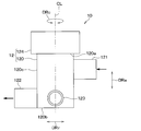
- the valve device 10 shown in FIG. 1 is applied to a fluid circulation circuit that circulates a fluid (cooling water in this example) to a traveling power source, a radiator, or the like, and a fluid that circulates in the fluid circulation circuit flows.
- the valve device 10 can increase or decrease the flow rate of the fluid in the flow path through the valve device 10 in the fluid circulation circuit, and can also block the flow of the fluid in the flow path.
- the fluid for example, LLC containing ethylene glycol is used. LLC is an abbreviation for Long Life Coolant.
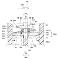
- the valve device 10 has a housing 12 that forms an outer shell.
- the valve device 10 is composed of a three-way valve having an inlet portion 121 for inflowing fluid, a first outlet portion 122 for discharging fluid, and a second outlet portion 123 for discharging fluid in the housing 12.
- the valve device 10 not only functions as a flow path switching valve, but also adjusts the flow rate ratio of the fluid flowing from the inlet portion 121 to the first outlet portion 122 and the fluid flowing from the inlet portion 121 to the second outlet portion 123. It also functions as a flow control valve.
- the valve device 10 is configured as a disc valve that opens and closes a valve by rotating a disk-shaped valve body around the axis CL of the shaft 20, which will be described later.
- the direction along the axis CL of the shaft 20 described later is defined as the axial direction DRa
- the direction orthogonal to the axial direction DRa and extending radially from the axial direction DRa is defined as the radial DRr. Etc. will be explained.
- various configurations and the like will be described with the direction around the axial center CL as the circumferential direction DRc.
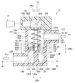
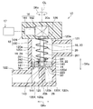
- a stator 14 As shown in FIG. 3, in the valve device 10, a stator 14, a drive unit 16, a rotating unit 18, an urging member 26, and the like are housed inside the housing 12.
- the housing 12 is a non-rotating member that does not rotate.
- the housing 12 is made of, for example, a resin material.
- the housing 12 has a bottomed tubular main body 120 extending along the axial direction DRa and a main body cover 124 that closes the opening 120a of the main body 120.
- the main body 120 has a bottom wall 120b forming the bottom surface and a side wall 120c surrounding the axis CL.
- an inlet portion 121 is formed at a position closer to the opening 120a than the bottom wall portion 120b, and a first outlet portion 122 and a second outlet portion 123 are formed at a position closer to the bottom wall portion 120b than the opening 120a. Is formed.
- an annular protrusion 120d that protrudes so as to approach the axial center CL is formed.
- the protrusion 120d is provided to arrange the stator 14 inside the main body 120.
- the protrusion 120d is provided with a pin for preventing rotation, and the pin regulates the movement of the stator 14 in the circumferential direction DRc.
- the detent of the stator 14 may be realized by means other than the detent pin.
- the inside of the main body 120 is partitioned by a stator 14 into an inlet side space 120e and an exit side space 120f.
- the entrance side space 120e is a space that communicates with the entrance portion 121 inside the housing 12.
- the outlet side space 120f is a space that communicates with the first outlet portion 122 and the second outlet portion 123 inside the housing 12.
- a plate-shaped partition 125 for partitioning the outlet side space 120f into the first outlet side space 120g and the second outlet side space 120h is set inside the main body 120.
- the partition portion 125 is provided so as to cross the outlet side space 120f along the radial direction DRr.
- the stator 14 is made of a material having a small coefficient of linear expansion and excellent wear resistance as compared with the constituent material of the housing 12.
- the stator 14 is made of a high hardness material having a hardness higher than that of the housing 12.
- the stator 14 is made of ceramic. In the stator 14, only the portion forming the opening surface 140 is formed of a material having a small coefficient of linear expansion such as ceramic and excellent wear resistance as compared with the constituent material of the housing 12. May be good.
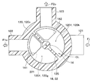
- stator 14 constitutes a flow path forming portion in which a flow path hole through which a fluid passes is formed. As shown in FIG. 4, the stator 14 is formed with a first flow path hole 141 and a second flow path hole 142 through which a fluid passes.
- the first flow path hole 141 and the second flow path hole 142 are formed at positions of the stator 14 away from the axis CL of the shaft 20 so as not to overlap with the axis CL of the shaft 20.
- the first flow path hole 141 and the second flow path hole 142 are sector-shaped (that is, fan-shaped) through holes, and the first flow path hole 141 and the second flow path hole 142 are an inlet side space 120e and an outlet. It functions as a communication passage that communicates with the side space 120f.
- the first flow path hole 141 and the second flow path hole 142 are not limited to the sector shape, and may have other shapes such as a circular shape and an elliptical shape.
- the first flow path hole 141 is provided in a portion of the stator 14 corresponding to the first outlet side space 120 g so as to communicate with the first outlet side space 120 g.
- the second flow path hole 142 is provided in a portion of the stator 14 corresponding to the second outlet side space 120h so as to communicate with the second outlet side space 120h.
- the other end side portion 20b of the shaft 20 is a portion of the shaft 20 that is opposite to the one end side portion 20a to which the rotational force is transmitted from the drive unit 16 in the axial direction DRa.
- the other end side bearing portion 144 that rotatably supports the other end side portion 20b of the shaft 20 is arranged.
- the other end side bearing portion 144 is composed of a slide bearing that receives the other end side portion 20b by the sliding surface.
- the other end side bearing portion 144 may be composed of other bearings such as ball bearings instead of the slide bearings.
- the holding portion is composed of the holding hole 143 and the bearing portion 144 on the other end side.
- the drive unit 16 is a device for outputting a rotational force.
- the drive unit 16 has a motor 161 as a drive source and a gear unit 162 as a power transmission member that transmits the output of the motor 161 to the shaft 20.
- the motor 161 is a drive source that rotates by receiving electric power.
- the motor 161 rotates according to a control signal from the valve control unit 17 electrically connected to the motor 161.
- the valve control unit 17 is a computer having a memory which is a non-transitional substantive storage medium, a processor, and the like.
- the valve control unit 17 executes a computer program stored in the memory and executes various control processes according to the computer program.
- the gear unit 162 has a plurality of gears.
- the gear unit 162 transmits the rotational operation of the motor 161 to the rotating unit 18 by meshing the plurality of gears with each other to rotate the rotating unit 18.
- the gear unit 162 transmits the rotational operation of the motor 161 to the shaft 20 of the rotating unit 18 to rotate the shaft 20 and the rotor 22 constituting the rotating unit 18.
- the gear portion 162 of the present embodiment is composed of a gear mechanism including a helical gear or a spur gear as a gear.
- the gear portion 162 is not limited to the gear mechanism described above, and may be composed of, for example, a worm gear having a worm and a worm wheel as gears.
- the rotating unit 18 rotates about the axis CL of the shaft 20 by the output of the driving unit 16 in the valve device 10.
- the rotating portion 18 has a shaft 20, a rotor 22 as a valve body, and a meson 24 that connects the rotor 22 to the shaft 20.
- one end side portion 20a is rotatably supported by one end side bearing portion 126 provided in the main body cover portion 124, and the other end side portion 20b is rotatably supported by the other end side bearing portion 144.
- the one end side bearing portion 126 is composed of a slide bearing that receives the one end side portion 20a by the sliding surface.
- the one-end side bearing portion 126 may be composed of other bearings such as ball bearings instead of the slide bearings.
- the rotor 22 is a valve body that increases or decreases the opening degree of the first flow path hole 141 and the opening degree of the second flow path hole 142 as the shaft 20 rotates.
- the opening degree of the first flow path hole 141 is the degree to which the first flow path hole 141 is opened, and is represented as 100% when the first flow path hole 141 is fully opened and 0% when the first flow path hole 141 is fully closed.
- Fully opening the first flow path hole 141 is, for example, a state in which the first flow path hole 141 is not blocked by the rotor 22 at all.
- the fully closed first flow path hole 141 is, for example, a state in which the entire first flow path hole 141 is completely closed by the rotor 22.
- the opening degree of the second flow path hole 142 is the same as the opening degree of the first flow path hole 141.
- the rotor 22 is composed of a disk-shaped member whose thickness direction is the axial direction DRa.
- the rotor 22 is arranged in the inlet side space 120e so as to face the stator 14 in the axial direction DRa.
- the rotor 22 has a sliding surface 220 that slides relative to the opening surface 140 of the stator 14.
- the sliding surface 220 is a sealing surface that seals the opening surface 140 of the stator 14.
- the rotor 22 is made of a material having a small coefficient of linear expansion and excellent wear resistance as compared with the constituent material of the housing 12.
- the rotor 22 is made of a high hardness material having a hardness higher than that of the housing 12. Specifically, the rotor 22 is made of ceramic. In the rotor 22, only the portion forming the sliding surface 220 is made of a material having a small coefficient of linear expansion such as ceramic and excellent wear resistance as compared with the constituent material of the housing 12. You may.
- the rotor 22 has a rotor hole 221 formed at a position eccentric with respect to the axial center CL of the shaft 20.
- the rotor hole 221 is a through hole penetrating in the axial direction DRa.
- the rotor hole 221 is located at a portion of the rotor 22 that overlaps the first flow path hole 141 and the second flow path hole 142 in the axial direction DRa when the rotor 22 is rotated around the axis CL of the shaft 20. It is formed.
- valve device 10 when the rotor 22 is rotated so that the rotor hole 221 overlaps the first flow path hole 141 in the axial direction DRa, the first flow path hole 141 is opened. Further, in the valve device 10, when the rotor 22 is rotated so that the rotor hole 221 overlaps the second flow path hole 142 in the axial direction DRa, the second flow path hole 142 is opened.
- the rotor 22 is configured so that the flow rate ratio of the fluid passing through the first flow path hole 141 and the fluid passing through the second flow path hole 142 can be adjusted. That is, the rotor 22 is configured so that the opening degree of the second flow path hole 142 decreases as the opening degree of the first flow path hole 141 increases.
- the meson 24 constitutes a part of the connecting structure for connecting the rotor 22 to the shaft 20.
- the meson 24 also functions as a rotation prevention mechanism for preventing the rotor 22 from rotating.
- the meson 24 connects the rotor 22 to the shaft 20 so that a gap is formed between the other end side portion 20b and the rotor 22.
- the meson 24 is provided at a position closer to the one end side portion 20a in the axial direction DRa than the rotor 22.
- the meson 24 has an intermediate tubular portion 241 that covers the outer periphery of the shaft 20 and an intermediate pin 242 that protrudes from the intermediate tubular portion 241 toward the rotor 22 along the axial direction DRa.
- the intermediate tubular portion 241 is connected to the shaft 20 by a connecting means such as press fitting, fitting, or bonding so that the intermediate tubular portion 241 can rotate integrally with the shaft 20.
- the intermediate pin 242 is a member that transmits the rotation of the shaft 20 to the rotor 22.
- the intermediate pin 242 is configured to be able to be fitted into the pin receiving portion 222 formed on the surface of the rotor 22 on the opposite side of the sliding surface 220.
- the meson 24 configured in this way is configured to prevent the rotor 22 from rotating by fitting the meson pin 242 into the pin receiving portion 222.
- the rotation prevention mechanism of the rotor 22 is not limited to the above-mentioned one, and may be realized by other means.
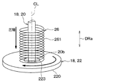
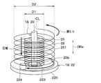
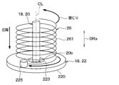
- the urging member 26 is a member that urges the rotor 22 toward the stator 14 corresponding to the flow path forming portion. As shown in FIG. 5, the urging member 26 is composed of a coil-shaped compression spring 261 that applies a compressive load to the rotor 22.
- the compression spring 261 is an elastic member that elastically deforms in the axial direction DRa of the shaft 20.
- the compression spring 261 is formed by being wound around the axis CL of the shaft 20. That is, the shaft 20 is arranged inside the compression spring 261. The compression spring 261 is arranged in a compressed state between the drive unit 16 and the rotor 22.
- the compression spring 261 is inside the housing 12 so that one end of the axial DRa is in contact with the main body cover portion 124 and the other end of the axial DRa is in contact with the rotor 22. Is located in.
- the compression spring 261 is not fixed to at least one of the rotor 22 and the main body cover portion 124 so as not to function as a torsion spring.
- the compression spring 261 employs a spring whose both ends are closed ends so that it is difficult to incline with respect to the axial center CL of the shaft 20.
- the closed-end spring has the end of the spring wire attached to the adjacent winding by changing the winding angle only for the winding at the end of the spring in order to improve the installation of the spring.
- the compression spring 261 may employ a spring having open ends at both ends.
- This contact state is a state in which the opening surface 140 of the stator 14 and the sliding surface 220 of the rotor 22 are in surface contact with each other.
- the contact point where the stator 14 and the rotor 22 are in contact between the first flow path hole 141 and the second flow path hole 142 is defined as the first contact point P1.
- FIG. 6 what is shown in FIG. 6 is a second virtual line VL1 that passes through the first contact P1 and the axial center CL of the shaft 20 and a second virtual line VL1 that is orthogonal to the first virtual line VL1 and passes through the axial center CL of the shaft 20.
- the virtual line VL2 is divided into four areas A1, A2, A3, and A4.
- the contact point where the stator 14 and the rotor 22 are in contact with each other in the third region A3 other than the first region A1 and the second region A2 adjacent to each other via the first contact P1 is the second contact P2.
- the contact point where the stator 14 and the rotor 22 are in contact with each other in the fourth region A4 is the third contact point P3.
- the first contact P1, the second contact P2, and the third contact P3 in which the stator 14 and the rotor 22 are in contact with each other are not limited to those shown in FIG.
- the first contact P1, the second contact P2, and the third contact P3 may be defined based on, for example, the load acting on the stator 14 from the rotor 22 by the urging member 26.
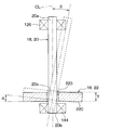
- FIG. 7 is an enlarged partially enlarged view of the VII portion of FIG.
- the connecting structure between the shaft 20 and the rotor 22 includes a fitting structure 28 in which a part of the shaft 20 is fitted into the fitting hole 223 provided in the rotor 22.
- the fitting structure 28 has a fitting structure in which a part of the shaft 20 is gap-fitted with respect to the fitting hole 223 of the rotor 22.
- the shaft 20 of the present embodiment constitutes a fitting portion 20c in which a part of the other end side portion 20b is fitted into the fitting hole 223 provided in the rotor 22.
- the fitting portion 20c is a portion of the other end side portion 20b that overlaps with the rotor 22 in the radial DRr.
- the fitting hole 223 has a size such that a gap is formed between the fitting hole 223 and the shaft 20 so that the shaft 20 can be tilted in a state where a part of the shaft 20 is fitted. That is, the diameter ⁇ g of the fitting hole 223 is larger than the diameter ⁇ s of the fitting portion 20c of the shaft 20 (that is, ⁇ g> ⁇ s).
- the gap between the fitting hole 223 and the fitting portion 20c is larger than the gap between the other end side bearing portion 144 forming the holding portion of the shaft 20 and the fitting portion 20c.
- the fitting dimension difference ⁇ a which is the difference between the diameter ⁇ g of the fitting hole 223 and the diameter ⁇ g of the fitting portion 20c, is the inner diameter ⁇ b of the bearing portion 144 on the other end side and the diameter ⁇ g of the fitting portion 20c. It is larger than the shaft dimensional difference ⁇ b, which is the difference between the two (that is, ⁇ a> ⁇ b).
- the diameter ⁇ g described above cannot be specified. Therefore, for example, when the fitting hole 223 is not circular, the diameter ⁇ g of the fitting hole 223 is set to the diameter of a circle having the same cross-sectional area as the fitting hole 223 (that is, the equivalent diameter), and the above-mentioned magnitude relationship is set. You may be. This also applies to the fitting portion 20c and the bearing portion 144 on the other end side.
- the shaft 20 and the rotor 22 may change from the design target posture shown by the solid line to the tilted posture shown by the broken line due to some factor.
- Factors that cause the shaft 20 and the rotor 22 to tilt include, for example, dimensional variation in the axial direction DRa of the shaft 20, and a structure in which both ends of the shaft 20 are held by separate members. In such a structure, if the assembly accuracy of the main body cover portion 124 and the main body portion 120 is not sufficient, the relative positions of the one end side bearing portion 126 and the other end side bearing portion 144 are displaced in the radial direction DRr, and the shaft 20 is displaced. It tilts.
- valve device 10 of the present embodiment is fitted into the fitting hole 223 of the rotor 22 with a fitting structure in which a part of the shaft 20 is gap-fitted. According to this, it is not necessary to increase the pressing load by the urging member 26, and the increase in the load torque can be suppressed.
- the fitting hole it is desirable that the gap G between the 223 and the fitting portion 20c satisfies the following mathematical formula F1.
- the gap G between the fitting hole 223 and the fitting portion 20c satisfies the following mathematical formula F1
- the opening surface 140 of the stator 14 and the rotor 22 It is possible to make surface contact with the sliding surface 220 of the above.
- the gap G between the fitting hole 223 and the fitting portion 20c is an allowable amount of deviation in the radial DRr between the rotation center of the one end side portion 20a of the shaft 20 and the rotation center of the other end side portion 20b. It may be set to be larger than the deviation amount. This also ensures that the rotor 22 and the stator 14 are in close contact with each other within the design range.
- the fluid flows from the inlet portion 121 into the inlet side space 120e as shown by the arrow Fi.
- the fluid flows from the inlet side space 120e to the first outlet side space 120g via the first flow path hole 141.
- the fluid that has flowed into the first outlet side space 120 g flows out from the first outlet side space 120 g via the first outlet portion 122 to the outside of the valve device 10 as shown by an arrow F1o.
- the flow rate of the fluid passing through the first flow path hole 141 is determined according to the opening degree of the first flow path hole 141. That is, the flow rate of the fluid flowing from the inlet portion 121 to the first outlet portion 122 through the first flow path hole 141 increases as the opening degree of the first flow path hole 141 increases.
- the second flow path hole 142 when the second flow path hole 142 is open, the fluid flows from the inlet side space 120e into the second outlet side space 120h via the second flow path hole 142.
- the fluid that has flowed into the second outlet side space 120h flows out from the second outlet side space 120h to the outside of the valve device 10 via the second outlet portion 123 as shown by the arrow F2o.
- the flow rate of the fluid passing through the second flow path hole 142 is determined according to the opening degree of the second flow path hole 142. That is, the flow rate of the fluid flowing from the inlet portion 121 to the second outlet portion 123 through the second flow path hole 142 increases as the opening degree of the second flow path hole 142 increases.
- the valve device 10 of the present embodiment described above has a connecting structure in which the shaft 20 is tiltably connected to the rotor 22. According to this, even if the shaft 20 is tilted for some reason, it is possible to secure the adhesion between the rotor 22 and the stator 14 constituting the flow path forming portion.
- the posture of the rotor 22 is defined by the pressure of the fluid.
- the posture of the rotor 22 is not determined, and it becomes insufficient to secure the adhesion between the rotor 22 and the stator 14 constituting the flow path forming portion.
- valve device 10 of the present embodiment has a peculiar action and effect that fluid leakage due to a change in the posture of the shaft 20 can be suppressed by the organic coupling between the above-mentioned connecting structure and the urging member 26. Play.
- the connecting structure between the shaft 20 and the rotor 22 includes a fitting structure 28 in which the fitting portion 20c of the shaft 20 is fitted into the fitting hole 223 provided in the rotor 22.
- the fitting hole 223 has a size such that a gap is formed between the fitting hole 223 and the shaft 20 so that the shaft 20 can be tilted while the fitting portion 20c is fitted.
- the fitting structure 28 in which a gap is formed between the fitting hole 223 and the fitting portion 20c the contact between the fitting hole 223 and the fitting portion 20c is suppressed, so that the sliding in the connecting structure It is possible to suppress dynamic loss and ensure wear resistance. That is, the fitting structure 28 can suppress sliding loss and ensure wear resistance as compared with a connecting structure in which members slide with each other like a joint.
- the gap between the fitting hole 223 and the fitting portion 20c is larger than the gap between the other end side bearing portion 144 forming the holding portion of the shaft 20 and the fitting portion 20c.
- the urging member 26 is composed of a compression spring 261 which is an elastic member elastically deformed in the axial direction DRa of the shaft 20. According to this, a sufficient load for pressing the sliding surface 220 of the rotor 22 toward the opening surface 140 of the stator 14 can be sufficiently secured, so that the contact state between the sliding surface 220 and the opening surface 140 is maintained. It will be easier.
- the shaft 20 is arranged inside the compression spring 261. According to this, since the load of the compression spring 261 on the rotor 22 is suppressed from being biased in the circumferential direction DRc of the shaft 20, the contact state between the sliding surface 220 and the opening surface 140 is easily maintained.
- a coil-shaped compression spring 261 is used as the urging member 26, but the urging member 26 is not limited to the compression spring 261.
- the urging member 26 may be composed of a cylindrical elastic body 262 that elastically deforms in the axial direction DRa of the shaft 20.
- the elastic body 262 is made of, for example, a stretchable rubber material.
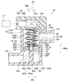
- the shaft 20 is provided with a flange portion 20d protruding in the radial DRr of the shaft 20 at a position closer to one end side portion 20a than the rotor 22.
- the flange portion 20d is formed in a disk shape and is provided with respect to the shaft 20 so as to rotate integrally with the shaft 20.
- the outer diameter of the flange portion 20d is larger than the outer diameter of the compression spring 261.
- the compression spring 261 is arranged in a compressed state between the rotor 22 and the flange portion 20d so as to rotate together with the rotor 22. Specifically, the compression spring 261 is inside the housing 12 so that one end of the axial DRa is in contact with the flange 20d and the other end of the axial DRa is in contact with the rotor 22. Have been placed. The compression spring 261 is not fixed to at least one of the rotor 22 and the main body cover portion 124 so as not to function as a torsion spring.
- valve device 10 of the present embodiment can obtain the same or the same effect as that of the first embodiment.
- the compression spring 261 is arranged in a compressed state between the rotor 22 and the flange portion 20d. According to this, since the compression spring 261 rotates integrally with the rotor 22 and the shaft 20, it is possible to suppress the sliding loss due to the sliding of the compression spring 261 and to secure the wear resistance. Further, since the compression spring 261 does not function as a torsion spring, it is possible to prevent an unnecessary force from acting on the rotor 22 in the circumferential direction around the axial center CL of the shaft 20.
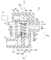
- the valve device 10 includes a coiled torsion spring 29 that urges the rotor 22 on one side of the circumferential DRc around the axial CL of the shaft 20.
- the torsion spring 29 is arranged between the drive unit 16 and the rotor 22.
- the torsion spring 29 is formed by being wound around the axial center CL of the shaft 20.
- the coil diameter D2 of the torsion spring 29 is larger than the coil diameter D1 of the compression spring 261.
- a compression spring 261 is arranged inside the torsion spring 29.
- the torsion spring 29 is fixed to the rotor 22 and the main body cover portion 124, respectively.
- one end side of the axial DRa is connected to the main body cover portion 124 so as not to be relatively rotatable, and the other end side of the axial direction DRa is connected to the rotor 22 so as not to be relatively rotatable.
- Various methods of connecting the torsion spring 29 to the rotor 22 are conceivable.
- the end of the torsion spring 29 is connected to the rotor 22 by being locked to a fixing pin 224 fixed to the rotor 22. To.
- the smaller the coil diameter D the larger the spring constant of the coil spring.
- the spring constant is large, the load acting on the rotor 22 fluctuates greatly. Such load fluctuations can be a factor in deteriorating the adhesion between the rotor 22 and the stator 14.
- valve device 10 of the present embodiment can obtain the same or the same effect as that of the first embodiment.
- the urging member 26 not only urges the rotor 22 toward the stator 14, but also urges the rotor 22 to one side of the circumferential DRc. It is composed of elastic members that are connected together. Specifically, the urging member 26 is composed of a compression spring 261 configured to also function as a torsion spring.
- the compression spring 261 of this embodiment is fixed to each of the rotor 22 and the main body cover portion 124.
- one end side of the axial DRa is connected to the main body cover portion 124 so as not to be relatively rotatable, and the other end side of the axial direction DRa is connected to the rotor 22 so as not to be relatively rotatable.
- Various methods of connecting the compression spring 261 to the rotor 22 are conceivable.
- the end of the compression spring 261 is connected to the rotor 22 by being locked to a fixing pin 225 fixed to the rotor 22. To.
- the compression spring 261 is used in a state of being twisted in the circumferential direction DRc to cause elastic deformation.
- the compression spring 261 generates an urging force that urges the rotor 22 to one side of the circumferential DRc due to its elastic deformation.
- valve device 10 of the present embodiment can obtain the same or the same effect as that of the first embodiment.
- the elastic member has a function as a torsion spring in addition to a function as a compression spring 261. Therefore, the position of the rotor 22 and the shaft 20 are displaced in the circumferential direction DRc of the shaft 20 while maintaining the posture of the rotor 22 in contact with the stator 14 without increasing the number of parts of the valve device 10. Can be suppressed.
- a seal member 30 is arranged between the stator 14 and the housing 12.
- the seal member 30 is interposed between the stator 14 and the protrusion 120d of the housing 12.
- the seal member 30 is configured to be elastically deformable in the axial direction DRa. As shown in FIG. 18, the seal member 30 is composed of a disk-shaped member having the axial direction DRa as the thickness direction. The seal member 30 has an outer diameter equivalent to that of the stator 14 so as to overlap the stator 14 in the axial direction DRa. Further, the thickness of the seal member 30 is smaller than the thickness of the stator 14.
- the seal member 30 is formed with a first through hole 30a through which a fluid passes through a portion facing the first flow path hole 141. Further, the seal member 30 is formed with a second through hole 30b through which a fluid passes through a portion facing the second flow path hole 142.
- valve device 10 of the present embodiment can obtain the same or the same effect as that of the first embodiment.
- the seal member 30 is arranged between the stator 14 and the housing 12. According to this, the sealing property between the stator 14 and the housing 12 can be ensured by the sealing member 30. Further, for example, if the pressure acting on the rotor 22 varies in the circumferential direction DRc, the rotor 22 may be in an inclined posture, but even in this case, the stator 14 is rotated by the deformation of the seal member 30. It is possible to follow the child 22 and tilt it. As described above, according to the configuration in which the seal member 30 is interposed between the stator 14 and the housing 12, the adhesion between the stator 14 and the rotor 22 can be ensured, and fluid leakage in the valve device 10 can be ensured. Can be sufficiently suppressed.
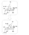
- a universal joint 32 is adopted as the connecting structure between the shaft 20 and the rotor 22.
- the universal joint 32 is a joint capable of changing the joining angle. Specifically, the universal joint 32 connects the shaft 20 and the rotor 22 so that the angle formed by the sliding surface 220 of the rotor 22 and the axial center CL of the shaft 20 can be changed.
- the universal joint 32 is composed of a ball joint 321.
- the ball joint 321 is composed of a ball stud 20e provided on the other end side portion 20b of the shaft 20 and a socket 226 provided on the surface of the rotor 22.
- the ball stud 20e is made of a sphere having a spherical surface.
- the socket 226 has an inner shape corresponding to the spherical surface of the ball stud 20e so as to be in contact with the spherical surface of the ball stud 20e.
- the rotor 22 can rotate together with the shaft 20 due to the frictional force at the time of contact between the ball stud 20e and the socket 226.
- valve device 10 of the present embodiment can obtain the same or the same effect as that of the first embodiment.
- the ball joint 321 of the sixth embodiment described above is exemplified in that the ball stud 20e is provided on the other end side portion 20b of the shaft 20 and the socket 226 provided on the surface of the rotor 22 is provided. Not limited to this.
- the ball joint 321 may be composed of, for example, a socket provided on the other end side portion 20b of the shaft 20 and a ball stud provided on the rotor 22.
- the universal joint 32 of the present embodiment is composed of a universal receiving portion 227 provided on the rotor 22.
- the universal receiving portion 227 is a through hole that penetrates the rotor 22 in the thickness direction.
- the free receiving portion 227 has an arcuate surface 227a having a substantially semicircular cross section that protrudes so as to approach the axial direction DRa.
- the other end side portion 20b of the shaft 20 is supported by the free receiving portion 227 so as to be tiltable, mainly by contacting with the vicinity of the apex 227b of the arcuate surface 227a.
- the rotor 22 can rotate together with the shaft 20 due to the frictional force at the time of contact between the universal receiving portion 227 and the shaft 20.
- valve device 10 of the present embodiment can obtain the same or the same effect as that of the first embodiment.
- the shaft 20 can be tiltably supported by providing the universal receiving portion 227 with respect to the rotor 22.
- the connecting structure of the shaft 20 and the rotor 22 can be realized by a simple structure.
- the temperature control device 1 is mounted on an electric vehicle that obtains driving force for traveling from an electric motor.
- the temperature adjusting device 1 is a device that adjusts the temperature of the blown air into the vehicle interior, which is the space to be air-conditioned, and also adjusts the temperature of a plurality of in-vehicle devices including the battery BT in the electric vehicle.
- the temperature adjusting device 1 can be interpreted as an air conditioner having a temperature adjusting function of an in-vehicle device.
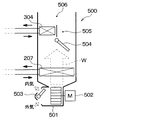
- the temperature control device 1 includes a refrigeration cycle device 200, a first fluid circulation circuit 300, a second fluid circulation circuit 400, an indoor air conditioning unit 500, a control device 600, and the like.
- the refrigeration cycle apparatus 200 constitutes a vapor compression type refrigeration cycle.
- the refrigeration cycle device 200 includes a compressor 201, a radiator 202, a first expansion valve 204, a second expansion valve 205, a chiller 206, an indoor evaporator 207, an evaporation pressure adjusting valve 208, and the like.
- the refrigeration cycle device 200 can switch the circuit configuration of the refrigerant circuit according to various operation modes described later.
- the refrigeration cycle device 200 uses an HFO-based refrigerant (for example, R1234yf) as the refrigerant.
- the refrigeration cycle device 200 constitutes a subcritical refrigeration cycle in which the maximum value of the refrigerant pressure does not exceed the critical pressure of the refrigerant.
- Refrigerant oil for example, PAG oil
- a part of the refrigerating machine oil circulates together with the refrigerant in the refrigerant circuit of the refrigerating cycle device 200.
- the compressor 201 is a device that compresses and discharges the sucked refrigerant.
- the compressor 201 is arranged in the drive system accommodation chamber on the front side of the vehicle.
- the drive system accommodation room is a space in which an electric motor or the like, which is a drive source for traveling, is arranged.
- the drive train containment chamber and the passenger compartment are separated by a fire wall.
- the refrigerant inlet side of the radiator 202 is connected to the refrigerant discharge side.
- the radiator 202 is a heat exchanger that dissipates the refrigerant by exchanging heat between the refrigerant discharged from the compressor 201 and the high-temperature heat medium circulating in the first fluid circulation circuit 300.
- the radiator 202 also functions as a heating heat exchanger that heats the high-temperature heat medium.
- the refrigeration cycle device 200 employs a so-called subcool type heat exchanger as the radiator 202. That is, the radiator 202 is provided with a condensing unit 202a, a receiver unit 202b, and a supercooling unit 202c.
- the condensing unit 202a is a heat exchange unit for condensing that condenses the high-pressure refrigerant by exchanging heat between the refrigerant discharged from the compressor 201 and the high-temperature heat medium.
- the receiver unit 202b is a liquid receiving unit that separates the gas-liquid of the refrigerant flowing out from the condensing unit 202a and stores the separated liquid-phase refrigerant.
- the supercooling unit 202c is a heat exchange unit for supercooling that supercools the liquid phase refrigerant by exchanging heat between the liquid phase refrigerant flowing out from the receiver unit 202b and the high temperature heat medium.
- the refrigerant branch portion 203 is connected to the refrigerant outlet side of the radiator 202.
- the refrigerant branching portion 203 branches the flow of the refrigerant flowing out of the radiator 202.
- the refrigerant branching portion 203 is a three-way joint having three inflow ports communicating with each other. In the refrigerant branching portion 203, one of the three inflow outlets is used as an inflow port, and the remaining two are used as an outflow port.
- the refrigerant inlet side of the chiller 206 is connected to one outlet of the refrigerant branch 203 via the first expansion valve 204.
- the refrigerant inlet side of the indoor evaporator 207 is connected to the other outlet of the refrigerant branch 203 via the second expansion valve 205.
- the first expansion valve 204 is a pressure reducing unit that reduces the pressure of the refrigerant flowing out from one outlet of the refrigerant branching unit 203.
- the first expansion valve 204 is an electric variable throttle mechanism having a valve body that changes the throttle opening degree and an electric actuator (for example, a stepping motor) that displaces the valve body.
- the operation of the first expansion valve 204 is controlled by a control pulse output from the control device 600.
- the second expansion valve 205 is a pressure reducing unit that reduces the pressure of the refrigerant flowing out from the other outlet of the refrigerant branching unit 203.
- the basic configuration of the second expansion valve 205 is the same as that of the first expansion valve 204.
- the first expansion valve 204 and the second expansion valve 205 have a fully open function that functions as a mere refrigerant passage without exerting a refrigerant depressurizing action and a flow rate adjusting action by fully opening the valve opening. Further, the first expansion valve 204 and the second expansion valve 205 have a fully closing function of closing the refrigerant passage by fully closing the valve opening degree.
- the first expansion valve 204 and the second expansion valve 205 can switch the refrigerant circuits in various operation modes by the fully open function and the fully closed function. Therefore, the first expansion valve 204 and the second expansion valve 205 also have a function as a refrigerant circuit switching unit for switching the circuit configuration of the refrigeration cycle device 200.
- the refrigerant inlet side of the chiller 206 is connected to the refrigerant outlet side of the first expansion valve 204.
- the chiller 206 is a heat exchanger that exchanges heat between the low-pressure refrigerant decompressed by the first expansion valve 204 and the low-temperature heat medium that circulates in the second fluid circulation circuit 400.
- the chiller 206 is an evaporation unit that cools a low-temperature heat medium by evaporating a low-pressure refrigerant to exert an endothermic action.
- the chiller 206 in the second fluid circulation circuit 400 is a cooling device that cools the low temperature heat medium.
- One inflow port side of the refrigerant merging portion 209 is connected to the refrigerant outlet side of the chiller 206.
- the refrigerant inlet side of the evaporation pressure adjusting valve 208 is connected to the refrigerant outlet side of the indoor evaporator 207.
- the evaporation pressure adjusting valve 208 is an evaporation pressure adjusting unit that maintains the refrigerant evaporation pressure in the indoor evaporator 207 to be equal to or higher than a predetermined reference pressure.
- the refrigerant merging section 209 joins the flow of the refrigerant flowing out of the chiller 206 and the flow of the refrigerant flowing out of the evaporation pressure adjusting valve 208.
- the refrigerant merging portion 209 is a three-way joint similar to the refrigerant branching portion 203. In the refrigerant merging section 209, two of the three inflow ports are used as inflow ports, and the remaining one is used as the outflow port.
- the refrigerant suction side of the compressor 201 is connected to the outlet of the refrigerant merging portion 209.
- the first fluid circulation circuit 300 is a fluid circulation circuit in which a high-temperature heat medium that is a fluid circulates.
- a high-temperature heat medium that is a fluid circulates.
- an ethylene glycol aqueous solution is used as the high-temperature heat medium.
- a high temperature side pump 301, a radiator 202, a high temperature side radiator 303, a heater core 304, a high temperature side switching valve 310, and the like are arranged.
- the inlet side of the heat medium passage 302 of the radiator 202 is connected to the discharge port of the high temperature side pump 301.
- the high temperature side pump 301 pumps the high temperature heat medium to the heat medium passage 302 of the radiator 202.
- the high temperature side pump 301 is an electric pump whose rotation speed (that is, pumping capacity) is controlled by a control voltage output from the control device 600.
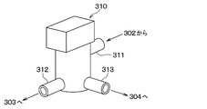
- the inlet portion 311 of the high temperature side switching valve 310 is connected to the downstream side of the electric heater 306.
- the high temperature side switching valve 310 adjusts the flow rate ratio of the high temperature heat medium flowing into the high temperature side radiator 303 and the high temperature heat medium flowing into the heater core 304.
- the high temperature side switching valve 310 constitutes the valve device of the present disclosure.
- the high temperature side switching valve 310 has the same configuration as the valve device 10 described in the first embodiment.
- the first outlet portion 312 is connected to the fluid inlet side of the high temperature side radiator 303, and causes the high temperature heat medium to flow out to the high temperature side radiator 303.
- the first outlet portion 312 corresponds to the first outlet portion 122 in the valve device 10 of the first embodiment.
- the inlet portion 311 is connected to the fluid outlet side of the high temperature side radiator 303 and the fluid outlet side of the heater core 304, and the high temperature heat medium flows in from the high temperature side radiator 303 and the heater core 304.
- the inlet portion 311 corresponds to the inlet portion 121 in the valve device 10 of the first embodiment.
- the high temperature side switching valve 310 has a configuration in which the flow rate ratio of the high temperature heat medium passing through the high temperature side radiator 303 and the high temperature heat medium passing through the heater core 304 is adjusted by rotationally displacing the rotor 22. Specifically, the high-temperature side switching valve 310 increases or decreases the opening degree of the first flow path hole 141 and the opening degree of the second flow path hole 142 by the rotor 22, so that the high-temperature heat passes through the high-temperature side radiator 303. The flow rate ratio of the medium and the high temperature heat medium passing through the heater core 304 is adjusted.
- the high-temperature side radiator 303 is an outdoor heat exchanger that exchanges heat between the high-temperature heat medium heated by the radiator 202 and the like and the air outside the vehicle interior (that is, the outside air OA) blown from an outside air fan (not shown). Is.
- the high temperature side radiator 303 is arranged on the front side of the drive system accommodation chamber. When the vehicle is running, the high temperature side radiator 303 can be exposed to the running wind (that is, the outside air OA) that has flowed into the drive system accommodation chamber via the grill.
- One inflow port side of the high temperature side merging portion 307 is connected to the fluid outlet side of the high temperature side radiator 303.
- the heater core 304 is an indoor heat exchanger that heats the blown air W by exchanging heat between the high-temperature heat medium heated by the radiator 202 or the like and the blown air W blown into the room.
- the heater core 304 is arranged in the casing 501 of the indoor air conditioning unit 500.
- the blown air W is heated by using the heat absorbed by the refrigerant in the chiller 206 as a heating source.
- the other inlet side of the high temperature side merging portion 307 is connected to the fluid outlet side of the heater core 304.
- the high temperature side reserve tank 308 is a storage unit for the high temperature heat medium that stores the high temperature heat medium that is surplus in the first fluid circulation circuit 300.
- the high temperature side reserve tank 308 has a heat medium supply port for replenishing the high temperature heat medium when the amount of the high temperature heat medium circulating in the first fluid circulation circuit 300 is insufficient.
- the second fluid circulation circuit 400 is a fluid circulation circuit in which a low-temperature heat medium that is a fluid circulates.
- a heat medium of the same type as the high temperature heat medium is used as the low temperature heat medium.
- the low temperature side pump 401 In the second fluid circulation circuit 400, the low temperature side pump 401, the heat medium passage 402 of the chiller 206, the low temperature side radiator 403, the flow path switching valve 70, the cooling water passage 405 of the battery BT, the cooling water passage 406 of the in-vehicle device CE, etc. Is placed.
- a low temperature heat medium is connected to the fluid outlet side of the low temperature side pump 401 to the inlet side of the heat medium passage 402 of the chiller 206.
- the low temperature side pump 401 is a pumping unit that pumps the low temperature heat medium to the heat medium passage 402 of the chiller 206.
- the basic configuration of the low temperature side pump 401 is the same as that of the high temperature side pump 301.
- the first inlet portion 700A side of the flow path switching valve 70 is connected to the fluid outlet side of the heat medium passage 402 of the chiller 206.
- the flow path switching valve 70 is a circuit switching unit that switches the circuit configuration of the second fluid circulation circuit 400.
- the flow path switching valve 70 is provided with a plurality of inlet portions and a plurality of outlet portions.
- a cooling water passage 405 of the battery BT, a low temperature radiator 403, and the like are connected to these inlets and outlets. The detailed configuration of the flow path switching valve 70 will be described later.
- the battery BT supplies electric power to the electric in-vehicle device CE such as an electric motor.
- the battery BT is an assembled battery formed by electrically connecting a plurality of battery cells in series or in parallel.
- the battery cell is composed of a rechargeable secondary battery (for example, a lithium ion battery).
- the battery BT is a battery BT in which a plurality of battery cells are stacked and arranged so as to have a substantially rectangular parallelepiped shape and housed in a special case.
- the temperature of the battery BT is maintained within an appropriate temperature range (for example, 15 ° C. or higher and 55 ° C. or lower) so that the charge / discharge capacity of the battery BT can be fully utilized.
- the passage configuration of the cooling water passage 405 of the battery BT is a passage configuration in which a plurality of passages are connected in parallel inside the dedicated case.
- the cooling water passage 405 of the battery BT is formed so as to be able to absorb heat evenly from the entire area of the battery BT.
- the cooling water passage 405 is formed so that the heat of all the battery cells can be uniformly absorbed and all the battery cells can be cooled.
- One inflow port side of the low temperature side confluence 407 is connected to the heat medium outlet of the low temperature side radiator 403 via the low temperature side reserve tank 408.
- the low temperature side reserve tank 408 is a storage unit for the low temperature heat medium that stores the low temperature heat medium that is surplus in the second fluid circulation circuit 400.
- the basic configuration of the low temperature side reserve tank 408 is the same as that of the high temperature side reserve tank 308.
- the low temperature side merging portion 407 is a three-way joint similar to the high temperature side merging portion 307 and the like.
- the second fluid circulation circuit 400 is connected to the equipment cooling passage 410 in which the cooling water passage 406 of the in-vehicle equipment CE is arranged.
- the equipment cooling passage 410 is connected so as to return the low-temperature heat medium on the downstream side of the low-temperature side reserve tank 408 and on the upstream side of the low-temperature side confluence portion 407 to the inlet side of the low-temperature side radiator 403 again. There is.
- the equipment pump 411 is arranged in the equipment cooling passage 410.
- the equipment pump 411 pumps the low temperature heat medium to the cooling water passage 406 of the vehicle-mounted equipment CE.
- the basic configuration of the equipment pump 411 is the same as that of the low temperature side pump 401.
- the in-vehicle device CE is a heat generating device that generates heat when operated.
- the in-vehicle device CE is an electric motor, an inverter, a control device for an advanced driving system, and the like.
- An electric motor is an in-vehicle device that outputs a driving force for traveling.
- An inverter is an in-vehicle device that supplies electric power to an electric motor.
- the control device for advanced driver assistance systems is a control device for so-called ADAS.
- ADAS is an abbreviation for Advanced Driver Assistance System.
- a cooling water passage 406 for circulating a low temperature heat medium is formed inside the housing portion or the case forming the outer shell of the in-vehicle device CE.
- the cooling water passage 406 is an endothermic heat medium passage for absorbing the heat of the vehicle-mounted device CE (that is, the waste heat of the vehicle-mounted device CE) into the low-temperature heat medium.
- the cooling water passage 406 constitutes a temperature control unit that adjusts the temperature of the in-vehicle device CE, which is a heat generating device.
- a detour passage 420 for equipment is connected to the second fluid circulation circuit 400.
- the device bypass passage 420 is a heat medium passage that bypasses the low-temperature heat medium flowing out of the cooling water passage 406 of the in-vehicle device CE and returns it to the fluid inlet side of the device pump 411 by bypassing the low-temperature side radiator 403 and the like.
- the device bypass passage 420 constitutes a bypass portion for passing a low-temperature heat medium by bypassing the low-temperature side radiator 403, which is an outdoor heat exchanger.
- the equipment flow rate adjusting valve 412 is arranged on the upstream side of the connection portion with the equipment detour passage 420.
- the equipment flow rate adjusting valve 412 is an electric flow rate adjusting valve having a valve body that changes the passage cross-sectional area of the equipment cooling passage 410 and an electric actuator (for example, a stepping motor) that displaces the valve body.
- the operation of the flow control valve 412 for equipment is controlled by a control pulse output from the control device 600.
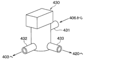
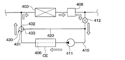
- a low temperature side switching valve 430 is arranged at the connection portion between the equipment cooling passage 410 and the equipment detour passage 420.
- the low temperature side switching valve 430 adjusts the flow rate ratio between the low temperature heat medium flowing into the low temperature side radiator 403 and the low temperature heat medium flowing into the equipment bypass passage 420.
- the low temperature side switching valve 430 constitutes the valve device of the present disclosure in the same manner as the high temperature side switching valve 310.
- the low temperature side switching valve 430 has the same configuration as the valve device 10 described in the first embodiment.
- the first outlet portion 432 is connected to the fluid inlet side of the low temperature side radiator 403, and causes the low temperature heat medium to flow out to the low temperature side radiator 403.
- the first outlet portion 432 corresponds to the first outlet portion 122 in the valve device 10 of the first embodiment.
- the inlet portion 431 is connected to the fluid outlet side of the cooling water passage 406 of the in-vehicle device CE, which is a temperature control portion, and the fluid that has passed through the cooling water passage 406 flows in.
- the inlet 431 corresponds to the inlet 121 in the valve device 10 of the first embodiment.
- the low temperature side switching valve 430 has a configuration in which the flow rate ratio of the low temperature heat medium passing through the low temperature side radiator 403 and the low temperature heat medium passing through the device bypass passage 420 is adjusted by rotationally displacing the rotor 22. There is. Specifically, the low temperature side switching valve 430 increases or decreases the opening degree of the first flow path hole 141 and the opening degree of the second flow path hole 142 by the rotor 22, so that the low temperature heat passes through the low temperature side radiator 403. The flow rate ratio of the medium and the low temperature heat medium passing through the device bypass passage 420 is adjusted.
- the operation of the low temperature side switching valve 430 is controlled by the control pulse output from the control device 600.
- the control device 600 also has a function as the valve control unit 17 described in the first embodiment.
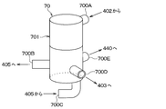
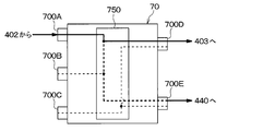
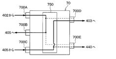
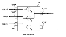
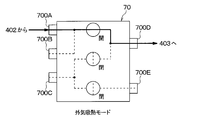
- a short-circuit heat medium passage that guides the low-temperature heat medium flowing out from the third outlet portion 700E of the flow path switching valve 70 to the other inflow port of the low-temperature side merging portion 407. 440 is connected.
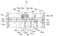
- the flow path switching valve 70 has a resin main body portion 701 formed in a bottomed tubular shape.
- the main body 701 is a housing having a plurality of inlet portions for flowing the low temperature heat medium into the inside and a plurality of outlet portions for allowing the low temperature heat medium to flow out from the inside.
- the main body portion 701 of the present embodiment has two inlet portions and three outlet portions. Therefore, the flow path switching valve 70 is a five-way valve having five entrances and exits.
- the flow path switching valve 70 is provided with a first inlet portion 700A and a second inlet portion 700C.
- the first inlet portion 700A is a low-temperature heat medium pumped from the low-temperature side pump 401, and is an inlet portion through which the low-temperature heat medium that has passed through the heat medium passage 402 of the chiller 206 flows in.
- the second inlet portion 700C is an inlet portion through which the low-temperature heat medium flowing out from the cooling water passage 405 of the battery BT flows in.
- the flow path switching valve 70 is provided with a first outlet portion 700B, a second outlet portion 700D, and a third outlet portion 700E.
- the first outlet portion 700B is an outlet portion that allows the low temperature heat medium to flow out to the fluid inlet side of the cooling water passage 405 of the battery BT.
- the second outlet portion 700D is an outlet portion that allows the low temperature heat medium to flow out to the fluid inlet side of the low temperature side radiator 403.
- the third outlet portion 700E is an outlet portion that allows the low temperature heat medium to flow out to the fluid inlet side of the heat medium passage 402 of the chiller 206 (that is, to the short circuit heat medium passage 440).
- the cooling water passage 405 of the battery BT is arranged in the heat medium passage from the first outlet portion 700B to the second inlet portion 700C.
- the cooling water passage 405 of the battery BT is arranged in the heat medium passage from the first outlet portion 700B to the second inlet portion 700C.
- the second inlet portion 700C serves as an inlet portion for allowing the low-temperature heat medium that has flowed out from the first outlet portion 700B to the outside of the main body portion 701 to flow into the inside again.
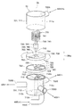
- the main body 701 of the flow path switching valve 70 is divided into a first main body 711 and a second main body 712. Both the first main body portion 711 and the second main body portion 712 are formed in a cylindrical shape and are arranged coaxially. One end side of the first main body portion 711 in the axial direction DRa is closed by the lid portion, and the other end side is open. The other end side of the second main body portion 712 in the axial direction DRa is closed by the bottom portion, and one end side is open.
- a stator 720 is arranged inside the main body 701.
- the stator 720 is arranged near the connection portion between the first main body portion 711 and the second main body portion 712.
- a plurality of spaces are formed inside the main body 701 by the stator 720.
- the first entrance side space 711a is formed inside the first main body portion 711.
- the first entrance side space 711a is a substantially columnar space communicating with the first entrance portion 700A.
- a first outlet side space 712b, a second entrance side space 712c, a second exit side space 712d, and a third exit side space 712e are formed inside the second main body portion 712.
- a plurality of partition plates 713 extending radially from the axis CL of the shaft 740 are arranged inside the second main body portion 712.
- the partition plate 713 divides the internal space of the second main body portion 712 into a plurality of spaces in the circumferential direction DRc.
- the first exit side space 712b is a space communicating with the first exit portion 700B.
- the second entrance side space 712c is a space communicating with the second entrance portion 700C.
- the second exit side space 712d is a space communicating with the second exit portion 700D.
- the third exit side space 712e is a space communicating with the third exit portion 700E.
- the first exit-side space 712b, the second inlet-side space 712c, the second exit-side space 712d, and the third exit-side space 712e are all formed in a sector-like (that is, fan-like) cross section in the axial direction DRa. It is a columnar space that extends.
- the first exit side space 712b, the third exit side space 712e, the second entrance side space 712c, and the second exit side space 712d are in this order when viewed from the first main body portion 711 side toward the axial direction DRa. It is arranged clockwise. That is, the second entrance side space 712c is arranged so as to be adjacent to both the second exit side space 712d and the third exit side space 712e in the circumferential direction DRc.
- the stator 720 is a member corresponding to the stator 14 of the valve device 10 of the first embodiment.
- the constituent materials and the like of the stator 720 are the same as those of the stator 14 of the first embodiment.
- the stator 720 is composed of a disk-shaped member whose thickness direction is the axial direction DRa.
- the stator 720 has an opening surface 721 as a surface on which the rotor 750, which will be described later, slides.
- the opening surface 721 is a sealing surface corresponding to the sliding surface 751 of the rotor 750, which will be described later.
- the stator 720 constitutes a flow path forming portion in which a flow path hole through which a fluid passes is formed.
- the stator 720 is formed with a first flow path hole 722, a second flow path hole 723, a third flow path hole 724, and a fourth flow path hole 725 through which the fluid passes.
- the first flow path hole 722 is provided in a portion of the stator 720 corresponding to the first outlet side space 712b so as to communicate with the first outlet side space 712b.
- the second flow path hole 723 is provided in a portion of the stator 720 corresponding to the second inlet side space 712c so as to communicate with the second inlet side space 712c.
- the third flow path hole 724 is provided in a portion of the stator 720 corresponding to the second outlet side space 712d so as to communicate with the second outlet side space 712d.
- the fourth flow path hole 725 is provided in a portion of the stator 720 corresponding to the third outlet side space 712e so as to communicate with the third outlet side space 712e.
- a holding hole 726 for holding the other end side portion 742 of the shaft 740 is formed in the substantially central portion of the stator 720.
- the other end side portion 742 of the shaft 740 is a portion of the shaft 740 that is opposite to the one end side portion 741 in which the rotational force is transmitted from a drive portion (not shown) in the axial direction DRa.
- the holding hole 726 is provided with a bearing portion on the other end side that rotatably supports the other end side portion 742 of the shaft 740.
- the flow path switching valve 70 includes a holding portion of the shaft 740 by a holding hole 726 and a bearing portion on the other end side (not shown).
- the drive unit is a device for outputting rotational force.
- the drive unit is a device corresponding to the drive unit 16 of the valve device 10 of the first embodiment.
- the drive unit of the present embodiment is configured in the same manner as the drive unit 16 of the first embodiment.
- the shaft 740 is a rotating shaft that rotates around a predetermined axial center CL by the rotational force output by the drive unit.
- the shaft 740 extends along the axial direction DRa.
- the shaft 740 has one end side portion 741 in which the rotational force is transmitted from the drive portion to one side in the axial direction DRa and the other end side portion 742 which is opposite to the one end side portion 741 in the axial direction DRa. ..
- the other end side portion 742 is connected to the rotor 750 via a meson 760 so as to be relatively non-rotatable.
- the rotor 750 is a valve body that increases or decreases the opening degree of each flow path hole 722 to 725 formed in the stator 720 as the shaft 740 rotates.
- the rotor 750 is a member corresponding to the rotor 22 of the valve device 10 of the first embodiment.
- the constituent materials and the like of the rotor 750 are the same as those of the rotor 22 of the first embodiment.
- the rotor 750 is arranged in the first entrance side space 711a so as to face the stator 14 in the axial direction DRa.
- the rotor 750 has a sliding surface 751 that slides relative to the opening surface 721 of the stator 720.
- the sliding surface 751 is a sealing surface that seals the opening surface 721 of the stator 720.
- the rotor 750 is formed with a rotor hole 752 at a position eccentric with respect to the axial center CL of the shaft 20.
- the rotor hole 752 is a through hole penetrating in the axial direction DRa.
- the rotor hole 752 is formed at a portion of the rotor 750 that overlaps with each of the flow path holes 722 to 725 in the axial direction DRa when the rotor 750 is rotated.
- the rotor 750 has a fitting hole 753 formed in a substantially central portion thereof.
- the fitting hole 753 is a through hole for fitting the fitting portion 743 of the shaft 740.
- the diameter of the fitting hole 753 is larger than the diameter of the fitting portion 743.
- the meson 760 is a member that connects the rotor 750 to the shaft 740, and constitutes a part of the connecting structure that connects the rotor 750 to the shaft 740.
- the meson 760 is configured in the same manner as the meson 24 of the valve device 10 of the first embodiment.
- the urging member 770 is a member that urges the rotor 22 toward the stator 14 corresponding to the flow path forming portion.
- the urging member 770 is configured in the same manner as the urging member 26 of the valve device 10 of the first embodiment.
- the rotor 750 is rotationally displaced so that the first inlet side space 711a is passed through the rotor hole 752 and one of the flow path holes 723, 724, 725. It can communicate with any of the outlet side spaces 712b, 712d, and 712e. That is, the flow path switching valve 70 rotates and displaces the rotor 750 to allow the low-temperature heat medium flowing in from the first inlet portion 700A to flow out from any one of the plurality of outlet portions 700B, 700D, and 700E. Can be done.
- the flow path switching valve 70 rotates the rotor 750 to rotate and displace the first inlet side space 711a, the first outlet side space 712b, the second outlet side space 712d, and the third outlet side space. It can communicate with any one of the 712e.
- the low-temperature heat medium flowing in from the first inlet portion 700A has a passage configuration in which it flows out from the first outlet portion 700B, a passage configuration in which it flows out from the second outlet portion 700D, and a passage configuration in which it flows out from the third outlet portion 700E. It is possible to switch to any one passage configuration.
- the second inlet side space 712c can be communicated with any one of the plurality of outlet side spaces via the communication groove 754.
- the outlet side space for communicating the first inlet side space 711a and the outlet side space 712c for communicating with the second entrance side space 712c are communicated with each other.
- the side space is a different space.
- the second inlet side space 712c can be communicated with any one of the second outlet side space 712d and the third outlet side space 712e. ..
- the low-temperature heat medium flowing in from the second inlet portion 700C can be switched to any one of a passage configuration in which the low-temperature heat medium flows out from the second outlet portion 700D and a passage configuration in which the low-temperature heat medium flows out from the third outlet portion 700E. ..
- the low-temperature heat medium shaft 740 flowing into the second inlet side space 712c is uniaxially oriented from the other side to one side.
- the flow toward is turned in the opposite direction at the communication groove 754.
- the low temperature heat medium flows from one side to the other side in the axial direction DRa of the shaft 740.
- This also applies to the passage configuration in which the low-temperature heat medium flowing in from the second inlet portion 700C is discharged from the third outlet portion 700E.
- the rotor 750 is formed on opposite sides to each other. Therefore, the rotor 750 is arranged inside the main body 701, which is a housing, so that the pressure Ps1 of the first inlet side space 711a and the pressure Ps2 of the second inlet side space 712c act in opposite directions. become.
- the flow path switching valve 70 can allow the low-temperature heat medium flowing into the inside from the first inlet portion 700A to flow out from the first outlet portion 700B.
- the low-temperature heat medium flowing into the inside from the second inlet portion 700C is discharged from the second outlet portion 700D and the third outlet portion 700E. It is possible to switch between the passage configuration.
- the indoor air conditioning unit 500 is a unit for blowing out appropriately temperature-controlled blown air W to an appropriate location in the vehicle interior in the temperature adjusting device 1.
- the indoor air conditioning unit 500 is arranged inside the instrument panel (that is, the instrument panel) at the frontmost part of the vehicle interior.
- the indoor air conditioning unit 500 has a casing 501 that forms an air passage for the blown air W.
- An indoor blower 502, an indoor evaporator 207, a heater core 304, and the like are arranged in the air passage formed in the casing 501.
- the casing 501 is made of a resin (for example, polypropylene) having a certain degree of elasticity and excellent strength.
- An inside / outside air switching device 503 is arranged on the most upstream side of the blown air flow of the casing 501.
- the inside / outside air switching device 503 switches and introduces the air inside the vehicle interior (that is, the inside air) and the air outside the vehicle interior (that is, the outside air) into the casing 501.
- the operation of the electric actuator for driving the inside / outside air switching device 503 is controlled by the control signal output from the control device 600.
- An indoor blower 502 is arranged on the downstream side of the blower air flow of the inside / outside air switching device 503.
- the indoor blower 502 blows the air sucked through the inside / outside air switching device 503 toward the vehicle interior.
- the indoor blower 502 is an electric blower that drives a fan with an electric motor.
- the rotation speed (that is, the blowing capacity) of the indoor blower 502 is controlled by the control voltage output from the control device 600.
- the air mix door 504 is arranged on the downstream side of the blast air flow of the indoor evaporator 207 and on the upstream side of the blast air flow of the heater core 304.
- the air mix door 504 adjusts the air volume ratio between the air volume passing through the heater core 304 and the air volume passing through the cold air bypass passage 505 in the blown air W after passing through the indoor evaporator 207.
- the operation of the electric actuator for driving the air mix door is controlled by a control signal output from the control device 600.
- a mixing space 506 is provided on the downstream side of the blown air flow of the heater core 304 to mix the blown air W heated by the heater core 304 and the blown air W not heated by the heater core 304 through the cold air bypass passage 505. Has been done. Further, an opening hole (not shown) for blowing out the air-conditioned air mixed in the mixing space 506 into the vehicle interior is arranged at the most downstream portion of the blown air flow of the casing 501.
- the temperature of the conditioned air mixed in the mixing space 506 can be adjusted by adjusting the ratio of the air volume through which the air mix door 504 passes through the heater core 304 and the air volume passing through the cold air bypass passage 505. .. Then, the temperature of the blown air W blown out from each opening hole into the vehicle interior can be adjusted.
- the opening holes As the opening holes, a face opening hole, a foot opening hole, and a defroster opening hole (none of which are shown) are provided.
- the face opening hole is an opening hole for blowing air-conditioning air toward the upper body of the occupant in the vehicle interior.
- the foot opening hole is an opening hole for blowing air-conditioning air toward the feet of the occupant.
- the defroster opening hole is an opening hole for blowing air-conditioning air toward the inner surface of the window glass on the front surface of the vehicle.
- a blowout mode switching door (not shown) is arranged on the upstream side of these opening holes.
- the blow-out mode switching door switches the opening holes for blowing out the air-conditioning air by opening and closing each opening hole.
- the operation of the electric actuator for driving the blowout mode switching door is controlled by a control signal output from the control device 600.
- a control sensor group 610 is connected to the input side of the control device 600.
- the control sensor group 610 includes an internal air temperature detection unit that detects the vehicle interior temperature (internal air temperature) Tr, a battery temperature detection unit that detects the temperature of the battery BT, and an in-vehicle device temperature detection unit that detects the temperature of the in-vehicle device CE. Etc. are included.
- the equipment cooling mode is an operation mode in which the refrigerating cycle device 200 is operated to air-condition the vehicle interior and the battery BT is cooled by the low-temperature heat medium cooled by the refrigerating cycle device 200. ..
- the control device 600 operates the compressor 201, the high-pressure refrigerant discharged from the compressor 201 flows into the radiator 202.
- the control device 600 adjusts the refrigerant discharge capacity of the compressor 201 so that the temperature of the blown air W cooled by the indoor evaporator 207 becomes the target evaporator temperature TEO.
- the target evaporator temperature TEO is determined based on the detection signal of the sensor group 610 connected to the control device 600 with reference to the control map stored in the control device 600 in advance.
- This control map is configured so that the target evaporator temperature TEO is equal to or higher than the frost formation suppression temperature (for example, 1 ° C.) in order to suppress the frost formation of the indoor evaporator 207.
- the flow of the refrigerant flowing out of the radiator 202 is branched at the refrigerant branching portion 203.
- One of the refrigerants branched at the refrigerant branching portion 203 is depressurized by the first expansion valve 204 and flows into the chiller 206.
- the control device 600 adjusts the throttle opening of the first expansion valve 204 so that the temperature of the low-temperature heat medium flowing out of the heat medium passage 402 of the chiller 206 approaches the target cooling temperature TBO.
- the other refrigerant branched at the refrigerant branching portion 203 is depressurized by the second expansion valve 205 and flows into the indoor evaporator 207.
- the control device 600 adjusts the throttle opening of the second expansion valve 205 so that the refrigerant sucked into the compressor 201 approaches a predetermined standard superheat degree KSH (for example, 5 ° C.). Therefore, in the equipment cooling mode, the refrigerant evaporation temperature in the indoor evaporator 207 and the refrigerant evaporation temperature in the chiller 206 may be the same.
- the refrigerant flowing into the indoor evaporator 207 absorbs heat from the blown air W blown from the indoor blower 502 and evaporates. As a result, the blown air W is cooled.
- the refrigerant flowing out of the indoor evaporator 207 flows into the refrigerant merging portion 209 via the evaporation pressure adjusting valve 208.
- the refrigerant merging section 209 merges the flow of the refrigerant flowing out of the indoor evaporator 207 and the flow of the refrigerant flowing out of the chiller 206, and causes the flow out to the suction side of the compressor 201.
- the control device 600 when the control device 600 operates the high temperature side pump 301, the high temperature heat medium pumped from the high temperature side pump 301 flows into the heat medium passage 302 of the radiator 202.
- the high-temperature heat medium flowing into the heat medium passage 302 exchanges heat with the high-pressure refrigerant and is heated.
- the high-temperature heat medium flowing out of the radiator 202 flows into the high-temperature side switching valve 310 and is divided into a flow that flows into the high-temperature side radiator 303 and a flow that flows from the high-temperature side switching valve 310 into the heater core 304.
- the high-temperature heat medium that has flowed into the high-temperature side radiator 303 exchanges heat with the outside air OA blown from the outside air fan and dissipates heat. As a result, the high-temperature heat medium flowing through the high-temperature side radiator 303 is cooled. The high-temperature heat medium flowing out of the high-temperature side radiator 303 flows into the high-temperature side confluence portion 307.
- the high-temperature heat medium that has flowed into the heater core 304 exchanges heat with the blown air W that has passed through the indoor evaporator 207 and dissipates heat.
- the blown air W cooled by the indoor evaporator 207 is reheated.
- the control device 600 adjusts the opening degree of the air mix door 504 so that the blowing temperature of the blowing air W blown into the vehicle interior approaches the target blowing temperature TAO.
- the high-temperature heat medium flowing out of the heater core 304 flows into the high-temperature side merging portion 307.
- the high-temperature side merging portion 307 merges the high-temperature heat medium flowing out from the heater core 304 and the high-temperature heat medium flowing out from the high-temperature side radiator 303, and causes them to flow out to the fluid suction side of the high-temperature side pump 301.
- the low-temperature heat medium flowing out of the chiller 206 flows into the inside from the first inlet portion 700A of the flow path switching valve 70 and flows out from the first outlet portion 700B.
- the low-temperature heat medium flowing out from the first outlet portion 700B flows into the cooling water passage 405 of the battery BT.
- the heat medium that has flowed into the cooling water passage 405 of the battery BT absorbs the waste heat of the battery BT when flowing through the cooling water passage 405. As a result, the battery BT is cooled.
- the low-temperature heat medium flowing out from the cooling water passage 405 of the battery BT flows into the inside from the second inlet portion 700C of the flow path switching valve 70 and flows out from the third outlet portion 700E.
- the low-temperature heat medium flowing out from the third outlet portion 700E is guided to the suction side of the low-temperature side pump 401 via the short-circuit heat medium passage 440 and the low-temperature side merging portion 407.
- the low temperature heat medium discharged from the low temperature side pump 401 passes through the heat medium passage 402 of the chiller 206 and is passed through the flow path switching valve 70. It flows into the first entrance portion 700A of.
- the low-temperature heat medium that has flowed into the first inlet portion 700A of the flow path switching valve 70 flows out from the first outlet portion 700B of the flow path switching valve 70, and then flows out through the cooling water passage 405 of the battery BT, and then the flow path switching valve 70. It flows into the second entrance portion 700C of.
- the low-temperature heat medium that has flowed into the second inlet portion 700C flows out from the second outlet portion 700D of the flow path switching valve 70, and is then sucked into the low-temperature side pump 401 again via the low-temperature side radiator 403.
- the high-pressure refrigerant discharged from the compressor 201 is cooled by the radiator 202 until it becomes a supercooled liquid-phase refrigerant, as in the equipment cooling mode. Further, the high temperature heat medium flowing through the heat medium passage 302 of the radiator 202 is heated.
- the refrigerant flowing out of the radiator 202 flows into the refrigerant branching portion 203.
- the refrigerant flowing into the refrigerant branch portion 203 is depressurized by the second expansion valve 205 and flows into the indoor evaporator 207.
- the control device 600 adjusts the throttle opening degree of the second expansion valve 205 in the same manner as in the equipment cooling mode.
- the low-pressure refrigerant that has flowed into the indoor evaporator 207 absorbs heat from the blown air W and evaporates, as in the equipment cooling mode. As a result, the blown air W is cooled.
- the refrigerant flowing out of the indoor evaporator 207 is sucked into the compressor 201 via the evaporation pressure adjusting valve 208 and the refrigerant merging portion 209.
- the control device 600 controls the operation of the constituent equipment in the same manner as in the equipment cooling mode.
- the outlet side heat medium temperature THC of the high temperature heat medium approaches the reference outlet side heat medium temperature KTHC.
- the control device 600 operates the low temperature side pump 401
- the low temperature heat medium pumped from the low temperature side pump 401 flows into the heat medium passage 402 of the chiller 206.
- the first expansion valve 204 since the first expansion valve 204 is in the fully closed state, the low temperature heat medium flowing into the heat medium passage 402 of the chiller 206 flows out without exchanging heat with the low pressure refrigerant.
- the low-temperature heat medium flowing out of the chiller 206 flows into the inside from the first inlet portion 700A of the flow path switching valve 70 and flows out from the first outlet portion 700B.
- the low-temperature heat medium flowing out from the first outlet portion 700B flows into the cooling water passage 405 of the battery BT.
- the heat medium that has flowed into the cooling water passage 405 of the battery BT absorbs the waste heat of the battery BT when flowing through the cooling water passage 405. As a result, the battery BT is cooled.
- the low-temperature heat medium flowing out of the cooling water passage 405 of the battery BT flows into the inside from the second inlet portion 700C of the flow path switching valve 70 and flows out from the second outlet portion 700D.
- the low temperature heat medium flowing out from the second outlet portion 700D flows into the low temperature side radiator 403.
- the low-temperature heat medium that has flowed into the low-temperature side radiator 403 is blown from the outside air fan and exchanges heat with the outside air OA after passing through the high-temperature side radiator 303 to dissipate heat. As a result, the low temperature heat medium flowing through the low temperature side radiator 403 is cooled. The low-temperature heat medium flowing out of the low-temperature side radiator 403 is guided to the suction side of the low-temperature side pump 401 via the low-temperature side merging portion 407.
- the blown air W cooled by the indoor evaporator 207 can be reheated by the heater core 304 and blown out into the vehicle interior by operating as described above. Therefore, as in the equipment cooling mode, the blown air W adjusted to an appropriate temperature can be blown out into the vehicle interior to realize comfortable air conditioning. Further, in the outside air cooling mode, the battery BT can be cooled by allowing the low temperature heat medium cooled by exchanging heat with the outside air in the low temperature side radiator 403 to flow into the cooling water passage 405 of the battery BT.
- the control device 600 causes the low temperature heat medium flowing in from the first inlet portion 700A to flow out from the third outlet portion 700E. May be good. According to this, the low temperature heat medium flowing out from the heat medium passage 402 of the chiller 206 can be returned to the suction side of the low temperature side pump 401 via the short circuit heat medium passage 440 and the low temperature side merging portion 407.
- the outside air endothermic mode is an operation mode in which the refrigerating cycle device 200 is operated to heat the interior of the vehicle without cooling the battery BT.
- the outside air endothermic mode is an operation mode executed at a low outside air temperature (for example, when the temperature is 10 ° C. or lower).
- control device 600 controls the operation of the flow path switching valve 70 so that the low temperature heat medium flowing in from the first inlet portion 700A flows out from the second outlet portion 700D. Further, the control device 600 brings the second expansion valve 205 into a fully closed state. Further, the control device 600 adjusts the opening degree of the air mix door 504 so as to fully close the cold air bypass passage 505.
- the low temperature heat medium discharged from the low temperature side pump 401 passes through the heat medium passage 402 of the chiller 206 and is passed through the flow path switching valve 70. It flows into the first entrance portion 700A of.
- the low-temperature heat medium that has flowed into the first inlet portion 700A of the flow path switching valve 70 flows out from the second outlet portion 700D of the flow path switching valve 70, and is then sucked into the low-temperature side pump 401 again via the low-temperature side radiator 403.
- the high-pressure refrigerant discharged from the compressor 201 is cooled by the radiator 202 until it becomes a supercooled liquid-phase refrigerant, as in the equipment cooling mode. Further, the high temperature heat medium flowing through the heat medium passage 302 of the radiator 202 is heated.
- the refrigerant flowing out of the radiator 202 flows into the refrigerant branching portion 203.
- the second expansion valve 205 is fully closed, so that the refrigerant flowing into the refrigerant branch 203 is depressurized by the first expansion valve 204 and flows into the chiller 206.
- the control device 600 adjusts the throttle opening degree of the first expansion valve 204 so that the refrigerant evaporation temperature in the chiller 206 is lower than the outside air temperature.
- the low-pressure refrigerant flowing into the chiller 206 absorbs heat from the low-temperature heat medium flowing through the heat medium passage 402 and evaporates, as in the equipment cooling mode. As a result, the low temperature heat medium is cooled.
- the refrigerant flowing out of the chiller 206 is sucked into the compressor 201 via the refrigerant merging portion 209.
- the control device 600 controls the operation of the constituent equipment in the same manner as in the equipment cooling mode.
- the outlet side heat medium temperature THC of the high temperature heat medium approaches the reference outlet side heat medium temperature KTHC.
- the control device 600 when the control device 600 operates the low temperature side pump 401, the low temperature heat medium pumped from the low temperature side pump 401 flows into the heat medium passage 402 of the chiller 206.
- the low-temperature heat medium flowing into the chiller 206 exchanges heat with the low-pressure refrigerant and is cooled to a temperature lower than the outside air temperature.
- the low-temperature heat medium that has flowed into the low-temperature side radiator 403 is blown from the outside air fan and exchanges heat with the outside air OA after passing through the high-temperature side radiator 303 to absorb heat.
- the temperature of the low-temperature heat medium flowing through the low-temperature side radiator 403 rises so as to approach the outside air temperature.
- the low-temperature heat medium flowing out of the low-temperature side radiator 403 is guided to the suction side of the low-temperature side pump 401 via the low-temperature side merging portion 407.
- the blown air W heated by the heater core 304 can be blown out into the vehicle interior by operating as described above. Therefore, in the outside air endothermic mode, it is possible to realize heating of the vehicle interior without cooling the battery BT.
- the control device 600 is provided so that the temperature of the in-vehicle device CE is maintained within an appropriate temperature range regardless of the various operation modes described above. Controls the operation of various controlled devices. Specifically, the control device 600 operates the equipment pump 411 so as to exert a predetermined pumping capacity regardless of the various operation modes described above.
- the flow rate adjusting valve 412 for the device is set to an appropriate opening degree, and the low temperature side switching valve 430 is set to the low temperature side of the low temperature heat medium of the cooling passage 410 for the device.
- the low temperature side switching valve 430 opens the first flow path hole 141 and displaces the rotor 22 at a position that closes the second flow path hole 142. According to this, the low-temperature heat medium cooled by the low-temperature side radiator 403 can flow into the cooling water passage 406 of the in-vehicle device CE. As a result, the in-vehicle device CE can be cooled by the low-temperature heat medium cooled by the outside air.
- the flow rate adjusting valve 412 for the device is fully closed, and the low temperature heat medium of the cooling passage 410 for the device bypasses the low temperature side switching valve 430 for the device.
- the low temperature side switching valve 430 displaces the rotor 22 at a position where the first flow path hole 141 is closed and the second flow path hole 142 is opened. According to this, the low-temperature heat medium flowing out from the cooling water passage 406 of the in-vehicle device CE can be returned to the inlet side of the cooling water passage 406 again via the device bypass passage 420.
- the in-vehicle device CE can be warmed up by the self-heating of the in-vehicle device CE.
- frost may adhere to the outer surface of the low temperature side radiator 403. If frost adheres to the low temperature side radiator 403, the amount of heat absorbed from the outside air decreases, so that proper operation of the temperature adjusting device 1 cannot be realized.
- the temperature adjusting device 1 switches the operation mode to the defrosting mode when the frosting condition that frost adheres to the low temperature side radiator 403 is satisfied.
- the defrosting mode is a mode for removing frost adhering to the low temperature radiator 403.
- the frosting condition is, for example, a condition that is satisfied when the temperature difference between the low temperature heat mediums around the low temperature radiator 403 is equal to or lower than a predetermined temperature.
- the condition is an example, and the frosting condition may be another condition.
- the temperature adjusting device 1 operates the equipment pump 411 so as to exert a predetermined pumping capacity in the defrosting mode. Then, the temperature adjusting device 1 sets the flow rate adjusting valve 412 for the equipment to an appropriate opening degree, and switches the low temperature side switching valve 430 to a setting in which the low temperature heat medium of the cooling passage 410 for the equipment flows to the radiator 403 on the low temperature side. For example, the low temperature side switching valve 430 opens the first flow path hole 141 and displaces the rotor 22 at a position that closes the second flow path hole 142. As a result, the frost adhering to the low temperature side radiator 403 can be removed by allowing the low temperature heat medium that has been heated when passing through the cooling water passage 406 of the in-vehicle device CE to flow into the low temperature side radiator 403.
- the temperature adjusting device 1 described above can realize comfortable air conditioning in the vehicle interior by switching various operation modes, and can adjust the battery BT and the in-vehicle device CE to an appropriate temperature.
- the high temperature side switching valve 310 and the low temperature side switching valve 430 of this embodiment are configured in the same manner as the valve device 10 described in the first embodiment. Therefore, the high temperature side switching valve 310 and the low temperature side switching valve 430 can obtain the same effects as those of the valve device 10 described in the first embodiment.
- the high-temperature side switching valve 310 increases or decreases the opening degree of the first flow path hole 141 and the opening degree of the second flow path hole 142 by the rotor 22, so that the high-temperature heat passes through the high-temperature side radiator 303.
- the flow rate ratio of the medium and the high temperature heat medium passing through the heater core 304 can be appropriately adjusted.
- the resolution of opening degree control of the high temperature side switching valve 310 is large, the flow rate ratio of the high temperature heat medium passing through the high temperature side radiator 303 and the high temperature heat medium passing through the heater core 304 cannot be adjusted appropriately, and the vehicle interior The temperature variation of the blown air becomes large. In this case, as the operation of the air mix door 504 and the like increases, the power consumption increases and the power consumption rate in the vehicle deteriorates.
- the high temperature side switching valve 310 of the present embodiment can suppress fluid leakage due to a change in the attitude of the shaft 20, so that the flow rate of the high temperature heat medium passing through the heater core 304 can be finely adjusted. That is, according to the high temperature side switching valve 310 of the present embodiment, the above-mentioned problems can be solved.
- the low temperature side switching valve 430 is a low temperature heat medium and equipment that passes through the low temperature side radiator 403 by increasing or decreasing the opening degree of the first flow path hole 141 and the opening degree of the second flow path hole 142 by the rotor 22.
- the flow rate ratio of the low temperature heat medium passing through the detour passage 420 can be appropriately adjusted.
- the total amount of the fluid heated by the in-vehicle device CE can be appropriately guided to the low temperature side radiator 403. According to this, since the defrosting of the low temperature side radiator 403 can be performed in a short time, it is possible to sufficiently suppress the influence on the vehicle interior air conditioning and the equipment temperature control due to the defrosting operation.
- the flow path switching valve 70 is not formed by combining a plurality of on-off valves, three-way valves, etc., it is unlikely to cause an increase in size. Therefore, it is possible to suppress the increase in size of the second fluid circulation circuit 400 to which the flow path switching valve 70 is applied.
- the flow path switching valve 70 has the same configuration as the valve device 10 of the first embodiment, and the connection structure of the shaft 740 and the rotor 750 is such that the shaft 20 of the valve device 10 and the rotor 22 are connected. It is configured in the same way as the structure. Therefore, the flow path switching valve 70 can obtain the same effect as the valve device 10 exerted by the valve device 10 described in the first embodiment. That is, the flow path switching valve 70 can realize the optimum distribution of the low temperature heat medium by increasing or decreasing the opening degree of each flow path hole 722 to 725 by the rotor 22.
- the second fluid circulation circuit 400 if the low-temperature heat medium in the flow path switching valve 70 cannot be properly distributed, the temperature variation of each battery constituting the battery BT becomes large. In this case, the deterioration of the battery BT is accelerated, so that the cruising range of the vehicle is reduced. It is conceivable to mount an extra battery in consideration of the deterioration of the battery BT, but in this case, the initial cost will increase significantly.
- the flow path switching valve 70 of the present embodiment can realize the optimum distribution of the low temperature heat medium, so that the above-mentioned problems can be solved.
- the pressure of the rotor 750 in the first inlet side space 711a and the pressure in the second inlet side space 712c act in opposite directions to each other. Therefore, in the flow path switching valve 70, when the pressure of one of the low temperature heat medium flowing in from the first inlet portion 700A and the low temperature heat medium flowing in from the second inlet portion 700C changes, the pressure acting before and after the rotor 750. The balance will change. Such a change in pressure balance can be a factor that hinders the adhesion between the rotor 750 and the stator 720.
- the flow path switching valve 70 of the present embodiment has a configuration in which the rotor 750 is pressed toward the stator 720 by the urging member 770. Therefore, even if the pressure of the fluid flowing in from the inlets 700A and 700C changes, the posture of the rotor 750 can be maintained in the posture of being in contact with the stator 720.
- the high temperature side switching valve 310, the low temperature side switching valve 430, and the flow path switching valve 70 have the same configuration as the valve device 10 of the present disclosure, but the temperature adjusting device 1 has the same configuration as the valve device 10 of the present disclosure. Not limited to this.
- the temperature adjusting device 1 at least one of the high temperature side switching valve 310, the low temperature side switching valve 430, and the flow path switching valve 70 may have the same configuration as the valve device 10 of the present disclosure.
- the valve device 10 of the present disclosure can be applied to a fluid circulation circuit (for example, a refrigeration cycle device 200) different from the first fluid circulation circuit 300 and the second fluid circulation circuit 400.
- the high temperature side radiator 303, the heater core 304, and the cooling water passage 405 of the battery BT are arranged in parallel on the downstream side of the high temperature side pump 301 so that the battery BT can be warmed up.
- the circuit configuration may be connected.
- the valve device 10 of the present disclosure can be applied as a flow path switching valve for switching the circuit configuration of the first fluid circulation circuit 300.
- Such a flow path switching valve can be realized by a four-way valve having one inlet portion and three outlet portions. That is, the flow path switching valve includes an inlet portion through which the high-temperature heat medium flows, a first outlet portion through which the high-temperature heat medium flows out to the high-temperature side radiator 303, a second outlet portion through which the high-temperature heat medium flows out into the heater core 304, and a battery BT. A third outlet is provided to allow the high-temperature heat medium to flow out to the cooling water passage 405.
- the flow path switching valve rotates and displaces the rotor 22 to pass through the high temperature heat medium passing through the high temperature side radiator 303, the high temperature heat medium passing through the heater core 304, and the high temperature heat medium passing through the cooling water passage 405 of the battery BT.
- the flow rate ratio of the heating medium is adjusted.
- the flow path switching valve is a radiator on the high temperature side by increasing or decreasing the opening degree of the first flow path hole, the opening degree of the second flow path hole, and the opening degree of the third flow path hole by the rotor 22.
- the flow rate ratio of the high temperature heat medium passing through each of the 303, the heater core 304, and the cooling water passage 405 of the battery BT is adjusted.
- the first flow path hole, the second flow path hole, and the third flow path hole are flow path holes formed in the stator 14.
- the first flow path hole is a flow path hole through which the high temperature heat medium flowing into the high temperature side radiator 303 passes.
- the second flow path hole is a flow path hole through which the high-temperature heat medium flowing into the heater core 304 passes.
- the third flow path hole is a flow path hole through which the high-temperature heat medium flowing into the cooling water passage 405 of the battery BT passes.
- the temperature adjusting device 1 is applied to an electric vehicle, but the application target of the temperature adjusting device 1 is not limited to the electric vehicle.
- the temperature adjusting device 1 can be widely applied to, for example, a moving body other than an electric vehicle, a stationary device, or the like. These things are the same in the valve device 10 of the 1st to 7th embodiments.
- valve device 10 can also be applied to the high temperature side switching valve 310, the low temperature side switching valve 430, the flow path switching valve 70, and the like described in the eighth embodiment.
- one end side portion 20a of the shaft 20 is supported by the one end side bearing portion 126, and the other end side portion 20b of the shaft 20 is supported by the other end side bearing portion 144. It is desirable, but not limited to.
- the valve device 10 may have a structure in which at least one of the one end side portion 20a and the other end side bearing portion 144 of the shaft 20 is not supported by the bearing portion, for example.
- the gap G between the fitting hole 223 of the rotor 22 and the fitting portion 20c of the shaft 20 is formed between the bearing portion 144 on the other end side and the fitting portion 20c, which are holding portions. It is desirable, but not limited to, to be larger than the gap of.
- the gap G between the fitting hole 223 of the rotor 22 and the fitting portion 20c of the shaft 20 is equivalent to the gap between the bearing portion 144 on the other end side, which is the holding portion, and the fitting portion 20c. It may be sized.
- stator 14 and the rotor 22 are made of ceramic, but the present invention is not limited to this.
- the stator 14 and the rotor 22 may be made of a material other than ceramic.
- valve device 10 includes a three-way valve having one fluid inlet and two fluid outlets, but the valve device 10 is not limited to this.
- the valve device 10 of the present disclosure may be composed of a three-way valve having two fluid inlets and one fluid outlet.
- valve device 10 is illustrated to be composed of a three-way valve, but the valve device 10 is not limited to the three-way valve.
- the valve device 10 of the present disclosure may be configured as a five-way valve, such as the flow path switching valve 70.
- the valve device 10 of the present disclosure may be configured as, for example, a flow control valve or an on-off valve having one fluid inlet and one fluid outlet. In this case, one flow path hole is formed in the stator 14.
- the valve device 10 of the present disclosure is, for example, a multi-way valve having one fluid inlet and three or more fluid outlets, a multi-way valve having three or more fluid inlets and one fluid outlet, a plurality of fluid inlets and a plurality of fluids. It may be composed of a multi-sided valve having an outlet or the like.
- the housing 12 and the stator 14 are formed separately, but the present invention is not limited to this.
- a portion corresponding to the stator 14 may be integrally formed in the housing 12.
- the elastic member is exemplified as the urging member 26, but the urging member 26 is not limited to this.
- the urging member 26 may be made of a member other than the elastic member as long as the rotor 22 can be pressed toward the stator 14.
- the compression spring 261 is preferably arranged so as to surround the outside of the shaft 20, but is not limited to this.
- the compression spring 261 may be arranged, for example, around the shaft 20.
- valve device 10 in which the flow path hole is formed in the stator 14 formed separately from the housing 12 is illustrated, but the valve device 10 is not limited to this.
- a flow path hole may be formed directly with respect to the housing 12.
- the sliding portion on which the rotor 22 slides in the housing 12 has a smaller coefficient of linear expansion such as ceramic and is excellent in wear resistance as compared with the constituent materials of the portions other than the sliding portion. It is desirable that it is made of material.
- the elements constituting the embodiment are not necessarily essential except when it is clearly stated that they are essential and when they are clearly considered to be essential in principle.
- the valve device rotates the flow path forming portion, the driving portion, the shaft, the rotor, the urging member, and the shaft. It is provided with a connecting structure that is tiltably connected to the child.
- the connecting structure includes a fitting structure in which the fitting portion of the shaft is fitted into the fitting hole provided in the rotor.
- the fitting hole has a size such that a gap is formed between the fitting hole and the shaft so that the shaft can be tilted while the fitting portion is fitted.
- the shaft has one end side portion where the rotational force is transmitted from the drive portion and the other end side portion opposite to the one end side portion in the axial direction of the shaft.
- the flow path forming portion is provided with a holding portion for holding the other end side portion.
- the gap between the fitting hole and the fitting portion is larger than the gap between the holding portion and the fitting portion.
- the valve device includes a housing in which the rotor and the flow path forming portion are housed.
- the flow path forming portion includes a disk-shaped stator in which a flow path hole is formed and is arranged so as not to rotate with respect to the housing, and a seal member arranged between the stator and the housing. ..
- the sealing property between the stator and the housing can be ensured by the sealing member.
- the rotor may be in an inclined posture, but even in this case, the stator follows the rotor due to the deformation of the seal member. It becomes possible to tilt.
- the seal member is interposed between the stator and the housing, the adhesion between the stator and the rotor can be ensured, and fluid leakage in the valve device can be sufficiently suppressed. Can be done.
- the connecting structure includes a universal joint that connects the shaft and the rotor so that the angle between the sliding surface and the axis of the shaft can be changed.
- the shaft can be slidably connected to the rotor.
- the urging member is composed of an elastic member that elastically deforms in the axial direction of the shaft. According to this, it is possible to sufficiently secure a load for pressing the sliding surface of the rotor toward the opening surface of the flow path forming portion, so that the contact state between the sliding surface and the opening surface can be easily maintained.
- the elastic member is composed of a coil-shaped compression spring that applies a compressive load to the rotor. In this way, the elastic member can be composed of a compression spring.
- the shaft is arranged inside the compression spring. According to this, since the load of the compression spring on the rotor is suppressed from being biased in the circumferential direction of the shaft, the contact state between the sliding surface and the opening surface can be easily maintained.
- the valve device includes a coiled torsion spring that urges the rotor to one side in the circumferential direction around the axis of the shaft.
- the compression spring is arranged inside the torsion spring and has a larger number of turns than the torsion spring.
- the shaft is provided with a flange portion protruding in the radial direction of the shaft.
- the compression spring is arranged in a compressed state between the rotor and the flange portion so as to rotate with the rotor.
- the compression spring does not function as a torsion spring, it is possible to prevent an unnecessary force from acting on the rotor in the circumferential direction around the axis of the shaft.
- the urging member not only urges the rotor toward the flow path forming portion, but also urges the rotor on one side in the circumferential direction around the axis of the shaft. It is composed of elastic members that are connected to each other.
- the elastic member has a function as a torsion spring in addition to a function as a compression spring. Therefore, it is possible to suppress the positional deviation between the rotor and the shaft in the circumferential direction of the shaft while maintaining the posture of the rotor in contact with the flow path forming portion without increasing the number of parts of the valve device. ..
- the valve device is a fluid circulation circuit including an outdoor heat exchanger that exchanges heat between the fluid and the air outside the vehicle interior and an indoor heat exchanger that exchanges heat between the air flowing into the vehicle interior and the fluid. Applies.
- the valve device is connected to the fluid inlet side of the outdoor heat exchanger and is connected to the first outlet portion where the fluid flows out to the outdoor heat exchanger and the fluid inlet side of the indoor heat exchanger to supply the fluid to the indoor heat exchanger.
- a second outlet for outflow is provided.
- the valve device is connected to the fluid outlet side of the outdoor heat exchanger and the fluid outlet side of the indoor heat exchanger, and includes an inlet portion through which fluid flows from the outdoor heat exchanger and the indoor heat exchanger.
- the flow rate ratio of the fluid passing through the outdoor heat exchanger and the fluid passing through the indoor heat exchanger is adjusted by rotationally displaced the rotor.
- the flow rate ratio between the fluid passing through the outdoor heat exchanger and the fluid passing through the indoor heat exchanger can be adjusted by the valve device.
- the valve device of the present disclosure can suppress fluid leakage due to a change in the posture of the shaft, it is possible to accurately adjust the flow rate ratio in each heat exchanger.
- the temperature of the air flowing into the vehicle interior is finely adjusted by adjusting the flow rate ratios of the indoor heat exchanger and the outdoor heat exchanger. It becomes possible.
- the valve device bypasses the outdoor heat exchanger that exchanges heat between the fluid and the air outside the vehicle interior, the temperature control unit that adjusts the temperature of the heat generating device by the fluid, and the outdoor heat exchanger. It is applied to a fluid circulation circuit including a bypass part through which a fluid flows.
- the valve device is connected to the fluid inlet side of the outdoor heat exchanger and is connected to the first outlet portion where the fluid flows out to the outdoor heat exchanger and the second outlet portion which is connected to the fluid inlet side of the bypass portion and causes the fluid to flow out to the bypass portion. It is equipped with an outlet.
- the valve device is connected to the fluid outlet side of the temperature control section, has an inlet section where the fluid flows in from the temperature control section, and by rotating and displaced the rotor, it passes through the fluid passing through the bypass section and the outdoor heat exchanger.
- the flow rate ratio of the fluid to be used is adjusted.
- the flow rate ratio between the fluid passing through the outdoor heat exchanger and the fluid passing through the bypass portion can be adjusted by the valve device.
- the valve device of the present disclosure can suppress fluid leakage due to a change in the posture of the shaft, it is possible to accurately adjust the flow rate ratio in the outdoor heat exchanger and the bypass portion.
- the entire amount of the fluid heated in the temperature control section can be appropriately guided to the outdoor heat exchanger. According to this, since the outdoor heat exchanger can be defrosted in a short time, it is possible to sufficiently suppress the influence on the vehicle interior air conditioning and the equipment temperature control due to the defrosting operation.
- the valve device includes a first inlet portion into which the fluid flows in, a second inlet portion into which the fluid flows in, and at least one outlet portion in which the fluid flows out to the outside.
- the valve device includes a housing in which a first inlet-side space communicating with the first inlet portion and a second inlet-side space communicating with the second inlet portion are formed inside.
- the rotor is arranged inside the housing so that the pressure in the first inlet side space and the pressure in the second inlet side space act in opposite directions.
- valve device configured in this way, if the pressure of one of the fluid flowing in from the first inlet portion and the fluid flowing in from the second inlet portion changes, the pressure balance acting before and after the rotor changes.
- valve device of the present disclosure has a configuration in which the rotor is pressed toward the flow path forming portion by the urging member, the posture of the rotor can be changed even if the pressure of the fluid flowing in from each inlet portion changes. It can be maintained in a posture in contact with the flow path forming portion.
- the fluid circulation circuit includes a plurality of devices through which the fluid passes and a valve device for adjusting the flow rate of the fluid passing through the plurality of devices.
- the valve device rotates about a predetermined axis by a flow path forming portion in which at least one flow path hole through which a fluid passes is formed, a drive portion that outputs a rotational force, and a rotational force output by the drive unit. It has a shaft and.
- the valve device has a sliding surface that slides relative to the opening surface of the flow path forming portion where the flow path hole opens, and a rotor that increases or decreases the opening degree of the flow path hole as the shaft rotates. It has an urging member that urges the rotor toward the flow path forming portion.
- the valve device includes a connecting structure in which the shaft is tiltably connected to the rotor so that the contact state between the sliding surface and the opening surface is maintained regardless of the posture of the shaft.
Landscapes
- Engineering & Computer Science (AREA)
- General Engineering & Computer Science (AREA)
- Mechanical Engineering (AREA)
- Chemical & Material Sciences (AREA)
- Combustion & Propulsion (AREA)
- Physics & Mathematics (AREA)
- Thermal Sciences (AREA)
- Electrically Driven Valve-Operating Means (AREA)
- Multiple-Way Valves (AREA)
- Sliding Valves (AREA)
Priority Applications (3)
| Application Number | Priority Date | Filing Date | Title |
|---|---|---|---|
| DE112020004258.8T DE112020004258T5 (de) | 2019-09-10 | 2020-08-07 | Ventilvorrichtung und Fluid-Zirkulationskreislauf |
| CN202080063629.4A CN114402153B (zh) | 2019-09-10 | 2020-08-07 | 阀装置、流体循环回路 |
| US17/683,449 US11940057B2 (en) | 2019-09-10 | 2022-03-01 | Valve device and fluid circulation circuit |
Applications Claiming Priority (2)
| Application Number | Priority Date | Filing Date | Title |
|---|---|---|---|
| JP2019-164851 | 2019-09-10 | ||
| JP2019164851A JP7107291B2 (ja) | 2019-09-10 | 2019-09-10 | バルブ装置、流体循環回路 |
Related Child Applications (1)
| Application Number | Title | Priority Date | Filing Date |
|---|---|---|---|
| US17/683,449 Continuation US11940057B2 (en) | 2019-09-10 | 2022-03-01 | Valve device and fluid circulation circuit |
Publications (1)
| Publication Number | Publication Date |
|---|---|
| WO2021049223A1 true WO2021049223A1 (ja) | 2021-03-18 |
Family
ID=74861643
Family Applications (1)
| Application Number | Title | Priority Date | Filing Date |
|---|---|---|---|
| PCT/JP2020/030381 Ceased WO2021049223A1 (ja) | 2019-09-10 | 2020-08-07 | バルブ装置、流体循環回路 |
Country Status (5)
| Country | Link |
|---|---|
| US (1) | US11940057B2 (enExample) |
| JP (1) | JP7107291B2 (enExample) |
| CN (1) | CN114402153B (enExample) |
| DE (1) | DE112020004258T5 (enExample) |
| WO (1) | WO2021049223A1 (enExample) |
Cited By (2)
| Publication number | Priority date | Publication date | Assignee | Title |
|---|---|---|---|---|
| WO2022224743A1 (ja) * | 2021-04-21 | 2022-10-27 | 株式会社デンソー | バルブ装置 |
| WO2023117002A1 (en) * | 2021-12-22 | 2023-06-29 | Flowcon International Aps | Control valve |
Families Citing this family (16)
| Publication number | Priority date | Publication date | Assignee | Title |
|---|---|---|---|---|
| JP6737380B1 (ja) | 2019-06-11 | 2020-08-05 | 株式会社デンソー | バルブ装置 |
| DE112020004331T5 (de) | 2019-09-13 | 2022-05-25 | Denso Corporation | Ventilvorrichtung |
| US12083856B2 (en) * | 2020-10-29 | 2024-09-10 | Rivian Ip Holdings, Llc | Integrated thermal management system for a vehicle |
| DE102021109701A1 (de) * | 2021-04-16 | 2022-10-20 | Otto Egelhof Gmbh & Co. Kg | Ventil zur Steuerung eines Kältemittelkreislaufes |
| JP7380638B2 (ja) * | 2021-04-21 | 2023-11-15 | 株式会社デンソー | バルブ装置 |
| JP7517238B2 (ja) | 2021-04-21 | 2024-07-17 | 株式会社デンソー | バルブ装置 |
| JP7435533B2 (ja) * | 2021-04-21 | 2024-02-21 | 株式会社デンソー | バルブ装置 |
| JP2022190760A (ja) | 2021-06-15 | 2022-12-27 | トヨタ自動車株式会社 | 熱管理システム |
| KR102512686B1 (ko) * | 2021-07-05 | 2023-03-23 | 동일기계공업 주식회사 | 미세 유량 제어 밸브 |
| JP7701731B2 (ja) * | 2021-12-06 | 2025-07-02 | 株式会社日邦バルブ | 止水栓 |
| US20240068576A1 (en) * | 2022-08-30 | 2024-02-29 | Hanon Systems | Fluid valve system |
| US11808372B1 (en) * | 2022-10-19 | 2023-11-07 | Hanon Systems | Disc coolant valve with self-leveling flow control disc |
| JP7786354B2 (ja) * | 2022-12-13 | 2025-12-16 | トヨタ自動車株式会社 | 熱マネージメントシステム、それを備えた車両、および、熱マネージメント回路の制御方法 |
| WO2024236853A1 (ja) * | 2023-05-12 | 2024-11-21 | 株式会社豊田自動織機 | 車両用熱マネジメントシステム及び統合切替弁 |
| WO2025017797A1 (ja) * | 2023-07-14 | 2025-01-23 | 日立Astemo株式会社 | 熱管理システム |
| US12234919B1 (en) | 2023-08-23 | 2025-02-25 | Hanon Systems | Flow chamber shaft for disc coolant valves |
Citations (3)
| Publication number | Priority date | Publication date | Assignee | Title |
|---|---|---|---|---|
| JPS4717835Y1 (enExample) * | 1968-05-02 | 1972-06-20 | ||
| JPH09272327A (ja) * | 1996-02-05 | 1997-10-21 | Denso Corp | 車両用暖房装置 |
| JP2015030289A (ja) * | 2013-07-31 | 2015-02-16 | 株式会社デンソー | 車両用熱管理システム |
Family Cites Families (21)
| Publication number | Priority date | Publication date | Assignee | Title |
|---|---|---|---|---|
| US2516795A (en) * | 1946-08-28 | 1950-07-25 | Thompson Prod Inc | Valve rotating device |
| US3414007A (en) * | 1965-04-19 | 1968-12-03 | Fluid Controls Inc | Load lowering valve for hydraulic hoists |
| FR2693533B1 (fr) * | 1992-07-09 | 1994-10-14 | Europ Propulsion | Vanne à commande électrique et à boisseau distributeur totalement étanche. |
| US5365978A (en) * | 1992-07-27 | 1994-11-22 | Baker Hughes Incorporated | Top entry flow control valve with two sets of orifices |
| DE4417094A1 (de) * | 1994-05-16 | 1995-11-23 | Sempell Babcock Ag | Scheibenventil |
| US6032869A (en) | 1996-04-03 | 2000-03-07 | Denso Corporation | Heating apparatus for vehicle |
| IT1307654B1 (it) * | 1999-01-29 | 2001-11-14 | Angelo Serratto | Valvola servocomandata per impianti di condizionamento dell'aria noti come impianti a 4 tubi |
| US7134452B2 (en) * | 2002-08-19 | 2006-11-14 | Toto Ltd. | Disc valve |
| JP2004263725A (ja) * | 2003-02-14 | 2004-09-24 | Saginomiya Seisakusho Inc | 電動式コントロールバルブ |
| US7143786B2 (en) * | 2003-12-11 | 2006-12-05 | Newfrey Llc | Two-handle flow-through valve |
| EP1566584B1 (en) * | 2004-02-18 | 2009-12-23 | Emech Control Limited | Control valve |
| US7108012B2 (en) * | 2004-07-22 | 2006-09-19 | Masco Corporation Of Indiana | Fluid control valve |
| CN101655164A (zh) * | 2008-08-22 | 2010-02-24 | 许承革 | 圆柱阀门 |
| JP5664793B2 (ja) * | 2011-09-26 | 2015-02-04 | 日本電気株式会社 | バルブ装置 |
| DE202012012981U1 (de) | 2012-11-07 | 2014-06-18 | Mack & Schneider Gmbh | Scheibenventil |
| US9458612B2 (en) * | 2013-03-15 | 2016-10-04 | Delta Faucet Company | Integrated solenoid valve for an electronic faucet |
| US10920894B2 (en) * | 2016-06-08 | 2021-02-16 | Hangzhou Sanhua Research Institute Co., Ltd. | Flow control device and method for manufacturing the same |
| JP2019164851A (ja) | 2018-03-19 | 2019-09-26 | 株式会社東芝 | ディスク装置 |
| CN113710940B (zh) | 2019-04-16 | 2023-09-15 | 株式会社电装 | 流路切换阀以及流体循环回路 |
| JP7243410B2 (ja) | 2019-04-19 | 2023-03-22 | 株式会社デンソー | 車両用電池加熱装置 |
| JP7099421B2 (ja) * | 2019-09-10 | 2022-07-12 | 株式会社デンソー | バルブ装置、流体循環回路 |
-
2019
- 2019-09-10 JP JP2019164851A patent/JP7107291B2/ja active Active
-
2020
- 2020-08-07 CN CN202080063629.4A patent/CN114402153B/zh active Active
- 2020-08-07 DE DE112020004258.8T patent/DE112020004258T5/de active Pending
- 2020-08-07 WO PCT/JP2020/030381 patent/WO2021049223A1/ja not_active Ceased
-
2022
- 2022-03-01 US US17/683,449 patent/US11940057B2/en active Active
Patent Citations (3)
| Publication number | Priority date | Publication date | Assignee | Title |
|---|---|---|---|---|
| JPS4717835Y1 (enExample) * | 1968-05-02 | 1972-06-20 | ||
| JPH09272327A (ja) * | 1996-02-05 | 1997-10-21 | Denso Corp | 車両用暖房装置 |
| JP2015030289A (ja) * | 2013-07-31 | 2015-02-16 | 株式会社デンソー | 車両用熱管理システム |
Cited By (5)
| Publication number | Priority date | Publication date | Assignee | Title |
|---|---|---|---|---|
| WO2022224743A1 (ja) * | 2021-04-21 | 2022-10-27 | 株式会社デンソー | バルブ装置 |
| JP2022166526A (ja) * | 2021-04-21 | 2022-11-02 | 株式会社デンソー | バルブ装置 |
| JP7585948B2 (ja) | 2021-04-21 | 2024-11-19 | 株式会社デンソー | バルブ装置 |
| WO2023117002A1 (en) * | 2021-12-22 | 2023-06-29 | Flowcon International Aps | Control valve |
| US12264751B2 (en) | 2021-12-22 | 2025-04-01 | Flowcon International Aps | Control valve |
Also Published As
| Publication number | Publication date |
|---|---|
| US11940057B2 (en) | 2024-03-26 |
| CN114402153A (zh) | 2022-04-26 |
| JP2021042809A (ja) | 2021-03-18 |
| DE112020004258T5 (de) | 2022-05-25 |
| US20220186840A1 (en) | 2022-06-16 |
| JP7107291B2 (ja) | 2022-07-27 |
| CN114402153B (zh) | 2024-08-06 |
Similar Documents
| Publication | Publication Date | Title |
|---|---|---|
| JP7107291B2 (ja) | バルブ装置、流体循環回路 | |
| JP7099421B2 (ja) | バルブ装置、流体循環回路 | |
| JP7164051B2 (ja) | バルブ装置 | |
| US11913684B2 (en) | Flow passage switching valve and fluid circulation circuit | |
| JP6201434B2 (ja) | 冷凍サイクル装置 | |
| JP6737380B1 (ja) | バルブ装置 | |
| WO2011155204A1 (ja) | ヒートポンプサイクル | |
| JP2012218463A (ja) | 車両用空調装置 | |
| WO2014073151A1 (ja) | 冷凍サイクル装置 | |
| WO2013136693A1 (ja) | 冷凍サイクル装置 | |
| WO2016075897A1 (ja) | 冷凍サイクル装置 | |
| KR20160010484A (ko) | 전환 밸브 | |
| JP2012207890A (ja) | 車両用冷凍サイクル装置 | |
| CN118922673A (zh) | 制冷循环装置 |
Legal Events
| Date | Code | Title | Description |
|---|---|---|---|
| 121 | Ep: the epo has been informed by wipo that ep was designated in this application |
Ref document number: 20863161 Country of ref document: EP Kind code of ref document: A1 |
|
| 122 | Ep: pct application non-entry in european phase |
Ref document number: 20863161 Country of ref document: EP Kind code of ref document: A1 |