WO2021049223A1 - Valve device, fluid circulation circuit - Google Patents
Valve device, fluid circulation circuit Download PDFInfo
- Publication number
- WO2021049223A1 WO2021049223A1 PCT/JP2020/030381 JP2020030381W WO2021049223A1 WO 2021049223 A1 WO2021049223 A1 WO 2021049223A1 JP 2020030381 W JP2020030381 W JP 2020030381W WO 2021049223 A1 WO2021049223 A1 WO 2021049223A1
- Authority
- WO
- WIPO (PCT)
- Prior art keywords
- rotor
- flow path
- shaft
- fluid
- valve device
- Prior art date
Links
Images


Classifications
-
- F—MECHANICAL ENGINEERING; LIGHTING; HEATING; WEAPONS; BLASTING
- F16—ENGINEERING ELEMENTS AND UNITS; GENERAL MEASURES FOR PRODUCING AND MAINTAINING EFFECTIVE FUNCTIONING OF MACHINES OR INSTALLATIONS; THERMAL INSULATION IN GENERAL
- F16K—VALVES; TAPS; COCKS; ACTUATING-FLOATS; DEVICES FOR VENTING OR AERATING
- F16K3/00—Gate valves or sliding valves, i.e. cut-off apparatus with closing members having a sliding movement along the seat for opening and closing
- F16K3/02—Gate valves or sliding valves, i.e. cut-off apparatus with closing members having a sliding movement along the seat for opening and closing with flat sealing faces; Packings therefor
- F16K3/04—Gate valves or sliding valves, i.e. cut-off apparatus with closing members having a sliding movement along the seat for opening and closing with flat sealing faces; Packings therefor with pivoted closure members
- F16K3/10—Gate valves or sliding valves, i.e. cut-off apparatus with closing members having a sliding movement along the seat for opening and closing with flat sealing faces; Packings therefor with pivoted closure members with special arrangements for separating the sealing faces or for pressing them together
-
- F—MECHANICAL ENGINEERING; LIGHTING; HEATING; WEAPONS; BLASTING
- F16—ENGINEERING ELEMENTS AND UNITS; GENERAL MEASURES FOR PRODUCING AND MAINTAINING EFFECTIVE FUNCTIONING OF MACHINES OR INSTALLATIONS; THERMAL INSULATION IN GENERAL
- F16K—VALVES; TAPS; COCKS; ACTUATING-FLOATS; DEVICES FOR VENTING OR AERATING
- F16K3/00—Gate valves or sliding valves, i.e. cut-off apparatus with closing members having a sliding movement along the seat for opening and closing
- F16K3/02—Gate valves or sliding valves, i.e. cut-off apparatus with closing members having a sliding movement along the seat for opening and closing with flat sealing faces; Packings therefor
- F16K3/04—Gate valves or sliding valves, i.e. cut-off apparatus with closing members having a sliding movement along the seat for opening and closing with flat sealing faces; Packings therefor with pivoted closure members
-
- B—PERFORMING OPERATIONS; TRANSPORTING
- B60—VEHICLES IN GENERAL
- B60H—ARRANGEMENTS OF HEATING, COOLING, VENTILATING OR OTHER AIR-TREATING DEVICES SPECIALLY ADAPTED FOR PASSENGER OR GOODS SPACES OF VEHICLES
- B60H1/00—Heating, cooling or ventilating [HVAC] devices
- B60H1/00485—Valves for air-conditioning devices, e.g. thermostatic valves
-
- F—MECHANICAL ENGINEERING; LIGHTING; HEATING; WEAPONS; BLASTING
- F01—MACHINES OR ENGINES IN GENERAL; ENGINE PLANTS IN GENERAL; STEAM ENGINES
- F01P—COOLING OF MACHINES OR ENGINES IN GENERAL; COOLING OF INTERNAL-COMBUSTION ENGINES
- F01P7/00—Controlling of coolant flow
- F01P7/14—Controlling of coolant flow the coolant being liquid
- F01P7/16—Controlling of coolant flow the coolant being liquid by thermostatic control
-
- F—MECHANICAL ENGINEERING; LIGHTING; HEATING; WEAPONS; BLASTING
- F16—ENGINEERING ELEMENTS AND UNITS; GENERAL MEASURES FOR PRODUCING AND MAINTAINING EFFECTIVE FUNCTIONING OF MACHINES OR INSTALLATIONS; THERMAL INSULATION IN GENERAL
- F16K—VALVES; TAPS; COCKS; ACTUATING-FLOATS; DEVICES FOR VENTING OR AERATING
- F16K11/00—Multiple-way valves, e.g. mixing valves; Pipe fittings incorporating such valves
- F16K11/02—Multiple-way valves, e.g. mixing valves; Pipe fittings incorporating such valves with all movable sealing faces moving as one unit
- F16K11/06—Multiple-way valves, e.g. mixing valves; Pipe fittings incorporating such valves with all movable sealing faces moving as one unit comprising only sliding valves, i.e. sliding closure elements
- F16K11/072—Multiple-way valves, e.g. mixing valves; Pipe fittings incorporating such valves with all movable sealing faces moving as one unit comprising only sliding valves, i.e. sliding closure elements with pivoted closure members
- F16K11/074—Multiple-way valves, e.g. mixing valves; Pipe fittings incorporating such valves with all movable sealing faces moving as one unit comprising only sliding valves, i.e. sliding closure elements with pivoted closure members with flat sealing faces
-
- F—MECHANICAL ENGINEERING; LIGHTING; HEATING; WEAPONS; BLASTING
- F16—ENGINEERING ELEMENTS AND UNITS; GENERAL MEASURES FOR PRODUCING AND MAINTAINING EFFECTIVE FUNCTIONING OF MACHINES OR INSTALLATIONS; THERMAL INSULATION IN GENERAL
- F16K—VALVES; TAPS; COCKS; ACTUATING-FLOATS; DEVICES FOR VENTING OR AERATING
- F16K3/00—Gate valves or sliding valves, i.e. cut-off apparatus with closing members having a sliding movement along the seat for opening and closing
- F16K3/02—Gate valves or sliding valves, i.e. cut-off apparatus with closing members having a sliding movement along the seat for opening and closing with flat sealing faces; Packings therefor
- F16K3/04—Gate valves or sliding valves, i.e. cut-off apparatus with closing members having a sliding movement along the seat for opening and closing with flat sealing faces; Packings therefor with pivoted closure members
- F16K3/06—Gate valves or sliding valves, i.e. cut-off apparatus with closing members having a sliding movement along the seat for opening and closing with flat sealing faces; Packings therefor with pivoted closure members in the form of closure plates arranged between supply and discharge passages
- F16K3/08—Gate valves or sliding valves, i.e. cut-off apparatus with closing members having a sliding movement along the seat for opening and closing with flat sealing faces; Packings therefor with pivoted closure members in the form of closure plates arranged between supply and discharge passages with circular plates rotatable around their centres
-
- F—MECHANICAL ENGINEERING; LIGHTING; HEATING; WEAPONS; BLASTING
- F16—ENGINEERING ELEMENTS AND UNITS; GENERAL MEASURES FOR PRODUCING AND MAINTAINING EFFECTIVE FUNCTIONING OF MACHINES OR INSTALLATIONS; THERMAL INSULATION IN GENERAL
- F16K—VALVES; TAPS; COCKS; ACTUATING-FLOATS; DEVICES FOR VENTING OR AERATING
- F16K3/00—Gate valves or sliding valves, i.e. cut-off apparatus with closing members having a sliding movement along the seat for opening and closing
- F16K3/30—Details
- F16K3/314—Forms or constructions of slides; Attachment of the slide to the spindle
-
- F—MECHANICAL ENGINEERING; LIGHTING; HEATING; WEAPONS; BLASTING
- F16—ENGINEERING ELEMENTS AND UNITS; GENERAL MEASURES FOR PRODUCING AND MAINTAINING EFFECTIVE FUNCTIONING OF MACHINES OR INSTALLATIONS; THERMAL INSULATION IN GENERAL
- F16K—VALVES; TAPS; COCKS; ACTUATING-FLOATS; DEVICES FOR VENTING OR AERATING
- F16K31/00—Actuating devices; Operating means; Releasing devices
- F16K31/02—Actuating devices; Operating means; Releasing devices electric; magnetic
- F16K31/04—Actuating devices; Operating means; Releasing devices electric; magnetic using a motor
-
- F—MECHANICAL ENGINEERING; LIGHTING; HEATING; WEAPONS; BLASTING
- F16—ENGINEERING ELEMENTS AND UNITS; GENERAL MEASURES FOR PRODUCING AND MAINTAINING EFFECTIVE FUNCTIONING OF MACHINES OR INSTALLATIONS; THERMAL INSULATION IN GENERAL
- F16K—VALVES; TAPS; COCKS; ACTUATING-FLOATS; DEVICES FOR VENTING OR AERATING
- F16K2200/00—Details of valves
- F16K2200/10—Means for compensation of misalignment between seat and closure member
- F16K2200/101—Means for compensation of misalignment between seat and closure member closure member self-aligning to seat
Definitions
- the present disclosure relates to a valve device and a fluid circulation circuit including the valve device.
- the valve device is A flow path forming portion in which at least one flow path hole through which a fluid passes is formed, and a flow path forming portion.
- a drive unit that outputs rotational force and A shaft that rotates around a predetermined axis by the rotational force output by the drive unit,
- a rotor having a sliding surface that slides relative to the opening surface of the flow path forming portion and that increases or decreases the opening degree of the flow path hole as the shaft rotates.
- An urging member that urges the rotor toward the flow path forming part, It is provided with a connecting structure in which the shaft is tiltably connected to the rotor so that the contact state between the sliding surface and the opening surface is maintained regardless of the posture of the shaft.
- the fluid circulation circuit is With multiple devices through which fluids pass, Equipped with a valve device that regulates the flow rate of fluid passing through multiple devices,
- the valve device is A flow path forming portion in which at least one flow path hole through which a fluid passes is formed, and a flow path forming portion.
- a drive unit that outputs rotational force and A shaft that rotates around a predetermined axis by the rotational force output by the drive unit,
- a rotor having a sliding surface that slides relative to the opening surface of the flow path forming portion and that increases or decreases the opening degree of the flow path hole as the shaft rotates.
- An urging member that urges the rotor toward the flow path forming part, It includes a connecting structure in which the shaft is tiltably connected to the rotor so that the contact state between the sliding surface and the opening surface is maintained regardless of the posture of the shaft.
- valve device 10 of the present disclosure is applied to a control valve for a vehicle mounted on a vehicle.
- the valve device 10 shown in FIG. 1 is applied to a fluid circulation circuit that circulates a fluid (cooling water in this example) to a traveling power source, a radiator, or the like, and a fluid that circulates in the fluid circulation circuit flows.
- the valve device 10 can increase or decrease the flow rate of the fluid in the flow path through the valve device 10 in the fluid circulation circuit, and can also block the flow of the fluid in the flow path.
- the fluid for example, LLC containing ethylene glycol is used. LLC is an abbreviation for Long Life Coolant.
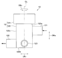
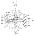
- the valve device 10 has a housing 12 that forms an outer shell.
- the valve device 10 is composed of a three-way valve having an inlet portion 121 for inflowing fluid, a first outlet portion 122 for discharging fluid, and a second outlet portion 123 for discharging fluid in the housing 12.
- the valve device 10 not only functions as a flow path switching valve, but also adjusts the flow rate ratio of the fluid flowing from the inlet portion 121 to the first outlet portion 122 and the fluid flowing from the inlet portion 121 to the second outlet portion 123. It also functions as a flow control valve.
- the valve device 10 is configured as a disc valve that opens and closes a valve by rotating a disk-shaped valve body around the axis CL of the shaft 20, which will be described later.
- the direction along the axis CL of the shaft 20 described later is defined as the axial direction DRa
- the direction orthogonal to the axial direction DRa and extending radially from the axial direction DRa is defined as the radial DRr. Etc. will be explained.
- various configurations and the like will be described with the direction around the axial center CL as the circumferential direction DRc.
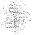
- a stator 14 As shown in FIG. 3, in the valve device 10, a stator 14, a drive unit 16, a rotating unit 18, an urging member 26, and the like are housed inside the housing 12.
- the housing 12 is a non-rotating member that does not rotate.
- the housing 12 is made of, for example, a resin material.
- the housing 12 has a bottomed tubular main body 120 extending along the axial direction DRa and a main body cover 124 that closes the opening 120a of the main body 120.
- the main body 120 has a bottom wall 120b forming the bottom surface and a side wall 120c surrounding the axis CL.
- an inlet portion 121 is formed at a position closer to the opening 120a than the bottom wall portion 120b, and a first outlet portion 122 and a second outlet portion 123 are formed at a position closer to the bottom wall portion 120b than the opening 120a. Is formed.
- an annular protrusion 120d that protrudes so as to approach the axial center CL is formed.
- the protrusion 120d is provided to arrange the stator 14 inside the main body 120.
- the protrusion 120d is provided with a pin for preventing rotation, and the pin regulates the movement of the stator 14 in the circumferential direction DRc.
- the detent of the stator 14 may be realized by means other than the detent pin.
- the inside of the main body 120 is partitioned by a stator 14 into an inlet side space 120e and an exit side space 120f.
- the entrance side space 120e is a space that communicates with the entrance portion 121 inside the housing 12.
- the outlet side space 120f is a space that communicates with the first outlet portion 122 and the second outlet portion 123 inside the housing 12.
- a plate-shaped partition 125 for partitioning the outlet side space 120f into the first outlet side space 120g and the second outlet side space 120h is set inside the main body 120.
- the partition portion 125 is provided so as to cross the outlet side space 120f along the radial direction DRr.
- the stator 14 is made of a material having a small coefficient of linear expansion and excellent wear resistance as compared with the constituent material of the housing 12.
- the stator 14 is made of a high hardness material having a hardness higher than that of the housing 12.
- the stator 14 is made of ceramic. In the stator 14, only the portion forming the opening surface 140 is formed of a material having a small coefficient of linear expansion such as ceramic and excellent wear resistance as compared with the constituent material of the housing 12. May be good.
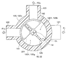
- stator 14 constitutes a flow path forming portion in which a flow path hole through which a fluid passes is formed. As shown in FIG. 4, the stator 14 is formed with a first flow path hole 141 and a second flow path hole 142 through which a fluid passes.
- the first flow path hole 141 and the second flow path hole 142 are formed at positions of the stator 14 away from the axis CL of the shaft 20 so as not to overlap with the axis CL of the shaft 20.
- the first flow path hole 141 and the second flow path hole 142 are sector-shaped (that is, fan-shaped) through holes, and the first flow path hole 141 and the second flow path hole 142 are an inlet side space 120e and an outlet. It functions as a communication passage that communicates with the side space 120f.
- the first flow path hole 141 and the second flow path hole 142 are not limited to the sector shape, and may have other shapes such as a circular shape and an elliptical shape.
- the first flow path hole 141 is provided in a portion of the stator 14 corresponding to the first outlet side space 120 g so as to communicate with the first outlet side space 120 g.
- the second flow path hole 142 is provided in a portion of the stator 14 corresponding to the second outlet side space 120h so as to communicate with the second outlet side space 120h.
- the other end side portion 20b of the shaft 20 is a portion of the shaft 20 that is opposite to the one end side portion 20a to which the rotational force is transmitted from the drive unit 16 in the axial direction DRa.
- the other end side bearing portion 144 that rotatably supports the other end side portion 20b of the shaft 20 is arranged.
- the other end side bearing portion 144 is composed of a slide bearing that receives the other end side portion 20b by the sliding surface.
- the other end side bearing portion 144 may be composed of other bearings such as ball bearings instead of the slide bearings.
- the holding portion is composed of the holding hole 143 and the bearing portion 144 on the other end side.
- the drive unit 16 is a device for outputting a rotational force.
- the drive unit 16 has a motor 161 as a drive source and a gear unit 162 as a power transmission member that transmits the output of the motor 161 to the shaft 20.
- the motor 161 is a drive source that rotates by receiving electric power.
- the motor 161 rotates according to a control signal from the valve control unit 17 electrically connected to the motor 161.
- the valve control unit 17 is a computer having a memory which is a non-transitional substantive storage medium, a processor, and the like.
- the valve control unit 17 executes a computer program stored in the memory and executes various control processes according to the computer program.
- the gear unit 162 has a plurality of gears.
- the gear unit 162 transmits the rotational operation of the motor 161 to the rotating unit 18 by meshing the plurality of gears with each other to rotate the rotating unit 18.
- the gear unit 162 transmits the rotational operation of the motor 161 to the shaft 20 of the rotating unit 18 to rotate the shaft 20 and the rotor 22 constituting the rotating unit 18.
- the gear portion 162 of the present embodiment is composed of a gear mechanism including a helical gear or a spur gear as a gear.
- the gear portion 162 is not limited to the gear mechanism described above, and may be composed of, for example, a worm gear having a worm and a worm wheel as gears.
- the rotating unit 18 rotates about the axis CL of the shaft 20 by the output of the driving unit 16 in the valve device 10.
- the rotating portion 18 has a shaft 20, a rotor 22 as a valve body, and a meson 24 that connects the rotor 22 to the shaft 20.
- one end side portion 20a is rotatably supported by one end side bearing portion 126 provided in the main body cover portion 124, and the other end side portion 20b is rotatably supported by the other end side bearing portion 144.
- the one end side bearing portion 126 is composed of a slide bearing that receives the one end side portion 20a by the sliding surface.
- the one-end side bearing portion 126 may be composed of other bearings such as ball bearings instead of the slide bearings.
- the rotor 22 is a valve body that increases or decreases the opening degree of the first flow path hole 141 and the opening degree of the second flow path hole 142 as the shaft 20 rotates.
- the opening degree of the first flow path hole 141 is the degree to which the first flow path hole 141 is opened, and is represented as 100% when the first flow path hole 141 is fully opened and 0% when the first flow path hole 141 is fully closed.
- Fully opening the first flow path hole 141 is, for example, a state in which the first flow path hole 141 is not blocked by the rotor 22 at all.
- the fully closed first flow path hole 141 is, for example, a state in which the entire first flow path hole 141 is completely closed by the rotor 22.
- the opening degree of the second flow path hole 142 is the same as the opening degree of the first flow path hole 141.
- the rotor 22 is composed of a disk-shaped member whose thickness direction is the axial direction DRa.
- the rotor 22 is arranged in the inlet side space 120e so as to face the stator 14 in the axial direction DRa.
- the rotor 22 has a sliding surface 220 that slides relative to the opening surface 140 of the stator 14.
- the sliding surface 220 is a sealing surface that seals the opening surface 140 of the stator 14.
- the rotor 22 is made of a material having a small coefficient of linear expansion and excellent wear resistance as compared with the constituent material of the housing 12.
- the rotor 22 is made of a high hardness material having a hardness higher than that of the housing 12. Specifically, the rotor 22 is made of ceramic. In the rotor 22, only the portion forming the sliding surface 220 is made of a material having a small coefficient of linear expansion such as ceramic and excellent wear resistance as compared with the constituent material of the housing 12. You may.
- the rotor 22 has a rotor hole 221 formed at a position eccentric with respect to the axial center CL of the shaft 20.
- the rotor hole 221 is a through hole penetrating in the axial direction DRa.
- the rotor hole 221 is located at a portion of the rotor 22 that overlaps the first flow path hole 141 and the second flow path hole 142 in the axial direction DRa when the rotor 22 is rotated around the axis CL of the shaft 20. It is formed.
- valve device 10 when the rotor 22 is rotated so that the rotor hole 221 overlaps the first flow path hole 141 in the axial direction DRa, the first flow path hole 141 is opened. Further, in the valve device 10, when the rotor 22 is rotated so that the rotor hole 221 overlaps the second flow path hole 142 in the axial direction DRa, the second flow path hole 142 is opened.
- the rotor 22 is configured so that the flow rate ratio of the fluid passing through the first flow path hole 141 and the fluid passing through the second flow path hole 142 can be adjusted. That is, the rotor 22 is configured so that the opening degree of the second flow path hole 142 decreases as the opening degree of the first flow path hole 141 increases.
- the meson 24 constitutes a part of the connecting structure for connecting the rotor 22 to the shaft 20.
- the meson 24 also functions as a rotation prevention mechanism for preventing the rotor 22 from rotating.
- the meson 24 connects the rotor 22 to the shaft 20 so that a gap is formed between the other end side portion 20b and the rotor 22.
- the meson 24 is provided at a position closer to the one end side portion 20a in the axial direction DRa than the rotor 22.
- the meson 24 has an intermediate tubular portion 241 that covers the outer periphery of the shaft 20 and an intermediate pin 242 that protrudes from the intermediate tubular portion 241 toward the rotor 22 along the axial direction DRa.
- the intermediate tubular portion 241 is connected to the shaft 20 by a connecting means such as press fitting, fitting, or bonding so that the intermediate tubular portion 241 can rotate integrally with the shaft 20.
- the intermediate pin 242 is a member that transmits the rotation of the shaft 20 to the rotor 22.
- the intermediate pin 242 is configured to be able to be fitted into the pin receiving portion 222 formed on the surface of the rotor 22 on the opposite side of the sliding surface 220.
- the meson 24 configured in this way is configured to prevent the rotor 22 from rotating by fitting the meson pin 242 into the pin receiving portion 222.
- the rotation prevention mechanism of the rotor 22 is not limited to the above-mentioned one, and may be realized by other means.
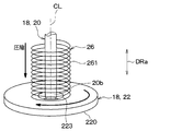
- the urging member 26 is a member that urges the rotor 22 toward the stator 14 corresponding to the flow path forming portion. As shown in FIG. 5, the urging member 26 is composed of a coil-shaped compression spring 261 that applies a compressive load to the rotor 22.
- the compression spring 261 is an elastic member that elastically deforms in the axial direction DRa of the shaft 20.
- the compression spring 261 is formed by being wound around the axis CL of the shaft 20. That is, the shaft 20 is arranged inside the compression spring 261. The compression spring 261 is arranged in a compressed state between the drive unit 16 and the rotor 22.
- the compression spring 261 is inside the housing 12 so that one end of the axial DRa is in contact with the main body cover portion 124 and the other end of the axial DRa is in contact with the rotor 22. Is located in.
- the compression spring 261 is not fixed to at least one of the rotor 22 and the main body cover portion 124 so as not to function as a torsion spring.
- the compression spring 261 employs a spring whose both ends are closed ends so that it is difficult to incline with respect to the axial center CL of the shaft 20.
- the closed-end spring has the end of the spring wire attached to the adjacent winding by changing the winding angle only for the winding at the end of the spring in order to improve the installation of the spring.
- the compression spring 261 may employ a spring having open ends at both ends.
- This contact state is a state in which the opening surface 140 of the stator 14 and the sliding surface 220 of the rotor 22 are in surface contact with each other.
- the contact point where the stator 14 and the rotor 22 are in contact between the first flow path hole 141 and the second flow path hole 142 is defined as the first contact point P1.
- FIG. 6 what is shown in FIG. 6 is a second virtual line VL1 that passes through the first contact P1 and the axial center CL of the shaft 20 and a second virtual line VL1 that is orthogonal to the first virtual line VL1 and passes through the axial center CL of the shaft 20.
- the virtual line VL2 is divided into four areas A1, A2, A3, and A4.
- the contact point where the stator 14 and the rotor 22 are in contact with each other in the third region A3 other than the first region A1 and the second region A2 adjacent to each other via the first contact P1 is the second contact P2.
- the contact point where the stator 14 and the rotor 22 are in contact with each other in the fourth region A4 is the third contact point P3.
- the first contact P1, the second contact P2, and the third contact P3 in which the stator 14 and the rotor 22 are in contact with each other are not limited to those shown in FIG.
- the first contact P1, the second contact P2, and the third contact P3 may be defined based on, for example, the load acting on the stator 14 from the rotor 22 by the urging member 26.
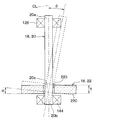
- FIG. 7 is an enlarged partially enlarged view of the VII portion of FIG.
- the connecting structure between the shaft 20 and the rotor 22 includes a fitting structure 28 in which a part of the shaft 20 is fitted into the fitting hole 223 provided in the rotor 22.
- the fitting structure 28 has a fitting structure in which a part of the shaft 20 is gap-fitted with respect to the fitting hole 223 of the rotor 22.
- the shaft 20 of the present embodiment constitutes a fitting portion 20c in which a part of the other end side portion 20b is fitted into the fitting hole 223 provided in the rotor 22.
- the fitting portion 20c is a portion of the other end side portion 20b that overlaps with the rotor 22 in the radial DRr.
- the fitting hole 223 has a size such that a gap is formed between the fitting hole 223 and the shaft 20 so that the shaft 20 can be tilted in a state where a part of the shaft 20 is fitted. That is, the diameter ⁇ g of the fitting hole 223 is larger than the diameter ⁇ s of the fitting portion 20c of the shaft 20 (that is, ⁇ g> ⁇ s).
- the gap between the fitting hole 223 and the fitting portion 20c is larger than the gap between the other end side bearing portion 144 forming the holding portion of the shaft 20 and the fitting portion 20c.
- the fitting dimension difference ⁇ a which is the difference between the diameter ⁇ g of the fitting hole 223 and the diameter ⁇ g of the fitting portion 20c, is the inner diameter ⁇ b of the bearing portion 144 on the other end side and the diameter ⁇ g of the fitting portion 20c. It is larger than the shaft dimensional difference ⁇ b, which is the difference between the two (that is, ⁇ a> ⁇ b).
- the diameter ⁇ g described above cannot be specified. Therefore, for example, when the fitting hole 223 is not circular, the diameter ⁇ g of the fitting hole 223 is set to the diameter of a circle having the same cross-sectional area as the fitting hole 223 (that is, the equivalent diameter), and the above-mentioned magnitude relationship is set. You may be. This also applies to the fitting portion 20c and the bearing portion 144 on the other end side.
- the shaft 20 and the rotor 22 may change from the design target posture shown by the solid line to the tilted posture shown by the broken line due to some factor.
- Factors that cause the shaft 20 and the rotor 22 to tilt include, for example, dimensional variation in the axial direction DRa of the shaft 20, and a structure in which both ends of the shaft 20 are held by separate members. In such a structure, if the assembly accuracy of the main body cover portion 124 and the main body portion 120 is not sufficient, the relative positions of the one end side bearing portion 126 and the other end side bearing portion 144 are displaced in the radial direction DRr, and the shaft 20 is displaced. It tilts.
- valve device 10 of the present embodiment is fitted into the fitting hole 223 of the rotor 22 with a fitting structure in which a part of the shaft 20 is gap-fitted. According to this, it is not necessary to increase the pressing load by the urging member 26, and the increase in the load torque can be suppressed.
- the fitting hole it is desirable that the gap G between the 223 and the fitting portion 20c satisfies the following mathematical formula F1.
- the gap G between the fitting hole 223 and the fitting portion 20c satisfies the following mathematical formula F1
- the opening surface 140 of the stator 14 and the rotor 22 It is possible to make surface contact with the sliding surface 220 of the above.
- the gap G between the fitting hole 223 and the fitting portion 20c is an allowable amount of deviation in the radial DRr between the rotation center of the one end side portion 20a of the shaft 20 and the rotation center of the other end side portion 20b. It may be set to be larger than the deviation amount. This also ensures that the rotor 22 and the stator 14 are in close contact with each other within the design range.
- the fluid flows from the inlet portion 121 into the inlet side space 120e as shown by the arrow Fi.
- the fluid flows from the inlet side space 120e to the first outlet side space 120g via the first flow path hole 141.
- the fluid that has flowed into the first outlet side space 120 g flows out from the first outlet side space 120 g via the first outlet portion 122 to the outside of the valve device 10 as shown by an arrow F1o.
- the flow rate of the fluid passing through the first flow path hole 141 is determined according to the opening degree of the first flow path hole 141. That is, the flow rate of the fluid flowing from the inlet portion 121 to the first outlet portion 122 through the first flow path hole 141 increases as the opening degree of the first flow path hole 141 increases.
- the second flow path hole 142 when the second flow path hole 142 is open, the fluid flows from the inlet side space 120e into the second outlet side space 120h via the second flow path hole 142.
- the fluid that has flowed into the second outlet side space 120h flows out from the second outlet side space 120h to the outside of the valve device 10 via the second outlet portion 123 as shown by the arrow F2o.
- the flow rate of the fluid passing through the second flow path hole 142 is determined according to the opening degree of the second flow path hole 142. That is, the flow rate of the fluid flowing from the inlet portion 121 to the second outlet portion 123 through the second flow path hole 142 increases as the opening degree of the second flow path hole 142 increases.
- the valve device 10 of the present embodiment described above has a connecting structure in which the shaft 20 is tiltably connected to the rotor 22. According to this, even if the shaft 20 is tilted for some reason, it is possible to secure the adhesion between the rotor 22 and the stator 14 constituting the flow path forming portion.
- the posture of the rotor 22 is defined by the pressure of the fluid.
- the posture of the rotor 22 is not determined, and it becomes insufficient to secure the adhesion between the rotor 22 and the stator 14 constituting the flow path forming portion.
- valve device 10 of the present embodiment has a peculiar action and effect that fluid leakage due to a change in the posture of the shaft 20 can be suppressed by the organic coupling between the above-mentioned connecting structure and the urging member 26. Play.
- the connecting structure between the shaft 20 and the rotor 22 includes a fitting structure 28 in which the fitting portion 20c of the shaft 20 is fitted into the fitting hole 223 provided in the rotor 22.
- the fitting hole 223 has a size such that a gap is formed between the fitting hole 223 and the shaft 20 so that the shaft 20 can be tilted while the fitting portion 20c is fitted.
- the fitting structure 28 in which a gap is formed between the fitting hole 223 and the fitting portion 20c the contact between the fitting hole 223 and the fitting portion 20c is suppressed, so that the sliding in the connecting structure It is possible to suppress dynamic loss and ensure wear resistance. That is, the fitting structure 28 can suppress sliding loss and ensure wear resistance as compared with a connecting structure in which members slide with each other like a joint.
- the gap between the fitting hole 223 and the fitting portion 20c is larger than the gap between the other end side bearing portion 144 forming the holding portion of the shaft 20 and the fitting portion 20c.
- the urging member 26 is composed of a compression spring 261 which is an elastic member elastically deformed in the axial direction DRa of the shaft 20. According to this, a sufficient load for pressing the sliding surface 220 of the rotor 22 toward the opening surface 140 of the stator 14 can be sufficiently secured, so that the contact state between the sliding surface 220 and the opening surface 140 is maintained. It will be easier.
- the shaft 20 is arranged inside the compression spring 261. According to this, since the load of the compression spring 261 on the rotor 22 is suppressed from being biased in the circumferential direction DRc of the shaft 20, the contact state between the sliding surface 220 and the opening surface 140 is easily maintained.
- a coil-shaped compression spring 261 is used as the urging member 26, but the urging member 26 is not limited to the compression spring 261.
- the urging member 26 may be composed of a cylindrical elastic body 262 that elastically deforms in the axial direction DRa of the shaft 20.
- the elastic body 262 is made of, for example, a stretchable rubber material.
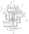
- the shaft 20 is provided with a flange portion 20d protruding in the radial DRr of the shaft 20 at a position closer to one end side portion 20a than the rotor 22.
- the flange portion 20d is formed in a disk shape and is provided with respect to the shaft 20 so as to rotate integrally with the shaft 20.
- the outer diameter of the flange portion 20d is larger than the outer diameter of the compression spring 261.
- the compression spring 261 is arranged in a compressed state between the rotor 22 and the flange portion 20d so as to rotate together with the rotor 22. Specifically, the compression spring 261 is inside the housing 12 so that one end of the axial DRa is in contact with the flange 20d and the other end of the axial DRa is in contact with the rotor 22. Have been placed. The compression spring 261 is not fixed to at least one of the rotor 22 and the main body cover portion 124 so as not to function as a torsion spring.
- valve device 10 of the present embodiment can obtain the same or the same effect as that of the first embodiment.
- the compression spring 261 is arranged in a compressed state between the rotor 22 and the flange portion 20d. According to this, since the compression spring 261 rotates integrally with the rotor 22 and the shaft 20, it is possible to suppress the sliding loss due to the sliding of the compression spring 261 and to secure the wear resistance. Further, since the compression spring 261 does not function as a torsion spring, it is possible to prevent an unnecessary force from acting on the rotor 22 in the circumferential direction around the axial center CL of the shaft 20.
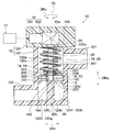
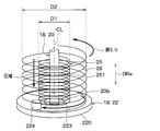
- the valve device 10 includes a coiled torsion spring 29 that urges the rotor 22 on one side of the circumferential DRc around the axial CL of the shaft 20.
- the torsion spring 29 is arranged between the drive unit 16 and the rotor 22.
- the torsion spring 29 is formed by being wound around the axial center CL of the shaft 20.
- the coil diameter D2 of the torsion spring 29 is larger than the coil diameter D1 of the compression spring 261.
- a compression spring 261 is arranged inside the torsion spring 29.
- the torsion spring 29 is fixed to the rotor 22 and the main body cover portion 124, respectively.
- one end side of the axial DRa is connected to the main body cover portion 124 so as not to be relatively rotatable, and the other end side of the axial direction DRa is connected to the rotor 22 so as not to be relatively rotatable.
- Various methods of connecting the torsion spring 29 to the rotor 22 are conceivable.
- the end of the torsion spring 29 is connected to the rotor 22 by being locked to a fixing pin 224 fixed to the rotor 22. To.
- the smaller the coil diameter D the larger the spring constant of the coil spring.
- the spring constant is large, the load acting on the rotor 22 fluctuates greatly. Such load fluctuations can be a factor in deteriorating the adhesion between the rotor 22 and the stator 14.
- valve device 10 of the present embodiment can obtain the same or the same effect as that of the first embodiment.
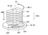
- the urging member 26 not only urges the rotor 22 toward the stator 14, but also urges the rotor 22 to one side of the circumferential DRc. It is composed of elastic members that are connected together. Specifically, the urging member 26 is composed of a compression spring 261 configured to also function as a torsion spring.
- the compression spring 261 of this embodiment is fixed to each of the rotor 22 and the main body cover portion 124.
- one end side of the axial DRa is connected to the main body cover portion 124 so as not to be relatively rotatable, and the other end side of the axial direction DRa is connected to the rotor 22 so as not to be relatively rotatable.
- Various methods of connecting the compression spring 261 to the rotor 22 are conceivable.
- the end of the compression spring 261 is connected to the rotor 22 by being locked to a fixing pin 225 fixed to the rotor 22. To.
- the compression spring 261 is used in a state of being twisted in the circumferential direction DRc to cause elastic deformation.
- the compression spring 261 generates an urging force that urges the rotor 22 to one side of the circumferential DRc due to its elastic deformation.
- valve device 10 of the present embodiment can obtain the same or the same effect as that of the first embodiment.
- the elastic member has a function as a torsion spring in addition to a function as a compression spring 261. Therefore, the position of the rotor 22 and the shaft 20 are displaced in the circumferential direction DRc of the shaft 20 while maintaining the posture of the rotor 22 in contact with the stator 14 without increasing the number of parts of the valve device 10. Can be suppressed.
- a seal member 30 is arranged between the stator 14 and the housing 12.
- the seal member 30 is interposed between the stator 14 and the protrusion 120d of the housing 12.
- the seal member 30 is configured to be elastically deformable in the axial direction DRa. As shown in FIG. 18, the seal member 30 is composed of a disk-shaped member having the axial direction DRa as the thickness direction. The seal member 30 has an outer diameter equivalent to that of the stator 14 so as to overlap the stator 14 in the axial direction DRa. Further, the thickness of the seal member 30 is smaller than the thickness of the stator 14.
- the seal member 30 is formed with a first through hole 30a through which a fluid passes through a portion facing the first flow path hole 141. Further, the seal member 30 is formed with a second through hole 30b through which a fluid passes through a portion facing the second flow path hole 142.
- valve device 10 of the present embodiment can obtain the same or the same effect as that of the first embodiment.
- the seal member 30 is arranged between the stator 14 and the housing 12. According to this, the sealing property between the stator 14 and the housing 12 can be ensured by the sealing member 30. Further, for example, if the pressure acting on the rotor 22 varies in the circumferential direction DRc, the rotor 22 may be in an inclined posture, but even in this case, the stator 14 is rotated by the deformation of the seal member 30. It is possible to follow the child 22 and tilt it. As described above, according to the configuration in which the seal member 30 is interposed between the stator 14 and the housing 12, the adhesion between the stator 14 and the rotor 22 can be ensured, and fluid leakage in the valve device 10 can be ensured. Can be sufficiently suppressed.
- a universal joint 32 is adopted as the connecting structure between the shaft 20 and the rotor 22.
- the universal joint 32 is a joint capable of changing the joining angle. Specifically, the universal joint 32 connects the shaft 20 and the rotor 22 so that the angle formed by the sliding surface 220 of the rotor 22 and the axial center CL of the shaft 20 can be changed.
- the universal joint 32 is composed of a ball joint 321.
- the ball joint 321 is composed of a ball stud 20e provided on the other end side portion 20b of the shaft 20 and a socket 226 provided on the surface of the rotor 22.
- the ball stud 20e is made of a sphere having a spherical surface.
- the socket 226 has an inner shape corresponding to the spherical surface of the ball stud 20e so as to be in contact with the spherical surface of the ball stud 20e.
- the rotor 22 can rotate together with the shaft 20 due to the frictional force at the time of contact between the ball stud 20e and the socket 226.
- valve device 10 of the present embodiment can obtain the same or the same effect as that of the first embodiment.
- the ball joint 321 of the sixth embodiment described above is exemplified in that the ball stud 20e is provided on the other end side portion 20b of the shaft 20 and the socket 226 provided on the surface of the rotor 22 is provided. Not limited to this.
- the ball joint 321 may be composed of, for example, a socket provided on the other end side portion 20b of the shaft 20 and a ball stud provided on the rotor 22.
- the universal joint 32 of the present embodiment is composed of a universal receiving portion 227 provided on the rotor 22.
- the universal receiving portion 227 is a through hole that penetrates the rotor 22 in the thickness direction.
- the free receiving portion 227 has an arcuate surface 227a having a substantially semicircular cross section that protrudes so as to approach the axial direction DRa.
- the other end side portion 20b of the shaft 20 is supported by the free receiving portion 227 so as to be tiltable, mainly by contacting with the vicinity of the apex 227b of the arcuate surface 227a.
- the rotor 22 can rotate together with the shaft 20 due to the frictional force at the time of contact between the universal receiving portion 227 and the shaft 20.
- valve device 10 of the present embodiment can obtain the same or the same effect as that of the first embodiment.
- the shaft 20 can be tiltably supported by providing the universal receiving portion 227 with respect to the rotor 22.
- the connecting structure of the shaft 20 and the rotor 22 can be realized by a simple structure.
- the temperature control device 1 is mounted on an electric vehicle that obtains driving force for traveling from an electric motor.
- the temperature adjusting device 1 is a device that adjusts the temperature of the blown air into the vehicle interior, which is the space to be air-conditioned, and also adjusts the temperature of a plurality of in-vehicle devices including the battery BT in the electric vehicle.
- the temperature adjusting device 1 can be interpreted as an air conditioner having a temperature adjusting function of an in-vehicle device.
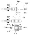
- the temperature control device 1 includes a refrigeration cycle device 200, a first fluid circulation circuit 300, a second fluid circulation circuit 400, an indoor air conditioning unit 500, a control device 600, and the like.
- the refrigeration cycle apparatus 200 constitutes a vapor compression type refrigeration cycle.
- the refrigeration cycle device 200 includes a compressor 201, a radiator 202, a first expansion valve 204, a second expansion valve 205, a chiller 206, an indoor evaporator 207, an evaporation pressure adjusting valve 208, and the like.
- the refrigeration cycle device 200 can switch the circuit configuration of the refrigerant circuit according to various operation modes described later.
- the refrigeration cycle device 200 uses an HFO-based refrigerant (for example, R1234yf) as the refrigerant.
- the refrigeration cycle device 200 constitutes a subcritical refrigeration cycle in which the maximum value of the refrigerant pressure does not exceed the critical pressure of the refrigerant.
- Refrigerant oil for example, PAG oil
- a part of the refrigerating machine oil circulates together with the refrigerant in the refrigerant circuit of the refrigerating cycle device 200.
- the compressor 201 is a device that compresses and discharges the sucked refrigerant.
- the compressor 201 is arranged in the drive system accommodation chamber on the front side of the vehicle.
- the drive system accommodation room is a space in which an electric motor or the like, which is a drive source for traveling, is arranged.
- the drive train containment chamber and the passenger compartment are separated by a fire wall.
- the refrigerant inlet side of the radiator 202 is connected to the refrigerant discharge side.
- the radiator 202 is a heat exchanger that dissipates the refrigerant by exchanging heat between the refrigerant discharged from the compressor 201 and the high-temperature heat medium circulating in the first fluid circulation circuit 300.
- the radiator 202 also functions as a heating heat exchanger that heats the high-temperature heat medium.
- the refrigeration cycle device 200 employs a so-called subcool type heat exchanger as the radiator 202. That is, the radiator 202 is provided with a condensing unit 202a, a receiver unit 202b, and a supercooling unit 202c.
- the condensing unit 202a is a heat exchange unit for condensing that condenses the high-pressure refrigerant by exchanging heat between the refrigerant discharged from the compressor 201 and the high-temperature heat medium.
- the receiver unit 202b is a liquid receiving unit that separates the gas-liquid of the refrigerant flowing out from the condensing unit 202a and stores the separated liquid-phase refrigerant.
- the supercooling unit 202c is a heat exchange unit for supercooling that supercools the liquid phase refrigerant by exchanging heat between the liquid phase refrigerant flowing out from the receiver unit 202b and the high temperature heat medium.
- the refrigerant branch portion 203 is connected to the refrigerant outlet side of the radiator 202.
- the refrigerant branching portion 203 branches the flow of the refrigerant flowing out of the radiator 202.
- the refrigerant branching portion 203 is a three-way joint having three inflow ports communicating with each other. In the refrigerant branching portion 203, one of the three inflow outlets is used as an inflow port, and the remaining two are used as an outflow port.
- the refrigerant inlet side of the chiller 206 is connected to one outlet of the refrigerant branch 203 via the first expansion valve 204.
- the refrigerant inlet side of the indoor evaporator 207 is connected to the other outlet of the refrigerant branch 203 via the second expansion valve 205.
- the first expansion valve 204 is a pressure reducing unit that reduces the pressure of the refrigerant flowing out from one outlet of the refrigerant branching unit 203.
- the first expansion valve 204 is an electric variable throttle mechanism having a valve body that changes the throttle opening degree and an electric actuator (for example, a stepping motor) that displaces the valve body.
- the operation of the first expansion valve 204 is controlled by a control pulse output from the control device 600.
- the second expansion valve 205 is a pressure reducing unit that reduces the pressure of the refrigerant flowing out from the other outlet of the refrigerant branching unit 203.
- the basic configuration of the second expansion valve 205 is the same as that of the first expansion valve 204.
- the first expansion valve 204 and the second expansion valve 205 have a fully open function that functions as a mere refrigerant passage without exerting a refrigerant depressurizing action and a flow rate adjusting action by fully opening the valve opening. Further, the first expansion valve 204 and the second expansion valve 205 have a fully closing function of closing the refrigerant passage by fully closing the valve opening degree.
- the first expansion valve 204 and the second expansion valve 205 can switch the refrigerant circuits in various operation modes by the fully open function and the fully closed function. Therefore, the first expansion valve 204 and the second expansion valve 205 also have a function as a refrigerant circuit switching unit for switching the circuit configuration of the refrigeration cycle device 200.
- the refrigerant inlet side of the chiller 206 is connected to the refrigerant outlet side of the first expansion valve 204.
- the chiller 206 is a heat exchanger that exchanges heat between the low-pressure refrigerant decompressed by the first expansion valve 204 and the low-temperature heat medium that circulates in the second fluid circulation circuit 400.
- the chiller 206 is an evaporation unit that cools a low-temperature heat medium by evaporating a low-pressure refrigerant to exert an endothermic action.
- the chiller 206 in the second fluid circulation circuit 400 is a cooling device that cools the low temperature heat medium.
- One inflow port side of the refrigerant merging portion 209 is connected to the refrigerant outlet side of the chiller 206.
- the refrigerant inlet side of the evaporation pressure adjusting valve 208 is connected to the refrigerant outlet side of the indoor evaporator 207.
- the evaporation pressure adjusting valve 208 is an evaporation pressure adjusting unit that maintains the refrigerant evaporation pressure in the indoor evaporator 207 to be equal to or higher than a predetermined reference pressure.
- the refrigerant merging section 209 joins the flow of the refrigerant flowing out of the chiller 206 and the flow of the refrigerant flowing out of the evaporation pressure adjusting valve 208.
- the refrigerant merging portion 209 is a three-way joint similar to the refrigerant branching portion 203. In the refrigerant merging section 209, two of the three inflow ports are used as inflow ports, and the remaining one is used as the outflow port.
- the refrigerant suction side of the compressor 201 is connected to the outlet of the refrigerant merging portion 209.
- the first fluid circulation circuit 300 is a fluid circulation circuit in which a high-temperature heat medium that is a fluid circulates.
- a high-temperature heat medium that is a fluid circulates.
- an ethylene glycol aqueous solution is used as the high-temperature heat medium.
- a high temperature side pump 301, a radiator 202, a high temperature side radiator 303, a heater core 304, a high temperature side switching valve 310, and the like are arranged.
- the inlet side of the heat medium passage 302 of the radiator 202 is connected to the discharge port of the high temperature side pump 301.
- the high temperature side pump 301 pumps the high temperature heat medium to the heat medium passage 302 of the radiator 202.
- the high temperature side pump 301 is an electric pump whose rotation speed (that is, pumping capacity) is controlled by a control voltage output from the control device 600.
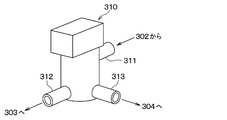
- the inlet portion 311 of the high temperature side switching valve 310 is connected to the downstream side of the electric heater 306.
- the high temperature side switching valve 310 adjusts the flow rate ratio of the high temperature heat medium flowing into the high temperature side radiator 303 and the high temperature heat medium flowing into the heater core 304.
- the high temperature side switching valve 310 constitutes the valve device of the present disclosure.
- the high temperature side switching valve 310 has the same configuration as the valve device 10 described in the first embodiment.
- the first outlet portion 312 is connected to the fluid inlet side of the high temperature side radiator 303, and causes the high temperature heat medium to flow out to the high temperature side radiator 303.
- the first outlet portion 312 corresponds to the first outlet portion 122 in the valve device 10 of the first embodiment.
- the inlet portion 311 is connected to the fluid outlet side of the high temperature side radiator 303 and the fluid outlet side of the heater core 304, and the high temperature heat medium flows in from the high temperature side radiator 303 and the heater core 304.
- the inlet portion 311 corresponds to the inlet portion 121 in the valve device 10 of the first embodiment.
- the high temperature side switching valve 310 has a configuration in which the flow rate ratio of the high temperature heat medium passing through the high temperature side radiator 303 and the high temperature heat medium passing through the heater core 304 is adjusted by rotationally displacing the rotor 22. Specifically, the high-temperature side switching valve 310 increases or decreases the opening degree of the first flow path hole 141 and the opening degree of the second flow path hole 142 by the rotor 22, so that the high-temperature heat passes through the high-temperature side radiator 303. The flow rate ratio of the medium and the high temperature heat medium passing through the heater core 304 is adjusted.
- the high-temperature side radiator 303 is an outdoor heat exchanger that exchanges heat between the high-temperature heat medium heated by the radiator 202 and the like and the air outside the vehicle interior (that is, the outside air OA) blown from an outside air fan (not shown). Is.
- the high temperature side radiator 303 is arranged on the front side of the drive system accommodation chamber. When the vehicle is running, the high temperature side radiator 303 can be exposed to the running wind (that is, the outside air OA) that has flowed into the drive system accommodation chamber via the grill.
- One inflow port side of the high temperature side merging portion 307 is connected to the fluid outlet side of the high temperature side radiator 303.
- the heater core 304 is an indoor heat exchanger that heats the blown air W by exchanging heat between the high-temperature heat medium heated by the radiator 202 or the like and the blown air W blown into the room.
- the heater core 304 is arranged in the casing 501 of the indoor air conditioning unit 500.
- the blown air W is heated by using the heat absorbed by the refrigerant in the chiller 206 as a heating source.
- the other inlet side of the high temperature side merging portion 307 is connected to the fluid outlet side of the heater core 304.
- the high temperature side reserve tank 308 is a storage unit for the high temperature heat medium that stores the high temperature heat medium that is surplus in the first fluid circulation circuit 300.
- the high temperature side reserve tank 308 has a heat medium supply port for replenishing the high temperature heat medium when the amount of the high temperature heat medium circulating in the first fluid circulation circuit 300 is insufficient.
- the second fluid circulation circuit 400 is a fluid circulation circuit in which a low-temperature heat medium that is a fluid circulates.
- a heat medium of the same type as the high temperature heat medium is used as the low temperature heat medium.
- the low temperature side pump 401 In the second fluid circulation circuit 400, the low temperature side pump 401, the heat medium passage 402 of the chiller 206, the low temperature side radiator 403, the flow path switching valve 70, the cooling water passage 405 of the battery BT, the cooling water passage 406 of the in-vehicle device CE, etc. Is placed.
- a low temperature heat medium is connected to the fluid outlet side of the low temperature side pump 401 to the inlet side of the heat medium passage 402 of the chiller 206.
- the low temperature side pump 401 is a pumping unit that pumps the low temperature heat medium to the heat medium passage 402 of the chiller 206.
- the basic configuration of the low temperature side pump 401 is the same as that of the high temperature side pump 301.
- the first inlet portion 700A side of the flow path switching valve 70 is connected to the fluid outlet side of the heat medium passage 402 of the chiller 206.
- the flow path switching valve 70 is a circuit switching unit that switches the circuit configuration of the second fluid circulation circuit 400.
- the flow path switching valve 70 is provided with a plurality of inlet portions and a plurality of outlet portions.
- a cooling water passage 405 of the battery BT, a low temperature radiator 403, and the like are connected to these inlets and outlets. The detailed configuration of the flow path switching valve 70 will be described later.
- the battery BT supplies electric power to the electric in-vehicle device CE such as an electric motor.
- the battery BT is an assembled battery formed by electrically connecting a plurality of battery cells in series or in parallel.
- the battery cell is composed of a rechargeable secondary battery (for example, a lithium ion battery).
- the battery BT is a battery BT in which a plurality of battery cells are stacked and arranged so as to have a substantially rectangular parallelepiped shape and housed in a special case.
- the temperature of the battery BT is maintained within an appropriate temperature range (for example, 15 ° C. or higher and 55 ° C. or lower) so that the charge / discharge capacity of the battery BT can be fully utilized.
- the passage configuration of the cooling water passage 405 of the battery BT is a passage configuration in which a plurality of passages are connected in parallel inside the dedicated case.
- the cooling water passage 405 of the battery BT is formed so as to be able to absorb heat evenly from the entire area of the battery BT.
- the cooling water passage 405 is formed so that the heat of all the battery cells can be uniformly absorbed and all the battery cells can be cooled.
- One inflow port side of the low temperature side confluence 407 is connected to the heat medium outlet of the low temperature side radiator 403 via the low temperature side reserve tank 408.
- the low temperature side reserve tank 408 is a storage unit for the low temperature heat medium that stores the low temperature heat medium that is surplus in the second fluid circulation circuit 400.
- the basic configuration of the low temperature side reserve tank 408 is the same as that of the high temperature side reserve tank 308.
- the low temperature side merging portion 407 is a three-way joint similar to the high temperature side merging portion 307 and the like.
- the second fluid circulation circuit 400 is connected to the equipment cooling passage 410 in which the cooling water passage 406 of the in-vehicle equipment CE is arranged.
- the equipment cooling passage 410 is connected so as to return the low-temperature heat medium on the downstream side of the low-temperature side reserve tank 408 and on the upstream side of the low-temperature side confluence portion 407 to the inlet side of the low-temperature side radiator 403 again. There is.
- the equipment pump 411 is arranged in the equipment cooling passage 410.
- the equipment pump 411 pumps the low temperature heat medium to the cooling water passage 406 of the vehicle-mounted equipment CE.
- the basic configuration of the equipment pump 411 is the same as that of the low temperature side pump 401.
- the in-vehicle device CE is a heat generating device that generates heat when operated.
- the in-vehicle device CE is an electric motor, an inverter, a control device for an advanced driving system, and the like.
- An electric motor is an in-vehicle device that outputs a driving force for traveling.
- An inverter is an in-vehicle device that supplies electric power to an electric motor.
- the control device for advanced driver assistance systems is a control device for so-called ADAS.
- ADAS is an abbreviation for Advanced Driver Assistance System.
- a cooling water passage 406 for circulating a low temperature heat medium is formed inside the housing portion or the case forming the outer shell of the in-vehicle device CE.
- the cooling water passage 406 is an endothermic heat medium passage for absorbing the heat of the vehicle-mounted device CE (that is, the waste heat of the vehicle-mounted device CE) into the low-temperature heat medium.
- the cooling water passage 406 constitutes a temperature control unit that adjusts the temperature of the in-vehicle device CE, which is a heat generating device.
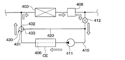
- a detour passage 420 for equipment is connected to the second fluid circulation circuit 400.
- the device bypass passage 420 is a heat medium passage that bypasses the low-temperature heat medium flowing out of the cooling water passage 406 of the in-vehicle device CE and returns it to the fluid inlet side of the device pump 411 by bypassing the low-temperature side radiator 403 and the like.
- the device bypass passage 420 constitutes a bypass portion for passing a low-temperature heat medium by bypassing the low-temperature side radiator 403, which is an outdoor heat exchanger.
- the equipment flow rate adjusting valve 412 is arranged on the upstream side of the connection portion with the equipment detour passage 420.
- the equipment flow rate adjusting valve 412 is an electric flow rate adjusting valve having a valve body that changes the passage cross-sectional area of the equipment cooling passage 410 and an electric actuator (for example, a stepping motor) that displaces the valve body.
- the operation of the flow control valve 412 for equipment is controlled by a control pulse output from the control device 600.
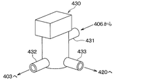
- a low temperature side switching valve 430 is arranged at the connection portion between the equipment cooling passage 410 and the equipment detour passage 420.
- the low temperature side switching valve 430 adjusts the flow rate ratio between the low temperature heat medium flowing into the low temperature side radiator 403 and the low temperature heat medium flowing into the equipment bypass passage 420.
- the low temperature side switching valve 430 constitutes the valve device of the present disclosure in the same manner as the high temperature side switching valve 310.
- the low temperature side switching valve 430 has the same configuration as the valve device 10 described in the first embodiment.
- the first outlet portion 432 is connected to the fluid inlet side of the low temperature side radiator 403, and causes the low temperature heat medium to flow out to the low temperature side radiator 403.
- the first outlet portion 432 corresponds to the first outlet portion 122 in the valve device 10 of the first embodiment.
- the inlet portion 431 is connected to the fluid outlet side of the cooling water passage 406 of the in-vehicle device CE, which is a temperature control portion, and the fluid that has passed through the cooling water passage 406 flows in.
- the inlet 431 corresponds to the inlet 121 in the valve device 10 of the first embodiment.
- the low temperature side switching valve 430 has a configuration in which the flow rate ratio of the low temperature heat medium passing through the low temperature side radiator 403 and the low temperature heat medium passing through the device bypass passage 420 is adjusted by rotationally displacing the rotor 22. There is. Specifically, the low temperature side switching valve 430 increases or decreases the opening degree of the first flow path hole 141 and the opening degree of the second flow path hole 142 by the rotor 22, so that the low temperature heat passes through the low temperature side radiator 403. The flow rate ratio of the medium and the low temperature heat medium passing through the device bypass passage 420 is adjusted.
- the operation of the low temperature side switching valve 430 is controlled by the control pulse output from the control device 600.
- the control device 600 also has a function as the valve control unit 17 described in the first embodiment.
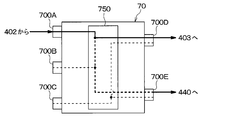
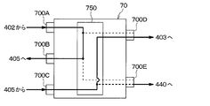
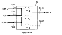
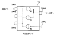
- a short-circuit heat medium passage that guides the low-temperature heat medium flowing out from the third outlet portion 700E of the flow path switching valve 70 to the other inflow port of the low-temperature side merging portion 407. 440 is connected.
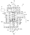
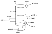
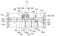
- the flow path switching valve 70 has a resin main body portion 701 formed in a bottomed tubular shape.
- the main body 701 is a housing having a plurality of inlet portions for flowing the low temperature heat medium into the inside and a plurality of outlet portions for allowing the low temperature heat medium to flow out from the inside.
- the main body portion 701 of the present embodiment has two inlet portions and three outlet portions. Therefore, the flow path switching valve 70 is a five-way valve having five entrances and exits.
- the flow path switching valve 70 is provided with a first inlet portion 700A and a second inlet portion 700C.
- the first inlet portion 700A is a low-temperature heat medium pumped from the low-temperature side pump 401, and is an inlet portion through which the low-temperature heat medium that has passed through the heat medium passage 402 of the chiller 206 flows in.
- the second inlet portion 700C is an inlet portion through which the low-temperature heat medium flowing out from the cooling water passage 405 of the battery BT flows in.
- the flow path switching valve 70 is provided with a first outlet portion 700B, a second outlet portion 700D, and a third outlet portion 700E.
- the first outlet portion 700B is an outlet portion that allows the low temperature heat medium to flow out to the fluid inlet side of the cooling water passage 405 of the battery BT.
- the second outlet portion 700D is an outlet portion that allows the low temperature heat medium to flow out to the fluid inlet side of the low temperature side radiator 403.
- the third outlet portion 700E is an outlet portion that allows the low temperature heat medium to flow out to the fluid inlet side of the heat medium passage 402 of the chiller 206 (that is, to the short circuit heat medium passage 440).
- the cooling water passage 405 of the battery BT is arranged in the heat medium passage from the first outlet portion 700B to the second inlet portion 700C.
- the cooling water passage 405 of the battery BT is arranged in the heat medium passage from the first outlet portion 700B to the second inlet portion 700C.
- the second inlet portion 700C serves as an inlet portion for allowing the low-temperature heat medium that has flowed out from the first outlet portion 700B to the outside of the main body portion 701 to flow into the inside again.
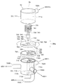
- the main body 701 of the flow path switching valve 70 is divided into a first main body 711 and a second main body 712. Both the first main body portion 711 and the second main body portion 712 are formed in a cylindrical shape and are arranged coaxially. One end side of the first main body portion 711 in the axial direction DRa is closed by the lid portion, and the other end side is open. The other end side of the second main body portion 712 in the axial direction DRa is closed by the bottom portion, and one end side is open.
- a stator 720 is arranged inside the main body 701.
- the stator 720 is arranged near the connection portion between the first main body portion 711 and the second main body portion 712.
- a plurality of spaces are formed inside the main body 701 by the stator 720.
- the first entrance side space 711a is formed inside the first main body portion 711.
- the first entrance side space 711a is a substantially columnar space communicating with the first entrance portion 700A.
- a first outlet side space 712b, a second entrance side space 712c, a second exit side space 712d, and a third exit side space 712e are formed inside the second main body portion 712.
- a plurality of partition plates 713 extending radially from the axis CL of the shaft 740 are arranged inside the second main body portion 712.
- the partition plate 713 divides the internal space of the second main body portion 712 into a plurality of spaces in the circumferential direction DRc.
- the first exit side space 712b is a space communicating with the first exit portion 700B.
- the second entrance side space 712c is a space communicating with the second entrance portion 700C.
- the second exit side space 712d is a space communicating with the second exit portion 700D.
- the third exit side space 712e is a space communicating with the third exit portion 700E.
- the first exit-side space 712b, the second inlet-side space 712c, the second exit-side space 712d, and the third exit-side space 712e are all formed in a sector-like (that is, fan-like) cross section in the axial direction DRa. It is a columnar space that extends.
- the first exit side space 712b, the third exit side space 712e, the second entrance side space 712c, and the second exit side space 712d are in this order when viewed from the first main body portion 711 side toward the axial direction DRa. It is arranged clockwise. That is, the second entrance side space 712c is arranged so as to be adjacent to both the second exit side space 712d and the third exit side space 712e in the circumferential direction DRc.
- the stator 720 is a member corresponding to the stator 14 of the valve device 10 of the first embodiment.
- the constituent materials and the like of the stator 720 are the same as those of the stator 14 of the first embodiment.
- the stator 720 is composed of a disk-shaped member whose thickness direction is the axial direction DRa.
- the stator 720 has an opening surface 721 as a surface on which the rotor 750, which will be described later, slides.
- the opening surface 721 is a sealing surface corresponding to the sliding surface 751 of the rotor 750, which will be described later.
- the stator 720 constitutes a flow path forming portion in which a flow path hole through which a fluid passes is formed.
- the stator 720 is formed with a first flow path hole 722, a second flow path hole 723, a third flow path hole 724, and a fourth flow path hole 725 through which the fluid passes.
- the first flow path hole 722 is provided in a portion of the stator 720 corresponding to the first outlet side space 712b so as to communicate with the first outlet side space 712b.
- the second flow path hole 723 is provided in a portion of the stator 720 corresponding to the second inlet side space 712c so as to communicate with the second inlet side space 712c.
- the third flow path hole 724 is provided in a portion of the stator 720 corresponding to the second outlet side space 712d so as to communicate with the second outlet side space 712d.
- the fourth flow path hole 725 is provided in a portion of the stator 720 corresponding to the third outlet side space 712e so as to communicate with the third outlet side space 712e.
- a holding hole 726 for holding the other end side portion 742 of the shaft 740 is formed in the substantially central portion of the stator 720.
- the other end side portion 742 of the shaft 740 is a portion of the shaft 740 that is opposite to the one end side portion 741 in which the rotational force is transmitted from a drive portion (not shown) in the axial direction DRa.
- the holding hole 726 is provided with a bearing portion on the other end side that rotatably supports the other end side portion 742 of the shaft 740.
- the flow path switching valve 70 includes a holding portion of the shaft 740 by a holding hole 726 and a bearing portion on the other end side (not shown).
- the drive unit is a device for outputting rotational force.
- the drive unit is a device corresponding to the drive unit 16 of the valve device 10 of the first embodiment.
- the drive unit of the present embodiment is configured in the same manner as the drive unit 16 of the first embodiment.
- the shaft 740 is a rotating shaft that rotates around a predetermined axial center CL by the rotational force output by the drive unit.
- the shaft 740 extends along the axial direction DRa.
- the shaft 740 has one end side portion 741 in which the rotational force is transmitted from the drive portion to one side in the axial direction DRa and the other end side portion 742 which is opposite to the one end side portion 741 in the axial direction DRa. ..
- the other end side portion 742 is connected to the rotor 750 via a meson 760 so as to be relatively non-rotatable.
- the rotor 750 is a valve body that increases or decreases the opening degree of each flow path hole 722 to 725 formed in the stator 720 as the shaft 740 rotates.
- the rotor 750 is a member corresponding to the rotor 22 of the valve device 10 of the first embodiment.
- the constituent materials and the like of the rotor 750 are the same as those of the rotor 22 of the first embodiment.
- the rotor 750 is arranged in the first entrance side space 711a so as to face the stator 14 in the axial direction DRa.
- the rotor 750 has a sliding surface 751 that slides relative to the opening surface 721 of the stator 720.
- the sliding surface 751 is a sealing surface that seals the opening surface 721 of the stator 720.
- the rotor 750 is formed with a rotor hole 752 at a position eccentric with respect to the axial center CL of the shaft 20.
- the rotor hole 752 is a through hole penetrating in the axial direction DRa.
- the rotor hole 752 is formed at a portion of the rotor 750 that overlaps with each of the flow path holes 722 to 725 in the axial direction DRa when the rotor 750 is rotated.
- the rotor 750 has a fitting hole 753 formed in a substantially central portion thereof.
- the fitting hole 753 is a through hole for fitting the fitting portion 743 of the shaft 740.
- the diameter of the fitting hole 753 is larger than the diameter of the fitting portion 743.
- the meson 760 is a member that connects the rotor 750 to the shaft 740, and constitutes a part of the connecting structure that connects the rotor 750 to the shaft 740.
- the meson 760 is configured in the same manner as the meson 24 of the valve device 10 of the first embodiment.
- the urging member 770 is a member that urges the rotor 22 toward the stator 14 corresponding to the flow path forming portion.
- the urging member 770 is configured in the same manner as the urging member 26 of the valve device 10 of the first embodiment.
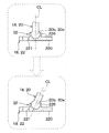
- the rotor 750 is rotationally displaced so that the first inlet side space 711a is passed through the rotor hole 752 and one of the flow path holes 723, 724, 725. It can communicate with any of the outlet side spaces 712b, 712d, and 712e. That is, the flow path switching valve 70 rotates and displaces the rotor 750 to allow the low-temperature heat medium flowing in from the first inlet portion 700A to flow out from any one of the plurality of outlet portions 700B, 700D, and 700E. Can be done.
- the flow path switching valve 70 rotates the rotor 750 to rotate and displace the first inlet side space 711a, the first outlet side space 712b, the second outlet side space 712d, and the third outlet side space. It can communicate with any one of the 712e.
- the low-temperature heat medium flowing in from the first inlet portion 700A has a passage configuration in which it flows out from the first outlet portion 700B, a passage configuration in which it flows out from the second outlet portion 700D, and a passage configuration in which it flows out from the third outlet portion 700E. It is possible to switch to any one passage configuration.
- the second inlet side space 712c can be communicated with any one of the plurality of outlet side spaces via the communication groove 754.
- the outlet side space for communicating the first inlet side space 711a and the outlet side space 712c for communicating with the second entrance side space 712c are communicated with each other.
- the side space is a different space.
- the second inlet side space 712c can be communicated with any one of the second outlet side space 712d and the third outlet side space 712e. ..
- the low-temperature heat medium flowing in from the second inlet portion 700C can be switched to any one of a passage configuration in which the low-temperature heat medium flows out from the second outlet portion 700D and a passage configuration in which the low-temperature heat medium flows out from the third outlet portion 700E. ..
- the low-temperature heat medium shaft 740 flowing into the second inlet side space 712c is uniaxially oriented from the other side to one side.
- the flow toward is turned in the opposite direction at the communication groove 754.
- the low temperature heat medium flows from one side to the other side in the axial direction DRa of the shaft 740.
- This also applies to the passage configuration in which the low-temperature heat medium flowing in from the second inlet portion 700C is discharged from the third outlet portion 700E.
- the rotor 750 is formed on opposite sides to each other. Therefore, the rotor 750 is arranged inside the main body 701, which is a housing, so that the pressure Ps1 of the first inlet side space 711a and the pressure Ps2 of the second inlet side space 712c act in opposite directions. become.
- the flow path switching valve 70 can allow the low-temperature heat medium flowing into the inside from the first inlet portion 700A to flow out from the first outlet portion 700B.
- the low-temperature heat medium flowing into the inside from the second inlet portion 700C is discharged from the second outlet portion 700D and the third outlet portion 700E. It is possible to switch between the passage configuration.
- the indoor air conditioning unit 500 is a unit for blowing out appropriately temperature-controlled blown air W to an appropriate location in the vehicle interior in the temperature adjusting device 1.
- the indoor air conditioning unit 500 is arranged inside the instrument panel (that is, the instrument panel) at the frontmost part of the vehicle interior.
- the indoor air conditioning unit 500 has a casing 501 that forms an air passage for the blown air W.
- An indoor blower 502, an indoor evaporator 207, a heater core 304, and the like are arranged in the air passage formed in the casing 501.
- the casing 501 is made of a resin (for example, polypropylene) having a certain degree of elasticity and excellent strength.
- An inside / outside air switching device 503 is arranged on the most upstream side of the blown air flow of the casing 501.
- the inside / outside air switching device 503 switches and introduces the air inside the vehicle interior (that is, the inside air) and the air outside the vehicle interior (that is, the outside air) into the casing 501.
- the operation of the electric actuator for driving the inside / outside air switching device 503 is controlled by the control signal output from the control device 600.
- An indoor blower 502 is arranged on the downstream side of the blower air flow of the inside / outside air switching device 503.
- the indoor blower 502 blows the air sucked through the inside / outside air switching device 503 toward the vehicle interior.
- the indoor blower 502 is an electric blower that drives a fan with an electric motor.
- the rotation speed (that is, the blowing capacity) of the indoor blower 502 is controlled by the control voltage output from the control device 600.
- the air mix door 504 is arranged on the downstream side of the blast air flow of the indoor evaporator 207 and on the upstream side of the blast air flow of the heater core 304.
- the air mix door 504 adjusts the air volume ratio between the air volume passing through the heater core 304 and the air volume passing through the cold air bypass passage 505 in the blown air W after passing through the indoor evaporator 207.
- the operation of the electric actuator for driving the air mix door is controlled by a control signal output from the control device 600.
- a mixing space 506 is provided on the downstream side of the blown air flow of the heater core 304 to mix the blown air W heated by the heater core 304 and the blown air W not heated by the heater core 304 through the cold air bypass passage 505. Has been done. Further, an opening hole (not shown) for blowing out the air-conditioned air mixed in the mixing space 506 into the vehicle interior is arranged at the most downstream portion of the blown air flow of the casing 501.
- the temperature of the conditioned air mixed in the mixing space 506 can be adjusted by adjusting the ratio of the air volume through which the air mix door 504 passes through the heater core 304 and the air volume passing through the cold air bypass passage 505. .. Then, the temperature of the blown air W blown out from each opening hole into the vehicle interior can be adjusted.
- the opening holes As the opening holes, a face opening hole, a foot opening hole, and a defroster opening hole (none of which are shown) are provided.
- the face opening hole is an opening hole for blowing air-conditioning air toward the upper body of the occupant in the vehicle interior.
- the foot opening hole is an opening hole for blowing air-conditioning air toward the feet of the occupant.
- the defroster opening hole is an opening hole for blowing air-conditioning air toward the inner surface of the window glass on the front surface of the vehicle.
- a blowout mode switching door (not shown) is arranged on the upstream side of these opening holes.
- the blow-out mode switching door switches the opening holes for blowing out the air-conditioning air by opening and closing each opening hole.
- the operation of the electric actuator for driving the blowout mode switching door is controlled by a control signal output from the control device 600.
- a control sensor group 610 is connected to the input side of the control device 600.
- the control sensor group 610 includes an internal air temperature detection unit that detects the vehicle interior temperature (internal air temperature) Tr, a battery temperature detection unit that detects the temperature of the battery BT, and an in-vehicle device temperature detection unit that detects the temperature of the in-vehicle device CE. Etc. are included.
- the equipment cooling mode is an operation mode in which the refrigerating cycle device 200 is operated to air-condition the vehicle interior and the battery BT is cooled by the low-temperature heat medium cooled by the refrigerating cycle device 200. ..
- the control device 600 operates the compressor 201, the high-pressure refrigerant discharged from the compressor 201 flows into the radiator 202.
- the control device 600 adjusts the refrigerant discharge capacity of the compressor 201 so that the temperature of the blown air W cooled by the indoor evaporator 207 becomes the target evaporator temperature TEO.
- the target evaporator temperature TEO is determined based on the detection signal of the sensor group 610 connected to the control device 600 with reference to the control map stored in the control device 600 in advance.
- This control map is configured so that the target evaporator temperature TEO is equal to or higher than the frost formation suppression temperature (for example, 1 ° C.) in order to suppress the frost formation of the indoor evaporator 207.
- the flow of the refrigerant flowing out of the radiator 202 is branched at the refrigerant branching portion 203.
- One of the refrigerants branched at the refrigerant branching portion 203 is depressurized by the first expansion valve 204 and flows into the chiller 206.
- the control device 600 adjusts the throttle opening of the first expansion valve 204 so that the temperature of the low-temperature heat medium flowing out of the heat medium passage 402 of the chiller 206 approaches the target cooling temperature TBO.
- the other refrigerant branched at the refrigerant branching portion 203 is depressurized by the second expansion valve 205 and flows into the indoor evaporator 207.
- the control device 600 adjusts the throttle opening of the second expansion valve 205 so that the refrigerant sucked into the compressor 201 approaches a predetermined standard superheat degree KSH (for example, 5 ° C.). Therefore, in the equipment cooling mode, the refrigerant evaporation temperature in the indoor evaporator 207 and the refrigerant evaporation temperature in the chiller 206 may be the same.
- the refrigerant flowing into the indoor evaporator 207 absorbs heat from the blown air W blown from the indoor blower 502 and evaporates. As a result, the blown air W is cooled.
- the refrigerant flowing out of the indoor evaporator 207 flows into the refrigerant merging portion 209 via the evaporation pressure adjusting valve 208.
- the refrigerant merging section 209 merges the flow of the refrigerant flowing out of the indoor evaporator 207 and the flow of the refrigerant flowing out of the chiller 206, and causes the flow out to the suction side of the compressor 201.
- the control device 600 when the control device 600 operates the high temperature side pump 301, the high temperature heat medium pumped from the high temperature side pump 301 flows into the heat medium passage 302 of the radiator 202.
- the high-temperature heat medium flowing into the heat medium passage 302 exchanges heat with the high-pressure refrigerant and is heated.
- the high-temperature heat medium flowing out of the radiator 202 flows into the high-temperature side switching valve 310 and is divided into a flow that flows into the high-temperature side radiator 303 and a flow that flows from the high-temperature side switching valve 310 into the heater core 304.
- the high-temperature heat medium that has flowed into the high-temperature side radiator 303 exchanges heat with the outside air OA blown from the outside air fan and dissipates heat. As a result, the high-temperature heat medium flowing through the high-temperature side radiator 303 is cooled. The high-temperature heat medium flowing out of the high-temperature side radiator 303 flows into the high-temperature side confluence portion 307.
- the high-temperature heat medium that has flowed into the heater core 304 exchanges heat with the blown air W that has passed through the indoor evaporator 207 and dissipates heat.
- the blown air W cooled by the indoor evaporator 207 is reheated.
- the control device 600 adjusts the opening degree of the air mix door 504 so that the blowing temperature of the blowing air W blown into the vehicle interior approaches the target blowing temperature TAO.
- the high-temperature heat medium flowing out of the heater core 304 flows into the high-temperature side merging portion 307.
- the high-temperature side merging portion 307 merges the high-temperature heat medium flowing out from the heater core 304 and the high-temperature heat medium flowing out from the high-temperature side radiator 303, and causes them to flow out to the fluid suction side of the high-temperature side pump 301.
- the low-temperature heat medium flowing out of the chiller 206 flows into the inside from the first inlet portion 700A of the flow path switching valve 70 and flows out from the first outlet portion 700B.
- the low-temperature heat medium flowing out from the first outlet portion 700B flows into the cooling water passage 405 of the battery BT.
- the heat medium that has flowed into the cooling water passage 405 of the battery BT absorbs the waste heat of the battery BT when flowing through the cooling water passage 405. As a result, the battery BT is cooled.
- the low-temperature heat medium flowing out from the cooling water passage 405 of the battery BT flows into the inside from the second inlet portion 700C of the flow path switching valve 70 and flows out from the third outlet portion 700E.
- the low-temperature heat medium flowing out from the third outlet portion 700E is guided to the suction side of the low-temperature side pump 401 via the short-circuit heat medium passage 440 and the low-temperature side merging portion 407.
- the low temperature heat medium discharged from the low temperature side pump 401 passes through the heat medium passage 402 of the chiller 206 and is passed through the flow path switching valve 70. It flows into the first entrance portion 700A of.
- the low-temperature heat medium that has flowed into the first inlet portion 700A of the flow path switching valve 70 flows out from the first outlet portion 700B of the flow path switching valve 70, and then flows out through the cooling water passage 405 of the battery BT, and then the flow path switching valve 70. It flows into the second entrance portion 700C of.
- the low-temperature heat medium that has flowed into the second inlet portion 700C flows out from the second outlet portion 700D of the flow path switching valve 70, and is then sucked into the low-temperature side pump 401 again via the low-temperature side radiator 403.
- the high-pressure refrigerant discharged from the compressor 201 is cooled by the radiator 202 until it becomes a supercooled liquid-phase refrigerant, as in the equipment cooling mode. Further, the high temperature heat medium flowing through the heat medium passage 302 of the radiator 202 is heated.
- the refrigerant flowing out of the radiator 202 flows into the refrigerant branching portion 203.
- the refrigerant flowing into the refrigerant branch portion 203 is depressurized by the second expansion valve 205 and flows into the indoor evaporator 207.
- the control device 600 adjusts the throttle opening degree of the second expansion valve 205 in the same manner as in the equipment cooling mode.
- the low-pressure refrigerant that has flowed into the indoor evaporator 207 absorbs heat from the blown air W and evaporates, as in the equipment cooling mode. As a result, the blown air W is cooled.
- the refrigerant flowing out of the indoor evaporator 207 is sucked into the compressor 201 via the evaporation pressure adjusting valve 208 and the refrigerant merging portion 209.
- the control device 600 controls the operation of the constituent equipment in the same manner as in the equipment cooling mode.
- the outlet side heat medium temperature THC of the high temperature heat medium approaches the reference outlet side heat medium temperature KTHC.
- the control device 600 operates the low temperature side pump 401
- the low temperature heat medium pumped from the low temperature side pump 401 flows into the heat medium passage 402 of the chiller 206.
- the first expansion valve 204 since the first expansion valve 204 is in the fully closed state, the low temperature heat medium flowing into the heat medium passage 402 of the chiller 206 flows out without exchanging heat with the low pressure refrigerant.
- the low-temperature heat medium flowing out of the chiller 206 flows into the inside from the first inlet portion 700A of the flow path switching valve 70 and flows out from the first outlet portion 700B.
- the low-temperature heat medium flowing out from the first outlet portion 700B flows into the cooling water passage 405 of the battery BT.
- the heat medium that has flowed into the cooling water passage 405 of the battery BT absorbs the waste heat of the battery BT when flowing through the cooling water passage 405. As a result, the battery BT is cooled.
- the low-temperature heat medium flowing out of the cooling water passage 405 of the battery BT flows into the inside from the second inlet portion 700C of the flow path switching valve 70 and flows out from the second outlet portion 700D.
- the low temperature heat medium flowing out from the second outlet portion 700D flows into the low temperature side radiator 403.
- the low-temperature heat medium that has flowed into the low-temperature side radiator 403 is blown from the outside air fan and exchanges heat with the outside air OA after passing through the high-temperature side radiator 303 to dissipate heat. As a result, the low temperature heat medium flowing through the low temperature side radiator 403 is cooled. The low-temperature heat medium flowing out of the low-temperature side radiator 403 is guided to the suction side of the low-temperature side pump 401 via the low-temperature side merging portion 407.
- the blown air W cooled by the indoor evaporator 207 can be reheated by the heater core 304 and blown out into the vehicle interior by operating as described above. Therefore, as in the equipment cooling mode, the blown air W adjusted to an appropriate temperature can be blown out into the vehicle interior to realize comfortable air conditioning. Further, in the outside air cooling mode, the battery BT can be cooled by allowing the low temperature heat medium cooled by exchanging heat with the outside air in the low temperature side radiator 403 to flow into the cooling water passage 405 of the battery BT.
- the control device 600 causes the low temperature heat medium flowing in from the first inlet portion 700A to flow out from the third outlet portion 700E. May be good. According to this, the low temperature heat medium flowing out from the heat medium passage 402 of the chiller 206 can be returned to the suction side of the low temperature side pump 401 via the short circuit heat medium passage 440 and the low temperature side merging portion 407.
- the outside air endothermic mode is an operation mode in which the refrigerating cycle device 200 is operated to heat the interior of the vehicle without cooling the battery BT.
- the outside air endothermic mode is an operation mode executed at a low outside air temperature (for example, when the temperature is 10 ° C. or lower).
- control device 600 controls the operation of the flow path switching valve 70 so that the low temperature heat medium flowing in from the first inlet portion 700A flows out from the second outlet portion 700D. Further, the control device 600 brings the second expansion valve 205 into a fully closed state. Further, the control device 600 adjusts the opening degree of the air mix door 504 so as to fully close the cold air bypass passage 505.
- the low temperature heat medium discharged from the low temperature side pump 401 passes through the heat medium passage 402 of the chiller 206 and is passed through the flow path switching valve 70. It flows into the first entrance portion 700A of.
- the low-temperature heat medium that has flowed into the first inlet portion 700A of the flow path switching valve 70 flows out from the second outlet portion 700D of the flow path switching valve 70, and is then sucked into the low-temperature side pump 401 again via the low-temperature side radiator 403.
- the high-pressure refrigerant discharged from the compressor 201 is cooled by the radiator 202 until it becomes a supercooled liquid-phase refrigerant, as in the equipment cooling mode. Further, the high temperature heat medium flowing through the heat medium passage 302 of the radiator 202 is heated.
- the refrigerant flowing out of the radiator 202 flows into the refrigerant branching portion 203.
- the second expansion valve 205 is fully closed, so that the refrigerant flowing into the refrigerant branch 203 is depressurized by the first expansion valve 204 and flows into the chiller 206.
- the control device 600 adjusts the throttle opening degree of the first expansion valve 204 so that the refrigerant evaporation temperature in the chiller 206 is lower than the outside air temperature.
- the low-pressure refrigerant flowing into the chiller 206 absorbs heat from the low-temperature heat medium flowing through the heat medium passage 402 and evaporates, as in the equipment cooling mode. As a result, the low temperature heat medium is cooled.
- the refrigerant flowing out of the chiller 206 is sucked into the compressor 201 via the refrigerant merging portion 209.
- the control device 600 controls the operation of the constituent equipment in the same manner as in the equipment cooling mode.
- the outlet side heat medium temperature THC of the high temperature heat medium approaches the reference outlet side heat medium temperature KTHC.
- the control device 600 when the control device 600 operates the low temperature side pump 401, the low temperature heat medium pumped from the low temperature side pump 401 flows into the heat medium passage 402 of the chiller 206.
- the low-temperature heat medium flowing into the chiller 206 exchanges heat with the low-pressure refrigerant and is cooled to a temperature lower than the outside air temperature.
- the low-temperature heat medium that has flowed into the low-temperature side radiator 403 is blown from the outside air fan and exchanges heat with the outside air OA after passing through the high-temperature side radiator 303 to absorb heat.
- the temperature of the low-temperature heat medium flowing through the low-temperature side radiator 403 rises so as to approach the outside air temperature.
- the low-temperature heat medium flowing out of the low-temperature side radiator 403 is guided to the suction side of the low-temperature side pump 401 via the low-temperature side merging portion 407.
- the blown air W heated by the heater core 304 can be blown out into the vehicle interior by operating as described above. Therefore, in the outside air endothermic mode, it is possible to realize heating of the vehicle interior without cooling the battery BT.
- the control device 600 is provided so that the temperature of the in-vehicle device CE is maintained within an appropriate temperature range regardless of the various operation modes described above. Controls the operation of various controlled devices. Specifically, the control device 600 operates the equipment pump 411 so as to exert a predetermined pumping capacity regardless of the various operation modes described above.
- the flow rate adjusting valve 412 for the device is set to an appropriate opening degree, and the low temperature side switching valve 430 is set to the low temperature side of the low temperature heat medium of the cooling passage 410 for the device.
- the low temperature side switching valve 430 opens the first flow path hole 141 and displaces the rotor 22 at a position that closes the second flow path hole 142. According to this, the low-temperature heat medium cooled by the low-temperature side radiator 403 can flow into the cooling water passage 406 of the in-vehicle device CE. As a result, the in-vehicle device CE can be cooled by the low-temperature heat medium cooled by the outside air.
- the flow rate adjusting valve 412 for the device is fully closed, and the low temperature heat medium of the cooling passage 410 for the device bypasses the low temperature side switching valve 430 for the device.
- the low temperature side switching valve 430 displaces the rotor 22 at a position where the first flow path hole 141 is closed and the second flow path hole 142 is opened. According to this, the low-temperature heat medium flowing out from the cooling water passage 406 of the in-vehicle device CE can be returned to the inlet side of the cooling water passage 406 again via the device bypass passage 420.
- the in-vehicle device CE can be warmed up by the self-heating of the in-vehicle device CE.
- frost may adhere to the outer surface of the low temperature side radiator 403. If frost adheres to the low temperature side radiator 403, the amount of heat absorbed from the outside air decreases, so that proper operation of the temperature adjusting device 1 cannot be realized.
- the temperature adjusting device 1 switches the operation mode to the defrosting mode when the frosting condition that frost adheres to the low temperature side radiator 403 is satisfied.
- the defrosting mode is a mode for removing frost adhering to the low temperature radiator 403.
- the frosting condition is, for example, a condition that is satisfied when the temperature difference between the low temperature heat mediums around the low temperature radiator 403 is equal to or lower than a predetermined temperature.
- the condition is an example, and the frosting condition may be another condition.
- the temperature adjusting device 1 operates the equipment pump 411 so as to exert a predetermined pumping capacity in the defrosting mode. Then, the temperature adjusting device 1 sets the flow rate adjusting valve 412 for the equipment to an appropriate opening degree, and switches the low temperature side switching valve 430 to a setting in which the low temperature heat medium of the cooling passage 410 for the equipment flows to the radiator 403 on the low temperature side. For example, the low temperature side switching valve 430 opens the first flow path hole 141 and displaces the rotor 22 at a position that closes the second flow path hole 142. As a result, the frost adhering to the low temperature side radiator 403 can be removed by allowing the low temperature heat medium that has been heated when passing through the cooling water passage 406 of the in-vehicle device CE to flow into the low temperature side radiator 403.
- the temperature adjusting device 1 described above can realize comfortable air conditioning in the vehicle interior by switching various operation modes, and can adjust the battery BT and the in-vehicle device CE to an appropriate temperature.
- the high temperature side switching valve 310 and the low temperature side switching valve 430 of this embodiment are configured in the same manner as the valve device 10 described in the first embodiment. Therefore, the high temperature side switching valve 310 and the low temperature side switching valve 430 can obtain the same effects as those of the valve device 10 described in the first embodiment.
- the high-temperature side switching valve 310 increases or decreases the opening degree of the first flow path hole 141 and the opening degree of the second flow path hole 142 by the rotor 22, so that the high-temperature heat passes through the high-temperature side radiator 303.
- the flow rate ratio of the medium and the high temperature heat medium passing through the heater core 304 can be appropriately adjusted.
- the resolution of opening degree control of the high temperature side switching valve 310 is large, the flow rate ratio of the high temperature heat medium passing through the high temperature side radiator 303 and the high temperature heat medium passing through the heater core 304 cannot be adjusted appropriately, and the vehicle interior The temperature variation of the blown air becomes large. In this case, as the operation of the air mix door 504 and the like increases, the power consumption increases and the power consumption rate in the vehicle deteriorates.
- the high temperature side switching valve 310 of the present embodiment can suppress fluid leakage due to a change in the attitude of the shaft 20, so that the flow rate of the high temperature heat medium passing through the heater core 304 can be finely adjusted. That is, according to the high temperature side switching valve 310 of the present embodiment, the above-mentioned problems can be solved.
- the low temperature side switching valve 430 is a low temperature heat medium and equipment that passes through the low temperature side radiator 403 by increasing or decreasing the opening degree of the first flow path hole 141 and the opening degree of the second flow path hole 142 by the rotor 22.
- the flow rate ratio of the low temperature heat medium passing through the detour passage 420 can be appropriately adjusted.
- the total amount of the fluid heated by the in-vehicle device CE can be appropriately guided to the low temperature side radiator 403. According to this, since the defrosting of the low temperature side radiator 403 can be performed in a short time, it is possible to sufficiently suppress the influence on the vehicle interior air conditioning and the equipment temperature control due to the defrosting operation.
- the flow path switching valve 70 is not formed by combining a plurality of on-off valves, three-way valves, etc., it is unlikely to cause an increase in size. Therefore, it is possible to suppress the increase in size of the second fluid circulation circuit 400 to which the flow path switching valve 70 is applied.
- the flow path switching valve 70 has the same configuration as the valve device 10 of the first embodiment, and the connection structure of the shaft 740 and the rotor 750 is such that the shaft 20 of the valve device 10 and the rotor 22 are connected. It is configured in the same way as the structure. Therefore, the flow path switching valve 70 can obtain the same effect as the valve device 10 exerted by the valve device 10 described in the first embodiment. That is, the flow path switching valve 70 can realize the optimum distribution of the low temperature heat medium by increasing or decreasing the opening degree of each flow path hole 722 to 725 by the rotor 22.
- the second fluid circulation circuit 400 if the low-temperature heat medium in the flow path switching valve 70 cannot be properly distributed, the temperature variation of each battery constituting the battery BT becomes large. In this case, the deterioration of the battery BT is accelerated, so that the cruising range of the vehicle is reduced. It is conceivable to mount an extra battery in consideration of the deterioration of the battery BT, but in this case, the initial cost will increase significantly.
- the flow path switching valve 70 of the present embodiment can realize the optimum distribution of the low temperature heat medium, so that the above-mentioned problems can be solved.
- the pressure of the rotor 750 in the first inlet side space 711a and the pressure in the second inlet side space 712c act in opposite directions to each other. Therefore, in the flow path switching valve 70, when the pressure of one of the low temperature heat medium flowing in from the first inlet portion 700A and the low temperature heat medium flowing in from the second inlet portion 700C changes, the pressure acting before and after the rotor 750. The balance will change. Such a change in pressure balance can be a factor that hinders the adhesion between the rotor 750 and the stator 720.
- the flow path switching valve 70 of the present embodiment has a configuration in which the rotor 750 is pressed toward the stator 720 by the urging member 770. Therefore, even if the pressure of the fluid flowing in from the inlets 700A and 700C changes, the posture of the rotor 750 can be maintained in the posture of being in contact with the stator 720.
- the high temperature side switching valve 310, the low temperature side switching valve 430, and the flow path switching valve 70 have the same configuration as the valve device 10 of the present disclosure, but the temperature adjusting device 1 has the same configuration as the valve device 10 of the present disclosure. Not limited to this.
- the temperature adjusting device 1 at least one of the high temperature side switching valve 310, the low temperature side switching valve 430, and the flow path switching valve 70 may have the same configuration as the valve device 10 of the present disclosure.
- the valve device 10 of the present disclosure can be applied to a fluid circulation circuit (for example, a refrigeration cycle device 200) different from the first fluid circulation circuit 300 and the second fluid circulation circuit 400.
- the high temperature side radiator 303, the heater core 304, and the cooling water passage 405 of the battery BT are arranged in parallel on the downstream side of the high temperature side pump 301 so that the battery BT can be warmed up.
- the circuit configuration may be connected.
- the valve device 10 of the present disclosure can be applied as a flow path switching valve for switching the circuit configuration of the first fluid circulation circuit 300.
- Such a flow path switching valve can be realized by a four-way valve having one inlet portion and three outlet portions. That is, the flow path switching valve includes an inlet portion through which the high-temperature heat medium flows, a first outlet portion through which the high-temperature heat medium flows out to the high-temperature side radiator 303, a second outlet portion through which the high-temperature heat medium flows out into the heater core 304, and a battery BT. A third outlet is provided to allow the high-temperature heat medium to flow out to the cooling water passage 405.
- the flow path switching valve rotates and displaces the rotor 22 to pass through the high temperature heat medium passing through the high temperature side radiator 303, the high temperature heat medium passing through the heater core 304, and the high temperature heat medium passing through the cooling water passage 405 of the battery BT.
- the flow rate ratio of the heating medium is adjusted.
- the flow path switching valve is a radiator on the high temperature side by increasing or decreasing the opening degree of the first flow path hole, the opening degree of the second flow path hole, and the opening degree of the third flow path hole by the rotor 22.
- the flow rate ratio of the high temperature heat medium passing through each of the 303, the heater core 304, and the cooling water passage 405 of the battery BT is adjusted.
- the first flow path hole, the second flow path hole, and the third flow path hole are flow path holes formed in the stator 14.
- the first flow path hole is a flow path hole through which the high temperature heat medium flowing into the high temperature side radiator 303 passes.
- the second flow path hole is a flow path hole through which the high-temperature heat medium flowing into the heater core 304 passes.
- the third flow path hole is a flow path hole through which the high-temperature heat medium flowing into the cooling water passage 405 of the battery BT passes.
- the temperature adjusting device 1 is applied to an electric vehicle, but the application target of the temperature adjusting device 1 is not limited to the electric vehicle.
- the temperature adjusting device 1 can be widely applied to, for example, a moving body other than an electric vehicle, a stationary device, or the like. These things are the same in the valve device 10 of the 1st to 7th embodiments.
- valve device 10 can also be applied to the high temperature side switching valve 310, the low temperature side switching valve 430, the flow path switching valve 70, and the like described in the eighth embodiment.
- one end side portion 20a of the shaft 20 is supported by the one end side bearing portion 126, and the other end side portion 20b of the shaft 20 is supported by the other end side bearing portion 144. It is desirable, but not limited to.
- the valve device 10 may have a structure in which at least one of the one end side portion 20a and the other end side bearing portion 144 of the shaft 20 is not supported by the bearing portion, for example.
- the gap G between the fitting hole 223 of the rotor 22 and the fitting portion 20c of the shaft 20 is formed between the bearing portion 144 on the other end side and the fitting portion 20c, which are holding portions. It is desirable, but not limited to, to be larger than the gap of.
- the gap G between the fitting hole 223 of the rotor 22 and the fitting portion 20c of the shaft 20 is equivalent to the gap between the bearing portion 144 on the other end side, which is the holding portion, and the fitting portion 20c. It may be sized.
- stator 14 and the rotor 22 are made of ceramic, but the present invention is not limited to this.
- the stator 14 and the rotor 22 may be made of a material other than ceramic.
- valve device 10 includes a three-way valve having one fluid inlet and two fluid outlets, but the valve device 10 is not limited to this.
- the valve device 10 of the present disclosure may be composed of a three-way valve having two fluid inlets and one fluid outlet.
- valve device 10 is illustrated to be composed of a three-way valve, but the valve device 10 is not limited to the three-way valve.
- the valve device 10 of the present disclosure may be configured as a five-way valve, such as the flow path switching valve 70.
- the valve device 10 of the present disclosure may be configured as, for example, a flow control valve or an on-off valve having one fluid inlet and one fluid outlet. In this case, one flow path hole is formed in the stator 14.
- the valve device 10 of the present disclosure is, for example, a multi-way valve having one fluid inlet and three or more fluid outlets, a multi-way valve having three or more fluid inlets and one fluid outlet, a plurality of fluid inlets and a plurality of fluids. It may be composed of a multi-sided valve having an outlet or the like.
- the housing 12 and the stator 14 are formed separately, but the present invention is not limited to this.
- a portion corresponding to the stator 14 may be integrally formed in the housing 12.
- the elastic member is exemplified as the urging member 26, but the urging member 26 is not limited to this.
- the urging member 26 may be made of a member other than the elastic member as long as the rotor 22 can be pressed toward the stator 14.
- the compression spring 261 is preferably arranged so as to surround the outside of the shaft 20, but is not limited to this.
- the compression spring 261 may be arranged, for example, around the shaft 20.
- valve device 10 in which the flow path hole is formed in the stator 14 formed separately from the housing 12 is illustrated, but the valve device 10 is not limited to this.
- a flow path hole may be formed directly with respect to the housing 12.
- the sliding portion on which the rotor 22 slides in the housing 12 has a smaller coefficient of linear expansion such as ceramic and is excellent in wear resistance as compared with the constituent materials of the portions other than the sliding portion. It is desirable that it is made of material.
- the elements constituting the embodiment are not necessarily essential except when it is clearly stated that they are essential and when they are clearly considered to be essential in principle.
- the valve device rotates the flow path forming portion, the driving portion, the shaft, the rotor, the urging member, and the shaft. It is provided with a connecting structure that is tiltably connected to the child.
- the connecting structure includes a fitting structure in which the fitting portion of the shaft is fitted into the fitting hole provided in the rotor.
- the fitting hole has a size such that a gap is formed between the fitting hole and the shaft so that the shaft can be tilted while the fitting portion is fitted.
- the shaft has one end side portion where the rotational force is transmitted from the drive portion and the other end side portion opposite to the one end side portion in the axial direction of the shaft.
- the flow path forming portion is provided with a holding portion for holding the other end side portion.
- the gap between the fitting hole and the fitting portion is larger than the gap between the holding portion and the fitting portion.
- the valve device includes a housing in which the rotor and the flow path forming portion are housed.
- the flow path forming portion includes a disk-shaped stator in which a flow path hole is formed and is arranged so as not to rotate with respect to the housing, and a seal member arranged between the stator and the housing. ..
- the sealing property between the stator and the housing can be ensured by the sealing member.
- the rotor may be in an inclined posture, but even in this case, the stator follows the rotor due to the deformation of the seal member. It becomes possible to tilt.
- the seal member is interposed between the stator and the housing, the adhesion between the stator and the rotor can be ensured, and fluid leakage in the valve device can be sufficiently suppressed. Can be done.
- the connecting structure includes a universal joint that connects the shaft and the rotor so that the angle between the sliding surface and the axis of the shaft can be changed.
- the shaft can be slidably connected to the rotor.
- the urging member is composed of an elastic member that elastically deforms in the axial direction of the shaft. According to this, it is possible to sufficiently secure a load for pressing the sliding surface of the rotor toward the opening surface of the flow path forming portion, so that the contact state between the sliding surface and the opening surface can be easily maintained.
- the elastic member is composed of a coil-shaped compression spring that applies a compressive load to the rotor. In this way, the elastic member can be composed of a compression spring.
- the shaft is arranged inside the compression spring. According to this, since the load of the compression spring on the rotor is suppressed from being biased in the circumferential direction of the shaft, the contact state between the sliding surface and the opening surface can be easily maintained.
- the valve device includes a coiled torsion spring that urges the rotor to one side in the circumferential direction around the axis of the shaft.
- the compression spring is arranged inside the torsion spring and has a larger number of turns than the torsion spring.
- the shaft is provided with a flange portion protruding in the radial direction of the shaft.
- the compression spring is arranged in a compressed state between the rotor and the flange portion so as to rotate with the rotor.
- the compression spring does not function as a torsion spring, it is possible to prevent an unnecessary force from acting on the rotor in the circumferential direction around the axis of the shaft.
- the urging member not only urges the rotor toward the flow path forming portion, but also urges the rotor on one side in the circumferential direction around the axis of the shaft. It is composed of elastic members that are connected to each other.
- the elastic member has a function as a torsion spring in addition to a function as a compression spring. Therefore, it is possible to suppress the positional deviation between the rotor and the shaft in the circumferential direction of the shaft while maintaining the posture of the rotor in contact with the flow path forming portion without increasing the number of parts of the valve device. ..
- the valve device is a fluid circulation circuit including an outdoor heat exchanger that exchanges heat between the fluid and the air outside the vehicle interior and an indoor heat exchanger that exchanges heat between the air flowing into the vehicle interior and the fluid. Applies.
- the valve device is connected to the fluid inlet side of the outdoor heat exchanger and is connected to the first outlet portion where the fluid flows out to the outdoor heat exchanger and the fluid inlet side of the indoor heat exchanger to supply the fluid to the indoor heat exchanger.
- a second outlet for outflow is provided.
- the valve device is connected to the fluid outlet side of the outdoor heat exchanger and the fluid outlet side of the indoor heat exchanger, and includes an inlet portion through which fluid flows from the outdoor heat exchanger and the indoor heat exchanger.
- the flow rate ratio of the fluid passing through the outdoor heat exchanger and the fluid passing through the indoor heat exchanger is adjusted by rotationally displaced the rotor.
- the flow rate ratio between the fluid passing through the outdoor heat exchanger and the fluid passing through the indoor heat exchanger can be adjusted by the valve device.
- the valve device of the present disclosure can suppress fluid leakage due to a change in the posture of the shaft, it is possible to accurately adjust the flow rate ratio in each heat exchanger.
- the temperature of the air flowing into the vehicle interior is finely adjusted by adjusting the flow rate ratios of the indoor heat exchanger and the outdoor heat exchanger. It becomes possible.
- the valve device bypasses the outdoor heat exchanger that exchanges heat between the fluid and the air outside the vehicle interior, the temperature control unit that adjusts the temperature of the heat generating device by the fluid, and the outdoor heat exchanger. It is applied to a fluid circulation circuit including a bypass part through which a fluid flows.
- the valve device is connected to the fluid inlet side of the outdoor heat exchanger and is connected to the first outlet portion where the fluid flows out to the outdoor heat exchanger and the second outlet portion which is connected to the fluid inlet side of the bypass portion and causes the fluid to flow out to the bypass portion. It is equipped with an outlet.
- the valve device is connected to the fluid outlet side of the temperature control section, has an inlet section where the fluid flows in from the temperature control section, and by rotating and displaced the rotor, it passes through the fluid passing through the bypass section and the outdoor heat exchanger.
- the flow rate ratio of the fluid to be used is adjusted.
- the flow rate ratio between the fluid passing through the outdoor heat exchanger and the fluid passing through the bypass portion can be adjusted by the valve device.
- the valve device of the present disclosure can suppress fluid leakage due to a change in the posture of the shaft, it is possible to accurately adjust the flow rate ratio in the outdoor heat exchanger and the bypass portion.
- the entire amount of the fluid heated in the temperature control section can be appropriately guided to the outdoor heat exchanger. According to this, since the outdoor heat exchanger can be defrosted in a short time, it is possible to sufficiently suppress the influence on the vehicle interior air conditioning and the equipment temperature control due to the defrosting operation.
- the valve device includes a first inlet portion into which the fluid flows in, a second inlet portion into which the fluid flows in, and at least one outlet portion in which the fluid flows out to the outside.
- the valve device includes a housing in which a first inlet-side space communicating with the first inlet portion and a second inlet-side space communicating with the second inlet portion are formed inside.
- the rotor is arranged inside the housing so that the pressure in the first inlet side space and the pressure in the second inlet side space act in opposite directions.
- valve device configured in this way, if the pressure of one of the fluid flowing in from the first inlet portion and the fluid flowing in from the second inlet portion changes, the pressure balance acting before and after the rotor changes.
- valve device of the present disclosure has a configuration in which the rotor is pressed toward the flow path forming portion by the urging member, the posture of the rotor can be changed even if the pressure of the fluid flowing in from each inlet portion changes. It can be maintained in a posture in contact with the flow path forming portion.
- the fluid circulation circuit includes a plurality of devices through which the fluid passes and a valve device for adjusting the flow rate of the fluid passing through the plurality of devices.
- the valve device rotates about a predetermined axis by a flow path forming portion in which at least one flow path hole through which a fluid passes is formed, a drive portion that outputs a rotational force, and a rotational force output by the drive unit. It has a shaft and.
- the valve device has a sliding surface that slides relative to the opening surface of the flow path forming portion where the flow path hole opens, and a rotor that increases or decreases the opening degree of the flow path hole as the shaft rotates. It has an urging member that urges the rotor toward the flow path forming portion.
- the valve device includes a connecting structure in which the shaft is tiltably connected to the rotor so that the contact state between the sliding surface and the opening surface is maintained regardless of the posture of the shaft.
Landscapes
- Engineering & Computer Science (AREA)
- General Engineering & Computer Science (AREA)
- Mechanical Engineering (AREA)
- Chemical & Material Sciences (AREA)
- Combustion & Propulsion (AREA)
- Physics & Mathematics (AREA)
- Thermal Sciences (AREA)
- Electrically Driven Valve-Operating Means (AREA)
- Multiple-Way Valves (AREA)
- Sliding Valves (AREA)
Abstract
A valve device (10) that comprises: a channel formation part (14, 720) that has formed therein at least one channel hole (141, 142, 722, 723, 724, 725) through which a fluid is to pass; and a drive part (16) that outputs rotational force. The valve device also comprises a shaft (20, 740) that rotates around a prescribed center line (CL) due to the rotational force outputted by the drive part. The valve device also comprises a rotor (22, 750) that: has a sliding surface (220, 751) that slides relative to an opening surface (140, 721) that is the portion of the channel formation part at which the channel hole opens; and, in association with the rotation of the shaft, increases/decreases the degree to which the channel hole is open. The valve device also comprises an urging member (26, 770) that urges the rotor toward the channel formation part. The valve device also comprises a connection structure (24, 28, 32, 760, 780) that tiltably connects the shaft to the rotor such that the state of contact between the sliding surface and the opening surface is maintained regardless of the posture of the shaft.
Description
本出願は、2019年9月10日に出願された日本特許出願番号2019-164851号に基づくもので、ここにその記載内容が参照により組み入れられる。
This application is based on Japanese Patent Application No. 2019-164851 filed on September 10, 2019, the contents of which are incorporated herein by reference.
本開示は、バルブ装置および当該バルブ装置を備える流体循環回路に関する。
The present disclosure relates to a valve device and a fluid circulation circuit including the valve device.
従来、シャフトに連結される第1バルブプレートとハウジングに回転不能に配置された第2バルブプレートとの相対的な位置関係を変化させることで、第2バルブプレートに形成された流路孔の開度を調整するバルブ装置が知られている(例えば、特許文献1参照)。
Conventionally, by changing the relative positional relationship between the first valve plate connected to the shaft and the second valve plate non-rotatably arranged in the housing, the flow path hole formed in the second valve plate is opened. A valve device for adjusting the degree is known (see, for example, Patent Document 1).
ところで、特許文献1の記載のバルブ装置は、シャフトと第1バルブプレートとが一体に構成されているので、何らかの要因によってシャフトが傾くと、シャフトとともに第1バルブプレートが傾いてしまい、各バルブプレートの密着性が損なわれてしまう。このようなシャフトの姿勢変化は、バルブ装置における意図しない流体漏れを招く要因となることから好ましくない。このことは本発明者らの鋭意検討の末に見出された。
本開示は、シャフトの姿勢変化による流体漏れを抑えることが可能なバルブ装置および流体循環回路を提供することを目的とする。 By the way, in the valve device described inPatent Document 1, since the shaft and the first valve plate are integrally configured, if the shaft is tilted for some reason, the first valve plate is tilted together with the shaft, and each valve plate is tilted. Adhesion is impaired. Such a change in the attitude of the shaft is not preferable because it causes an unintended fluid leakage in the valve device. This was discovered after diligent studies by the present inventors.
It is an object of the present disclosure to provide a valve device and a fluid circulation circuit capable of suppressing fluid leakage due to a change in shaft attitude.
本開示は、シャフトの姿勢変化による流体漏れを抑えることが可能なバルブ装置および流体循環回路を提供することを目的とする。 By the way, in the valve device described in
It is an object of the present disclosure to provide a valve device and a fluid circulation circuit capable of suppressing fluid leakage due to a change in shaft attitude.
本開示の1つの観点によれば、バルブ装置は、
流体が通過する流路孔が少なくとも1つ形成された流路形成部と、
回転力を出力する駆動部と、
駆動部が出力する回転力によって所定の軸心を中心に回転するシャフトと、
流路形成部のうち流路孔が開口する開口面に相対して摺動する摺動面を有し、シャフトの回転に伴って流路孔の開度を増減する回転子と、
回転子を流路形成部に向けて付勢する付勢部材と、
シャフトの姿勢によらず摺動面と開口面との接触状態が維持されるようにシャフトを回転子に対して傾動可能に連結する連結構造と、を備える。 According to one aspect of the present disclosure, the valve device is
A flow path forming portion in which at least one flow path hole through which a fluid passes is formed, and a flow path forming portion.
A drive unit that outputs rotational force and
A shaft that rotates around a predetermined axis by the rotational force output by the drive unit,
A rotor having a sliding surface that slides relative to the opening surface of the flow path forming portion and that increases or decreases the opening degree of the flow path hole as the shaft rotates.
An urging member that urges the rotor toward the flow path forming part,
It is provided with a connecting structure in which the shaft is tiltably connected to the rotor so that the contact state between the sliding surface and the opening surface is maintained regardless of the posture of the shaft.
本開示の別の観点によれば、流体循環回路は、
流体が通過する複数の機器と、
複数の機器を通過する流体の流量を調整するバルブ装置と、を備え、
バルブ装置は、
流体が通過する流路孔が少なくとも1つ形成された流路形成部と、
回転力を出力する駆動部と、
駆動部が出力する回転力によって所定の軸心を中心に回転するシャフトと、
流路形成部のうち流路孔が開口する開口面に相対して摺動する摺動面を有し、シャフトの回転に伴って流路孔の開度を増減する回転子と、
回転子を流路形成部に向けて付勢する付勢部材と、
シャフトの姿勢によらず摺動面と開口面との接触状態が維持されるようにシャフトを回転子に対して傾動可能に連結する連結構造と、を含んでいる。 According to another aspect of the present disclosure, the fluid circulation circuit is
With multiple devices through which fluids pass,
Equipped with a valve device that regulates the flow rate of fluid passing through multiple devices,
The valve device is
A flow path forming portion in which at least one flow path hole through which a fluid passes is formed, and a flow path forming portion.
A drive unit that outputs rotational force and
A shaft that rotates around a predetermined axis by the rotational force output by the drive unit,
A rotor having a sliding surface that slides relative to the opening surface of the flow path forming portion and that increases or decreases the opening degree of the flow path hole as the shaft rotates.
An urging member that urges the rotor toward the flow path forming part,
It includes a connecting structure in which the shaft is tiltably connected to the rotor so that the contact state between the sliding surface and the opening surface is maintained regardless of the posture of the shaft.
このように、シャフトを回転子に対して傾動可能に連結する連結構造を備えていれば、何らかの要因によってシャフトが傾いても、回転子と流路形成部との密着性を確保することができる。また、付勢部材によって回転子が流路形成部に向けて押し付けられるので、回転子の姿勢を流路形成部に接する姿勢に維持することができる。したがって、本開示のバルブ装置および流体循環回路は、シャフトの姿勢変化による流体漏れを抑制することができる。
In this way, if a connecting structure for tiltably connecting the shaft to the rotor is provided, the adhesion between the rotor and the flow path forming portion can be ensured even if the shaft is tilted for some reason. .. Further, since the rotor is pressed toward the flow path forming portion by the urging member, the posture of the rotor can be maintained in a posture in contact with the flow path forming portion. Therefore, the valve device and the fluid circulation circuit of the present disclosure can suppress fluid leakage due to a change in the attitude of the shaft.
なお、各構成要素等に付された括弧付きの参照符号は、その構成要素等と後述する実施形態に記載の具体的な構成要素等との対応関係の一例を示すものである。
Note that the reference symbols in parentheses attached to each component or the like indicate an example of the correspondence between the component or the like and the specific component or the like described in the embodiment described later.
以下、本開示の実施形態について図面を参照して説明する。なお、以下の実施形態において、先行する実施形態で説明した事項と同一もしくは均等である部分には、同一の参照符号を付し、その説明を省略する場合がある。また、実施形態において、構成要素の一部だけを説明している場合、構成要素の他の部分に関しては、先行する実施形態において説明した構成要素を適用することができる。以下の実施形態は、特に組み合わせに支障が生じない範囲であれば、特に明示していない場合であっても、各実施形態同士を部分的に組み合わせることができる。
Hereinafter, embodiments of the present disclosure will be described with reference to the drawings. In the following embodiments, the same reference numerals may be assigned to parts that are the same as or equivalent to those described in the preceding embodiments, and the description thereof may be omitted. Further, when only a part of the component is described in the embodiment, the component described in the preceding embodiment can be applied to the other part of the component. The following embodiments can be partially combined with each other as long as the combination does not cause any trouble, even if not explicitly stated.
(第1実施形態)
本実施形態について、図1~図9を参照して説明する。本実施形態では、本開示のバルブ装置10を、車両に搭載される車両用の制御バルブに適用した例について説明する。図1に示すバルブ装置10は、図示しないが、流体(本例では、冷却水)を走行用動力源およびラジエータ等に循環させる流体循環回路に適用され、流体循環回路を循環する流体が流れる。 (First Embodiment)
This embodiment will be described with reference to FIGS. 1 to 9. In this embodiment, an example in which thevalve device 10 of the present disclosure is applied to a control valve for a vehicle mounted on a vehicle will be described. Although not shown, the valve device 10 shown in FIG. 1 is applied to a fluid circulation circuit that circulates a fluid (cooling water in this example) to a traveling power source, a radiator, or the like, and a fluid that circulates in the fluid circulation circuit flows.
本実施形態について、図1~図9を参照して説明する。本実施形態では、本開示のバルブ装置10を、車両に搭載される車両用の制御バルブに適用した例について説明する。図1に示すバルブ装置10は、図示しないが、流体(本例では、冷却水)を走行用動力源およびラジエータ等に循環させる流体循環回路に適用され、流体循環回路を循環する流体が流れる。 (First Embodiment)
This embodiment will be described with reference to FIGS. 1 to 9. In this embodiment, an example in which the
バルブ装置10は、流体循環回路のうちバルブ装置10を介した流通経路における流体の流量を増減することができるとともに、当該流通経路における流体の流れを遮断することもできる。流体としては、例えばエチレングリコールを含むLLCなどが用いられる。なお、LLCはLong Life Coolant の略称である。
The valve device 10 can increase or decrease the flow rate of the fluid in the flow path through the valve device 10 in the fluid circulation circuit, and can also block the flow of the fluid in the flow path. As the fluid, for example, LLC containing ethylene glycol is used. LLC is an abbreviation for Long Life Coolant.
図1および図2に示すように、バルブ装置10は、外殻を形成するハウジング12を有する。バルブ装置10は、流体が流入する入口部121、流体を流出させる第1出口部122、流体を流出させる第2出口部123がハウジング12に設けられた三方弁で構成されている。バルブ装置10は、単に流路切替弁としての機能だけでなく、入口部121から第1出口部122へ流れる流体と、入口部121から第2出口部123へ流れる流体との流量割合を調整する流量調整弁としても機能する。
As shown in FIGS. 1 and 2, the valve device 10 has a housing 12 that forms an outer shell. The valve device 10 is composed of a three-way valve having an inlet portion 121 for inflowing fluid, a first outlet portion 122 for discharging fluid, and a second outlet portion 123 for discharging fluid in the housing 12. The valve device 10 not only functions as a flow path switching valve, but also adjusts the flow rate ratio of the fluid flowing from the inlet portion 121 to the first outlet portion 122 and the fluid flowing from the inlet portion 121 to the second outlet portion 123. It also functions as a flow control valve.
バルブ装置10は、後述するシャフト20の軸心CLまわりに円盤状の弁体が回転することで、バルブ開閉動作を行うディスクバルブとして構成されている。なお、本実施形態は、後述するシャフト20の軸心CLに沿う方向を軸心方向DRaとし、当該軸心方向DRaに直交するとともに軸心方向DRaから放射状に伸びる方向を径方向DRrとして各種構成等を説明する。また、本実施形態は、軸心CLまわりの方向を周方向DRcとして各種構成等を説明する。
The valve device 10 is configured as a disc valve that opens and closes a valve by rotating a disk-shaped valve body around the axis CL of the shaft 20, which will be described later. In this embodiment, the direction along the axis CL of the shaft 20 described later is defined as the axial direction DRa, and the direction orthogonal to the axial direction DRa and extending radially from the axial direction DRa is defined as the radial DRr. Etc. will be explained. Further, in this embodiment, various configurations and the like will be described with the direction around the axial center CL as the circumferential direction DRc.
図3に示すように、バルブ装置10は、ハウジング12の内側に、固定子14、駆動部16、回転部18、付勢部材26等が収容されている。
As shown in FIG. 3, in the valve device 10, a stator 14, a drive unit 16, a rotating unit 18, an urging member 26, and the like are housed inside the housing 12.
ハウジング12は、回転しない非回転部材である。ハウジング12は、例えば樹脂材料によって形成されている。ハウジング12は、軸心方向DRaに沿って延びる有底筒状の本体部120と本体部120の開口部120aを閉塞する本体カバー部124とを有している。
The housing 12 is a non-rotating member that does not rotate. The housing 12 is made of, for example, a resin material. The housing 12 has a bottomed tubular main body 120 extending along the axial direction DRa and a main body cover 124 that closes the opening 120a of the main body 120.
本体部120は、底面を形成する底壁部120bおよび軸心CLまわりを囲む側壁部120cを有している。側壁部120cには、底壁部120bよりも開口部120aに近い位置に入口部121が形成され、開口部120aよりも底壁部120bに近い位置に第1出口部122および第2出口部123が形成されている。
The main body 120 has a bottom wall 120b forming the bottom surface and a side wall 120c surrounding the axis CL. In the side wall portion 120c, an inlet portion 121 is formed at a position closer to the opening 120a than the bottom wall portion 120b, and a first outlet portion 122 and a second outlet portion 123 are formed at a position closer to the bottom wall portion 120b than the opening 120a. Is formed.
側壁部120cの内側には、軸心CLに近づくように突き出る環状の突起部120dが形成されている。突起部120dは、本体部120の内側に固定子14を配置するために設けられている。突起部120dには、図示しないが、回り止め用のピンが設けられ、当該ピンによって、固定子14の周方向DRcへの移動が規制されている。なお、固定子14の回り止めは、回り止め用のピン以外の手段によって実現されていてもよい。
Inside the side wall portion 120c, an annular protrusion 120d that protrudes so as to approach the axial center CL is formed. The protrusion 120d is provided to arrange the stator 14 inside the main body 120. Although not shown, the protrusion 120d is provided with a pin for preventing rotation, and the pin regulates the movement of the stator 14 in the circumferential direction DRc. The detent of the stator 14 may be realized by means other than the detent pin.
本体部120の内側は、固定子14によって入口側空間120eと出口側空間120fとに仕切られている。入口側空間120eは、ハウジング12の内側にて入口部121に連通する空間である。出口側空間120fは、ハウジング12内側にて第1出口部122および第2出口部123に連通する空間である。
The inside of the main body 120 is partitioned by a stator 14 into an inlet side space 120e and an exit side space 120f. The entrance side space 120e is a space that communicates with the entrance portion 121 inside the housing 12. The outlet side space 120f is a space that communicates with the first outlet portion 122 and the second outlet portion 123 inside the housing 12.
また、本体部120の内側には、出口側空間120fを第1出口側空間120gと第2出口側空間120hとに仕切る板状の仕切部125が設定されている。仕切部125は、出口側空間120fを径方向DRrに沿って横断するように設けられている。
Further, inside the main body 120, a plate-shaped partition 125 for partitioning the outlet side space 120f into the first outlet side space 120g and the second outlet side space 120h is set. The partition portion 125 is provided so as to cross the outlet side space 120f along the radial direction DRr.
固定子14は、軸心方向DRaを厚み方向とする円盤状の部材で構成されている。固定子14は、後述する回転子22が摺動する表面としての開口面140を有する。開口面140は、後述する回転子22の摺動面220に対応するシール面である。
The stator 14 is composed of a disk-shaped member whose thickness direction is the axial direction DRa. The stator 14 has an opening surface 140 as a surface on which the rotor 22, which will be described later, slides. The opening surface 140 is a sealing surface corresponding to the sliding surface 220 of the rotor 22, which will be described later.
固定子14は、ハウジング12の構成材料に比較して、線膨張係数が小さく、且つ、耐摩耗性に優れた材料で形成されていることが望ましい。固定子14は、ハウジング12よりも硬度が高い高硬度材料で構成されている。具体的には、固定子14はセラミックで構成されている。なお、固定子14は、開口面140を形成する部位だけが、ハウジング12の構成材料に比較して、セラミック等の線膨張係数が小さく、且つ、耐摩耗性に優れた材料で形成されていてもよい。
It is desirable that the stator 14 is made of a material having a small coefficient of linear expansion and excellent wear resistance as compared with the constituent material of the housing 12. The stator 14 is made of a high hardness material having a hardness higher than that of the housing 12. Specifically, the stator 14 is made of ceramic. In the stator 14, only the portion forming the opening surface 140 is formed of a material having a small coefficient of linear expansion such as ceramic and excellent wear resistance as compared with the constituent material of the housing 12. May be good.
また、固定子14は、流体が通過する流路孔が形成された流路形成部を構成する。図4に示すように、固定子14には、流体が通過する第1流路孔141および第2流路孔142が形成されている。
Further, the stator 14 constitutes a flow path forming portion in which a flow path hole through which a fluid passes is formed. As shown in FIG. 4, the stator 14 is formed with a first flow path hole 141 and a second flow path hole 142 through which a fluid passes.
第1流路孔141および第2流路孔142は、シャフト20の軸心CLと重ならないように、固定子14のうちシャフト20の軸心CLから離れた位置に形成されている。第1流路孔141および第2流路孔142は、セクタ状(すなわち、扇形状)の貫通孔であり、第1流路孔141および第2流路孔142は、入口側空間120eと出口側空間120fとを連通させる連通路として機能する。なお、第1流路孔141および第2流路孔142は、セクタ状に限らず、円形状や楕円形状等の他の形状になっていてもよい。
The first flow path hole 141 and the second flow path hole 142 are formed at positions of the stator 14 away from the axis CL of the shaft 20 so as not to overlap with the axis CL of the shaft 20. The first flow path hole 141 and the second flow path hole 142 are sector-shaped (that is, fan-shaped) through holes, and the first flow path hole 141 and the second flow path hole 142 are an inlet side space 120e and an outlet. It functions as a communication passage that communicates with the side space 120f. The first flow path hole 141 and the second flow path hole 142 are not limited to the sector shape, and may have other shapes such as a circular shape and an elliptical shape.
具体的には、第1流路孔141は、第1出口側空間120gに連通するように、固定子14のうち、第1出口側空間120gに対応する部位に設けられている。また、第2流路孔142は、第2出口側空間120hに連通するように、固定子14のうち、第2出口側空間120hに対応する部位に設けられている。
Specifically, the first flow path hole 141 is provided in a portion of the stator 14 corresponding to the first outlet side space 120 g so as to communicate with the first outlet side space 120 g. Further, the second flow path hole 142 is provided in a portion of the stator 14 corresponding to the second outlet side space 120h so as to communicate with the second outlet side space 120h.
図3に戻り、固定子14の略中心部分には、後述するシャフト20の他端側部位20bを保持する保持孔143が形成されている。シャフト20の他端側部位20bは、シャフト20において駆動部16から回転力が伝えられる一端側部位20aとは軸心方向DRaにおいて反対側となる部位である。
Returning to FIG. 3, a holding hole 143 for holding the other end side portion 20b of the shaft 20, which will be described later, is formed in the substantially central portion of the stator 14. The other end side portion 20b of the shaft 20 is a portion of the shaft 20 that is opposite to the one end side portion 20a to which the rotational force is transmitted from the drive unit 16 in the axial direction DRa.
保持孔143には、シャフト20の他端側部位20bを回転自在に支持する他端側軸受部144が配置されている。他端側軸受部144は、滑り面によって他端側部位20bを受ける滑り軸受で構成されている。なお、他端側軸受部144は、滑り軸受ではなく、玉軸受等の他の軸受で構成されていてもよい。本実施形態のバルブ装置10は、保持孔143および他端側軸受部144によって保持部が構成されている。
In the holding hole 143, the other end side bearing portion 144 that rotatably supports the other end side portion 20b of the shaft 20 is arranged. The other end side bearing portion 144 is composed of a slide bearing that receives the other end side portion 20b by the sliding surface. The other end side bearing portion 144 may be composed of other bearings such as ball bearings instead of the slide bearings. In the valve device 10 of the present embodiment, the holding portion is composed of the holding hole 143 and the bearing portion 144 on the other end side.
駆動部16は、回転力を出力するための機器である。駆動部16は、駆動源としてのモータ161と、モータ161の出力をシャフト20に伝達する動力伝達部材としてのギア部162とを有している。
The drive unit 16 is a device for outputting a rotational force. The drive unit 16 has a motor 161 as a drive source and a gear unit 162 as a power transmission member that transmits the output of the motor 161 to the shaft 20.
モータ161は、電力供給を受けることにより回転作動する駆動源である。モータ161は、例えばサーボモータまたはブラシレスモータが採用される。モータ161は、モータ161と電気的に連結したバルブ制御部17からの制御信号に従って回転する。
The motor 161 is a drive source that rotates by receiving electric power. As the motor 161, for example, a servo motor or a brushless motor is adopted. The motor 161 rotates according to a control signal from the valve control unit 17 electrically connected to the motor 161.
バルブ制御部17は、非遷移的実体的記憶媒体であるメモリ、およびプロセッサなどを有するコンピュータである。バルブ制御部17は、メモリに記憶されたコンピュータプログラムを実行するとともに、コンピュータプログラムに従って種々の制御処理を実行する。
The valve control unit 17 is a computer having a memory which is a non-transitional substantive storage medium, a processor, and the like. The valve control unit 17 executes a computer program stored in the memory and executes various control processes according to the computer program.
ギア部162は、複数の歯車を有している。ギア部162は、複数の歯車の互いの噛み合いにより、モータ161の回転作動を回転部18へ伝達し回転部18を回転させる。具体的には、ギア部162は、モータ161の回転作動を回転部18のシャフト20へ伝達し、回転部18を構成するシャフト20および回転子22を回転させる。本実施形態のギア部162は、歯車としてヘリカルギアまたは平歯車を含むギア機構で構成されている。なお、ギア部162は、上述のギア機構に限らず、例えば、歯車としてウォームおよびウォームホイールを有するウォームギアで構成されていてもよい。
The gear unit 162 has a plurality of gears. The gear unit 162 transmits the rotational operation of the motor 161 to the rotating unit 18 by meshing the plurality of gears with each other to rotate the rotating unit 18. Specifically, the gear unit 162 transmits the rotational operation of the motor 161 to the shaft 20 of the rotating unit 18 to rotate the shaft 20 and the rotor 22 constituting the rotating unit 18. The gear portion 162 of the present embodiment is composed of a gear mechanism including a helical gear or a spur gear as a gear. The gear portion 162 is not limited to the gear mechanism described above, and may be composed of, for example, a worm gear having a worm and a worm wheel as gears.
回転部18は、バルブ装置10において、駆動部16の出力によってシャフト20の軸心CLを中心に回転する。回転部18は、シャフト20と、弁体としての回転子22と、シャフト20に回転子22を連結する中間子24とを有している。
The rotating unit 18 rotates about the axis CL of the shaft 20 by the output of the driving unit 16 in the valve device 10. The rotating portion 18 has a shaft 20, a rotor 22 as a valve body, and a meson 24 that connects the rotor 22 to the shaft 20.
シャフト20は、駆動部16が出力する回転力によって所定の軸心CLを中心に回転する回転軸である。シャフト20は軸心方向DRaに沿って延伸する。シャフト20は、軸心方向DRaの一方側に駆動部16から回転力が伝えられる一端側部位20aおよび一端側部位20aとは軸心方向DRaにて反対となる他端側部位20bを有している。一端側部位20aはギア部162に連結されている。また、シャフト20は、一端側部位20aと他端側部位20bとの間の部位が、中間子24を介して回転子22に相対回転不能に連結されている。
The shaft 20 is a rotating shaft that rotates around a predetermined axial center CL by the rotational force output by the drive unit 16. The shaft 20 extends along the axial direction DRa. The shaft 20 has one end side portion 20a to which the rotational force is transmitted from the drive unit 16 on one side in the axial direction DRa and the other end side portion 20b opposite to the one end side portion 20a in the axial direction DRa. There is. The one end side portion 20a is connected to the gear portion 162. Further, in the shaft 20, a portion between one end side portion 20a and the other end side portion 20b is connected to the rotor 22 via a meson 24 so as to be relatively non-rotatable.
シャフト20は、一端側部位20aが本体カバー部124に設けられた一端側軸受部126によって回転可能に支持されるとともに、他端側部位20bが他端側軸受部144によって回転可能に支持されている。一端側軸受部126は、滑り面によって一端側部位20aを受ける滑り軸受で構成されている。なお、一端側軸受部126は、滑り軸受ではなく、玉軸受等の他の軸受で構成されていてもよい。
In the shaft 20, one end side portion 20a is rotatably supported by one end side bearing portion 126 provided in the main body cover portion 124, and the other end side portion 20b is rotatably supported by the other end side bearing portion 144. There is. The one end side bearing portion 126 is composed of a slide bearing that receives the one end side portion 20a by the sliding surface. The one-end side bearing portion 126 may be composed of other bearings such as ball bearings instead of the slide bearings.
シャフト20は、シャフト20の姿勢によらず固定子14の開口面140と回転子22の摺動面220との接触状態が維持されるように、回転子22に対して傾動可能に連結されている。シャフト20と回転子22との連結構造の詳細は後述する。なお、「傾動」は、一方向に傾いて動くことを意味する。
The shaft 20 is tiltably connected to the rotor 22 so that the contact state between the opening surface 140 of the stator 14 and the sliding surface 220 of the rotor 22 is maintained regardless of the posture of the shaft 20. There is. Details of the connection structure between the shaft 20 and the rotor 22 will be described later. In addition, "tilt" means to move by tilting in one direction.
回転子22は、シャフト20の回転に伴って第1流路孔141の開度および第2流路孔142の開度を増減する弁体である。なお、第1流路孔141の開度は、第1流路孔141が開かれている度合いであり、第1流路孔141の全開を100%、全閉を0%として表される。第1流路孔141の全開は、例えば、第1流路孔141が回転子22に全く塞がれていない状態である。第1流路孔141の全閉は、例えば、第1流路孔141の全体が回転子22に塞がれている状態である。第2流路孔142の開度は、第1流路孔141の開度と同様である。
The rotor 22 is a valve body that increases or decreases the opening degree of the first flow path hole 141 and the opening degree of the second flow path hole 142 as the shaft 20 rotates. The opening degree of the first flow path hole 141 is the degree to which the first flow path hole 141 is opened, and is represented as 100% when the first flow path hole 141 is fully opened and 0% when the first flow path hole 141 is fully closed. Fully opening the first flow path hole 141 is, for example, a state in which the first flow path hole 141 is not blocked by the rotor 22 at all. The fully closed first flow path hole 141 is, for example, a state in which the entire first flow path hole 141 is completely closed by the rotor 22. The opening degree of the second flow path hole 142 is the same as the opening degree of the first flow path hole 141.
回転子22は、軸心方向DRaを厚み方向とする円盤状の部材で構成されている。回転子22は、軸心方向DRaにおいて固定子14に相対するように入口側空間120eに配置されている。回転子22は、固定子14の開口面140に相対して摺動する摺動面220を有する。摺動面220は、固定子14の開口面140をシールするシール面である。
The rotor 22 is composed of a disk-shaped member whose thickness direction is the axial direction DRa. The rotor 22 is arranged in the inlet side space 120e so as to face the stator 14 in the axial direction DRa. The rotor 22 has a sliding surface 220 that slides relative to the opening surface 140 of the stator 14. The sliding surface 220 is a sealing surface that seals the opening surface 140 of the stator 14.
回転子22は、ハウジング12の構成材料に比較して、線膨張係数が小さく、且つ、耐摩耗性に優れた材料で形成されていることが望ましい。回転子22は、ハウジング12よりも硬度が高い高硬度材料で構成されている。具体的には、回転子22はセラミックで構成されている。なお、回転子22は、摺動面220を形成する部位だけが、ハウジング12の構成材料に比較して、セラミック等の線膨張係数が小さく、且つ、耐摩耗性に優れた材料で形成されていてもよい。
It is desirable that the rotor 22 is made of a material having a small coefficient of linear expansion and excellent wear resistance as compared with the constituent material of the housing 12. The rotor 22 is made of a high hardness material having a hardness higher than that of the housing 12. Specifically, the rotor 22 is made of ceramic. In the rotor 22, only the portion forming the sliding surface 220 is made of a material having a small coefficient of linear expansion such as ceramic and excellent wear resistance as compared with the constituent material of the housing 12. You may.
回転子22には、シャフト20の軸心CLに対して偏心した位置に回転子孔221が形成されている。回転子孔221は、軸心方向DRaに貫通する貫通孔である。回転子孔221は、回転子22のシャフト20の軸心CLまわりを回転させた際に、回転子22において第1流路孔141および第2流路孔142と軸心方向DRaに重なり合う部位に形成されている。
The rotor 22 has a rotor hole 221 formed at a position eccentric with respect to the axial center CL of the shaft 20. The rotor hole 221 is a through hole penetrating in the axial direction DRa. The rotor hole 221 is located at a portion of the rotor 22 that overlaps the first flow path hole 141 and the second flow path hole 142 in the axial direction DRa when the rotor 22 is rotated around the axis CL of the shaft 20. It is formed.
バルブ装置10は、回転子孔221が第1流路孔141と軸心方向DRaに重なり合うように回転子22を回転させると、第1流路孔141が開放される。また、バルブ装置10は、回転子孔221が第2流路孔142と軸心方向DRaに重なり合うように回転子22を回転させると、第2流路孔142が開放される。
In the valve device 10, when the rotor 22 is rotated so that the rotor hole 221 overlaps the first flow path hole 141 in the axial direction DRa, the first flow path hole 141 is opened. Further, in the valve device 10, when the rotor 22 is rotated so that the rotor hole 221 overlaps the second flow path hole 142 in the axial direction DRa, the second flow path hole 142 is opened.
回転子22は、第1流路孔141を通過する流体および第2流路孔142を通過する流体の流量割合を調整可能に構成されている。すなわち、回転子22は、第1流路孔141の開度が大きくなるにともなって第2流路孔142の開度が小さくなるように構成されている。
The rotor 22 is configured so that the flow rate ratio of the fluid passing through the first flow path hole 141 and the fluid passing through the second flow path hole 142 can be adjusted. That is, the rotor 22 is configured so that the opening degree of the second flow path hole 142 decreases as the opening degree of the first flow path hole 141 increases.
中間子24は、シャフト20に回転子22を連結する連結構造の一部を構成する。中間子24は、回転子22の自転を防止する自転防止機構としても機能する。中間子24は、他端側部位20bと回転子22との間に隙間が形成されるように回転子22をシャフト20に連結する。中間子24は、回転子22よりも軸心方向DRaにおいて一端側部位20aに近い位置に設けられている。
The meson 24 constitutes a part of the connecting structure for connecting the rotor 22 to the shaft 20. The meson 24 also functions as a rotation prevention mechanism for preventing the rotor 22 from rotating. The meson 24 connects the rotor 22 to the shaft 20 so that a gap is formed between the other end side portion 20b and the rotor 22. The meson 24 is provided at a position closer to the one end side portion 20a in the axial direction DRa than the rotor 22.
中間子24は、シャフト20の外周を覆う中間筒状部241および中間筒状部241から回転子22に向けて軸心方向DRaに沿って突き出る中間ピン242を有している。中間筒状部241は、シャフト20と一体に回転可能なように、圧入、嵌合、接着等の連結手段によってシャフト20に対して連結されている。中間ピン242は、シャフト20の回転を回転子22に伝える部材である。中間ピン242は、回転子22のうち摺動面220の反対側の表面に形成されたピン受部222に嵌め込むことが可能に構成されている。
The meson 24 has an intermediate tubular portion 241 that covers the outer periphery of the shaft 20 and an intermediate pin 242 that protrudes from the intermediate tubular portion 241 toward the rotor 22 along the axial direction DRa. The intermediate tubular portion 241 is connected to the shaft 20 by a connecting means such as press fitting, fitting, or bonding so that the intermediate tubular portion 241 can rotate integrally with the shaft 20. The intermediate pin 242 is a member that transmits the rotation of the shaft 20 to the rotor 22. The intermediate pin 242 is configured to be able to be fitted into the pin receiving portion 222 formed on the surface of the rotor 22 on the opposite side of the sliding surface 220.
このように構成される中間子24は、中間ピン242をピン受部222に嵌め込むことによって回転子22の自転を防止する構成になっている。なお、回転子22の自転防止機構は、上述のものに限らず、他の手段によって実現されていてもよい。
The meson 24 configured in this way is configured to prevent the rotor 22 from rotating by fitting the meson pin 242 into the pin receiving portion 222. The rotation prevention mechanism of the rotor 22 is not limited to the above-mentioned one, and may be realized by other means.
付勢部材26は、回転子22を流路形成部に対応する固定子14に向けて付勢する部材である。付勢部材26は、図5に示すように、回転子22に圧縮荷重を付与するコイル状の圧縮バネ261で構成されている。圧縮バネ261は、シャフト20の軸心方向DRaに弾性変形する弾性部材である。
The urging member 26 is a member that urges the rotor 22 toward the stator 14 corresponding to the flow path forming portion. As shown in FIG. 5, the urging member 26 is composed of a coil-shaped compression spring 261 that applies a compressive load to the rotor 22. The compression spring 261 is an elastic member that elastically deforms in the axial direction DRa of the shaft 20.
圧縮バネ261は、シャフト20の軸心CLまわりに巻かれて形成されている。すなわち、圧縮バネ261の内側にシャフト20が配置されている。圧縮バネ261は、駆動部16と回転子22との間に圧縮された状態で配置されている。
The compression spring 261 is formed by being wound around the axis CL of the shaft 20. That is, the shaft 20 is arranged inside the compression spring 261. The compression spring 261 is arranged in a compressed state between the drive unit 16 and the rotor 22.
具体的には、圧縮バネ261は、軸心方向DRaの一方側の端部が本体カバー部124に接し、軸心方向DRaの他方側の端部が回転子22に接するようにハウジング12の内側に配置されている。なお、圧縮バネ261は、トーションバネとして機能しないように、回転子22および本体カバー部124の少なくとも一方に対して固定されていない。
Specifically, the compression spring 261 is inside the housing 12 so that one end of the axial DRa is in contact with the main body cover portion 124 and the other end of the axial DRa is in contact with the rotor 22. Is located in. The compression spring 261 is not fixed to at least one of the rotor 22 and the main body cover portion 124 so as not to function as a torsion spring.
圧縮バネ261は、シャフト20の軸心CLに対して傾斜し難くなるように両端部がクローズエンドとなるバネが採用されている。クローズエンドとなるバネは、バネの据わりをよくするために、バネ端部の巻だけ巻角度を変えて隣の巻にバネ線の端部を付けたものである。なお、圧縮バネ261は、両端部がオープンエンドとなるバネが採用されていてもよい。
The compression spring 261 employs a spring whose both ends are closed ends so that it is difficult to incline with respect to the axial center CL of the shaft 20. The closed-end spring has the end of the spring wire attached to the adjacent winding by changing the winding angle only for the winding at the end of the spring in order to improve the installation of the spring. The compression spring 261 may employ a spring having open ends at both ends.
圧縮バネ261によって回転子22が固定子14に押し付けられることで、固定子14の開口面140と回転子22の摺動面220との接触状態が維持される。この接触状態は、固定子14の開口面140と回転子22の摺動面220とが面接触した状態である。
By pressing the rotor 22 against the stator 14 by the compression spring 261, the contact state between the opening surface 140 of the stator 14 and the sliding surface 220 of the rotor 22 is maintained. This contact state is a state in which the opening surface 140 of the stator 14 and the sliding surface 220 of the rotor 22 are in surface contact with each other.
ここで、面接触とは、開口面140および摺動面220がシャフト20の軸心CLを中心として周方向DRcに互いに90°以上離れた3点で接触している状態である。例えば、図6に示すように、回転子22は、開口面140および摺動面220が第1接点P1、第2接点P2、および第3接点P3で接するように、圧縮バネ261によって固定子14に押し付けられている。
Here, the surface contact is a state in which the opening surface 140 and the sliding surface 220 are in contact with each other at three points separated from each other by 90 ° or more with respect to the circumferential DRc about the axial center CL of the shaft 20. For example, as shown in FIG. 6, the rotor 22 has a stator 14 by a compression spring 261 so that the opening surface 140 and the sliding surface 220 are in contact with each other at the first contact P1, the second contact P2, and the third contact P3. Is pressed against.
ここで、図6に示すものは、第1流路孔141と第2流路孔142との間にて固定子14と回転子22とが接する接点を第1接点P1としている。
Here, in the one shown in FIG. 6, the contact point where the stator 14 and the rotor 22 are in contact between the first flow path hole 141 and the second flow path hole 142 is defined as the first contact point P1.
また、図6に示すものは、第1接点P1とシャフト20の軸心CLとを通る第1仮想線VL1と、第1仮想線VL1に直交するとともにシャフト20の軸心CLとを通る第2仮想線VL2とで、4つの領域A1、A2、A3、A4に区分している。そして、図6に示すものは、第1接点P1を介して隣り合う第1領域A1および第2領域A2以外の第3領域A3で固定子14と回転子22とが接する接点を第2接点P2とし、第4領域A4にて固定子14と回転子22とが接する接点を第3接点P3としている。なお、固定子14と回転子22とが接する第1接点P1、第2接点P2、第3接点P3は、図6に示されるものに限定されない。第1接点P1、第2接点P2、第3接点P3は、例えば、付勢部材26によって回転子22から固定子14に作用する荷重に基づいて規定されていてもよい。
Further, what is shown in FIG. 6 is a second virtual line VL1 that passes through the first contact P1 and the axial center CL of the shaft 20 and a second virtual line VL1 that is orthogonal to the first virtual line VL1 and passes through the axial center CL of the shaft 20. The virtual line VL2 is divided into four areas A1, A2, A3, and A4. Then, in FIG. 6, the contact point where the stator 14 and the rotor 22 are in contact with each other in the third region A3 other than the first region A1 and the second region A2 adjacent to each other via the first contact P1 is the second contact P2. The contact point where the stator 14 and the rotor 22 are in contact with each other in the fourth region A4 is the third contact point P3. The first contact P1, the second contact P2, and the third contact P3 in which the stator 14 and the rotor 22 are in contact with each other are not limited to those shown in FIG. The first contact P1, the second contact P2, and the third contact P3 may be defined based on, for example, the load acting on the stator 14 from the rotor 22 by the urging member 26.
続いて、本実施形態のシャフト20と回転子22との連結構造について図7を参照して説明する。図7は、図3のVII部分を拡大した部分拡大図である。
Subsequently, the connection structure of the shaft 20 and the rotor 22 of the present embodiment will be described with reference to FIG. 7. FIG. 7 is an enlarged partially enlarged view of the VII portion of FIG.
図7に示すように、シャフト20と回転子22との連結構造は、回転子22に設けられた嵌合孔223にシャフト20の一部を嵌め込む嵌合構造28を含んでいる。嵌合構造28は、回転子22の嵌合孔223に対してシャフト20の一部が隙間嵌となる嵌め合い構造になっている。
As shown in FIG. 7, the connecting structure between the shaft 20 and the rotor 22 includes a fitting structure 28 in which a part of the shaft 20 is fitted into the fitting hole 223 provided in the rotor 22. The fitting structure 28 has a fitting structure in which a part of the shaft 20 is gap-fitted with respect to the fitting hole 223 of the rotor 22.
本実施形態のシャフト20は、他端側部位20bの一部が、回転子22に設けられた嵌合孔223に嵌め込まれる嵌合部20cを構成している。この嵌合部20cは、他端側部位20bのうち径方向DRrにおいて回転子22と重なり合う部位である。
The shaft 20 of the present embodiment constitutes a fitting portion 20c in which a part of the other end side portion 20b is fitted into the fitting hole 223 provided in the rotor 22. The fitting portion 20c is a portion of the other end side portion 20b that overlaps with the rotor 22 in the radial DRr.
嵌合孔223は、シャフト20の一部を嵌合させた状態でシャフト20を傾動可能なように、シャフト20との間に隙間が形成される大きさになっている。すなわち、嵌合孔223は、その直径Φgがシャフト20の嵌合部20cの直径Φsよりも大きくなっている(すなわち、Φg>Φs)。
The fitting hole 223 has a size such that a gap is formed between the fitting hole 223 and the shaft 20 so that the shaft 20 can be tilted in a state where a part of the shaft 20 is fitted. That is, the diameter Φg of the fitting hole 223 is larger than the diameter Φs of the fitting portion 20c of the shaft 20 (that is, Φg> Φs).
また、嵌合孔223と嵌合部20cとの隙間は、シャフト20の保持部を構成する他端側軸受部144と嵌合部20cとの隙間よりも大きくなっている。具体的には、嵌合孔223の直径Φgと嵌合部20cの直径Φgとの差である嵌合寸法差ΔΦaは、他端側軸受部144の内径Φbと嵌合部20cの直径Φgとの差である軸寸法差ΔΦbよりも大きくなっている(すなわち、ΔΦa>ΔΦb)。
Further, the gap between the fitting hole 223 and the fitting portion 20c is larger than the gap between the other end side bearing portion 144 forming the holding portion of the shaft 20 and the fitting portion 20c. Specifically, the fitting dimension difference ΔΦa, which is the difference between the diameter Φg of the fitting hole 223 and the diameter Φg of the fitting portion 20c, is the inner diameter Φb of the bearing portion 144 on the other end side and the diameter Φg of the fitting portion 20c. It is larger than the shaft dimensional difference ΔΦb, which is the difference between the two (that is, ΔΦa> ΔΦb).
ここで、例えば、嵌合孔223は、円形状でない場合、上述の直径Φgが規定できなくなってしまう。このため、例えば、嵌合孔223が円形状でない場合、嵌合孔223の直径Φgを嵌合孔223と断面積が等しい円の直径(すなわち、等価直径)とし、上述の大小関係が設定されていてもよい。このことは、嵌合部20cや他端側軸受部144においても同様である。
Here, for example, if the fitting hole 223 is not circular, the diameter Φg described above cannot be specified. Therefore, for example, when the fitting hole 223 is not circular, the diameter Φg of the fitting hole 223 is set to the diameter of a circle having the same cross-sectional area as the fitting hole 223 (that is, the equivalent diameter), and the above-mentioned magnitude relationship is set. You may be. This also applies to the fitting portion 20c and the bearing portion 144 on the other end side.
図8に示すように、シャフト20および回転子22は、何らかの要因によって、実線で示す設計上の狙いの姿勢から破線で示す傾いた姿勢になってしまうことがある。シャフト20および回転子22が傾く要因としては、例えば、シャフト20の軸心方向DRaの寸法バラツキ、シャフト20の両端が別体の部材に保持されて構造になっていること等が挙げられる。このような構造では、本体カバー部124と本体部120と組み付け精度が充分でないと、一端側軸受部126と他端側軸受部144との相対的な位置が径方向DRrにずれ、シャフト20が傾いてしまう。
As shown in FIG. 8, the shaft 20 and the rotor 22 may change from the design target posture shown by the solid line to the tilted posture shown by the broken line due to some factor. Factors that cause the shaft 20 and the rotor 22 to tilt include, for example, dimensional variation in the axial direction DRa of the shaft 20, and a structure in which both ends of the shaft 20 are held by separate members. In such a structure, if the assembly accuracy of the main body cover portion 124 and the main body portion 120 is not sufficient, the relative positions of the one end side bearing portion 126 and the other end side bearing portion 144 are displaced in the radial direction DRr, and the shaft 20 is displaced. It tilts.
これに対して、付勢部材26による押付荷重を大きくして回転子22と固定子14との密着性を確保することが考えられるが、この場合、回転子22と固定子14との間での摺動抵抗が大きくなることで負荷トルクが増加してしまう。
On the other hand, it is conceivable to increase the pressing load by the urging member 26 to secure the adhesion between the rotor 22 and the stator 14, but in this case, between the rotor 22 and the stator 14. The load torque increases due to the increase in the sliding resistance of the.
そこで、本実施形態のバルブ装置10は、シャフト20の一部が隙間嵌となる嵌め合い構造で回転子22の嵌合孔223に嵌合されている。これによると、付勢部材26による押付荷重を大きくする必要がなく、負荷トルクの増大も抑制することができる。
Therefore, the valve device 10 of the present embodiment is fitted into the fitting hole 223 of the rotor 22 with a fitting structure in which a part of the shaft 20 is gap-fitted. According to this, it is not necessary to increase the pressing load by the urging member 26, and the increase in the load torque can be suppressed.
ここで、シャフト20の傾き角として設計上許容される最大角をシャフト傾斜角θとし、回転子22の傾き角として設計上許容される最大角を回転子傾斜角αとしたとき、嵌合孔223と嵌合部20cとの隙間Gが、以下の数式F1を満たしていることが望ましい。嵌合孔223と嵌合部20cとの隙間Gが、以下の数式F1を満たす場合、シャフト20や回転子22が設計範囲内で傾いたとしても、固定子14の開口面140と回転子22の摺動面220との面接触させることが可能となる。
Here, when the maximum angle allowed by design as the tilt angle of the shaft 20 is the shaft tilt angle θ and the maximum angle allowed by design as the tilt angle of the rotor 22 is the rotor tilt angle α, the fitting hole It is desirable that the gap G between the 223 and the fitting portion 20c satisfies the following mathematical formula F1. When the gap G between the fitting hole 223 and the fitting portion 20c satisfies the following mathematical formula F1, even if the shaft 20 and the rotor 22 are tilted within the design range, the opening surface 140 of the stator 14 and the rotor 22 It is possible to make surface contact with the sliding surface 220 of the above.
G≧T×tan(θ-α)・・・(F1)
また、嵌合孔223と嵌合部20cとの隙間Gは、シャフト20の一端側部位20aの回転中心と他端側部位20bの回転中心との径方向DRrでのズレ量として許容される許容ズレ量よりも大きくなるように設定されていてもよい。これによっても、設計範囲内において、回転子22と固定子14との密着性を確保することができる。 G ≧ T × tan (θ−α) ・ ・ ・ (F1)
Further, the gap G between thefitting hole 223 and the fitting portion 20c is an allowable amount of deviation in the radial DRr between the rotation center of the one end side portion 20a of the shaft 20 and the rotation center of the other end side portion 20b. It may be set to be larger than the deviation amount. This also ensures that the rotor 22 and the stator 14 are in close contact with each other within the design range.
また、嵌合孔223と嵌合部20cとの隙間Gは、シャフト20の一端側部位20aの回転中心と他端側部位20bの回転中心との径方向DRrでのズレ量として許容される許容ズレ量よりも大きくなるように設定されていてもよい。これによっても、設計範囲内において、回転子22と固定子14との密着性を確保することができる。 G ≧ T × tan (θ−α) ・ ・ ・ (F1)
Further, the gap G between the
次に、本実施形態のバルブ装置10の作動について説明する。バルブ装置10は、図3および図4に示すように、流体は、矢印Fiのように入口部121から入口側空間120eへ流入する。そして、第1流路孔141が開いている場合には、流体が入口側空間120eから第1流路孔141を介して第1出口側空間120gへ流れる。第1出口側空間120gへ流れ込んだ流体は、第1出口側空間120gから第1出口部122を介してバルブ装置10の外部へ矢印F1oのように流出する。この場合、第1流路孔141を通過する流体の流量は、第1流路孔141の開度に応じて定まる。すなわち、入口部121から第1流路孔141を介して第1出口部122へ流れる流体の流量は、第1流路孔141の開度が大きいほど大きくなる。
Next, the operation of the valve device 10 of the present embodiment will be described. In the valve device 10, as shown in FIGS. 3 and 4, the fluid flows from the inlet portion 121 into the inlet side space 120e as shown by the arrow Fi. Then, when the first flow path hole 141 is open, the fluid flows from the inlet side space 120e to the first outlet side space 120g via the first flow path hole 141. The fluid that has flowed into the first outlet side space 120 g flows out from the first outlet side space 120 g via the first outlet portion 122 to the outside of the valve device 10 as shown by an arrow F1o. In this case, the flow rate of the fluid passing through the first flow path hole 141 is determined according to the opening degree of the first flow path hole 141. That is, the flow rate of the fluid flowing from the inlet portion 121 to the first outlet portion 122 through the first flow path hole 141 increases as the opening degree of the first flow path hole 141 increases.
一方、第2流路孔142が開いている場合には、流体が入口側空間120eから第2流路孔142を介して第2出口側空間120hへ流入する。第2出口側空間120hへ流れ込んだ流体は第2出口側空間120hから第2出口部123を介してバルブ装置10の外部へ矢印F2oのように流出する。この場合、第2流路孔142を通過する流体の流量は、第2流路孔142の開度に応じて定まる。すなわち、入口部121から第2流路孔142を介して第2出口部123へ流れる流体の流量は、第2流路孔142の開度が大きいほど大きくなる。
On the other hand, when the second flow path hole 142 is open, the fluid flows from the inlet side space 120e into the second outlet side space 120h via the second flow path hole 142. The fluid that has flowed into the second outlet side space 120h flows out from the second outlet side space 120h to the outside of the valve device 10 via the second outlet portion 123 as shown by the arrow F2o. In this case, the flow rate of the fluid passing through the second flow path hole 142 is determined according to the opening degree of the second flow path hole 142. That is, the flow rate of the fluid flowing from the inlet portion 121 to the second outlet portion 123 through the second flow path hole 142 increases as the opening degree of the second flow path hole 142 increases.
以上説明した本実施形態のバルブ装置10は、シャフト20を回転子22に対して傾動可能に連結する連結構造を備えている。これによると、何らかの要因によってシャフト20が傾いても、回転子22と流路形成部を構成する固定子14との密着性を確保することが可能となる。
The valve device 10 of the present embodiment described above has a connecting structure in which the shaft 20 is tiltably connected to the rotor 22. According to this, even if the shaft 20 is tilted for some reason, it is possible to secure the adhesion between the rotor 22 and the stator 14 constituting the flow path forming portion.
ここで、単にシャフト20を回転子22に対して傾動可能に連結する場合、流体の圧力によって回転子22の姿勢が規定される。この場合、例えば、流体の圧力が変化すると、回転子22の姿勢が定まらず、回転子22と流路形成部を構成する固定子14との密着性の確保には不充分となってしまう。
Here, when the shaft 20 is simply connected to the rotor 22 so as to be tiltable, the posture of the rotor 22 is defined by the pressure of the fluid. In this case, for example, when the pressure of the fluid changes, the posture of the rotor 22 is not determined, and it becomes insufficient to secure the adhesion between the rotor 22 and the stator 14 constituting the flow path forming portion.
これに対して、本実施形態のバルブ装置10は、付勢部材26によって回転子22が固定子14に向けて押し付けられているので、回転子22の姿勢を固定子14に接する姿勢に維持することができる。
On the other hand, in the valve device 10 of the present embodiment, since the rotor 22 is pressed toward the stator 14 by the urging member 26, the posture of the rotor 22 is maintained in a posture in contact with the stator 14. be able to.
このように、本実施形態のバルブ装置10は、上述の連結構造と付勢部材26との有機的な結合によって、シャフト20の姿勢変化による流体漏れを抑制することができるといった特有の作用効果を奏する。
As described above, the valve device 10 of the present embodiment has a peculiar action and effect that fluid leakage due to a change in the posture of the shaft 20 can be suppressed by the organic coupling between the above-mentioned connecting structure and the urging member 26. Play.
また、シャフト20と回転子22との連結構造は、回転子22に設けられた嵌合孔223にシャフト20の嵌合部20cを嵌め込む嵌合構造28を含んでいる。そして、嵌合孔223は、嵌合部20cを嵌合させた状態でシャフト20を傾動可能なように、シャフト20との間に隙間が形成される大きさになっている。嵌合孔223と嵌合部20cとの間に隙間が形成される嵌合構造28によれば、嵌合孔223と嵌合部20cとの接触が抑制されることで、連結構造での摺動損失を抑制したり、耐摩耗性を確保したりすることができる。すなわち、嵌合構造28は、継手のように部材同士が摺動する連結構造に比べて、摺動損失を抑制したり、耐摩耗性を確保したりすることができる。
Further, the connecting structure between the shaft 20 and the rotor 22 includes a fitting structure 28 in which the fitting portion 20c of the shaft 20 is fitted into the fitting hole 223 provided in the rotor 22. The fitting hole 223 has a size such that a gap is formed between the fitting hole 223 and the shaft 20 so that the shaft 20 can be tilted while the fitting portion 20c is fitted. According to the fitting structure 28 in which a gap is formed between the fitting hole 223 and the fitting portion 20c, the contact between the fitting hole 223 and the fitting portion 20c is suppressed, so that the sliding in the connecting structure It is possible to suppress dynamic loss and ensure wear resistance. That is, the fitting structure 28 can suppress sliding loss and ensure wear resistance as compared with a connecting structure in which members slide with each other like a joint.
さらに、嵌合孔223と嵌合部20cとの隙間は、シャフト20の保持部を構成する他端側軸受部144と嵌合部20cとの隙間よりも大きくなっている。これにより、シャフト20の保持部にてシャフト20を適切に保持しつつ、連結構造にてシャフト20を回転子22に対して傾動可能に連結することができる。
Further, the gap between the fitting hole 223 and the fitting portion 20c is larger than the gap between the other end side bearing portion 144 forming the holding portion of the shaft 20 and the fitting portion 20c. As a result, the shaft 20 can be tiltably connected to the rotor 22 in the connecting structure while the shaft 20 is appropriately held by the holding portion of the shaft 20.
ここで、付勢部材26は、シャフト20の軸心方向DRaに弾性変形する弾性部材である圧縮バネ261で構成されている。これによると、回転子22の摺動面220を固定子14の開口面140に向けて押し付ける荷重を充分に確保することができるので、摺動面220と開口面140との接触状態が維持され易くなる。
Here, the urging member 26 is composed of a compression spring 261 which is an elastic member elastically deformed in the axial direction DRa of the shaft 20. According to this, a sufficient load for pressing the sliding surface 220 of the rotor 22 toward the opening surface 140 of the stator 14 can be sufficiently secured, so that the contact state between the sliding surface 220 and the opening surface 140 is maintained. It will be easier.
具体的には、シャフト20は、圧縮バネ261の内側に配置されている。これによると、回転子22に対する圧縮バネ261の荷重がシャフト20の周方向DRcで偏ることが抑制されるので、摺動面220と開口面140との接触状態が維持され易くなる。
Specifically, the shaft 20 is arranged inside the compression spring 261. According to this, since the load of the compression spring 261 on the rotor 22 is suppressed from being biased in the circumferential direction DRc of the shaft 20, the contact state between the sliding surface 220 and the opening surface 140 is easily maintained.
(第1実施形態の変形例)
上述の実施形態では、付勢部材26としてコイル状の圧縮バネ261を採用したものを例示したが、付勢部材26は圧縮バネ261に限定されない。付勢部材26は、例えば、図10に示すように、シャフト20の軸心方向DRaに弾性変形する円筒状の弾性体262で構成されていてもよい。弾性体262は、例えば、伸縮性を有するゴム材料で構成される。 (Modified example of the first embodiment)
In the above-described embodiment, a coil-shapedcompression spring 261 is used as the urging member 26, but the urging member 26 is not limited to the compression spring 261. As shown in FIG. 10, the urging member 26 may be composed of a cylindrical elastic body 262 that elastically deforms in the axial direction DRa of the shaft 20. The elastic body 262 is made of, for example, a stretchable rubber material.
上述の実施形態では、付勢部材26としてコイル状の圧縮バネ261を採用したものを例示したが、付勢部材26は圧縮バネ261に限定されない。付勢部材26は、例えば、図10に示すように、シャフト20の軸心方向DRaに弾性変形する円筒状の弾性体262で構成されていてもよい。弾性体262は、例えば、伸縮性を有するゴム材料で構成される。 (Modified example of the first embodiment)
In the above-described embodiment, a coil-shaped
(第2実施形態)
次に、第2実施形態について、図11、図12を参照して説明する。本実施形態では第1実施形態と異なる部分について主に説明する。 (Second Embodiment)
Next, the second embodiment will be described with reference to FIGS. 11 and 12. In this embodiment, the parts different from those in the first embodiment will be mainly described.
次に、第2実施形態について、図11、図12を参照して説明する。本実施形態では第1実施形態と異なる部分について主に説明する。 (Second Embodiment)
Next, the second embodiment will be described with reference to FIGS. 11 and 12. In this embodiment, the parts different from those in the first embodiment will be mainly described.
図11および図12に示すように、シャフト20は、回転子22よりも一端側部位20aに近い位置にシャフト20の径方向DRrに突き出るフランジ部20dが設けられている。フランジ部20dは、円盤状に形成され、シャフト20とともに一体に回転するようにシャフト20に対して設けられている。フランジ部20dは、外径寸法が圧縮バネ261の外径寸法よりも大きくなっている。
As shown in FIGS. 11 and 12, the shaft 20 is provided with a flange portion 20d protruding in the radial DRr of the shaft 20 at a position closer to one end side portion 20a than the rotor 22. The flange portion 20d is formed in a disk shape and is provided with respect to the shaft 20 so as to rotate integrally with the shaft 20. The outer diameter of the flange portion 20d is larger than the outer diameter of the compression spring 261.
圧縮バネ261は、回転子22とともに回転するように、回転子22とフランジ部20dとの間に圧縮された状態で配置されている。具体的には、圧縮バネ261は、軸心方向DRaの一方側の端部がフランジ部20dに接し、軸心方向DRaの他方側の端部が回転子22に接するようにハウジング12の内側に配置されている。なお、圧縮バネ261は、トーションバネとして機能しないように、回転子22および本体カバー部124の少なくとも一方に対して固定されていない。
The compression spring 261 is arranged in a compressed state between the rotor 22 and the flange portion 20d so as to rotate together with the rotor 22. Specifically, the compression spring 261 is inside the housing 12 so that one end of the axial DRa is in contact with the flange 20d and the other end of the axial DRa is in contact with the rotor 22. Have been placed. The compression spring 261 is not fixed to at least one of the rotor 22 and the main body cover portion 124 so as not to function as a torsion spring.
その他の構成は、第1実施形態と同様である。本実施形態のバルブ装置10は、第1実施形態と同様または均等となる構成から奏される作用効果を第1実施形態と同様に得ることができる。
Other configurations are the same as in the first embodiment. The valve device 10 of the present embodiment can obtain the same or the same effect as that of the first embodiment.
本実施形態のバルブ装置10は、圧縮バネ261が回転子22とフランジ部20dとの間に圧縮された状態で配置されている。これによると、圧縮バネ261が回転子22およびシャフト20と一体に回転することで、圧縮バネ261の摺動に伴う摺動ロスを抑制したり、耐摩耗性を確保したりすることができる。また、圧縮バネ261がトーションバネとして機能しないので、回転子22に対してシャフト20の軸心CLまわりの周方向に不要な力が作用してしまうことを抑えることができる。
In the valve device 10 of the present embodiment, the compression spring 261 is arranged in a compressed state between the rotor 22 and the flange portion 20d. According to this, since the compression spring 261 rotates integrally with the rotor 22 and the shaft 20, it is possible to suppress the sliding loss due to the sliding of the compression spring 261 and to secure the wear resistance. Further, since the compression spring 261 does not function as a torsion spring, it is possible to prevent an unnecessary force from acting on the rotor 22 in the circumferential direction around the axial center CL of the shaft 20.
(第2実施形態の変形例)
上述の実施形態では、フランジ部20dが円盤状に構成されているものを例示したが、フランジ部20dは円盤状のものに限定されない。フランジ部20dは、圧縮バネ261の一端を保持可能であれば、例えば、多角形状に構成されていてもよい。なお、フランジ部20dは、シャフト20ではなく、中間子24と一体に設けられていてもよい。 (Modified example of the second embodiment)
In the above-described embodiment, theflange portion 20d is exemplified in a disk shape, but the flange portion 20d is not limited to the disk shape. The flange portion 20d may be formed in a polygonal shape, for example, as long as it can hold one end of the compression spring 261. The flange portion 20d may be provided integrally with the meson 24 instead of the shaft 20.
上述の実施形態では、フランジ部20dが円盤状に構成されているものを例示したが、フランジ部20dは円盤状のものに限定されない。フランジ部20dは、圧縮バネ261の一端を保持可能であれば、例えば、多角形状に構成されていてもよい。なお、フランジ部20dは、シャフト20ではなく、中間子24と一体に設けられていてもよい。 (Modified example of the second embodiment)
In the above-described embodiment, the
(第3実施形態)
次に、第3実施形態について、図13、図14を参照して説明する。本実施形態では第1実施形態と異なる部分について主に説明する。 (Third Embodiment)
Next, the third embodiment will be described with reference to FIGS. 13 and 14. In this embodiment, the parts different from those in the first embodiment will be mainly described.
次に、第3実施形態について、図13、図14を参照して説明する。本実施形態では第1実施形態と異なる部分について主に説明する。 (Third Embodiment)
Next, the third embodiment will be described with reference to FIGS. 13 and 14. In this embodiment, the parts different from those in the first embodiment will be mainly described.
図13および図14に示すように、バルブ装置10は、回転子22をシャフト20の軸心CLまわりの周方向DRcの一方側に付勢するコイル状のトーションバネ29を備える。トーションバネ29は、駆動部16と回転子22との間に配置されている。トーションバネ29は、シャフト20の軸心CLまわりに巻かれて形成されている。トーションバネ29は、そのコイル径D2が、圧縮バネ261のコイル径D1よりも大きくなっている。そして、トーションバネ29は、その内側に圧縮バネ261が配置されている。
As shown in FIGS. 13 and 14, the valve device 10 includes a coiled torsion spring 29 that urges the rotor 22 on one side of the circumferential DRc around the axial CL of the shaft 20. The torsion spring 29 is arranged between the drive unit 16 and the rotor 22. The torsion spring 29 is formed by being wound around the axial center CL of the shaft 20. The coil diameter D2 of the torsion spring 29 is larger than the coil diameter D1 of the compression spring 261. A compression spring 261 is arranged inside the torsion spring 29.
トーションバネ29は、圧縮バネ261と異なり、回転子22および本体カバー部124それぞれに対して固定されている。トーションバネ29は、軸心方向DRaの一端側が本体カバー部124に相対回転不能に連結され、軸心方向DRaの他端側が回転子22に相対回転不能に連結されている。トーションバネ29を回転子22に連結する方法は種々考えられるが、例えば、トーションバネ29の端部は、回転子22に固定された固定ピン224に係止されることにより回転子22に連結される。
Unlike the compression spring 261, the torsion spring 29 is fixed to the rotor 22 and the main body cover portion 124, respectively. In the torsion spring 29, one end side of the axial DRa is connected to the main body cover portion 124 so as not to be relatively rotatable, and the other end side of the axial direction DRa is connected to the rotor 22 so as not to be relatively rotatable. Various methods of connecting the torsion spring 29 to the rotor 22 are conceivable. For example, the end of the torsion spring 29 is connected to the rotor 22 by being locked to a fixing pin 224 fixed to the rotor 22. To.
トーションバネ29は、周方向DRcに捩じられて弾性変形を生じた状態で使用される。トーションバネ29は、自身の弾性変形によって、回転子22を周方向DRcの一方側へ付勢する付勢力を発生する。トーションバネ29は、周方向DRcに捩じられているだけで軸心方向DRaに圧縮されているわけではない。
The torsion spring 29 is used in a state where it is twisted in the circumferential direction DRc to cause elastic deformation. The torsion spring 29 generates an urging force that urges the rotor 22 to one side of the circumferential DRc due to its elastic deformation. The torsion spring 29 is only twisted in the circumferential direction DRc and is not compressed in the axial direction DRa.
ここで、円筒状のコイルバネは、荷重Pと撓み量δとの関係が基本的に以下の数式F2で示される。
Here, in the cylindrical coil spring, the relationship between the load P and the amount of deflection δ is basically expressed by the following mathematical formula F2.
P={G×d4×δ}/{8×Na×D3} ・・・(F2)
ここで、数式F2では、コイル線材の弾性係数をG、コイル線材の直径をd、コイル径をD、コイル巻数をNaで示している。 P = {G × d 4 × δ} / {8 × Na × D 3 } ・ ・ ・ (F2)
Here, in the mathematical formula F2, the elastic modulus of the coil wire is indicated by G, the diameter of the coil wire is indicated by d, the coil diameter is indicated by D, and the number of coil turns is indicated by Na.
数式F2によれば、コイルバネは、コイル径Dが小さいほどバネ定数が大きくなる。バネ定数が大きいと、回転子22に作用する荷重が大きく変動する。このような荷重変動は、回転子22と固定子14との密着性が悪化する要因となり得る。
According to the mathematical formula F2, the smaller the coil diameter D, the larger the spring constant of the coil spring. When the spring constant is large, the load acting on the rotor 22 fluctuates greatly. Such load fluctuations can be a factor in deteriorating the adhesion between the rotor 22 and the stator 14.
これに対して、本実施形態の圧縮バネ261は、回転子22に作用する荷重が安定するように、トーションバネ29よりも巻き数Naが多くなっている。圧縮バネ261の巻き数Naは、例えば、圧縮バネ261のコイル径とトーションバネ29のコイル径との差が大きいほど多くなるように設定される。
On the other hand, the compression spring 261 of the present embodiment has a larger number of turns Na than the torsion spring 29 so that the load acting on the rotor 22 is stable. The number of turns Na of the compression spring 261 is set so as to increase as the difference between the coil diameter of the compression spring 261 and the coil diameter of the torsion spring 29 increases, for example.
その他の構成は、第1実施形態と同様である。本実施形態のバルブ装置10は、第1実施形態と同様または均等となる構成から奏される作用効果を第1実施形態と同様に得ることができる。
Other configurations are the same as in the first embodiment. The valve device 10 of the present embodiment can obtain the same or the same effect as that of the first embodiment.
ここで、回転子22とシャフト20とが別体で構成される場合、周方向DRcにおける回転子22とシャフト20との相対的な位置ズレが生じてしまうことがある。このような位置ズレは流体漏れを招く要因となることから好ましくない。
Here, when the rotor 22 and the shaft 20 are formed as separate bodies, a relative positional deviation between the rotor 22 and the shaft 20 in the circumferential direction DRc may occur. Such misalignment is not preferable because it causes fluid leakage.
これに対して、トーションバネ29によって回転子22をシャフト20の周方向DRcの一方側に付勢する構成とすれば、周方向DRcにおける回転子22とシャフト20との相対的な位置ズレの発生を抑えることができる。
On the other hand, if the rotor 22 is urged to one side of the circumferential DRc of the shaft 20 by the torsion spring 29, the relative positional deviation between the rotor 22 and the shaft 20 in the circumferential DRc occurs. Can be suppressed.
加えて、トーションバネ29のコイル径D2よりもコイル径D1の小さい圧縮バネ261の巻き数Naを多くすることで、圧縮バネ261のバネ定数を過大になってしまうことを抑制することができる。これによると、圧縮バネ261の撓みに対して荷重を安定させることができる。
In addition, by increasing the number of turns Na of the compression spring 261 having a coil diameter D1 smaller than the coil diameter D2 of the torsion spring 29, it is possible to prevent the spring constant of the compression spring 261 from becoming excessive. According to this, the load can be stabilized against the bending of the compression spring 261.
(第3実施形態の変形例)
上述の第3実施形態では、圧縮バネ261の巻き数Naを増加させることで、バネ定数が過大になってしまうことを抑制したものを例示したが、圧縮バネ261はこれに限定されない。圧縮バネ261は、例えば、トーションバネ29に比べてコイル線材の直径が小さくなるものが採用されていてもよい。 (Modified example of the third embodiment)
In the third embodiment described above, an example is described in which the spring constant is suppressed from becoming excessive by increasing the number of turns Na of thecompression spring 261, but the compression spring 261 is not limited to this. As the compression spring 261, for example, one having a smaller diameter of the coil wire than the torsion spring 29 may be adopted.
上述の第3実施形態では、圧縮バネ261の巻き数Naを増加させることで、バネ定数が過大になってしまうことを抑制したものを例示したが、圧縮バネ261はこれに限定されない。圧縮バネ261は、例えば、トーションバネ29に比べてコイル線材の直径が小さくなるものが採用されていてもよい。 (Modified example of the third embodiment)
In the third embodiment described above, an example is described in which the spring constant is suppressed from becoming excessive by increasing the number of turns Na of the
(第4実施形態)
次に、第4実施形態について、図15、図16を参照して説明する。本実施形態では第1実施形態と異なる部分について主に説明する。 (Fourth Embodiment)
Next, the fourth embodiment will be described with reference to FIGS. 15 and 16. In this embodiment, the parts different from those in the first embodiment will be mainly described.
次に、第4実施形態について、図15、図16を参照して説明する。本実施形態では第1実施形態と異なる部分について主に説明する。 (Fourth Embodiment)
Next, the fourth embodiment will be described with reference to FIGS. 15 and 16. In this embodiment, the parts different from those in the first embodiment will be mainly described.
図15および図16に示すように、付勢部材26は、回転子22を固定子14に向けて付勢するだけでなく、周方向DRcの一方側に付勢するように回転子22に対して連結される弾性部材で構成されている。具体的には、付勢部材26は、トーションバネとしても機能するように構成された圧縮バネ261で構成されている。
As shown in FIGS. 15 and 16, the urging member 26 not only urges the rotor 22 toward the stator 14, but also urges the rotor 22 to one side of the circumferential DRc. It is composed of elastic members that are connected together. Specifically, the urging member 26 is composed of a compression spring 261 configured to also function as a torsion spring.
本実施形態の圧縮バネ261は、回転子22および本体カバー部124それぞれに対して固定されている。圧縮バネ261は、軸心方向DRaの一端側が本体カバー部124に相対回転不能に連結され、軸心方向DRaの他端側が回転子22に相対回転不能に連結されている。圧縮バネ261を回転子22に連結する方法は種々考えられるが、例えば、圧縮バネ261の端部は、回転子22に固定された固定ピン225に係止されることにより回転子22に連結される。
The compression spring 261 of this embodiment is fixed to each of the rotor 22 and the main body cover portion 124. In the compression spring 261, one end side of the axial DRa is connected to the main body cover portion 124 so as not to be relatively rotatable, and the other end side of the axial direction DRa is connected to the rotor 22 so as not to be relatively rotatable. Various methods of connecting the compression spring 261 to the rotor 22 are conceivable. For example, the end of the compression spring 261 is connected to the rotor 22 by being locked to a fixing pin 225 fixed to the rotor 22. To.
圧縮バネ261は、第1実施形態と異なり、周方向DRcに捩じられて弾性変形を生じた状態で使用される。圧縮バネ261は、自身の弾性変形によって、回転子22を周方向DRcの一方側へ付勢する付勢力を発生する。
Unlike the first embodiment, the compression spring 261 is used in a state of being twisted in the circumferential direction DRc to cause elastic deformation. The compression spring 261 generates an urging force that urges the rotor 22 to one side of the circumferential DRc due to its elastic deformation.
その他の構成は、第1実施形態と同様である。本実施形態のバルブ装置10は、第1実施形態と同様または均等となる構成から奏される作用効果を第1実施形態と同様に得ることができる。
Other configurations are the same as in the first embodiment. The valve device 10 of the present embodiment can obtain the same or the same effect as that of the first embodiment.
本実施形態のバルブ装置10は、弾性部材は圧縮バネ261としての機能に加えてトーションバネとしての機能を備える。このため、バルブ装置10の部品点数を増加させることなく、回転子22の姿勢を固定子14に接する姿勢に維持しつつ、シャフト20の周方向DRcでの回転子22とシャフト20との位置ズレを抑えることができる。
In the valve device 10 of the present embodiment, the elastic member has a function as a torsion spring in addition to a function as a compression spring 261. Therefore, the position of the rotor 22 and the shaft 20 are displaced in the circumferential direction DRc of the shaft 20 while maintaining the posture of the rotor 22 in contact with the stator 14 without increasing the number of parts of the valve device 10. Can be suppressed.
(第5実施形態)
次に、第5実施形態について、図17、図18を参照して説明する。本実施形態では第1実施形態と異なる部分について主に説明する。 (Fifth Embodiment)
Next, the fifth embodiment will be described with reference to FIGS. 17 and 18. In this embodiment, the parts different from those in the first embodiment will be mainly described.
次に、第5実施形態について、図17、図18を参照して説明する。本実施形態では第1実施形態と異なる部分について主に説明する。 (Fifth Embodiment)
Next, the fifth embodiment will be described with reference to FIGS. 17 and 18. In this embodiment, the parts different from those in the first embodiment will be mainly described.
図17に示すように、バルブ装置10は、固定子14とハウジング12との間にシール部材30が配置されている。シール部材30は、固定子14とハウジング12の突起部120dとの間に介在されている。これにより、固定子14とハウジング12の突起部120dとの隙間からの流体漏れが抑制される。
As shown in FIG. 17, in the valve device 10, a seal member 30 is arranged between the stator 14 and the housing 12. The seal member 30 is interposed between the stator 14 and the protrusion 120d of the housing 12. As a result, fluid leakage from the gap between the stator 14 and the protrusion 120d of the housing 12 is suppressed.
シール部材30は、軸心方向DRaに弾性変形可能に構成されている。図18に示すように、シール部材30は、軸心方向DRaを厚み方向とする円盤状の部材で構成されている。シール部材30は、軸心方向DRaにおいて固定子14と重なり合うように固定子14と同等の外径を有する。また、シール部材30の厚みは、固定子14の厚みよりも小さくなっている。
The seal member 30 is configured to be elastically deformable in the axial direction DRa. As shown in FIG. 18, the seal member 30 is composed of a disk-shaped member having the axial direction DRa as the thickness direction. The seal member 30 has an outer diameter equivalent to that of the stator 14 so as to overlap the stator 14 in the axial direction DRa. Further, the thickness of the seal member 30 is smaller than the thickness of the stator 14.
シール部材30には、第1流路孔141に相対する部位に流体を通過させる第1貫通孔30aが形成されている。また、シール部材30には、第2流路孔142に相対する部位に流体を通過させる第2貫通孔30bが形成されている。
The seal member 30 is formed with a first through hole 30a through which a fluid passes through a portion facing the first flow path hole 141. Further, the seal member 30 is formed with a second through hole 30b through which a fluid passes through a portion facing the second flow path hole 142.
その他の構成は、第1実施形態と同様である。本実施形態のバルブ装置10は、第1実施形態と同様または均等となる構成から奏される作用効果を第1実施形態と同様に得ることができる。
Other configurations are the same as in the first embodiment. The valve device 10 of the present embodiment can obtain the same or the same effect as that of the first embodiment.
本実施形態のバルブ装置10は、固定子14とハウジング12との間にシール部材30が配置されている。これによると、シール部材30によって固定子14とハウジング12との間でのシール性を確保することができる。また、例えば、回転子22に作用する圧力が周方向DRcにばらつくと、回転子22が傾いた姿勢になってしまうことがあるが、この場合でも、シール部材30の変形によって固定子14を回転子22に追従して傾けることが可能となる。このように、固定子14とハウジング12との間にシール部材30を介在させる構成によれば、固定子14と回転子22との密着性を確保することができ、バルブ装置10での流体漏れを充分に抑制することができる。
In the valve device 10 of the present embodiment, the seal member 30 is arranged between the stator 14 and the housing 12. According to this, the sealing property between the stator 14 and the housing 12 can be ensured by the sealing member 30. Further, for example, if the pressure acting on the rotor 22 varies in the circumferential direction DRc, the rotor 22 may be in an inclined posture, but even in this case, the stator 14 is rotated by the deformation of the seal member 30. It is possible to follow the child 22 and tilt it. As described above, according to the configuration in which the seal member 30 is interposed between the stator 14 and the housing 12, the adhesion between the stator 14 and the rotor 22 can be ensured, and fluid leakage in the valve device 10 can be ensured. Can be sufficiently suppressed.
(第6実施形態)
次に、第6実施形態について、図19、図20を参照して説明する。本実施形態では第1実施形態と異なる部分について主に説明する。 (Sixth Embodiment)
Next, the sixth embodiment will be described with reference to FIGS. 19 and 20. In this embodiment, the parts different from those in the first embodiment will be mainly described.
次に、第6実施形態について、図19、図20を参照して説明する。本実施形態では第1実施形態と異なる部分について主に説明する。 (Sixth Embodiment)
Next, the sixth embodiment will be described with reference to FIGS. 19 and 20. In this embodiment, the parts different from those in the first embodiment will be mainly described.
図19に示すように、シャフト20と回転子22との連結構造は、ユニバーサルジョイント32が採用されている。ユニバーサルジョイント32は、接合する角度を変化させることが可能な継手である。具体的には、ユニバーサルジョイント32は、回転子22の摺動面220とシャフト20の軸心CLとのなす角度を変更可能にシャフト20および回転子22を連結する。
As shown in FIG. 19, a universal joint 32 is adopted as the connecting structure between the shaft 20 and the rotor 22. The universal joint 32 is a joint capable of changing the joining angle. Specifically, the universal joint 32 connects the shaft 20 and the rotor 22 so that the angle formed by the sliding surface 220 of the rotor 22 and the axial center CL of the shaft 20 can be changed.
図20に示すように、ユニバーサルジョイント32は、ボールジョイント321で構成されている。ボールジョイント321は、シャフト20の他端側部位20bに設けられたボールスタッド20eおよび回転子22の表面に設けられたソケット226で構成されている。ボールスタッド20eは、球面を有する球体で構成されている。また、ソケット226は、ボールスタッド20eの球面と接触可能なようにボールスタッド20eの球面に対応する内側形状を有している。回転子22は、ボールスタッド20eとソケット226との接触時の摩擦力によってシャフト20とともに回転可能になっている。
As shown in FIG. 20, the universal joint 32 is composed of a ball joint 321. The ball joint 321 is composed of a ball stud 20e provided on the other end side portion 20b of the shaft 20 and a socket 226 provided on the surface of the rotor 22. The ball stud 20e is made of a sphere having a spherical surface. Further, the socket 226 has an inner shape corresponding to the spherical surface of the ball stud 20e so as to be in contact with the spherical surface of the ball stud 20e. The rotor 22 can rotate together with the shaft 20 due to the frictional force at the time of contact between the ball stud 20e and the socket 226.
その他の構成は、第1実施形態と同様である。本実施形態のバルブ装置10は、第1実施形態と同様または均等となる構成から奏される作用効果を第1実施形態と同様に得ることができる。
Other configurations are the same as in the first embodiment. The valve device 10 of the present embodiment can obtain the same or the same effect as that of the first embodiment.
(第6実施形態の変形例)
上述の第6実施形態のボールジョイント321は、シャフト20の他端側部位20bにボールスタッド20eが設けられ、回転子22の表面に設けられたソケット226が設けられているものを例示したが、これに限定されない。ボールジョイント321は、例えば、シャフト20の他端側部位20bに設けられたソケットおよび回転子22に設けられたボールスタッドで構成されていてもよい。 (Modified example of the sixth embodiment)
The ball joint 321 of the sixth embodiment described above is exemplified in that theball stud 20e is provided on the other end side portion 20b of the shaft 20 and the socket 226 provided on the surface of the rotor 22 is provided. Not limited to this. The ball joint 321 may be composed of, for example, a socket provided on the other end side portion 20b of the shaft 20 and a ball stud provided on the rotor 22.
上述の第6実施形態のボールジョイント321は、シャフト20の他端側部位20bにボールスタッド20eが設けられ、回転子22の表面に設けられたソケット226が設けられているものを例示したが、これに限定されない。ボールジョイント321は、例えば、シャフト20の他端側部位20bに設けられたソケットおよび回転子22に設けられたボールスタッドで構成されていてもよい。 (Modified example of the sixth embodiment)
The ball joint 321 of the sixth embodiment described above is exemplified in that the
(第7実施形態)
次に、第7実施形態について、図21、図22を参照して説明する。本実施形態では第6実施形態と異なる部分について主に説明する。 (7th Embodiment)
Next, the seventh embodiment will be described with reference to FIGS. 21 and 22. In this embodiment, the parts different from those in the sixth embodiment will be mainly described.
次に、第7実施形態について、図21、図22を参照して説明する。本実施形態では第6実施形態と異なる部分について主に説明する。 (7th Embodiment)
Next, the seventh embodiment will be described with reference to FIGS. 21 and 22. In this embodiment, the parts different from those in the sixth embodiment will be mainly described.
図21および図22に示すように、本実施形態のユニバーサルジョイント32は、回転子22に設けられた自在受部227で構成されている。自在受部227は、回転子22を厚み方向に貫通する貫通孔である。自在受部227は、軸心方向DRaに近づくように突き出る断面略半円となる円弧面227aを有している。シャフト20の他端側部位20bは、主に円弧面227aの頂点227b付近で接触することで、自在受部227によって傾動可能に支持される。回転子22は、自在受部227とシャフト20との接触時の摩擦力によってシャフト20とともに回転可能になっている。
As shown in FIGS. 21 and 22, the universal joint 32 of the present embodiment is composed of a universal receiving portion 227 provided on the rotor 22. The universal receiving portion 227 is a through hole that penetrates the rotor 22 in the thickness direction. The free receiving portion 227 has an arcuate surface 227a having a substantially semicircular cross section that protrudes so as to approach the axial direction DRa. The other end side portion 20b of the shaft 20 is supported by the free receiving portion 227 so as to be tiltable, mainly by contacting with the vicinity of the apex 227b of the arcuate surface 227a. The rotor 22 can rotate together with the shaft 20 due to the frictional force at the time of contact between the universal receiving portion 227 and the shaft 20.
その他の構成は、第1実施形態と同様である。本実施形態のバルブ装置10は、第1実施形態と同様または均等となる構成から奏される作用効果を第1実施形態と同様に得ることができる。
Other configurations are the same as in the first embodiment. The valve device 10 of the present embodiment can obtain the same or the same effect as that of the first embodiment.
本実施形態のユニバーサルジョイント32によれば、回転子22に対して自在受部227を設けることで、シャフト20を傾動可能に支持することが可能となる。これによると、シャフト20と回転子22との連結構造を簡易な構造で実現することができる。
According to the universal joint 32 of the present embodiment, the shaft 20 can be tiltably supported by providing the universal receiving portion 227 with respect to the rotor 22. According to this, the connecting structure of the shaft 20 and the rotor 22 can be realized by a simple structure.
(第8実施形態)
次に、第8実施形態について、図23~図35を参照して説明する。本実施形態では第1実施形態と異なる部分について主に説明する。本実施形態では、第1実施形態で説明したバルブ装置10を図23に示す温度調整装置1に搭載される制御バルブに適用した例について説明する。 (8th Embodiment)
Next, the eighth embodiment will be described with reference to FIGS. 23 to 35. In this embodiment, the parts different from those in the first embodiment will be mainly described. In this embodiment, an example in which thevalve device 10 described in the first embodiment is applied to a control valve mounted on the temperature control device 1 shown in FIG. 23 will be described.
次に、第8実施形態について、図23~図35を参照して説明する。本実施形態では第1実施形態と異なる部分について主に説明する。本実施形態では、第1実施形態で説明したバルブ装置10を図23に示す温度調整装置1に搭載される制御バルブに適用した例について説明する。 (8th Embodiment)
Next, the eighth embodiment will be described with reference to FIGS. 23 to 35. In this embodiment, the parts different from those in the first embodiment will be mainly described. In this embodiment, an example in which the
温度調整装置1は、走行用の駆動力を電動モータから得る電気自動車に搭載されている。温度調整装置1は、電気自動車において、空調対象空間である車室内への送風空気の温度調整を行うとともに、バッテリBTを含む複数の車載機器の温度調整を行う装置である。温度調整装置1は、車載機器の温度調整機能付きの空調装置として解釈することができる。
The temperature control device 1 is mounted on an electric vehicle that obtains driving force for traveling from an electric motor. The temperature adjusting device 1 is a device that adjusts the temperature of the blown air into the vehicle interior, which is the space to be air-conditioned, and also adjusts the temperature of a plurality of in-vehicle devices including the battery BT in the electric vehicle. The temperature adjusting device 1 can be interpreted as an air conditioner having a temperature adjusting function of an in-vehicle device.
図23に示すように、温度調整装置1は、冷凍サイクル装置200、第1流体循環回路300、第2流体循環回路400、室内空調ユニット500、制御装置600等を備えている。
As shown in FIG. 23, the temperature control device 1 includes a refrigeration cycle device 200, a first fluid circulation circuit 300, a second fluid circulation circuit 400, an indoor air conditioning unit 500, a control device 600, and the like.
冷凍サイクル装置200は、蒸気圧縮式の冷凍サイクルを構成する。冷凍サイクル装置200は、圧縮機201、放熱器202、第1膨張弁204、第2膨張弁205、チラー206、室内蒸発器207、蒸発圧力調整弁208等を有している。冷凍サイクル装置200は、後述する各種運転モードに応じて冷媒回路の回路構成を切替可能になっている。
The refrigeration cycle apparatus 200 constitutes a vapor compression type refrigeration cycle. The refrigeration cycle device 200 includes a compressor 201, a radiator 202, a first expansion valve 204, a second expansion valve 205, a chiller 206, an indoor evaporator 207, an evaporation pressure adjusting valve 208, and the like. The refrigeration cycle device 200 can switch the circuit configuration of the refrigerant circuit according to various operation modes described later.
冷凍サイクル装置200は、冷媒としてHFO系冷媒(例えば、R1234yf)が採用されている。冷凍サイクル装置200は、冷媒圧力の最大値が冷媒の臨界圧力を超えない亜臨界冷凍サイクルを構成する。冷媒には、圧縮機201等の摺動部位を潤滑するための冷凍機油(例えば、PAGオイル)が混入されている。冷凍機油は、その一部が冷媒と共に冷凍サイクル装置200の冷媒回路を循環する。
The refrigeration cycle device 200 uses an HFO-based refrigerant (for example, R1234yf) as the refrigerant. The refrigeration cycle device 200 constitutes a subcritical refrigeration cycle in which the maximum value of the refrigerant pressure does not exceed the critical pressure of the refrigerant. Refrigerant oil (for example, PAG oil) for lubricating sliding portions such as the compressor 201 is mixed in the refrigerant. A part of the refrigerating machine oil circulates together with the refrigerant in the refrigerant circuit of the refrigerating cycle device 200.
圧縮機201は、吸入した冷媒を圧縮して吐出する機器である。圧縮機201は、車両前方側の駆動系収容室に配置されている。駆動系収容室は、走行用の駆動源となる電動機等が配置される空間である。駆動系収容室と車室内とは、ファイヤウォールによって隔てられている。
The compressor 201 is a device that compresses and discharges the sucked refrigerant. The compressor 201 is arranged in the drive system accommodation chamber on the front side of the vehicle. The drive system accommodation room is a space in which an electric motor or the like, which is a drive source for traveling, is arranged. The drive train containment chamber and the passenger compartment are separated by a fire wall.
圧縮機201は、冷媒吐出側に放熱器202の冷媒入口側が接続されている。放熱器202は、圧縮機201から吐出された冷媒と第1流体循環回路300を循環する高温熱媒体とを熱交換させることで冷媒を放熱させる熱交換器である。放熱器202は、高温熱媒体を加熱する加熱用熱交換器としても機能する。
In the compressor 201, the refrigerant inlet side of the radiator 202 is connected to the refrigerant discharge side. The radiator 202 is a heat exchanger that dissipates the refrigerant by exchanging heat between the refrigerant discharged from the compressor 201 and the high-temperature heat medium circulating in the first fluid circulation circuit 300. The radiator 202 also functions as a heating heat exchanger that heats the high-temperature heat medium.
冷凍サイクル装置200は、放熱器202として、いわゆるサブクール型の熱交換器が採用されている。すなわち、放熱器202は、凝縮部202a、レシーバ部202b、および過冷却部202cが設けられている。
The refrigeration cycle device 200 employs a so-called subcool type heat exchanger as the radiator 202. That is, the radiator 202 is provided with a condensing unit 202a, a receiver unit 202b, and a supercooling unit 202c.
凝縮部202aは、圧縮機201から吐出された冷媒と高温熱媒体とを熱交換させて、高圧冷媒を凝縮させる凝縮用の熱交換部である。レシーバ部202bは、凝縮部202aから流出した冷媒の気液を分離して分離された液相冷媒を蓄える受液部である。過冷却部202cは、レシーバ部202bから流出した液相冷媒と高温熱媒体とを熱交換させて、液相冷媒を過冷却する過冷却用の熱交換部である。
The condensing unit 202a is a heat exchange unit for condensing that condenses the high-pressure refrigerant by exchanging heat between the refrigerant discharged from the compressor 201 and the high-temperature heat medium. The receiver unit 202b is a liquid receiving unit that separates the gas-liquid of the refrigerant flowing out from the condensing unit 202a and stores the separated liquid-phase refrigerant. The supercooling unit 202c is a heat exchange unit for supercooling that supercools the liquid phase refrigerant by exchanging heat between the liquid phase refrigerant flowing out from the receiver unit 202b and the high temperature heat medium.
放熱器202の冷媒出口側には、冷媒分岐部203が接続されている。冷媒分岐部203は、放熱器202から流出した冷媒の流れを分岐する。冷媒分岐部203は、互いに連通する3つの流入出口を有する三方継手である。冷媒分岐部203は、3つの流入出口の内の1つが流入口として用いられ、残りの2つが流出口として用いられている。
The refrigerant branch portion 203 is connected to the refrigerant outlet side of the radiator 202. The refrigerant branching portion 203 branches the flow of the refrigerant flowing out of the radiator 202. The refrigerant branching portion 203 is a three-way joint having three inflow ports communicating with each other. In the refrigerant branching portion 203, one of the three inflow outlets is used as an inflow port, and the remaining two are used as an outflow port.
冷媒分岐部203の一方の流出口には、第1膨張弁204を介して、チラー206の冷媒入口側が接続されている。冷媒分岐部203の他方の流出口には、第2膨張弁205を介して、室内蒸発器207の冷媒入口側が接続されている。
The refrigerant inlet side of the chiller 206 is connected to one outlet of the refrigerant branch 203 via the first expansion valve 204. The refrigerant inlet side of the indoor evaporator 207 is connected to the other outlet of the refrigerant branch 203 via the second expansion valve 205.
第1膨張弁204は、冷媒分岐部203の一方の流出口から流出した冷媒を減圧させる減圧部である。第1膨張弁204は、絞り開度を変化させる弁体、および弁体を変位させる電動アクチュエータ(例えば、ステッピングモータ)を有する電気式の可変絞り機構である。第1膨張弁204は、制御装置600から出力される制御パルスによって、その作動が制御される。
The first expansion valve 204 is a pressure reducing unit that reduces the pressure of the refrigerant flowing out from one outlet of the refrigerant branching unit 203. The first expansion valve 204 is an electric variable throttle mechanism having a valve body that changes the throttle opening degree and an electric actuator (for example, a stepping motor) that displaces the valve body. The operation of the first expansion valve 204 is controlled by a control pulse output from the control device 600.
第2膨張弁205は、冷媒分岐部203の他方の流出口から流出した冷媒を減圧させる減圧部である。第2膨張弁205の基本的構成は、第1膨張弁204と同様である。
The second expansion valve 205 is a pressure reducing unit that reduces the pressure of the refrigerant flowing out from the other outlet of the refrigerant branching unit 203. The basic configuration of the second expansion valve 205 is the same as that of the first expansion valve 204.
第1膨張弁204および第2膨張弁205は、弁開度を全開にすることで冷媒減圧作用および流量調整作用を殆ど発揮することなく単なる冷媒通路として機能する全開機能を有している。さらに、第1膨張弁204および第2膨張弁205は、弁開度を全閉にすることで冷媒通路を閉塞する全閉機能を有している。
The first expansion valve 204 and the second expansion valve 205 have a fully open function that functions as a mere refrigerant passage without exerting a refrigerant depressurizing action and a flow rate adjusting action by fully opening the valve opening. Further, the first expansion valve 204 and the second expansion valve 205 have a fully closing function of closing the refrigerant passage by fully closing the valve opening degree.
第1膨張弁204および第2膨張弁205は、この全開機能および全閉機能によって、各種運転モードの冷媒回路を切り替えることができる。したがって、第1膨張弁204および第2膨張弁205は、冷凍サイクル装置200の回路構成を切り替える冷媒回路切替部としての機能を兼ね備えている。
The first expansion valve 204 and the second expansion valve 205 can switch the refrigerant circuits in various operation modes by the fully open function and the fully closed function. Therefore, the first expansion valve 204 and the second expansion valve 205 also have a function as a refrigerant circuit switching unit for switching the circuit configuration of the refrigeration cycle device 200.
第1膨張弁204の冷媒出口側には、チラー206の冷媒入口側が接続されている。チラー206は、第1膨張弁204にて減圧された低圧冷媒と第2流体循環回路400を循環する低温熱媒体とを熱交換させる熱交換器である。チラー206は、低圧冷媒を蒸発させて吸熱作用を発揮させることによって低温熱媒体を冷却する蒸発部である。
The refrigerant inlet side of the chiller 206 is connected to the refrigerant outlet side of the first expansion valve 204. The chiller 206 is a heat exchanger that exchanges heat between the low-pressure refrigerant decompressed by the first expansion valve 204 and the low-temperature heat medium that circulates in the second fluid circulation circuit 400. The chiller 206 is an evaporation unit that cools a low-temperature heat medium by evaporating a low-pressure refrigerant to exert an endothermic action.
したがって、第2流体循環回路400におけるチラー206は、低温熱媒体を冷却する冷却機器である。チラー206の冷媒出口側には、冷媒合流部209の一方の流入口側が接続されている。
Therefore, the chiller 206 in the second fluid circulation circuit 400 is a cooling device that cools the low temperature heat medium. One inflow port side of the refrigerant merging portion 209 is connected to the refrigerant outlet side of the chiller 206.
第2膨張弁205の冷媒出口側には、室内蒸発器207の冷媒入口側が接続されている。室内蒸発器207は、第2膨張弁205にて減圧された低圧冷媒と車室内へ送風される送風空気Wとを熱交換させる熱交換器である。室内蒸発器207は、低圧冷媒を蒸発させて吸熱作用を発揮させることによって送風空気Wを冷却する冷却用の熱交換部である。室内蒸発器207は、後述する室内空調ユニット500のケーシング501内に配置されている。
The refrigerant inlet side of the indoor evaporator 207 is connected to the refrigerant outlet side of the second expansion valve 205. The indoor evaporator 207 is a heat exchanger that exchanges heat between the low-pressure refrigerant decompressed by the second expansion valve 205 and the blown air W blown into the vehicle interior. The indoor evaporator 207 is a cooling heat exchange unit that cools the blown air W by evaporating the low-pressure refrigerant to exert an endothermic action. The indoor evaporator 207 is arranged in the casing 501 of the indoor air conditioning unit 500, which will be described later.
室内蒸発器207の冷媒出口側には、蒸発圧力調整弁208の冷媒入口側が接続されている。蒸発圧力調整弁208は、室内蒸発器207における冷媒蒸発圧力を予め定めた基準圧力以上に維持する蒸発圧力調整部である。
The refrigerant inlet side of the evaporation pressure adjusting valve 208 is connected to the refrigerant outlet side of the indoor evaporator 207. The evaporation pressure adjusting valve 208 is an evaporation pressure adjusting unit that maintains the refrigerant evaporation pressure in the indoor evaporator 207 to be equal to or higher than a predetermined reference pressure.
蒸発圧力調整弁208は、室内蒸発器207の冷媒出口側の冷媒圧力の上昇に伴って、弁開度を増加させる機械式の可変絞り機構である。蒸発圧力調整弁208は、室内蒸発器207における冷媒蒸発温度を室内蒸発器207の着霜を抑制可能な着霜抑制温度(例えば、1℃)以上に維持している。蒸発圧力調整弁208の冷媒出口側には、冷媒合流部209の他方の流入口側が接続されている。
The evaporation pressure adjusting valve 208 is a mechanical variable throttle mechanism that increases the valve opening degree as the refrigerant pressure on the refrigerant outlet side of the indoor evaporator 207 rises. The evaporation pressure adjusting valve 208 maintains the refrigerant evaporation temperature in the indoor evaporator 207 to be equal to or higher than the frost formation suppression temperature (for example, 1 ° C.) capable of suppressing the frost formation in the indoor evaporator 207. The other inlet side of the refrigerant merging portion 209 is connected to the refrigerant outlet side of the evaporation pressure adjusting valve 208.
冷媒合流部209は、チラー206から流出した冷媒の流れと蒸発圧力調整弁208から流出した冷媒の流れとを合流させる。冷媒合流部209は、冷媒分岐部203と同様の三方継手である。冷媒合流部209は、3つの流入出口のうち2つが流入口として用いられ、残りの1つが流出口として用いられている。冷媒合流部209の流出口には、圧縮機201の冷媒吸入側が接続されている。
The refrigerant merging section 209 joins the flow of the refrigerant flowing out of the chiller 206 and the flow of the refrigerant flowing out of the evaporation pressure adjusting valve 208. The refrigerant merging portion 209 is a three-way joint similar to the refrigerant branching portion 203. In the refrigerant merging section 209, two of the three inflow ports are used as inflow ports, and the remaining one is used as the outflow port. The refrigerant suction side of the compressor 201 is connected to the outlet of the refrigerant merging portion 209.
次に、第1流体循環回路300について説明する。第1流体循環回路300は、流体である高温熱媒体が循環する流体循環回路である。第1流体循環回路300では、高温熱媒体として、エチレングリコール水溶液が採用されている。第1流体循環回路300には、高温側ポンプ301、放熱器202、高温側ラジエータ303、ヒータコア304、高温側切替弁310等が配置されている。
Next, the first fluid circulation circuit 300 will be described. The first fluid circulation circuit 300 is a fluid circulation circuit in which a high-temperature heat medium that is a fluid circulates. In the first fluid circulation circuit 300, an ethylene glycol aqueous solution is used as the high-temperature heat medium. In the first fluid circulation circuit 300, a high temperature side pump 301, a radiator 202, a high temperature side radiator 303, a heater core 304, a high temperature side switching valve 310, and the like are arranged.
高温側ポンプ301の吐出口には、放熱器202の熱媒体通路302の入口側が接続されている。高温側ポンプ301は、高温熱媒体を放熱器202の熱媒体通路302へ圧送する。高温側ポンプ301は、制御装置600から出力される制御電圧によって、回転数(すなわち、圧送能力)が制御される電動ポンプである。
The inlet side of the heat medium passage 302 of the radiator 202 is connected to the discharge port of the high temperature side pump 301. The high temperature side pump 301 pumps the high temperature heat medium to the heat medium passage 302 of the radiator 202. The high temperature side pump 301 is an electric pump whose rotation speed (that is, pumping capacity) is controlled by a control voltage output from the control device 600.
放熱器202の熱媒体通路302の出口側には、電気ヒータ306が配置されている。電気ヒータ306は、放熱器202の熱媒体通路302から流出した高温熱媒体を加熱する加熱装置である。第1流体循環回路300では、電気ヒータ306として、PTC素子(すなわち、正特性サーミスタ)を有するPTCヒータが採用されている。電気ヒータ306の発熱量は、制御装置600から出力される制御電圧によって制御される。
An electric heater 306 is arranged on the outlet side of the heat medium passage 302 of the radiator 202. The electric heater 306 is a heating device that heats the high-temperature heat medium flowing out of the heat medium passage 302 of the radiator 202. In the first fluid circulation circuit 300, a PTC heater having a PTC element (that is, a positive characteristic thermistor) is adopted as the electric heater 306. The calorific value of the electric heater 306 is controlled by the control voltage output from the control device 600.
電気ヒータ306の下流側には、高温側切替弁310の入口部311が接続されている。高温側切替弁310は、高温側ラジエータ303へ流入する高温熱媒体と、ヒータコア304へ流入する高温熱媒体との流量割合を調整する。高温側切替弁310は、本開示のバルブ装置を構成する。高温側切替弁310は、第1実施形態で説明したバルブ装置10と同様に構成されている。
The inlet portion 311 of the high temperature side switching valve 310 is connected to the downstream side of the electric heater 306. The high temperature side switching valve 310 adjusts the flow rate ratio of the high temperature heat medium flowing into the high temperature side radiator 303 and the high temperature heat medium flowing into the heater core 304. The high temperature side switching valve 310 constitutes the valve device of the present disclosure. The high temperature side switching valve 310 has the same configuration as the valve device 10 described in the first embodiment.
図24に示すように、高温側切替弁310は、高温熱媒体が流入する入口部311、高温側ラジエータ303へ高温熱媒体を流出させる第1出口部312、およびヒータコア304へ高温熱媒体を流出させる第2出口部313を備える。
As shown in FIG. 24, the high temperature side switching valve 310 causes the high temperature heat medium to flow out to the inlet portion 311 into which the high temperature heat medium flows in, the first outlet portion 312 in which the high temperature heat medium flows out to the high temperature side radiator 303, and the heater core 304. A second outlet portion 313 is provided.
第1出口部312は、高温側ラジエータ303の流体入口側に接続され、高温側ラジエータ303へ高温熱媒体を流出させる。第1出口部312は第1実施形態のバルブ装置10における第1出口部122に対応している。
The first outlet portion 312 is connected to the fluid inlet side of the high temperature side radiator 303, and causes the high temperature heat medium to flow out to the high temperature side radiator 303. The first outlet portion 312 corresponds to the first outlet portion 122 in the valve device 10 of the first embodiment.
第2出口部313は、ヒータコア304の流体入口側に接続され、ヒータコア304へ高温熱媒体を流出させる。第2出口部313は第1実施形態のバルブ装置10における第2出口部123に対応している。
The second outlet portion 313 is connected to the fluid inlet side of the heater core 304, and causes the high temperature heat medium to flow out to the heater core 304. The second outlet portion 313 corresponds to the second outlet portion 123 in the valve device 10 of the first embodiment.
入口部311は、高温側ラジエータ303の流体出口側とヒータコア304の流体出口側に接続され、高温側ラジエータ303およびヒータコア304から高温熱媒体が流入する。入口部311は第1実施形態のバルブ装置10における入口部121に対応している。
The inlet portion 311 is connected to the fluid outlet side of the high temperature side radiator 303 and the fluid outlet side of the heater core 304, and the high temperature heat medium flows in from the high temperature side radiator 303 and the heater core 304. The inlet portion 311 corresponds to the inlet portion 121 in the valve device 10 of the first embodiment.
高温側切替弁310は、回転子22を回転変位させることで、高温側ラジエータ303を通過する高温熱媒体とヒータコア304を通過する高温熱媒体の流量割合が調整される構成になっている。具体的には、高温側切替弁310は、回転子22によって第1流路孔141の開度および第2流路孔142の開度を増減することで、高温側ラジエータ303を通過する高温熱媒体とヒータコア304を通過する高温熱媒体の流量割合が調整される。
The high temperature side switching valve 310 has a configuration in which the flow rate ratio of the high temperature heat medium passing through the high temperature side radiator 303 and the high temperature heat medium passing through the heater core 304 is adjusted by rotationally displacing the rotor 22. Specifically, the high-temperature side switching valve 310 increases or decreases the opening degree of the first flow path hole 141 and the opening degree of the second flow path hole 142 by the rotor 22, so that the high-temperature heat passes through the high-temperature side radiator 303. The flow rate ratio of the medium and the high temperature heat medium passing through the heater core 304 is adjusted.
高温側切替弁310は、制御装置600から出力される制御パルスによって、その作動が制御される。なお、制御装置600は、第1実施形態で説明したバルブ制御部17としての機能も兼ね備えている。
The operation of the high temperature side switching valve 310 is controlled by the control pulse output from the control device 600. The control device 600 also has a function as the valve control unit 17 described in the first embodiment.
図23に戻り、高温側ラジエータ303は、放熱器202等で加熱された高温熱媒体と図示しない外気ファンから送風された車室外の空気(すなわち、外気OA)とを熱交換させる室外熱交換器である。
Returning to FIG. 23, the high-temperature side radiator 303 is an outdoor heat exchanger that exchanges heat between the high-temperature heat medium heated by the radiator 202 and the like and the air outside the vehicle interior (that is, the outside air OA) blown from an outside air fan (not shown). Is.
高温側ラジエータ303は、駆動系収容室の前方側に配置されている。車両走行時には、高温側ラジエータ303に、グリルを介して駆動系収容室へ流入した走行風(すなわち、外気OA)を当てることができる。高温側ラジエータ303の流体出口側には、高温側合流部307の一方の流入口側が接続されている。
The high temperature side radiator 303 is arranged on the front side of the drive system accommodation chamber. When the vehicle is running, the high temperature side radiator 303 can be exposed to the running wind (that is, the outside air OA) that has flowed into the drive system accommodation chamber via the grill. One inflow port side of the high temperature side merging portion 307 is connected to the fluid outlet side of the high temperature side radiator 303.
ヒータコア304は、放熱器202等で加熱された高温熱媒体と室内へ送風される送風空気Wとを熱交換させて、送風空気Wを加熱する室内熱交換器である。ヒータコア304は、室内空調ユニット500のケーシング501内に配置されている。ヒータコア304では、チラー206にて冷媒が吸熱した熱を加熱源として送風空気Wを加熱する。ヒータコア304の流体出口側には、高温側合流部307の他方の流入口側が接続されている。
The heater core 304 is an indoor heat exchanger that heats the blown air W by exchanging heat between the high-temperature heat medium heated by the radiator 202 or the like and the blown air W blown into the room. The heater core 304 is arranged in the casing 501 of the indoor air conditioning unit 500. In the heater core 304, the blown air W is heated by using the heat absorbed by the refrigerant in the chiller 206 as a heating source. The other inlet side of the high temperature side merging portion 307 is connected to the fluid outlet side of the heater core 304.
高温側合流部307は、高温側ラジエータ303から流出した冷媒の流れとヒータコア304から流出した冷媒の流れとを合流させる。高温側合流部307は、冷媒合流部209と同様の三方継手である。高温側合流部307の流体出口側には、高温側リザーブタンク308を介して、高温側ポンプ301の流体吸入側が接続されている。
The high temperature side merging portion 307 merges the flow of the refrigerant flowing out from the high temperature side radiator 303 and the flow of the refrigerant flowing out from the heater core 304. The high temperature side merging portion 307 is a three-way joint similar to the refrigerant merging portion 209. The fluid suction side of the high temperature side pump 301 is connected to the fluid outlet side of the high temperature side merging portion 307 via the high temperature side reserve tank 308.
高温側リザーブタンク308は、第1流体循環回路300で余剰となっている高温熱媒体を貯留する高温熱媒体用の貯留部である。第1流体循環回路300では、高温側リザーブタンク308を配置することで、第1流体循環回路300を循環する高温熱媒体の液量低下が抑制される。高温側リザーブタンク308は、第1流体循環回路300を循環するの高温熱媒体の液量が不足した際に高温熱媒体を補給するための熱媒体供給口を有している。
The high temperature side reserve tank 308 is a storage unit for the high temperature heat medium that stores the high temperature heat medium that is surplus in the first fluid circulation circuit 300. In the first fluid circulation circuit 300, by arranging the reserve tank 308 on the high temperature side, a decrease in the amount of liquid in the high temperature heat medium circulating in the first fluid circulation circuit 300 is suppressed. The high temperature side reserve tank 308 has a heat medium supply port for replenishing the high temperature heat medium when the amount of the high temperature heat medium circulating in the first fluid circulation circuit 300 is insufficient.
次に、第2流体循環回路400について説明する。第2流体循環回路400は、流体である低温熱媒体が循環する流体循環回路である。第2流体循環回路400では、低温熱媒体として、高温熱媒体と同種の熱媒体を採用している。
Next, the second fluid circulation circuit 400 will be described. The second fluid circulation circuit 400 is a fluid circulation circuit in which a low-temperature heat medium that is a fluid circulates. In the second fluid circulation circuit 400, a heat medium of the same type as the high temperature heat medium is used as the low temperature heat medium.
第2流体循環回路400には、低温側ポンプ401、チラー206の熱媒体通路402、低温側ラジエータ403、流路切替弁70、バッテリBTの冷却水通路405、車載機器CEの冷却水通路406等が配置されている。
In the second fluid circulation circuit 400, the low temperature side pump 401, the heat medium passage 402 of the chiller 206, the low temperature side radiator 403, the flow path switching valve 70, the cooling water passage 405 of the battery BT, the cooling water passage 406 of the in-vehicle device CE, etc. Is placed.
低温側ポンプ401の流体出口側には、低温熱媒体をチラー206の熱媒体通路402の入口側が接続されている。低温側ポンプ401は、低温熱媒体をチラー206の熱媒体通路402へ圧送する圧送部である。低温側ポンプ401の基本的構成は、高温側ポンプ301と同様である。
A low temperature heat medium is connected to the fluid outlet side of the low temperature side pump 401 to the inlet side of the heat medium passage 402 of the chiller 206. The low temperature side pump 401 is a pumping unit that pumps the low temperature heat medium to the heat medium passage 402 of the chiller 206. The basic configuration of the low temperature side pump 401 is the same as that of the high temperature side pump 301.
チラー206の熱媒体通路402の流体出口側には、流路切替弁70の第1入口部700A側が接続されている。流路切替弁70は、第2流体循環回路400の回路構成を切り替える回路切替部である。流路切替弁70には、複数の入口部および複数の出口部が設けられている。これらの入口部および出口部には、バッテリBTの冷却水通路405、低温側ラジエータ403等が接続されている。流路切替弁70の詳細構成は後述する。
The first inlet portion 700A side of the flow path switching valve 70 is connected to the fluid outlet side of the heat medium passage 402 of the chiller 206. The flow path switching valve 70 is a circuit switching unit that switches the circuit configuration of the second fluid circulation circuit 400. The flow path switching valve 70 is provided with a plurality of inlet portions and a plurality of outlet portions. A cooling water passage 405 of the battery BT, a low temperature radiator 403, and the like are connected to these inlets and outlets. The detailed configuration of the flow path switching valve 70 will be described later.
バッテリBTは、電動モータ等の電動式の車載機器CEに電力を供給する。バッテリBTは複数の電池セルを電気的に直列的あるいは並列的に接続することによって形成された組電池である。電池セルは、充放電可能な二次電池(例えば、リチウムイオン電池)で構成されている。バッテリBTは、複数の電池セルを略直方体形状となるように積層配置して専用ケースに収容したものである。
The battery BT supplies electric power to the electric in-vehicle device CE such as an electric motor. The battery BT is an assembled battery formed by electrically connecting a plurality of battery cells in series or in parallel. The battery cell is composed of a rechargeable secondary battery (for example, a lithium ion battery). The battery BT is a battery BT in which a plurality of battery cells are stacked and arranged so as to have a substantially rectangular parallelepiped shape and housed in a special case.
この種のバッテリBTは、低温になると化学反応が進行し難く出力が低下し易い。バッテリBTは、充放電時に発熱する。さらに、バッテリBTは、高温になると劣化が進行し易い。このため、バッテリBTの温度は、バッテリBTの充放電容量を充分に活用可能となる適切な温度範囲内(例えば、15℃以上、かつ、55℃以下)に維持されていることが望ましい。
In this type of battery BT, when the temperature is low, the chemical reaction is difficult to proceed and the output tends to decrease. The battery BT generates heat during charging and discharging. Further, the battery BT tends to deteriorate at a high temperature. Therefore, it is desirable that the temperature of the battery BT is maintained within an appropriate temperature range (for example, 15 ° C. or higher and 55 ° C. or lower) so that the charge / discharge capacity of the battery BT can be fully utilized.
バッテリBTの冷却水通路405は、バッテリBTの専用ケースに形成されている。冷却水通路405は、低温熱媒体とバッテリBTと熱交換させる熱媒体通路である。より具体的には、冷却水通路405は、バッテリBTの有する熱を低温熱媒体に吸熱させる吸熱用の熱媒体通路である。したがって、バッテリBTは、第2流体循環回路400において低温熱媒体を加熱する加熱機器としても機能する。
The cooling water passage 405 of the battery BT is formed in a special case for the battery BT. The cooling water passage 405 is a heat medium passage for exchanging heat between the low temperature heat medium and the battery BT. More specifically, the cooling water passage 405 is an endothermic heat medium passage for absorbing the heat of the battery BT into the low temperature heat medium. Therefore, the battery BT also functions as a heating device for heating the low temperature heat medium in the second fluid circulation circuit 400.
バッテリBTの冷却水通路405の通路構成は、専用ケースの内部で複数の通路を並列的に接続した通路構成となっている。これにより、バッテリBTの冷却水通路405は、バッテリBTの全域から均等に吸熱可能に形成されている。換言すると、冷却水通路405は、全ての電池セルの有する熱を均等に吸熱して、全ての電池セルを冷却できるように形成されている。
The passage configuration of the cooling water passage 405 of the battery BT is a passage configuration in which a plurality of passages are connected in parallel inside the dedicated case. As a result, the cooling water passage 405 of the battery BT is formed so as to be able to absorb heat evenly from the entire area of the battery BT. In other words, the cooling water passage 405 is formed so that the heat of all the battery cells can be uniformly absorbed and all the battery cells can be cooled.
低温側ラジエータ403は、流路切替弁70の第2出口部700Dから流出した低温熱媒体と外気ファンから送風された外気OAとを熱交換させる室外熱交換器である。低温側ラジエータ403は、駆動系収容室の前方側であって、高温側ラジエータ303の外気流れ下流側に配置されている。したがって、低温側ラジエータ403は、高温側ラジエータ303通過後の外気OAと低温熱媒体とを熱交換させる。低温側ラジエータ403は、高温側ラジエータ303と一体的に形成されていてもよい。
The low temperature side radiator 403 is an outdoor heat exchanger that exchanges heat between the low temperature heat medium flowing out from the second outlet 700D of the flow path switching valve 70 and the outside air OA blown from the outside air fan. The low temperature side radiator 403 is located on the front side of the drive system accommodating chamber and on the downstream side of the outside air flow of the high temperature side radiator 303. Therefore, the low temperature side radiator 403 causes heat exchange between the outside air OA and the low temperature heat medium after passing through the high temperature side radiator 303. The low temperature side radiator 403 may be integrally formed with the high temperature side radiator 303.
低温側ラジエータ403の熱媒体出口には、低温側リザーブタンク408を介して、低温側合流部407の一方の流入口側が接続されている。
One inflow port side of the low temperature side confluence 407 is connected to the heat medium outlet of the low temperature side radiator 403 via the low temperature side reserve tank 408.
低温側リザーブタンク408は、第2流体循環回路400で余剰となっている低温熱媒体を貯留する低温熱媒体用の貯留部である。低温側リザーブタンク408の基本的構成は、高温側リザーブタンク308と同様である。低温側合流部407は、高温側合流部307等と同様の三方継手である。
The low temperature side reserve tank 408 is a storage unit for the low temperature heat medium that stores the low temperature heat medium that is surplus in the second fluid circulation circuit 400. The basic configuration of the low temperature side reserve tank 408 is the same as that of the high temperature side reserve tank 308. The low temperature side merging portion 407 is a three-way joint similar to the high temperature side merging portion 307 and the like.
低温側合流部407の流体出口側には、低温側ポンプ401の流体吸入側が接続されている。換言すると、低温側ポンプ401は、第2流体循環回路400において、低温側合流部407の流出口からチラー206の熱媒体通路402の流体入口側へ至る流路に配置されている。
The fluid suction side of the low temperature side pump 401 is connected to the fluid outlet side of the low temperature side merging portion 407. In other words, the low temperature side pump 401 is arranged in the second fluid circulation circuit 400 in the flow path from the outlet of the low temperature side merging portion 407 to the fluid inlet side of the heat medium passage 402 of the chiller 206.
また、第2流体循環回路400には、車載機器CEの冷却水通路406が配置された機器用冷却通路410が接続されている。機器用冷却通路410は、低温側リザーブタンク408の下流側であって、かつ、低温側合流部407の上流側の低温熱媒体を、再び低温側ラジエータ403の入口側へ戻すように接続されている。
Further, the second fluid circulation circuit 400 is connected to the equipment cooling passage 410 in which the cooling water passage 406 of the in-vehicle equipment CE is arranged. The equipment cooling passage 410 is connected so as to return the low-temperature heat medium on the downstream side of the low-temperature side reserve tank 408 and on the upstream side of the low-temperature side confluence portion 407 to the inlet side of the low-temperature side radiator 403 again. There is.
機器用冷却通路410には、機器用ポンプ411が配置されている。機器用ポンプ411は、低温熱媒体を車載機器CEの冷却水通路406へ圧送する。機器用ポンプ411の基本的構成は、低温側ポンプ401と同様である。
The equipment pump 411 is arranged in the equipment cooling passage 410. The equipment pump 411 pumps the low temperature heat medium to the cooling water passage 406 of the vehicle-mounted equipment CE. The basic configuration of the equipment pump 411 is the same as that of the low temperature side pump 401.
車載機器CEは、作動時に発熱を伴う発熱機器である。具体的には、車載機器CEは、電動モータ、インバータ、先進運転システム用制御装置等である。電動モータは、走行用の駆動力を出力する車載機器である。インバータは、電動モータに電力を供給する車載機器である。先進運転システム用制御装置は、いわゆるADAS用の制御装置である。ADASはAdvanced Driver Assistance System の略称である。
The in-vehicle device CE is a heat generating device that generates heat when operated. Specifically, the in-vehicle device CE is an electric motor, an inverter, a control device for an advanced driving system, and the like. An electric motor is an in-vehicle device that outputs a driving force for traveling. An inverter is an in-vehicle device that supplies electric power to an electric motor. The control device for advanced driver assistance systems is a control device for so-called ADAS. ADAS is an abbreviation for Advanced Driver Assistance System.
車載機器CEを適切に作動させるためには、バッテリBTと同様に、車載機器CEが適切な温度範囲内に維持されていることが望ましい。但し、バッテリBTの適切な温度範囲と車載機器CEの適切な温度範囲は異なっている。本実施形態では、車載機器CEの適切な温度範囲の上限値が、バッテリBTの適切な温度範囲の上限値よりも高くなっている。
In order to operate the in-vehicle device CE properly, it is desirable that the in-vehicle device CE is maintained within an appropriate temperature range as in the case of the battery BT. However, the appropriate temperature range of the battery BT and the appropriate temperature range of the in-vehicle device CE are different. In the present embodiment, the upper limit of the appropriate temperature range of the in-vehicle device CE is higher than the upper limit of the appropriate temperature range of the battery BT.
車載機器CEの外殻を形成するハウジング部あるいはケースの内部には、低温熱媒体を流通させる冷却水通路406が形成されている。この冷却水通路406は、車載機器CEの有する熱(すなわち、車載機器CEの廃熱)を低温熱媒体に吸熱させる吸熱用の熱媒体通路である。冷却水通路406は、発熱機器である車載機器CEの温度を調整する温調部を構成している。
A cooling water passage 406 for circulating a low temperature heat medium is formed inside the housing portion or the case forming the outer shell of the in-vehicle device CE. The cooling water passage 406 is an endothermic heat medium passage for absorbing the heat of the vehicle-mounted device CE (that is, the waste heat of the vehicle-mounted device CE) into the low-temperature heat medium. The cooling water passage 406 constitutes a temperature control unit that adjusts the temperature of the in-vehicle device CE, which is a heat generating device.
さらに、第2流体循環回路400には、機器用迂回通路420が接続されている。機器用迂回通路420は、車載機器CEの冷却水通路406から流出した低温熱媒体を、低温側ラジエータ403等を迂回させて再び機器用ポンプ411の流体入口側へ戻す熱媒体通路である。機器用迂回通路420は、室外熱交換器である低温側ラジエータ403をバイパスして低温熱媒体を流すバイパス部を構成する。
Further, a detour passage 420 for equipment is connected to the second fluid circulation circuit 400. The device bypass passage 420 is a heat medium passage that bypasses the low-temperature heat medium flowing out of the cooling water passage 406 of the in-vehicle device CE and returns it to the fluid inlet side of the device pump 411 by bypassing the low-temperature side radiator 403 and the like. The device bypass passage 420 constitutes a bypass portion for passing a low-temperature heat medium by bypassing the low-temperature side radiator 403, which is an outdoor heat exchanger.
機器用冷却通路410のうち、機器用迂回通路420との接続部よりも上流側には、機器用流量調整弁412が配置されている。機器用流量調整弁412は、機器用冷却通路410の通路断面積を変化させる弁体、および弁体を変位させる電動アクチュエータ(例えば、ステッピングモータ)を有する電気式の流量調整弁である。機器用流量調整弁412は、制御装置600から出力される制御パルスによって、その作動が制御される。
Of the equipment cooling passage 410, the equipment flow rate adjusting valve 412 is arranged on the upstream side of the connection portion with the equipment detour passage 420. The equipment flow rate adjusting valve 412 is an electric flow rate adjusting valve having a valve body that changes the passage cross-sectional area of the equipment cooling passage 410 and an electric actuator (for example, a stepping motor) that displaces the valve body. The operation of the flow control valve 412 for equipment is controlled by a control pulse output from the control device 600.
また、機器用冷却通路410と機器用迂回通路420との接続部には、低温側切替弁430が配置されている。低温側切替弁430は、低温側ラジエータ403へ流入する低温熱媒体と、機器用迂回通路420へ流入する低温熱媒体との流量割合を調整する。低温側切替弁430は、高温側切替弁310と同様に本開示のバルブ装置を構成する。低温側切替弁430は、第1実施形態で説明したバルブ装置10と同様に構成されている。
Further, a low temperature side switching valve 430 is arranged at the connection portion between the equipment cooling passage 410 and the equipment detour passage 420. The low temperature side switching valve 430 adjusts the flow rate ratio between the low temperature heat medium flowing into the low temperature side radiator 403 and the low temperature heat medium flowing into the equipment bypass passage 420. The low temperature side switching valve 430 constitutes the valve device of the present disclosure in the same manner as the high temperature side switching valve 310. The low temperature side switching valve 430 has the same configuration as the valve device 10 described in the first embodiment.
図25に示すように、低温側切替弁430は、低温熱媒体が流入する入口部431、低温側ラジエータ403へ低温熱媒体を流出させる第1出口部432、および機器用迂回通路420へ低温熱媒体を流出させる第2出口部433を備える。
As shown in FIG. 25, the low temperature side switching valve 430 has low temperature heat to the inlet portion 431 in which the low temperature heat medium flows in, the first outlet portion 432 in which the low temperature heat medium flows out to the low temperature side radiator 403, and the detour passage 420 for equipment. A second outlet portion 433 for discharging the medium is provided.
第1出口部432は、低温側ラジエータ403の流体入口側に接続され、低温側ラジエータ403へ低温熱媒体を流出させる。第1出口部432は第1実施形態のバルブ装置10における第1出口部122に対応している。
The first outlet portion 432 is connected to the fluid inlet side of the low temperature side radiator 403, and causes the low temperature heat medium to flow out to the low temperature side radiator 403. The first outlet portion 432 corresponds to the first outlet portion 122 in the valve device 10 of the first embodiment.
第2出口部433は、機器用迂回通路420の流体入口側に接続され、機器用迂回通路420へ低温熱媒体を流出させる。第2出口部433は第1実施形態のバルブ装置10における第2出口部123に対応している。
The second outlet portion 433 is connected to the fluid inlet side of the equipment detour passage 420, and causes the low temperature heat medium to flow out to the equipment detour passage 420. The second outlet portion 433 corresponds to the second outlet portion 123 in the valve device 10 of the first embodiment.
入口部431は、温調部である車載機器CEの冷却水通路406の流体出口側に接続され、冷却水通路406を通過した流体が流入する。入口部431は第1実施形態のバルブ装置10における入口部121に対応している。
The inlet portion 431 is connected to the fluid outlet side of the cooling water passage 406 of the in-vehicle device CE, which is a temperature control portion, and the fluid that has passed through the cooling water passage 406 flows in. The inlet 431 corresponds to the inlet 121 in the valve device 10 of the first embodiment.
低温側切替弁430は、回転子22を回転変位させることで、低温側ラジエータ403を通過する低温熱媒体と機器用迂回通路420を通過する低温熱媒体の流量割合が調整される構成になっている。具体的には、低温側切替弁430は、回転子22によって第1流路孔141の開度および第2流路孔142の開度を増減することで、低温側ラジエータ403を通過する低温熱媒体と機器用迂回通路420を通過する低温熱媒体の流量割合が調整される。
The low temperature side switching valve 430 has a configuration in which the flow rate ratio of the low temperature heat medium passing through the low temperature side radiator 403 and the low temperature heat medium passing through the device bypass passage 420 is adjusted by rotationally displacing the rotor 22. There is. Specifically, the low temperature side switching valve 430 increases or decreases the opening degree of the first flow path hole 141 and the opening degree of the second flow path hole 142 by the rotor 22, so that the low temperature heat passes through the low temperature side radiator 403. The flow rate ratio of the medium and the low temperature heat medium passing through the device bypass passage 420 is adjusted.
低温側切替弁430は、制御装置600から出力される制御パルスによって、その作動が制御される。なお、制御装置600は、第1実施形態で説明したバルブ制御部17としての機能も兼ね備えている。
The operation of the low temperature side switching valve 430 is controlled by the control pulse output from the control device 600. The control device 600 also has a function as the valve control unit 17 described in the first embodiment.
図23に戻り、第2流体循環回路400には、流路切替弁70の第3出口部700Eから流出した低温熱媒体を低温側合流部407の他方の流入口へ導く、短絡用熱媒体通路440が接続されている。
Returning to FIG. 23, in the second fluid circulation circuit 400, a short-circuit heat medium passage that guides the low-temperature heat medium flowing out from the third outlet portion 700E of the flow path switching valve 70 to the other inflow port of the low-temperature side merging portion 407. 440 is connected.
次に、流路切替弁70の詳細構成について図26および図27を参照して説明する。流路切替弁70は、図26の外観斜視図に示すように、有底筒状に形成された樹脂製の本体部701を有している。本体部701は、内部に低温熱媒体を流入させる複数の入口部と、内部から低温熱媒体を流出させる複数の出口部とを有するハウジングである。具体的には、本実施形態の本体部701は、2つの入口部と、3つの出口部とを有している。したがって、流路切替弁70は、5つの出入口を有する五方弁である。
Next, the detailed configuration of the flow path switching valve 70 will be described with reference to FIGS. 26 and 27. As shown in the external perspective view of FIG. 26, the flow path switching valve 70 has a resin main body portion 701 formed in a bottomed tubular shape. The main body 701 is a housing having a plurality of inlet portions for flowing the low temperature heat medium into the inside and a plurality of outlet portions for allowing the low temperature heat medium to flow out from the inside. Specifically, the main body portion 701 of the present embodiment has two inlet portions and three outlet portions. Therefore, the flow path switching valve 70 is a five-way valve having five entrances and exits.
具体的には、流路切替弁70には、第1入口部700Aおよび第2入口部700Cが設けられている。第1入口部700Aは、低温側ポンプ401から圧送された低温熱媒体であって、チラー206の熱媒体通路402を通過した低温熱媒体を流入させる入口部である。第2入口部700Cは、バッテリBTの冷却水通路405から流出した低温熱媒体を流入させる入口部である。
Specifically, the flow path switching valve 70 is provided with a first inlet portion 700A and a second inlet portion 700C. The first inlet portion 700A is a low-temperature heat medium pumped from the low-temperature side pump 401, and is an inlet portion through which the low-temperature heat medium that has passed through the heat medium passage 402 of the chiller 206 flows in. The second inlet portion 700C is an inlet portion through which the low-temperature heat medium flowing out from the cooling water passage 405 of the battery BT flows in.
また、流路切替弁70には、第1出口部700B、第2出口部700D、および第3出口部700Eが設けられている。第1出口部700Bは、バッテリBTの冷却水通路405の流体入口側へ低温熱媒体を流出させる出口部である。第2出口部700Dは、低温側ラジエータ403の流体入口側へ低温熱媒体を流出させる出口部である。第3出口部700Eは、チラー206の熱媒体通路402の流体入口側へ(すなわち、短絡用熱媒体通路440へ)低温熱媒体を流出させる出口部である。
Further, the flow path switching valve 70 is provided with a first outlet portion 700B, a second outlet portion 700D, and a third outlet portion 700E. The first outlet portion 700B is an outlet portion that allows the low temperature heat medium to flow out to the fluid inlet side of the cooling water passage 405 of the battery BT. The second outlet portion 700D is an outlet portion that allows the low temperature heat medium to flow out to the fluid inlet side of the low temperature side radiator 403. The third outlet portion 700E is an outlet portion that allows the low temperature heat medium to flow out to the fluid inlet side of the heat medium passage 402 of the chiller 206 (that is, to the short circuit heat medium passage 440).
ここで、バッテリBTの冷却水通路405は、第1出口部700Bから第2入口部700Cへ至る熱媒体通路に配置されている。換言すると、バッテリBTの冷却水通路405は、第1出口部700Bから第2入口部700Cへ至る熱媒体通路に配置されている。なお、第2入口部700Cは、第1出口部700Bから本体部701の外部へ流出した低温熱媒体を再びに内部に流入させる入口部となる。
Here, the cooling water passage 405 of the battery BT is arranged in the heat medium passage from the first outlet portion 700B to the second inlet portion 700C. In other words, the cooling water passage 405 of the battery BT is arranged in the heat medium passage from the first outlet portion 700B to the second inlet portion 700C. The second inlet portion 700C serves as an inlet portion for allowing the low-temperature heat medium that has flowed out from the first outlet portion 700B to the outside of the main body portion 701 to flow into the inside again.
流路切替弁70の本体部701は、第1本体部711および第2本体部712に分割されている。第1本体部711および第2本体部712は、いずれも円筒状に形成されて、同軸上に配置されている。第1本体部711の軸心方向DRaの一端側は蓋部によって閉塞されており、他端側は開放されている。第2本体部712の軸心方向DRaの他端側は底部によって閉塞されており、一端側は開放されている。
The main body 701 of the flow path switching valve 70 is divided into a first main body 711 and a second main body 712. Both the first main body portion 711 and the second main body portion 712 are formed in a cylindrical shape and are arranged coaxially. One end side of the first main body portion 711 in the axial direction DRa is closed by the lid portion, and the other end side is open. The other end side of the second main body portion 712 in the axial direction DRa is closed by the bottom portion, and one end side is open.
本体部701の内側には、固定子720が配置される。固定子720は、第1本体部711と第2本体部712との接続部付近に配置されている。本体部701の内側は、固定子720によって複数の空間が形成されている。
A stator 720 is arranged inside the main body 701. The stator 720 is arranged near the connection portion between the first main body portion 711 and the second main body portion 712. A plurality of spaces are formed inside the main body 701 by the stator 720.
具体的には、第1本体部711の内部には、第1入口側空間711aが形成されている。第1入口側空間711aは、第1入口部700Aに連通する略円柱状の空間である。また、第2本体部712の内部には、第1出口側空間712b、第2入口側空間712c、第2出口側空間712d、および第3出口側空間712eが形成されている。より具体的には、第2本体部712の内部には、シャフト740の軸心CLから放射状に広がる複数の仕切板713が配置されている。仕切板713は、第2本体部712の内部空間を周方向DRcに複数の空間に区画している。
Specifically, the first entrance side space 711a is formed inside the first main body portion 711. The first entrance side space 711a is a substantially columnar space communicating with the first entrance portion 700A. Further, inside the second main body portion 712, a first outlet side space 712b, a second entrance side space 712c, a second exit side space 712d, and a third exit side space 712e are formed. More specifically, a plurality of partition plates 713 extending radially from the axis CL of the shaft 740 are arranged inside the second main body portion 712. The partition plate 713 divides the internal space of the second main body portion 712 into a plurality of spaces in the circumferential direction DRc.
第1出口側空間712bは、第1出口部700Bに連通する空間である。第2入口側空間712cは、第2入口部700Cに連通する空間である。第2出口側空間712dは、第2出口部700Dに連通する空間である。第3出口側空間712eは、第3出口部700Eに連通する空間である。
The first exit side space 712b is a space communicating with the first exit portion 700B. The second entrance side space 712c is a space communicating with the second entrance portion 700C. The second exit side space 712d is a space communicating with the second exit portion 700D. The third exit side space 712e is a space communicating with the third exit portion 700E.
第1出口側空間712b、第2入口側空間712c、第2出口側空間712d、および第3出口側空間712eは、いずれも断面がセクタ状(すなわち、扇状)に形成されて軸心方向DRaに延びる柱状の空間である。第1出口側空間712b、第3出口側空間712e、第2入口側空間712c、第2出口側空間712dは、第1本体部711側から軸心方向DRaに向かって見たときに、この順で時計回りに配置されている。つまり、第2入口側空間712cは、第2出口側空間712dおよび第3出口側空間712eの双方と周方向DRcに隣り合うように配置されている。
The first exit-side space 712b, the second inlet-side space 712c, the second exit-side space 712d, and the third exit-side space 712e are all formed in a sector-like (that is, fan-like) cross section in the axial direction DRa. It is a columnar space that extends. The first exit side space 712b, the third exit side space 712e, the second entrance side space 712c, and the second exit side space 712d are in this order when viewed from the first main body portion 711 side toward the axial direction DRa. It is arranged clockwise. That is, the second entrance side space 712c is arranged so as to be adjacent to both the second exit side space 712d and the third exit side space 712e in the circumferential direction DRc.
固定子720は、第1実施形態のバルブ装置10の固定子14に対応する部材である。固定子720の構成材料等は、第1実施形態の固定子14と同様に構成されている。
The stator 720 is a member corresponding to the stator 14 of the valve device 10 of the first embodiment. The constituent materials and the like of the stator 720 are the same as those of the stator 14 of the first embodiment.
固定子720は、軸心方向DRaを厚み方向とする円盤状の部材で構成されている。固定子720は、後述する回転子750が摺動する表面としての開口面721を有する。開口面721は、後述する回転子750の摺動面751に対応するシール面である。
The stator 720 is composed of a disk-shaped member whose thickness direction is the axial direction DRa. The stator 720 has an opening surface 721 as a surface on which the rotor 750, which will be described later, slides. The opening surface 721 is a sealing surface corresponding to the sliding surface 751 of the rotor 750, which will be described later.
固定子720は、流体が通過する流路孔が形成された流路形成部を構成する。固定子720には、流体が通過する第1流路孔722、第2流路孔723、第3流路孔724、第4流路孔725が形成されている。
The stator 720 constitutes a flow path forming portion in which a flow path hole through which a fluid passes is formed. The stator 720 is formed with a first flow path hole 722, a second flow path hole 723, a third flow path hole 724, and a fourth flow path hole 725 through which the fluid passes.
具体的には、第1流路孔722は、第1出口側空間712bに連通するように、固定子720のうち、第1出口側空間712bに対応する部位に設けられている。第2流路孔723は、第2入口側空間712cに連通するように、固定子720のうち、第2入口側空間712cに対応する部位に設けられている。第3流路孔724は、第2出口側空間712dに連通するように、固定子720のうち、第2出口側空間712dに対応する部位に設けられている。第4流路孔725は、第3出口側空間712eに連通するように、固定子720のうち、第3出口側空間712eに対応する部位に設けられている。
Specifically, the first flow path hole 722 is provided in a portion of the stator 720 corresponding to the first outlet side space 712b so as to communicate with the first outlet side space 712b. The second flow path hole 723 is provided in a portion of the stator 720 corresponding to the second inlet side space 712c so as to communicate with the second inlet side space 712c. The third flow path hole 724 is provided in a portion of the stator 720 corresponding to the second outlet side space 712d so as to communicate with the second outlet side space 712d. The fourth flow path hole 725 is provided in a portion of the stator 720 corresponding to the third outlet side space 712e so as to communicate with the third outlet side space 712e.
固定子720の略中心部分には、シャフト740の他端側部位742を保持する保持孔726が形成されている。シャフト740の他端側部位742は、シャフト740において図示しない駆動部から回転力が伝えられる一端側部位741とは軸心方向DRaにおいて反対側となる部位である。
A holding hole 726 for holding the other end side portion 742 of the shaft 740 is formed in the substantially central portion of the stator 720. The other end side portion 742 of the shaft 740 is a portion of the shaft 740 that is opposite to the one end side portion 741 in which the rotational force is transmitted from a drive portion (not shown) in the axial direction DRa.
図示しないが、保持孔726には、シャフト740の他端側部位742を回転自在に支持する他端側軸受部が配置されている。流路切替弁70は、保持孔726および図示しない他端側軸受部によってシャフト740の保持部が構成されている。
Although not shown, the holding hole 726 is provided with a bearing portion on the other end side that rotatably supports the other end side portion 742 of the shaft 740. The flow path switching valve 70 includes a holding portion of the shaft 740 by a holding hole 726 and a bearing portion on the other end side (not shown).
駆動部は、回転力を出力するための機器である。駆動部は、第1実施形態のバルブ装置10の駆動部16に対応する機器である。本実施形態の駆動部は、第1実施形態の駆動部16と同様に構成されている。
The drive unit is a device for outputting rotational force. The drive unit is a device corresponding to the drive unit 16 of the valve device 10 of the first embodiment. The drive unit of the present embodiment is configured in the same manner as the drive unit 16 of the first embodiment.
本体部701の内側には、駆動部が出力する回転力によって回転する回転部730および付勢部材770が配置されている。この回転部730は、第1実施形態のバルブ装置10の回転部18に対応する。回転部730は、シャフト740と、弁体としての回転子750、シャフト740に回転子750を連結する中間子760とを有している。
Inside the main body 701, a rotating portion 730 and an urging member 770 that rotate by the rotational force output by the driving unit are arranged. The rotating portion 730 corresponds to the rotating portion 18 of the valve device 10 of the first embodiment. The rotating portion 730 has a shaft 740, a rotor 750 as a valve body, and a meson 760 connecting the rotor 750 to the shaft 740.
シャフト740は、駆動部が出力する回転力によって所定の軸心CLを中心に回転する回転軸である。シャフト740は軸心方向DRaに沿って延伸する。シャフト740は、軸心方向DRaの一方側に駆動部から回転力が伝えられる一端側部位741および一端側部位741とは軸心方向DRaにて反対となる他端側部位742を有している。他端側部位742は、中間子760を介して回転子750に相対回転不能に連結されている。
The shaft 740 is a rotating shaft that rotates around a predetermined axial center CL by the rotational force output by the drive unit. The shaft 740 extends along the axial direction DRa. The shaft 740 has one end side portion 741 in which the rotational force is transmitted from the drive portion to one side in the axial direction DRa and the other end side portion 742 which is opposite to the one end side portion 741 in the axial direction DRa. .. The other end side portion 742 is connected to the rotor 750 via a meson 760 so as to be relatively non-rotatable.
シャフト740は、シャフト740の姿勢によらず固定子720の開口面721と回転子750の摺動面751との接触状態が維持されるように、回転子750に対して傾動可能に連結されている。シャフト740と回転子750との連結構造は、第1実施形態のバルブ装置10のシャフト20と回転子22との連結構造と同様に構成されている。すなわち、シャフト740と回転子750との連結構造は、回転子750に設けられた嵌合孔753にシャフト740の嵌合部743を嵌め込む嵌合構造780によって構成されている。なお、嵌合構造780は、第1実施形態の嵌合構造28と同様の構造であるため、本実施形態では説明を省略する。
The shaft 740 is tiltably connected to the rotor 750 so that the contact state between the opening surface 721 of the stator 720 and the sliding surface 751 of the rotor 750 is maintained regardless of the posture of the shaft 740. There is. The connection structure between the shaft 740 and the rotor 750 is the same as the connection structure between the shaft 20 and the rotor 22 of the valve device 10 of the first embodiment. That is, the connecting structure of the shaft 740 and the rotor 750 is composed of a fitting structure 780 in which the fitting portion 743 of the shaft 740 is fitted into the fitting hole 753 provided in the rotor 750. Since the fitting structure 780 has the same structure as the fitting structure 28 of the first embodiment, the description thereof will be omitted in the present embodiment.
回転子750は、シャフト740の回転に伴って固定子720に形成された各流路孔722~725の開度を増減する弁体である。なお、回転子750は、第1実施形態のバルブ装置10の回転子22に対応する部材である。回転子750の構成材料等は、第1実施形態の回転子22と同様に構成されている。
The rotor 750 is a valve body that increases or decreases the opening degree of each flow path hole 722 to 725 formed in the stator 720 as the shaft 740 rotates. The rotor 750 is a member corresponding to the rotor 22 of the valve device 10 of the first embodiment. The constituent materials and the like of the rotor 750 are the same as those of the rotor 22 of the first embodiment.
回転子750は、軸心方向DRaにおいて固定子14に相対するように第1入口側空間711aに配置されている。回転子750は、固定子720の開口面721に相対して摺動する摺動面751を有する。摺動面751は、固定子720の開口面721をシールするシール面である。
The rotor 750 is arranged in the first entrance side space 711a so as to face the stator 14 in the axial direction DRa. The rotor 750 has a sliding surface 751 that slides relative to the opening surface 721 of the stator 720. The sliding surface 751 is a sealing surface that seals the opening surface 721 of the stator 720.
回転子750には、シャフト20の軸心CLに対して偏心した位置に回転子孔752が形成されている。回転子孔752は、軸心方向DRaに貫通する貫通孔である。回転子孔752は、回転子750を回転させた際に、回転子750において各流路孔722~725と軸心方向DRaに重なり合う部位に形成されている。
The rotor 750 is formed with a rotor hole 752 at a position eccentric with respect to the axial center CL of the shaft 20. The rotor hole 752 is a through hole penetrating in the axial direction DRa. The rotor hole 752 is formed at a portion of the rotor 750 that overlaps with each of the flow path holes 722 to 725 in the axial direction DRa when the rotor 750 is rotated.
回転子750は、その略中心部分に嵌合孔753が形成されている。嵌合孔753は、シャフト740の嵌合部743を嵌め込むための貫通孔である。嵌合孔753は、その直径が嵌合部743の直径よりも大きくなっている。
The rotor 750 has a fitting hole 753 formed in a substantially central portion thereof. The fitting hole 753 is a through hole for fitting the fitting portion 743 of the shaft 740. The diameter of the fitting hole 753 is larger than the diameter of the fitting portion 743.
中間子760は、シャフト740に回転子750を連結する部材であり、シャフト740に回転子750を連結する連結構造の一部を構成する。中間子760は、第1実施形態のバルブ装置10の中間子24と同様に構成されている。
The meson 760 is a member that connects the rotor 750 to the shaft 740, and constitutes a part of the connecting structure that connects the rotor 750 to the shaft 740. The meson 760 is configured in the same manner as the meson 24 of the valve device 10 of the first embodiment.
付勢部材770は、回転子22を流路形成部に対応する固定子14に向けて付勢する部材である。付勢部材770は、第1実施形態のバルブ装置10の付勢部材26と同様に構成されている。
The urging member 770 is a member that urges the rotor 22 toward the stator 14 corresponding to the flow path forming portion. The urging member 770 is configured in the same manner as the urging member 26 of the valve device 10 of the first embodiment.
本実施形態の流路切替弁70は、回転子750を回転変位させることで、第1入口側空間711aを、回転子孔752および各流路孔723、724、725の1つを介して、各出口側空間712b、712d、712eのいずれかに連通させることができる。すなわち、流路切替弁70は、回転子750を回転変位させることで、第1入口部700Aから流入した低温熱媒体を、複数の出口部700B、700D、700Eのいずれか1つから流出させることができる。
In the flow path switching valve 70 of the present embodiment, the rotor 750 is rotationally displaced so that the first inlet side space 711a is passed through the rotor hole 752 and one of the flow path holes 723, 724, 725. It can communicate with any of the outlet side spaces 712b, 712d, and 712e. That is, the flow path switching valve 70 rotates and displaces the rotor 750 to allow the low-temperature heat medium flowing in from the first inlet portion 700A to flow out from any one of the plurality of outlet portions 700B, 700D, and 700E. Can be done.
具体的には、流路切替弁70は、回転子750を回転変位させることによって、第1入口側空間711aを、第1出口側空間712b、第2出口側空間712d、および第3出口側空間712eのいずれか1つと連通させることができる。これにより、第1入口部700Aから流入した低温熱媒体を、第1出口部700Bから流出させる通路構成、第2出口部700Dから流出させる通路構成、および第3出口部700Eから流出させる通路構成のいずれか1つの通路構成に切り替えることができる。
Specifically, the flow path switching valve 70 rotates the rotor 750 to rotate and displace the first inlet side space 711a, the first outlet side space 712b, the second outlet side space 712d, and the third outlet side space. It can communicate with any one of the 712e. As a result, the low-temperature heat medium flowing in from the first inlet portion 700A has a passage configuration in which it flows out from the first outlet portion 700B, a passage configuration in which it flows out from the second outlet portion 700D, and a passage configuration in which it flows out from the third outlet portion 700E. It is possible to switch to any one passage configuration.
第1入口部700Aから流入した低温熱媒体を第1出口部700Bから流出させる通路構成では、第1入口側空間711aへ流入した低温熱媒体が、本体部701の軸心方向DRaの一方側から他方側へ流れる。このことは、第1入口部700Aから流入した低温熱媒体を第2出口部700Dから流出させる通路構成、および第1入口部700Aから流入した低温熱媒体を第3出口部700Eから流出させる通路構成においても同様である。
In the passage configuration in which the low-temperature heat medium flowing in from the first inlet portion 700A flows out from the first outlet portion 700B, the low-temperature heat medium flowing into the first inlet side space 711a is transmitted from one side of the main body portion 701 in the axial direction DRa. It flows to the other side. This means that the low-temperature heat medium flowing in from the first inlet portion 700A is discharged from the second outlet portion 700D, and the low-temperature heat medium flowing in from the first inlet portion 700A is discharged from the third outlet portion 700E. The same applies to.
ここで、図28に示すように、回転子750の摺動面751には、第2入口側空間712c、第2出口側空間712d、第1出口側空間712b、および第3出口側空間712eのうち、隣り合う空間同士を連通させる連通溝754が形成されている。回転子孔752と連通溝754は、シャフト740の軸心CLに対して、略対称に配置されている。すなわち、回転子孔752と連通溝754は、シャフト740の軸心CLまわりに約180°の角度を開けて配置されている。
Here, as shown in FIG. 28, the sliding surface 751 of the rotor 750 has a second inlet side space 712c, a second exit side space 712d, a first outlet side space 712b, and a third exit side space 712e. Among them, a communication groove 754 that communicates adjacent spaces is formed. The rotor hole 752 and the communication groove 754 are arranged substantially symmetrically with respect to the axial center CL of the shaft 740. That is, the rotor hole 752 and the communication groove 754 are arranged at an angle of about 180 ° around the axial center CL of the shaft 740.
このため、回転子750を回転変位させることによって、第2入口側空間712cを、連通溝754を介して、複数の出口側空間のいずれか1つに連通させることができる。本実施形態では、回転子孔752と連通溝754との位置関係を適切に設定しておくことで、第1入口側空間711aを連通させる出口側空間と第2入口側空間712cを連通させる出口側空間が、異なる空間になっている。
Therefore, by rotationally displacing the rotor 750, the second inlet side space 712c can be communicated with any one of the plurality of outlet side spaces via the communication groove 754. In the present embodiment, by appropriately setting the positional relationship between the rotor hole 752 and the communication groove 754, the outlet side space for communicating the first inlet side space 711a and the outlet side space 712c for communicating with the second entrance side space 712c are communicated with each other. The side space is a different space.
換言すると、回転子750を回転変位させることによって、第2入口部700Cから流入した低温熱媒体を、複数の出口部のいずれか1つから流出させる通路構成に切り替えることができる。そして、第2入口部700Cから流入した低温熱媒体を流出させる出口部と第1入口部700Aから流入した低温熱媒体を流出させる出口部が、異なる出口部になる。
In other words, by rotationally displacing the rotor 750, it is possible to switch to a passage configuration in which the low-temperature heat medium flowing in from the second inlet portion 700C is discharged from any one of the plurality of outlet portions. Then, the outlet portion for flowing out the low-temperature heat medium flowing in from the second inlet portion 700C and the outlet portion for flowing out the low-temperature heat medium flowing in from the first inlet portion 700A are different outlet portions.
本実施形態では、具体的に、回転子750を回転変位させることによって、第2入口側空間712cを、第2出口側空間712dおよび第3出口側空間712eのいずれか1つと連通させることができる。これにより、第2入口部700Cから流入した低温熱媒体を、第2出口部700Dから流出させる通路構成、および第3出口部700Eから流出させる通路構成のいずれか1つの通路構成に切り替えることができる。
In the present embodiment, specifically, by rotationally displacing the rotor 750, the second inlet side space 712c can be communicated with any one of the second outlet side space 712d and the third outlet side space 712e. .. As a result, the low-temperature heat medium flowing in from the second inlet portion 700C can be switched to any one of a passage configuration in which the low-temperature heat medium flows out from the second outlet portion 700D and a passage configuration in which the low-temperature heat medium flows out from the third outlet portion 700E. ..
第2入口部700Cから流入した低温熱媒体を第2出口部700Dから流出させる通路構成では、第2入口側空間712cへ流入した低温熱媒体のシャフト740の軸心方向DRaの他方側から一方側へと向かう流れが連通溝754にて逆方向に転向する。これにより、第2出口側空間712dでは、低温熱媒体がシャフト740の軸心方向DRaの一方側から他方側へ流れる。このことは、第2入口部700Cから流入した低温熱媒体を第3出口部700Eから流出させる通路構成においても同様である。
In the passage configuration in which the low-temperature heat medium flowing in from the second inlet portion 700C is discharged from the second outlet portion 700D, the low-temperature heat medium shaft 740 flowing into the second inlet side space 712c is uniaxially oriented from the other side to one side. The flow toward is turned in the opposite direction at the communication groove 754. As a result, in the second outlet side space 712d, the low temperature heat medium flows from one side to the other side in the axial direction DRa of the shaft 740. This also applies to the passage configuration in which the low-temperature heat medium flowing in from the second inlet portion 700C is discharged from the third outlet portion 700E.
ここで、第1入口側空間711aおよび第2入口側空間712cは、回転子750を互いに反対側に形成されている。このため、回転子750は、第1入口側空間711aの圧力Ps1および第2入口側空間712cの圧力Ps2が互いに逆方向に作用するようにハウジングである本体部701の内側に配置されていることになる。
Here, in the first entrance side space 711a and the second entrance side space 712c, the rotor 750 is formed on opposite sides to each other. Therefore, the rotor 750 is arranged inside the main body 701, which is a housing, so that the pressure Ps1 of the first inlet side space 711a and the pressure Ps2 of the second inlet side space 712c act in opposite directions. become.
このように構成される流路切替弁70は、図29の太線および太破線に示すように、第1入口部700Aから内部へ流入した低温熱媒体を、第2出口部700Dから流出させる通路構成と第3出口部700Eから流出させる通路構成とを切り替えることができる。
As shown by the thick line and the thick broken line in FIG. 29, the flow path switching valve 70 configured in this way has a passage structure in which the low-temperature heat medium that has flowed in from the first inlet portion 700A flows out from the second outlet portion 700D. And the passage configuration for flowing out from the third outlet 700E can be switched.
さらに、流路切替弁70は、図30の太実線で示すように、第1入口部700Aから内部へ流入した低温熱媒体を第1出口部700Bから流出させることができる。この状態では、図30の太線および太破線に示すように、第2入口部700Cから内部へ流入した低温熱媒体を、第2出口部700Dから流出させる通路構成と第3出口部700Eから流出させる通路構成とを切り替えることができる。
Further, as shown by the thick solid line in FIG. 30, the flow path switching valve 70 can allow the low-temperature heat medium flowing into the inside from the first inlet portion 700A to flow out from the first outlet portion 700B. In this state, as shown by the thick line and the thick broken line in FIG. 30, the low-temperature heat medium flowing into the inside from the second inlet portion 700C is discharged from the second outlet portion 700D and the third outlet portion 700E. It is possible to switch between the passage configuration.
次に、室内空調ユニット500について図31を参照して説明する。室内空調ユニット500は、温度調整装置1において、適切に温度調整された送風空気Wを車室内の適切な箇所へ吹き出すためのユニットである。室内空調ユニット500は、車室内最前部の計器盤(すなわち、インストルメントパネル)の内側に配置されている。
Next, the indoor air conditioning unit 500 will be described with reference to FIG. 31. The indoor air-conditioning unit 500 is a unit for blowing out appropriately temperature-controlled blown air W to an appropriate location in the vehicle interior in the temperature adjusting device 1. The indoor air conditioning unit 500 is arranged inside the instrument panel (that is, the instrument panel) at the frontmost part of the vehicle interior.
室内空調ユニット500は、送風空気Wの空気通路を形成するケーシング501を有している。ケーシング501内に形成された空気通路には、室内送風機502、室内蒸発器207、ヒータコア304等が配置されている。ケーシング501は、ある程度の弾性を有し、強度的にも優れた樹脂(例えば、ポリプロピレン)にて形成されている。
The indoor air conditioning unit 500 has a casing 501 that forms an air passage for the blown air W. An indoor blower 502, an indoor evaporator 207, a heater core 304, and the like are arranged in the air passage formed in the casing 501. The casing 501 is made of a resin (for example, polypropylene) having a certain degree of elasticity and excellent strength.
ケーシング501の送風空気流れ最上流側には、内外気切替装置503が配置されている。内外気切替装置503は、ケーシング501内へ車室内の空気(すなわち、内気)と車室外の空気(すなわち、外気)とを切替導入するものである。内外気切替装置503の駆動用の電動アクチュエータは、制御装置600から出力される制御信号によって、その作動が制御される。
An inside / outside air switching device 503 is arranged on the most upstream side of the blown air flow of the casing 501. The inside / outside air switching device 503 switches and introduces the air inside the vehicle interior (that is, the inside air) and the air outside the vehicle interior (that is, the outside air) into the casing 501. The operation of the electric actuator for driving the inside / outside air switching device 503 is controlled by the control signal output from the control device 600.
内外気切替装置503の送風空気流れ下流側には、室内送風機502が配置されている。室内送風機502は、内外気切替装置503を介して吸入した空気を車室内へ向けて送風する。室内送風機502は、ファンを電動モータにて駆動する電動送風機である。室内送風機502は、制御装置600から出力される制御電圧によって、回転数(すなわち、送風能力)が制御される。
An indoor blower 502 is arranged on the downstream side of the blower air flow of the inside / outside air switching device 503. The indoor blower 502 blows the air sucked through the inside / outside air switching device 503 toward the vehicle interior. The indoor blower 502 is an electric blower that drives a fan with an electric motor. The rotation speed (that is, the blowing capacity) of the indoor blower 502 is controlled by the control voltage output from the control device 600.
室内送風機502の送風空気流れ下流側には、室内蒸発器207とヒータコア304が、送風空気流れに対して、この順に配置されている。つまり、室内蒸発器207は、ヒータコア304よりも、送風空気流れ上流側に配置されている。ケーシング501内には、室内蒸発器207を通過した送風空気Wを、ヒータコア304を迂回させて下流側へ流す冷風バイパス通路505が形成されている。
On the downstream side of the blown air flow of the indoor blower 502, the indoor evaporator 207 and the heater core 304 are arranged in this order with respect to the blown air flow. That is, the indoor evaporator 207 is arranged on the upstream side of the blown air flow with respect to the heater core 304. A cold air bypass passage 505 is formed in the casing 501 to allow the blown air W that has passed through the indoor evaporator 207 to bypass the heater core 304 and flow to the downstream side.
室内蒸発器207の送風空気流れ下流側であって、かつ、ヒータコア304の送風空気流れ上流側には、エアミックスドア504が配置されている。エアミックスドア504は、室内蒸発器207を通過後の送風空気Wのうち、ヒータコア304を通過させる風量と冷風バイパス通路505を通過させる風量との風量割合を調整する。エアミックスドア駆動用の電動アクチュエータは、制御装置600から出力される制御信号によって、その作動が制御される。
The air mix door 504 is arranged on the downstream side of the blast air flow of the indoor evaporator 207 and on the upstream side of the blast air flow of the heater core 304. The air mix door 504 adjusts the air volume ratio between the air volume passing through the heater core 304 and the air volume passing through the cold air bypass passage 505 in the blown air W after passing through the indoor evaporator 207. The operation of the electric actuator for driving the air mix door is controlled by a control signal output from the control device 600.
ヒータコア304の送風空気流れ下流側には、ヒータコア304にて加熱された送風空気Wと冷風バイパス通路505を通過してヒータコア304にて加熱されていない送風空気Wとを混合させる混合空間506が設けられている。さらに、ケーシング501の送風空気流れ最下流部には、混合空間506にて混合された空調風を、車室内へ吹き出す図示しない開口穴が配置されている。
A mixing space 506 is provided on the downstream side of the blown air flow of the heater core 304 to mix the blown air W heated by the heater core 304 and the blown air W not heated by the heater core 304 through the cold air bypass passage 505. Has been done. Further, an opening hole (not shown) for blowing out the air-conditioned air mixed in the mixing space 506 into the vehicle interior is arranged at the most downstream portion of the blown air flow of the casing 501.
したがって、エアミックスドア504がヒータコア304を通過させる風量と冷風バイパス通路505を通過させる風量との風量割合を調整することによって、混合空間506にて混合される空調風の温度を調整することができる。そして、各開口穴から車室内へ吹き出される送風空気Wの温度を調整することができる。
Therefore, the temperature of the conditioned air mixed in the mixing space 506 can be adjusted by adjusting the ratio of the air volume through which the air mix door 504 passes through the heater core 304 and the air volume passing through the cold air bypass passage 505. .. Then, the temperature of the blown air W blown out from each opening hole into the vehicle interior can be adjusted.
開口穴としては、フェイス開口穴、フット開口穴、及びデフロスタ開口穴(いずれも図示せず)が設けられている。フェイス開口穴は、車室内の乗員の上半身に向けて空調風を吹き出すための開口穴である。フット開口穴は、乗員の足元に向けて空調風を吹き出すための開口穴である。デフロスタ開口穴は、車両前面の窓ガラスの内側面に向けて空調風を吹き出すための開口穴である。
As the opening holes, a face opening hole, a foot opening hole, and a defroster opening hole (none of which are shown) are provided. The face opening hole is an opening hole for blowing air-conditioning air toward the upper body of the occupant in the vehicle interior. The foot opening hole is an opening hole for blowing air-conditioning air toward the feet of the occupant. The defroster opening hole is an opening hole for blowing air-conditioning air toward the inner surface of the window glass on the front surface of the vehicle.
これらの開口穴の上流側には、図示しない吹出モード切替ドアが配置されている。吹出モード切替ドアは、各開口穴を開閉することによって、空調風を吹き出す開口穴を切り替える。吹出モード切替ドア駆動用の電動アクチュエータは、制御装置600から出力される制御信号によって、その作動が制御される。
A blowout mode switching door (not shown) is arranged on the upstream side of these opening holes. The blow-out mode switching door switches the opening holes for blowing out the air-conditioning air by opening and closing each opening hole. The operation of the electric actuator for driving the blowout mode switching door is controlled by a control signal output from the control device 600.
次に、温度調整装置1の電気制御部の概要について説明する。制御装置600は、プロセッサ、メモリ等を含むマイクロコンピュータとその周辺回路から構成されている。制御装置600は、メモリに記憶された空調制御プログラムに基づいて各種演算、処理を行い、出力側に接続された各種機器等の作動を制御する。メモリは、非遷移的実体的記憶媒体である。
Next, the outline of the electric control unit of the temperature control device 1 will be described. The control device 600 is composed of a microcomputer including a processor, a memory, and the like, and peripheral circuits thereof. The control device 600 performs various calculations and processes based on the air conditioning control program stored in the memory, and controls the operation of various devices and the like connected to the output side. Memory is a non-transitional substantive storage medium.
制御装置600の入力側には、図23に示すように、制御用のセンサ群610が接続されている。制御用のセンサ群610には、車室内温度(内気温)Trを検出する内気温検出部、バッテリBTの温度を検出するバッテリ温度検出部、車載機器CEの温度を検出する車載機器温度検出部等が含まれる。
As shown in FIG. 23, a control sensor group 610 is connected to the input side of the control device 600. The control sensor group 610 includes an internal air temperature detection unit that detects the vehicle interior temperature (internal air temperature) Tr, a battery temperature detection unit that detects the temperature of the battery BT, and an in-vehicle device temperature detection unit that detects the temperature of the in-vehicle device CE. Etc. are included.
また、制御装置600の入力側には、操作パネル620が接続されている。操作パネル620には、例えば、車室内温度を設定する温度設定部等が設けられている。制御装置600には、センサ群610の検出信号および操作パネル620の操作信号が入力される。
Further, an operation panel 620 is connected to the input side of the control device 600. The operation panel 620 is provided with, for example, a temperature setting unit for setting the vehicle interior temperature. The detection signal of the sensor group 610 and the operation signal of the operation panel 620 are input to the control device 600.
制御装置600は、その出力側に接続された各種機器を制御する制御部が一体的に形成されたものである。つまり、それぞれの制御対象機器の作動を制御する構成(すなわちハードウェアおよびソフトウェア)が、それぞれの制御対象機器の作動を制御する制御部を構成している。例えば、制御装置600のうち、高温側切替弁320、低温側切替弁430、流路切替弁70の作動を制御する構成が、バルブ制御部600aを構成している。なお、図23では、明確化のために、制御装置600と各種制御対象機器とを接続する信号線および電力線、並びに、制御装置600と各種センサとを接続する信号線等の図示を省略している。
The control device 600 is integrally formed with a control unit that controls various devices connected to its output side. That is, a configuration (that is, hardware and software) that controls the operation of each controlled device constitutes a control unit that controls the operation of each controlled device. For example, in the control device 600, the structure that controls the operation of the high temperature side switching valve 320, the low temperature side switching valve 430, and the flow path switching valve 70 constitutes the valve control unit 600a. In FIG. 23, for the sake of clarification, the signal lines and power lines connecting the control device 600 and various controlled devices, and the signal lines connecting the control device 600 and various sensors are not shown. There is.
次に、上記構成の温度調整装置1の作動について説明する。本実施形態の温度調整装置1は、車室内の空調、およびバッテリBTの温度調整のために、各種運転モードを切り替えることができる。具体的には、温度調整装置1は、機器冷却モード、外気冷却モード、外気吸熱モードに切り替えることができる。以下、各種運転モードについて説明する。
Next, the operation of the temperature adjusting device 1 having the above configuration will be described. The temperature adjusting device 1 of the present embodiment can switch various operation modes for air conditioning in the vehicle interior and temperature adjustment of the battery BT. Specifically, the temperature adjusting device 1 can be switched to the equipment cooling mode, the outside air cooling mode, and the outside air endothermic mode. Hereinafter, various operation modes will be described.
(A)機器冷却モード
機器冷却モードは、冷凍サイクル装置200を作動させて車室内の空調を行うとともに、冷凍サイクル装置200にて冷却された低温熱媒体によってバッテリBTの冷却を行う運転モードである。 (A) Equipment cooling mode The equipment cooling mode is an operation mode in which the refrigeratingcycle device 200 is operated to air-condition the vehicle interior and the battery BT is cooled by the low-temperature heat medium cooled by the refrigerating cycle device 200. ..
機器冷却モードは、冷凍サイクル装置200を作動させて車室内の空調を行うとともに、冷凍サイクル装置200にて冷却された低温熱媒体によってバッテリBTの冷却を行う運転モードである。 (A) Equipment cooling mode The equipment cooling mode is an operation mode in which the refrigerating
機器冷却モードでは、制御装置600が、第1入口部700Aから流入した低温熱媒体を第1出口部700Bから流出させるとともに、第2入口部700Cから流入した低温熱媒体を第3出口部700Eから流出させるように流路切替弁70の作動を制御する。
In the equipment cooling mode, the control device 600 causes the low-temperature heat medium flowing in from the first inlet portion 700A to flow out from the first outlet portion 700B, and causes the low-temperature heat medium flowing in from the second inlet portion 700C to flow out from the third outlet portion 700E. The operation of the flow path switching valve 70 is controlled so as to cause the flow out.
このため、機器冷却モードの第2流体循環回路400では、図32に示すように、低温側ポンプ401から吐出された低温熱媒体が、チラー206の熱媒体通路を介して流路切替弁70の第1入口部700Aに流入する。そして、第1入口部700Aに流入した低温熱媒体は、流路切替弁70の第1出口部700Bから流出した後、バッテリBTの冷却水通路405を介して流路切替弁70の第2入口部700Cに流入する。第2入口部700Cに流入した低温熱媒体は、流路切替弁70の第3出口部700Eから流出した後、短絡用熱媒体通路440を介して低温側ポンプ401に再び吸入される。
Therefore, in the second fluid circulation circuit 400 in the equipment cooling mode, as shown in FIG. 32, the low temperature heat medium discharged from the low temperature side pump 401 is passed through the heat medium passage of the chiller 206 to the flow path switching valve 70. It flows into the first entrance portion 700A. Then, the low-temperature heat medium that has flowed into the first inlet portion 700A flows out from the first outlet portion 700B of the flow path switching valve 70, and then passes through the cooling water passage 405 of the battery BT to the second inlet of the flow path switching valve 70. It flows into the part 700C. The low-temperature heat medium that has flowed into the second inlet portion 700C flows out from the third outlet portion 700E of the flow path switching valve 70, and is then sucked into the low-temperature side pump 401 again via the short-circuit heat medium passage 440.
機器冷却モードの冷凍サイクル装置200では、制御装置600が圧縮機201を作動させると、圧縮機201から吐出された高圧冷媒が、放熱器202へ流入する。制御装置600は、室内蒸発器207にて冷却された送風空気Wの温度が、目標蒸発器温度TEOとなるように圧縮機201の冷媒吐出能力を調整する。
In the refrigerating cycle device 200 in the equipment cooling mode, when the control device 600 operates the compressor 201, the high-pressure refrigerant discharged from the compressor 201 flows into the radiator 202. The control device 600 adjusts the refrigerant discharge capacity of the compressor 201 so that the temperature of the blown air W cooled by the indoor evaporator 207 becomes the target evaporator temperature TEO.
目標蒸発器温度TEOは、制御装置600に接続されたセンサ群610の検出信号に基づいて、予め制御装置600に記憶された制御マップを参照して決定される。この制御マップは、室内蒸発器207の着霜を抑制するために、目標蒸発器温度TEOが着霜抑制温度(例えば、1℃)以上となるように構成されている。
The target evaporator temperature TEO is determined based on the detection signal of the sensor group 610 connected to the control device 600 with reference to the control map stored in the control device 600 in advance. This control map is configured so that the target evaporator temperature TEO is equal to or higher than the frost formation suppression temperature (for example, 1 ° C.) in order to suppress the frost formation of the indoor evaporator 207.
放熱器202へ流入した冷媒は、高温側ポンプ301から圧送されて熱媒体通路302を流通する高温熱媒体に放熱して過冷却液相冷媒となる。これにより、熱媒体通路302を流通する高温熱媒体が加熱される。
The refrigerant flowing into the radiator 202 is pumped from the high temperature side pump 301 and dissipated to the high temperature heat medium flowing through the heat medium passage 302 to become a supercooled liquid phase refrigerant. As a result, the high-temperature heat medium flowing through the heat medium passage 302 is heated.
放熱器202から流出した冷媒の流れは、冷媒分岐部203にて分岐される。冷媒分岐部203にて分岐された一方の冷媒は、第1膨張弁204にて減圧されてチラー206へ流入する。制御装置600は、チラー206の熱媒体通路402から流出した低温熱媒体の温度が、目標冷却温度TBOに近づくように、第1膨張弁204の絞り開度を調整する。
The flow of the refrigerant flowing out of the radiator 202 is branched at the refrigerant branching portion 203. One of the refrigerants branched at the refrigerant branching portion 203 is depressurized by the first expansion valve 204 and flows into the chiller 206. The control device 600 adjusts the throttle opening of the first expansion valve 204 so that the temperature of the low-temperature heat medium flowing out of the heat medium passage 402 of the chiller 206 approaches the target cooling temperature TBO.
目標冷却温度TBOは、制御装置600に接続されたセンサ群610の検出信号に基づいて、予め制御装置600に記憶された制御マップを参照して決定される。この制御マップでは、バッテリBTの温度が適切な温度範囲内に維持されるように目標冷却温度TBOを決定する。
The target cooling temperature TBO is determined based on the detection signal of the sensor group 610 connected to the control device 600 with reference to the control map stored in the control device 600 in advance. In this control map, the target cooling temperature TBO is determined so that the temperature of the battery BT is maintained within an appropriate temperature range.
チラー206へ流入した冷媒は、熱媒体通路402を流通する低温熱媒体から吸熱して蒸発する。これにより、熱媒体通路402を流通する低温熱媒体が冷却される。チラー206から流出した冷媒は、冷媒合流部209へ流入する。
The refrigerant flowing into the chiller 206 absorbs heat from the low-temperature heat medium flowing through the heat medium passage 402 and evaporates. As a result, the low temperature heat medium flowing through the heat medium passage 402 is cooled. The refrigerant flowing out of the chiller 206 flows into the refrigerant merging portion 209.
冷媒分岐部203にて分岐された他方の冷媒は、第2膨張弁205にて減圧されて室内蒸発器207へ流入する。制御装置600は、圧縮機201へ吸入される冷媒が予め定めた基準過熱度KSH(例えば、5℃)に近づくように、第2膨張弁205の絞り開度を調整する。このため、機器冷却モードでは、室内蒸発器207における冷媒蒸発温度とチラー206における冷媒蒸発温度が同等となることもある。
The other refrigerant branched at the refrigerant branching portion 203 is depressurized by the second expansion valve 205 and flows into the indoor evaporator 207. The control device 600 adjusts the throttle opening of the second expansion valve 205 so that the refrigerant sucked into the compressor 201 approaches a predetermined standard superheat degree KSH (for example, 5 ° C.). Therefore, in the equipment cooling mode, the refrigerant evaporation temperature in the indoor evaporator 207 and the refrigerant evaporation temperature in the chiller 206 may be the same.
室内蒸発器207へ流入した冷媒は、室内送風機502から送風された送風空気Wから吸熱して蒸発する。これにより、送風空気Wが冷却される。室内蒸発器207から流出した冷媒は、蒸発圧力調整弁208を介して、冷媒合流部209へ流入する。冷媒合流部209は、室内蒸発器207から流出した冷媒の流れとチラー206から流出した冷媒の流れとを合流させて、圧縮機201の吸入側へ流出させる。
The refrigerant flowing into the indoor evaporator 207 absorbs heat from the blown air W blown from the indoor blower 502 and evaporates. As a result, the blown air W is cooled. The refrigerant flowing out of the indoor evaporator 207 flows into the refrigerant merging portion 209 via the evaporation pressure adjusting valve 208. The refrigerant merging section 209 merges the flow of the refrigerant flowing out of the indoor evaporator 207 and the flow of the refrigerant flowing out of the chiller 206, and causes the flow out to the suction side of the compressor 201.
第1流体循環回路300では、制御装置600が高温側ポンプ301を作動させると、高温側ポンプ301から圧送された高温熱媒体が、放熱器202の熱媒体通路302へ流入する。熱媒体通路302へ流入した高温熱媒体は、高圧冷媒と熱交換して加熱される。
In the first fluid circulation circuit 300, when the control device 600 operates the high temperature side pump 301, the high temperature heat medium pumped from the high temperature side pump 301 flows into the heat medium passage 302 of the radiator 202. The high-temperature heat medium flowing into the heat medium passage 302 exchanges heat with the high-pressure refrigerant and is heated.
放熱器202から流出した高温熱媒体は、高温側切替弁310に流入し、高温側ラジエータ303へ流入する流れと、高温側切替弁310からヒータコア304へ流入する流れとに分流される。
The high-temperature heat medium flowing out of the radiator 202 flows into the high-temperature side switching valve 310 and is divided into a flow that flows into the high-temperature side radiator 303 and a flow that flows from the high-temperature side switching valve 310 into the heater core 304.
制御装置600は、ヒータコア304から流出した高温熱媒体の温度である出口側熱媒体温度THCが予め定めた基準出口側熱媒体温度KTHCに近づくように、高温側切替弁310の作動を制御する。つまり、制御装置600は、出口側熱媒体温度THCが基準出口側熱媒体温度KTHCに近づくように、高温側流量比を調整する。
The control device 600 controls the operation of the high temperature side switching valve 310 so that the outlet side heat medium temperature THC, which is the temperature of the high temperature heat medium flowing out from the heater core 304, approaches the predetermined reference outlet side heat medium temperature KTHC. That is, the control device 600 adjusts the high temperature side flow rate ratio so that the outlet side heat medium temperature THC approaches the reference outlet side heat medium temperature KTHC.
さらに、制御装置600は、放熱器202からの高温熱媒体の全量がヒータコア304に流れるように高温側切替弁310を制御しても、出口側熱媒体温度THCが基準出口側熱媒体温度KTHCに達しない場合は、電気ヒータ306で高温熱媒体を加熱する。電気ヒータ306の加熱能力は、出口側熱媒体温度THCが基準出口側熱媒体温度KTHCに近づくように調整される。
Further, even if the control device 600 controls the high temperature side switching valve 310 so that the entire amount of the high temperature heat medium from the radiator 202 flows to the heater core 304, the outlet side heat medium temperature THC becomes the reference outlet side heat medium temperature KTHC. If it does not reach, the high temperature heat medium is heated by the electric heater 306. The heating capacity of the electric heater 306 is adjusted so that the outlet side heat medium temperature THC approaches the reference outlet side heat medium temperature KTHC.
高温側ラジエータ303へ流入した高温熱媒体は、外気ファンから送風された外気OAと熱交換して放熱する。これにより、高温側ラジエータ303を流通する高温熱媒体が冷却される。高温側ラジエータ303から流出した高温熱媒体は、高温側合流部307へ流入する。
The high-temperature heat medium that has flowed into the high-temperature side radiator 303 exchanges heat with the outside air OA blown from the outside air fan and dissipates heat. As a result, the high-temperature heat medium flowing through the high-temperature side radiator 303 is cooled. The high-temperature heat medium flowing out of the high-temperature side radiator 303 flows into the high-temperature side confluence portion 307.
一方、ヒータコア304へ流入した高温熱媒体は、室内蒸発器207を通過した送風空気Wと熱交換して放熱する。これにより、室内蒸発器207にて冷却された送風空気Wが再加熱される。さらに、制御装置600は、車室内へ吹き出される送風空気Wの吹出温度が目標吹出温度TAOに近づくように、エアミックスドア504の開度を調整する。
On the other hand, the high-temperature heat medium that has flowed into the heater core 304 exchanges heat with the blown air W that has passed through the indoor evaporator 207 and dissipates heat. As a result, the blown air W cooled by the indoor evaporator 207 is reheated. Further, the control device 600 adjusts the opening degree of the air mix door 504 so that the blowing temperature of the blowing air W blown into the vehicle interior approaches the target blowing temperature TAO.
ヒータコア304から流出した高温熱媒体は、高温側合流部307へ流入する。高温側合流部307は、ヒータコア304から流出した高温熱媒体と高温側ラジエータ303から流出した高温熱媒体を合流させて、高温側ポンプ301の流体吸入側へ流出させる。
The high-temperature heat medium flowing out of the heater core 304 flows into the high-temperature side merging portion 307. The high-temperature side merging portion 307 merges the high-temperature heat medium flowing out from the heater core 304 and the high-temperature heat medium flowing out from the high-temperature side radiator 303, and causes them to flow out to the fluid suction side of the high-temperature side pump 301.
第2流体循環回路400では、制御装置600が低温側ポンプ401を作動させると、低温側ポンプ401から圧送された低温熱媒体が、チラー206の熱媒体通路402へ流入する。チラー206へ流入した低温熱媒体は、低圧冷媒と熱交換して冷却される。
In the second fluid circulation circuit 400, when the control device 600 operates the low temperature side pump 401, the low temperature heat medium pumped from the low temperature side pump 401 flows into the heat medium passage 402 of the chiller 206. The low-temperature heat medium flowing into the chiller 206 exchanges heat with the low-pressure refrigerant to be cooled.
チラー206から流出した低温熱媒体は、流路切替弁70の第1入口部700Aから内部へ流入して第1出口部700Bから流出する。第1出口部700Bから流出した低温熱媒体は、バッテリBTの冷却水通路405へ流入する。バッテリBTの冷却水通路405へ流入した熱媒体は、冷却水通路405を流通する際にバッテリBTの廃熱を吸熱する。これにより、バッテリBTが冷却される。
The low-temperature heat medium flowing out of the chiller 206 flows into the inside from the first inlet portion 700A of the flow path switching valve 70 and flows out from the first outlet portion 700B. The low-temperature heat medium flowing out from the first outlet portion 700B flows into the cooling water passage 405 of the battery BT. The heat medium that has flowed into the cooling water passage 405 of the battery BT absorbs the waste heat of the battery BT when flowing through the cooling water passage 405. As a result, the battery BT is cooled.
バッテリBTの冷却水通路405から流出した低温熱媒体は、流路切替弁70の第2入口部700Cから内部へ流入して第3出口部700Eから流出する。第3出口部700Eから流出した低温熱媒体は、短絡用熱媒体通路440および低温側合流部407を介して、低温側ポンプ401の吸入側へ導かれる。
The low-temperature heat medium flowing out from the cooling water passage 405 of the battery BT flows into the inside from the second inlet portion 700C of the flow path switching valve 70 and flows out from the third outlet portion 700E. The low-temperature heat medium flowing out from the third outlet portion 700E is guided to the suction side of the low-temperature side pump 401 via the short-circuit heat medium passage 440 and the low-temperature side merging portion 407.
機器冷却モードでは、以上の如く作動して、室内蒸発器207にて冷却された送風空気Wをヒータコア304にて再加熱して車室内へ吹き出すことができる。この際、送風空気Wを再加熱するために余剰となる熱を高温側ラジエータ303にて外気へ放熱することができる。したがって、適切な温度に調整された送風空気Wを車室内に吹き出して、快適な空調を実現することができる。さらに、機器冷却モードでは、チラー206にて冷却された低温熱媒体を、バッテリBTの冷却水通路405へ流入させることによって、バッテリBTを冷却することができる。
In the equipment cooling mode, the blown air W cooled by the indoor evaporator 207 can be reheated by the heater core 304 and blown out into the vehicle interior by operating as described above. At this time, the excess heat for reheating the blown air W can be dissipated to the outside air by the high temperature side radiator 303. Therefore, it is possible to realize comfortable air conditioning by blowing out the blown air W adjusted to an appropriate temperature into the vehicle interior. Further, in the equipment cooling mode, the battery BT can be cooled by flowing the low temperature heat medium cooled by the chiller 206 into the cooling water passage 405 of the battery BT.
(B)外気冷却モード
外気冷却モードは、冷凍サイクル装置200を作動させて車室内の空調を行うとともに、外気にて冷却された低温熱媒体によってバッテリBTの冷却を行う運転モードである。 (B) Outside air cooling mode The outside air cooling mode is an operation mode in which the refrigeratingcycle device 200 is operated to air-condition the interior of the vehicle and the battery BT is cooled by a low-temperature heat medium cooled by the outside air.
外気冷却モードは、冷凍サイクル装置200を作動させて車室内の空調を行うとともに、外気にて冷却された低温熱媒体によってバッテリBTの冷却を行う運転モードである。 (B) Outside air cooling mode The outside air cooling mode is an operation mode in which the refrigerating
外気冷却モードでは、制御装置600が、第1入口部700Aから流入した低温熱媒体を第1出口部700Bから流出させるとともに、第2入口部700Cから流入した低温熱媒体を第2出口部700Dから流出させるように、流路切替弁70の作動を制御する。さらに、制御装置600は、第1膨張弁204を全閉状態とする。
In the outside air cooling mode, the control device 600 causes the low-temperature heat medium flowing in from the first inlet portion 700A to flow out from the first outlet portion 700B, and causes the low-temperature heat medium flowing in from the second inlet portion 700C to flow out from the second outlet portion 700D. The operation of the flow path switching valve 70 is controlled so as to cause the flow out. Further, the control device 600 sets the first expansion valve 204 in a fully closed state.
このため、外気冷却モードの第2流体循環回路400では、図33に示すように、低温側ポンプ401から吐出された低温熱媒体が、チラー206の熱媒体通路402を介して流路切替弁70の第1入口部700Aに流入する。流路切替弁70の第1入口部700Aに流入した低温熱媒体は、流路切替弁70の第1出口部700Bから流出した後、バッテリBTの冷却水通路405を介して流路切替弁70の第2入口部700Cに流入する。第2入口部700Cに流入した低温熱媒体は、流路切替弁70の第2出口部700Dから流出した後、低温側ラジエータ403を介して低温側ポンプ401に再び吸入される。
Therefore, in the second fluid circulation circuit 400 in the outside air cooling mode, as shown in FIG. 33, the low temperature heat medium discharged from the low temperature side pump 401 passes through the heat medium passage 402 of the chiller 206 and is passed through the flow path switching valve 70. It flows into the first entrance portion 700A of. The low-temperature heat medium that has flowed into the first inlet portion 700A of the flow path switching valve 70 flows out from the first outlet portion 700B of the flow path switching valve 70, and then flows out through the cooling water passage 405 of the battery BT, and then the flow path switching valve 70. It flows into the second entrance portion 700C of. The low-temperature heat medium that has flowed into the second inlet portion 700C flows out from the second outlet portion 700D of the flow path switching valve 70, and is then sucked into the low-temperature side pump 401 again via the low-temperature side radiator 403.
外気冷却モードの冷凍サイクル装置200では、機器冷却モードと同様に、圧縮機201から吐出された高圧冷媒が、放熱器202にて過冷却液相冷媒となるまで冷却される。さらに、放熱器202の熱媒体通路302を流通する高温熱媒体が加熱される。
In the refrigerating cycle device 200 in the outside air cooling mode, the high-pressure refrigerant discharged from the compressor 201 is cooled by the radiator 202 until it becomes a supercooled liquid-phase refrigerant, as in the equipment cooling mode. Further, the high temperature heat medium flowing through the heat medium passage 302 of the radiator 202 is heated.
放熱器202から流出した冷媒は、冷媒分岐部203へ流入する。外気冷却モードでは、第1膨張弁204が全閉状態になっているので、冷媒分岐部203へ流入した冷媒は、第2膨張弁205にて減圧されて、室内蒸発器207へ流入する。制御装置600は、機器冷却モードと同様に、第2膨張弁205の絞り開度を調整する。
The refrigerant flowing out of the radiator 202 flows into the refrigerant branching portion 203. In the outside air cooling mode, since the first expansion valve 204 is fully closed, the refrigerant flowing into the refrigerant branch portion 203 is depressurized by the second expansion valve 205 and flows into the indoor evaporator 207. The control device 600 adjusts the throttle opening degree of the second expansion valve 205 in the same manner as in the equipment cooling mode.
室内蒸発器207へ流入した低圧冷媒は、機器冷却モードと同様に、送風空気Wから吸熱して蒸発する。これにより、送風空気Wが冷却される。室内蒸発器207から流出した冷媒は、蒸発圧力調整弁208および冷媒合流部209を介して、圧縮機201に吸入される。
The low-pressure refrigerant that has flowed into the indoor evaporator 207 absorbs heat from the blown air W and evaporates, as in the equipment cooling mode. As a result, the blown air W is cooled. The refrigerant flowing out of the indoor evaporator 207 is sucked into the compressor 201 via the evaporation pressure adjusting valve 208 and the refrigerant merging portion 209.
第1流体循環回路300では、制御装置600が、機器冷却モードと同様に、構成機器の作動を制御する。これにより、高温熱媒体の出口側熱媒体温度THCが基準出口側熱媒体温度KTHCに近づく。
In the first fluid circulation circuit 300, the control device 600 controls the operation of the constituent equipment in the same manner as in the equipment cooling mode. As a result, the outlet side heat medium temperature THC of the high temperature heat medium approaches the reference outlet side heat medium temperature KTHC.
第2流体循環回路400では、制御装置600が低温側ポンプ401を作動させると、低温側ポンプ401から圧送された低温熱媒体が、チラー206の熱媒体通路402へ流入する。外気冷却モードでは、第1膨張弁204が全閉状態となっているので、チラー206の熱媒体通路402へ流入した低温熱媒体は、低圧冷媒と熱交換することなく流出する。
In the second fluid circulation circuit 400, when the control device 600 operates the low temperature side pump 401, the low temperature heat medium pumped from the low temperature side pump 401 flows into the heat medium passage 402 of the chiller 206. In the outside air cooling mode, since the first expansion valve 204 is in the fully closed state, the low temperature heat medium flowing into the heat medium passage 402 of the chiller 206 flows out without exchanging heat with the low pressure refrigerant.
チラー206から流出した低温熱媒体は、流路切替弁70の第1入口部700Aから内部へ流入して第1出口部700Bから流出する。第1出口部700Bから流出した低温熱媒体は、バッテリBTの冷却水通路405へ流入する。バッテリBTの冷却水通路405へ流入した熱媒体は、冷却水通路405を流通する際にバッテリBTの廃熱を吸熱する。これにより、バッテリBTが冷却される。
The low-temperature heat medium flowing out of the chiller 206 flows into the inside from the first inlet portion 700A of the flow path switching valve 70 and flows out from the first outlet portion 700B. The low-temperature heat medium flowing out from the first outlet portion 700B flows into the cooling water passage 405 of the battery BT. The heat medium that has flowed into the cooling water passage 405 of the battery BT absorbs the waste heat of the battery BT when flowing through the cooling water passage 405. As a result, the battery BT is cooled.
バッテリBTの冷却水通路405から流出した低温熱媒体は、流路切替弁70の第2入口部700Cから内部へ流入して第2出口部700Dから流出する。第2出口部700Dから流出した低温熱媒体は、低温側ラジエータ403へ流入する。
The low-temperature heat medium flowing out of the cooling water passage 405 of the battery BT flows into the inside from the second inlet portion 700C of the flow path switching valve 70 and flows out from the second outlet portion 700D. The low temperature heat medium flowing out from the second outlet portion 700D flows into the low temperature side radiator 403.
低温側ラジエータ403へ流入した低温熱媒体は、外気ファンから送風されて高温側ラジエータ303通過後の外気OAと熱交換して放熱する。これにより、低温側ラジエータ403を流通する低温熱媒体が冷却される。低温側ラジエータ403から流出した低温熱媒体は、低温側合流部407を介して、低温側ポンプ401の吸入側へ導かれる。
The low-temperature heat medium that has flowed into the low-temperature side radiator 403 is blown from the outside air fan and exchanges heat with the outside air OA after passing through the high-temperature side radiator 303 to dissipate heat. As a result, the low temperature heat medium flowing through the low temperature side radiator 403 is cooled. The low-temperature heat medium flowing out of the low-temperature side radiator 403 is guided to the suction side of the low-temperature side pump 401 via the low-temperature side merging portion 407.
外気冷却モードでは、以上の如く作動して、室内蒸発器207にて冷却された送風空気Wをヒータコア304にて再加熱して車室内へ吹き出すことができる。したがって、機器冷却モードと同様に、適切な温度に調整された送風空気Wを車室内に吹き出して、快適な空調を実現することができる。さらに、外気冷却モードでは、低温側ラジエータ403にて外気と熱交換して冷却された低温熱媒体を、バッテリBTの冷却水通路405へ流入させることによって、バッテリBTを冷却することができる。
In the outside air cooling mode, the blown air W cooled by the indoor evaporator 207 can be reheated by the heater core 304 and blown out into the vehicle interior by operating as described above. Therefore, as in the equipment cooling mode, the blown air W adjusted to an appropriate temperature can be blown out into the vehicle interior to realize comfortable air conditioning. Further, in the outside air cooling mode, the battery BT can be cooled by allowing the low temperature heat medium cooled by exchanging heat with the outside air in the low temperature side radiator 403 to flow into the cooling water passage 405 of the battery BT.
ここで、外気冷却モードにおいて、バッテリBTの冷却が必要とされなくなった際には、制御装置600が、第1入口部700Aから流入した低温熱媒体を第3出口部700Eから流出させるようにしてもよい。これによれば、チラー206の熱媒体通路402から流出した低温熱媒体を、短絡用熱媒体通路440および低温側合流部407を介して、低温側ポンプ401の吸入側へ戻すことができる。
Here, in the outside air cooling mode, when the cooling of the battery BT is no longer required, the control device 600 causes the low temperature heat medium flowing in from the first inlet portion 700A to flow out from the third outlet portion 700E. May be good. According to this, the low temperature heat medium flowing out from the heat medium passage 402 of the chiller 206 can be returned to the suction side of the low temperature side pump 401 via the short circuit heat medium passage 440 and the low temperature side merging portion 407.
(C)外気吸熱モード
外気吸熱モードは、バッテリBTの冷却を行わず、冷凍サイクル装置200を作動させて車室内の暖房を行う運転モードである。外気吸熱モードは、低外気温時(例えば、10℃以下となっている時)に実行される運転モードである。 (C) Outside air endothermic mode The outside air endothermic mode is an operation mode in which the refrigeratingcycle device 200 is operated to heat the interior of the vehicle without cooling the battery BT. The outside air endothermic mode is an operation mode executed at a low outside air temperature (for example, when the temperature is 10 ° C. or lower).
外気吸熱モードは、バッテリBTの冷却を行わず、冷凍サイクル装置200を作動させて車室内の暖房を行う運転モードである。外気吸熱モードは、低外気温時(例えば、10℃以下となっている時)に実行される運転モードである。 (C) Outside air endothermic mode The outside air endothermic mode is an operation mode in which the refrigerating
外気吸熱モードでは、制御装置600が、第1入口部700Aから流入した低温熱媒体を第2出口部700Dから流出させるように流路切替弁70の作動を制御する。さらに、制御装置600は、第2膨張弁205を全閉状態とする。さらに、制御装置600は、冷風バイパス通路505を全閉とするように、エアミックスドア504の開度を調整する。
In the outside air endothermic mode, the control device 600 controls the operation of the flow path switching valve 70 so that the low temperature heat medium flowing in from the first inlet portion 700A flows out from the second outlet portion 700D. Further, the control device 600 brings the second expansion valve 205 into a fully closed state. Further, the control device 600 adjusts the opening degree of the air mix door 504 so as to fully close the cold air bypass passage 505.
このため、外気冷却モードの第2流体循環回路400では、図34で示すように、低温側ポンプ401から吐出された低温熱媒体が、チラー206の熱媒体通路402を介して流路切替弁70の第1入口部700Aに流入する。流路切替弁70の第1入口部700Aに流入した低温熱媒体は、流路切替弁70の第2出口部700Dから流出した後、低温側ラジエータ403を介して低温側ポンプ401に再び吸入される。
Therefore, in the second fluid circulation circuit 400 in the outside air cooling mode, as shown in FIG. 34, the low temperature heat medium discharged from the low temperature side pump 401 passes through the heat medium passage 402 of the chiller 206 and is passed through the flow path switching valve 70. It flows into the first entrance portion 700A of. The low-temperature heat medium that has flowed into the first inlet portion 700A of the flow path switching valve 70 flows out from the second outlet portion 700D of the flow path switching valve 70, and is then sucked into the low-temperature side pump 401 again via the low-temperature side radiator 403. To.
外気冷却モードの冷凍サイクル装置200では、機器冷却モードと同様に、圧縮機201から吐出された高圧冷媒が、放熱器202にて過冷却液相冷媒となるまで冷却される。さらに、放熱器202の熱媒体通路302を流通する高温熱媒体が加熱される。
In the refrigerating cycle device 200 in the outside air cooling mode, the high-pressure refrigerant discharged from the compressor 201 is cooled by the radiator 202 until it becomes a supercooled liquid-phase refrigerant, as in the equipment cooling mode. Further, the high temperature heat medium flowing through the heat medium passage 302 of the radiator 202 is heated.
放熱器202から流出した冷媒は、冷媒分岐部203へ流入する。外気冷却モードでは、第2膨張弁205が全閉状態になっているので、冷媒分岐部203へ流入した冷媒は、第1膨張弁204にて減圧されて、チラー206へ流入する。制御装置600は、チラー206における冷媒蒸発温度が、外気温よりも低くなるように、第1膨張弁204の絞り開度を調整する。
The refrigerant flowing out of the radiator 202 flows into the refrigerant branching portion 203. In the outside air cooling mode, the second expansion valve 205 is fully closed, so that the refrigerant flowing into the refrigerant branch 203 is depressurized by the first expansion valve 204 and flows into the chiller 206. The control device 600 adjusts the throttle opening degree of the first expansion valve 204 so that the refrigerant evaporation temperature in the chiller 206 is lower than the outside air temperature.
チラー206へ流入した低圧冷媒は、機器冷却モードと同様に、熱媒体通路402を流通する低温熱媒体から吸熱して蒸発する。これにより、低温熱媒体が冷却される。チラー206から流出した冷媒は、冷媒合流部209を介して、圧縮機201に吸入される。
The low-pressure refrigerant flowing into the chiller 206 absorbs heat from the low-temperature heat medium flowing through the heat medium passage 402 and evaporates, as in the equipment cooling mode. As a result, the low temperature heat medium is cooled. The refrigerant flowing out of the chiller 206 is sucked into the compressor 201 via the refrigerant merging portion 209.
第1流体循環回路300では、制御装置600が、機器冷却モードと同様に、構成機器の作動を制御する。これにより、高温熱媒体の出口側熱媒体温度THCが基準出口側熱媒体温度KTHCに近づく。
In the first fluid circulation circuit 300, the control device 600 controls the operation of the constituent equipment in the same manner as in the equipment cooling mode. As a result, the outlet side heat medium temperature THC of the high temperature heat medium approaches the reference outlet side heat medium temperature KTHC.
第2流体循環回路400では、制御装置600が低温側ポンプ401を作動させると、低温側ポンプ401から圧送された低温熱媒体が、チラー206の熱媒体通路402へ流入する。チラー206へ流入した低温熱媒体は、低圧冷媒と熱交換して外気温よりも低い温度に冷却される。
In the second fluid circulation circuit 400, when the control device 600 operates the low temperature side pump 401, the low temperature heat medium pumped from the low temperature side pump 401 flows into the heat medium passage 402 of the chiller 206. The low-temperature heat medium flowing into the chiller 206 exchanges heat with the low-pressure refrigerant and is cooled to a temperature lower than the outside air temperature.
チラー206から流出した低温熱媒体は、流路切替弁70の第1入口部700Aから内部へ流入して第2出口部700Dから流出する。第2出口部700Dから流出した低温熱媒体は、低温側ラジエータ403へ流入する。
The low-temperature heat medium flowing out of the chiller 206 flows into the inside from the first inlet portion 700A of the flow path switching valve 70 and flows out from the second outlet portion 700D. The low temperature heat medium flowing out from the second outlet portion 700D flows into the low temperature side radiator 403.
低温側ラジエータ403へ流入した低温熱媒体は、外気ファンから送風されて高温側ラジエータ303通過後の外気OAと熱交換して吸熱する。これにより、低温側ラジエータ403を流通する低温熱媒体の温度が外気温に近づくように上昇する。低温側ラジエータ403から流出した低温熱媒体は、低温側合流部407を介して、低温側ポンプ401の吸入側へ導かれる。
The low-temperature heat medium that has flowed into the low-temperature side radiator 403 is blown from the outside air fan and exchanges heat with the outside air OA after passing through the high-temperature side radiator 303 to absorb heat. As a result, the temperature of the low-temperature heat medium flowing through the low-temperature side radiator 403 rises so as to approach the outside air temperature. The low-temperature heat medium flowing out of the low-temperature side radiator 403 is guided to the suction side of the low-temperature side pump 401 via the low-temperature side merging portion 407.
外気吸熱モードでは、以上の如く作動して、ヒータコア304にて加熱された送風空気Wを車室内へ吹き出すことができる。したがって、外気吸熱モードでは、バッテリBTの冷却を行うことなく、車室内の暖房を実現することができる。
In the outside air endothermic mode, the blown air W heated by the heater core 304 can be blown out into the vehicle interior by operating as described above. Therefore, in the outside air endothermic mode, it is possible to realize heating of the vehicle interior without cooling the battery BT.
(D)車載機器CEの温度制御等
ここで、温度調整装置1は、上述した各種運転モードによらず、車載機器CEの温度が適切な温度範囲内に維持されるように、制御装置600が各種制御対象機器の作動を制御する。具体的には、制御装置600は、上述した各種運転モードによらず、機器用ポンプ411を予め定めた圧送能力を発揮するように作動させる。 (D) Temperature control of the in-vehicle device CE, etc. Here, in thetemperature adjusting device 1, the control device 600 is provided so that the temperature of the in-vehicle device CE is maintained within an appropriate temperature range regardless of the various operation modes described above. Controls the operation of various controlled devices. Specifically, the control device 600 operates the equipment pump 411 so as to exert a predetermined pumping capacity regardless of the various operation modes described above.
ここで、温度調整装置1は、上述した各種運転モードによらず、車載機器CEの温度が適切な温度範囲内に維持されるように、制御装置600が各種制御対象機器の作動を制御する。具体的には、制御装置600は、上述した各種運転モードによらず、機器用ポンプ411を予め定めた圧送能力を発揮するように作動させる。 (D) Temperature control of the in-vehicle device CE, etc. Here, in the
そして、車載機器CEの温度が基準上限値以上となった際には、機器用流量調整弁412を適切な開度とし、低温側切替弁430を機器用冷却通路410の低温熱媒体が低温側ラジエータ403に流れる設定に切り替える。例えば、低温側切替弁430は、第1流路孔141を開放し、且つ、第2流路孔142を閉塞する位置に回転子22を変位させる。これによると、低温側ラジエータ403にて冷却された低温熱媒体を、車載機器CEの冷却水通路406に流入させることができる。その結果、外気によって冷却された低温熱媒体によって、車載機器CEを冷却することができる。
When the temperature of the in-vehicle device CE becomes equal to or higher than the reference upper limit value, the flow rate adjusting valve 412 for the device is set to an appropriate opening degree, and the low temperature side switching valve 430 is set to the low temperature side of the low temperature heat medium of the cooling passage 410 for the device. Switch to the setting that flows to the radiator 403. For example, the low temperature side switching valve 430 opens the first flow path hole 141 and displaces the rotor 22 at a position that closes the second flow path hole 142. According to this, the low-temperature heat medium cooled by the low-temperature side radiator 403 can flow into the cooling water passage 406 of the in-vehicle device CE. As a result, the in-vehicle device CE can be cooled by the low-temperature heat medium cooled by the outside air.
一方、車載機器CEの温度が基準下限値以下となった際には、機器用流量調整弁412を全閉状態とし、低温側切替弁430を機器用冷却通路410の低温熱媒体が機器用迂回通路420に流れる設定に切り替える。例えば、低温側切替弁430は、第1流路孔141を閉塞し、且つ、第2流路孔142を開放する位置に回転子22を変位させる。これによると、車載機器CEの冷却水通路406から流出した低温熱媒体を、機器用迂回通路420を介して、再び冷却水通路406の入口側へ戻すことができる。その結果、車載機器CEの自己発熱によって、車載機器CEを暖機することができる。
On the other hand, when the temperature of the in-vehicle device CE falls below the reference lower limit value, the flow rate adjusting valve 412 for the device is fully closed, and the low temperature heat medium of the cooling passage 410 for the device bypasses the low temperature side switching valve 430 for the device. Switch to the setting that flows to the passage 420. For example, the low temperature side switching valve 430 displaces the rotor 22 at a position where the first flow path hole 141 is closed and the second flow path hole 142 is opened. According to this, the low-temperature heat medium flowing out from the cooling water passage 406 of the in-vehicle device CE can be returned to the inlet side of the cooling water passage 406 again via the device bypass passage 420. As a result, the in-vehicle device CE can be warmed up by the self-heating of the in-vehicle device CE.
ここで、外気温が極低温(例えば、0℃以下)となる場合、低温側ラジエータ403の外表面に霜が付着することがある。低温側ラジエータ403に霜が付着すると外気からの吸熱量が低下するので、温度調整装置1の適切な作動を実現できなくなってしまう。
Here, when the outside air temperature becomes extremely low (for example, 0 ° C. or lower), frost may adhere to the outer surface of the low temperature side radiator 403. If frost adheres to the low temperature side radiator 403, the amount of heat absorbed from the outside air decreases, so that proper operation of the temperature adjusting device 1 cannot be realized.
そこで、温度調整装置1は、低温側ラジエータ403に霜が付着する霜付条件が成立すると、運転モードを除霜モードに切り替える。除霜モードは、低温側ラジエータ403に付着した霜を除去するモードである。霜付条件は、例えば、低温側ラジエータ403前後の低温熱媒体の温度差が所定温度以下となる際に成立する条件である。なお、条件は一例であり、霜付条件は他の条件になっていてもよい。
Therefore, the temperature adjusting device 1 switches the operation mode to the defrosting mode when the frosting condition that frost adheres to the low temperature side radiator 403 is satisfied. The defrosting mode is a mode for removing frost adhering to the low temperature radiator 403. The frosting condition is, for example, a condition that is satisfied when the temperature difference between the low temperature heat mediums around the low temperature radiator 403 is equal to or lower than a predetermined temperature. The condition is an example, and the frosting condition may be another condition.
温度調整装置1は、除霜モード時は、機器用ポンプ411を予め定めた圧送能力を発揮するように作動させる。そして、温度調整装置1は、機器用流量調整弁412を適切な開度とし、低温側切替弁430を機器用冷却通路410の低温熱媒体が低温側ラジエータ403に流れる設定に切り替える。例えば、低温側切替弁430は、第1流路孔141を開放し、且つ、第2流路孔142を閉塞する位置に回転子22を変位させる。これにより、車載機器CEの冷却水通路406を通過する際に昇温した低温熱媒体を低温側ラジエータ403に流入させることで、低温側ラジエータ403に付着した霜を除去することができる。
The temperature adjusting device 1 operates the equipment pump 411 so as to exert a predetermined pumping capacity in the defrosting mode. Then, the temperature adjusting device 1 sets the flow rate adjusting valve 412 for the equipment to an appropriate opening degree, and switches the low temperature side switching valve 430 to a setting in which the low temperature heat medium of the cooling passage 410 for the equipment flows to the radiator 403 on the low temperature side. For example, the low temperature side switching valve 430 opens the first flow path hole 141 and displaces the rotor 22 at a position that closes the second flow path hole 142. As a result, the frost adhering to the low temperature side radiator 403 can be removed by allowing the low temperature heat medium that has been heated when passing through the cooling water passage 406 of the in-vehicle device CE to flow into the low temperature side radiator 403.
以上説明した温度調整装置1は、各種運転モードを切り替えることによって、車室内の快適な空調を実現することができるとともに、バッテリBTおよび車載機器CEを適切な温度に調整することができる。
The temperature adjusting device 1 described above can realize comfortable air conditioning in the vehicle interior by switching various operation modes, and can adjust the battery BT and the in-vehicle device CE to an appropriate temperature.
本実施形態の高温側切替弁310および低温側切替弁430は、第1実施形態で説明したバルブ装置10と同様に構成されている。このため、高温側切替弁310および低温側切替弁430は、第1実施形態で説明したバルブ装置10で奏される作用効果をバルブ装置10と同様に得ることができる。
The high temperature side switching valve 310 and the low temperature side switching valve 430 of this embodiment are configured in the same manner as the valve device 10 described in the first embodiment. Therefore, the high temperature side switching valve 310 and the low temperature side switching valve 430 can obtain the same effects as those of the valve device 10 described in the first embodiment.
具体的には、高温側切替弁310は、回転子22によって第1流路孔141の開度および第2流路孔142の開度を増減することで、高温側ラジエータ303を通過する高温熱媒体とヒータコア304を通過する高温熱媒体の流量割合を適切に調整することができる。
Specifically, the high-temperature side switching valve 310 increases or decreases the opening degree of the first flow path hole 141 and the opening degree of the second flow path hole 142 by the rotor 22, so that the high-temperature heat passes through the high-temperature side radiator 303. The flow rate ratio of the medium and the high temperature heat medium passing through the heater core 304 can be appropriately adjusted.
ここで、高温側切替弁310の開度制御の分解能が大きいと、高温側ラジエータ303を通過する高温熱媒体とヒータコア304を通過する高温熱媒体の流量割合を適切に調整できず、車室内へ吹き出す吹出空気の温度バラツキが大きくなる。この場合、エアミックスドア504等の作動が増大することで、消費電力が増加して車両における電力消費率が悪化してしまう。
Here, if the resolution of opening degree control of the high temperature side switching valve 310 is large, the flow rate ratio of the high temperature heat medium passing through the high temperature side radiator 303 and the high temperature heat medium passing through the heater core 304 cannot be adjusted appropriately, and the vehicle interior The temperature variation of the blown air becomes large. In this case, as the operation of the air mix door 504 and the like increases, the power consumption increases and the power consumption rate in the vehicle deteriorates.
これに対して、本実施形態の高温側切替弁310は、シャフト20の姿勢変化による流体漏れを抑制することができるので、ヒータコア304を通過する高温熱媒体の流量を微調整することができる。すなわち、本実施形態の高温側切替弁310によれば、上述の課題を解決することができる。
On the other hand, the high temperature side switching valve 310 of the present embodiment can suppress fluid leakage due to a change in the attitude of the shaft 20, so that the flow rate of the high temperature heat medium passing through the heater core 304 can be finely adjusted. That is, according to the high temperature side switching valve 310 of the present embodiment, the above-mentioned problems can be solved.
また、低温側切替弁430は、回転子22によって第1流路孔141の開度および第2流路孔142の開度を増減することで、低温側ラジエータ403を通過する低温熱媒体と機器用迂回通路420を通過する低温熱媒体の流量割合を適切に調整することができる。
Further, the low temperature side switching valve 430 is a low temperature heat medium and equipment that passes through the low temperature side radiator 403 by increasing or decreasing the opening degree of the first flow path hole 141 and the opening degree of the second flow path hole 142 by the rotor 22. The flow rate ratio of the low temperature heat medium passing through the detour passage 420 can be appropriately adjusted.
例えば、除霜運転時には、車載機器CEで昇温した流体の全量を低温側ラジエータ403に適切に導くことができる。これによると、低温側ラジエータ403の除霜を短時間で実施可能となるので、除霜運転を実施することに伴う車室内空調および機器温調への影響を充分に抑えることができる。
For example, during the defrosting operation, the total amount of the fluid heated by the in-vehicle device CE can be appropriately guided to the low temperature side radiator 403. According to this, since the defrosting of the low temperature side radiator 403 can be performed in a short time, it is possible to sufficiently suppress the influence on the vehicle interior air conditioning and the equipment temperature control due to the defrosting operation.
また、流路切替弁70は、複数の開閉弁や三方弁等を組み合わせることによって形成されたものではないので、大型化を招き難い。したがって、流路切替弁70が適用された第2流体循環回路400の大型化を抑制することができる。
Further, since the flow path switching valve 70 is not formed by combining a plurality of on-off valves, three-way valves, etc., it is unlikely to cause an increase in size. Therefore, it is possible to suppress the increase in size of the second fluid circulation circuit 400 to which the flow path switching valve 70 is applied.
特に、流路切替弁70は、第1実施形態のバルブ装置10と同等の構成を備えるとともに、シャフト740と回転子750との連結構造が、バルブ装置10のシャフト20と回転子22との連結構造と同様に構成されている。このため、流路切替弁70は、第1実施形態で説明したバルブ装置10で奏される作用効果をバルブ装置10と同様に得ることができる。すなわち、流路切替弁70は、回転子22によって各流路孔722~725の開度を増減することで、低温熱媒体の最適な分配を実現することができる。
In particular, the flow path switching valve 70 has the same configuration as the valve device 10 of the first embodiment, and the connection structure of the shaft 740 and the rotor 750 is such that the shaft 20 of the valve device 10 and the rotor 22 are connected. It is configured in the same way as the structure. Therefore, the flow path switching valve 70 can obtain the same effect as the valve device 10 exerted by the valve device 10 described in the first embodiment. That is, the flow path switching valve 70 can realize the optimum distribution of the low temperature heat medium by increasing or decreasing the opening degree of each flow path hole 722 to 725 by the rotor 22.
ここで、第2流体循環回路400では、流路切替弁70での低温熱媒体を分配が適切に実施できないと、バッテリBTを構成する各電池の温度バラツキが大きくなってしまう。この場合、バッテリBTの劣化促進されることで、車両の航続距離が低下してしまう。なお、バッテリBTの劣化を考慮して電池を余剰に車載することも考えられるが、この場合、初期コストが大幅に増加してしまう。
Here, in the second fluid circulation circuit 400, if the low-temperature heat medium in the flow path switching valve 70 cannot be properly distributed, the temperature variation of each battery constituting the battery BT becomes large. In this case, the deterioration of the battery BT is accelerated, so that the cruising range of the vehicle is reduced. It is conceivable to mount an extra battery in consideration of the deterioration of the battery BT, but in this case, the initial cost will increase significantly.
これに対して、本実施形態の流路切替弁70は、低温熱媒体の最適な分配を実現することができるので、上述の課題を解決することができる。
On the other hand, the flow path switching valve 70 of the present embodiment can realize the optimum distribution of the low temperature heat medium, so that the above-mentioned problems can be solved.
また、流路切替弁70は、回転子750が第1入口側空間711aの圧力および第2入口側空間712cの圧力が互いに逆方向に作用する。このため、流路切替弁70では、第1入口部700Aから流入する低温熱媒体および第2入口部700Cから流入する低温熱媒体の一方の圧力が変化すると、回転子750の前後に作用する圧力バランスが変化してしまう。このような圧力バランスの変化は、回転子750と固定子720との密着性を阻害する要因となり得る。
Further, in the flow path switching valve 70, the pressure of the rotor 750 in the first inlet side space 711a and the pressure in the second inlet side space 712c act in opposite directions to each other. Therefore, in the flow path switching valve 70, when the pressure of one of the low temperature heat medium flowing in from the first inlet portion 700A and the low temperature heat medium flowing in from the second inlet portion 700C changes, the pressure acting before and after the rotor 750. The balance will change. Such a change in pressure balance can be a factor that hinders the adhesion between the rotor 750 and the stator 720.
これに対して、本実施形態の流路切替弁70は、付勢部材770によって回転子750が固定子720に向けて押し付けられる構成になっている。このため、各入口部700A、700Cから流入する流体の圧力が変化しても、回転子750の姿勢を固定子720に接する姿勢に維持することができる。
On the other hand, the flow path switching valve 70 of the present embodiment has a configuration in which the rotor 750 is pressed toward the stator 720 by the urging member 770. Therefore, even if the pressure of the fluid flowing in from the inlets 700A and 700C changes, the posture of the rotor 750 can be maintained in the posture of being in contact with the stator 720.
(第8実施形態の変形例)
上述の第8実施形態では、高温側切替弁310、低温側切替弁430、および流路切替弁70が本開示のバルブ装置10と同様の構成を備える旨を説明したが、温度調整装置1はこれに限定されない。温度調整装置1は、高温側切替弁310、低温側切替弁430、および流路切替弁70の少なくとも1つが本開示のバルブ装置10と同様の構成を備えていてもよい。また、本開示のバルブ装置10は、第1流体循環回路300および第2流体循環回路400とは異なる流体循環回路(例えば、冷凍サイクル装置200)にも適用可能である。 (Modified example of the eighth embodiment)
In the eighth embodiment described above, it has been described that the high temperatureside switching valve 310, the low temperature side switching valve 430, and the flow path switching valve 70 have the same configuration as the valve device 10 of the present disclosure, but the temperature adjusting device 1 has the same configuration as the valve device 10 of the present disclosure. Not limited to this. In the temperature adjusting device 1, at least one of the high temperature side switching valve 310, the low temperature side switching valve 430, and the flow path switching valve 70 may have the same configuration as the valve device 10 of the present disclosure. Further, the valve device 10 of the present disclosure can be applied to a fluid circulation circuit (for example, a refrigeration cycle device 200) different from the first fluid circulation circuit 300 and the second fluid circulation circuit 400.
上述の第8実施形態では、高温側切替弁310、低温側切替弁430、および流路切替弁70が本開示のバルブ装置10と同様の構成を備える旨を説明したが、温度調整装置1はこれに限定されない。温度調整装置1は、高温側切替弁310、低温側切替弁430、および流路切替弁70の少なくとも1つが本開示のバルブ装置10と同様の構成を備えていてもよい。また、本開示のバルブ装置10は、第1流体循環回路300および第2流体循環回路400とは異なる流体循環回路(例えば、冷凍サイクル装置200)にも適用可能である。 (Modified example of the eighth embodiment)
In the eighth embodiment described above, it has been described that the high temperature
例えば、第1流体循環回路300は、バッテリBTの暖機を実施可能なように、高温側ポンプ301の下流側に、高温側ラジエータ303、ヒータコア304、およびバッテリBTの冷却水通路405が並列に接続される回路構成になっている場合がある。この場合、第1流体循環回路300の回路構成を切り替える流路切替弁として本開示のバルブ装置10を適用することが可能である。
For example, in the first fluid circulation circuit 300, the high temperature side radiator 303, the heater core 304, and the cooling water passage 405 of the battery BT are arranged in parallel on the downstream side of the high temperature side pump 301 so that the battery BT can be warmed up. The circuit configuration may be connected. In this case, the valve device 10 of the present disclosure can be applied as a flow path switching valve for switching the circuit configuration of the first fluid circulation circuit 300.
このような流路切替弁は、1つの入口部、3つの出口部を有する四方弁によって実現可能である。すなわち、流路切替弁は、高温熱媒体が流入する入口部、高温側ラジエータ303へ高温熱媒体を流出させる第1出口部、ヒータコア304へ高温熱媒体を流出させる第2出口部、バッテリBTの冷却水通路405へ高温熱媒体を流出させる第3出口部を備える。そして、流路切替弁は、回転子22を回転変位させることで、高温側ラジエータ303を通過する高温熱媒体、ヒータコア304を通過する高温熱媒体、およびバッテリBTの冷却水通路405を通過する高温熱媒体の流量割合が調整される構成になっている。
Such a flow path switching valve can be realized by a four-way valve having one inlet portion and three outlet portions. That is, the flow path switching valve includes an inlet portion through which the high-temperature heat medium flows, a first outlet portion through which the high-temperature heat medium flows out to the high-temperature side radiator 303, a second outlet portion through which the high-temperature heat medium flows out into the heater core 304, and a battery BT. A third outlet is provided to allow the high-temperature heat medium to flow out to the cooling water passage 405. Then, the flow path switching valve rotates and displaces the rotor 22 to pass through the high temperature heat medium passing through the high temperature side radiator 303, the high temperature heat medium passing through the heater core 304, and the high temperature heat medium passing through the cooling water passage 405 of the battery BT. The flow rate ratio of the heating medium is adjusted.
具体的には、流路切替弁は、回転子22によって第1流路孔の開度、第2流路孔の開度、第3流路孔の開度を増減することで、高温側ラジエータ303、ヒータコア304、バッテリBTの冷却水通路405それぞれを通過する高温熱媒体の流量割合が調整される。なお、第1流路孔、第2流路孔、および第3流路孔は固定子14に形成される流路孔である。具体的には、第1流路孔は高温側ラジエータ303に流入する高温熱媒体が通過する流路孔である。第2流路孔はヒータコア304に流入する高温熱媒体が通過する流路孔である。第3流路孔はバッテリBTの冷却水通路405に流入する高温熱媒体が通過する流路孔である。
Specifically, the flow path switching valve is a radiator on the high temperature side by increasing or decreasing the opening degree of the first flow path hole, the opening degree of the second flow path hole, and the opening degree of the third flow path hole by the rotor 22. The flow rate ratio of the high temperature heat medium passing through each of the 303, the heater core 304, and the cooling water passage 405 of the battery BT is adjusted. The first flow path hole, the second flow path hole, and the third flow path hole are flow path holes formed in the stator 14. Specifically, the first flow path hole is a flow path hole through which the high temperature heat medium flowing into the high temperature side radiator 303 passes. The second flow path hole is a flow path hole through which the high-temperature heat medium flowing into the heater core 304 passes. The third flow path hole is a flow path hole through which the high-temperature heat medium flowing into the cooling water passage 405 of the battery BT passes.
上述の第8実施形態では、温度調整装置1を電気自動車に適用した例について説明したが、温度調整装置1の適用対象は電気自動車に限定されない。温度調整装置1は、例えば、電気自動車以外の移動体や据置型の機器等にも広く適用可能である。これらのことは、第1~第7実施形態のバルブ装置10においても同様である。
In the eighth embodiment described above, an example in which the temperature adjusting device 1 is applied to an electric vehicle has been described, but the application target of the temperature adjusting device 1 is not limited to the electric vehicle. The temperature adjusting device 1 can be widely applied to, for example, a moving body other than an electric vehicle, a stationary device, or the like. These things are the same in the valve device 10 of the 1st to 7th embodiments.
(他の実施形態)
以上、本開示の代表的な実施形態について説明したが、本開示は、上述の実施形態に限定されることなく、例えば、以下のように種々変形可能である。なお、以下のバルブ装置10に対する変形例は、第8実施形態で説明した高温側切替弁310、低温側切替弁430、流路切替弁70等にも適用することができる。 (Other embodiments)
Although the typical embodiments of the present disclosure have been described above, the present disclosure is not limited to the above-described embodiments, and can be variously modified as follows, for example. The following modification to thevalve device 10 can also be applied to the high temperature side switching valve 310, the low temperature side switching valve 430, the flow path switching valve 70, and the like described in the eighth embodiment.
以上、本開示の代表的な実施形態について説明したが、本開示は、上述の実施形態に限定されることなく、例えば、以下のように種々変形可能である。なお、以下のバルブ装置10に対する変形例は、第8実施形態で説明した高温側切替弁310、低温側切替弁430、流路切替弁70等にも適用することができる。 (Other embodiments)
Although the typical embodiments of the present disclosure have been described above, the present disclosure is not limited to the above-described embodiments, and can be variously modified as follows, for example. The following modification to the
上述の実施形態の如く、バルブ装置10は、シャフト20の一端側部位20aが一端側軸受部126で支持されるとともに、シャフト20の他端側部位20bが他端側軸受部144で支持されていることが望ましいが、これに限定されない。バルブ装置10は、例えば、シャフト20の一端側部位20aおよび他端側軸受部144の少なくとも一方が軸受部で支持されていない構造になっていてもよい。
As described in the above embodiment, in the valve device 10, one end side portion 20a of the shaft 20 is supported by the one end side bearing portion 126, and the other end side portion 20b of the shaft 20 is supported by the other end side bearing portion 144. It is desirable, but not limited to. The valve device 10 may have a structure in which at least one of the one end side portion 20a and the other end side bearing portion 144 of the shaft 20 is not supported by the bearing portion, for example.
上述の実施形態の如く、バルブ装置10は、回転子22の嵌合孔223とシャフト20の嵌合部20cとの隙間Gは、保持部である他端側軸受部144と嵌合部20cとの隙間よりも大きくなっていることが望ましいが、これに限定されない。バルブ装置10は、例えば、回転子22の嵌合孔223とシャフト20の嵌合部20cとの隙間Gが、保持部である他端側軸受部144と嵌合部20cとの隙間と同等の大きさになっていてもよい。
As described in the above-described embodiment, in the valve device 10, the gap G between the fitting hole 223 of the rotor 22 and the fitting portion 20c of the shaft 20 is formed between the bearing portion 144 on the other end side and the fitting portion 20c, which are holding portions. It is desirable, but not limited to, to be larger than the gap of. In the valve device 10, for example, the gap G between the fitting hole 223 of the rotor 22 and the fitting portion 20c of the shaft 20 is equivalent to the gap between the bearing portion 144 on the other end side, which is the holding portion, and the fitting portion 20c. It may be sized.
上述の実施形態の如く、固定子14および回転子22はセラミックで構成されていることが望ましいが、これに限定されない。固定子14および回転子22は、セラミック以外の材料で構成されていてもよい。
As in the above embodiment, it is desirable that the stator 14 and the rotor 22 are made of ceramic, but the present invention is not limited to this. The stator 14 and the rotor 22 may be made of a material other than ceramic.
上述の実施形態では、バルブ装置10として1つの流体入口、2つの流体出口を有する三方弁で構成されるものを例示したが、バルブ装置10はこれに限定されない。本開示のバルブ装置10は、2つの流体入口、1つの流体出口を有する三方弁で構成されていてもよい。
In the above-described embodiment, the valve device 10 includes a three-way valve having one fluid inlet and two fluid outlets, but the valve device 10 is not limited to this. The valve device 10 of the present disclosure may be composed of a three-way valve having two fluid inlets and one fluid outlet.
上述の実施形態では、バルブ装置10として三方弁で構成されるものを例示したが、バルブ装置10は三方弁に限定されない。本開示のバルブ装置10は、流路切替弁70の如く、5方弁として構成されていてもよい。本開示のバルブ装置10は、例えば、1つの流体入口、1つの流体出口を有する流量調整弁または開閉弁として構成されていてもよい。この場合、固定子14には1つの流路孔が形成される。本開示のバルブ装置10は、例えば、1つの流体入口および3つ以上の流体出口を有する多方弁、3つ以上の流体入口および1つの流体出口を有する多方弁、複数の流体入口および複数の流体出口を有する多方弁等で構成されていてもよい。
In the above-described embodiment, the valve device 10 is illustrated to be composed of a three-way valve, but the valve device 10 is not limited to the three-way valve. The valve device 10 of the present disclosure may be configured as a five-way valve, such as the flow path switching valve 70. The valve device 10 of the present disclosure may be configured as, for example, a flow control valve or an on-off valve having one fluid inlet and one fluid outlet. In this case, one flow path hole is formed in the stator 14. The valve device 10 of the present disclosure is, for example, a multi-way valve having one fluid inlet and three or more fluid outlets, a multi-way valve having three or more fluid inlets and one fluid outlet, a plurality of fluid inlets and a plurality of fluids. It may be composed of a multi-sided valve having an outlet or the like.
上述の実施形態で説明したバルブ装置10は、ハウジング12と固定子14とが別体で構成されているが、これに限定されない。バルブ装置10は、例えば、固定子14に対応する部位がハウジング12に一体に形成されていてもよい。
In the valve device 10 described in the above-described embodiment, the housing 12 and the stator 14 are formed separately, but the present invention is not limited to this. In the valve device 10, for example, a portion corresponding to the stator 14 may be integrally formed in the housing 12.
上述の実施形態では、付勢部材26として弾性部材を例示したが、付勢部材26はこれに限定されない。付勢部材26は、回転子22を固定子14に向けて押し付けることが可能なものであれば弾性部材以外のもので構成されていてもよい。また、圧縮バネ261については、シャフト20の外側を囲むように配置されていることが望ましいが、これに限定されない。圧縮バネ261は、例えば、シャフト20の周囲に配置されていてもよい。
In the above-described embodiment, the elastic member is exemplified as the urging member 26, but the urging member 26 is not limited to this. The urging member 26 may be made of a member other than the elastic member as long as the rotor 22 can be pressed toward the stator 14. Further, the compression spring 261 is preferably arranged so as to surround the outside of the shaft 20, but is not limited to this. The compression spring 261 may be arranged, for example, around the shaft 20.
上述の実施形態では、ハウジング12とは別体で構成される固定子14に流路孔が形成されているバルブ装置10を例示したが、バルブ装置10はこれに限定されない。バルブ装置10は、例えば、ハウジング12に対して直に流路孔が形成されていてもよい。この場合、ハウジング12における回転子22が摺動する摺動部位は、当該摺動部位以外の部位の構成材料に比較して、セラミック等の線膨張係数が小さく、且つ、耐摩耗性に優れた材料で形成されていることが望ましい。
In the above-described embodiment, the valve device 10 in which the flow path hole is formed in the stator 14 formed separately from the housing 12 is illustrated, but the valve device 10 is not limited to this. In the valve device 10, for example, a flow path hole may be formed directly with respect to the housing 12. In this case, the sliding portion on which the rotor 22 slides in the housing 12 has a smaller coefficient of linear expansion such as ceramic and is excellent in wear resistance as compared with the constituent materials of the portions other than the sliding portion. It is desirable that it is made of material.
上述の実施形態において、実施形態を構成する要素は、特に必須であると明示した場合および原理的に明らかに必須であると考えられる場合等を除き、必ずしも必須のものではないことは言うまでもない。
Needless to say, in the above-described embodiment, the elements constituting the embodiment are not necessarily essential except when it is clearly stated that they are essential and when they are clearly considered to be essential in principle.
上述の実施形態において、実施形態の構成要素の個数、数値、量、範囲等の数値が言及されている場合、特に必須であると明示した場合および原理的に明らかに特定の数に限定される場合等を除き、その特定の数に限定されない。
In the above-described embodiment, when numerical values such as the number, numerical value, amount, range, etc. of the components of the embodiment are mentioned, when it is clearly stated that it is particularly essential, and in principle, it is clearly limited to a specific number. Except as the case, it is not limited to the specific number.
上述の実施形態において、構成要素等の形状、位置関係等に言及するときは、特に明示した場合および原理的に特定の形状、位置関係等に限定される場合等を除き、その形状、位置関係等に限定されない。
In the above-described embodiment, when referring to the shape, positional relationship, etc. of a component or the like, the shape, positional relationship, etc., unless otherwise specified or limited in principle to a specific shape, positional relationship, etc. Etc. are not limited.
(まとめ)
上述の実施形態の一部または全部で示された第1の観点によれば、バルブ装置は、流路形成部と、駆動部と、シャフトと、回転子と、付勢部材と、シャフトを回転子に対して傾動可能に連結する連結構造と、を備える。 (Summary)
According to the first aspect shown in part or all of the above embodiments, the valve device rotates the flow path forming portion, the driving portion, the shaft, the rotor, the urging member, and the shaft. It is provided with a connecting structure that is tiltably connected to the child.
第2の観点によれば、連結構造は、回転子に設けられた嵌合孔にシャフトの嵌合部を嵌め込む嵌合構造を含む。嵌合孔は、嵌合部を嵌合させた状態でシャフトを傾動可能なように、シャフトとの間に隙間が形成される大きさになっている。
According to the second aspect, the connecting structure includes a fitting structure in which the fitting portion of the shaft is fitted into the fitting hole provided in the rotor. The fitting hole has a size such that a gap is formed between the fitting hole and the shaft so that the shaft can be tilted while the fitting portion is fitted.
嵌合孔と嵌合部との間に隙間が形成される嵌合構造によれば、嵌合孔と嵌合部との接触が抑制されることで、連結構造での摺動ロスを抑制したり、耐摩耗性を確保したりすることができる。
According to the fitting structure in which a gap is formed between the fitting hole and the fitting portion, contact between the fitting hole and the fitting portion is suppressed, so that sliding loss in the connecting structure is suppressed. Or, wear resistance can be ensured.
第3の観点によれば、シャフトは、駆動部から回転力が伝えられる一端側部位および一端側部位とはシャフトの軸心方向にて反対となる他端側部位を有する。流路形成部は、他端側部位を保持する保持部が設けられている。嵌合孔と嵌合部との隙間は、保持部と嵌合部との隙間よりも大きくなっている。これにより、保持部にてシャフトを適切に保持しつつ、連結構造にてシャフトを回転子に対して傾動可能に連結することができる。
According to the third viewpoint, the shaft has one end side portion where the rotational force is transmitted from the drive portion and the other end side portion opposite to the one end side portion in the axial direction of the shaft. The flow path forming portion is provided with a holding portion for holding the other end side portion. The gap between the fitting hole and the fitting portion is larger than the gap between the holding portion and the fitting portion. As a result, the shaft can be tiltably connected to the rotor by the connecting structure while appropriately holding the shaft by the holding portion.
第4の観点によれば、バルブ装置は、回転子および流路形成部が収容されるハウジングを備える。流路形成部は、流路孔が形成されるとともにハウジングに対して回転不能に配置された円盤状の固定子と、固定子とハウジングとの間に配置されるシール部材と、を含んでいる。
According to the fourth aspect, the valve device includes a housing in which the rotor and the flow path forming portion are housed. The flow path forming portion includes a disk-shaped stator in which a flow path hole is formed and is arranged so as not to rotate with respect to the housing, and a seal member arranged between the stator and the housing. ..
これによると、シール部材によって固定子とハウジングとの間でのシール性を確保することができる。また、例えば、回転子に作用する圧力が周方向にばらつくと、回転子が傾いた姿勢になってしまうことがあるが、この場合でも、シール部材の変形によって固定子を回転子に追従して傾けることが可能となる。このように、固定子とハウジングとの間にシール部材を介在させる構成によれば、固定子と回転子との密着性を確保することができ、バルブ装置での流体漏れを充分に抑制することができる。
According to this, the sealing property between the stator and the housing can be ensured by the sealing member. Further, for example, if the pressure acting on the rotor varies in the circumferential direction, the rotor may be in an inclined posture, but even in this case, the stator follows the rotor due to the deformation of the seal member. It becomes possible to tilt. As described above, according to the configuration in which the seal member is interposed between the stator and the housing, the adhesion between the stator and the rotor can be ensured, and fluid leakage in the valve device can be sufficiently suppressed. Can be done.
第5の観点によれば、連結構造は、摺動面とシャフトの軸心とのなす角度を変更可能にシャフトおよび回転子を連結するユニバーサルジョイントを含んで構成されている。ユニバーサルジョイントによれば、シャフトを回転子に対して傾動可能に連結することができる。
According to the fifth viewpoint, the connecting structure includes a universal joint that connects the shaft and the rotor so that the angle between the sliding surface and the axis of the shaft can be changed. According to the universal joint, the shaft can be slidably connected to the rotor.
第6の観点によれば、付勢部材は、シャフトの軸心方向に弾性変形する弾性部材で構成されている。これによると、回転子の摺動面を流路形成部の開口面に向けて押し付ける荷重を充分に確保することができるので、摺動面と開口面との接触状態が維持され易くなる。
According to the sixth viewpoint, the urging member is composed of an elastic member that elastically deforms in the axial direction of the shaft. According to this, it is possible to sufficiently secure a load for pressing the sliding surface of the rotor toward the opening surface of the flow path forming portion, so that the contact state between the sliding surface and the opening surface can be easily maintained.
第7の観点によれば、弾性部材は、回転子に圧縮荷重を付与するコイル状の圧縮バネで構成されている。このように弾性部材は、圧縮バネで構成することができる。
According to the seventh viewpoint, the elastic member is composed of a coil-shaped compression spring that applies a compressive load to the rotor. In this way, the elastic member can be composed of a compression spring.
第8の観点によれば、シャフトは、圧縮バネの内側に配置されている。これによると、回転子に対する圧縮バネの荷重がシャフトの周方向で偏ることが抑制されるので、摺動面と開口面との接触状態が維持され易くなる。
According to the eighth viewpoint, the shaft is arranged inside the compression spring. According to this, since the load of the compression spring on the rotor is suppressed from being biased in the circumferential direction of the shaft, the contact state between the sliding surface and the opening surface can be easily maintained.
第9の観点によれば、バルブ装置は、回転子をシャフトの軸心まわりの周方向の一方側に付勢するコイル状のトーションバネを備える。圧縮バネは、トーションバネの内側に配置されるとともに、トーションバネよりも巻き数が多くなっている。
According to the ninth aspect, the valve device includes a coiled torsion spring that urges the rotor to one side in the circumferential direction around the axis of the shaft. The compression spring is arranged inside the torsion spring and has a larger number of turns than the torsion spring.
このように、回転子とシャフトとが別体で構成される場合、シャフトの周方向における回転子とシャフトとの相対的な位置ズレが生じてしまうことがある。このような位置ズレは流体漏れを招く要因となることから好ましくない。
In this way, when the rotor and the shaft are formed as separate bodies, the relative positional deviation between the rotor and the shaft in the circumferential direction of the shaft may occur. Such misalignment is not preferable because it causes fluid leakage.
これに対して、トーションバネによって回転子をシャフトの周方向の一方側に付勢する構成とすれば、周方向における回転子とシャフトとの相対的な位置ズレの発生を抑えることができる。
On the other hand, if the rotor is urged to one side of the shaft in the circumferential direction by a torsion spring, it is possible to suppress the occurrence of relative positional deviation between the rotor and the shaft in the circumferential direction.
加えて、トーションバネよりもコイル径の小さい圧縮バネの巻き数を多くすることで、圧縮バネのバネ定数を過大になってしまうことを抑制することができる。これによると、圧縮バネの撓みに対して荷重を安定させることができる。
In addition, by increasing the number of turns of the compression spring having a coil diameter smaller than that of the torsion spring, it is possible to prevent the spring constant of the compression spring from becoming excessive. According to this, the load can be stabilized against the bending of the compression spring.
第10の観点によれば、シャフトは、シャフトの径方向に突き出るフランジ部が設けられている。圧縮バネは、回転子とともに回転するように、回転子とフランジ部との間に圧縮された状態で配置されている。
According to the tenth viewpoint, the shaft is provided with a flange portion protruding in the radial direction of the shaft. The compression spring is arranged in a compressed state between the rotor and the flange portion so as to rotate with the rotor.
これによると、圧縮バネでの摺動ロスを抑制したり、耐摩耗性を確保したりすることができる。圧縮バネがトーションバネとして機能しないので、回転子に対してシャフトの軸心まわりの周方向に不要な力が作用してしまうことを抑えることができる。
According to this, it is possible to suppress sliding loss in the compression spring and ensure wear resistance. Since the compression spring does not function as a torsion spring, it is possible to prevent an unnecessary force from acting on the rotor in the circumferential direction around the axis of the shaft.
第11の観点によれば、付勢部材は、回転子を流路形成部に向けて付勢するだけでなく、シャフトの軸心まわりの周方向の一方側に付勢するように回転子に対して連結される弾性部材で構成されている。
According to the eleventh viewpoint, the urging member not only urges the rotor toward the flow path forming portion, but also urges the rotor on one side in the circumferential direction around the axis of the shaft. It is composed of elastic members that are connected to each other.
弾性部材は圧縮バネとしての機能に加えてトーションバネとしての機能を備える。このため、バルブ装置の部品点数を増加させることなく、回転子の姿勢を流路形成部に接する姿勢に維持しつつ、シャフトの周方向での回転子とシャフトとの位置ズレを抑えることができる。
The elastic member has a function as a torsion spring in addition to a function as a compression spring. Therefore, it is possible to suppress the positional deviation between the rotor and the shaft in the circumferential direction of the shaft while maintaining the posture of the rotor in contact with the flow path forming portion without increasing the number of parts of the valve device. ..
第12の観点によれば、バルブ装置は、流体と車室外の空気とを熱交換させる室外熱交換器および車室内へ流れる空気と流体とを熱交換させる室内熱交換器を含む流体循環回路に適用される。バルブ装置は、室外熱交換器の流体入口側に接続され、室外熱交換器へ流体を流出させる第1出口部と、室内熱交換器の流体入口側に接続され、室内熱交換器へ流体を流出させる第2出口部と、を備える。バルブ装置は、室外熱交換器の流体出口側と室内熱交換器の流体出口側に接続され、室外熱交換器および室内熱交換器から流体が流入する入口部を備える。バルブ装置は、回転子を回転変位させることで、室外熱交換器を通過する流体と室内熱交換器を通過する流体の流量割合が調整される。
According to the twelfth aspect, the valve device is a fluid circulation circuit including an outdoor heat exchanger that exchanges heat between the fluid and the air outside the vehicle interior and an indoor heat exchanger that exchanges heat between the air flowing into the vehicle interior and the fluid. Applies. The valve device is connected to the fluid inlet side of the outdoor heat exchanger and is connected to the first outlet portion where the fluid flows out to the outdoor heat exchanger and the fluid inlet side of the indoor heat exchanger to supply the fluid to the indoor heat exchanger. A second outlet for outflow is provided. The valve device is connected to the fluid outlet side of the outdoor heat exchanger and the fluid outlet side of the indoor heat exchanger, and includes an inlet portion through which fluid flows from the outdoor heat exchanger and the indoor heat exchanger. In the valve device, the flow rate ratio of the fluid passing through the outdoor heat exchanger and the fluid passing through the indoor heat exchanger is adjusted by rotationally displaced the rotor.
これによると、バルブ装置によって室外熱交換器を通過する流体と室内熱交換器を通過する流体との流量割合を調整することができる。特に、本開示のバルブ装置は、シャフトの姿勢変化による流体漏れを抑制することができるので、各熱交換器での流量割合を精度良く調整することが可能となる。
According to this, the flow rate ratio between the fluid passing through the outdoor heat exchanger and the fluid passing through the indoor heat exchanger can be adjusted by the valve device. In particular, since the valve device of the present disclosure can suppress fluid leakage due to a change in the posture of the shaft, it is possible to accurately adjust the flow rate ratio in each heat exchanger.
例えば、室内熱交換器にて車室内へ流れる空気の温度を調整する場合、室内熱交換器および室外熱交換器での流量割合を調整することで、車室内へ流れる空気の温度を微調整することが可能となる。
For example, when adjusting the temperature of the air flowing into the vehicle interior with the indoor heat exchanger, the temperature of the air flowing into the vehicle interior is finely adjusted by adjusting the flow rate ratios of the indoor heat exchanger and the outdoor heat exchanger. It becomes possible.
第13の観点によれば、バルブ装置は、流体と車室外の空気とを熱交換させる室外熱交換器、流体によって発熱機器の温度を調整する温調部、および室外熱交換器をバイパスして流体を流すバイパス部を含む流体循環回路に適用される。バルブ装置は、室外熱交換器の流体入口側に接続され、室外熱交換器へ流体を流出させる第1出口部と、バイパス部の流体入口側に接続され、バイパス部へ流体を流出させる第2出口部と、を備える。バルブ装置は、温調部の流体出口側に接続され、温調部から流体が流入する入口部を備え、回転子を回転変位させることで、バイパス部を通過する流体と室外熱交換器を通過する流体の流量割合が調整される。
According to the thirteenth aspect, the valve device bypasses the outdoor heat exchanger that exchanges heat between the fluid and the air outside the vehicle interior, the temperature control unit that adjusts the temperature of the heat generating device by the fluid, and the outdoor heat exchanger. It is applied to a fluid circulation circuit including a bypass part through which a fluid flows. The valve device is connected to the fluid inlet side of the outdoor heat exchanger and is connected to the first outlet portion where the fluid flows out to the outdoor heat exchanger and the second outlet portion which is connected to the fluid inlet side of the bypass portion and causes the fluid to flow out to the bypass portion. It is equipped with an outlet. The valve device is connected to the fluid outlet side of the temperature control section, has an inlet section where the fluid flows in from the temperature control section, and by rotating and displaced the rotor, it passes through the fluid passing through the bypass section and the outdoor heat exchanger. The flow rate ratio of the fluid to be used is adjusted.
これによると、バルブ装置によって室外熱交換器を通過する流体とバイパス部を通過する流体との流量割合を調整することができる。特に、本開示のバルブ装置は、シャフトの姿勢変化による流体漏れを抑制することができるので、室外熱交換器およびバイパス部での流量割合を精度良く調整することが可能となる。
According to this, the flow rate ratio between the fluid passing through the outdoor heat exchanger and the fluid passing through the bypass portion can be adjusted by the valve device. In particular, since the valve device of the present disclosure can suppress fluid leakage due to a change in the posture of the shaft, it is possible to accurately adjust the flow rate ratio in the outdoor heat exchanger and the bypass portion.
例えば、除霜運転時には、温調部で昇温した流体の全量を室外熱交換器に適切に導くことができる。これによると、室外熱交換器の除霜を短時間で実施可能となるので、除霜運転を実施することに伴う車室内空調および機器温調への影響を充分に抑えることができる。
For example, during the defrosting operation, the entire amount of the fluid heated in the temperature control section can be appropriately guided to the outdoor heat exchanger. According to this, since the outdoor heat exchanger can be defrosted in a short time, it is possible to sufficiently suppress the influence on the vehicle interior air conditioning and the equipment temperature control due to the defrosting operation.
第14の観点によれば、バルブ装置は、流体が流入する第1入口部と、流体が流入する第2入口部と、外部へ流体を流出させる少なくとも1つの出口部と、を備える。バルブ装置は、第1入口部に連通する第1入口側空間および第2入口部に連通する第2入口側空間が内側に形成されたハウジングを備える。回転子は、第1入口側空間の圧力および第2入口側空間の圧力が互いに逆方向に作用するようにハウジングの内側に配置されている。
According to the fourteenth viewpoint, the valve device includes a first inlet portion into which the fluid flows in, a second inlet portion into which the fluid flows in, and at least one outlet portion in which the fluid flows out to the outside. The valve device includes a housing in which a first inlet-side space communicating with the first inlet portion and a second inlet-side space communicating with the second inlet portion are formed inside. The rotor is arranged inside the housing so that the pressure in the first inlet side space and the pressure in the second inlet side space act in opposite directions.
このように構成されるバルブ装置では、第1入口部から流入する流体および第2入口部から流入する流体の一方の圧力が変化すると、回転子の前後に作用する圧力バランスが変化してしまう。
In the valve device configured in this way, if the pressure of one of the fluid flowing in from the first inlet portion and the fluid flowing in from the second inlet portion changes, the pressure balance acting before and after the rotor changes.
本開示のバルブ装置は、付勢部材によって回転子が流路形成部に向けて押し付けられる構成になっているので、各入口部から流入する流体の圧力が変化しても、回転子の姿勢を流路形成部に接する姿勢に維持することができる。
Since the valve device of the present disclosure has a configuration in which the rotor is pressed toward the flow path forming portion by the urging member, the posture of the rotor can be changed even if the pressure of the fluid flowing in from each inlet portion changes. It can be maintained in a posture in contact with the flow path forming portion.
第15の観点によれば、流体循環回路は、流体が通過する複数の機器と、複数の機器を通過する流体の流量を調整するバルブ装置と、を備える。バルブ装置は、流体が通過する流路孔が少なくとも1つ形成された流路形成部と、回転力を出力する駆動部と、駆動部が出力する回転力によって所定の軸心を中心に回転するシャフトと、を有する。バルブ装置は、流路形成部のうち流路孔が開口する開口面に相対して摺動する摺動面を有し、シャフトの回転に伴って流路孔の開度を増減する回転子と、回転子を流路形成部に向けて付勢する付勢部材と、有する。バルブ装置は、シャフトの姿勢によらず摺動面と開口面との接触状態が維持されるようにシャフトを回転子に対して傾動可能に連結する連結構造と、を含んでいる。
According to the fifteenth viewpoint, the fluid circulation circuit includes a plurality of devices through which the fluid passes and a valve device for adjusting the flow rate of the fluid passing through the plurality of devices. The valve device rotates about a predetermined axis by a flow path forming portion in which at least one flow path hole through which a fluid passes is formed, a drive portion that outputs a rotational force, and a rotational force output by the drive unit. It has a shaft and. The valve device has a sliding surface that slides relative to the opening surface of the flow path forming portion where the flow path hole opens, and a rotor that increases or decreases the opening degree of the flow path hole as the shaft rotates. It has an urging member that urges the rotor toward the flow path forming portion. The valve device includes a connecting structure in which the shaft is tiltably connected to the rotor so that the contact state between the sliding surface and the opening surface is maintained regardless of the posture of the shaft.
Claims (15)
- バルブ装置であって、
流体が通過する流路孔(141、142、722、723、724、725)が少なくとも1つ形成された流路形成部(14、720)と、
回転力を出力する駆動部(16)と、
前記駆動部が出力する回転力によって所定の軸心(CL)を中心に回転するシャフト(20、740)と、
前記流路形成部のうち前記流路孔が開口する開口面(140、721)に相対して摺動する摺動面(220、751)を有し、前記シャフトの回転に伴って前記流路孔の開度を増減する回転子(22、750)と、
前記回転子を前記流路形成部に向けて付勢する付勢部材(26、770)と、
前記シャフトの姿勢によらず前記摺動面と前記開口面との接触状態が維持されるように前記シャフトを前記回転子に対して傾動可能に連結する連結構造(24、28、32、760、780)と、
を備える、バルブ装置。 It ’s a valve device,
A flow path forming portion (14, 720) in which at least one flow path hole (141, 142, 722, 723, 724, 725) through which the fluid passes is formed, and a flow path forming portion (14, 720).
The drive unit (16) that outputs the rotational force and
Shafts (20, 740) that rotate around a predetermined axis (CL) by the rotational force output by the drive unit, and
Among the flow path forming portions, the flow path has a sliding surface (220, 751) that slides with respect to the opening surface (140, 721) through which the flow path hole opens, and the flow path is rotated with the rotation of the shaft. Rotors (22, 750) that increase or decrease the opening of the hole,
An urging member (26, 770) that urges the rotor toward the flow path forming portion, and
A connecting structure (24, 28, 32, 760,) in which the shaft is tiltably connected to the rotor so that the contact state between the sliding surface and the opening surface is maintained regardless of the posture of the shaft. 780) and
A valve device. - 前記連結構造は、前記回転子に設けられた嵌合孔(223)に前記シャフトの嵌合部(20c)を嵌め込む嵌合構造(28、780)を含み、
前記嵌合孔は、前記嵌合部を嵌合させた状態で前記シャフトを傾動可能なように、前記シャフトとの間に隙間が形成される大きさになっている、請求項1に記載のバルブ装置。 The connecting structure includes a fitting structure (28, 780) for fitting the fitting portion (20c) of the shaft into the fitting hole (223) provided in the rotor.
The first aspect of the present invention, wherein the fitting hole has a size such that a gap is formed between the fitting hole and the shaft so that the shaft can be tilted in a state where the fitting portion is fitted. Valve device. - 前記シャフトは、前記駆動部から回転力が伝えられる一端側部位(20a)および前記一端側部位とは前記シャフトの軸心方向にて反対となる他端側部位(20b)を有し、
前記流路形成部は、前記他端側部位を保持する保持部(143、144)が設けられており、
前記嵌合孔と前記嵌合部との隙間は、前記保持部と前記嵌合部との隙間よりも大きくなっている、請求項2に記載のバルブ装置。 The shaft has one end side portion (20a) to which the rotational force is transmitted from the drive portion and the other end side portion (20b) which is opposite to the one end side portion in the axial direction of the shaft.
The flow path forming portion is provided with a holding portion (143, 144) for holding the other end side portion.
The valve device according to claim 2, wherein the gap between the fitting hole and the fitting portion is larger than the gap between the holding portion and the fitting portion. - 前記回転子および前記流路形成部が収容されるハウジング(12)を備え、
前記流路形成部は、前記流路孔が形成されるとともに前記ハウジングに対して回転不能に配置された円盤状の固定子(14)と、前記固定子と前記ハウジングとの間に配置されるシール部材(30)と、を含んでいる、請求項2または3に記載のバルブ装置。 A housing (12) for accommodating the rotor and the flow path forming portion is provided.
The flow path forming portion is arranged between the stator and the housing, and a disk-shaped stator (14) in which the flow path hole is formed and is arranged so as not to rotate with respect to the housing. The valve device according to claim 2 or 3, comprising a sealing member (30). - 前記連結構造は、前記摺動面と前記シャフトの軸心とのなす角度を変更可能に前記シャフトおよび前記回転子を連結するユニバーサルジョイント(32)を含んで構成されている、請求項1に記載のバルブ装置。 The first aspect of the present invention, wherein the connecting structure includes a universal joint (32) that connects the shaft and the rotor so that the angle formed by the sliding surface and the axis of the shaft can be changed. Valve device.
- 前記付勢部材は、前記シャフトの軸心方向に弾性変形する弾性部材(261、262)で構成されている、請求項1ないし5のいずれか1つに記載のバルブ装置。 The valve device according to any one of claims 1 to 5, wherein the urging member is composed of elastic members (261 and 262) that are elastically deformed in the axial direction of the shaft.
- 前記弾性部材は、前記回転子に圧縮荷重を付与するコイル状の圧縮バネ(261)で構成されている、請求項6に記載のバルブ装置。 The valve device according to claim 6, wherein the elastic member is composed of a coil-shaped compression spring (261) that applies a compressive load to the rotor.
- 前記シャフトは、前記圧縮バネの内側に配置されている、請求項7に記載のバルブ装置。 The valve device according to claim 7, wherein the shaft is arranged inside the compression spring.
- 前記回転子を前記シャフトの軸心まわりの周方向の一方側に付勢するコイル状のトーションバネ(29)を備え、
前記圧縮バネは、前記トーションバネの内側に配置されるとともに、前記トーションバネよりも巻き数が多くなっている、請求項7または8に記載のバルブ装置。 A coiled torsion spring (29) for urging the rotor on one side in the circumferential direction around the axis of the shaft is provided.
The valve device according to claim 7 or 8, wherein the compression spring is arranged inside the torsion spring and has a larger number of turns than the torsion spring. - 前記シャフトは、前記シャフトの径方向に突き出るフランジ部(20d)が設けられており、
前記圧縮バネは、前記回転子とともに回転するように、前記回転子と前記フランジ部との間に圧縮された状態で配置されている、請求項7ないし9のいずれか1つに記載のバルブ装置。 The shaft is provided with a flange portion (20d) protruding in the radial direction of the shaft.
The valve device according to any one of claims 7 to 9, wherein the compression spring is arranged in a compressed state between the rotor and the flange portion so as to rotate with the rotor. .. - 前記付勢部材は、前記回転子を前記流路形成部に向けて付勢するだけでなく、前記シャフトの軸心まわりの周方向の一方側に付勢するように前記回転子に対して連結される弾性部材(261)で構成されている、請求項1ないし6のいずれか1つに記載のバルブ装置。 The urging member not only urges the rotor toward the flow path forming portion, but also connects the rotor to the rotor so as to urge the rotor to one side in the circumferential direction around the axis of the shaft. The valve device according to any one of claims 1 to 6, which is composed of an elastic member (261).
- 前記流体と車室外の空気とを熱交換させる室外熱交換器(303)および前記車室内へ流れる空気と前記流体とを熱交換させる室内熱交換器(304)を含む流体循環回路(300)に適用されるバルブ装置であって、
前記室外熱交換器の流体入口側に接続され、前記室外熱交換器へ前記流体を流出させる第1出口部(312)と、
前記室内熱交換器の流体入口側に接続され、前記室内熱交換器へ前記流体を流出させる第2出口部(313)と、
前記室外熱交換器の流体出口側と前記室内熱交換器の流体出口側に接続され、前記室外熱交換器および前記室内熱交換器から前記流体が流入する入口部(311)と、を備え、
前記回転子を回転変位させることで、前記室外熱交換器を通過する前記流体と前記室内熱交換器を通過する前記流体の流量割合が調整される、請求項1ないし11のいずれか1つに記載のバルブ装置。 A fluid circulation circuit (300) including an outdoor heat exchanger (303) for heat exchange between the fluid and the air outside the vehicle interior and an indoor heat exchanger (304) for heat exchange between the air flowing into the vehicle interior and the fluid. Applicable valve device
A first outlet (312) connected to the fluid inlet side of the outdoor heat exchanger and allowing the fluid to flow out to the outdoor heat exchanger.
A second outlet portion (313) connected to the fluid inlet side of the indoor heat exchanger and allowing the fluid to flow out to the indoor heat exchanger.
It is provided with a fluid outlet side of the outdoor heat exchanger and an inlet portion (311) connected to the fluid outlet side of the indoor heat exchanger and into which the fluid flows from the outdoor heat exchanger and the indoor heat exchanger.
According to any one of claims 1 to 11, the flow rate ratio of the fluid passing through the outdoor heat exchanger and the fluid passing through the indoor heat exchanger is adjusted by rotationally displacing the rotor. The valve device described. - 前記流体と車室外の空気とを熱交換させる室外熱交換器(403)、前記流体によって発熱機器(CE)の温度を調整する温調部(406)、および前記室外熱交換器をバイパスして前記流体を流すバイパス部(420)を含む流体循環回路(400)に適用されるバルブ装置であって、
前記室外熱交換器の流体入口側に接続され、前記室外熱交換器へ前記流体を流出させる第1出口部(432)と、
前記バイパス部の流体入口側に接続され、前記バイパス部へ前記流体を流出させる第2出口部(433)と、
前記温調部の流体出口側に接続され、前記温調部から前記流体が流入する入口部(431)と、を備え、
前記回転子を回転変位させることで、前記バイパス部を通過する前記流体と前記室外熱交換器を通過する前記流体の流量割合が調整される、請求項1ないし11のいずれか1つに記載のバルブ装置。 Bypassing the outdoor heat exchanger (403) that exchanges heat between the fluid and the air outside the vehicle interior, the temperature control unit (406) that adjusts the temperature of the heat generating device (CE) by the fluid, and the outdoor heat exchanger. A valve device applied to a fluid circulation circuit (400) including a bypass portion (420) through which a fluid flows.
A first outlet (432) connected to the fluid inlet side of the outdoor heat exchanger and allowing the fluid to flow out to the outdoor heat exchanger.
A second outlet portion (433) connected to the fluid inlet side of the bypass portion and allowing the fluid to flow out to the bypass portion,
It is provided with an inlet portion (431) connected to the fluid outlet side of the temperature control portion and into which the fluid flows from the temperature control portion.
The one according to any one of claims 1 to 11, wherein the flow rate ratio of the fluid passing through the bypass portion and the fluid passing through the outdoor heat exchanger is adjusted by rotationally displacing the rotor. Valve device. - 前記流体が流入する第1入口部(700A)と、
前記流体が流入する第2入口部(700C)と、
外部へ前記流体を流出させる少なくとも1つの出口部(700B、700D、700E)と、
前記第1入口部に連通する第1入口側空間(711a)および前記第2入口部に連通する第2入口側空間(712c)が内側に形成された本体部(701)と、を備え、
前記回転子は、前記第1入口側空間の圧力および前記第2入口側空間の圧力が互いに逆方向に作用するように前記本体部の内側に配置されている、請求項1ないし11のいずれか1つに記載のバルブ装置。 The first inlet (700A) into which the fluid flows, and
The second inlet (700C) into which the fluid flows, and
At least one outlet (700B, 700D, 700E) that allows the fluid to flow out to the outside,
It is provided with a first entrance side space (711a) communicating with the first entrance portion and a main body portion (701) having a second entrance side space (712c) communicating with the second entrance portion formed inside.
One of claims 1 to 11, wherein the rotor is arranged inside the main body so that the pressure in the first inlet side space and the pressure in the second inlet side space act in opposite directions to each other. The valve device according to one. - 流体循環回路であって、
流体が通過する複数の機器(303、304、403、BT)と、
前記複数の機器を通過する前記流体の流量を調整するバルブ装置(10、310、430、70)と、を備え、
前記バルブ装置は、
前記流体が通過する流路孔(141、142、722、723、724、725)が少なくとも1つ形成された流路形成部(14、720)と、
回転力を出力する駆動部(16)と、
前記駆動部が出力する回転力によって所定の軸心(CL)を中心に回転するシャフト(20、740)と、
前記流路形成部のうち前記流路孔が開口する開口面(140、721)に相対して摺動する摺動面(220、751)を有し、前記シャフトの回転に伴って前記流路孔の開度を増減する回転子(22、750)と、
前記回転子を前記流路形成部に向けて付勢する付勢部材(26、770)と、
前記シャフトの姿勢によらず前記摺動面と前記開口面との接触状態が維持されるように前記シャフトを前記回転子に対して傾動可能に連結する連結構造(24、28、32、760、780)と、
を含んでいる、流体循環回路。 It is a fluid circulation circuit
With multiple devices (303, 304, 403, BT) through which the fluid passes,
A valve device (10, 310, 430, 70) for adjusting the flow rate of the fluid passing through the plurality of devices is provided.
The valve device
A flow path forming portion (14, 720) in which at least one flow path hole (141, 142, 722, 723, 724, 725) through which the fluid passes is formed, and a flow path forming portion (14, 720).
The drive unit (16) that outputs the rotational force and
Shafts (20, 740) that rotate around a predetermined axis (CL) by the rotational force output by the drive unit, and
Among the flow path forming portions, the flow path has a sliding surface (220, 751) that slides with respect to the opening surface (140, 721) through which the flow path hole opens, and the flow path is rotated with the rotation of the shaft. Rotors (22, 750) that increase or decrease the opening of the hole,
An urging member (26, 770) that urges the rotor toward the flow path forming portion, and
A connecting structure (24, 28, 32, 760,) in which the shaft is tiltably connected to the rotor so that the contact state between the sliding surface and the opening surface is maintained regardless of the posture of the shaft. 780) and
Including, fluid circulation circuit.
Priority Applications (3)
| Application Number | Priority Date | Filing Date | Title |
|---|---|---|---|
| DE112020004258.8T DE112020004258T5 (en) | 2019-09-10 | 2020-08-07 | Valve device and fluid circulation circuit |
| CN202080063629.4A CN114402153B (en) | 2019-09-10 | 2020-08-07 | Valve device and fluid circulation circuit |
| US17/683,449 US11940057B2 (en) | 2019-09-10 | 2022-03-01 | Valve device and fluid circulation circuit |
Applications Claiming Priority (2)
| Application Number | Priority Date | Filing Date | Title |
|---|---|---|---|
| JP2019-164851 | 2019-09-10 | ||
| JP2019164851A JP7107291B2 (en) | 2019-09-10 | 2019-09-10 | Valve device, fluid circulation circuit |
Related Child Applications (1)
| Application Number | Title | Priority Date | Filing Date |
|---|---|---|---|
| US17/683,449 Continuation US11940057B2 (en) | 2019-09-10 | 2022-03-01 | Valve device and fluid circulation circuit |
Publications (1)
| Publication Number | Publication Date |
|---|---|
| WO2021049223A1 true WO2021049223A1 (en) | 2021-03-18 |
Family
ID=74861643
Family Applications (1)
| Application Number | Title | Priority Date | Filing Date |
|---|---|---|---|
| PCT/JP2020/030381 WO2021049223A1 (en) | 2019-09-10 | 2020-08-07 | Valve device, fluid circulation circuit |
Country Status (5)
| Country | Link |
|---|---|
| US (1) | US11940057B2 (en) |
| JP (1) | JP7107291B2 (en) |
| CN (1) | CN114402153B (en) |
| DE (1) | DE112020004258T5 (en) |
| WO (1) | WO2021049223A1 (en) |
Cited By (2)
| Publication number | Priority date | Publication date | Assignee | Title |
|---|---|---|---|---|
| WO2022224743A1 (en) * | 2021-04-21 | 2022-10-27 | 株式会社デンソー | Valve device |
| WO2023117002A1 (en) * | 2021-12-22 | 2023-06-29 | Flowcon International Aps | Control valve |
Families Citing this family (9)
| Publication number | Priority date | Publication date | Assignee | Title |
|---|---|---|---|---|
| JP6737380B1 (en) | 2019-06-11 | 2020-08-05 | 株式会社デンソー | Valve device |
| US12083856B2 (en) * | 2020-10-29 | 2024-09-10 | Rivian Ip Holdings, Llc | Integrated thermal management system for a vehicle |
| DE102021109701A1 (en) * | 2021-04-16 | 2022-10-20 | Otto Egelhof Gmbh & Co. Kg | Valve for controlling a refrigerant circuit |
| JP7435533B2 (en) | 2021-04-21 | 2024-02-21 | 株式会社デンソー | valve device |
| JP7380638B2 (en) * | 2021-04-21 | 2023-11-15 | 株式会社デンソー | valve device |
| JP7517238B2 (en) * | 2021-04-21 | 2024-07-17 | 株式会社デンソー | Valve device |
| KR102512686B1 (en) * | 2021-07-05 | 2023-03-23 | 동일기계공업 주식회사 | Micro flow rate control valve |
| US20240068576A1 (en) * | 2022-08-30 | 2024-02-29 | Hanon Systems | Fluid valve system |
| US11808372B1 (en) * | 2022-10-19 | 2023-11-07 | Hanon Systems | Disc coolant valve with self-leveling flow control disc |
Citations (3)
| Publication number | Priority date | Publication date | Assignee | Title |
|---|---|---|---|---|
| JPS4717835Y1 (en) * | 1968-05-02 | 1972-06-20 | ||
| JPH09272327A (en) * | 1996-02-05 | 1997-10-21 | Denso Corp | Vehicular heating device |
| JP2015030289A (en) * | 2013-07-31 | 2015-02-16 | 株式会社デンソー | Vehicular thermal management system |
Family Cites Families (22)
| Publication number | Priority date | Publication date | Assignee | Title |
|---|---|---|---|---|
| US2516795A (en) * | 1946-08-28 | 1950-07-25 | Thompson Prod Inc | Valve rotating device |
| US3414007A (en) * | 1965-04-19 | 1968-12-03 | Fluid Controls Inc | Load lowering valve for hydraulic hoists |
| FR2693533B1 (en) * | 1992-07-09 | 1994-10-14 | Europ Propulsion | Electrically operated valve with fully sealed distributor valve. |
| US5365978A (en) * | 1992-07-27 | 1994-11-22 | Baker Hughes Incorporated | Top entry flow control valve with two sets of orifices |
| DE4417094A1 (en) * | 1994-05-16 | 1995-11-23 | Sempell Babcock Ag | Butterfly valve |
| US6032869A (en) | 1996-04-03 | 2000-03-07 | Denso Corporation | Heating apparatus for vehicle |
| IT1307654B1 (en) * | 1999-01-29 | 2001-11-14 | Angelo Serratto | SERVO OPERATED VALVE FOR AIR CONDITIONING SYSTEMS KNOWN AS 4 PIPE SYSTEMS |
| WO2004016973A1 (en) * | 2002-08-19 | 2004-02-26 | Toto Ltd. | Disc valve |
| JP2004263725A (en) * | 2003-02-14 | 2004-09-24 | Saginomiya Seisakusho Inc | Electrically driven control valve |
| US7143786B2 (en) * | 2003-12-11 | 2006-12-05 | Newfrey Llc | Two-handle flow-through valve |
| EP1566584B1 (en) * | 2004-02-18 | 2009-12-23 | Emech Control Limited | Control valve |
| US7108012B2 (en) * | 2004-07-22 | 2006-09-19 | Masco Corporation Of Indiana | Fluid control valve |
| JP4717835B2 (en) | 2007-01-11 | 2011-07-06 | キヤノン株式会社 | Illumination device and imaging device |
| CN101655164A (en) * | 2008-08-22 | 2010-02-24 | 许承革 | cylindrical valve |
| US9388911B2 (en) * | 2011-09-26 | 2016-07-12 | Nec Corporation | Valve apparatus |
| DE102012022212B4 (en) | 2012-11-07 | 2023-09-21 | Mack & Schneider Gmbh | Disc valve |
| US9458612B2 (en) * | 2013-03-15 | 2016-10-04 | Delta Faucet Company | Integrated solenoid valve for an electronic faucet |
| WO2017211311A1 (en) | 2016-06-08 | 2017-12-14 | 杭州三花研究院有限公司 | Flow control device and method for manufacturing the same |
| JP2019164851A (en) | 2018-03-19 | 2019-09-26 | 株式会社東芝 | Disk device |
| WO2020213635A1 (en) | 2019-04-16 | 2020-10-22 | 株式会社デンソー | Flow passage switching valve and fluid circulation circuit |
| JP7243410B2 (en) | 2019-04-19 | 2023-03-22 | 株式会社デンソー | Vehicle battery heating device |
| JP7099421B2 (en) * | 2019-09-10 | 2022-07-12 | 株式会社デンソー | Valve device, fluid circulation circuit |
-
2019
- 2019-09-10 JP JP2019164851A patent/JP7107291B2/en active Active
-
2020
- 2020-08-07 DE DE112020004258.8T patent/DE112020004258T5/en active Pending
- 2020-08-07 WO PCT/JP2020/030381 patent/WO2021049223A1/en active Application Filing
- 2020-08-07 CN CN202080063629.4A patent/CN114402153B/en active Active
-
2022
- 2022-03-01 US US17/683,449 patent/US11940057B2/en active Active
Patent Citations (3)
| Publication number | Priority date | Publication date | Assignee | Title |
|---|---|---|---|---|
| JPS4717835Y1 (en) * | 1968-05-02 | 1972-06-20 | ||
| JPH09272327A (en) * | 1996-02-05 | 1997-10-21 | Denso Corp | Vehicular heating device |
| JP2015030289A (en) * | 2013-07-31 | 2015-02-16 | 株式会社デンソー | Vehicular thermal management system |
Cited By (2)
| Publication number | Priority date | Publication date | Assignee | Title |
|---|---|---|---|---|
| WO2022224743A1 (en) * | 2021-04-21 | 2022-10-27 | 株式会社デンソー | Valve device |
| WO2023117002A1 (en) * | 2021-12-22 | 2023-06-29 | Flowcon International Aps | Control valve |
Also Published As
| Publication number | Publication date |
|---|---|
| CN114402153B (en) | 2024-08-06 |
| US20220186840A1 (en) | 2022-06-16 |
| US11940057B2 (en) | 2024-03-26 |
| CN114402153A (en) | 2022-04-26 |
| JP2021042809A (en) | 2021-03-18 |
| DE112020004258T5 (en) | 2022-05-25 |
| JP7107291B2 (en) | 2022-07-27 |
Similar Documents
| Publication | Publication Date | Title |
|---|---|---|
| WO2021049223A1 (en) | Valve device, fluid circulation circuit | |
| WO2021049542A1 (en) | Valve device | |
| WO2021049222A1 (en) | Valve device and fluid circulation circuit | |
| JP6201434B2 (en) | Refrigeration cycle equipment | |
| JP5659925B2 (en) | Air conditioner for vehicles | |
| WO2011155204A1 (en) | Heat pump cycle | |
| WO2014073151A1 (en) | Refrigeration cycle device | |
| WO2013136693A1 (en) | Refrigeration cycle device | |
| WO2020203151A1 (en) | Air conditioner | |
| US11913684B2 (en) | Flow passage switching valve and fluid circulation circuit | |
| WO2020250682A1 (en) | Valve device | |
| WO2016075897A1 (en) | Refrigeration cycle device | |
| WO2014188639A1 (en) | Switching valve | |
| JP5505350B2 (en) | Refrigeration cycle equipment for vehicles | |
| JP2020037881A (en) | Compressor and refrigeration cycle device |
Legal Events
| Date | Code | Title | Description |
|---|---|---|---|
| 121 | Ep: the epo has been informed by wipo that ep was designated in this application |
Ref document number: 20863161 Country of ref document: EP Kind code of ref document: A1 |
|
| 122 | Ep: pct application non-entry in european phase |
Ref document number: 20863161 Country of ref document: EP Kind code of ref document: A1 |