WO2021048899A1 - 室外ユニット及び冷凍サイクル装置 - Google Patents
室外ユニット及び冷凍サイクル装置 Download PDFInfo
- Publication number
- WO2021048899A1 WO2021048899A1 PCT/JP2019/035371 JP2019035371W WO2021048899A1 WO 2021048899 A1 WO2021048899 A1 WO 2021048899A1 JP 2019035371 W JP2019035371 W JP 2019035371W WO 2021048899 A1 WO2021048899 A1 WO 2021048899A1
- Authority
- WO
- WIPO (PCT)
- Prior art keywords
- refrigerant
- pressure
- outdoor unit
- threshold value
- compressor
- Prior art date
- Legal status (The legal status is an assumption and is not a legal conclusion. Google has not performed a legal analysis and makes no representation as to the accuracy of the status listed.)
- Ceased
Links
Images


Classifications
-
- F—MECHANICAL ENGINEERING; LIGHTING; HEATING; WEAPONS; BLASTING
- F25—REFRIGERATION OR COOLING; COMBINED HEATING AND REFRIGERATION SYSTEMS; HEAT PUMP SYSTEMS; MANUFACTURE OR STORAGE OF ICE; LIQUEFACTION SOLIDIFICATION OF GASES
- F25B—REFRIGERATION MACHINES, PLANTS OR SYSTEMS; COMBINED HEATING AND REFRIGERATION SYSTEMS; HEAT PUMP SYSTEMS
- F25B49/00—Arrangement or mounting of control or safety devices
- F25B49/02—Arrangement or mounting of control or safety devices for compression type machines, plants or systems
-
- F—MECHANICAL ENGINEERING; LIGHTING; HEATING; WEAPONS; BLASTING
- F25—REFRIGERATION OR COOLING; COMBINED HEATING AND REFRIGERATION SYSTEMS; HEAT PUMP SYSTEMS; MANUFACTURE OR STORAGE OF ICE; LIQUEFACTION SOLIDIFICATION OF GASES
- F25B—REFRIGERATION MACHINES, PLANTS OR SYSTEMS; COMBINED HEATING AND REFRIGERATION SYSTEMS; HEAT PUMP SYSTEMS
- F25B45/00—Arrangements for charging or discharging refrigerant
-
- F—MECHANICAL ENGINEERING; LIGHTING; HEATING; WEAPONS; BLASTING
- F25—REFRIGERATION OR COOLING; COMBINED HEATING AND REFRIGERATION SYSTEMS; HEAT PUMP SYSTEMS; MANUFACTURE OR STORAGE OF ICE; LIQUEFACTION SOLIDIFICATION OF GASES
- F25B—REFRIGERATION MACHINES, PLANTS OR SYSTEMS; COMBINED HEATING AND REFRIGERATION SYSTEMS; HEAT PUMP SYSTEMS
- F25B49/00—Arrangement or mounting of control or safety devices
- F25B49/005—Arrangement or mounting of control or safety devices of safety devices
-
- F—MECHANICAL ENGINEERING; LIGHTING; HEATING; WEAPONS; BLASTING
- F25—REFRIGERATION OR COOLING; COMBINED HEATING AND REFRIGERATION SYSTEMS; HEAT PUMP SYSTEMS; MANUFACTURE OR STORAGE OF ICE; LIQUEFACTION SOLIDIFICATION OF GASES
- F25B—REFRIGERATION MACHINES, PLANTS OR SYSTEMS; COMBINED HEATING AND REFRIGERATION SYSTEMS; HEAT PUMP SYSTEMS
- F25B2500/00—Problems to be solved
- F25B2500/07—Exceeding a certain pressure value in a refrigeration component or cycle
-
- F—MECHANICAL ENGINEERING; LIGHTING; HEATING; WEAPONS; BLASTING
- F25—REFRIGERATION OR COOLING; COMBINED HEATING AND REFRIGERATION SYSTEMS; HEAT PUMP SYSTEMS; MANUFACTURE OR STORAGE OF ICE; LIQUEFACTION SOLIDIFICATION OF GASES
- F25B—REFRIGERATION MACHINES, PLANTS OR SYSTEMS; COMBINED HEATING AND REFRIGERATION SYSTEMS; HEAT PUMP SYSTEMS
- F25B2600/00—Control issues
- F25B2600/25—Control of valves
- F25B2600/2523—Receiver valves
-
- F—MECHANICAL ENGINEERING; LIGHTING; HEATING; WEAPONS; BLASTING
- F25—REFRIGERATION OR COOLING; COMBINED HEATING AND REFRIGERATION SYSTEMS; HEAT PUMP SYSTEMS; MANUFACTURE OR STORAGE OF ICE; LIQUEFACTION SOLIDIFICATION OF GASES
- F25B—REFRIGERATION MACHINES, PLANTS OR SYSTEMS; COMBINED HEATING AND REFRIGERATION SYSTEMS; HEAT PUMP SYSTEMS
- F25B2700/00—Sensing or detecting of parameters; Sensors therefor
- F25B2700/19—Pressures
- F25B2700/193—Pressures of the compressor
- F25B2700/1931—Discharge pressures
-
- F—MECHANICAL ENGINEERING; LIGHTING; HEATING; WEAPONS; BLASTING
- F25—REFRIGERATION OR COOLING; COMBINED HEATING AND REFRIGERATION SYSTEMS; HEAT PUMP SYSTEMS; MANUFACTURE OR STORAGE OF ICE; LIQUEFACTION SOLIDIFICATION OF GASES
- F25B—REFRIGERATION MACHINES, PLANTS OR SYSTEMS; COMBINED HEATING AND REFRIGERATION SYSTEMS; HEAT PUMP SYSTEMS
- F25B2700/00—Sensing or detecting of parameters; Sensors therefor
- F25B2700/19—Pressures
- F25B2700/193—Pressures of the compressor
- F25B2700/1933—Suction pressures
-
- F—MECHANICAL ENGINEERING; LIGHTING; HEATING; WEAPONS; BLASTING
- F25—REFRIGERATION OR COOLING; COMBINED HEATING AND REFRIGERATION SYSTEMS; HEAT PUMP SYSTEMS; MANUFACTURE OR STORAGE OF ICE; LIQUEFACTION SOLIDIFICATION OF GASES
- F25B—REFRIGERATION MACHINES, PLANTS OR SYSTEMS; COMBINED HEATING AND REFRIGERATION SYSTEMS; HEAT PUMP SYSTEMS
- F25B2700/00—Sensing or detecting of parameters; Sensors therefor
- F25B2700/21—Temperatures
- F25B2700/2115—Temperatures of a compressor or the drive means therefor
- F25B2700/21152—Temperatures of a compressor or the drive means therefor at the discharge side of the compressor
-
- F—MECHANICAL ENGINEERING; LIGHTING; HEATING; WEAPONS; BLASTING
- F25—REFRIGERATION OR COOLING; COMBINED HEATING AND REFRIGERATION SYSTEMS; HEAT PUMP SYSTEMS; MANUFACTURE OR STORAGE OF ICE; LIQUEFACTION SOLIDIFICATION OF GASES
- F25B—REFRIGERATION MACHINES, PLANTS OR SYSTEMS; COMBINED HEATING AND REFRIGERATION SYSTEMS; HEAT PUMP SYSTEMS
- F25B2700/00—Sensing or detecting of parameters; Sensors therefor
- F25B2700/21—Temperatures
- F25B2700/2116—Temperatures of a condenser
- F25B2700/21163—Temperatures of a condenser of the refrigerant at the outlet of the condenser
Definitions
- the present disclosure relates to an outdoor unit of a refrigeration cycle device and a refrigeration cycle device including the outdoor unit.
- Patent Document 1 discloses an air conditioner (refrigeration cycle device) including a release circuit as the injection circuit as described above.
- the release circuit includes a release valve, an absorber tank (receiver) provided on the low pressure side of the release valve, and a plurality of release capillary tubes provided in parallel on the outlet side of the absorber tank.
- the opening of the release valve is small, the amount of liquid refrigerant stored in the absorber tank is small, and the liquid refrigerant passes through the release capillary tube connected to the bottom of the absorber tank. Flows to the low pressure side.
- the opening degree of the release valve increases as the pressure on the high pressure side of the refrigeration cycle increases, and the amount of liquid refrigerant stored in the absorber tank increases. Then, as the liquid level rises, the liquid refrigerant also flows to other release capillary tubes connected to the upper part of the absorber tank, and the amount of the liquid refrigerant flowing to the low pressure side increases.
- the release amount of the refrigerant can be set stepwise according to the load fluctuation (see Patent Document 1). ).
- the release amount of the refrigerant can be set stepwise according to the load fluctuation, but the pressure on the high pressure side (pressure on the compressor outlet side) due to the load fluctuation. If the pressure rises, it may not be possible to suppress the pressure rise. That is, in the above refrigeration cycle device, in a high load state, the amount of liquid refrigerant returning from the receiver (absorber tank) to the compressor increases, so that the pressure on the compressor outlet side rises.
- the present disclosure has been made in order to solve such a problem, and an object of the present disclosure is to provide an outdoor unit of a refrigerating cycle device capable of appropriately suppressing a pressure rise on the outlet side of a compressor and a refrigerating cycle device including the same. To provide.
- the outdoor unit of the present disclosure is an outdoor unit of a refrigeration cycle device.
- the refrigeration cycle device is configured such that the refrigerant circulates between the outdoor unit and the load unit connected to the outdoor unit.
- the outdoor unit includes a compressor that compresses the refrigerant, a condenser that condenses the refrigerant output from the compressor, an injection circuit, and a control device.
- the injection circuit is configured to return a part of the refrigerant output from the condenser to the compressor without passing through the load unit.
- the injection circuit includes an expansion valve, a receiver, and a flow rate regulating valve. The expansion valve is provided in the first pipe branched from the outlet side of the condenser.
- the receiver is provided on the low pressure side of the expansion valve, and the refrigerant can be separated into two gas-liquid phases and stored.
- the flow control valve is provided in the second pipe downstream of the receiver.
- the control device controls the expansion valve and the flow rate regulating valve. Then, when the pressure of the refrigerant output from the compressor exceeds the threshold value, the control device increases the opening degree of the expansion valve and compresses it from the receiver as compared with the case where the pressure is below the threshold value. Adjust the opening of the flow rate adjusting valve so that the gas flow rate ratio of the refrigerant returned to the machine becomes high.
- FIG. 5 is an overall configuration diagram of a refrigeration cycle device in which an outdoor unit according to the second embodiment is used.
- FIG. It is a flowchart explaining an example of the processing procedure of the pressure suppression control executed by the control apparatus in Embodiment 2.
- FIG. It is a flowchart which shows an example of the processing procedure of the control executed by the control apparatus in the modification of Embodiment 2.
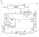
- FIG. 1 is an overall configuration diagram of a refrigeration cycle apparatus in which an outdoor unit according to the first embodiment of the present disclosure is used.
- the refrigeration cycle device 1 includes an outdoor unit 2 and a load unit 3.
- the load unit 3 is provided, for example, in a room.
- the outdoor unit 2 includes a refrigerant outlet port PO2 and a refrigerant inlet port PI2.
- the load unit 3 includes a refrigerant outlet port PO3 and a refrigerant inlet port PI3.
- the pipe 84 connects the refrigerant outlet port PO2 and the refrigerant inlet port PI3.
- the pipe 88 connects the refrigerant inlet port PI2 and the refrigerant outlet port PO3.
- the outdoor unit 2 includes a compressor 10, a condenser 20, a fan 22, and pipes 80, 81, 89.
- the load unit 3 includes an expansion valve 50, an evaporator 60, and pipes 85 to 87.
- the pipe 80 connects the discharge port G2 of the compressor 10 and the condenser 20.
- the pipe 81 connects the condenser 20 and the refrigerant outlet port PO2.
- the pipe 85 connects the refrigerant inlet port PI3 and the expansion valve 50.
- the pipe 86 connects the expansion valve 50 and the evaporator 60.
- the pipe 87 connects the evaporator 60 and the refrigerant outlet port PO3.
- the pipe 89 connects the refrigerant inlet port PI2 and the suction port G1 of the compressor 10.
- the compressor 10 compresses the refrigerant sucked from the suction port G1 and outputs it from the discharge port G2.
- the compressor 10 can adjust the rotation speed by changing the drive frequency by inverter control. By adjusting the rotation speed of the compressor 10, the circulation amount of the refrigerant can be adjusted, and the capacity of the refrigeration cycle device 1 can be adjusted.
- the compressor 10 includes an injection port G3, and the refrigerant sucked from the injection port G3 can flow into a portion in the middle of the compression process.
- Various types of compressors 10 can be adopted, and for example, scroll type, rotary type, screw type and the like can be adopted.
- the condenser 20 condenses the refrigerant discharged from the compressor 10 to the pipe 80 and outputs the refrigerant to the pipe 81.
- the condenser 20 is configured such that a high-temperature and high-pressure gas refrigerant discharged from the compressor 10 exchanges heat (heat dissipation) with the outside air. By this heat exchange, the refrigerant is condensed and changed to a liquid phase.
- the fan 22 supplies the condenser 20 with outside air through which the refrigerant exchanges heat in the condenser 20. By adjusting the rotation speed of the fan 22, the refrigerant pressure (high pressure side pressure) on the output side of the compressor 10 can be adjusted.
- the expansion valve 50 depressurizes the refrigerant output from the condenser 20 and flows into the pipe 85 through the refrigerant inlet port PI3, and outputs the refrigerant to the pipe 86.
- the expansion valve 50 is composed of, for example, an electronic linear expansion valve (LEV: Linear Expansion Valve).
- the evaporator 60 evaporates the refrigerant output from the expansion valve 50 to the pipe 86 and outputs the refrigerant to the pipe 87.
- the evaporator 60 is configured such that the refrigerant decompressed by the expansion valve 50 exchanges heat (endothermic) with the air in the load unit 3.
- the refrigerant evaporates as it passes through the evaporator 60 to become superheated steam. Then, the refrigerant output from the evaporator 60 to the pipe 87 is sucked into the compressor 10 through the refrigerant outlet port PO3, the refrigerant inlet port PI2, and the pipe 89.
- the compressor 10 is sucked from the discharge port G2 of the compressor 10 through the condenser 20, the refrigerant outlet port PO2 and the refrigerant inlet port PI3, the expansion valve 50, the evaporator 60, and the refrigerant outlet port PO3 and the refrigerant inlet port PI2.
- the refrigerant circulation flow path leading to the port G1 is referred to as a "main refrigerant circuit" of the refrigeration cycle device 1.
- the outdoor unit 2 further includes an expansion valve 70, a receiver 71, a flow rate adjusting valve 72, a throttle device 73, and pipes 91 to 95.
- the pipe 91 branches from the pipe 81 and is connected to the expansion valve 70.
- the pipe 92 connects the expansion valve 70 and the receiver 71.
- the pipe 93 connects the liquid refrigerant discharge port provided at the lower part (for example, the lower surface) of the receiver 71 to the flow rate adjusting valve 72.
- the pipe 94 connects the flow rate adjusting valve 72 and the injection port G3 of the compressor 10.
- the pipe 95 connects the gas refrigerant discharge port provided on the upper portion (for example, the upper surface) of the receiver 71 to the throttle device 73.
- the other end of the drawing device 73 is connected to the pipe 94.
- the expansion valve 70, the receiver 71, the flow rate adjusting valve 72, the throttle device 73, and the pipes 91 to 95 return a part of the refrigerant output from the condenser 20 to the compressor 10 without passing through the load unit 3. It constitutes an "injection circuit".
- the expansion valve 70 depressurizes the refrigerant flowing from the pipe 81 into the pipe 91 and outputs it to the receiver 71. Increasing the opening degree of the expansion valve 70 increases the amount of refrigerant flowing into the receiver 71. On the other hand, when the opening degree of the expansion valve 70 is reduced, the amount of refrigerant flowing into the receiver 71 is reduced.
- the expansion valve 70 is composed of, for example, a LEV.
- the receiver 71 is provided on the low pressure side of the expansion valve 70, and the refrigerant decompressed by passing through the expansion valve 70 is separated into two gas-liquid phases and accumulated. That is, in the receiver 71, the refrigerant is stored in a state of being separated into a liquid refrigerant and a gas refrigerant, and the liquid refrigerant is stored below the receiver 71.
- the pipe 93 is connected to a liquid refrigerant discharge port provided at the bottom of the receiver 71, and discharges the liquid refrigerant from the receiver 71.
- the flow rate adjusting valve 72 is provided in the pipe 93 and adjusts the amount of the liquid refrigerant discharged from the receiver 71 to the pipe 93.
- the flow rate regulating valve 72 is composed of, for example, a LEV.
- the pipe 95 is connected to a gas refrigerant discharge port provided above the receiver 71, and discharges the gas refrigerant from the receiver 71.
- the throttle device 73 is provided in the pipe 95 and adjusts the amount of gas refrigerant discharged from the receiver 71 to the pipe 95.
- the drawing device 73 is composed of, for example, a capillary tube. Then, the liquid refrigerant that has passed through the flow rate adjusting valve 72 and the gas refrigerant that has passed through the throttle device 73 merge at the pipe 94 and returned to the injection port G3 of the compressor 10.
- the injection port G3 may be provided in the suction chamber inside the shell of the compressor 10, or may be provided in the compression chamber inside the shell.
- a receiver 71 is provided in the injection circuit.
- the receiver can adjust the amount of refrigerant in the main refrigerant circuit according to the load fluctuation. Then, such a receiver can be provided on the high pressure side of the main refrigerant circuit.
- the refrigerant temperature in the receiver becomes the saturation temperature because the gas refrigerant is generally present in the receiver. Therefore, the degree of supercooling of the refrigerant cannot be ensured on the outlet side of the receiver, and a subcool heat exchange or the like must be separately provided on the outlet side of the receiver in order to secure the degree of supercooling.
- a supercritical refrigerant such as CO 2
- CO 2 When a supercritical refrigerant such as CO 2 is used, it is planned to be used in a supercritical state, and the supercritical refrigerant does not separate gas and liquid on the high pressure side. Therefore, the receiver provided on the high pressure side of the main refrigerant circuit cannot store the refrigerant in the supercritical state, and the amount of the refrigerant cannot be adjusted according to the load fluctuation.
- the receiver 71 is provided in the injection circuit and stores the refrigerant decompressed by the expansion valve 70.
- the degree of supercooling of the refrigerant can be ensured on the outlet side of the condenser 20 , and even when a supercritical refrigerant such as a CO 2 refrigerant is used, the refrigerant is stored in the receiver 71. be able to.
- the case of cooling a supercritical refrigerant such as CO 2 is also referred to as "condenser 20". Further, the amount of decrease of the refrigerant in the supercritical state from the reference temperature is also referred to as "supercooling degree”.
- the pressure on the outlet side (pressure on the high pressure side) of the compressor 10 may rise sharply due to the load fluctuation of the load unit 3.
- the pressure on the high pressure side rises excessively, it is required to quickly reduce the pressure while continuing the operation of the compressor 10.
- a supercritical refrigerant such as CO 2
- the refrigerant pressure is higher than that of CFCs, so prompt pressure suppression is required.
- control for promptly suppressing the high pressure side pressure is executed (hereinafter referred to as "pressure suppression control”). .).
- the opening degree of the expansion valve 70 is increased and the opening degree of the flow rate adjusting valve 72 is decreased.
- the opening degree of the expansion valve 70 increases, the amount of refrigerant flowing from the main refrigerant circuit into the receiver 71 increases.
- the opening degree of the flow rate adjusting valve 72 decreases, the gas flow rate ratio of the refrigerant returned from the receiver 71 to the compressor 10 increases, and the amount of liquid refrigerant carried out from the receiver 71 decreases.
- the outdoor unit 2 further includes a control device 100 that executes the above pressure suppression control. Further, the outdoor unit 2 further includes pressure sensors 110 and 111 and temperature sensors 120 and 121.
- the pressure sensor 110 detects the refrigerant pressure (low pressure side pressure) PL on the suction side of the compressor 10 and outputs the detected value to the control device 100.
- the pressure sensor 111 detects the refrigerant pressure (high pressure side pressure) PH on the discharge side of the compressor 10 and outputs the detected value to the control device 100.
- the temperature sensor 120 detects the temperature TH of the refrigerant discharged from the compressor 10 and outputs the detected value to the control device 100.
- the temperature sensor 121 detects the temperature T1 of the refrigerant on the outlet side of the condenser 20, and outputs the detected value to the control device 100.
- the control device 100 receives the detected values of the pressure sensors 110 and 111 and the temperature sensors 120 and 121, and executes control of each device in the outdoor unit 2 based on the detected values. Specifically, the control device 100 controls the operations of the compressor 10, the expansion valve 70, and the flow rate adjusting valve 72 based on the detected values of each sensor. Then, as the main control executed by the control device 100, the control device 100 executes a pressure suppression control for promptly suppressing the increased high pressure side pressure when the high pressure side pressure exceeds the threshold value.
- the pressure suppression control will be described in detail later.
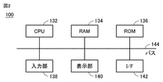
- FIG. 2 is a block diagram showing an example of the hardware configuration of the control device 100.
- the control device 100 includes a CPU (Central Processing Unit) 132, a RAM (Random Access Memory) 134, a ROM (Read Only Memory) 136, an input unit 138, a display unit 140, and I. / F portion 142 is included.
- the RAM 134, ROM 136, input unit 138, display unit 140, and I / F unit 142 are connected to the CPU 132 via the bus 144.
- the CPU 132 expands the program stored in the ROM 136 into the RAM 134 and executes it.
- the program stored in the ROM 136 is a program in which the processing procedure of the control device 100 is described.
- the outdoor unit 2 executes control of each device in the outdoor unit 2 according to these programs. Note that these controls are not limited to software processing, but can also be processed by dedicated hardware (electronic circuits).
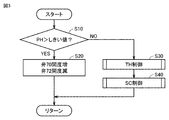
- FIG. 3 is a flowchart illustrating an example of a processing procedure of pressure suppression control executed by the control device 100. The series of processes shown in this flowchart are repeatedly executed while the outdoor unit 2 is operating.
- the control device 100 acquires the refrigerant pressure PH (high pressure side pressure) on the discharge side of the compressor 10 from the pressure sensor 111, and determines whether or not the pressure PH is higher than the threshold value. (Step S10).
- This threshold value is a value having an appropriate margin with respect to the high pressure protection set value for protecting the outdoor unit 2.
- the threshold value can be set to about 9 MPa with respect to the high pressure protection set value of about 10 MPa.
- the threshold value can be set to about 3.9 MPa with respect to the high pressure protection set value of 4.15 MPa.
- step S10 when it is determined in step S10 that the pressure PH is higher than the threshold value (YES in step S10), the control device 100 changes the opening degree of the expansion valve 70 of the injection circuit in the increasing direction and adjusts the flow rate.
- the opening degree of the valve 72 is changed in the decreasing direction (step S20).
- step S10 when it is determined in step S10 that the pressure PH is equal to or lower than the threshold value (NO in step S10), the control device 100 executes normal control. That is, the control device 100 executes TH control for adjusting the temperature TH of the refrigerant discharged from the compressor 10 to the target range (step S30), and controls the degree of supercooling SC of the refrigerant discharged from the condenser 20. SC control for adjusting to a target value (for example, about 5K) is executed (step S40). In this flowchart, it is assumed that the SC control is executed after the TH control is executed, but in reality, the TH control and the SC control can be executed in parallel or in parallel.
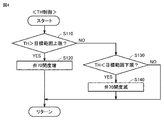
- FIG. 4 is a flowchart showing an example of the TH control processing procedure executed in step S30 of FIG.
- the control device 100 acquires the temperature TH of the refrigerant discharged from the compressor 10 from the temperature sensor 120, and determines whether or not the temperature TH is higher than the upper limit of the target range (step S110). ..
- the upper limit of this target range can be set to, for example, 100 ° C.
- the control device 100 changes the opening degree of the expansion valve 70 of the injection circuit in the increasing direction (step S120). As the opening degree of the expansion valve 70 increases, the amount of low-temperature refrigerant (injection amount) returned to the compressor 10 through the injection circuit increases, so that the temperature TH of the refrigerant on the outlet side of the compressor 10 can be lowered.
- step S110 determines whether or not the temperature TH is lower than the lower limit of the target range (step S130). ..
- the lower limit of this target range can be set to, for example, 70 ° C.
- the control device 100 changes the opening degree of the expansion valve 70 in the decreasing direction (step S140).
- the opening degree of the expansion valve 70 decreases, the injection amount decreases, so that the temperature TH of the refrigerant on the outlet side of the compressor 10 can be increased.
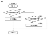
- FIG. 5 is a flowchart showing an example of the SC control processing procedure executed in step S40 of FIG.
- the control device 100 acquires the supercooling degree SC of the refrigerant on the outlet side of the condenser 20, and determines whether or not the supercooling degree SC is higher than the upper limit of the target range (step S210).
- the upper limit of the target range and the lower limit of the target range described later are upper and lower limit values appropriately set with respect to the control target value of the supercooling degree SC, and the control target value of the supercooling degree SC is set to, for example, 5K. ..
- the refrigerant pressure on the outlet side of the condenser 20 replaced by the pressure PH detected by the pressure sensor 111 is converted into the saturation temperature value of the refrigerant, and the temperature sensor 121 is obtained from this saturation temperature value. It can be calculated by subtracting the temperature T1 of the refrigerant on the outlet side of the condenser 20 detected by.
- the control device 100 changes the opening degree of the flow rate adjusting valve 72 of the injection circuit in the decreasing direction (step S220). ..
- the opening degree of the flow rate adjusting valve 72 decreases, the amount of liquid refrigerant carried out from the receiver 71 decreases. Therefore, the amount of liquid refrigerant stored in the receiver 71 increases, and the amount of refrigerant circulating in the main refrigerant circuit decreases. As a result, the temperature T1 of the refrigerant on the outlet side of the condenser 20 rises, and the supercooling degree SC decreases.
- step S210 determines whether or not the supercooling degree SC is lower than the target range lower limit.
- the control device 100 changes the opening degree of the flow rate adjusting valve 72 in the increasing direction (step S240).
- the opening degree of the flow rate adjusting valve 72 increases, the amount of liquid refrigerant carried out from the receiver 71 increases. Therefore, the amount of liquid refrigerant stored in the receiver 71 is reduced, and the amount of refrigerant circulating in the main refrigerant circuit is increased. As a result, the temperature T1 of the refrigerant on the outlet side of the condenser 20 decreases, and the supercooling degree SC increases.
- step S230 If it is determined in step S230 that the supercooling degree SC is equal to or higher than the lower limit of the target range (NO in step S230), the control device 100 shifts the process to return without executing step S240.
- the opening degree of the expansion valve 70 of the injection circuit is increased, so that the amount of refrigerant flowing into the receiver 71 increases. To do. Further, since the gas flow rate ratio of the refrigerant returned from the receiver 71 to the compressor 10 is increased, the amount of liquid refrigerant carried out from the receiver 71 is reduced. As a result, when the pressure PH exceeds the threshold value, the amount of liquid refrigerant stored in the receiver 71 is effectively increased, and the amount of refrigerant in the main refrigerant circuit is effectively reduced. Therefore, according to the first embodiment, the pressure increase on the high pressure side can be appropriately suppressed.
- the temperature TH on the outlet side of the compressor 10 is controlled within the target range, and the refrigerant on the outlet side of the condenser 20 is controlled.
- the supercooling degree SC is controlled to the target value. Therefore, according to the first embodiment, when the pressure PH is equal to or less than the threshold value, efficient operation can be performed by controlling the temperature TH and the supercooling degree SC as targets.
- a modified example of the first embodiment when the refrigerant pressure PH (high pressure side pressure) on the outlet side of the compressor 10 exceeds the threshold value, the opening degree of the expansion valve 70 is increased and the opening degree of the flow rate adjusting valve 72 is decreased. I decided to let you. As a result, the amount of liquid refrigerant stored in the receiver 71 can be increased and the amount of refrigerant circulating in the main refrigerant circuit can be reduced, and as a result, the pressure PH can be suppressed to the threshold value or lower.
- the refrigerant pressure PH high pressure side pressure
- the temperature TH of the refrigerant output from the compressor 10 may rise and exceed the upper limit threshold value. Therefore, in this modification, when the pressure PH exceeds the threshold value, that is, when the temperature TH exceeds the threshold value during the execution of the pressure suppression control, the opening degree change of the flow rate adjusting valve 72 ( (Decreasing direction) is stopped to maintain the opening degree of the flow rate adjusting valve 72. As a result, although it is not possible to reduce the temperature TH, it is possible to suppress the increase in the temperature TH.
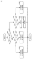
- FIG. 6 is a flowchart showing an example of a control processing procedure executed by the control device 100 in the modified example of the first embodiment. The series of processes shown in this flowchart are also repeatedly executed while the outdoor unit 2 is operating.
- the control device 100 acquires the pressure PH from the pressure sensor 111 and determines whether or not the pressure PH is higher than the threshold value (step S310). When it is determined that the pressure PH is higher than the threshold value (YES in step S310), the control device 100 acquires the temperature TH from the temperature sensor 120 and determines whether or not the temperature TH is higher than the threshold value. (Step S320).
- the control device 100 changes the opening degree of the expansion valve 70 of the injection circuit in the increasing direction and the flow rate as described in the first embodiment.
- the opening degree of the adjusting valve 72 is changed in the decreasing direction (step S330). As a result, the pressure PH can be quickly suppressed below the threshold value.
- step S320 when it is determined in step S320 that the temperature TH is higher than the threshold value (YES in step S320), the control device 100 changes the opening degree of the expansion valve 70 in the increasing direction and the flow rate adjusting valve 72. The change in opening degree (decrease direction) is stopped to maintain the opening degree of the flow rate adjusting valve 72 (step S340). As a result, it is possible to prevent the gas flow rate ratio of the refrigerant returned to the compressor 10 from further increasing, and to prevent the temperature TH from rising.
- step S310 determines whether or not the temperature TH is higher than the threshold value (step S310).
- This threshold value may be equal to the upper limit of the target range in TH control, or may be a set value higher than the upper limit of the target range.
- step S350 When it is determined in step S350 that the temperature TH is equal to or lower than the threshold value (NO in step S350), the control device 100 executes normal control. That is, the control device 100 executes TH control for adjusting the temperature TH to the target range (step S360), and also executes SC control for adjusting the supercooling degree SC to the target value (step S370).
- the TH control and the SC control are as described in the first embodiment.
- step S350 When it is determined in step S350 that the temperature TH is higher than the threshold value (YES in step S350), the control device 100 changes the opening degree of the expansion valve 70 in the increasing direction and opens the flow rate adjusting valve 72. Is also changed in the increasing direction (step S380).
- the opening degree of the expansion valve 70 increases, the amount of low-temperature refrigerant (injection amount) returned to the compressor 10 through the injection circuit increases, so that the temperature TH of the refrigerant output from the compressor 10 decreases.
- the opening degree of the flow rate adjusting valve 72 increases, the liquid flow rate ratio of the refrigerant returned to the compressor 10 increases, so that the temperature TH tends to decrease further.
- the opening degree of the flow rate adjusting valve 72 increases, the pressure PH tends to increase. However, in this case, since the pressure PH is below the threshold value (NO in step S310), the opening degree of the flow rate adjusting valve 72 is increased in order to lower the temperature TH unless the pressure PH exceeds the threshold value. Can be increased.
- the flow rate adjusting valve 72 is provided in the pipe 93 connected to the liquid refrigerant discharge port provided in the lower part of the receiver 71, and is provided in the gas refrigerant discharge port provided in the upper part of the receiver 71.
- the throttle device 73 is provided in the pipe 95 connected to the pipe 95.
- the flow rate adjusting valve is provided in the pipe 95, and the throttle device is provided in the pipe 93.
- FIG. 7 is an overall configuration diagram of a refrigeration cycle device in which the outdoor unit according to the second embodiment is used.
- the refrigeration cycle device 1A includes an outdoor unit 2A and a load unit 3.
- the outdoor unit 2A includes a flow rate adjusting valve 75 and a throttle device 76, respectively, in place of the flow rate adjusting valve 72 and the throttle device 73 in the configuration of the outdoor unit 2 according to the first embodiment shown in FIG. Instead, the control device 100A is included.
- the flow rate adjusting valve 75 is provided in the pipe 95 connected to the gas refrigerant discharge port provided on the upper part (for example, the upper surface) of the receiver 71, and adjusts the amount of the gas refrigerant discharged from the receiver 71 to the pipe 95.
- the throttle device 76 is provided in a pipe 93 connected to a liquid refrigerant discharge port provided in the lower part (for example, the lower surface) of the receiver 71, and decompresses the liquid refrigerant discharged from the receiver 71 to the pipe 93 and outputs the pressure to the pipe 94. ..
- control device 100A Similar to the control device 100 in the first embodiment, the control device 100A also quickly suppresses the increased pressure PH when the refrigerant pressure PH (high pressure side pressure) on the discharge side of the compressor 10 exceeds the threshold value. Perform pressure suppression control for.
- the hardware configuration of the control device 100A is the same as the configuration shown in FIG.
- FIG. 8 is a flowchart illustrating an example of a processing procedure of pressure suppression control executed by the control device 100A in the second embodiment. This flowchart corresponds to the flowchart shown in FIG. The series of processes shown in this flowchart are also repeatedly executed while the outdoor unit 2A is operating.
- the control device 100A acquires the detected value of the pressure PH from the pressure sensor 111, and determines whether or not the pressure PH is higher than the threshold value (step S410).
- the threshold value is the same as the threshold value used in step S10 of FIG.
- step S410 when it is determined in step S410 that the pressure PH is higher than the threshold value (YES in step S410), the control device 100A changes the opening degree of the expansion valve 70 of the injection circuit in the increasing direction and adjusts the flow rate.
- the opening degree of the valve 75 is changed in the increasing direction (step S420).
- the opening degree of the flow rate adjusting valve 75 increases, the gas flow rate ratio of the refrigerant returned from the receiver 71 to the compressor 10 increases, and the amount of liquid refrigerant carried out from the receiver 71 decreases.
- the pressure PH exceeds the threshold value, the amount of liquid refrigerant stored in the receiver 71 increases, and the amount of refrigerant circulating in the main refrigerant circuit decreases.
- the increase in pressure PH can be effectively suppressed.
- step S410 when it is determined in step S410 that the pressure PH is equal to or lower than the threshold value (NO in step S410), the control device 100A executes normal control. That is, the control device 100A executes TH control for adjusting the temperature TH to the target range (step S430), and also executes SC control for adjusting the supercooling degree SC to the target value (step S440).
- the TH control and the SC control are as described in the first embodiment.
- a modified example of the second embodiment is also in the second embodiment, as in the modification of the first embodiment, when the pressure PH exceeds the threshold value, that is, when the temperature TH exceeds the threshold value during the execution of the pressure suppression control. Stops the change in opening degree (increase direction) of the flow rate adjusting valve 75 to maintain the opening degree of the flow rate adjusting valve 75. As a result, although it is not possible to reduce the temperature TH, it is possible to suppress the increase in the temperature TH.
- FIG. 9 is a flowchart showing an example of a control processing procedure executed by the control device 100A in the modified example of the second embodiment. The series of processes shown in this flowchart are also repeatedly executed while the outdoor unit 2A is operating.
- the control device 100A acquires the pressure PH from the pressure sensor 111 and determines whether or not the pressure PH is higher than the threshold value (step S510).
- the control device 100A acquires the temperature TH from the temperature sensor 120 and determines whether or not the temperature TH is higher than the threshold value. (Step S520).
- the control device 100A changes the opening degree of the expansion valve 70 of the injection circuit in the increasing direction and the flow rate as described in the second embodiment.
- the opening degree of the adjusting valve 75 is changed in the increasing direction (step S530). As a result, the pressure PH can be quickly suppressed below the threshold value.
- step S520 When it is determined in step S520 that the temperature TH is higher than the threshold value (YES in step S520), the control device 100A changes the opening degree of the expansion valve 70 in the increasing direction and opens the flow rate adjusting valve 75. The change (increase direction) is stopped to maintain the opening degree of the flow rate adjusting valve 75 (step S540). As a result, it is possible to prevent the gas flow rate ratio of the refrigerant returned to the compressor 10 from further increasing, and to prevent the temperature TH from rising.
- step S510 determines whether or not the pressure PH is equal to or lower than the threshold value (NO in step S510). S550). When it is determined that the temperature TH is below the threshold value (NO in step S550), the control device 100A executes normal control. That is, the control device 100A executes TH control for adjusting the temperature TH to the target range (step S560), and also executes SC control for adjusting the supercooling degree SC to the target value (step S570).
- the TH control and the SC control are as described in the first embodiment.
- step S550 When it is determined in step S550 that the temperature TH is higher than the threshold value (YES in step S550), the control device 100A changes the opening degree of the expansion valve 70 in the increasing direction and opens the flow rate adjusting valve 75. Is changed in the decreasing direction (step S580).
- the opening degree of the expansion valve 70 increases, the amount of low-temperature refrigerant (injection amount) returned to the compressor 10 through the injection circuit increases, so that the temperature TH of the refrigerant output from the compressor 10 decreases.
- the opening degree of the flow rate adjusting valve 75 decreases, the gas flow rate ratio of the refrigerant returned to the compressor 10 decreases and the liquid flow rate ratio increases, so that the temperature TH tends to decrease further.
- the opening degree of the flow rate adjusting valve 75 decreases, the pressure PH tends to increase. However, in this case, since the pressure PH is below the threshold value (NO in step S510), the opening degree of the flow rate adjusting valve 75 is increased in order to lower the temperature TH unless the pressure PH exceeds the threshold value. Can be reduced.
- the refrigerant flowing through the injection circuit is returned to the injection port G3 of the compressor 10, but is returned to the pipe 89 on the suction side of the compressor 10. It may be.
- the throttle devices 73 and 76 are configured by the capillary tube, but a flow rate adjusting valve such as LEV may be used instead of the capillary tube.
- the pipe 95 is connected to the upper part of the receiver 71 and the throttle device 73 is provided in the pipe 95, but the pipe 95 and the throttle device 73 are not provided. There may be. Alternatively, the piping 95 may not be provided with the throttle device 73.
- the outdoor unit and the refrigeration cycle device mainly used for warehouses, showcases, etc. have been typically described, but the outdoor unit according to the present disclosure uses a refrigeration cycle. It can also be applied to air conditioners.
- 1,1A refrigeration cycle device 1,2A outdoor unit, 3 load unit, 10 compressor, 20 condenser, 22 fan, 50, 70 expansion valve, 60 evaporator, 71 receiver, 72,75 flow control valve, 73, 76 squeezing device, 80-95 piping, 100, 100A control device, 110, 111 pressure sensor, 120, 121 temperature sensor, 132 CPU, 134 RAM, 136 ROM, 138 input section, 140 display section, 142 I / F section, 144 Bus, G1 suction port, G2 discharge port, G3 injection port, PI2, PI3 refrigerant inlet port, PO2, PO3 refrigerant outlet port.
Landscapes
- Engineering & Computer Science (AREA)
- Physics & Mathematics (AREA)
- Mechanical Engineering (AREA)
- Thermal Sciences (AREA)
- General Engineering & Computer Science (AREA)
- Air Conditioning Control Device (AREA)
Priority Applications (7)
| Application Number | Priority Date | Filing Date | Title |
|---|---|---|---|
| PCT/JP2019/035371 WO2021048899A1 (ja) | 2019-09-09 | 2019-09-09 | 室外ユニット及び冷凍サイクル装置 |
| CN201980099966.6A CN114341568B (zh) | 2019-09-09 | 2019-09-09 | 室外单元以及制冷循环装置 |
| JP2021544988A JP7154426B2 (ja) | 2019-09-09 | 2019-09-09 | 室外ユニット及び冷凍サイクル装置 |
| EP19944675.8A EP4030115B1 (en) | 2019-09-09 | 2019-09-09 | Outdoor unit and refrigeration cycle device |
| FIEP19944675.8T FI4030115T3 (fi) | 2019-09-09 | 2019-09-09 | Ulkoyksikkö ja jäähdytyskiertolaite |
| ES19944675T ES2964740T3 (es) | 2019-09-09 | 2019-09-09 | Unidad de exterior y dispositivo de ciclo de refrigeración |
| DK19944675.8T DK4030115T3 (da) | 2019-09-09 | 2019-09-09 | Udendørsenhed og kølekredsløbsindretning |
Applications Claiming Priority (1)
| Application Number | Priority Date | Filing Date | Title |
|---|---|---|---|
| PCT/JP2019/035371 WO2021048899A1 (ja) | 2019-09-09 | 2019-09-09 | 室外ユニット及び冷凍サイクル装置 |
Publications (1)
| Publication Number | Publication Date |
|---|---|
| WO2021048899A1 true WO2021048899A1 (ja) | 2021-03-18 |
Family
ID=74866215
Family Applications (1)
| Application Number | Title | Priority Date | Filing Date |
|---|---|---|---|
| PCT/JP2019/035371 Ceased WO2021048899A1 (ja) | 2019-09-09 | 2019-09-09 | 室外ユニット及び冷凍サイクル装置 |
Country Status (7)
| Country | Link |
|---|---|
| EP (1) | EP4030115B1 (enExample) |
| JP (1) | JP7154426B2 (enExample) |
| CN (1) | CN114341568B (enExample) |
| DK (1) | DK4030115T3 (enExample) |
| ES (1) | ES2964740T3 (enExample) |
| FI (1) | FI4030115T3 (enExample) |
| WO (1) | WO2021048899A1 (enExample) |
Cited By (2)
| Publication number | Priority date | Publication date | Assignee | Title |
|---|---|---|---|---|
| JPWO2022249289A1 (enExample) * | 2021-05-25 | 2022-12-01 | ||
| JPWO2022249288A1 (enExample) * | 2021-05-25 | 2022-12-01 |
Citations (5)
| Publication number | Priority date | Publication date | Assignee | Title |
|---|---|---|---|---|
| JPS5668755A (en) * | 1979-11-07 | 1981-06-09 | Mitsubishi Heavy Ind Ltd | Refrigerating cycle |
| JPS59157446A (ja) * | 1983-02-22 | 1984-09-06 | 松下電器産業株式会社 | 冷凍サイクル装置 |
| JPS59175961U (ja) | 1983-05-13 | 1984-11-24 | 株式会社東芝 | 空気調和機 |
| JP2010127531A (ja) * | 2008-11-27 | 2010-06-10 | Mitsubishi Electric Corp | 冷凍空調装置 |
| WO2016051493A1 (ja) * | 2014-09-30 | 2016-04-07 | 三菱電機株式会社 | 冷凍サイクル装置 |
Family Cites Families (10)
| Publication number | Priority date | Publication date | Assignee | Title |
|---|---|---|---|---|
| JPS6490961A (en) * | 1987-09-30 | 1989-04-10 | Daikin Ind Ltd | Refrigeration circuit |
| JP3623090B2 (ja) * | 1997-11-20 | 2005-02-23 | 松下電器産業株式会社 | インジェクション機能を有する冷凍サイクルの制御装置 |
| JP2006170500A (ja) * | 2004-12-14 | 2006-06-29 | Mitsubishi Heavy Ind Ltd | 空気調和装置およびその運転方法 |
| CN200996753Y (zh) * | 2006-12-26 | 2007-12-26 | 海信集团有限公司 | 带经济器的中间补气压缩机制冷系统 |
| US9951974B2 (en) * | 2008-09-29 | 2018-04-24 | Carrier Corporation | Flash tank economizer cycle control |
| WO2011112411A1 (en) * | 2010-03-08 | 2011-09-15 | Carrier Corporation | Defrost operations and apparatus for a transport refrigeration system |
| CN102859295B (zh) * | 2010-04-28 | 2014-08-20 | 松下电器产业株式会社 | 制冷循环装置 |
| CN106766293B (zh) * | 2016-12-02 | 2019-11-19 | 珠海格力电器股份有限公司 | 一种防止冷媒回流的补气增焓空调系统及其控制方法 |
| US10345038B2 (en) * | 2017-04-25 | 2019-07-09 | Emerson Climate Technologies Retail Solutions, Inc. | Dynamic coefficient of performance calculation for refrigeration systems |
| CN111023605A (zh) * | 2019-12-20 | 2020-04-17 | 北京工业大学 | 一种高压比制冷压缩机分流气液共进补气口协同降温方法 |
-
2019
- 2019-09-09 WO PCT/JP2019/035371 patent/WO2021048899A1/ja not_active Ceased
- 2019-09-09 FI FIEP19944675.8T patent/FI4030115T3/fi active
- 2019-09-09 ES ES19944675T patent/ES2964740T3/es active Active
- 2019-09-09 EP EP19944675.8A patent/EP4030115B1/en active Active
- 2019-09-09 DK DK19944675.8T patent/DK4030115T3/da active
- 2019-09-09 CN CN201980099966.6A patent/CN114341568B/zh not_active Expired - Fee Related
- 2019-09-09 JP JP2021544988A patent/JP7154426B2/ja active Active
Patent Citations (5)
| Publication number | Priority date | Publication date | Assignee | Title |
|---|---|---|---|---|
| JPS5668755A (en) * | 1979-11-07 | 1981-06-09 | Mitsubishi Heavy Ind Ltd | Refrigerating cycle |
| JPS59157446A (ja) * | 1983-02-22 | 1984-09-06 | 松下電器産業株式会社 | 冷凍サイクル装置 |
| JPS59175961U (ja) | 1983-05-13 | 1984-11-24 | 株式会社東芝 | 空気調和機 |
| JP2010127531A (ja) * | 2008-11-27 | 2010-06-10 | Mitsubishi Electric Corp | 冷凍空調装置 |
| WO2016051493A1 (ja) * | 2014-09-30 | 2016-04-07 | 三菱電機株式会社 | 冷凍サイクル装置 |
Cited By (7)
| Publication number | Priority date | Publication date | Assignee | Title |
|---|---|---|---|---|
| JPWO2022249289A1 (enExample) * | 2021-05-25 | 2022-12-01 | ||
| WO2022249289A1 (ja) * | 2021-05-25 | 2022-12-01 | 三菱電機株式会社 | 冷凍サイクル装置 |
| JPWO2022249288A1 (enExample) * | 2021-05-25 | 2022-12-01 | ||
| WO2022249288A1 (ja) * | 2021-05-25 | 2022-12-01 | 三菱電機株式会社 | 冷凍サイクル装置 |
| JP7466771B2 (ja) | 2021-05-25 | 2024-04-12 | 三菱電機株式会社 | 冷凍サイクル装置 |
| EP4350246A4 (en) * | 2021-05-25 | 2024-07-10 | Mitsubishi Electric Corporation | REFRIGERATION CYCLE DEVICE |
| EP4350247A4 (en) * | 2021-05-25 | 2024-08-14 | Mitsubishi Electric Corporation | REFRIGERATION CYCLE DEVICE |
Also Published As
| Publication number | Publication date |
|---|---|
| CN114341568B (zh) | 2023-07-18 |
| JP7154426B2 (ja) | 2022-10-17 |
| ES2964740T3 (es) | 2024-04-09 |
| JPWO2021048899A1 (enExample) | 2021-03-18 |
| FI4030115T3 (fi) | 2023-11-20 |
| EP4030115A1 (en) | 2022-07-20 |
| EP4030115A4 (en) | 2022-09-07 |
| EP4030115B1 (en) | 2023-10-25 |
| CN114341568A (zh) | 2022-04-12 |
| DK4030115T3 (da) | 2023-11-27 |
Similar Documents
| Publication | Publication Date | Title |
|---|---|---|
| KR100922222B1 (ko) | 공기조화 시스템 | |
| US10527330B2 (en) | Refrigeration cycle device | |
| JP7150148B2 (ja) | 室外ユニット、冷凍サイクル装置および冷凍機 | |
| JP7224480B2 (ja) | 室外ユニットおよび冷凍サイクル装置 | |
| CN102538298B (zh) | 热泵及其控制方法 | |
| JP7282258B2 (ja) | 室外ユニットおよび冷凍サイクル装置 | |
| JP7154426B2 (ja) | 室外ユニット及び冷凍サイクル装置 | |
| JP7378561B2 (ja) | 室外ユニットおよび冷凍サイクル装置 | |
| JP7195449B2 (ja) | 室外ユニットおよび冷凍サイクル装置 | |
| KR101450543B1 (ko) | 공기조화 시스템 | |
| KR20090074437A (ko) | 공기조화 시스템 | |
| JPWO2015132951A1 (ja) | 冷凍装置 | |
| CN113302436A (zh) | 空气调节装置 | |
| WO2015121992A1 (ja) | 冷凍サイクル装置 | |
| WO2025027752A1 (ja) | 冷凍サイクル装置 | |
| JP2009236430A (ja) | 圧縮式冷凍機及びその容量制御方法 | |
| JP7450772B2 (ja) | 冷凍サイクル装置 | |
| WO2021205540A1 (ja) | 冷凍サイクル装置 | |
| WO2024023993A1 (ja) | 冷凍サイクル装置 | |
| WO2024009351A1 (ja) | 冷凍サイクル装置 | |
| WO2024201592A1 (ja) | 冷凍サイクル装置 | |
| WO2023100233A1 (ja) | 空気調和装置 | |
| KR20090068969A (ko) | 공기조화 시스템 |
Legal Events
| Date | Code | Title | Description |
|---|---|---|---|
| 121 | Ep: the epo has been informed by wipo that ep was designated in this application |
Ref document number: 19944675 Country of ref document: EP Kind code of ref document: A1 |
|
| ENP | Entry into the national phase |
Ref document number: 2021544988 Country of ref document: JP Kind code of ref document: A |
|
| NENP | Non-entry into the national phase |
Ref country code: DE |
|
| ENP | Entry into the national phase |
Ref document number: 2019944675 Country of ref document: EP Effective date: 20220411 |