WO2021044530A1 - サンバイザホルダ - Google Patents
サンバイザホルダ Download PDFInfo
- Publication number
- WO2021044530A1 WO2021044530A1 PCT/JP2019/034663 JP2019034663W WO2021044530A1 WO 2021044530 A1 WO2021044530 A1 WO 2021044530A1 JP 2019034663 W JP2019034663 W JP 2019034663W WO 2021044530 A1 WO2021044530 A1 WO 2021044530A1
- Authority
- WO
- WIPO (PCT)
- Prior art keywords
- wall
- engaging piece
- sun visor
- mounting hole
- wall portion
- Prior art date
- Legal status (The legal status is an assumption and is not a legal conclusion. Google has not performed a legal analysis and makes no representation as to the accuracy of the status listed.)
- Ceased
Links
Images






Classifications
-
- B—PERFORMING OPERATIONS; TRANSPORTING
- B60—VEHICLES IN GENERAL
- B60J—WINDOWS, WINDSCREENS, NON-FIXED ROOFS, DOORS, OR SIMILAR DEVICES FOR VEHICLES; REMOVABLE EXTERNAL PROTECTIVE COVERINGS SPECIALLY ADAPTED FOR VEHICLES
- B60J3/00—Antiglare equipment associated with windows or windscreens; Sun visors for vehicles
- B60J3/02—Antiglare equipment associated with windows or windscreens; Sun visors for vehicles adjustable in position
- B60J3/0204—Sun visors
- B60J3/0213—Sun visors characterised by the mounting means
-
- B—PERFORMING OPERATIONS; TRANSPORTING
- B60—VEHICLES IN GENERAL
- B60J—WINDOWS, WINDSCREENS, NON-FIXED ROOFS, DOORS, OR SIMILAR DEVICES FOR VEHICLES; REMOVABLE EXTERNAL PROTECTIVE COVERINGS SPECIALLY ADAPTED FOR VEHICLES
- B60J3/00—Antiglare equipment associated with windows or windscreens; Sun visors for vehicles
- B60J3/02—Antiglare equipment associated with windows or windscreens; Sun visors for vehicles adjustable in position
- B60J3/0204—Sun visors
- B60J3/0213—Sun visors characterised by the mounting means
- B60J3/023—Additional support bracket releasably holding the sun visor
Definitions
- the present invention relates to a sun visor holder that is mounted in a mounting hole.
- the vehicle is equipped with a sun visor to protect the eyes of the occupants from sunlight and the like.
- a sun visor to protect the eyes of the occupants from sunlight and the like.
- shafts protruding from both ends in the longitudinal direction are rotatably held by a sun visor holder attached to the inner wall of the vehicle, and are rotated during use so as to be placed in front of the occupant's field of vision. ing.
- the following Patent Document 1 includes a main body portion and a leg portion inserted into and fixed to a mounting hole, and the main body portion includes a base portion and a base portion.
- the first engaging piece which has a holding portion for attaching and detaching the shaft and an insertion portion for receiving the shaft, and the leg portion is arranged on the side opposite to the insertion portion of the main body portion and engages with the mounting hole. It has a pair of second engaging pieces that engage with the mounting hole in cooperation with the first engaging piece, and the first engaging piece can bend inward with the tip end side of the leg as a fulcrum.
- a sun visor holder that is formed and has a release portion that extends outward from its free end side.
- the release portion When removing the above sun visor holder from the mounting hole, first, the release portion is pressed to bend the first engaging piece inward to release the engagement with the mounting hole, and then the mounting hole and the second.
- the sun visor holder can be removed from the mounting hole by disengaging it from the engaging piece.
- an object of the present invention is to provide a sun visor holder that can be easily removed from the mounting hole.
- the present invention is a sun visor holder that is attached to a mounting hole and holds the shaft of the sun visor detachably, and is inserted into a base portion having a holding portion for holding the shaft and the mounting hole. It has a leg portion to be fixed, and the leg portion has a first wall portion and a second wall portion which are erected from the base portion and arranged to face each other, and the first wall portion is provided.
- the wall portion has a first engaging piece that is flexibly and deformably formed through a slit and engages with the mounting hole, and the first engaging piece has the first engaging piece and the mounting.
- a release portion that enables disengagement with the hole is provided, and the base end portion of the second wall portion is connected to the tip end side of the second wall portion in the erection direction and is bent.
- a pair of second engaging pieces that are deformable and engage with the mounting holes and a vertical wall that is arranged between the pair of second engaging pieces and extends in the vertical direction of the second wall portion are provided.
- a groove portion extending in the erection direction of the second wall portion and thinning the second wall portion is formed between each second engaging piece and the standing wall of the second wall portion. It is characterized by being done.
- the release portion when removing the sun visor holder from the mounting hole, the release portion is pushed in to disengage the first engaging piece from the mounting hole, and then the leg portion is gradually pulled out from the mounting hole. , The engagement with the mounting hole is released while bending and deforming the pair of second engaging pieces.
- the pair of second engaging pieces can be easily bent and deformed in the direction approaching the second wall portion. It is possible to easily disengage the pair of second engaging pieces from the mounting holes, and it is easy to remove the sun visor holder from the mounting holes, because it can be easily bent and deformed in the direction approaching each other. ..
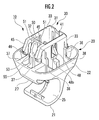
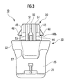
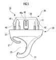
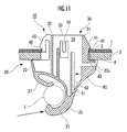
- FIG. 1 It is a perspective view which shows one Embodiment of the sun visor holder which concerns on this invention. It is an enlarged perspective view of the sun visor holder. It is a front view of the sun visor holder. It is a top view of the sun visor holder. It is a right side view of the sun visor holder. It is a rear view of the sun visor holder. It is a top view of the sun visor holder in a state where a part is broken. It is sectional drawing of the state in which the sun visor holder is attached to the attachment hole. It is a top view of the state in which the sun visor holder is attached to the attachment hole.
- FIG. 5 is a plan view showing the action of the stopper wall when the first engaging piece is bent and deformed when the sun visor holder is removed from the mounting hole.
- the sun visor holder 10 of this embodiment is attached to the inner wall of the vehicle through a rectangular mounting hole 2 formed in the vehicle panel 1, and a shaft protruding from both ends in the longitudinal direction of the sun visor (not shown). 5 is for detachably rotating and holding.
- Trim members 3 are arranged on the front side of the vehicle panel 1 in an overlapping manner.
- the trim member 3 is formed with a rectangular insertion hole 4 that is larger than the mounting hole 2 of the vehicle panel 1.
- the sun visor holder 10 in this embodiment has a base portion 20 having a holding portion 21 that detachably holds the shaft 5 of the sun visor, and a leg portion 30 that is inserted into and fixed to the mounting hole 2. And have.
- the base portion 20 has a peripheral wall 22 and a bottom portion 23 (see FIG. 4), has a bottomed frame shape that extends long in one direction, and is arranged in contact with the front side of the trim member 3. (See FIG. 8). As shown in FIG. 6, a substantially U-shaped notch 22a is formed at one end of the base portion 20 in the longitudinal direction.
- the direction along the longitudinal direction of the base portion 20 is defined as the longitudinal direction A, and the direction orthogonal to the longitudinal direction A of the base portion 20 is defined as the width direction B. explain.
- the holding portion 21 extends from a portion of the base portion 20 near one end in the longitudinal direction A so as to form a substantially C shape, and the shaft 5 of the sun visor can be attached and detached. Hold. Inside the holding portion 21, an insertion portion 25 for receiving the shaft 5 of the sun visor is provided.
- a pressing piece 27 extends from the other end side of the base portion 20 in the longitudinal direction A so as to form a curved shape toward the insertion portion 25, and the pressing piece 27 extends. However, it elastically abuts on the outer circumference of the shaft 5 of the sun visor to prevent it from coming off and to suppress the rattling (see FIG. 8).
- the leg portion 30 has a first wall portion 31 and a second wall portion 32 that are erected from the base portion 20 and are arranged so as to face each other.
- the leg portion 30 in this embodiment is arranged on one end side of the base portion 20 in the longitudinal direction A, and the first wall portion 31 extends along the width direction B of the base portion 20.
- a second wall portion 32 that is arranged on the other end side of the base portion 20 in the longitudinal direction A and extends along the width direction B of the base portion 20, and both wall portions 31 and 32 are parallel to each other. Is located in.
- the leg portion 30 has a pair of side wall portions 33, 33 that connect the opposite end portions of the wall portions 31, 32 to each other.
- the wall portions 31, 32, 33, 33 are erected from the bottom portion 23 of the base portion 20 (see FIG. 8).
- the leg portion 30 has a substantially rectangular frame shape in which the tip end side in the erection direction is opened and the internal space 34 is provided inside.
- the base end side of the first wall portion 31 and the peripheral wall 22 of the base portion 20 are connected by connecting portions 36, 36, and are connected to the base end portion side of the second wall portion 32.
- the peripheral wall 22 of the base portion 20 are connected by connecting portions 37, 37, and the base end portion side of each side wall portion 33 and the peripheral wall 22 of the base portion 20 are connected by connecting portions 38, 38. The rigidity of the leg portion 30 is maintained.
- first wall portion 31 has a first engaging piece 41 that is flexibly and deformably formed through a slit 41a and engages with the mounting hole 2, and the first engaging piece 41 has a first engaging piece 41. 1
- a release portion 43 is provided so that the engagement piece 41 and the mounting hole 2 can be disengaged.
- the first wall portion 31 is formed with a substantially U-shaped slit 41a that communicates with the notch portion 22a of the base portion 20.
- the first engaging piece 41 is provided so as to be flexible via the 41a.
- the base end portion of the first engaging piece 41 is connected to the tip end portion side of the first wall portion 31 in the erection direction, and the first engaging piece 41 can be flexed and deformed in a direction in which the first wall portion 31 is close to and separated from the second wall portion 32. (See FIGS. 8 and 12).
- the outer surface of the first engaging piece 41 on the base end portion side forms an inclined surface that gradually protrudes outward as it approaches the base portion 20, and the height of the first engaging piece 41 gradually decreases from the most protruding portion.
- An engaging portion 42 inclined as described above is formed, and this engaging portion 42 is a portion that engages with the back peripheral edge of the mounting hole 2 (see FIG. 8).
- a release portion 43 extends toward the free end portion of the first engaging piece 41 opposite to the base end portion toward the side opposite to the second wall portion 32. ing.
- the release portion 43 is arranged in the notch portion 22a of the peripheral wall 22 of the base portion 20 so as not to protrude from the outer peripheral surface of the base portion 20 (see FIGS. 6 and 8). Therefore, the release portion 43 has a structure that makes it difficult to push the release portion 43 from the outside of the base portion 20 with a finger or the like.
- a push tool 7 such as a flat-blade screwdriver is used. It will be pushed in.
- the releasing portion 43 is pressed from the front side of the trim member 3 to the second wall by the pushing tool 7.
- the first engaging piece 41 bends and deforms while moving in the internal space 34 of the leg portion 30 via the releasing portion 43, and the engaging portion is deformed.
- the 42 is disengaged from the back peripheral edge of the mounting hole 2 so that the first engaging piece 41 is disengaged from the mounting hole 2.
- the base end portion of the second wall portion 32 is connected to the tip end side of the second wall portion 32 in the vertical direction, and is made flexible and deformable, so that the mounting hole 2 has a base end portion.
- a pair of second engaging pieces 45, 45 to be engaged and a standing wall 50 arranged between the pair of second engaging pieces 45, 45 and extending in the vertical direction of the second wall portion are provided.
- the base end portion of the second engaging piece 45 is the outer surface side of the second wall portion 32 and is connected to the tip end side in the erection direction. It extends diagonally outward toward the base 20 side.
- the "outer surface side" of the second wall portion 32 means the side of the second wall portion 32 opposite to the surface facing the first wall portion 31.
- an engaging portion 46 that engages with the back peripheral edge of the mounting hole 2 is provided on the outer surface of each second engaging piece 45 on the free end side opposite to the base end portion (see FIG. 8). ).
- the pair of side wall portions 33, 33 constituting the leg portion 30 have a substantially U-shape at a position closer to the second wall portion 32.
- a slit 48a is formed, and through the slit 48a, temporary holding pieces 48, 48 having a substantially triangular plate shape that can be bent toward the internal space 34 of the leg portion 30 are provided, respectively.
- An engaging portion 48b is provided at one end of each temporary holding piece 48.
- each temporary holding piece 48 engages with the back peripheral edge of the insertion hole 4 of the trim member 3, and the base portion 20 comes into contact with the front peripheral edge of the insertion hole 4, so that the trim member 3 is engaged.
- the sun visor holder 10 is temporarily held.
- the vertical wall 50 in this embodiment has a substantially elongated plate shape in which the outer surface of the tip is cut in a tapered shape, and has a length extending from the bottom 23 of the base portion 20 to the tip of the second wall portion 32 in the vertical direction. It is extending.
- a groove portion 51 extending in the vertical direction of the second wall portion 32 and thinning the second wall portion 32 is formed. Has been done.
- the groove portion 51 in this embodiment has a substantially U-shaped groove shape, is the outer surface side of the second wall portion 32, and is the second engaging piece 45. It is arranged on the inner edge of the base end portion of the base portion 20 and extends to the bottom portion 23 of the base portion 20 respectively. Further, as shown in FIG. 7, the width W1 of the groove 51 (direction along the width direction B) is narrower than the distance W2 (direction along the width direction B) between the standing wall 50 and the second engaging piece 45. It is formed.
- the base end portion of the second engaging piece 45 and the side portion of the second wall portion 32 in the width direction B are connected.
- the thickness T2 of the portion 44 is formed to be thicker than the thickness T1 of the portion forming the groove portion 51 of the second wall portion 32.
- the connecting portion 44 is wider than the groove portion 51 (the direction along the width direction B is larger) and has a substantially square columnar shape (see FIG. 7).
- the groove portion 51 by providing the groove portion 51, the sun visor holder 10 is attached to the attachment hole 2, and after the engagement between the first engaging piece 41 and the attachment hole 2 is released, the leg portion is provided from the attachment hole 2.
- the leg portion 30 is gradually pulled out from the mounting hole 2 in order to remove the 30 (a mode in which a pulling load is slowly applied to the second engaging piece 45)
- the second engaging piece 45 is easily bent and deformed. ..
- a sudden force such as an impact force is applied from the outside in a state where the sun visor holder 10 is attached to the attachment hole 2
- a sudden pull-out load is applied to the second engaging piece 45.
- the second engaging piece 45 is intentionally easily damaged.
- the groove 51 may have a substantially U-shape, a substantially V-shape, or the like, and is not particularly limited.
- the position of forming the groove is also not particularly limited, but it is preferably arranged along the inner edge of the second engaging piece 45 on the base end side.
- the range of forming the groove (the range along the vertical direction of the vertical wall) is not particularly limited, but is preferably in the range where the base end portion of the second engaging piece 45 is provided.
- a wide portion 53 is provided on the base end side of the vertical wall 50 so as to be able to come into contact with the inner circumference of the mounting hole 2 (see FIG. 9).
- the wide portion 53 in this embodiment is the tip side of the vertical wall 50 in the protruding direction from the second wall portion 32 (the position farthest from the outer surface of the second wall portion 32 in a plan view as shown in FIG. 7). Moreover, as shown in FIGS. 2 and 3, on the base end side in the erection direction, the shape is ribbed toward the pair of second engaging pieces 45, 45. As a result, as shown in FIGS. 2 and 3, the width of the wide portion 53 on the tip end side (length along the width direction B) of the vertical wall 50 in the erection direction is wide. Further, the wide portion 53 extends from the bottom portion 23 of the base portion 20.
- the base end portion side of the standing wall 50 and the peripheral wall 22 of the base portion 20 are connected by a connecting portion 55, and the rigidity of the standing wall 50 is maintained. ..
- ribs are provided at positions on the inner surface side (opposing surface side) of the pair of side wall portions 33, 33 constituting the leg portion 30 and close to the second wall portion 32. 57 and 57 are erected respectively. These ribs 57, 57 improve the rigidity and impact resistance of the pair of side wall portions 33, 33.
- a stopper wall 60 is provided to regulate the bending deformation of the second engaging piece 45 toward the first wall portion 31 side. Further, the stopper wall 60 guides the first engaging piece 41 to the center of the stopper wall 60 as shown in FIG. 13 when the first engaging piece 41 is bent and deformed toward the second wall portion 32 side.
- a concave receiving portion 65 having tapered surfaces on both sides is provided.
- FIG. 7 shows the inner surface side (opposing surface side) of the pair of side wall portions 33, 33, which are close to the first wall portion 31, are connected by the stopper wall 60. ..
- FIG. 8 shows the rotation locus K of the first engaging piece 41, but the stopper wall 60 of this embodiment is in the middle of the rotation locus K, specifically, the first wall portion 31. It is arranged between the slit 48a and the substantially U-shaped slit 48a forming the temporary holding piece 48.
- the stopper wall 60 is arranged in the center of the stopper wall and gradually approaches the first wall portion 31 from both sides of the central portion 61 extending parallel to the first wall portion 31 and the central portion 61.
- a pair of inclined portions 62, 62 extending in an inclined manner and a pair of side wall portions 33, 33 extending in parallel with the first wall portion 31 from the extending direction tips of the inclined portions 62, 62. It has a pair of connecting portions 63 and 63, which are connected to each other. Both inner side surfaces (faces on sides close to each other) of the pair of inclined portions 62, 62 have a tapered shape.
- the concave receiving portion 65 is configured.
- the shapes and structures of the members (base portion, legs, first engaging piece, second engaging piece, etc.) of the sun visor holder 10 described above are merely examples and are limited to the above shapes and structures. It's not a thing.
- the leg portion 30 of the sun visor holder 10 is inserted into the insertion hole 4 from the front side of the trim member 3. Then, the first engaging piece 41, the second engaging pieces 45, 45, and the temporary holding pieces 48, 48 are pressed against the inner circumference of the insertion hole 4 and pass through while bending inward, and the insertion hole is inserted.
- the engaging portion 48b of each temporary holding piece 48 engages with the back peripheral edge of the insertion hole 4, and the base portion 20 engages with the front peripheral edge of the insertion hole 4.
- the sun visor holder 10 is temporarily held by the trim member 3 in contact with.
- the sun visor holder 10 is temporarily held by the trim member 3, and the tip side of the leg 30 is projected from the back side of the insertion hole 4, and the trim member 3 is pushed toward the vehicle panel 1 side.
- the legs 30 of the sun visor holder 10 are inserted into the mounting holes 2 from the front side of the vehicle panel 1.
- the first engaging piece 41, the second engaging pieces 45, 45, and the temporary holding pieces 48, 48 are pressed against the inner circumference of the mounting hole 2 and bend toward the inside of the leg portion, and the first engaging piece is engaged.
- the engaging portion 42 of the piece 41 and the engaging portion 46 of each of the second engaging pieces 45 pass through the mounting hole 2, the first engaging piece 41 and each of the second engaging pieces 45 are elastically restored and mounted.
- the temporary holding piece 48 While engaging with the back peripheral edge of the hole 2 (see FIG. 8), the temporary holding piece 48 is held in a state of being bent inward and in contact with the inner circumference of the mounting hole 2.
- the base portion 20 in contact with the insertion hole 4 of the trim member 3, the first engaging piece 41 engaged with the back peripheral edge of the mounting hole 2, and the pair of second engaging pieces.
- the sun visor holder 10 can be mounted in the mounting hole 2 in a state where the vehicle panel 1 and the trim member 3 are sandwiched between the pieces 45 and 45 and the flexible trim member 3 is slightly crushed. In this state, as shown in FIG. 9, the wide portion 53 provided on the base end side of the vertical wall 50 can come into contact with the inner circumference of the mounting hole 2.
- the sun visor can be fixed to the vehicle panel 1 and the trim member 3 by being removably and rotationally held by the holding portion 21.
- a stopper wall 60 is provided to regulate the bending deformation of the first engaging piece 41 toward the second wall portion 32, and the first engaging piece 41 is the second wall portion of the stopper wall 60.
- a concave receiving portion 65 having tapered side surfaces is provided to guide the first engaging piece 41 to the center of the stopper wall 60 when the first engaging piece 41 is bent and deformed to the 32 side.
- the disengaging portion 43 is pushed by the pushing tool 7 to bend and deform the first engaging piece 41, even if the disengaging portion 43 is pushed excessively, as shown in FIG. 12, the first engaging piece 41 remains. Since it comes into contact with the stopper wall 60, it is possible to regulate further bending deformation of the first engaging piece 41. As a result, the plastic deformation of the first engaging piece 41 can be prevented.
- the first engaging piece 41 deviates from the central position of the stopper wall 60 and bends and deforms while bending.
- the concave receiving portion 65 having tapered side surfaces causes the first engaging piece 41 to bend and deform.
- the first engaging piece 41 can be guided (here, guided by both tapered inner surfaces of the inclined portion 62) and located in the center of the stopper wall 60, and the first engaging piece 41 can be located. It is possible to surely regulate the deflection and deformation of the.
- the stopper wall 60 is provided with the concave receiving portion 65 whose both side surfaces are tapered, the rigidity of the stopper wall 60 itself can be increased (compared to the configuration without the concave receiving portion). The rigidity of 60 is increased).
- stopper wall 60 is provided close to the first wall portion 31 and is separated from the second wall portion 32, it does not hinder the deformability of the second wall portion 32 described later.
- the strength of the pair of side wall portions 33, 33 can be increased while maintaining the structure.
- the engaging portion 42 is disengaged from the back peripheral edge of the mounting hole 2 and the first engaging piece 41 is engaged with the mounting hole 2.
- the base portion 20 is rotated so as to be away from the front side of the trim member 3, and the leg portion 30 is moved from the mounting hole 2 to the leg portion 30 while maintaining the released state. It is gradually pulled out from one end side (first wall portion 31, first engaging piece 41 side) in the longitudinal direction A.
- the thin-walled portion of the second wall portion 32 on which the grooves 51 and 51 are formed is slightly bent inward diagonally so as to be close to the first wall portion 31 ( That is, the second wall portion 32 bends and deforms in the direction in which both side portions approach each other), the pair of second engaging pieces 45, 45 approaches the outer surface side of the second wall portion 32, and the standing wall 50 It bends and deforms diagonally inward in the direction of approaching each other.
- the engagement allowance of the engaging portion 46 of the second engaging piece 45 with respect to the mounting hole 2 can be reduced, and the engagement between the pair of second engaging pieces 45, 45 and the mounting hole 2 can be easily disengaged. Therefore, the leg portion 30 can be easily pulled out from the mounting hole 2, and the sun visor holder 10 can be easily removed from the mounting hole 2.
- the pair of second engaging pieces 45, 45 are likely to be flexed and deformed in the direction approaching the second wall portion 32, and are easily flexed and deformed in the direction approaching each other. It becomes easy to secure a hooking allowance for the portion 42, and an effect that the sun visor holder 10 can be firmly mounted in the mounting hole 2 can be obtained.
- each groove 51 is formed on the outer surface side of the second wall 32, respectively. Therefore, when the sun visor holder 10 is removed from the mounting hole 2, as shown in FIG. 10, the second wall portion 32 is bent and deformed so that both side portions approach each other and the sun visor holder 10 approaches the first wall portion 31. Therefore, the pair of second engaging pieces 45, 45 can be easily bent and deformed in the direction of approaching each other.
- each groove 51 is arranged along the inner edge of the second engaging piece 45 on the proximal end side, and is shown in FIG. As shown, the width W1 of each groove 51 is formed to be narrower than the distance W2 between the vertical wall 50 and the second engaging piece 45. Therefore, the pair of second engaging pieces 45, 45 can be more easily bent and deformed while preventing the strength of the second wall portion 32 from being lowered.
- a wide portion 53 that can be brought into contact with the inner circumference of the mounting hole 2 is provided on the base end side of the vertical wall 50. Therefore, when the sun visor holder 10 is attached to the mounting hole 2, when an impact force is applied from the outside, it is possible to easily receive the impact force, prevent damage to the standing wall 50, and prevent the sun visor from being damaged from the mounting hole 2.
- the holder 10 can be made difficult to come off.
- the sun visor holder 10 may be subjected to a sudden force such as an impact force while being mounted in the mounting hole 2.
- a sudden force such as an impact force
- an impact force may act diagonally from the outside on the tip end side of the holding portion 21 in the extending direction.
- a load much larger than the pull-out load at the time of removing the sun visor described above acts.
- the base end portion of each second engaging piece 45 slightly protrudes from the tip end portion of the leg portion 30 in the erection direction, and each second engagement piece 45 is engaged.
- the inner surface side of the piece 45 bends and deforms so as to be close to the second wall portion 32, but it is difficult to bend and deform in the direction approaching each other.
- each of the second engaging pieces 45 can be intentionally easily damaged (since the shear stress is concentrated on the base end side of the second engaging piece 45 in a short time and is easily damaged).
- the sun visor holder 10 can be easily removed from the mounting hole 2.
- each groove 51 is formed on the outer surface side of the second wall portion 32, and is along the inner edge of the second engaging piece 45 on the proximal end side.
- Each of them is arranged, and the width W1 is formed to be narrower than the distance W2 between the standing wall 50 and the second engaging piece 45. Therefore, as described above, when a sudden external force such as an impact force acts, each of them The second engaging piece 45 is more easily damaged.
- the present invention is not limited to the above-described embodiments, and various modified embodiments are possible within the scope of the gist of the present invention, and such embodiments are also included in the scope of the present invention. ..
Landscapes
- Engineering & Computer Science (AREA)
- Mechanical Engineering (AREA)
- Insertion Pins And Rivets (AREA)
- Connection Of Plates (AREA)
Abstract
Description
5 シャフト
10 サンバイザホルダ
20 ベース部
21 保持部
30 脚部
31 第1壁部
32 第2壁部
33,33 側壁部
41 第1係合片
43 解除部
45 第2係合片
50 立壁
51,51 溝部
53 幅広部
60 ストッパ壁
65 凹状受け部
Claims (5)
- 取付孔に取付けられ、サンバイザのシャフトを着脱可能に保持するサンバイザホルダであって、
前記シャフトを保持する保持部を有するベース部と、前記取付孔に挿入されて固定される脚部とを有し、
前記脚部は、前記ベース部からそれぞれ立設し、対向して配置された第1壁部及び第2壁部を有しており、
前記第1壁部には、スリットを介して撓み変形可能に形成され、前記取付孔に係合する第1係合片を有し、該第1係合片には、前記第1係合片と前記取付孔との係合を解除可能とする解除部が設けられており、
前記第2壁部には、基端部が、前記第2壁部の立設方向の先端側に連結されると共に、撓み変形可能とされ、前記取付孔に係合する一対の第2係合片と、前記一対の第2係合片の間に配置され、前記第2壁部の立設方向に延びる立壁とが設けられており、
前記第2壁部の、各第2係合片と前記立壁との間には、前記第2壁部の立設方向に延び、前記第2壁部を薄肉とする溝部が形成されていることを特徴とするサンバイザホルダ。 - 各溝部は、前記第2壁部の外面側にそれぞれ形成されている請求項1記載のサンバイザホルダ。
- 各溝部は、前記第2係合片の基端部側の内側縁に沿ってそれぞれ配置されていると共に、その幅は、前記立壁と前記第2係合片との間隔よりも狭く形成されている請求項1又は2記載のサンバイザホルダ。
- 前記立壁は、その基端部側に、前記取付孔の内周に当接可能とされた幅広部が設けられている請求項1~3のいずれか1つに記載のサンバイザホルダ。
- 前記脚部は、前記第1壁部及び前記第2壁部を連結する一対の側壁部を有しており、
前記一対の側壁部を連結すると共に、前記第1係合片と前記取付孔との係合が解除された状態で、前記第1係合片の、前記第2壁部側への撓み変形を規制する、ストッパ壁が設けられており、
前記ストッパ壁には、前記解除部を押圧して、前記第1係合片が前記第2壁部側へ撓み変形したときに、同第1係合片を、前記ストッパ壁の中央にガイドする、両側面がテーパ状をなす凹状受け部が設けられている請求項1~4のいずれか1つに記載のサンバイザホルダ。
Priority Applications (4)
| Application Number | Priority Date | Filing Date | Title |
|---|---|---|---|
| US17/638,004 US11827084B2 (en) | 2019-09-03 | 2019-09-03 | Sun visor holder |
| JP2021543849A JP7134363B2 (ja) | 2019-09-03 | 2019-09-03 | サンバイザホルダ |
| CN201980099670.4A CN114269576B (zh) | 2019-09-03 | 2019-09-03 | 遮阳板支架 |
| PCT/JP2019/034663 WO2021044530A1 (ja) | 2019-09-03 | 2019-09-03 | サンバイザホルダ |
Applications Claiming Priority (1)
| Application Number | Priority Date | Filing Date | Title |
|---|---|---|---|
| PCT/JP2019/034663 WO2021044530A1 (ja) | 2019-09-03 | 2019-09-03 | サンバイザホルダ |
Publications (1)
| Publication Number | Publication Date |
|---|---|
| WO2021044530A1 true WO2021044530A1 (ja) | 2021-03-11 |
Family
ID=74852197
Family Applications (1)
| Application Number | Title | Priority Date | Filing Date |
|---|---|---|---|
| PCT/JP2019/034663 Ceased WO2021044530A1 (ja) | 2019-09-03 | 2019-09-03 | サンバイザホルダ |
Country Status (4)
| Country | Link |
|---|---|
| US (1) | US11827084B2 (ja) |
| JP (1) | JP7134363B2 (ja) |
| CN (1) | CN114269576B (ja) |
| WO (1) | WO2021044530A1 (ja) |
Citations (3)
| Publication number | Priority date | Publication date | Assignee | Title |
|---|---|---|---|---|
| JP2010276031A (ja) * | 2009-05-26 | 2010-12-09 | Piolax Inc | 部品の取付装置 |
| JP5853105B2 (ja) * | 2012-10-25 | 2016-02-09 | 株式会社パイオラックス | サンバイザホルダ |
| JP2016035307A (ja) * | 2014-08-04 | 2016-03-17 | 三菱自動車工業株式会社 | 取付部品の固定構造 |
Family Cites Families (3)
| Publication number | Priority date | Publication date | Assignee | Title |
|---|---|---|---|---|
| EP1046825A3 (en) * | 1999-04-23 | 2002-04-17 | Piolax Inc. | Fastening structure for fixing an article on a board via a through-hole, and holder with such a fastening structure |
| JP5265442B2 (ja) * | 2009-04-24 | 2013-08-14 | 株式会社ニフコ | 取付具 |
| US10988003B2 (en) * | 2019-09-20 | 2021-04-27 | Ford Global Technologies, Llc | Vehicle visor assembly |
-
2019
- 2019-09-03 JP JP2021543849A patent/JP7134363B2/ja active Active
- 2019-09-03 WO PCT/JP2019/034663 patent/WO2021044530A1/ja not_active Ceased
- 2019-09-03 CN CN201980099670.4A patent/CN114269576B/zh active Active
- 2019-09-03 US US17/638,004 patent/US11827084B2/en active Active
Patent Citations (3)
| Publication number | Priority date | Publication date | Assignee | Title |
|---|---|---|---|---|
| JP2010276031A (ja) * | 2009-05-26 | 2010-12-09 | Piolax Inc | 部品の取付装置 |
| JP5853105B2 (ja) * | 2012-10-25 | 2016-02-09 | 株式会社パイオラックス | サンバイザホルダ |
| JP2016035307A (ja) * | 2014-08-04 | 2016-03-17 | 三菱自動車工業株式会社 | 取付部品の固定構造 |
Also Published As
| Publication number | Publication date |
|---|---|
| US11827084B2 (en) | 2023-11-28 |
| US20220274469A1 (en) | 2022-09-01 |
| JPWO2021044530A1 (ja) | 2021-03-11 |
| CN114269576B (zh) | 2025-07-01 |
| CN114269576A (zh) | 2022-04-01 |
| JP7134363B2 (ja) | 2022-09-09 |
Similar Documents
| Publication | Publication Date | Title |
|---|---|---|
| US20060042053A1 (en) | Fastener device | |
| JP5048263B2 (ja) | Wベース型留具 | |
| JP5036872B2 (ja) | 止め具 | |
| JP4560384B2 (ja) | 自動車内装部品の取付け装置 | |
| JP6255033B2 (ja) | 止め具 | |
| EP2090475A1 (en) | Two stage high retention fastener | |
| US9061618B2 (en) | Vehicle seat | |
| JP2012135180A (ja) | バネクリップ | |
| KR200492711Y1 (ko) | 차량번호판 부착장치 | |
| CN111033062B (zh) | 卡夹 | |
| US9618027B1 (en) | Articulating fastener | |
| US20240270182A1 (en) | Cover for bumper opening | |
| JP2007315467A (ja) | 部品の取付装置 | |
| JP6396277B2 (ja) | クリップ | |
| JP7134363B2 (ja) | サンバイザホルダ | |
| JP5210207B2 (ja) | クリップと取付部材との組付構造 | |
| JP5230526B2 (ja) | 部品の取付装置 | |
| JP2010104442A (ja) | ミラーキャビネットの鏡取付構造 | |
| JP7214551B2 (ja) | 留め具取付構造および留め具 | |
| JP5095550B2 (ja) | クリップ | |
| JP5620803B2 (ja) | クリップ | |
| JP2007215353A (ja) | 取付具 | |
| JP6598128B2 (ja) | 部品取付具 | |
| JP4895950B2 (ja) | 車両用樹脂部材と樹脂製クランプとの取付構造 | |
| JP2007306706A (ja) | クランプ |
Legal Events
| Date | Code | Title | Description |
|---|---|---|---|
| 121 | Ep: the epo has been informed by wipo that ep was designated in this application |
Ref document number: 19943911 Country of ref document: EP Kind code of ref document: A1 |
|
| ENP | Entry into the national phase |
Ref document number: 2021543849 Country of ref document: JP Kind code of ref document: A |
|
| NENP | Non-entry into the national phase |
Ref country code: DE |
|
| 122 | Ep: pct application non-entry in european phase |
Ref document number: 19943911 Country of ref document: EP Kind code of ref document: A1 |
|
| WWG | Wipo information: grant in national office |
Ref document number: 201980099670.4 Country of ref document: CN |