WO2021039796A1 - 車両用電子制御システム、車両用マスタ装置、特定モードによる書換え指示方法及び特定モードによる書換え指示プログラム - Google Patents
車両用電子制御システム、車両用マスタ装置、特定モードによる書換え指示方法及び特定モードによる書換え指示プログラム Download PDFInfo
- Publication number
- WO2021039796A1 WO2021039796A1 PCT/JP2020/032047 JP2020032047W WO2021039796A1 WO 2021039796 A1 WO2021039796 A1 WO 2021039796A1 JP 2020032047 W JP2020032047 W JP 2020032047W WO 2021039796 A1 WO2021039796 A1 WO 2021039796A1
- Authority
- WO
- WIPO (PCT)
- Prior art keywords
- data
- ecu
- specific mode
- cgw
- rewriting
- Prior art date
- Legal status (The legal status is an assumption and is not a legal conclusion. Google has not performed a legal analysis and makes no representation as to the accuracy of the status listed.)
- Ceased
Links
Images





































































































Classifications
-
- G—PHYSICS
- G06—COMPUTING OR CALCULATING; COUNTING
- G06F—ELECTRIC DIGITAL DATA PROCESSING
- G06F8/00—Arrangements for software engineering
- G06F8/60—Software deployment
- G06F8/65—Updates
-
- B—PERFORMING OPERATIONS; TRANSPORTING
- B60—VEHICLES IN GENERAL
- B60R—VEHICLES, VEHICLE FITTINGS, OR VEHICLE PARTS, NOT OTHERWISE PROVIDED FOR
- B60R16/00—Electric or fluid circuits specially adapted for vehicles and not otherwise provided for; Arrangement of elements of electric or fluid circuits specially adapted for vehicles and not otherwise provided for
- B60R16/02—Electric or fluid circuits specially adapted for vehicles and not otherwise provided for; Arrangement of elements of electric or fluid circuits specially adapted for vehicles and not otherwise provided for electric constitutive elements
Definitions
- This disclosure relates to an electronic control system for a vehicle, a master device for a vehicle, a rewriting instruction method in a specific mode, and a rewriting instruction program in a specific mode.
- an ECU In a factory environment where vehicles are manufactured, an ECU is assembled to a vehicle in a vehicle manufacturing line, the ECU assembled to the vehicle is connected to the factory equipment by wire, and update data is delivered from the factory equipment to the ECU assembled to the vehicle. Then, by instructing the ECU to write the update data, the ECU wrote the update data.
- update data is delivered from the factory equipment to the ECU assembled to the vehicle.
- the ECU wrote the update data.
- the purpose of this disclosure is to appropriately write updated data while reducing the inventory of electronic control devices to be managed in a predetermined environment such as a factory environment or a dealer environment.
- the vehicle master device distributes the updated data to the electronic control device to be rewritten, and instructs the electronic control device to be rewritten to write the updated data.
- the electronic control device receives the update data from the vehicle master device
- the electronic control device writes the received update data in the non-volatile memory and rewrites the program.
- incomplete provisional software is written in the update data writing area in the non-volatile memory.
- the specific mode determination unit determines whether or not the specific mode is set. When the specific mode determination unit determines that the specific mode is set, the rewrite instruction unit instructs the electronic control device to write the update data in the specific mode.
- the update data can be written by writing the incomplete provisional software in the update data write area in the non-volatile memory.
- the electronic control device is instructed to write update data in the specific mode.
- the inventory of electronic control devices to be managed can be reduced by preparing an electronic control device in which incomplete provisional software is written in the update data writing area.
- the update data can be written appropriately while making it.
- the vehicle master device instructs the electronic control device to be rewritten to write the update data, and distributes the update data to the electronic control device to be rewritten.
- the electronic control device receives the update data from the vehicle master device
- the electronic control device writes the received update data in the non-volatile memory and rewrites the program.
- the center device transmits update data and specification data to the vehicle master device.
- incomplete provisional software is written in the update data writing area in the non-volatile memory.
- the specific mode determination unit determines whether or not a specific mode different from the normal mode in which the user performs an operation related to data update is set based on the specification data received from the center device. ..
- the rewrite instruction unit controls the update process by the specific mode, which is the update process in which a part of the update process by the normal mode is omitted.
- the update data can be written by writing the incomplete provisional software in the update data write area in the non-volatile memory.
- the update process in the specific mode which is the update process in which a part of the update process in the normal mode is omitted, is controlled.
- the inventory of electronic control devices to be managed can be reduced by preparing an electronic control device in which incomplete provisional software is written in the update data writing area. The update data can be written appropriately while making it.
- FIG. 1 is a diagram showing an overall configuration of one embodiment.
- FIG. 2 is a diagram showing the electrical configuration of the CGW.
- FIG. 3 is a diagram showing the electrical configuration of the DCM.
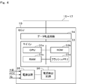
- FIG. 4 is a diagram showing an electrical configuration of the ECU.
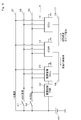
- FIG. 5 is a diagram showing a connection mode of the power supply line.
- FIG. 6 is a diagram showing an aspect of packaging the reprog data and the distribution specification data.
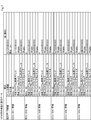
- FIG. 7 is a diagram showing rewriting specification data for DCM.
- FIG. 8 is a diagram showing rewriting specification data for CGW.
- FIG. 9 is a diagram showing distribution specification data.
- FIG. 1 is a diagram showing an overall configuration of one embodiment.
- FIG. 2 is a diagram showing the electrical configuration of the CGW.
- FIG. 3 is a diagram showing the electrical configuration of the DCM.
- FIG. 4 is a diagram showing an electrical configuration of the ECU.
- FIG. 5 is a diagram showing a connection mode of the power supply
- FIG. 10 is a diagram showing an aspect of unpackaging the distribution package.
- FIG. 11 is a diagram showing a mode during normal operation in an embedded single-sided single-sided memory.
- FIG. 12 is a diagram showing an aspect of the rewriting operation in the embedded single-sided single memory.
- FIG. 13 is a diagram showing a mode during normal operation in a download-type single-sided single-sided memory.
- FIG. 14 is a diagram showing a mode at the time of rewriting operation in the download type single-sided single memory.
- FIG. 15 is a diagram showing an aspect of a built-in one-sided suspend memory during normal operation.
- FIG. 16 is a diagram showing an aspect of a rewriting operation in the embedded one-sided suspend memory.
- FIG. 11 is a diagram showing a mode during normal operation in an embedded single-sided single-sided memory.
- FIG. 12 is a diagram showing an aspect of the rewriting operation in the embedded single-sided single memory.
- FIG. 13 is a diagram showing a
- FIG. 17 is a diagram showing a mode of normal operation in the download type one-sided suspend memory.
- FIG. 18 is a diagram showing a mode during the rewriting operation in the download type one-sided suspend memory.
- FIG. 19 is a diagram showing a mode during normal operation in the embedded two-sided memory.
- FIG. 20 is a diagram showing an aspect of the rewriting operation in the embedded two-sided memory.
- FIG. 21 is a diagram showing a mode of normal operation in the download type two-sided memory.
- FIG. 22 is a diagram showing a mode during the rewriting operation in the download type two-sided memory.
- FIG. 23 is a diagram showing a mode in which the application program is rewritten.
- FIG. 24 is a diagram showing a mode in which the application program is rewritten.
- FIG. 25 is a diagram showing a mode in which the application program is rewritten.
- FIG. 26 is a timing chart showing a mode in which the application program is rewritten by power control.
- FIG. 27 is a timing chart showing a mode in which the application program is rewritten by power control.
- FIG. 28 is a timing chart showing a mode in which the application program is rewritten by self-holding the power supply.
- FIG. 29 is a timing chart showing a mode in which the application program is rewritten by self-holding the power supply.
- FIG. 30 is a diagram showing phases.
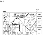
- FIG. 31 is a diagram showing a screen in a normal state.
- FIG. 32 is a diagram showing a screen when a campaign notification is generated.
- FIG. 33 is a diagram showing a screen at the time of campaign notification.
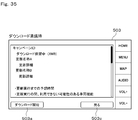
- FIG. 34 is a diagram showing a screen at the time of download acceptance.
- FIG. 35 is a diagram showing a screen at the time of download acceptance.
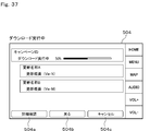
- FIG. 36 is a diagram showing a screen during download execution.
- FIG. 37 is a diagram showing a screen during download execution.
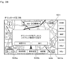
- FIG. 38 is a diagram showing a screen when the download is completed.
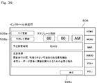
- FIG. 39 is a diagram showing a screen when the installation is approved.
- FIG. 40 is a diagram showing a screen when the installation is approved.
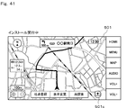
- FIG. 41 is a diagram showing a screen during installation.
- FIG. 42 is a diagram showing a screen during installation.
- FIG. 43 is a diagram showing a screen at the time of acceptance of activation.
- FIG. 44 is a diagram showing a screen when the IG is on.
- FIG. 45 is a diagram showing a screen at the time of the confirmation operation.
- FIG. 46 is a diagram showing a screen at the time of the confirmation operation.
- FIG. 47 is a functional block diagram of the center device.
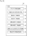
- FIG. 48 is a functional block diagram of the DCM.
- FIG. 49 is a functional block diagram of the CGW.
- FIG. 50 is a functional block diagram of the CGW.
- FIG. 51 is a functional block diagram of the ECU.
- FIG. 52 is a functional block diagram of the vehicle-mounted display.
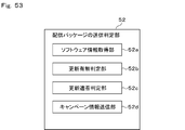
- FIG. 53 is a functional block diagram of the transmission determination unit of the distribution package.
- FIG. 54 is a flowchart showing a transmission determination process of the distribution package.
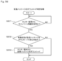
- FIG. 55 is a functional block diagram of the download determination unit of the distribution package.
- FIG. 56 is a flowchart showing the download determination process of the distribution package.
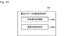
- FIG. 57 is a functional block diagram of the write data transfer determination unit.
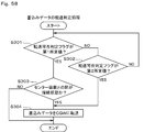
- FIG. 58 is a flowchart showing the transfer determination process of the write data.
- FIG. 59 is a functional block diagram of the write data acquisition determination unit.
- FIG. 60 is a flowchart showing the acquisition determination process of the write data.
- FIG. 61 is a functional block diagram of the installation instruction determination unit.
- FIG. 62 is a flowchart showing an installation instruction determination process.
- FIG. 63 is a diagram showing a mode for instructing installation.
- FIG. 64 is a diagram showing a mode for instructing installation.
- FIG. 65 is a diagram showing an aspect of generating a random number value.
- FIG. 66 is a functional block diagram of the security access key management unit.
- FIG. 67 is a flowchart showing a security access key generation process.
- FIG. 68 is a diagram showing an aspect of generating a security access key.
- FIG. 69 is a flowchart showing the security access key erasing process.
- FIG. 70 is a diagram showing a flow of processing involved in verification of written data.
- FIG. 71 is a functional block diagram of the write data verification unit.
- FIG. 72 is a flowchart showing the verification process of the write data.
- FIG. 73 is a diagram showing a mode in which the processes involved in the verification of the written data are distributed.
- FIG. 74 is a diagram showing a mode in which the processes involved in the verification of the written data are distributed.
- FIG. 75 is a diagram showing a mode in which the processes involved in the verification of the written data are distributed.
- FIG. 76 is a diagram showing a mode in which the processes involved in the verification of the written data are distributed.
- FIG. 77 is a diagram showing a flow of verification of written data and rewriting of an application program.
- FIG. 78 is a diagram showing a flow of verification of written data and rewriting of an application program.
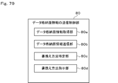
- FIG. 79 is a functional block diagram of the data storage surface information transmission control unit.
- FIG. 80 is a flowchart showing a transmission control process of data storage surface information.
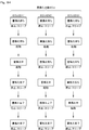
- FIG. 81 is a sequence diagram showing a mode of notifying the two-sided rewriting information.
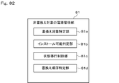
- FIG. 82 is a functional block diagram of the power management unit to be non-rewritten.
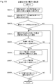
- FIG. 83 is a flowchart showing the power management process to be non-rewritten.
- FIG. 84 is a diagram showing transitions between a start state, a stop state, and a sleep state.
- FIG. 85 is a diagram showing transitions between a start state, a stop state, and a sleep state.
- FIG. 86 is a diagram showing a connection mode of the power supply line.
- FIG. 87 is a flowchart showing the monitoring process of the remaining battery level.
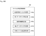
- FIG. 88 is a functional block diagram of the file transfer control unit.
- FIG. 89 is a flowchart showing a file transfer control process.
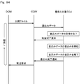
- FIG. 90 is a diagram showing a mode in which files are exchanged.
- FIG. 91 is a diagram showing a mode in which files are exchanged.
- FIG. 90 is a diagram showing a mode in which files are exchanged.
- FIG. 92 is a diagram showing a split file and a write file.
- FIG. 93 is a diagram showing a mode in which the CGW transmits a transfer request to the DCM.
- FIG. 94 is a diagram showing a mode in which the CGW transmits a transfer request to the DCM.
- FIG. 95 is a diagram showing a mode in which the CGW distributes the write data to the rewrite target ECU.
- FIG. 96 is a diagram showing a mode in which the CGW distributes the write data to the rewrite target ECU.
- FIG. 97 is a diagram showing a mode in which the CGW distributes the write data to the rewrite target ECU.
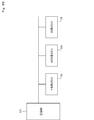
- FIG. 98 is a diagram showing an ECU connection mode.
- FIG. 99 is a functional block diagram of the write data distribution control unit.
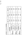
- FIG. 100 is a diagram showing a bus load table.
- FIG. 101 is a diagram showing a table belonging to the ECU to be rewritten.
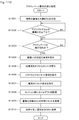
- FIG. 102 is a flowchart showing the distribution control process of the write data.
- FIG. 103 is a diagram showing a mode in which write data is distributed.
- FIG. 104 is a diagram showing a mode in which write data is distributed.
- FIG. 105 is a diagram showing a mode in which the written data while the vehicle is traveling is distributed.
- FIG. 106 is a diagram showing a mode in which write data during parking is distributed.
- FIG. 107 is a diagram showing a distribution amount of write data.
- FIG. 108 is a diagram showing a distribution amount of write data.
- FIG. 100 is a diagram showing a bus load table.
- FIG. 101 is a diagram showing a table belonging to the ECU to be rewritten.
- FIG. 109 is a functional block diagram of the activation request indicator.
- FIG. 110 is a flowchart showing the instruction processing of the activation request.
- FIG. 111 is a diagram showing an aspect of instructing an activation request.
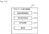
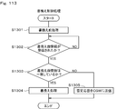
- FIG. 112 is a functional block diagram of the activation execution control unit.
- FIG. 113 is a flowchart showing the rewriting process.
- FIG. 114 is a flowchart showing the execution control process of activation.
- FIG. 115 is a functional block diagram of the grouping unit to be rewritten.
- FIG. 116 is a flowchart showing a group management process to be rewritten.
- FIG. 117 is a flowchart showing a group management process to be rewritten.
- FIG. 118 is a diagram showing an aspect of grouping rewrite targets.
- FIG. 119 is a functional block diagram of the rollback execution control unit.
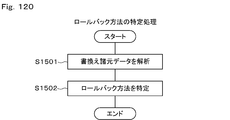
- FIG. 120 is a flowchart showing a specific process of the rollback method.
- FIG. 121 is a flowchart showing a cancellation request determination process.
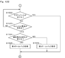
- FIG. 122 is a flowchart showing a cancellation request determination process.
- FIG. 123 is a flowchart showing a cancellation request determination process.
- FIG. 124 is a flowchart showing a cancellation request determination process.
- FIG. 125 is a flowchart showing a cancellation request determination process.
- FIG. 126 is a diagram showing a mode in which rollback is performed.
- FIG. 127 is a diagram showing a mode in which rollback is performed.
- FIG. 128 is a diagram showing a mode in which rollback is performed.
- FIG. 126 is a diagram showing a mode in which rollback is performed.
- FIG. 127 is a diagram showing a mode in which rollback is performed.
- FIG. 128 is a
- FIG. 129 is a diagram showing a mode in which rollback is executed.
- FIG. 130 is a diagram showing a mode in which rollback is performed.
- FIG. 131 is a functional block diagram of the display control unit of the rewriting progress status.
- FIG. 132 is a flowchart showing a display control process of the rewriting progress status.
- FIG. 133 is a flowchart showing the display control process of the rewriting progress status.
- FIG. 134 is a diagram showing a screen of the rewriting progress status.
- FIG. 135 is a diagram showing a screen of the rewriting progress status.
- FIG. 136 is a diagram showing a screen of the rewriting progress status.
- FIG. 137 is a diagram showing a screen of the rewriting progress status.
- FIG. 129 is a diagram showing a mode in which rollback is executed.
- FIG. 130 is a diagram showing a mode in which rollback is performed.
- FIG. 131 is a functional
- FIG. 138 is a diagram showing a screen of the rewriting progress status.
- FIG. 139 is a diagram showing a transition of the progress graph display.
- FIG. 140 is a diagram showing a transition of the progress graph display.
- FIG. 141 is a diagram showing a transition of the progress graph display.
- FIG. 142 is a diagram showing a transition of the progress graph display.
- FIG. 143 is a diagram showing a screen of the rewriting progress status.
- FIG. 144 is a functional block diagram of the consistency determination unit for the difference data.
- FIG. 145 is a flowchart showing the consistency determination process of the difference data.
- FIG. 146 is a diagram showing a mode for determining the consistency of the difference data.
- FIG. 139 is a diagram showing a transition of the progress graph display.
- FIG. 140 is a diagram showing a transition of the progress graph display.
- FIG. 141 is a diagram showing a transition of the progress graph display.
- FIG. 142
- FIG. 147 is a diagram showing a mode for determining the consistency of the difference data.
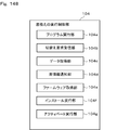
- FIG. 148 is a functional block diagram of the rewriting execution control unit.
- FIG. 149 is a flowchart showing a normal operation process.
- FIG. 150 is a flowchart showing the rewriting operation process.
- FIG. 151 is a flowchart showing the information notification process.
- FIG. 152 is a flowchart showing the verification process of the rewriting program.
- FIG. 153 is a diagram showing a mode in which identification information and write data are transmitted.
- FIG. 154 is a diagram showing a mode in which identification information and write data are transmitted.
- FIG. 155 is a flowchart showing an installation instruction process.
- FIG. 156 is a functional block diagram of the session establishment unit.
- FIG. 156 is a functional block diagram of the session establishment unit.
- FIG. 157 is a diagram showing the structure of the program.
- FIG. 158 is a diagram showing a state transition.
- FIG. 159 is a diagram showing a state transition.
- FIG. 160 is a diagram showing a state transition.
- FIG. 161 is a diagram showing session arbitration.
- FIG. 162 is a diagram showing session arbitration.
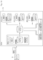
- FIG. 163 is a flowchart showing the state transition management process of the first state.
- FIG. 164 is a flowchart showing the state transition management process of the first state.
- FIG. 165 is a flowchart showing the state transition management process of the first state.
- FIG. 166 is a flowchart showing the state transition management process of the second state.
- FIG. 167 is a flowchart showing the state transition management process of the second state.
- FIG. 168 is a diagram showing the structure of the program.
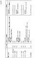
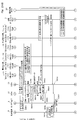
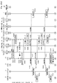
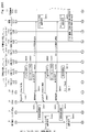
- FIG. 169 is a diagram showing a state transition.
- FIG. 170 is a functional block diagram of a specific part of the retry point.
- FIG. 171 is a diagram showing a configuration of a flash memory.
- FIG. 172 is a flowchart showing a processing flag setting process.
- FIG. 173 is a flowchart showing a processing flag determination process.
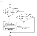
- FIG. 174 is a flowchart showing the process flag determination process.
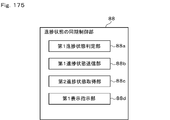
- FIG. 175 is a functional block diagram of the synchronization control unit in the progress state.
- FIG. 176 is a functional block diagram of the synchronization control unit in the progress state.
- FIG. 177 is a diagram showing a mode in which a progress status signal is transmitted / received.
- FIG. 178 is a flowchart showing the synchronization control process of the progress state.
- FIG. 179 is a flowchart showing the synchronization control process of the progress state.
- FIG. 180 is a flowchart showing a progress status display process.
- FIG. 181 is a functional block diagram of the display control information transmission control unit.
- FIG. 182 is a flowchart showing a transmission control process of display control information.
- FIG. 183 is a functional block diagram of the display control information reception control unit.
- FIG. 184 is a flowchart showing a reception control process of display control information.
- FIG. 185 is a diagram showing information included in the distribution specification data.
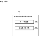
- FIG. 186 is a functional block diagram of the screen display control unit for progress display.
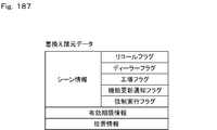
- FIG. 187 is a diagram showing rewriting specification data.
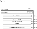
- FIG. 188 is a diagram showing a screen when a menu is selected.
- FIG. 189 is a diagram showing a screen at the time of user selection.
- FIG. 190 is a diagram showing a screen at the time of user registration.
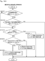
- FIG. 191 is a flowchart showing the screen display control process of the progress display.
- FIG. 192 is a flowchart showing the screen display control process of the progress display.
- FIG. 193 is a diagram showing a message frame.
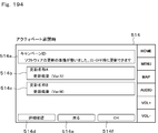
- FIG. 194 is a diagram showing a screen at the time of acceptance of activation.
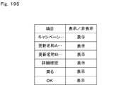
- FIG. 195 is a diagram showing the setting of whether or not to display the item.
- FIG. 196 is a diagram showing the setting of whether or not to display the item.
- FIG. 196 is a diagram showing the setting of whether or not to display the item.
- FIG. 197 is a diagram showing a screen at the time of acceptance of activation.
- FIG. 198 is a diagram showing a mode of data communication.
- FIG. 199 is a diagram showing a message frame at the time of campaign notification.
- FIG. 200 is a diagram showing a message frame at the time of download acceptance.
- FIG. 201 is a diagram showing a message frame when the installation is accepted.
- FIG. 202 is a diagram showing a message frame at the time of acceptance of activation.
- FIG. 203 is a diagram showing screen transitions.
- FIG. 204 is a diagram showing a screen when a campaign notification is generated.
- FIG. 205 is a diagram showing a screen at the time of download acceptance.
- FIG. 206 is a diagram showing a screen at the time of download acceptance.
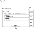
- FIG. 207 is a diagram showing a screen during download execution.
- FIG. 208 is a diagram showing a screen when the download is completed.
- FIG. 209 is a diagram showing a screen when the installation is approved.
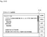
- FIG. 210 is a diagram showing a screen at the time of acceptance of activation.
- FIG. 211 is a functional block diagram of the program update notification control unit.
- FIG. 212 is a flowchart showing a program update notification control process.
- FIG. 213 is a diagram showing a notification mode of the indicator.
- FIG. 214 is a diagram showing a transition of the notification mode when the rewriting target is a two-sided memory.
- FIG. 215 is a diagram showing a transition of the notification mode when the rewriting target is the one-sided suspend memory.
- FIG. 216 is a diagram showing a transition of the notification mode when the rewriting target is a single-sided single memory.
- FIG. 217 is a diagram showing a connection mode.
- FIG. 218 is a functional block of the execution control unit for self-holding the power supply in the CGW.
- FIG. 219 is a functional block of the execution control unit for self-holding the power supply in the ECU.
- FIG. 220 is a flowchart showing the execution control process of power supply self-holding in CGW.
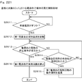
- FIG. 221 is a flowchart showing the execution control process of power supply self-holding in the ECU.
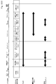
- FIG. 222 is a diagram showing a period in which power supply self-holding is required.
- FIG. 223 is a functional block diagram of the rewrite instruction unit by overwriting the config information.
- FIG. 224 is a flowchart showing a rewrite instruction process by overwriting the config information.
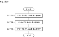
- FIG. 225 is a diagram showing a mode in which rewriting of the application program and overwriting of config information are mixed.
- FIG. 226 is a diagram showing a mode in which rewriting of the application program and overwriting of config information are mixed.
- FIG. 227 is a diagram showing a mode for transmitting and receiving config information.
- FIG. 228 is a functional block of the rewriting instruction unit by writing back the config information.
- FIG. 229 is a flowchart showing a rewrite instruction process by rewriting the config information.
- FIG. 230 is a flowchart showing a rewrite instruction process by rewriting the config information.
- FIG. 231 is a flowchart showing a rewrite instruction process by rewriting the config information.
- FIG. 232 is a diagram showing a mode in which rewriting of the application program and rewriting of the config information are mixed.
- FIG. 233 is a diagram showing a mode in which rewriting of the application program and rewriting of the config information are mixed.
- FIG. 234 is a diagram showing a mode in which rewriting of the application program and rewriting of the config information are mixed.
- FIG. 235 is a diagram showing a mode in which rewriting of the application program and rewriting of the config information are mixed.
- FIG. 236 is a diagram showing a mode in which rewriting of the application program and rewriting of the config information are mixed.
- FIG. 237 is a diagram showing a mode in which rewriting of the application program and rewriting of the config information are mixed.
- FIG. 238 is a diagram showing a mode for transmitting and receiving config information.
- FIG. 239 is a diagram showing a mode for transmitting and receiving config information.
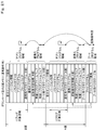
- FIG. 240 is a diagram showing a configuration of a flash memory.
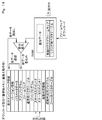
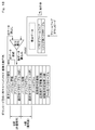
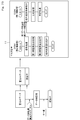
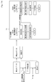
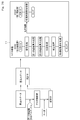
- FIG. 241 is a functional block diagram of the rewrite instruction unit in the specific mode.
- FIG. 242 is a diagram showing a mode of connecting to factory equipment.
- FIG. 243 is a diagram showing a mode of connecting to the dealer equipment.
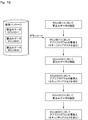
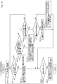
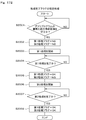
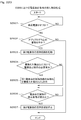
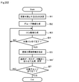
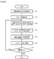
- FIG. 244 is a flowchart showing the rewriting instruction processing in the specific mode.
- FIG. 245 is a flowchart showing the rewriting process in the specific mode.
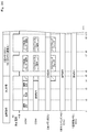
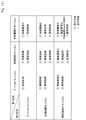
- FIG. 246 is a diagram showing the contents of rewriting in the factory mode and rewriting in the dealer mode.
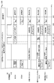
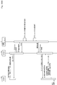
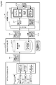
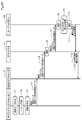
- FIG. 247 is an overall sequence diagram showing a mode in which the application program is rewritten.
- FIG. 248 is an overall sequence diagram showing a mode in which the application program is rewritten.
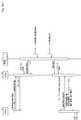
- FIG. 249 is an overall sequence diagram showing a mode in which the application program is rewritten.
- FIG. 250 is an overall sequence diagram showing a mode in which the application program is rewritten.
- FIG. 251 is an overall sequence diagram showing a mode in which the application program is rewritten.
- FIG. 252 is an overall sequence diagram showing a mode in which the application program is rewritten.
- FIG. 253 is an overall sequence diagram showing a mode in which the application program is rewritten.
- FIG. 254 is an overall sequence diagram showing a mode in which the application program is rewritten.
- FIG. 255 is an overall sequence diagram showing a mode in which the application program is rewritten.
- FIG. 256 is an overall sequence diagram showing a mode in which the application program is rewritten.
- FIG. 257 is an overall sequence diagram showing a mode in which the application program is rewritten.
- FIG. 258 is a diagram showing the overall configuration of the vehicle information communication system in the first embodiment.
- FIG. 259 is a diagram showing the electrical configuration of the CGW.
- FIG. 260 is a diagram showing an electrical configuration of the ECU.
- FIG. 261 is a diagram showing a connection mode of the power supply line.
- FIG. 262 is a diagram showing an aspect of packaging the reprolog data and the distribution specification data.
- FIG. 263 is a diagram showing a mode of unpackaging the distribution package.
- FIG. 264 is a block diagram showing a portion of the center device mainly related to each function of the server.
- FIG. 265 is an image diagram showing a processing flow in the center device.
- FIG. 266 is a diagram showing an example of vehicle configuration information registered in the configuration information DB.
- FIG. 267 is a diagram showing an example of programs and data registered in the ECU repro data DB.
- FIG. 268 is a diagram showing an example of specification data registered in the ECU metadata DB.
- FIG. 269 is a diagram showing an example of vehicle configuration information registered in the individual vehicle information DB.
- FIG. 270 is a diagram showing an example of distribution package data registered in the package DB.
- FIG. 271 is a diagram showing an example of campaign data registered in the campaign DB.
- FIG. 272 is a flowchart showing a process of generating a program and data registered in the ECU repro data DB.
- FIG. 273 is a flowchart showing a process of generating an example of specification data registered in the ECU metadata DB.
- FIG. 274 is a diagram showing an example of specification data.
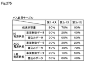
- FIG. 275 is a diagram showing an example of a bus load table.
- FIG. 276 is a flowchart showing a process of generating a distribution package registered in the package DB.
- FIG. 277 is a diagram showing the contents of the package file as an image.
- FIG. 278 is a sequence diagram showing a processing procedure executed between the center device and the vehicle side system in the second embodiment.
- FIG. 279 is a flowchart showing the processing performed by the center device.
- FIG. 280 is a diagram imaginatively showing the processing contents performed in steps D6 and D7 of the flowchart shown in FIG. 279.
- FIG. 281 is a flowchart showing a process when a hash value is transmitted from the vehicle side system to the center device.
- FIG. 282 is a sequence diagram showing a processing procedure executed between the center device and the vehicle side system in the third embodiment.
- FIG. 283 is a flowchart showing the processing performed by the center device.
- FIG. 284 is a sequence diagram showing a state in which the center device notifies each of the EV vehicle and the combe vehicle by SMS.
- FIG. 285 is a sequence diagram showing a processing procedure executed between the center device and the vehicle side system in the fourth embodiment.
- FIG. 286 is a diagram imaginatively showing the processing performed between the supplier, the center device, and the vehicle side system in the fifth embodiment.
- FIG. 287 is a sequence diagram (No. 1) showing a processing procedure performed between the supplier, the center device, and the vehicle-side system.
- FIG. 288 is a sequence diagram (No. 2) showing a processing procedure performed between the supplier, the center device, and the vehicle-side system.
- FIG. 1 shows a processing procedure performed between the supplier, the center device, and the vehicle-side system.
- FIG. 289 is a sequence diagram (No. 3) showing a processing procedure performed between the supplier, the center device, and the vehicle-side system.
- FIG. 290 is a modification of the first embodiment (No. 1), and is a diagram showing a data format of a package DB when a plurality of packages are associated with one campaign.
- FIG. 291 is a diagram showing a data format of a campaign DB when a plurality of packages are associated with one campaign.
- FIG. 292 is a diagram corresponding to FIG. 273 when specification data is generated for each group.
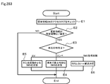
- FIG. 293 is a diagram corresponding to FIG. 276 in the case where the distribution package is generated for each group.
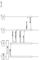
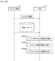
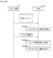
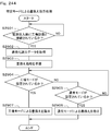
- FIG. 294 is a modification (No. 2) of the first embodiment, and is a diagram showing the processing contents of the package generation tool.
- the vehicle program rewriting system (corresponding to the vehicle electronic control system) is an OTA (OverThe) application program for vehicle control and diagnosis installed in an electronic control device (hereinafter referred to as an ECU (Electronic Control Unit)). It is a system that can be rewritten by Air).
- ECU Electronic Control Unit
- Air an electronic control device
- a case where the application program is rewritten by wire or wirelessly will be described.
- data used by various applications such as map data used by a map application and control parameters used by an ECU will be transmitted by wire or wirelessly. It can also be applied when rewriting with.
- Wired app program rewriting involves acquiring and rewriting the app program from outside the vehicle via wire, and also acquiring various data used when the app program is executed from outside the vehicle via wire. Including rewriting.
- To rewrite the app program wirelessly in addition to acquiring and rewriting the app program wirelessly from outside the vehicle, various data used when the app program is executed are acquired wirelessly from outside the vehicle. Including rewriting.
- the vehicle program rewriting system 1 has a center device 3 on the communication network 2 side, a vehicle side system 4 on the vehicle side, and a display terminal 5.
- the communication network 2 includes, for example, a mobile communication network using a 4G line or the like, the Internet, WiFi (Wireless Fidelity) (registered trademark), and the like.
- WiFi Wireless Fidelity
- the configuration on the vehicle side will be mainly described, and the configuration of the center device 3 will be described in detail in FIGS. 234 to 270.
- the display terminal 5 is a terminal having a function of receiving operation input from a user and a function of displaying various screens.
- a mobile terminal 6 such as a smartphone or tablet that the user can carry, or an in-vehicle display arranged in a vehicle interior. It is 7.
- the mobile terminal 6 can perform data communication with the center device 3 via the communication network 2 as long as it is within the communication range of the mobile communication network.
- the in-vehicle display 7 may be connected to the vehicle-side system 4 and may also have a navigation function. Further, the in-vehicle display 7 may be an in-vehicle display ECU having an ECU function, or may have a function of controlling display on a center display, a meter display, or the like.
- the user inputs an operation while checking various screens involved in the rewriting of the application program on the mobile terminal 6, and performs a procedure related to the rewriting of the application program. It is possible. In the vehicle interior, the user can perform an operation input while checking various screens involved in the rewriting of the application program on the in-vehicle display 7, and perform a procedure related to the rewriting of the application program. That is, the user can properly use the mobile terminal 6 and the in-vehicle display 7 outside and inside the vehicle, and can perform procedures involved in rewriting the application program.
- the center device 3 controls the program update function on the communication network 2 side in the vehicle program rewriting system 1 and functions as an OTA center.
- the center device 3 has a file server 8, a web server 9, and a management server 10, and the servers 8 to 10 are configured to enable data communication with each other. That is, the center device 3 is configured to include a plurality of servers that are different for each function.
- the file server 8 is a server that manages the files of the application program distributed from the center device 3 to the vehicle side system 4.
- the file server 8 is an update data (hereinafter, also referred to as replog data or write data) provided by a supplier or the like that is a provider of an application program distributed from the center device 3 to the vehicle side system 4, and an OEM (Original Equipment Manufacturer). ),
- the distribution specification data, the vehicle state acquired from the vehicle side system 4, and the like are managed.
- the file server 8 is capable of data communication with the vehicle-side system 4 via the communication network 2, and when a download request for the distribution package is generated, the reprog data and the distribution specification data are packaged into one file.
- the delivery package is transmitted to the vehicle side system 4.
- the web server 9 is a server that manages web information.
- the web server 9 transmits web data managed by itself in response to a request from a web browser possessed by the mobile terminal 6 or the like.
- the management server 10 is a server that manages personal information of users registered in the application program rewriting service, application program rewriting history for each vehicle, and the like.
- the vehicle side system 4 has a master device 11 (corresponding to a vehicle master device).
- the master device 11 has a DCM (Data Communication Module) 12 (corresponding to an in-vehicle communication device) and a CGW (CentralGate Way) 13 (corresponding to a vehicle gateway device).
- the DCM12 and the CGW 13 are connected so as to be capable of data communication via the first bus 14.
- the DCM 12 performs data communication with the center device 3 via the communication network 2.
- the DCM12 downloads the distribution package from the file server 8, it extracts the write data from the downloaded distribution package and transfers the extracted write data to the CGW 13.
- the CGW 13 has a data relay function, and when it acquires write data from the DCM12, it instructs the rewrite target ECU, which is the rewrite target of the application program, to write the acquired write data, and distributes the write data to the rewrite target ECU. Further, when the writing of the writing data is completed in the rewriting target ECU and the rewriting of the application program is completed, the CGW 13 instructs the rewriting target ECU to activate the application program after the rewriting is completed.
- the master device 11 controls the program update function on the vehicle side in the vehicle program rewriting system 1 and functions as an OTA master.
- FIG. 1 illustrates a configuration in which the DCM 12 and the vehicle-mounted display 7 are connected to the same first bus 14, the DCM 12 and the vehicle-mounted display 7 may be connected to different buses.
- the CGW 13 may have a part or the whole of the functions of the DCM12, or the DCM12 may have a part or the whole of the functions of the CGW 13. That is, in the master device 11, the division of functions between the DCM 12 and the CGW 13 may be configured in any way.
- the master device 11 may be composed of two ECUs of DCM12 and CGW13, or may be composed of one integrated ECU having a function of DCM12 and a function of CGW13.
- the second bus 15, the third bus 16, the fourth bus 17, and the fifth bus 18 are connected to the CGW 13 as buses inside the vehicle, and the buses 15 to 17 are connected to the CGW 13.
- Various ECUs 19 are connected via the bus 18, and the power management ECU 20 is connected via the bus 18.
- the second bus 15 is, for example, a body network bus.
- the ECU 19 connected to the second bus 15 is an ECU that controls the body system.
- the ECU that controls the body system is, for example, a door ECU that controls the lock / unlock of the door, a meter ECU that controls the display on the meter display, an air conditioner ECU that controls the drive of the air conditioner, and a window ECU that controls the opening and closing of the window.
- a security ECU that is driven to prevent theft of the vehicle.
- the third bus 16 is, for example, a bus of a traveling network.
- the ECU 19 connected to the third bus 16 is an ECU that controls the traveling system.
- the ECU that controls the traveling system is, for example, an engine ECU that controls engine drive, a brake ECU that controls brake drive, an ECT (Electronic Controlled Transmission) ECU that controls automatic transmission drive, and power steering drive control. Power steering ECU and the like.
- the fourth bus 17 is, for example, a multimedia network bus.
- the ECU 19 connected to the fourth bus 17 is an ECU that controls the multimedia system.
- the ECU that controls the multimedia system is, for example, a navigation ECU for controlling a navigation system, an ETC ECU for controlling an electronic toll collection system (ETC (Electronic Toll Collection System, registered trademark)), and the like.
- the buses 15 to 17 may be buses of a system other than the body network bus, the traveling network bus, and the multimedia network bus. Further, the number of buses and the number of ECUs 19 are not limited to the illustrated configuration.
- the power management ECU 20 is an ECU that manages power supplied to the DCM12, CGW13, various ECUs 19, and the like.
- the sixth bus 21 is connected to the CGW 13 as a bus outside the vehicle.
- a DLC (Data Link Coupler) connector 22 to which a tool 23 (corresponding to a service tool) is detachably connected is connected to the sixth bus 21.
- Buses 14 to 18 on the inside of the vehicle and buses 21 on the outside of the vehicle are composed of, for example, CAN (Controller Area Network, registered trademark) buses, and CGW 13 is a CAN data communication standard and a diagnostic communication standard (UDS (Unified Diagnosis Services). ): Data communication is performed between the DCM12, various ECUs 19, and the tool 23 according to ISO14229).
- the DCM12 and the CGW 13 may be connected by an Ethernet, or the DLC connector 22 and the CGW 13 may be connected by an Ethernet.
- the rewrite target ECU 19 When the rewrite target ECU 19 receives the write data from the CGW 13, it writes the received write data to the flash memory (corresponding to the non-volatile memory) and rewrites the application program.
- the CGW 13 when the CGW 13 receives the write data acquisition request from the rewrite target ECU 19, the CGW 13 functions as a reprolog master that distributes the write data to the rewrite target ECU 19.
- the rewrite target ECU 19 functions as a reprolog slave that writes the received write data to the flash memory and rewrites the application program.
- the mode of rewriting the application program by wire is a mode of rewriting the rewriting target ECU 19 by using the application program acquired from the outside of the vehicle via wire.
- the CGW 13 functions as a gateway, transmits a wired rewrite request to the rewrite target ECU 19, instructs the rewrite target ECU 19 to write (install) the write data, and distributes the write data transferred from the tool 23 to the rewrite target ECU 19. Distributing the write data to the rewrite target ECU 19 is to relay the write data.
- the mode of wirelessly rewriting the application program is a mode of rewriting the rewriting target ECU 19 using the application program acquired wirelessly from the outside of the vehicle.
- the DCM12 downloads the distribution package from the file server 8, it extracts the write data from the downloaded distribution package and transfers the write data to the CGW 13.
- the CGW 13 functions as a rewrite tool, instructs the rewrite target ECU 19 to write (install) the write data, and distributes the write data transferred from the DCM 12 to the rewrite target ECU 19.
- the mode of diagnosing by wire is a mode of diagnosing the ECU 19 from outside the vehicle via wire.
- the CGW 13 functions as a gateway, transmits a diagnosis request to the diagnosis target ECU 19, and delivers the diagnosis command transferred from the tool 23 to the diagnosis target ECU 19.
- the diagnosis target ECU 19 performs diagnostic processing according to the diagnostic command received from the CGW 13.
- the wireless diagnosis mode is a mode in which the ECU 19 is diagnosed wirelessly from the outside of the vehicle. Specifically, when a diagnostic command is transmitted from the center device 3 to the DCM 12 as a diagnostic request, the DCM 12 transfers the diagnostic command to the CGW 13.
- the CGW 13 functions as a gateway and delivers a diagnostic command to the diagnostic target ECU 19 as a diagnostic request.
- the diagnosis target ECU performs diagnostic processing according to the diagnostic command received from the CGW 13.
- the CGW 13 has a microcomputer (hereinafter referred to as a microcomputer) 24, a data transfer circuit 25, a power supply circuit 26, and a power supply detection circuit 27 as electrical functional blocks.
- the microcomputer 24 has a CPU (Central Processing Unit) 24a, a ROM (Read Only Memory) 24b, a RAM (Random Access Memory) 24c, and a flash memory 24d.
- the flash memory 24d includes a secure area in which information cannot be read from the outside of the CGW 13.
- the microcomputer 24 executes various control programs stored in the non-transitional substantive storage medium to perform various processes, and controls the operation of the CGW 13.
- the data transfer circuit 25 controls data communication between buses 14 to 18 and 21 in accordance with CAN data communication standards and diagnostic communication standards.
- the power supply circuit 26 inputs a battery power supply (hereinafter referred to as + B power supply), an accessory power supply (hereinafter referred to as ACC power supply), and an ignition power supply (hereinafter referred to as IG power supply).
- the power supply detection circuit 27 detects the voltage value of the + B power supply, the voltage value of the ACC power supply, and the voltage value of the IG power supply input by the power supply circuit 26, compares these detected voltage values with a predetermined voltage threshold value, and compares them. The result is output to the microcomputer 24.
- the microcomputer 24 determines whether the + B power supply, the ACC power supply, and the IG power supply supplied to the CGW 13 from the outside are normal or abnormal based on the comparison result input from the power supply detection circuit 27.
- the DCM 12 has a microcomputer 28, a wireless circuit 29, a data transfer circuit 30, a power supply circuit 31, and a power supply detection circuit 32 as electrical functional blocks.
- the microcomputer 28 has a CPU 28a, a ROM 28b, a RAM 28c, and a flash memory 28d.
- the flash memory 28d includes a secure area in which information cannot be read from the outside of the DCM12.
- the microcomputer 28 executes various control programs stored in the non-transitional substantive storage medium to perform various processes, and controls the operation of the DCM12.
- the flash memory for storing the data downloaded from the center device 3 may be arranged in the CGW 13.
- the wireless circuit 29 controls data communication with the center device 3 via the communication network 2.
- the data transfer circuit 30 controls data communication with the bus 14 in conformity with the CAN data communication standard.
- the power supply circuit 31 inputs + B power supply, ACC power supply, and IG power supply.
- the power supply detection circuit 32 detects the voltage value of the + B power supply input by the power supply circuit 31, the voltage value of the ACC power supply, and the voltage value of the IG power supply, compares these detected voltage values with a predetermined voltage threshold value, and compares them. The result is output to the microcomputer 28.
- the microcomputer 28 determines whether the + B power supply, the ACC power supply, and the IG power supply supplied to the DCM 12 from the outside are normal or abnormal based on the comparison result input from the power supply detection circuit 32.
- the DCM12 has a vehicle position detection function that detects the vehicle position by, for example, GPS (Global Positioning System).
- the flash memory 28d of the DCM12 has a sufficient memory capacity that can store the distribution package downloaded from the center device 3, and has a memory capacity larger than that of the flash memory 24d of the CGW 13. That is, since the flash memory 28d of the DCM12 has a sufficient memory capacity, even if the flash memory 24d of the CGW 13 does not have a sufficient memory capacity, the distribution package can be delivered from the center device 3 in the master device 11. It is possible to download and store the downloaded distribution package in DCM12.
- the ECU 19 has a microcomputer 33, a data transfer circuit 34, a power supply circuit 35, and a power supply detection circuit 36 as electrical functional blocks.
- the microcomputer 33 has a CPU 28a, a ROM 28b, a RAM 33c, and a flash memory 28d.
- the flash memory 28d includes a secure area in which information cannot be read from the outside of the ECU 19.
- the microcomputer 33 executes various control programs stored in the non-transitional substantive storage medium to perform various processes, and controls the operation of the ECU 19.
- the data transfer circuit 34 controls data communication between the buses 15 to 17 in accordance with the CAN data communication standard.
- the power supply circuit 35 inputs + B power supply, ACC power supply, and IG power supply.
- the power supply detection circuit 36 detects the voltage value of the + B power supply, the voltage value of the ACC power supply, and the voltage value of the IG power supply input by the power supply circuit 35, compares these detected voltage values with a predetermined voltage threshold value, and compares them. The result is output to the microcomputer 33.
- the microcomputer 33 determines whether the + B power supply, the ACC power supply, and the IG power supply supplied to the ECU 19 from the outside are normal or abnormal based on the comparison result input from the power supply detection circuit 27. It should be noted that the ECU 19 has basically the same configuration because the loads of the sensors and actuators to which it is connected are different.
- the in-vehicle display 7 has the same configuration as the ECU 19 shown in FIG.
- the power management ECU 20 has the same configuration as the ECU 19 shown in FIG.
- the power management ECU 20 is connected to the power control circuit 43, which will be described later, so that data communication is possible.
- the power management ECU 20, CGW 13, and ECU 19 are connected to the + B power supply line 37, the ACC power supply line 38, and the IG power supply line 39, which are power supply lines.
- the + B power supply line 37 is connected to the positive electrode of the vehicle battery 40.
- the ACC power supply line 38 is connected to the positive electrode of the vehicle battery 40 via the ACC switch 41. When the user performs the ACC operation, the ACC switch 41 is switched from off to on, and the output voltage of the vehicle battery 40 is applied to the ACC power supply line 38.
- the ACC operation is, for example, in the case of a vehicle in which the key is inserted into the insertion port, the key is inserted into the insertion port and the operation is rotated from the "OFF" position to the "ACC" position.
- the start button is pressed once.
- the IG power supply line 39 is connected to the positive electrode of the vehicle battery 40 via the IG switch 42.
- the IG switch 42 is switched from off to on, and the output voltage of the vehicle battery 40 is applied to the IG power supply line 39.
- the IG operation is an operation in which the key is inserted into the insertion port and rotated from the "OFF" position to the "ON" position, and the start button is pressed.
- the start button is pressed twice.
- the negative electrode of the vehicle battery 40 is grounded.
- both the ACC switch 41 and the IG switch 42 are off, only + B power is supplied to the vehicle side system 4.
- the state in which only the + B power supply is supplied to the vehicle side system 4 is referred to as the + B power supply state.
- the ACC switch 41 is on and the IG switch 42 is off, the ACC power supply and the + B power supply are supplied to the vehicle side system 4.
- the state in which the ACC power supply and the + B power supply are supplied to the vehicle side system 4 is referred to as an ACC power supply state.
- the + B power supply, the ACC power supply, and the IG power supply are supplied to the vehicle side system 4.
- the state in which the + B power supply, the ACC power supply, and the IG power supply are supplied to the vehicle side system 4 is referred to as an IG power supply state. Further, in addition to the above-mentioned power supply states, a power supply state that provides a power supply suitable for wireless program update can be considered.
- the start condition differs depending on the power supply state, and the ECU 19 is classified into a + B power supply system ECU that starts in the + B power supply state, an ACC system ECU that starts in the ACC power supply state, and an IG system ECU that starts in the IG power supply state.
- the ECU 19 that is driven for purposes such as vehicle theft is classified into a + B power supply system ECU.
- the ECU 19 driven for non-traveling applications such as audio is classified into an ACC system ECU.
- the ECU 19 that is driven for traveling system applications such as engine control is classified into an IG system ECU.
- the + B power supply system ECU is connected to the + B power supply line 37, the ACC power supply line 38, and the IG power supply line 39, and selects the + B power supply line 37 when the + B power supply state is selected, and selects the ACC power supply line 38 when the + B power supply state is used. It is configured to select the IG power supply line 39 in the IG power supply state.
- the ACC system ECU is connected to the ACC power supply line 38 and the IG power supply line 39, and is configured to select the ACC power supply line 38 in the ACC power supply state and select the IG power supply line 39 in the IG power supply state.
- the IG system ECU is connected to the IG power supply line 39.
- the CGW 13 By transmitting a start request to the ECU 19 in the sleep state, the CGW 13 shifts the ECU 19 to which the start request is sent from the sleep state to the start state. Further, the CGW 13 transmits a sleep request to the ECU 19 in the activated state to shift the ECU 19 to which the sleep request is transmitted from the activated state to the sleep state.
- the CGW 13 can shift the specific ECU 19 to the activated state or the sleep state by, for example, changing the waveform of the transmission signal transmitted to the buses 15 to 17.
- the activation request waveform and the sleep request waveform are predetermined for each ECU 19, and when the ECU 19 receives the activation request waveform that suits itself, it shifts from the sleep state to the activation state, and the CGW 13 shifts to the sleep request that suits itself. When the waveform is received, it shifts from the startup state to the sleep state.
- the CGW 13 shifts the ECU (ID1) from the activated state to the sleep state by transmitting the first waveform when the ECU (ID1) and the ECU (ID2) are in the activated state, and puts the ECU (ID2) in the activated state. Hold. Further, the CGW 13 keeps the ECU (ID1) in the activated state by transmitting the second waveform when the ECU (ID1) and the ECU (ID2) are in the activated state, and keeps the ECU (ID2) in the activated state to the sleep state. Migrate to.
- the power supply control circuit 43 is connected in parallel to the ACC switch 41 and the IG switch 42.
- the CGW 13 transmits a power control request to the power management ECU 20 and causes the power management ECU 20 to control the power control circuit 43. That is, the CGW 13 transmits a power supply start request as a power supply control request to the power supply management ECU 20, thereby connecting the ACC power supply line 38 or the IG power supply line 39 and the positive electrode of the vehicle battery 40 inside the power supply control circuit 43. In this state, the ACC power supply and the IG power supply are supplied to the vehicle side system 4 even when the ACC switch 41 and the IG switch 42 are off.
- the CGW 13 transmits a power supply stop request as a power supply control request to the power management ECU 20, thereby interrupting the ACC power supply line 38, the IG power supply line 39, and the positive electrode of the vehicle battery 40 inside the power supply control circuit 43.
- the DCM12, CGW 13, ECU 19, and power management ECU 20 each have a power supply self-holding circuit, and have a power supply self-holding function for holding the power supply from the vehicle battery 40. That is, in the DCM12, CGW 13, and ECU 19, when the power management ECU 20 is in the activated state and the vehicle power supply is switched from the ACC power supply or the IG power supply to the + B power supply, the power management ECU 20 is in the stopped state or the sleep state immediately after the switching. Instead of shifting to, the start-up state is continuously maintained for a predetermined time (for example, several minutes) by supplying power from the vehicle battery 40, and the drive power supply is self-held.
- a predetermined time for example, several minutes
- the DCM12, CGW 13, ECU 19, and power management ECU 20 shift from the start state to the stop state or the sleep state after a predetermined time has elapsed immediately after the vehicle power supply is switched from the ACC power supply or the IG power supply to the + B power supply.
- various data related to engine control acquired while the vehicle is running is used as a log by operating the power supply self-holding function after the vehicle power supply is switched from the ACC power supply or the IG power supply to the + B power supply.
- the distribution package delivered from the center device 3 to the master device 11 will be described.
- the writing data provided by the supplier who is the provider of the application program and the rewriting specification data provided by the OEM (corresponding to the specification data).
- Replog data is generated from and.
- the rewrite specification data may be generated by the center device 3.
- the write data provided by the supplier includes difference data corresponding to the difference between the old application program and the new application program, and all data corresponding to the entire new application program.
- the difference data and all the data may be compressed by a well-known data compression technique.
- difference data is provided as write data from suppliers A to C, and the encrypted difference data of the ECU (ID1) provided by the supplier A and the authenticator, and the encryption of the ECU (ID2) provided by the supplier B.
- the reprolog data is generated from the already encrypted difference data and certifier, the encrypted difference data and certifier of the ECU (ID3) provided by the supplier C, and the rewriting specification data provided by the OEM. There is.
- the authenticator is data given for each written data in order to verify the integrity of the difference data, and is generated from, for example, an ECU (ID), key information associated with the ECU (ID), and difference data.
- ECU ECU
- ID key information associated with the ECU
- difference data difference data.
- the write data for writing back (rollback) to the previous version may be included in the replog data.
- the rewriting specification data provided by the OEM includes information that can specify the rewriting target ECU 19 as information related to the rewriting of the application program, information that can specify the rewriting order when there are a plurality of rewriting target ECUs 19, and rollback described later. Includes information that can identify the method.
- the rewrite specification data is data that defines operations involved in rewriting in the DCM12, CGW13, rewrite target ECU19, and the like.
- the rewriting specification data is divided into rewriting specification data for DCM used by DCM12 and rewriting specification data for CGW used by CGW 13.
- the rewrite specification data for DCM includes specification data information and ECU information.
- the specification data information includes the address information and the file name.
- the ECU information includes as many address information as the number of rewrite target ECUs 19 to be referred to when transmitting the update program (written data) of each rewrite target ECU 19 to the CGW 13.
- the ECU information acquires an ID for identifying the ECU (ECU (ID)), a reference address for acquiring an update program (update program acquisition address), an update program size, and a rollback program. Includes at least the reference address (rollback program acquisition address) and the rollback program size.
- the rollback program is a program (written data) for returning the application program to the original version when the rewriting of the application program is canceled in the middle.
- the rewriting specification data for CGW includes group information, a bus load table, a battery load, a vehicle state at the time of rewriting, and ECU information.
- the rewriting specification data for CGW may include rewriting procedure information, display scene information, and the like.
- the group information is information indicating the group to which the rewrite target ECU 19 belongs and the rewriting order.
- the application program is rewritten in the order of ECU (ID1), ECU (ID2), and ECU (ID3).
- the second group information it is stipulated that the application program is rewritten in the order of ECU (ID4), ECU (ID5), and ECU (ID6).
- the bus load table is a table shown in FIG. 100, which will be described later, and details will be described later.
- the battery load is information indicating a lower limit value of the remaining battery level of the vehicle battery 40 that can be tolerated in the vehicle.
- the vehicle state at the time of rewriting is information indicating when the vehicle state is to be rewritten.
- the ECU information is information about the ECU 19 to be rewritten, and is rewritten with ECU_ID (corresponding to device identification information), connection bus (corresponding to bus identification information), connection power supply, security access key information, memory type, and so on.
- ECU_ID corresponding to device identification information
- connection bus corresponding to bus identification information
- connection power supply corresponding to bus identification information
- security access key information e.g., security access key information
- memory type e.g., power supply self-holding time
- rewrite information e.g., update version, update acquisition address, update size, rollback program version, rollback program acquisition address, rollback program size, and write Including at least the data type.
- the connection bus indicates a bus to which the ECU 19 is connected.
- the connected power supply indicates a power supply line to which the ECU 19 is connected.
- the security access key information indicates key information used for authentication for the CGW 13 to access the rewrite target ECU 19, and includes a random value or unique information, a key pattern, and a decryption calculation pattern.
- the memory type indicates which of the one-sided independent memory, the one-sided suspend memory (also referred to as a pseudo two-sided memory), and the two-sided memory is mounted on the rewrite target ECU 19.
- the rewriting method indicates whether the rewriting is by self-holding the power supply or by controlling the power supply.
- the power supply self-holding time indicates the time for continuing the power supply self-holding when the rewriting method is rewriting by power supply self-holding.
- the rewrite surface information indicates which aspect is the operational aspect and which aspect is the non-operational aspect.
- the operational side is also called the start-up side, and the non-operational side is also called the rewrite side.
- the update program version indicates the update program version.
- the update program acquisition address indicates the update program address.
- the update program size indicates the data size of the update program.
- the rollback program version indicates the version of the rollback program.
- the rollback program acquisition address indicates the address of the rollback program.
- the rollback program size indicates the data size of the rollback program.
- the write data type indicates whether the write data is a difference data or a total data type.
- the rewrite specification data can include information uniquely defined by the system.
- the DCM12 When the DCM12 acquires the rewrite specification data for DCM, it analyzes the acquired rewrite specification data for DCM. When the DCM12 analyzes the rewrite specification data for DCM, it acquires write data from the address where the update program of the rewrite target ECU 19 is stored, and transfers the acquired write data to the CGW 13 and other operations related to the rewrite. Control.
- the CGW 13 When the CGW 13 acquires the rewriting specification data for CGW, it analyzes the acquired rewriting specification data for CGW. When the CGW 13 analyzes the rewrite specification data for the CGW, it requests the DCM12 to transfer the update program of the rewrite target ECU 19 for a predetermined size according to the analysis result, or the write data is sent to the rewrite target ECU 19 in the specified order. Controls operations related to rewriting such as distribution.
- the above-mentioned reprolog data is registered in the file server 8, and the distribution specification data provided by the OEM is also registered.
- the distribution specification data provided by the OEM is data that defines the operations involved in the display of various screens on the display terminal 5. As shown in FIG. 9, the distribution specification data includes language information, display wording, package information, image data, display patterns, display control programs, and the like.
- the display terminal 5 When the display terminal 5 acquires distribution specification data from CGW 13, it analyzes the acquired distribution specification data and controls the display of various screens according to the analysis result. For example, the display terminal 5 superimposes and displays the display wording acquired from the distribution specification data on the display frame held in advance, or executes the display control program acquired from the distribution specification data.
- the distribution specification data can include information uniquely defined by the system.
- the file server 8 When the reprolog data and the distribution specification data are registered, the file server 8 encrypts the registered reprolog data and authenticates the package, the encrypted reprolog data, and the distribution specifications. Generate a delivery package that stores the data.
- the certifier is data assigned to verify the integrity of the replog data and the distribution specification data, and is generated from, for example, the key information associated with the CGW 13, the replog data, and the distribution specification data.
- the file server 8 receives the download request of the distribution package from the outside, the file server 8 transmits the distribution package to the DCM12. Note that FIG. 6 illustrates a case where the file server 8 generates a distribution package that stores the replog data and the distribution specification data, and simultaneously transmits the replog data and the distribution specification data as one file to the DCM12.
- the reprog data and the distribution specification data may be transmitted to the DCM12 as separate files. That is, the file server 8 may first transmit the distribution specification data to the DCM12, and then transmit the replog data to the DCM12. In that case, it is advisable to assign an authenticator to each of the distribution specification data and the replog data.
- the DCM12 downloads the distribution package from the file server 8, it verifies the integrity of the encrypted replog data by using the package certifier stored in the downloaded distribution package. If the verification result is positive, the DCM12 decrypts the encrypted replog data.
- the decrypted riplog data is unpacked (hereinafter, also referred to as unpackaging), and the encrypted difference data and the authenticator, the rewrite specification data for DCM, and the CGW. Rewrite specifications for data are divided and extracted.
- the flash memory 33d of the ECU 19 has a one-sided independent memory having a flash surface on one side, a one-sided suspend memory having a pseudo two-sided flash surface, and a substantially two-sided flash surface, depending on the memory configuration. It is divided into two-sided memory.
- the ECU 19 equipped with the one-sided independent memory is referred to as a one-sided independent memory ECU
- the ECU 19 equipped with the one-sided suspend memory is referred to as a one-sided suspend memory ECU
- the ECU 19 equipped with the two-sided memory is referred to as a two-sided memory ECU.
- the one-sided independent memory has a configuration having a flash side on one side, there is no concept of an operational side and a non-operational side, and the application program cannot be rewritten while the application program is being executed.
- the one-sided suspend memory and the two-sided memory have a configuration in which the flash side is provided on two sides, so that there is a concept of an operational side and a non-operational side.
- the program can be rewritten. Since the two-sided memory has a configuration in which the flash side is completely separated into two sides, the application program can be rewritten at any timing such as when the vehicle is running.
- the one-sided suspend memory has a configuration in which the one-sided independent memory is pseudo-divided into two sides, there are restrictions on the timing at which reading and writing can be performed normally, and the application program cannot be rewritten while the vehicle is running. The app program can be rewritten while parking with the IG power off.
- the one-sided independent memory, one-sided suspend memory, and two-sided memory are a replog firmware embedded type (hereinafter referred to as an embedded type) in which the replog firmware is incorporated, and a replog firmware download type that downloads the replog firmware from the outside. (Hereinafter referred to as download type).
- Replog firmware is firmware for rewriting application programs.
- A Single-sided single-sided memory
- A-1 Embedded single-sided single-sided memory
- An embedded single-sided single-sided memory will be described with reference to FIGS. 11 and 12.
- the built-in one-sided independent memory has a difference engine work area, an application program area, and a boot program area.
- version information, parameter data, an application program, firmware, and a vector table at normal times are arranged.
- boot area a boot program, progress status point 2, progress status point 1, boot determination information, wireless replog firmware, wired replog firmware, a boot determination program, and a boot vector table are arranged. ing.
- the microcomputer 33 executes a start determination program during normal operation for executing application processing such as vehicle control processing and diagnostic processing, and refers to the boot time vector table and the normal time vector table. Search for the start address and execute the specified address of the application program.
- the microcomputer 33 executes wireless or wired reprog firmware instead of the application program during the rewriting operation for executing the rewriting process of the application program.
- FIG. 12 shows an operation of rewriting the application program using the difference data as the update program.
- the microcomputer 33 temporarily saves the application program as old data in the difference engine work area.
- the microcomputer 33 reads the old data temporarily saved in the difference engine work area, and restores the new data from the read old data and the difference data stored in the RAM 33c by the difference engine included in the embedded reprog firmware. To do.
- the microcomputer 33 When the microcomputer 33 generates new data from the old data and the difference data, the microcomputer 33 writes the new data to a predetermined address in the memory and rewrites the application program.
- a download-type single-sided independent memory will be described with reference to FIGS. 13 and 14.
- the download type is different from the built-in type described above in that the wireless replog firmware and the wired replog firmware are downloaded from the outside, the application program is rewritten, and then the wireless replog firmware and the wired replog firmware are deleted.
- the wireless replog firmware executed by each ECU 19 is included in the replog data shown in FIG.
- the ECU 19 receives the wireless riplog firmware for its own ECU from the CGW 13, and stores the received wireless replog firmware for its own ECU in the RAM.
- the microcomputer 33 executes a start determination program in the normal operation of executing application processing such as vehicle control processing and diagnostic processing, and executes a start determination program in the boot-time vector table and normal time.
- the start address is searched by referring to the vector table, and the predetermined address of the application program is executed.
- the microcomputer 33 temporarily saves the application program as old data in the difference engine work area during the rewriting operation for executing the rewriting process of the application program.
- the microcomputer 33 reads the old data temporarily saved in the difference engine work area, and the difference engine included in the reprog firmware downloaded from the outside reads the old data read and the new data from the difference data stored in the RAM 33c. Restore.
- the microcomputer 33 When the microcomputer 33 generates new data from the old data and the difference data, the microcomputer 33 writes the new data and rewrites the application program.
- the built-in single-sided suspend memory (B-1) Built-in single-sided suspend memory
- the built-in single-sided suspend memory has a difference engine work area, an application program area, and a boot program area.
- the reprog firmware that updates the program is located in the boot program area as well as the one-sided independent memory, and is not subject to the program update.
- the application program area to be updated has pseudo-sides A and B, and version information, an application program, and a normal vector table are arranged on the A-side and B-side, respectively. ..
- a boot program, a replog firmware, a replog vector table, a boot surface determination function, a boot surface determination information, and a boot vector table are arranged.
- the microcomputer 33 executes a boot program to determine each start surface of side A and side B by the start surface determination function. From the information, it is determined which of the A side and the B side is the operational side.
- the microcomputer 33 determines that the A side is the operation side, the microcomputer 33 searches for the start address by referring to the normal time vector table of the A side, and executes the application program of the A side.
- the microcomputer 33 determines that the B side is the operation side, it searches for the start address by referring to the normal time vector table of the B side, and executes the application program of the B side.
- the replog firmware is arranged in the boot program area, but the replog firmware may also be the target of the program update and may be arranged so as to be arranged in each area of the A side or the B side.
- the microcomputer 33 temporarily saves the non-operational application program as old data in the difference engine work area during the rewriting operation for executing the rewriting process of the non-operational application program.
- the microcomputer 33 reads the old data temporarily saved in the difference engine work area, and restores the new data from the read old data and the difference data stored in the RAM 33c by the difference engine in the embedded reprog firmware. ..
- the microcomputer 33 When the microcomputer 33 generates new data from the old data and the difference data, the microcomputer 33 writes the new data in the non-operational side and rewrites the non-operational side application program.
- FIG. 16 illustrates a case where the A side is the operational side and the B side is the non-operational side.
- (B-2) Download-type single-sided suspend memory A download-type single-sided suspend memory will be described with reference to FIGS. 17 and 18.
- the download type is different from the built-in type described above in that the replog firmware and the replog time vector table are downloaded from the outside, the application program is rewritten, and then the replog firmware and the replog time vector table are deleted.
- the microcomputer 33 executes a boot program and uses the startup surface determination function to execute side A and side B as in the case of the embedded type.
- the old and new are determined from each start surface determination information of the surface, and which of the A surface and the B surface is the operational surface is determined.
- the microcomputer 33 determines that the A side is the operation side
- the microcomputer 33 searches for the start address by referring to the normal time vector table of the A side, and executes the application program of the A side.
- the microcomputer 33 determines that the B side is the operation side, it searches for the start address by referring to the normal time vector table of the B side, and executes the application program of the B side.
- the microcomputer 33 temporarily saves the non-operational application program as old data in the difference engine work area during the rewriting operation for executing the rewriting process of the application program.
- the microcomputer 33 reads the old data temporarily saved in the difference engine work area, and restores the new data from the read old data and the difference data stored in the RAM 33c by the difference engine in the reprog firmware downloaded from the outside. To do.
- the microcomputer 33 When the microcomputer 33 generates new data from the old data and the difference data, the microcomputer 33 writes the new data and rewrites the application program.
- FIG. 18 illustrates a case where the A side is the operational side and the B side is the non-operational side. In this way, in the one-sided suspend memory, it is possible to rewrite the B-side application program in the background while executing the A-side application program.
- the built-in one-sided independent memory has an application program area and a rewriting program area on the A side, an application program area and a rewriting program area on the B side, and a boot program area.
- the boot program is placed in the boot area as non-rewritable.
- the boot program includes a boot swap function and a boot-time vector table. In each application program area, version information, parameter data, an application program, firmware, and a vector table at normal time are arranged.
- each rewrite program area there are a program that controls rewriting, replog progress management information 2, replog progress management information 1, startup surface judgment information, wireless replog firmware, wired replog firmware, and a vector table at boot time. It is arranged.
- a boot program, a boot swap function, and a boot-time vector table are arranged in the boot area.
- the microcomputer 33 executes the boot program both during the normal operation of executing the application processing such as vehicle control processing and the diagnostic processing and during the rewriting operation of executing the rewriting processing of the non-operational application program.
- the old and new are determined by the boot swap function from the start surface determination information of the A surface and the B surface, and which of the A surface and the B surface is the operational surface is determined.
- the microcomputer 33 determines that the A side is the operation side, the microcomputer 33 searches for the start address by referring to the boot vector table on the A side and the normal time vector table on the A side, and executes the application program on the A side.
- the microcomputer 33 searches for the start address by referring to the boot vector table on the B side and the normal time vector table on the B side, and executes the application program on the B side. ..
- the microcomputer 33 temporarily saves the non-operational application program as old data in the difference engine work area during the rewriting operation for executing the rewriting process of the non-operational application program.
- the microcomputer 33 reads the old data temporarily saved in the difference engine work area, and restores the new data from the read old data and the difference data stored in the RAM 33c by the difference engine in the embedded reprog firmware. ..
- the microcomputer 33 When the microcomputer 33 generates new data from the old data and the difference data, the microcomputer 33 writes the new data in the non-operational side and rewrites the non-operational side application program.
- the old data temporarily saved in the difference engine work area may be targeted at the operational application program or may be targeted at the non-operational application program.
- the non-operational data is deleted before writing the new data.
- the replog data acquired from the outside of the vehicle is not the difference data but all the data (full data)
- the acquired replog data is written as new data on the non-operational side.
- FIG. 20 illustrates a case where the A side is the operational side and the B side is the non-operational side.
- the old data temporarily saved in the difference engine work area may be targeted at the operational application program or may be targeted at the non-operational application program.
- the non-operational application program is saved as old data.
- C-2 Download-type two-sided memory
- the download type is different from the built-in type described above in that the wireless replog firmware and the wired replog firmware are downloaded from the outside, the application program is rewritten, and then the wireless replog firmware and the wired replog firmware are deleted.
- the microcomputer 33 is the same as the built-in type during the normal operation of executing the application processing such as the vehicle control processing and the diagnostic processing and the rewriting operation of executing the rewriting processing of the non-operational application program.
- Execute the boot program judge the old and new by the boot swap function from each boot side judgment information of side A and side B, judge which of side A and side B is the operation side, and the application program of the operation side. To execute the application process.
- the microcomputer 33 temporarily saves the non-operational application program as old data in the difference engine work area during the rewriting operation for executing the application program rewriting process.
- the microcomputer 33 reads the old data temporarily saved in the difference engine work area, and restores the new data from the read old data and the difference data stored in the RAM 33c by the reprog firmware downloaded from the outside.
- the microcomputer 33 When the microcomputer 33 generates new data from the old data and the difference data, the microcomputer 33 writes the new data in the non-operational side and rewrites the non-operational side application program.
- the old data temporarily saved in the difference engine work area may be targeted at the operational application program or may be targeted at the non-operational application program.
- the non-operational data is deleted before writing the new data.
- the replog data acquired from the outside of the vehicle is not the difference data but all the data (full data)
- the acquired replog data is written as new data on the non-operational side.
- FIG. 22 the case where the A side is the operational side and the B side is the non-operational side is illustrated.
- the old data temporarily saved in the difference engine work area may be targeted at the operational application program or may be targeted at the non-operational application program. In this way, in the two-sided memory, it is possible to rewrite the application program on the B side in the background while executing the application program on the A side.
- the application program and the rewriting program for rewriting the application program are arranged in each application area.
- the application program is shown as a replog target in FIGS. 20 and 22, the rewrite program may also be a replog target.
- a program for wired rewriting may be arranged in the boot area so that the rewriting by wire via the tool 23 can be reliably performed at a dealer or the like.
- the distribution package transmitted from the center device 3 to the DCM 12 stores the write data of one or more rewrite target ECUs 19. That is, if there is one rewrite target ECU 19, one write data for the one rewrite target ECU 19 is stored in the distribution package, and if there are a plurality of rewrite target ECUs 19, the plurality of rewrite target ECUs 19 Multiple write data for each is stored.
- rewrite target ECUs 19 there are two rewrite target ECUs 19, and the two rewrite target ECUs 19 are referred to as a rewrite target ECU (ID1) and a rewrite target ECU (ID2). Further, the ECU 19 other than the rewrite target ECU (ID1) and the rewrite target ECU (ID2) is referred to as another ECU.
- the rewrite target ECU (ID1) and the rewrite target ECU (ID2) have received, for example, a version notification signal transmission request from the master device 11, it is determined that the version notification signal transmission condition is satisfied.
- the rewrite target ECU (ID1) transmits the version notification signal including the version information of the application program stored by itself and the ECU (ID) capable of identifying itself to the master device 11. To do.
- the master device 11 receives the version notification signal from the rewrite target ECU (ID1), the master device 11 transmits the received version notification signal to the center device 3.
- the rewrite target ECU (ID2) masters the version notification signal including the version of the application program stored by itself and the ECU (ID) capable of identifying itself. Send to 11.
- the master device 11 receives the version notification signal from the rewrite target ECU (ID2), the master device 11 transmits the received version notification signal to the center device 3.
- the center device 3 When the center device 3 receives the version notification signal from the rewrite target ECU (ID1) and the rewrite target ECU (ID2), the center device 3 identifies the version and ECU (ID) of the application program included in the received version notification signal, and identifies the version. It is determined whether or not there is written data to be delivered to the rewriting target ECU 19 of the transmission source of the notification signal. The center device 3 identifies the version of the current application program of the rewrite target ECU 19 from the version notification signal received from the rewrite target, and collates the current application program version with the latest managed version.
- the version specified from the version notification signal has the same value as the latest version managed by the center device 3, there is no write data to be delivered to the rewrite target ECU 19 of the transmission source of the version notification signal, and the center device 3 is a rewrite target. It is determined that it is not necessary to update the application program stored in the ECU 19.
- the version specified from the version notification signal is smaller than the latest version managed by the center device 3, there is write data to be distributed to the rewrite target ECU 19 of the transmission source of the version notification signal. , It is determined that the application program stored in the rewrite target ECU 19 needs to be updated.
- the center device 3 determines that the application program stored in the rewrite target ECU 19 needs to be updated, the center device 3 notifies the mobile terminal 6 that the update is necessary.
- the mobile terminal 6 displays a delivery availability screen (A1).
- the delivery availability screen is the same as the campaign notification screen described later. The user can confirm that the update is necessary from the distribution availability screen displayed on the mobile terminal 6, and can select whether or not to update.
- the mobile terminal 6 When the user selects to update on the mobile terminal 6 (A2), the mobile terminal 6 notifies the center device 3 of the download request of the distribution package. When the mobile terminal 6 notifies the center device 3 of the download request of the distribution package, the center device 3 transmits the distribution package to the master device 11.
- the master device 11 downloads the distribution package from the center device 3, the master device 11 starts the package authentication process for the downloaded distribution package (B1).
- the master device 11 authenticates the distribution package and completes the package authentication process, the master device 11 starts the write data extraction process (B2).
- the master device 11 extracts the write data from the distribution package, and when the write data extraction process is completed, the master device 11 transmits a download completion notification signal to the center device 3.
- the center device 3 When the center device 3 receives the download completion notification signal from the master device 11, it notifies the mobile terminal 6 of the completion of the download. When the center device 3 notifies the completion of the download, the mobile terminal 6 displays the download completion notification screen (A3). The user can confirm that the download is completed on the download completion notification screen displayed on the mobile terminal 6, and can set the rewriting start time of the application program on the vehicle side.
- the mobile terminal 6 When the user sets the rewriting start time of the application program on the vehicle side on the mobile terminal 6 (A4), the mobile terminal 6 notifies the center device 3 of the rewriting start time. When the mobile terminal 6 notifies the rewriting start time, the center device 3 stores the rewriting start time set by the user as the set start time. When the current time reaches the set start time (A5), the center device 3 transmits a rewrite instruction signal to the master device 11.
- the master device 11 When the master device 11 receives the rewrite instruction signal from the center device 3, it transmits a power start request to the power management ECU 20, and stops the rewrite target ECU (ID1), the rewrite target ECU (ID2), and other ECUs in a stopped state or a sleep state. (X1) to shift to the activated state.
- the master device 11 starts distribution of write data to the rewrite target ECU (ID1), and instructs the rewrite target ECU (ID1) to write the write data.
- the rewrite target ECU (ID1) starts receiving the write data from the master device 11, and when the write data is instructed to write, starts writing the write data and starts the program rewrite process (C1).
- the rewrite target ECU (ID1) completes the reception of the write data from the master device 11, the writing of the write data is completed, and the program rewrite process is completed, the rewrite completion notification signal is transmitted to the master device 11.
- the master device 11 When the master device 11 receives the rewrite completion notification signal from the rewrite target ECU (ID1), the master device 11 starts distribution of the write data to the rewrite target ECU (ID2) and instructs the rewrite target ECU (ID2) to write the write data. ..
- the rewrite target ECU (ID2) starts receiving the write data from the master device 11, and when the write data is instructed to write, starts writing the write data and starts the program rewrite process (D1).
- the rewrite target ECU (ID2) completes the reception of the write data from the master device 11, the writing of the write data is completed, and the program rewrite process is completed, the rewrite completion notification signal is transmitted to the master device 11.
- the master device 11 receives the rewrite completion notification signal from the rewrite target ECU (ID2), the master device 11 transmits the rewrite completion notification signal to the center device 3.
- the center device 3 When the center device 3 receives the rewrite completion notification signal from the master device 11, it notifies the mobile terminal 6 of the completion of rewriting of the application program. When the center device 3 notifies the completion of the rewriting of the application program, the mobile terminal 6 displays the rewriting completion notification screen (A6). The user can confirm that the rewriting of the application program is completed on the rewriting completion notification screen displayed on the mobile terminal 6, and can set the execution of synchronization as the activation.
- the mobile terminal 6 When the user sets the execution of synchronization on the mobile terminal 6 (A7), that is, when the user sets the consent for the activation of the new program, the mobile terminal 6 notifies the center device 3 of the execution of synchronization. When the mobile terminal 6 notifies the center device 3 of the execution of synchronization, the center device 3 transmits a synchronization switching instruction signal to the master device 11. When the master device 11 receives the synchronization switching instruction signal from the center device 3, the master device 11 distributes the received synchronization switching instruction signal to the rewrite target ECU (ID1) and the rewrite target ECU (ID2).
- the rewrite target ECU (ID1) and the rewrite target ECU (ID2) receive the synchronization switching instruction signal from the master device 11, they start the program switching process of switching the application program to be started next time from the old application program to the new application program. (C2, D2).
- the rewrite target ECU (ID1) and the rewrite target ECU (ID2) each complete the program switching process, they transmit a switching completion notification signal to the master device 11.
- the master device 11 When the master device 11 receives the switching completion notification signal from the rewrite target ECU (ID1) and the rewrite target ECU (ID2), the master device 11 distributes the version read signal to the rewrite target ECU (ID1) and the rewrite target ECU (ID2).
- the rewrite target ECU (ID1) and the rewrite target ECU (ID2) receive the version read signal from the master device 11, they read the version of the application program to be operated thereafter (C3, D3), and include the read version.
- the latest version notification signal is transmitted to the master device 11.
- the master device 11 checks the software version and rolls back if necessary.
- the master device 11 When the master device 11 receives the version notification signal from the rewrite target ECU (ID1) and the rewrite target ECU (ID2), it transmits a power stop request to the power management ECU 20, and the rewrite target ECU (ID1) and the rewrite target ECU (ID2). , The other ECU is shifted from the started state to the stopped state or the sleep state (X2).
- the master device 11 transmits the latest version notification signal to the center device 3.
- the center device 3 receives the latest version notification signal from the master device 11, it identifies the latest version of the application program of the rewrite target ECU (ID1) and the rewrite target ECU (ID2) from the received latest version notification signal. Notify the mobile terminal 6 of the latest identified version.
- the mobile terminal 6 displays the latest version notification screen indicating the notified latest version on the mobile terminal 6 (A8). The user can confirm the latest version on the latest version notification screen displayed on the mobile terminal 6, and can confirm that the activation is completed.
- FIGS. 26 to 29 the timing charts of the operations of the DCM12, CGW13, and ECU19 to be rewritten when the application program is rewritten will be described with reference to FIGS. 26 to 29.
- parking is performed during the period when the IG switch 42 is turned on by the user operation, that is, after the application program of the two-sided memory ECU is rewritten while the vehicle can run and the IG switch 42 is turned off by the user operation.
- a case of rewriting the application programs of the one-sided suspend memory ECU and the one-sided independent memory ECU will be described. Further, a case where the application program is rewritten by power control and a case where the application program is rewritten by self-holding of power supply will be described.
- Rewriting the application program by power control means a configuration in which the rewriting operation is controlled according to the switching of the power supply without using the power supply self-holding circuit.
- the DCM12, CGW13, two-sided memory ECU, one-sided suspend memory ECU, and one-sided independent memory ECU operate normally. Is started (t1).
- the DCM 12 shifts from the normal operation to the download operation and starts downloading the distribution package from the center device 3 (t2).
- the DCM12 should download the distribution package in the background while performing normal operation.
- the DCM 12 completes the download of the distribution package from the center device 3
- the DCM 12 returns from the download operation to the normal operation (t3).
- the DCM12 shifts from the normal operation to the data transfer / center communication operation and starts the data transfer / center communication operation (t4). That is, the DCM12 extracts the write data from the distribution package, starts transferring the write data to the CGW 13, acquires the progress of the rewrite from the CGW 13, and starts notifying the progress of the rewrite to the center device 3. ..
- the CGW 13 When the CGW 13 starts acquiring write data from the DCM12, it shifts from the normal operation to the riplog master operation, starts the riplog master operation, starts distributing the write data to the two-sided memory ECU, and instructs the writing of the write data. To do.
- the two-sided memory ECU starts receiving the write data from the CGW 13, it starts a programming phase (hereinafter, also referred to as an installation phase) in a normal operation. That is, the two-sided memory ECU installs the application program in the background while performing normal operation.
- the two-sided memory ECU starts writing the received write data to the flash memory, and starts rewriting the application program.
- the DCM12 interrupts the data transfer / center communication operation.
- the CGW 13 interrupts the reprog master operation, and the two-sided memory ECU interrupts the installation phase and interrupts the rewriting of the application program (t5).
- the DCM12 resumes the data transfer / center communication operation
- the CGW 13 resumes the replog master operation.
- the two-sided memory ECU restarts the installation phase and restarts the rewriting of the application program (t6). That is, the vehicle power supply is switched from the IG power supply to the + B power supply when the user switches from the IG switch on to the off, and then the vehicle power supply is switched from the + B power supply to the IG power supply when the user switches from the IG switch off to the on. Instead, each time a trip occurs, the two-sided memory ECU repeatedly suspends and restarts the rewriting of the application program (t7, t8).
- the two-sided memory ECU ends the installation phase and shifts from the normal operation to the activation waiting. That is, when the activation phase is not performed, the two-sided memory ECU does not start on the new side (B side) in which the application program is rewritten, and remains activated on the old side (A side) (t9).
- the CGW 13 A power start request is transmitted to the power management ECU 20.
- the DCM12 resumes the data transfer / center communication operation, and the CGW 13 resumes the riplog master operation. Distribution of write data to the one-sided suspend memory ECU and the one-sided independent memory ECU is started.
- the one-sided suspend memory ECU and the one-sided single-sided memory ECU start receiving the write data from the CGW 13, the normal operation shifts to the boot process, and the installation phase is started in the boot process (t11). That is, the one-sided suspend memory ECU and the one-sided single-sided memory ECU are not installed in parallel with the normal operation, but are installed in the boot process in which the application program is not operating.
- the rewriting of the application program is interrupted if the IG switch 42 is switched from off to on by a user operation before the rewriting of the application program is completed.
- the one-side suspend memory ECU returns from the operation side (A side) as the start side instead of the non-operation side (B side) where the rewriting of the application program is interrupted.
- the rewriting of the application program is continued even if the IG switch 42 is switched from off to on by the user operation before the rewriting of the application program is completed. This is because the one-sided independent memory ECU cannot be restored as a normal operation if it is interrupted during the rewriting of the application program.
- the one-sided suspend memory ECU When the one-sided suspend memory ECU completes the writing of the write data and completes the rewriting of the application program, it ends the installation phase in the boot process and shifts from the boot process to waiting for activation. That is, the one-side suspend memory ECU does not start on the new side (B side) in which the application program is rewritten when the activation phase is not performed, and remains activated on the old side (A side).
- the one-sided independent memory ECU completes the writing of the write data and completes the rewriting of the application program, it ends the installation phase in the boot process and waits for activation (t12).
- the two-sided memory ECU and the one-sided suspend memory ECU each switch from the old side to the new side and start up on the new side.
- the post-programming phase (hereinafter, also referred to as the activation phase) is started in the new surface activation.
- the one-sided independent memory ECU starts a restart, and starts an activation phase at the restart after the installation is completed (t13, t14). In activation, confirmation that the new program starts correctly and notification of version information to CGW 13 are performed.
- the DCM12 shifts from the data transfer / center communication operation to the sleep / stop operation and sleep / stop operation.
- the CGW 13 shifts from the replog master operation to the sleep / stop operation and starts the sleep / stop operation.
- the two-sided memory ECU, the one-sided suspend memory ECU, and the one-sided independent memory ECU shift from the new surface start to the sleep / stop operation (t15).
- the two-sided memory ECU and the one-sided suspend memory ECU start the new side (B side) respectively.
- the new application program is started as, and the one-sided independent memory ECU starts the new application program (t16).
- Rewriting the application program by self-holding the power supply means a configuration in which the rewriting operation is controlled by using the self-holding power supply circuit.
- the center device 3 When the center device 3 notifies that the DCM12 has started downloading, that is, when it is notified that there is an update by a new program, the DCM12 shifts from the normal operation to the download operation and starts downloading the distribution package from the center device 3 ( t22). When the DCM12 completes the download of the distribution package from the center device 3, the DCM12 returns from the download operation to the normal operation (t23).
- the DCM12 shifts from the normal operation to the data transfer / center communication operation and starts the data transfer / center communication operation (t24). That is, the DCM12 extracts the write data from the distribution package, starts transferring the write data to the CGW 13, acquires the progress of the rewrite from the CGW 13, and starts notifying the progress of the rewrite to the center device 3. ..
- the CGW 13 When the CGW 13 starts acquiring write data from the DCM12, it shifts from the normal operation to the riplog master operation, starts the riplog master operation, starts distributing the write data to the two-sided memory ECU, and instructs the writing of the write data. To do.
- the two-sided memory ECU starts receiving the write data from the CGW 13, it starts a programming phase (hereinafter, also referred to as an installation phase) in a normal operation. That is, the two-sided memory ECU installs the application program in the background while performing normal operation.
- the two-sided memory ECU starts writing the received write data to the flash memory, and starts rewriting the application program.
- the vehicle power supply is switched from the IG power supply to the + B power supply when the user switches from the IG switch on to the + B power supply during the rewriting of the application program in the two-sided memory ECU (t25)
- the vehicle power supply is switched from the IG power supply to the + B power supply.
- the DCM12 continues the data transfer / center communication operation
- the CGW 13 continues the replog master operation
- the two-sided memory ECU continues the installation phase and continues the rewriting of the application program.
- the DCM12 interrupts the data transfer / center communication operation
- the CGW 13 interrupts the replog master operation.
- the two-sided memory ECU interrupts the installation phase and suspends the rewriting of the application program (t26). That is, the installation is continued by supplying electric power from the vehicle battery 40 until a predetermined time elapses after the IG switch 42 is turned off.
- the DCM12 resumes the data transfer / center communication operation
- the CGW 13 resumes the replog master operation.
- the two-sided memory ECU restarts the installation phase and restarts the rewriting of the application program (t27). That is, the vehicle power supply is switched from the IG power supply to the + B power supply when the user switches from the IG switch on to the off, and then the vehicle power supply is switched from the + B power supply to the IG power supply when the user switches from the IG switch off to the on.
- the two-sided memory ECU repeatedly suspends and restarts the rewriting of the application program (t28 to t30).
- the DCM12 continues the data transfer / center communication operation, and the CGW 13 continues the replog master operation until the self-retention period elapses after the vehicle power supply is switched from the IG power supply to the + B power supply.
- the ECU continues the installation phase and continues to rewrite the app program.
- the two-sided memory ECU ends the installation phase and shifts from the normal operation to the activation waiting. That is, the two-sided memory ECU does not start on the new side (B side) where the application program is rewritten when the activation phase is not performed, and remains activated on the old side (A side) (t31).
- the vehicle power supply is switched from the IG power supply to the + B power supply, and at that time, if the rewriting of the application program is completed in the two-sided memory ECU, the one-sided suspend memory ECU and 1
- Each of the surface-only memory ECUs shifts from the normal operation to the boot process, starts the boot process, and starts the installation phase in the boot process (t32).
- the one-sided suspend memory ECU and the independent memory ECU each complete the writing of the write data, and when the rewriting of the application program is completed, the installation phase ends in the boot process (t33).
- the vehicle power supply is switched from the + B power supply to the IG power supply due to the CGW 13 transmitting the power supply start request to the power management ECU 20, the DCM 12 resumes the data transfer / center communication operation (t34).
- the one-sided suspend memory ECU shifts from the boot process to waiting for activation when the writing of the writing data is completed and the rewriting of the application program is completed. That is, the one-side suspend memory ECU does not start on the new side (B side) in which the application program is rewritten when the activation phase is not performed, and remains activated on the old side (A side).
- the one-sided independent memory ECU completes the writing of the write data and completes the rewriting of the application program, it ends the installation phase in the boot process and waits for activation (t35).
- the power management ECU 20 switches the vehicle power supply from the IG power supply to the + B power supply according to the activation instruction from the CGW 13, the two-sided memory ECU and the one-sided suspend memory ECU each switch from the old side to the new side and start up on the new side. Then, the activation phase is started in the new surface startup.
- the one-sided independent memory ECU starts a restart, and starts an activation phase at the restart after the installation is completed (t36, t37).
- the DCM12 shifts from the data transfer / center communication operation to the sleep / stop operation and sleep / stop operation.
- the CGW 13 shifts from the replog master operation to the sleep / stop operation and starts the sleep / stop operation.
- the two-sided memory ECU, the one-sided suspend memory ECU, and the one-sided single-sided memory ECU shift from the new surface start to the sleep / stop operation (t38).
- the two-sided memory ECU and the one-sided suspend memory ECU start the new side (B side) respectively.
- the new application program is started as, and the one-sided independent memory ECU starts the new application program (t39).
- the CGW 13 performs the following checks before downloading the distribution package from the center device 3 and before distributing the written data to the rewriting target ECU 19.
- the CGW 13 checks the radio wave environment, the remaining battery level of the vehicle battery 40, and the memory capacity of the DCM 12 so that the download can be performed normally.
- the CGW 13 detects an intrusion sensor and locks the door as a check of the manned environment so that the write data can be delivered normally so as not to destabilize the installation environment. Detection, curtain detection, and IG off detection are performed, and the version and abnormality occurrence are checked as a check for whether or not the rewrite target ECU 19 is writable.
- the CGW 13 performs a tampering check, an access authentication, a version check, etc. before starting the installation as a check of the written data to be delivered to the rewrite target ECU 19, and during the installation, a communication interruption check and an abnormality occur. After the installation is completed, version check, integrity check, DTC (Diagnostic Trouble Code, error code) check, etc. are performed.
- the campaign notification is a notification of program update.
- the campaign notification is that the master device 11 downloads the distribution specification data and the like in response to the determination that the application program has been updated in the center device 3.
- the display terminal 5 displays a screen in each phase as the rewriting of the application program progresses.
- the screen displayed by the in-vehicle display 7 will be described.
- the CGW 13 causes the vehicle-mounted display 7 to display a navigation screen 501 such as a well-known route guidance screen, which is one of the navigation functions, in the normal time before the campaign notification.
- a campaign notification is generated from this state, the CGW 13 displays a campaign notification icon 501a indicating the occurrence of the campaign notification at the lower right of the navigation screen 501, as shown in FIG. 32.
- the user can grasp the occurrence of the campaign notification regarding the update of the application program.
- the CGW 13 pops up the campaign notification screen 502 on the navigation screen 501 as shown in FIG. 33.
- the CGW 13 is not limited to displaying the campaign notification screen 502 in a pop-up manner, and other display modes may be adopted.
- the CGW 13 displays, for example, the guidance "There is a software update available" to notify the user of the occurrence of the campaign notification, and displays the "confirm” button 502a and the “later” button 502b. , Wait for user operation. In this case, the user can proceed to the next screen for starting the rewriting of the application program by operating the "confirm" button 502a.
- the CGW 13 deletes the pop-up display of the campaign notification screen 502 and returns to the screen displaying the campaign notification icon 501a shown in FIG. 32.
- the CGW 13 switches the display from the navigation screen 501 to the download acceptance screen 503 and displays the download acceptance screen 503 on the in-vehicle display 7, as shown in FIG. 34.
- the CGW 13 notifies the user of the campaign ID and the update name, displays the "download start” button 503a, the "detailed confirmation” button 503b, and the “back” button 503c, and waits for the user's operation.
- the user can start the download by operating the "download start” button 503a, and can display the download details by operating the "detail confirmation” button 503b, and "return".
- the button 503c By displaying the button 503c, the download can be rejected and the previous screen can be returned.
- the "back” button 503c is operated, the user can proceed to the screen for starting the download by operating the campaign notification icon 501a.
- the CGW 13 switches the display contents of the download consent screen 503 and displays the download details on the in-vehicle display 7 as shown in FIG. 35. To display.
- the CGW 13 uses the received distribution specification data as the download details to display the update contents, the time required for the update, the restrictions on the vehicle function due to the update, and the like. Further, when the user operates the "download start” button 503a, the CGW 13 starts downloading the distribution package via the DCM12.
- the CGW 13 switches the display from the download acceptance screen 503 to the navigation screen 501, displays the navigation screen 501 again on the in-vehicle display 7, and displays the navigation screen as shown in FIG.
- the download executing icon 501b indicating that the download is being executed is displayed at the lower right of 501.
- the CGW 13 switches the display from the navigation screen 501 to the download executing screen 504 and displays the download executing screen 504 on the in-vehicle display 7, as shown in FIG. 37. ..
- the CGW 13 notifies the user that the download is being executed, displays the "detail confirmation" button 504a, the "back” button 504b, and the "cancel” button 504c, and waits for the user's operation.
- the user can display the details of the download being executed by operating the "detail confirmation" button 504a, and can interrupt the download by operating the "cancel” button 504c.
- the CGW 13 pops up the download completion notification screen 505 on the navigation screen 501 as shown in FIG. 38.
- the CGW 13 displays, for example, the guidance "Download completed, software can be updated” to notify the user of the completion of the download, and the "Confirm” button 505a and “Later” button. Display 505b and wait for user operation. In this case, the user can proceed to the screen for starting the installation by operating the "confirm” button 505a.
- the CGW 13 switches the display from the navigation screen 501 to the installation consent screen 506, and displays the installation consent screen 506 on the vehicle-mounted display 7, as shown in FIG. 39.
- the CGW 13 informs the user of the time required for installation, restrictions, and schedule settings, and displays the "immediate update” button 506a, the "reserve and update” button 506b, and the "back” button 506c. , Wait for user operation. In this case, the user can start the installation immediately by operating the "update immediately" button 506a.
- the user can reserve and start the installation by setting the time when he / she wants to execute the installation and operating the "reserve and update” button 506b.
- the user can refuse the installation and return to the previous screen by operating the "back" button 506c.
- the "back" button 506c When the "back" button 506c is operated, the user can proceed to the screen for starting the installation by operating the download executing icon 501b.
- the CGW 13 switches the display contents of the installation consent screen 506 and displays the installation details on the in-vehicle display 7, as shown in FIG. 40.
- the CGW 13 accepts the installation request and notifies the user that the installation is started.
- the display is switched from the installation consent screen 506 to the navigation screen 501, the navigation screen 501 is displayed again on the in-vehicle display 7, and the installation is being executed at the lower right of the navigation screen 501.
- the installation execution icon 501c indicating is displayed. The user can grasp the installation execution by checking the display of the installation execution icon 501c.
- the CGW 13 switches the display from the navigation screen 501 to the installation executing screen 507 and displays the installation executing screen 507 on the in-vehicle display 7, as shown in FIG. 42. ..
- the CGW 13 notifies the user that the installation is being executed on the installation execution screen 507. For example, the CGW 13 may display the remaining time required for installation and the progress percentage on the installation execution screen 507.
- the CGW 13 switches the display from the navigation screen 501 to the activation consent screen 508, and displays the activation consent screen 508 on the in-vehicle display 7.
- the CGW 13 notifies the user of the contents of the activation, displays the "back" button 508a and the "OK” button 508b, and waits for the user's operation.
- the user can refuse the activation and return to the previous screen by operating the "back” button 508a.
- the user can approve the activation by operating the "OK” button 508b.
- the "back" button 508a is operated, the user can proceed to the screen for executing the activation by operating the installation execution icon 501c. It should be noted that these displays and consents can be omitted without being displayed depending on the user's settings and the program scene.
- the CGW 13 pops up the activation completion notification screen 509 on the navigation screen 501 as shown in FIG. 44.
- the CGW 13 displays, for example, a guidance of "software update is completed” to notify the user of the completion of activation, and displays an "OK" button 509a and a "detailed confirmation” button 509b. Wait for user operation.
- the user can delete the pop-up display of the activation completion notification screen 509 by operating the "OK" button 509a, and can confirm the details of the activation completion by operating the "detail confirmation” button 509b. It can be displayed.
- the CGW 13 switches the display from the navigation screen 501 to the confirmation operation screen 510 as shown in FIG. 45, and displays the confirmation operation screen 510 on the vehicle-mounted display 7.
- the CGW 13 notifies the user of the completion of activation, displays the "detailed confirmation” button 510a and the "OK” button 510b, and waits for the user's operation. In this case, the user can display the details of the completion of activation by operating the "detail confirmation" button 510a.
- the CGW 13 switches the display content of the confirmation operation screen 510 as shown in FIG. 46, and displays the details of the completion of activation on the in-vehicle display 7.
- the CGW 13 displays the functions added or changed by the update as update details, and also displays the "OK” button 510b.
- the CGW 13 determines that the user has confirmed the completion of the software update when the user operates the "OK" buttons 509a and 510b.
- the vehicle-side system 4 controls each operation phase such as campaign notification, download, installation, activation, and update completion, and presents a display according to each operation phase to the user.
- the CGW 13 controls the display, but the in-vehicle display 7 may be configured to receive the operation phase and distribution specification data from the CGW 13 and display the data.
- the vehicle program rewriting system 1 performs the following characteristic processing.
- Distribution package transmission judgment processing (2) Distribution package download judgment processing (3) Write data transfer judgment processing (4) Write data acquisition judgment processing (5) Installation instruction judgment processing (6) Security access key Management process (7) Write data verification process (8) Data storage surface information transmission control process (9) Non-rewrite target power supply management process (10) File transfer control process (11) Write data distribution control process (11) 12) Activation request instruction processing (13) Activation execution control processing (14) Rewriting target group management processing (15) Rollback execution control processing (16) Rewriting progress status display control processing (17) Matching of difference data Gender judgment processing (18) Rewriting execution control processing (19) Session establishment processing (20) Retry point identification processing (21) Progress status synchronization control processing (22) Display control information transmission control processing (23) Display control Information reception control processing (24) Progress display screen display control processing (25) Program update notification control processing (26) Power supply self-holding execution control processing (27) Rewriting instruction processing by overwriting
- the center device 3, DCM12, CGW13, ECU19, and in-vehicle display 7 each have the following functional blocks as a configuration for performing the characteristic processing of (1) to (26) described above.
- the center device 3 has a distribution package transmission unit 51.
- the distribution package transmission unit 51 Upon receiving the distribution package download request from the DCM12, the distribution package transmission unit 51 transmits the distribution package to the DCM12.
- the center device 3 has a distribution package transmission determination unit 52, a progress status synchronization control unit 53, a display control information transmission control unit 54, and write data as a configuration for performing characteristic processing. It has a selection unit 55 (corresponding to an update data selection unit).
- the write data selection unit 55 (corresponding to the update data selection unit) receives the data storage surface information from the master device 11, it is not operated based on the software version and the operation surface specified by the received data storage surface information. Select the write data that matches the surface. That is, the distribution package transmission unit 51 transmits the distribution package including the write data selected by the write data selection unit 55 to the DCM12.
- the functional blocks that perform characteristic processing will be described later.
- the DCM12 includes a download request transmission unit 61, a distribution package download unit 62, a write data extraction unit 63, a write data transfer unit 64, a rewrite specification data extraction unit 65, and a rewrite specification. It has a data transfer unit 66.
- the download request transmission unit 61 transmits a download request for the distribution package to the center device 3.
- the distribution package download unit 62 downloads the distribution package from the center device 3.
- the write data extraction unit 63 extracts the write data from the downloaded distribution package.
- the write data transfer unit 64 transfers the extracted write data to the CGW 13.
- the rewrite specification data extraction unit 65 extracts the rewrite specification data from the downloaded distribution package.
- the rewrite specification data transfer unit 66 transfers the extracted rewrite specification data to the CGW 13.
- the DCM 12 has a distribution package download determination unit 67 and a write data transfer determination unit 68 as a configuration for performing characteristic processing. The functional blocks that perform characteristic processing will be described later.
- the CGW 13 includes an acquisition request transmission unit 71, a write data acquisition unit 72 (corresponding to an update data storage unit), and a write data distribution unit 73 (corresponding to an update data distribution unit). It also has a rewrite specification data acquisition unit 74 and a rewrite specification data analysis unit 75.
- the write data acquisition unit 72 acquires the write data from the DCM 12 by transferring the write data from the DCM 12.
- the write data distribution unit 73 distributes the acquired write data to the rewrite target ECU 19 at the distribution timing of the write data.
- the rewrite specification data acquisition unit 74 acquires the rewrite specification data from the DCM 12 by transferring the rewrite specification data from the DCM 12.
- the rewrite specification data analysis unit 75 analyzes the acquired rewrite specification data.
- the CGW 13 has a write data acquisition determination unit 76, an installation instruction determination unit 77, a security access key management unit 78, and a write data verification unit 79 as a configuration for performing characteristic processing.
- Control unit 90 program update notification control unit 91, power supply self-holding execution control unit 92, rewrite instruction unit 93 by overwriting config information, rewrite instruction unit 94 by rewriting config information, and specific mode. It has a rewrite instruction unit 95.
- the functional blocks that perform characteristic processing will be described later.
- the ECU 19 has a write data receiving unit 101 and a program rewriting unit 102.
- the write data receiving unit 101 receives the write data from the CGW 13.
- the program rewriting unit 102 writes the received write data to the flash memory to rewrite the application program.
- the ECU 19 includes a difference data consistency determination unit 103, a rewrite execution control unit 104, a session establishment unit 105, and a retry point identification unit 106 as configurations for performing characteristic processing. It has an execution control unit 107 for activation and an execution control unit 108 for self-holding the power supply. The functional blocks that perform characteristic processing will be described later.
- the vehicle-mounted display 7 has a distribution specification data reception control unit 111.
- the distribution specification data reception control unit 111 controls the reception of the distribution specification data.
- Distribution package transmission determination process (2) Distribution package download determination process
- the distribution package transmission determination process in the center device 3 will be described with reference to FIGS. 53 and 54, and the distribution package download in the master device 11 will be described. The determination process will be described with reference to FIGS. 55 and 56.
- the center device 3 has a software information acquisition unit 52a, an update presence / absence determination unit 52b, an update suitability determination unit 52c, and a campaign information transmission unit 52d in the distribution package transmission determination unit 52.
- the software information acquisition unit 52a acquires software information of each ECU 19 from the vehicle side. Specifically, the software information acquisition unit 52a acquires ECU configuration information including software information such as a version and a writing surface and hardware information from the vehicle side.
- the software information acquisition unit 52a may acquire vehicle status information such as a failure code, anti-theft alarm function setting, and license contract information from the vehicle side together with the ECU configuration information.
- the update presence / absence determination unit 52b determines the presence / absence of update data for the vehicle based on the acquired software information. That is, the update presence / absence determination unit 52b compares the acquired software information version with the latest software information version managed by itself, determines whether or not they match, and has the presence / absence of update data for the vehicle. To judge. If the update presence / absence determination unit 52b determines that the two match, it determines that there is no update data for the vehicle, and if it determines that the two do not match, it determines that there is update data for the vehicle.
- the update suitability determination unit 52c determines whether or not the vehicle state is suitable for updating a program or the like using the distribution package. Specifically, the renewal suitability determination unit 52c enables the setting of the alarm function of the vehicle, whether or not the license contract has been established, whether or not the vehicle position is within the predetermined range registered in advance by the user. It is determined whether or not the failure information of the ECU 19 has occurred, and whether or not the vehicle state is suitable for downloading the distribution package. That is, the update suitability determination unit 52c determines whether or not the vehicle may be updated against the user's will, or even if the download is successful, the installation after the download may fail. judge.
- the renewal suitability determination unit 52c has a license agreement, the vehicle position is within the predetermined range registered in advance by the user, the setting of the alarm function of the vehicle is enabled, and the failure information of the ECU 19 is generated. If it is determined that the vehicle is not in the state, it is determined that the vehicle condition is suitable for updating the program or the like using the distribution package. In the update suitability determination unit 52c, the license contract has not been established, the vehicle position is not within the predetermined range registered in advance by the user, the setting of the alarm function of the vehicle is not activated, and the failure information of the ECU 19 is generated. If it is determined that it is at least one of the above, it is determined that the vehicle state is not suitable for updating the program or the like using the distribution package.
- the campaign information transmission unit 52d transmits the campaign information to the master device 11. If the update suitability determination unit 52c determines that the vehicle state is not suitable for updating a program or the like using the distribution package, the campaign information transmission unit 52d does not transmit the campaign information to the master device 11.
- the campaign information transmission unit 52d stores the information about the vehicle that did not transmit the campaign information to the master device 11 by performing the above-mentioned determination.
- the center device 3 may display information about the vehicle for which the campaign information has not been transmitted to the master device 11.
- the center device 3 executes the transmission determination program of the distribution package and performs the transmission determination process of the distribution package.
- the center device 3 When the center device 3 starts the transmission determination process of the distribution package, it acquires software information from the vehicle side (S101, which corresponds to the software information acquisition procedure). That is, the center device 3 determines whether or not there is a software update for the vehicle. The center device 3 determines the presence / absence of update data for the vehicle based on the acquired software information (S102, corresponding to the update presence / absence determination procedure). When the center device 3 determines that there is update data for the vehicle (S102: YES), the center device 3 determines whether or not the vehicle state is suitable for updating a program or the like using the distribution package (S103, update suitability determination procedure). Corresponds to).
- the center device 3 determines that the vehicle state is suitable for updating a program or the like using the distribution package (S103: YES)
- the center device 3 transmits the campaign information to the master device 11 (S104, which corresponds to the campaign information transmission procedure). ), Ends the transmission determination process of the delivery package.
- the center device 3 determines that there is no update data for the vehicle (S102: NO), it transmits to the master device 11 that it is not the transmission target of the distribution package, that is, that there is no update of the application program (S105), and the distribution package. Ends the transmission determination process of.
- the center device 3 determines that the vehicle state is not suitable for updating the program or the like using the distribution package (S103: NO)
- the center device 3 transmits to the master device 11 that it is not suitable for updating the program or the like (S106). ), Ends the transmission determination process of the delivery package.
- the master device 11 displays on the in-vehicle display 7 that it is not suitable for updating the program or the like and the reason.
- the master device 11 displays, for example, "The program cannot be updated because the license is invalid. Please consult the dealer.” On the in-vehicle display 7. As a result, the reason why it is not suitable for updating the program or the like can be presented to the user, and appropriate information can be presented to the user.
- the center device 3 performs the transmission determination process of the distribution package before the transmission of the distribution package to the master device 11 and before the transmission of the campaign information, so that the program or the like using the distribution package can be used. It is possible to determine whether or not the state is suitable for updating. Then, the center device 3 may transmit the campaign information to the master device 11 in order to transmit the distribution package to the master device 11 only when it is determined that the state is suitable for updating the program or the like using the distribution package. it can.
- the center device 3 As a case where the center device 3 is suitable for updating a program or the like using the distribution package, a license agreement has been established, the vehicle position is within a predetermined range registered in advance by the user, and the alarm function of the vehicle is set.
- the campaign information can be transmitted to the master device 11. That is, in the center device 3, the license contract has not been established, the vehicle position is out of a predetermined range such as a position far away from the home, the setting of the alarm function of the vehicle is invalidated, or the ECU 19 fails. It is possible to avoid the situation where the campaign information is transmitted to the master device 11 when the information is generated. In this way, the center device 3 transfers campaign information to the master device 11 for vehicles that may be updated against the user's will or for vehicles that may fail in installation even if the download is successful. You can prevent it from being sent.
- the center device 3 may perform the transmission determination process of the distribution package during the transmission of the distribution package. In this case, if the center device 3 determines that the vehicle state is suitable for updating the program or the like using the distribution package during the transmission of the distribution package, the center device 3 continues the transmission of the distribution package, but during the transmission of the distribution package. If it is determined that the vehicle state is not suitable for updating a program or the like using the distribution package, the transmission of the distribution package is interrupted. That is, if, for example, failure information of the ECU 19 occurs during the transmission of the distribution package, the center device 3 interrupts the transmission of the distribution package.
- the vehicle program rewriting system 1 performs download determination processing of the distribution package in the master device 11.
- the above-mentioned (1) distribution package transmission determination process is a determination process performed by the center device 3 in the campaign notification phase before the download phase, while the distribution package download determination process is a determination performed by the master device 11 in the download phase. It is a process.
- the case where the DCM12 performs the download determination process of the distribution package in the master device 11 will be described.
- the CGW 13 since the CGW 13 has the function of the DCM12, the CGW 13 may perform the download determination process of the distribution package. ..
- the DCM12 has a campaign information receiving unit 67a, a downloadable determination unit 67b, and a download execution unit 67c in the download determination unit 67 of the distribution package.
- the campaign information receiving unit 67a receives the campaign information from the center device 3.
- the campaign notification icon 501a shown in FIG. 32 is displayed.
- the downloadable determination unit 67b determines whether or not the vehicle state is the state in which the distribution package can be downloaded.
- the downloadable determination unit 67b determines whether or not the radio wave environment for communicating with the center device 3 is good, whether or not the remaining battery level of the vehicle battery 40 is equal to or greater than a predetermined capacity, and whether or not the free memory capacity of the DCM 12 is determined. It is determined whether or not the capacity is equal to or larger than the predetermined capacity, and whether or not the vehicle state is in a state where the distribution package can be downloaded.
- the vehicle status downloads the distribution package. Judge that it is possible.
- the vehicle state is determined. Determine that the delivery package is not ready for download.
- the downloadability determination unit 67b determines whether or not there is a possibility that the download cannot be completed normally.
- the determination by the downloadable determination unit 67b is performed on the condition that the user operates the "download start" button 503a on the download consent screen 503 shown in FIGS. 34 and 35.
- the downloadable determination unit 67b may be configured to determine the determination items in the center device 3. That is, the downloadable determination unit 67b determines that the downloadable state is available, for example, when the setting of the alarm function of the vehicle is enabled or when the failure information of the ECU 19 is not generated.
- the download execution unit 67c downloads the distribution package from the center device 3 when the downloadability determination unit 67b determines that the vehicle state is the state in which the distribution package can be downloaded. That is, the download execution unit 67c executes the download of the distribution package after confirming that the download can be completed normally.
- the download execution unit 67c does not download the distribution package from the center device 3 when the downloadability determination unit 67b determines that the vehicle state is not the state in which the distribution package can be downloaded. That is, the download execution unit 67c does not download the distribution package when there is a possibility that the download cannot be completed normally. In this case, the download execution unit 67c instructs the vehicle-mounted display 7 to display a pop-up screen indicating that the download could not be started and the reason for the download on the navigation screen 501.
- the master device 11 executes the distribution package download determination program and performs the distribution package download determination process.
- the master device 11 When the master device 11 starts the download determination process of the distribution package, the master device 11 receives the campaign information from the center device 3 (S201, which corresponds to the campaign information receiving procedure). The master device 11 determines whether or not the vehicle state is the state in which the distribution package can be downloaded (S202, corresponding to the downloadability determination procedure). When the master device 11 determines that the vehicle state is the state in which the distribution package can be downloaded (S202: YES), the master device 11 downloads the distribution package corresponding to the campaign from the center device 3 (S203, corresponding to the download execution procedure). , Ends the download judgment process of the distribution package. When the master device 11 determines that the vehicle state is not the downloadable state of the distribution package (S202: NO), the master device 11 does not download the distribution package from the center device 3 and ends the download determination process of the distribution package.
- the master device 11 performs the download determination process of the distribution package before downloading the distribution package from the center device 3, and whether or not the vehicle state is the state in which the distribution package can be downloaded. Can be determined. Then, the master device 11 can download the distribution package only when the vehicle state is the state in which the distribution package can be downloaded.
- the master device 11 is suitable for downloading a distribution package when the radio wave environment is good, the remaining battery capacity of the vehicle battery 40 is equal to or greater than a predetermined capacity, and the free memory capacity of the DCM 12 is equal to or greater than a predetermined capacity.
- the distribution package can be downloaded from the center device 3. That is, when the radio wave environment is not good, the remaining battery level of the vehicle battery 40 is less than the predetermined capacity, or the free memory capacity of the DCM 12 is less than the predetermined capacity, the distribution package is downloaded from the center device 3. The situation can be avoided.
- the master device 11 may perform the download determination process of the distribution package during the download of the distribution package. In this case, if the master device 11 determines that the vehicle state is in a state where the distribution package can be downloaded during the download of the distribution package, the master device 11 continues to download the distribution package from the center device 3, but during the download of the distribution package. If it is determined that the vehicle state is not a downloadable state of the distribution package, the download of the distribution package from the center device 3 is interrupted. That is, the master device 11 distributes when, for example, the radio wave environment becomes unfavorable, the remaining battery capacity of the vehicle battery 40 becomes less than the predetermined capacity, or the free memory capacity of the DCM 12 becomes less than the predetermined capacity during the download of the distribution package. Suspend package download.
- the center device 3 determines whether or not the vehicle may be updated against the user's will or the installation may fail, and the master device 11 fails to download. By determining whether or not there is a possibility of this, it is possible to suppress the transmission of unnecessary campaign information and distribution packages from the center device 3 to the master device 11.
- the center device 3 has the following configuration.
- a software information acquisition unit 52a that acquires software information of an electronic control device from the vehicle side, and an update presence / absence determination unit 52b that determines the presence / absence of update data for the vehicle based on the software information acquired by the software information acquisition unit.
- the update suitability determination unit 52c that determines whether the vehicle state is suitable for update, and the vehicle state that the vehicle state is suitable for update are described above.
- the master device 11 has the following configuration.
- the campaign information receiving unit 67a that receives the campaign information from the center device, and when the campaign information is received by the campaign information receiving unit, the vehicle state can be downloaded to determine whether or not the distribution package can be downloaded.
- the determination unit 67b includes a determination unit 67b, and a download execution unit 67c that downloads the distribution package from the center device when the downloadability determination unit determines that the vehicle state is the state in which the distribution package can be downloaded.
- the write data transfer determination process will be described with reference to FIGS. 57 and 58.
- the acquisition determination process will be described with reference to FIGS. 59 and 60, and the installation instruction determination process will be described with reference to FIGS. 61 to 64.
- the vehicle program rewriting system 1 performs a transfer determination process of written data in the DCM12.
- the distribution package transmitted from the center device 3 to the DCM 12 is unpackaged and the write data is extracted from the distribution package.
- the DCM12 has an acquisition request reception unit 68a and a communication state determination unit 68b in the write data transfer determination unit 68.
- the acquisition request receiving unit 68a receives a write data acquisition request from the CGW 13.
- the communication state determination unit 68b sets the center device 3 and the DCM12 together, for example, when the transfer enable / disable determination flag preset by the user is the first predetermined value. Determine the status of data communication between.
- the transfer possibility determination flag is, for example, 1 (first predetermined value) when checking a predetermined condition at the time of installation, and 0 (second predetermined value) when the check is omitted.
- the write data transfer unit 64 transfers the write data to the CGW 13 on condition that the communication state determination unit 68b determines that the data communication between the center device 3 and the DCM 12 is in the connected state.
- the DCM12 executes a write data transfer determination program and performs a write data transfer determination process.
- the processing when the CGW 13 requests the DCM12 to acquire the write data according to the installation instruction from the center device 3 will be described.
- the DCM12 determines that it has received the write data acquisition request from the CGW 13, it starts the write data transfer determination process.
- the DCM12 determines the transfer enable / disable determination flag (S301, S302).
- the DCM12 determines the state of data communication between the center device 3 and itself (S303).
- the DCM 12 determines that the data communication between the center device 3 and itself is in the connected state (S303: YES)
- the DCM 12 transfers the write data to the CGW 13 (S304), and ends the write data transfer determination process.
- the DCM 12 determines that the data communication between the center device 3 and itself is not in the connected state but in the interrupted state (S303: NO)
- the DCM 12 does not transfer the write data to the CGW 13 and ends the write data transfer determination process. ..
- the DCM12 determines that the transfer enablement / rejection flag is the second predetermined value (S302: YES)
- the DCM12 transfers the written data to the CGW 13 without determining the state of data communication between the center device 3 and itself. , Ends the transfer determination process of the write data.
- the DCM 12 performs the transfer determination process of the write data before the transfer of the write data to the CGW 13, so that the transfer possibility determination glag is between the center device 3 and itself when the first predetermined value is set. Judge the data communication status of.
- the DCM12 determines that the data communication is in the connected state, the transfer of the write data is started, and when it is determined that the data communication is in the interrupted state, the DCM12 waits without starting the transfer of the write data.
- the written data can be transferred to the CGW 13, and the installation can be executed in the rewrite target ECU 19.
- the progress status of the installation can be notified from the in-vehicle system 4 to the center device 3, and the progress status can be displayed one by one on the mobile terminal 6. it can.
- the DCM12 may perform the write data transfer determination process during the transfer of the write data. In this case, if the DCM12 determines that the data communication is in the connected state during the transfer of the write data, the transfer of the write data is continued, but if it determines that the data communication is in the interrupted state during the transfer of the write data, the write is performed. Suspend data transfer.
- the vehicle program rewriting system 1 performs a write data acquisition determination process in the CGW 13.
- the above-mentioned (3) write data transfer determination process is a determination process performed by the DCM12 in the installation phase, and the write data acquisition determination process is a determination process performed by the CGW 13 in the same installation phase.
- the CGW 13 has an event occurrence determination unit 76a and a communication state determination unit 76b in the write data acquisition determination unit 76.
- the event occurrence determination unit 76a determines the event occurrence of the write data acquisition request (installation instruction) from the center device 3.
- the communication state determination unit 76b is the center device 3 when, for example, the acquisition availability determination flag set in advance by the user is the first predetermined value. The state of data communication between and DCM12 is determined.
- the acquisition availability determination flag is, for example, 1 (first predetermined value) when checking a predetermined condition at the time of installation, and 0 (second predetermined value) when the check is omitted.
- the event occurrence determination unit 76a may determine the event occurrence based on the user instructing the installation. For example, the user has performed the installation instruction operation (see FIG. 39) on the in-vehicle display 7. When the notification is received, it is determined that the event of the write data acquisition request has occurred.
- the CGW 13 executes a write data acquisition determination program and performs a write data acquisition determination process.
- the CGW 13 determines that an event for a write data acquisition request has occurred, the CGW 13 starts the write data acquisition determination process.
- the CGW 13 determines the acquisition availability determination flag (S401, S402).
- the CGW 13 determines that the acquisition availability determination flag is the first predetermined value (S401: YES)
- the CGW 13 determines the state of data communication between the center device 3 and the DCM12 (S403 :.
- the CGW 13 is the center device 3 and When it is determined that the data communication with the DCM12 is a connection (S403: YES), a write data acquisition request is transmitted to the DCM12 (S404), and the write data acquisition determination process is terminated.
- the write data is transferred from the DCM12, the transferred write data is distributed to the rewrite target ECU 19.
- the CGW 13 determines that the data communication between the center device 3 and the DCM 12 is interrupted instead of being connected (S403). : NO)
- the write data acquisition request is not transmitted to the DCM12, and the write data acquisition determination process is terminated.
- the CGW 13 determines that the acquisition availability determination flag is the second predetermined value (S402: YES)
- the CGW 13 makes a write data acquisition request without determining the state of data communication between the center device 3 and the DCM12. And ends the acquisition judgment process of the write data.
- the CGW 13 performs the acquisition determination process of the write data before the acquisition of the write data from the DCM12, so that the acquisition possibility determination glag is between the center device 3 and the DCM12 when the first predetermined value is set. Judge the data communication status of.
- the CGW 13 determines that the data communication is in the connected state, it starts acquiring the write data, and when it determines that the data communication is in the interrupted state, it waits without starting the acquisition of the write data.
- write data can be acquired from the DCM12, and installation can be executed in the rewrite target ECU 19.
- the progress status of the installation can be notified from the in-vehicle system 4 to the center device 3, and the progress status can be displayed one by one on the mobile terminal 6. it can.
- the CGW 13 may perform the write data acquisition determination process during the acquisition of the write data. In this case, if the CGW 13 determines that the data communication is in the connected state during the acquisition of the write data, it continues the acquisition of the write data, but if it determines that the data communication is in the interrupted state during the acquisition of the write data, it writes. Suspend data acquisition.
- the acquisition of the write data is one of the processes related to the installation, and here, the installation instruction determination process will be described with reference to FIGS. 61 to 64.
- the vehicle program rewriting system 1 performs installation instruction determination processing in the CGW 13.
- the above-mentioned (1) distribution package transmission determination process and (2) distribution package download determination process are determination processes performed in the download phase, (3) write data transfer determination process, and (4) write data acquisition determination process.
- the process is a process performed in the installation phase after the download is completed, and (5) the installation instruction determination process is a process performed in the installation phase and the activation phase.
- the distribution package is downloaded to the DCM12, and as shown in FIG. 10, the write data (update data, difference data) to the write target ECU 19 is in an unpackaged state.
- the CGW 13 includes an installation condition determination unit 77a, an installation instruction unit 77b, a vehicle state information acquisition unit 77c, an activation condition determination unit 77d, and an activation instruction unit 77e. And have.
- the installation condition determination unit 77a determines whether or not the first condition, the second condition, the third condition, the fourth condition, and the fifth condition are satisfied.
- the first condition is that the user consent for the installation has been obtained.
- the user consent regarding the installation means, for example, the user consent operation for the installation (for example, pressing the "immediate update" button 506a) on the screen shown in FIG. 39.
- the process from download to activation may be regarded as one update, and the user may consent to the update.
- the second condition is that the CGW 13 can perform data communication with the center device 3.
- the third condition is that the vehicle state can be installed.
- the fourth condition is that the rewrite target ECU 19 can be installed.
- the fourth condition includes not only that the rewrite target ECU 19 to be installed can be installed, but also that the rewrite target ECU 19 linked with the rewrite target ECU 19 to be installed can be installed.
- the fifth condition is that the write data is normal data.
- the normal data includes data suitable for the rewriting target ECU 19, data that has not been tampered with, and the like.
- the installation instruction unit 77b rewrites the installation of the application program. Instruct the target ECU 19. That is, the installation instruction unit 77b has obtained the user's consent regarding the installation, the CGW 13 is capable of data communication with the center device 3, the vehicle state is in an installable state, and the rewrite target ECU 19 is in a state in which it can be installed.
- the installation condition determination unit 77a determines that the written data is normal data, the installation of the application program is instructed to the rewriting target ECU 19.
- the installation instruction unit 77b acquires the write data from the DCM12 and transfers the acquired write data to the rewrite target ECU 19.
- the installation condition determination unit 77a determines that at least one of the first condition, the second condition, the third condition, the fourth condition, and the fifth condition is not satisfied
- the installation instruction unit 77b installs the application program. Is not instructed to the rewriting target ECU 19, and the user is presented with the fact that the standby or installation cannot be started and the reason.
- the vehicle condition information acquisition unit 77c acquires vehicle condition information from the center device 3.
- the activation condition determination unit 77d determines whether or not the sixth condition, the seventh condition, and the eighth condition are satisfied when the installation of the application program is completed in all of the rewrite target ECU 19.
- the sixth condition is that the user consent regarding activation has been obtained.
- the user consent for activation means, for example, the user consent operation for activation (for example, pressing the "OK" button 508b) on the screen shown in FIG. Alternatively, the process from download to activation may be regarded as one update, and the user may consent to the update.
- the seventh condition is that the vehicle state is in an activateable state.
- the eighth condition is that the rewrite target ECU 19 is in a state in which it can be activated.
- the activation instruction unit 77e instructs the rewriting target ECU 19 to activate the application program. Specifically, it will be described in (12) Activation request instruction processing described later. That is, when the activation instruction unit 77e is determined by the activation condition determination unit 77d that the user consent regarding the activation has been obtained, the vehicle state is in the activateable state, and the rewrite target ECU 19 is in the activateable state. Instruct the rewriting target ECU 19 to activate the application program. By activating, the update program written in the rewrite target ECU 19 is activated.
- the activation instruction unit 77e When the activation condition determination unit 77d determines that at least one of the sixth condition, the seventh condition, and the eighth condition is not satisfied, the activation instruction unit 77e does not instruct the rewriting target ECU 19 to activate the application program. , Show the user that the wait or activation cannot be started and the reason.
- the CGW 13 executes an installation instruction determination program and performs an installation instruction determination process.
- the CGW 13 When the CGW 13 starts the installation instruction determination process, it determines whether or not the first condition is satisfied, and determines whether or not the user consent regarding the installation has been obtained (S501, a part of the installation condition determination procedure). Corresponds to). When the CGW 13 determines that the user consent regarding the installation has been obtained (S501: YES), the CGW 13 determines whether or not the second condition is satisfied, and determines whether or not data communication with the center device 3 is possible. (S502, corresponds to a part of the installation condition determination procedure). The CGW 13 determines whether or not data communication is possible with the center device 3 based on the communication radio wave condition in the DCM12.
- the CGW 13 determines whether or not the third condition is satisfied, and determines whether or not the vehicle state can be installed (S503). , Corresponds to a part of the installation condition judgment procedure). In the CGW 13, for example, whether or not the remaining battery level of the vehicle battery 40 is equal to or greater than a predetermined capacity, and when the memory configuration of the rewrite target ECU 19 is a one-sided memory, the vehicle is in a parked state (IG off state). It is determined whether or not the vehicle condition is installable.
- These vehicle state conditions may be configured to refer to the received rewrite specification data (see FIG. 8).
- the remaining battery level of the vehicle battery 40 is equal to or greater than the predetermined capacity specified in the rewrite specification data, and the vehicle state (parking state only, running state only possible, or parking) specified in the rewrite specification data is possible. It is determined that the vehicle state can be installed when the state and the running state are met).
- the CGW 13 determines whether or not the fourth condition is satisfied, and determines whether or not the rewrite target ECU 19 can be installed (S504, Corresponds to part of the installation condition judgment procedure).
- the CGW 13 determines that the rewrite target ECU 19 can be installed, for example, when the failure code does not occur in the rewrite target ECU 19 and the security access to the rewrite target ECU 19 is successful.
- whether or not a failure code has occurred may be confirmed not only for the rewrite target ECU 19 for writing the written data, but also for the ECU 19 that performs cooperative control with the rewrite target ECU 19. That is, the CGW 13 determines whether or not a failure code has occurred not only for the rewrite target ECU 19 but also for the ECU 19 that performs cooperative control with the rewrite target ECU 19.
- the CGW 13 determines whether or not the fifth condition is satisfied, and determines whether or not the written data is normal data (S505, YES). Corresponds to part of the installation condition judgment procedure).
- the CGW 13 is write data that matches the write surface (non-operational surface) of the rewrite target ECU 19, and determines that the write data is normal data when the verification result of the integrity of the write data is normal. ..
- the CGW 13 instructs the rewrite target ECU 19 to install the application program (S506, which corresponds to the installation instruction procedure).
- the CGW 13 is the first. On the condition that the condition is satisfied, the second and subsequent conditions are determined. Further, the CGW 13 finally determines the fifth condition. When the CGW 13 determines that all of the first to fifth conditions are satisfied, the CGW 13 instructs the rewriting target ECU 19 to install the application program.
- the CGW 13 determines that the user consent for installation has not been obtained (S501: NO), determines that data communication with the center device 3 is not possible (S502: NO), and determines that the vehicle state is not installable (S502: NO).
- S503: NO if it is determined that the rewrite target ECU 19 cannot be installed (S504: NO), and if it is determined that the write data is not normal data (S505: NO), the installation of the application program is not instructed to the rewrite target ECU 19.
- the configuration for determining the condition for which the user consent for the installation has been obtained is determined before the other conditions, but the configuration for determining the condition after the other conditions may be used.
- the CGW 13 When the CGW 13 instructs the rewrite target ECU 19 to install the application program, the CGW 13 distributes the written data to the rewrite target ECU 19 (S507) and determines whether or not the installation is completed (S508). When the CGW 13 determines that the installation is completed (S508: YES), it determines whether or not the sixth condition is satisfied, and determines whether or not the user consent regarding activation has been obtained (S509). When the CGW 13 determines that the user consent regarding activation has been obtained (S509: YES), it determines whether or not the seventh condition is satisfied, and determines whether or not the vehicle state is in an activateable state. (S510).
- the CGW 13 determines whether or not the eighth condition is satisfied, and determines whether or not the rewrite target ECU 19 is in an activable state. (S511).
- the CGW 13 determines that the rewrite target ECU 19 is in an activateable state (S511: YES)
- the CGW 13 may instruct the installation individually or collectively.
- the CGW 13 determines whether or not the installation conditions are satisfied for the ECU (ID1) as shown in FIG. 63 in the mode of individually instructing the installation. To do.
- the CGW 13 determines that the installation conditions for the ECU (ID1) are satisfied
- the CGW 13 instructs the ECU (ID1) to install the equipment.
- the CGW 13 determines whether or not the installation conditions for the ECU (ID2) are satisfied.
- the CGW 13 may determine whether or not the fourth condition and the fifth condition are satisfied for the ECU (ID2) as the installation conditions.
- the CGW 13 instructs the ECU (ID2) to install the equipment.
- the CGW 13 determines whether or not the installation conditions are satisfied for the ECU (ID1) as shown in FIG. 64 in the mode of collectively instructing the installation. To do. That is, the CGW 13 determines the first to third conditions and the fourth and fifth conditions for the ECU (ID1). When the CGW 13 determines that the installation condition is satisfied for the ECU (ID1), it determines whether or not the installation condition is satisfied for the ECU (ID2). That is, the CGW 13 determines the fourth condition and the fifth condition for the ECU (ID2). When the installation conditions for the ECU (ID2) are satisfied, the CGW 13 instructs the ECU (ID1) and the ECU (ID2) to install.
- the CGW 13 simultaneously transfers the rewriting data to the ECU (ID1) and the rewriting data to the ECU (ID2) in parallel. In this way, the CGW 13 determines the first to third conditions and the fourth and fifth conditions for all the rewrite target ECUs in the mode of collectively instructing the installation. Then, CGW 13 instructs the installation after satisfying all these conditions.
- the CGW 13 can perform data communication with the center device 3, the first condition for which the user consent regarding the installation has been obtained, by performing the installation instruction determination process before instructing the ECU 19 to be rewritten to install.
- the second condition is that the vehicle state is installable
- the fifth condition that the write data is normal data are all satisfied.
- the security access key management process will be described with reference to FIGS. 65 to 69.
- the security access key is a key for performing device authentication when the CGW 13 accesses the rewrite target ECU 19 before installing the write data.
- the vehicle program rewriting system 1 manages the security access key in the CGW 13.
- the CGW 13 is in a state where the write data can be acquired from the DCM 12 by the above-mentioned (3) write data transfer determination process or (4) write data acquisition determination process.
- the device authentication using the security access key corresponds to the fourth condition (step S505) in the above-mentioned (5) installation instruction determination process.
- the CGW 13 When the CGW 13 distributes the written data to the rewrite target ECU 19, it is necessary for the CGW 13 to perform security access (device authentication) with the rewrite target ECU 19 using the security access key.
- the CGW 13 requests the rewriting target ECU 19 to generate a random number value, acquires the random number value generated by the rewriting target ECU 19 from the rewriting target ECU 19, calculates the acquired random number value, and generates a security access key.
- a method can be considered. However, in such a method, if the random value is acquired from the rewrite target ECU 19 even when the application program is not rewritten, the security access key can be held, so that there may be a risk of leakage of the security access key.
- the security access key is not held. Therefore, the risk of leakage of the security access key can be reduced.
- the waiting time until the rewriting target ECU 19 acquires the random number value from the center device 3 becomes long, and it becomes difficult to satisfy the time regulation of the diagnostic communication. Under these circumstances, the following configuration is adopted in this embodiment.
- the supplier encrypts the security access key for each ECU 19 to be rewritten by using the encryption / decryption key of the security access key to generate a random value.
- the random value here includes both a value different from the value used in the past and a value same as the value used in the past, and means a random value.
- the random number value is an encrypted security access key.
- the supplier provides the generated random number value together with the replog data.
- the security access key, the encryption / decryption key of the security access key, and the random number value are unique keys for each ECU 19.
- the OEM When the OEM provides a random number value together with the reprolog data from the supplier, the OEM associates the provided random number value with the ECU (ID) that identifies the ECU 19 and stores it in the rewrite specification data for CGW shown in FIG. To do.
- the OEM also stores the key pattern and the decoding operation pattern required for decoding the random number value in the rewriting specification data for CGW.
- the key pattern a method such as a common key / public key and a key length are stored, and as a decoding operation pattern, the type of algorithm used for the decoding operation and the like are stored.
- the OEM When the OEM stores the random number value, the key pattern, and the decryption operation pattern in the rewriting specification data for CGW, the OEM provides the rewriting specification data for CGW storing the random number value to the center device 3 together with the reprolog data.
- the information provided by these suppliers is stored in the ECU repro data DB and the ECU metadata DB, which will be described later.
- the center device 3 When the center device 3 is provided with the rewrite specification data (rewrite specification data for DCM and rewrite specification data for CGW) together with the replog data from the OEM, the provided rewrite specification data and the replog data are combined.
- the including distribution package is transmitted to the master device 11.
- the DCM 12 transfers the rewrite specification data and the write data to the CGW 13 when the distribution package is downloaded from the center device 3.
- the CGW 13 includes a secure area 78a (corresponding to the decryption key storage unit), a random number value extraction unit 78b (corresponding to the key derivation value extraction unit), and the security access key management unit 78. It has a key pattern extraction unit 78c, a decryption calculation pattern extraction unit 78d, a key generation unit 78e, a security access execution unit 78f, a session transition request unit 78g, and a key erasing unit 78h. Information cannot be read from the outside of the ECU 19 in the secure area 78a, and the security access key encryption / decryption key and the decryption calculation algorithm are arranged.
- the random number value extraction unit 78b extracts a random number value (key derivation value) included in the rewrite specification data from the analysis result of the rewrite specification data for CGW.
- the random number value is a value that is encrypted in association with the ECU (ID) of the rewrite target ECU 19.
- the key pattern extraction unit 78c extracts the key pattern included in the rewrite specification data from the analysis result of the rewrite specification data for CGW.
- the decoding operation pattern extraction unit 78d extracts the decoding operation pattern included in the rewriting specification data from the analysis result of the rewriting specification data for CGW.
- the key generation unit 78e searches the secure area 78a and uses the extracted random number value as the decryption key of the security access key arranged in the secure area 78a.
- a security access key is generated by decrypting from the bundle using the decryption key corresponding to the ECU (ID).
- the key generation unit 78e uses the decryption key specified by the key pattern extracted by the key pattern extraction unit 78c, and the key derivation value is specified by the decoding operation pattern extracted by the decoding operation pattern extraction unit 78d. Decoding is performed according to the decoding operation method.
- a plurality of key patterns and a plurality of decryption calculation patterns are prepared, and the key pattern and the decoding calculation pattern are specified by the rewriting specification data for CGW, so that the key generation unit 78e can perform the key pattern and the decoding.
- the security access execution unit 78f executes security access to the rewrite target ECU 19 using the generated security access key. Specifically, the security access execution unit 78f transmits encrypted data obtained by encrypting the ECU (ID) using, for example, a security access key, and requests access to the rewrite target ECU 19.
- the rewriting target ECU 19 receives the encrypted data
- the rewritten target ECU 19 decrypts the received encrypted data by using the security access key held by itself. Then, the rewrite target ECU 19 compares the decrypted data generated by the decoding with its own ECU (ID), permits access to itself when both match, and self when both do not match. Do not allow access to.
- the session transition request unit 78g requests the transition to the rewrite session. After shifting from the default session to the rewrite session, the security access execution unit 78f executes the security access. It is also possible to shift to a session other than the default session (for example, a diagnostic session), perform security access, and then shift to a rewrite session.
- the key erasing unit 78h erases the security access key generated by the key generation unit 78e after the security access to the rewriting target ECU 19 is executed by the security access execution unit 78f and the rewriting of the application program of the rewriting target ECU 19 is completed. ..
- the CGW 13 executes a security access key management program and performs a security access key management process.
- the CGW 13 performs a security access key generation process and a security access key erasure process as a security access key management process.
- each process will be described in sequence.
- (6-1) Security access key generation process When the security access key generation process is started, the CGW 13 analyzes the rewrite specification data acquired from the DCM12 (S601, which corresponds to the rewrite specification data analysis procedure), and the CGW. Random values, key patterns, and decryption operation patterns are extracted from the rewriting specification data for use (S602, corresponding to the key derivation value extraction procedure).
- the CGW 13 searches the secure area 78a and uses the random number value extracted from the rewriting specification data for the CGW to correspond to the ECU (ID) from the bundle of decryption keys of the security access key arranged in the secure area 78a. Decrypt using the decryption key to generate a security access key (S603, corresponding to the key generation procedure)
- the CGW 13 generates a security access key from the rewriting specification data for the CGW.
- the CGW 13 makes a session transition request to a rewrite session that makes the write data writable (S604), and uses the security access key to execute security access to the rewrite target ECU 19 (S605), and the CGW 13 executes the security access.
- the write data is distributed to the rewrite target ECU 19 (S606), and a session maintenance request is made (S607).
- the CGW 13 determines that the installation is completed (S608: YES)
- the CGW 13 ends the security access key generation process.
- (6-2) Security Access Key Erasing Process When the security access key erasing process is started, the CGW 13 determines whether or not the rewriting of the application program of the rewriting target ECU 19 is completed (S611). When the CGW 13 determines that the rewriting of the application program of the rewriting target ECU 19 is completed (S611: YES), the CGW 13 executes the security access key generation process and erases the generated security access key (S612), and erases the security access key. End the process.
- the CGW 13 performs the security access key management process, extracts the random number value corresponding to the rewrite target ECU 19 from the analysis result of the rewrite specification data, and stores the random number value in the secure area 78a.
- the security access key is generated by decoding using the decryption key corresponding to the rewrite target ECU 19 that has been rewritten.
- the CGW 13 When there are a plurality of ECUs 19 to be rewritten, the CGW 13 preferably performs a security access key generation process immediately before installing each write data. That is, if the rewriting target ECU 19 is an ECU (ID1), an ECU (ID2), or an ECU (ID3), the CGW 13 generates a security access key for the ECU (ID1) and installs data written to the ECU (ID1). , The generation process of the security access key of the ECU (ID2), the installation of the write data to the ECU (ID2), the generation process of the security access key of the ECU (ID3), and the installation of the write data to the ECU (ID3). Is desirable. For example, as shown in FIG.
- the CGW 13 performs security access processing as one of whether or not the installation condition for the ECU (ID1) is satisfied, and when the access is normally permitted, the CGW 13 performs the security access process for the ECU (ID1). And instruct the installation. After that, the CGW 13 performs a security access process as one of whether or not the installation condition for the ECU (ID2) is satisfied, and when the access is normally permitted, the CGW 13 instructs the ECU (ID2) to install.
- the security access is canceled by receiving the session transition request from the CGW 13 and the write data is written to the flash memory.
- the session transition request is, for example, a “rewrite session transition request” in the second state shown in FIG. 155. If the rewrite target ECU 19 does not receive the session transition request from the CGW 13 within a predetermined time (for example, 5 seconds) after permitting the access to itself, the timeout occurs, the security access is locked, and the reception of the session transition request is accepted. Absent.
- the CGW 13 If the CGW 13 does not send the session transition request to the rewrite target ECU 19 within a predetermined time after specifying the permission to access the rewrite target ECU 19, the CGW 13 sends the session maintenance request to the rewrite target ECU 19 and the rewrite target ECU 19 times out. It is necessary to hold the session so that it does not occur and send the session transition request to the rewrite target ECU 19.
- a version 1.0 application program is written on the operational side and a version 2.0 application program is written on the non-operational side due to a cancel operation in the middle of rewriting.
- the security access process may be omitted because it is only necessary to activate without installing.
- the writing data verification processing will be described with reference to FIGS. 70 to 78.
- the vehicle program rewriting system 1 performs the write data verification process in the CGW 13.
- the CGW 13 may perform the write data verification process described in the present embodiment before acquiring the access permission in the above-mentioned (6) security access key management process, or after obtaining the access permission. good.
- the write data may be a new program to be updated, or may be difference data from the old program to the new program.
- the supplier or OEM applies encryption using a predetermined key (key value) to the data verification value to generate an authenticator, and registers the written data and the authenticator in the center device 3 in association with each other. .. Specifically, these data are stored in the repro data DB described later for each ECU 19. Then, the center device 3 generates a distribution package including the write data and the authenticator, and stores it in the package DB.
- the center device 3 When the center device 3 receives a download request for the distribution package from the master device 11, the center device 3 transmits the distribution package including the write data and the authenticator to the master device 11 according to the download request.
- the written data transmitted from the center device 3 to the master device 11 is in cryptic text
- the certifier transmitted from the center device 3 to the master device 11 is also cryptic.
- the authenticator transmitted from the center device 3 to the master device 11 may be in plain text. When the authenticator transmitted from the center device 3 to the master device 11 is in plain text, the decryption process described later is unnecessary.
- the master device 11 downloads the distribution package from the center device 3, it extracts the write data of the rewrite target ECU 19 from the downloaded distribution package, and before distributing the write data to the rewrite target ECU 19, the validity of the write data.
- the master device 11 sequentially executes the decoding process, the first verification value calculation process, the second verification value calculation process, the comparison process, and the determination process to verify the written data.
- the decryption process is a process of decrypting the authenticator transmitted in secret.
- the first verification value calculation process is a process of calculating the first data verification value, which is an expected value, from the decrypted authenticator using the key (key value).
- the second verification value calculation process is a process of calculating the second data verification value from the written data by using the data verification value calculation algorithm.
- the comparison process is a process of comparing the first data verification value and the second data verification value.
- the determination process is a process of determining the validity of the written data from the comparison result of the comparison process.
- the CGW 13 has a writable determination unit 79a, a processing execution request unit 79b, a processing result acquisition unit 79c, and a verification unit 79d in the write data verification unit 79.
- the writable determination unit 79a determines whether or not the write data can be written in the rewrite target ECU 19.
- the process execution request unit 79b determines that the write data can be written in the rewrite target ECU 19 by the writable determination unit 69a
- the process execution request unit 79b notifies the DCM12 of the process execution request and requests the DCM12 to execute the process. ..
- the process execution request unit 68b notifies the DCM12 of at least one of the decryption process, the first verification value calculation process, the second verification value calculation process, the comparison process, and the determination process.
- the processing result acquisition unit 68c acquires the processing result from the DCM12 when the processing result is notified from the DCM12.
- the verification unit 79d verifies the written data using the processing result. That is, in the above configuration, the CGW 13 corresponds to the first device and the first functional unit, and the DCM12 corresponds to the second device and the second functional unit.
- the CGW 13 executes a write data verification program and performs write data verification processing.
- the CGW 13 When the CGW 13 starts the verification process of the write data, it notifies the DCM12 of the process execution request and requests the DCM12 to execute the process (S701, which corresponds to the process execution request procedure). The CGW 13 notifies the DCM12 of at least one of the above-mentioned decoding process, first verification value calculation process, second verification value calculation process, comparison process, and determination process.
- the CGW 13 acquires the processing result from the DCM12 (S702, which corresponds to the processing result acquisition procedure)
- the CGW 13 verifies the written data using the acquired processing result (S703, which corresponds to the verification procedure).
- the CGW 13 notifies the DCM12 of the processing execution request.
- the CGW 13 notifies the DCM12 of a processing execution request for the decoding process, the first verification value calculation process, and the second verification value calculation process.
- the DCM12 sequentially executes the decoding process, the first verification value calculation process, and the second verification value calculation process. To do.
- the DCM12 executes the processing result notification process, and notifies the CGW 13 of the first data verification value calculated by the first verification value calculation process and the second data verification value calculated by the second verification value calculation process as the processing result.
- the CGW 13 executes the processing result acquisition process and acquires the first data verification value and the second data verification value from the DCM12
- the CGW 13 sequentially performs the comparison process and the determination process using the first data verification value and the second data verification value.
- the CGW 13 verifies the written data based on the correctness of the determination result of the determination process.
- the DCM12 holds the key for calculating the first data validation value.
- the CGW 13 notifies the DCM12 of a processing execution request for the decoding process and the second verification value calculation process.
- the DCM12 sequentially executes the decoding process and the second verification value calculation process, and the second data calculated by the second verification value calculation process.
- the CGW 13 executes the processing result acquisition process and acquires the second data verification value from the DCM12
- the CGW 13 executes the first verification value calculation process, and the first data verification value calculated by the first verification value calculation process, the second of which.
- the comparison process and the judgment process are sequentially executed using the data verification value.
- the CGW 13 verifies the written data based on the correctness of the determination result of the determination process. In this example, the CGW 13 holds the key for calculating the first data verification value.
- the CGW 13 notifies the DCM12 of a processing execution request for the decoding process, the first verification value calculation process, the second verification value calculation process, and the comparison process.
- the CGW 13 notifies the DCM12 of the processing execution request of the decoding process, the first verification value calculation process, the second verification value calculation process, and the comparison process
- the DCM12 performs the decoding process, the first verification value calculation process, and the second verification value calculation process.
- the comparison process is executed sequentially.
- the DCM12 executes the processing result notification processing and notifies the CGW 13 of the comparison result of the comparison processing as the processing result.
- the CGW 13 executes the processing result acquisition process, and when the comparison result is acquired from the DCM12, the CGW 13 executes the determination process using the comparison result.
- the CGW 13 verifies the written data based on the correctness of the determination result of the determination process.
- the DCM12 holds the key for calculating the first data validation value.
- the CGW 13 notifies the DCM12 of a processing execution request for the decoding process, the first verification value calculation process, the second verification value calculation process, the comparison process, and the determination process.
- the CGW 13 notifies the DCM12 of a processing execution request for decoding processing, first verification value calculation processing, second verification value calculation processing, comparison processing, and determination processing
- the DCM12 performs decoding processing, first verification value calculation processing, and second verification. Value calculation processing, comparison processing, and judgment processing are executed in sequence.
- the DCM 12 executes the processing result notification process and notifies the CGW 13 of the determination result of the determination process as the processing result.
- the CGW 13 executes the processing result acquisition process and acquires the processing result from the DCM12, the CGW 13 verifies the written data according to the correctness of the determination result indicated by the processing result.
- the DCM12 holds the key for calculating the first data validation value.
- the CGW 13 When there are a plurality of rewrite target ECUs 19, the CGW 13 performs the verification process of the write data for the plurality of rewrite target ECUs 19 as follows. When there are a plurality of rewrite target ECUs 19, the CGW 13 has a method of collectively verifying the written data for the plurality of rewrite target ECUs 19 and a method of individually verifying the write data.
- the CGW 13 is a method of collectively verifying the write data for a plurality of rewrite target ECUs 19, and as shown in FIG. 77, for example, the write data of the ECU (ID1), the write data of the ECU (ID2), and the ECU (ID3).
- the written data is collectively verified, delivered to the write data write target ECU (ID1) of the ECU (ID1), delivered to the write data write target ECU (ID2) of the ECU (ID2), and delivered to the ECU (ID2).
- the write data of ID3) is distributed to the write target ECU (ID3).
- the time required from the start of the verification of the write data for the plurality of rewrite target ECUs 19 to the completion of the program rewrite can be shortened. That is, it is possible to shorten the time required from the start of verification of the write data for the plurality of rewrite target ECUs 19 to the completion of the program rewrite, as compared with the configuration in which the write data is individually verified for the plurality of rewrite target ECUs 19.
- the CGW 13 verifies the write data of the ECU (ID1), for example, and writes the write data of the ECU (ID1), as shown in FIG. 78.
- the time from the completion of the verification to the distribution of the write data differs depending on the rewrite order, and the write is performed after the verification is completed. If it takes a long time to deliver the data, there is a concern that there is a risk of falsification due to unauthorized access during that time, but by verifying the write data immediately before delivering the write data, such a situation occurs. Can be avoided.
- the CGW 13 performs the write data verification process so that at least a part of the processes involved in the write data verification is executed by the DCM12 that downloads the distribution package from the center device 3. did. Even if the area for storing the write data cannot be secured in the CGW 13 or the rewrite target ECU 19 or the verification arithmetic program cannot be mounted, before the write data is written in the rewrite target ECU 19. The written data can be properly verified.
- the CGW 13 holds the key (key value) and performs the verification process without transmitting the key to the DCM12, so that the DCM12 performs the first verification value.
- Security can be improved as compared with a configuration in which calculation processing is performed.
- the first verification value calculation process may be performed using a common key (key value) common to the plurality of rewrite target ECUs 19, or the plurality of rewrite target ECUs 19 may be different from each other.
- the first verification value calculation process may be performed using the key (key value).
- the configuration in which the CGW 13 notifies the processing execution request to the DCM12 has been illustrated.
- the navigation device is used instead of the DCM12.
- an ECU other than the rewrite target ECU 19 may be used to notify the navigation device or the rewrite target ECU 19 of the processing execution request.
- a processing execution request may be requested to its own processing execution unit. For example, it may be performed between different soft components in the same ECU.
- the above disclosure may be applied to the master device 11 configured as one integrated ECU having the functions of DCM12 and CGW13.
- the processing function in the CGW 13 is the first function unit
- the processing function in the DCM12 is the second function unit
- the first function unit notifies the second function unit of the processing execution request
- the second function unit Returns the execution result to the first function unit.
- the master device 11 configured as an integrated ECU
- one value may be calculated for the entire application program, or a plurality of values may be calculated for each block of the application program. If the write data is all data, it can be used for integrity verification after the write data is completed.
- the security access is a method of verifying whether or not the CGW 13 and the rewrite target ECU 19 may be connected, whereas the write data verification is performed by the center device 3 which is the delivery destination of the write data. That (connection by TLS communication, mutual authentication), that the communication path for downloading the write data from the center device 3 is legitimate (concealment of the communication path, encryption), and that the write data downloaded from the center device 3 has been tampered with. It includes the concept that there is no tampering (tampering detection) and that the written data downloaded from the center device 3 cannot be tampered with (encryption).
- the CGW 13 may verify the write data at the time of rollback when it is downloaded from the center device 3, but the write data for rollback is distributed to the rewrite target ECU 19 due to the occurrence of the write cancellation request. It is good to verify just before.
- Transmission control process of data storage surface information The transmission control process of data storage surface information will be described with reference to FIGS. 79 to 81.
- the vehicle program rewriting system 1 performs transmission control processing of data storage surface information in the CGW 13.
- the CGW 13 includes a data storage surface information acquisition unit 80a, a data storage surface information transmission unit 80b, a rewrite method identification unit 80c, and a rewrite method instruction unit. It has 80d and.
- the data storage surface information acquisition unit 80a acquires information on hardware and software from each ECU 19 as ECU configuration information. Specifically, in the case of a two-sided memory ECU having a plurality of data storage surfaces and a one-sided suspend memory ECU, the software ID including the version information of each data storage surface and the information that can identify the operation side are rewritten on two sides (two-sided rewriting information). Hereinafter, it is acquired as surface information).
- the data storage surface information transmission unit 80b uses the acquired surface information as one of the ECU configuration information from the DCM12 to the center device 3. Send it.
- the data storage surface information transmission unit 80b may transmit the ECU configuration information to the center device 3 each time the IG switch 42 is switched on and off, or may transmit the ECU configuration information to the center device 3 in response to a request from the center device 3. May be sent to. Further, the data storage surface information transmission unit 80b may transmit not only the two-sided memory ECU and the one-sided suspend memory ECU but also the one-sided independent memory ECU together with the ECU configuration including the surface information.
- the rewriting method specifying unit 80c specifies the rewriting method from the analysis result of the rewriting specification data for CGW 13.
- the rewriting method shows a power supply switching method at the time of installation in the rewriting target ECU 19.
- the rewriting method instruction unit 80d instructs the rewriting target ECU 19 to rewrite the application program by the specified rewriting method. That is, when the rewriting method by the power supply self-holding is specified by the rewriting method specifying unit 80c, the rewriting method instruction unit 80d instructs the rewriting target ECU 19 to rewrite the application program by the power supply self-holding.
- the rewriting method instruction unit 80d instructs the rewriting target ECU 19 to rewrite the application program by the power supply control without using the power supply self-holding.
- the CGW 13 executes a data storage surface information transmission control program and performs data storage surface information transmission control processing.
- the CGW 13 When the CGW 13 starts the data storage surface information transmission control process, it transmits an ECU configuration information request including surface information to all ECUs 19 (S801), and acquires ECU configuration information including surface information from all ECUs 19 (S802, data). Corresponds to the storage surface information acquisition procedure).
- the CGW 13 acquires the ECU configuration information from each rewrite target ECU 19, it transmits the acquired ECU configuration information to the DCM12 (S803, which corresponds to the data storage surface information transmission procedure), and writes data from the DCM12 and rewrite specification data. Waits for acquisition (S804).
- the CGW 13 may acquire surface information or the like only from the specified rewriting target ECU 19.
- the DCM12 When the DCM12 receives the ECU configuration information from the CGW 13, the received ECU configuration information is temporarily accumulated, and when it is time to transmit (upload) the ECU configuration information to the center device 3, the ECU configuration information is transmitted to the center device. Send to 3.
- the center device 3 receives the ECU configuration information from the DCM12, the center device 3 saves and analyzes the received ECU configuration information.
- the center device 3 specifies the version of the application program on each side of each ECU 19 that is the source of the surface information and which side is the operational side, and the version of the application program and the operational side for the specified two sides. Identify the write data that conforms to (corresponds to the update data selection procedure).
- the A side is the operation side
- the application program stored in the operation side is version 2.0
- the B side is the non-operation side
- the center device 3 is stored in the non-operation side.
- the application program is version 1.0
- the version 3.0 write data for the B side is specified as the write data.
- the center device 3 specifies the difference data to be updated from version 1.0 to version 3.0.
- the center device 3 specifies the write data, it transmits the distribution package including the specified write data and the rewrite specification data to the DCM12 (corresponding to the distribution package transmission procedure).
- the center device 3 may statically select the delivery package to be transmitted to the DCM12, or may dynamically generate the delivery package.
- the center device 3 statically selects the distribution package to be transmitted to the DCM 12, it manages a plurality of distribution packages in which the write data is stored, selects the write data suitable for the non-operational aspect, and selects the write data.
- the distribution package in which the selected write data is stored is selected from a plurality of distribution packages and transmitted to the DCM12.
- the center device 3 dynamically generates a distribution package to be transmitted to the DCM12, when the write data suitable for the non-operational aspect is specified, the center device 3 generates a distribution package containing the specified write data and transmits the distribution package to the DCM12. To do.
- the DCM12 downloads the distribution package from the center device 3, it extracts the write data and the rewrite specification data from the downloaded distribution package, and transfers the extracted write data and the rewrite specification data to the CGW 13.
- the CGW 13 determines that the write data and the rewrite specification data have been acquired from the DCM12 (S804: YES)
- the CGW 13 analyzes the acquired rewrite specification data (S805), and from the analysis result of the rewrite specification data, the rewrite target ECU 19
- the rewriting method for is determined (S806, S807).
- the CGW 13 determines that the rewriting method is rewriting by self-holding the power supply (S806: YES)
- the CGW 13 transmits a write data acquisition request to the DCM12 on condition that the vehicle is in an installable vehicle state, and acquires the write data from the DCM12.
- the acquired write data is distributed to the rewrite target ECU 19, the application program is rewritten by self-holding the power supply (S808), and the data storage surface information transmission control process is terminated.
- the method of rewriting the application program by self-holding the power supply is as described in the case of (a) rewriting the application program by self-holding the power supply using FIGS. 28 and 29 described above.
- the CGW 13 determines that the rewriting method is rewriting by power supply control (S807: YES)
- the CGW 13 transmits a write data acquisition request to the DCM12 on condition that the vehicle is parked, acquires the write data from the DCM12, and acquires the write data.
- the written data is distributed to the rewrite target ECU 19, the application program is rewritten by power control (S809), and the data storage surface information transmission control process is completed.
- the method of rewriting the application program by power control is as described in the case of (a) rewriting the application program by power control using FIGS. 26 and 27 described above.
- the CGW 13 notifies the center device 3 of the ECU configuration information including the surface information by performing the transmission control process of the data storage surface information, and the distribution package including the write data matching the ECU configuration information. Is downloaded from the center device 3 to the DCM12. The CGW 13 acquires write data matching the surface information from the DCM12 and distributes the write data to the rewrite target ECU 19. When the ECU 19 equipped with the flash memory having two data storage surfaces is targeted for rewriting, the application program can be appropriately rewritten.
- the mode in which the center device 3 distributes the distribution package includes the first to third distribution modes shown below.
- the center device 3 distributes one distribution package containing, for example, version 2.0 write data for the A side and version 2.0 write data for the B side.
- the DCM12 extracts the version 2.0 write data for the A side and the version 2.0 write data for the B side from the distribution package downloaded from the center device 3, and transfers the extracted write data to the CGW 13.
- the CGW 13 selects one of them and delivers it to the rewrite target ECU 19. That is, the write data corresponding to each data storage surface is included in the distribution package, and the master device 11 selects the rewrite data suitable for the rewrite target ECU 19.
- the center device 3 receives, for example, either a distribution package containing version 2.0 write data for the A side or a distribution package containing the version 2.0 write data for the B side. Select and deliver.
- the DCM12 extracts the write data from the distribution package downloaded from the center device 3, and transfers the extracted write data to the CGW 13.
- the CGW 13 distributes the write data transferred from the DCM 12 to the rewrite target ECU 19. That is, the center device 3 selects the distribution package including the write data for the non-operational surface based on the surface information uploaded from the DCM12.
- the center device 3 distributes a distribution package storing, for example, shared version 2.0 write data for the A side and the B side.
- the DCM12 extracts the shared version 2.0 write data for the A side and the B side from the distribution package downloaded from the center device 3, and transfers the extracted write data to the CGW 13.
- the CGW 13 distributes the version 2.0 write data shared for the A side and the B side transferred from the DCM12 to the rewrite target ECU 19.
- the rewrite target ECU 19 receives the shared version 2.0 write data for the A side and the B side from the CGW 13, it writes the received write data to either the A side or the B side.
- the address resolution function of the microcomputer operates, so that the written data operates appropriately regardless of whether the written data is written on the A side or the B side. That is, the microcomputer of the write target ECU 19 solves the difference in the execution address due to the difference in the surface, so that the center device 3 and the master device 11 can operate without being aware of the surface.
- the ECU configuration information including the surface information transmitted from the CGW 13 to the center device 3 via the DCM12 includes vehicle identification information, system identification information, and ECU, in addition to information that can identify the version and operation surface of the application program for two surfaces. Specific information, usage environment information, etc. may be included.
- the vehicle identification information is unique information for identifying the vehicle to which the distribution package is distributed, for example, VIN (Vehicle Identification Number).
- VIN Vehicle Identification Number
- Vehicles that comply with OBD (On-board diagnostics) regulations can use VIN according to the provisions of OBD regulations, but vehicles that do not comply with OBD regulations, such as EV vehicles, cannot use VIN.
- Individual vehicle identification information may be adopted instead of VIN.
- the system specific information is unique information for identifying what kind of replog system it is.
- the CGW 13 can be wirelessly rewritten to a system capable of wired rewriting using the diagnostic communication managed by itself, but cannot be wirelessly rewritten to other proprietary systems. That is, it is a system that updates the program acquired via wireless by using the program update mechanism acquired via wire. Therefore, in the center device 3, it is necessary to determine which distribution package should be distributed to which system, and it is necessary to manage what kind of system is installed in the vehicle by using the system specific information. Is possible. By determining the system specific information, the center device 3 can determine the rewriting method for each system, the rewriting order when a plurality of systems are to be rewritten, and the like.
- the ECU specific information is unique information for identifying the rewrite target ECU 19, and is a software version and a hardware version for uniquely identifying the rewrite ECU and the application program written in the rewrite target ECU 19. Information including and.
- the ECU specific information also corresponds to the ECU part number. If you want to write the latest software with all the data, you only need the hardware version. It is also possible to define information that can be specified by the application program such as the specification version and configuration version, and further define the microcomputer ID, sub-microcomputer ID, flash ID, software child version, software grandchild version, and the like. Is also possible.
- the usage environment information is unique information for specifying the environment in which the user uses the vehicle.
- the center device 3 can distribute an application program suitable for the environment in which the user uses the vehicle. For example, an app program specialized for acceleration is distributed to users who prefer sudden acceleration driving from a stop, and an app program specialized for eco-driving is distributed to users who prefer eco-driving, although the acceleration performance is inferior. , It becomes possible to distribute an application program suitable for the environment in which the user uses the vehicle.
- the flash memory is mounted on the microcomputer of the rewrite target ECU 19
- the external memory is equivalent to the two-sided memory.
- the write data is written by dividing the write area of the external memory into two.
- the program stored in the external memory is temporarily copied (copied) to the memory of the microcomputer.
- the external memory is generally used as a storage area for the operation log of the ECU, when the writing of the write data to the external memory is started, the storage of the operation log is interrupted and the external memory is stored. It is desirable to restart the storage of the operation log when the writing of the write data is completed.
- the power management process for the non-rewrite target ECU 19 will be described with reference to FIGS. 82 to 87.
- the vehicle program rewriting system 1 performs power management processing of the non-rewriting target ECU 19 in the CGW 13.
- the download of the distribution package is completed by the DCM 12, the CGW 13 acquires the rewrite specification data, and the CGW 13 distributes the write data to the rewrite target ECU 19 while the vehicle is parked.
- the CGW 13 requests the power management ECU 20 to turn on the IG power, and puts all the ECUs 19 into the activated state.
- the CGW 13 includes a rewrite target specifying unit 81a, an installable determination unit 81b, a state transition control unit 81c, and a rewriting order specifying unit 81d in the power management unit 81 of the non-rewriting target ECU 19. .
- the rewrite target identification unit 81a identifies the rewrite target ECU 19 and the non-rewrite target ECU 19 from the analysis result of the rewrite specification data.
- the installability determination unit 81b determines whether or not the installation is possible for the rewrite target ECU 19.
- the state transition control unit 81c can shift the state of the ECU 19, and shifts the stopped or sleeping ECU 19 to the activated state (wake-up state), or shifts the activated ECU 19 to the stopped or sleep state. To do. Further, the state transition control unit 81c shifts the ECU 19 in the normal operating state to the power saving operating state, or shifts the ECU 19 in the power saving operating state to the normal operating state.
- the installability determination unit 81b determines that the installation is possible
- the state transition control unit 81c controls at least one or more non-rewrite target ECUs 19 to be in a stopped state, a sleep state, or a power saving operation state. ..
- the rewriting order specifying unit 81d specifies the rewriting order of the rewriting target ECU 19 from the analysis result of the rewriting specification data.
- the CGW 13 executes the power management program for the non-rewrite target and performs the power management process for the non-rewrite target.
- a case where all the ECUs 19 managed by the CGW 13 are in the activated state will be described.
- the rewrite target ECU 19 and the non-rewrite target ECU 19 are specified by the analysis result of the rewrite specification data for CGW (S901), and the rewrite specification data is analyzed.
- the rewriting order of one or more rewriting target ECUs 19 is specified (S902).
- the CGW 13 determines whether or not the write data can be written (S903, which corresponds to the writable determination procedure) and determines that the write data can be written (S903: YES), the power off request (S903: YES).
- Solid request is transmitted to the ACC system non-rewrite target ECU 19 and the IG system non-rewrite target ECU 19 to shift the ACC system non-rewrite target ECU 19 and the IG system non-rewrite target ECU 19 from the started state to the stopped state (S904, Corresponds to the state transition control procedure).
- the CGW 13 determines whether or not the power-off request has been transmitted to all the corresponding ECUs 19 (S905), and determines that the power-off request has been transmitted to all the corresponding ECUs 19 (S905: YES). Is transmitted to the non-rewrite target ECU 19 of the + B power supply system to shift the non-rewrite target ECU 19 of the + B power supply system from the activated state to the sleep state (S906, corresponding to the state transition control procedure).
- the CGW 13 may shift the states of the plurality of rewrite target ECUs 19 individually, or may shift the states of the plurality of rewrite target ECUs 19 together. That is, FIG. 83 shows a process in which the CGW 13 transmits a power-off request or a sleep request to the non-rewrite target ECU 19.
- FIGS. 84 and 85 shown below a case where power management processing for the rewriting target ECU 19 is performed in addition to power management processing for the non-rewriting target ECU 19 will be described.
- the rewriting target ECU 19 is an ECU (ID1), an ECU (ID2), and an ECU (ID3)
- the rewriting order is the ECU (ID1), the ECU (ID2), and the ECU (ID3) in order from the earliest.
- the CGW 13 shifts all of the ECU (ID1), the ECU (ID2), and the ECU (ID3) from the stopped state or the sleep state to the started state.
- the CGW 13 holds the first rewritten ECU (ID1) in the activated state, shifts the ECU (ID2) and the ECU (ID3) from the started state to the stopped state or the sleep state, and distributes the written data to the ECU (ID1). To do.
- the CGW 13 completes the distribution of the write data to the ECU (ID1)
- the CGW shifts the ECU (ID1) from the started state to the stopped state or the sleep state, and activates the second rewritten ECU (ID2) from the stopped state or the sleep state. It shifts to the state, holds the ECU (ID3) in the stopped state or the sleep state, and distributes the written data to the ECU (ID2).
- the CGW 13 When the CGW 13 completes the distribution of the write data to the ECU (ID2), the CGW 13 holds the ECU (ID1) in the stopped state or the sleep state, shifts the ECU (ID2) from the started state to the stopped state or the sleep state, and 3 The second ECU (ID3) to be rewritten is shifted from the stopped state or the sleep state to the activated state, and the written data is distributed to the ECU (ID3).
- the CGW 13 completes the distribution of the write data to the ECU (ID3)
- the CGW 13 holds the ECU (ID1) and the ECU (ID2) in the stopped state or the sleep state, and keeps the ECU (ID3) in the stopped state or the sleep state. Migrate to. In this way, the CGW 13 controls so that only the ECU 19 currently being rewritten among the plurality of ECUs 19 to be rewritten is in the activated state.
- the rewriting target ECU 19 is the ECU (ID1), the ECU (ID2), and the ECU (ID3)
- the rewriting order is the ECU (ID1), the ECU (ID2), and the ECU (ID3) in order from the earliest.
- the CGW 13 shifts all of the ECU (ID1), the ECU (ID2), and the ECU (ID3) from the stopped state or the sleep state to the started state.
- the CGW 13 holds all of the ECU (ID1), the ECU (ID2), and the ECU (ID3) in the activated state, and distributes the written data to the ECU (ID1).
- the CGW 13 distributes the write data to the ECU (ID2).
- the CGW 13 distributes the write data to the ECU (ID3).
- the CGW 13 When the CGW 13 completes the distribution of the write data to the ECU (ID3), the CGW 13 shifts all of the ECU (ID1), the ECU (ID2), and the ECU (ID3) from the started state to the stopped state or the sleep state. In this way, the CGW 13 controls all of the plurality of rewrite target ECUs 19 to be in the activated state until all the installations are completed.
- the CGW 13 may simultaneously deliver the write data to the ECU (ID1), the ECU (ID2), and the ECU (ID3).
- the supply voltage to the rewriting target ECU 19 is not necessarily stable, so there is a concern that the vehicle battery 40 may run out during the rewriting of the application program.
- the time required for rewriting the application program becomes long, so that the possibility that the vehicle battery 40 runs out during the rewriting of the application program increases.
- the non-rewrite target ECU 19 in the stopped state or the sleep state as described above, it is possible to prevent the situation where the remaining battery level of the vehicle battery 40 becomes insufficient during the rewriting of the program. Further, the power consumption can be further suppressed by putting the ECU 19 to be rewritten, which is not currently being rewritten, into a stopped state or a sleep state.
- the CGW 13 has a configuration.
- the ECU 44 which does not need to be operated, is shifted from the started state to the stopped state or the sleep state while the vehicle is running.
- the ECU 44 is an ECU having a function of preventing theft, for example. That is, the CGW 13 shifts the ECU 44, which does not require operation and is not the target of rewriting, to the stopped state or the sleep state while all the ECUs 19 are in the activated state while the vehicle is running. As a result, it is possible to suppress an increase in power consumption due to installation while the vehicle is running.
- the CGW 13 monitors the remaining battery level of the vehicle battery 40 and performs the power management process for the non-rewriting target described above.
- the monitoring process of the remaining battery level will be described with reference to FIG. 87.
- the CGW 13 starts the battery remaining amount monitoring process, the CGW 13 monitors the battery remaining amount while delivering the written data to the rewriting target ECU 19 (S911), and either the battery remaining amount is equal to or more than the first predetermined capacity or the battery remaining amount is low. It is determined whether the capacity is less than the first predetermined capacity and equal to or more than the second predetermined capacity, and whether the remaining battery capacity is less than the second predetermined capacity (S912 to S914).
- the CGW 13 determines that the remaining battery capacity is equal to or greater than the first predetermined capacity (S912: YES)
- the CGW 13 holds the non-rewrite target ECU 19 in the activated state and continues to deliver the written data to the rewrite target ECU 19 (S915). ..
- the CGW 13 determines that the remaining battery capacity is less than the first predetermined capacity and is equal to or greater than the second predetermined capacity (S913: YES)
- the non-rewrite target ECU 19 that does not need to be operated is stopped or sleeps while traveling. And continue to deliver the write data to the rewrite target ECU 19 (S916).
- the CGW 13 determines whether or not the rewriting can be interrupted (S917).
- the CGW 13 determines whether or not the rewriting is completed (S920) and determines that the rewriting is not completed (S920: NO), the CGW returns to step S911 and repeats step S911 and subsequent steps.
- the CGW 13 determines that the rewriting is completed (S920: YES)
- the CGW 13 shifts the rewriting target ECU 19 in the stopped state or the sleep state to the activated state (S921), and ends the battery remaining amount monitoring process.
- the values of the first predetermined capacity and the second predetermined capacity may be held in advance by the CGW 13 or may use the values specified by the rewriting specification data.
- the CGW 13 excludes the ECU 19 having a specific function such as an alarm function from the target for shifting to the stopped state or the sleep state, and activates the non-rewriting target ECU 19 excluding the ECU 19 having the specific function. May be shifted from to a stopped state or a sleep state.
- the CGW 13 may put the non-rewrite target ECU 19 other than the ECU 19 capable of communicating with the rewrite target ECU 19 in a stopped state or a sleep state.
- the CGW 13 stops the rewrite target ECU 19 when the rewriting condition is satisfied, for example, the vehicle position becomes a predetermined position or the current time becomes a predetermined time.
- the sleep state may be changed to the start state.
- the CGW 13 uses any of the start power supply (+ B power supply system ECU, ACC system ECU, IG system ECU), domain group (body system, traveling system, multimedia system), and synchronization timing of the rewrite target ECU 19 or the non-rewrite target ECU 19.
- the rewrite target ECU 19 may be put into a start state in a group unit, or the non-rewrite target ECU 19 may be put into a stop state or a sleep state in a group unit.
- the CGW 13 may be configured to control the power supply for each bus. That is, when the CGW 13 determines that all the ECUs 19 connected to the specific bus are the non-rewrite target ECUs 19, all the ECUs connected to the specific bus are turned off by turning off the power of the specific bus.
- the non-rewriting target ECU 19 may be shifted to a stopped state or a sleep state.
- the CGW 13 determines that the non-rewrite target ECU 19 can be installed by performing the power management process of the non-rewrite target
- the CGW 13 stops at least one non-rewrite target ECU 19 and sleeps. It is set to the state or the power saving operation state. It is possible to avoid a situation in which the remaining battery level of the vehicle battery 40 becomes insufficient during the rewriting of the application program. Further, when the non-rewrite target ECU 19 is in a stopped state, a sleep state, or a power saving operation state, an increase in communication load can be suppressed.
- the file transfer control process will be described with reference to FIGS. 88 to 97.
- the vehicle program rewriting system 1 performs file transfer control processing in the CGW 13.
- the rewriting data held by the DCM12 (corresponding to the first device) is transmitted to the rewriting target ECU 19 (corresponding to the third device) via the CGW 13 (corresponding to the second device). It is the processing of.
- the CGW 13 includes a transfer target file specifying unit 82a, a first data size specifying unit 82b, an acquisition information specifying unit 82c, and a second data size specifying unit 82d. , And a split file transfer request unit 82e.
- the transfer target file specifying unit 82a specifies a file including the write data written in the rewrite target ECU 19 as the transfer target file by using the analysis result of the rewrite specification data.
- the transfer target file identification unit 82a is, for example, the rewrite target ECU 19 is the ECU (ID1), the ECU (ID2), and the ECU (ID3)
- the transfer target file identification unit 82a can be obtained from the rewrite specification data for CGW shown in FIG. ) And the ECU information of the ECU (ID3) are acquired, and the file including the write data is specified as the transfer target file from the acquired ECU information.
- the address or index when the file is acquired may be specified, or the file name of the file may be specified.
- the first data size specifying unit 82b specifies the first data size for acquiring the transfer target file.
- the acquisition information specifying unit 82c specifies the address as the acquisition information for acquiring the transfer target file. In the present embodiment, the address is specified as the acquisition information for acquiring the transfer target file, but the acquisition information for acquiring the transfer target file is not limited to the address, but the file name or the ECU (ID). Etc. may be used.
- the second data size specifying unit 82d specifies the second data size for distributing the written data to the rewrite target ECU 19. That is, the first data size is the data transfer size from the DCM12 to the CGW 13, and the second data size is the data transfer size from the CGW 13 to the rewrite target ECU 19.
- the divided file transfer requesting unit 82e designates the address and the first data size in DCM12. Requests DCM12 to transfer the split file. For example, when the amount of data of the write file to be delivered to the ECU (ID1) is 1 Mbyte, the divided file transfer request unit 82e requests that the write data be transferred from the address 0x10000000 every 1 kbyte.
- the CGW 13 executes a file transfer control program and performs a file transfer control process.
- the CGW 13 determines that the unpackaging completion notification signal has been received from the DCM12, the CGW 13 starts the file transfer control process.
- the unpackaging is a process of dividing the distribution package file into data for each ECU and data for each rewriting specification.
- the CGW 13 transmits a predetermined address to the DCM12 (S1001).
- the DCM12 receives a predetermined address from the CGW 13
- the DCM 12 transfers the rewriting specification data for the CGW to the CGW 13 with the reception of the predetermined address as an opportunity.
- the CGW 13 acquires the rewriting specification data for the CGW by transferring the rewriting specification data for the CGW from the DCM12 (S1002).
- the CGW 13 When the CGW 13 acquires the rewriting specification data for CGW from the DCM12, it analyzes the acquired rewriting specification data for CGW (S1003) and identifies the transfer target file from the analysis result of the rewriting specification data (S1004, Corresponds to the procedure for identifying the file to be transferred).
- the CGW 13 specifies the address corresponding to the transfer target file (S1005, corresponding to the acquisition information specifying procedure), and specifies the first data size corresponding to the transfer target file (S1006, in the first data size specifying procedure). Equivalent to).
- the CGW 13 transmits the specified address and data size to the DCM12 in accordance with the provisions of the SID (Service Identifier) 35, specifies the address and the data size in the memory area, and requests the DCM12 to transfer the divided file (S1007). ..
- SID Service Identifier
- the DCM12 When the DCM12 receives the address and data size from the CGW 13, it analyzes the rewrite specification data for DCM and transfers the file corresponding to the address and data size to the CGW 13 as a divided file.
- the CGW 13 acquires the divided file by transferring the divided file from the DCM12 (S1008). In this case, the CGW 13 may store the acquired file in the RAM and then store it in the flash memory.
- the CGW 13 determines whether or not the acquisition of all the divided files to be acquired has been completed (S1009). For example, when the data amount of the write file to be delivered to the ECU (ID1) is 1 Mbyte, the CGW 13 acquires the divided file every 1 kbyte and repeatedly acquires the divided file every 1 kbyte to obtain the data amount of 1 Mbyte. Determine if the acquisition is complete. When the CGW 13 determines that the acquisition of all the divided files to be acquired has not been completed (S1009: NO), the CGW returns to step S1004 and repeats step S1004 and subsequent steps. When the CGW 13 determines that the acquisition of all the files to be acquired has been completed (S1009: YES), the CGW 13 ends the file transfer control process. When there are a plurality of rewrite target ECUs 19, the CGW 13 repeats the above-mentioned file transfer control process for each rewrite target ECU 19.
- the CGW 13 notifies the ECU (ID2) when the distribution of the write data to the ECU (ID1) is completed.
- the file transfer control process is performed, and when the distribution of the write data to the ECU (ID2) is completed, the file transfer control process is performed to the ECU (ID3).
- the CGW 13 may sequentially perform transfer control processing for a plurality of ECUs 19 to be rewritten, or may perform the transfer control processing in parallel.
- the write data file of the ECU (ID1) is stored in the memory of the DCM12 at the addresses “1000” to “3999”, and the write data file of the ECU (ID2) is stored in the addresses “4000” to “6999”. , which indicates the case where the write data file of the ECU (ID3) is stored in the address “7000” or higher.
- the CGW 13 when the CGW 13 receives the unpackaging completion notification signal from the DCM12, it transmits the address "0000" to the DCM12 and acquires the rewrite specification data from the DCM12. That is, the DCM12 determines that the reception of the address "0000” is a request for acquiring the rewriting data for the CGW, and transmits the rewriting specification data for the CGW to the CGW 13.
- the CGW 13 specifies the ECU (ID1) as the transfer target of the write data, specifies the address "1000" and the data size "1 kbyte", and of the ECU (ID1) stored in the addresses "1000" to "1999".
- a divided file containing write data is acquired from the DCM12.
- the CGW 13 distributes the write data included in the divided file to the ECU (ID1).
- the CGW 13 subsequently specifies the ECU (ID1) as the transfer target of the write data, specifies the address "2000" and the data size "1 kbyte", and stores the ECUs (2999) stored in the addresses "2000" to "2999".
- a divided file containing the write data of ID1) is acquired from the DCM12.
- the CGW 13 distributes the write data included in the divided file to the ECU (ID1).
- the CGW 13 repeatedly acquires the divided file every 1 kbyte from the DCM12 until all the writing of the written data to the ECU (ID1) is completed, and distributes the written data included in the divided file to the ECU (ID1). Repeat.
- the CGW 13 when the CGW 13 acquires 1 kbyte of write data from the DCM12, it transmits the 1 kbyte of write data to the rewrite target ECU 19, and when the transmission to the rewrite target ECU 19 is completed, the next 1 kbyte of write data is transmitted from the DCM12. get. The CGW 13 repeats these processes until all the writing is completed.
- the CGW 13 When the writing of the write data is normally completed in the ECU (ID1), the CGW 13 specifies the ECU (ID2) as the transfer target of the write data, specifies the address "4000” and the data size "1 kbyte", and the address "4000".
- a divided file including the write data of the ECU (ID2) stored in "4999" is acquired from the DCM12.
- the CGW 13 distributes the write data included in the divided file to the ECU (ID2).
- the CGW 13 When the writing of the write data is normally completed in the ECU (ID2), the CGW 13 specifies the ECU (ID3) as the transfer target of the write data, specifies the address "7000" and the data size "1 kbyte", and the address "7000".
- a divided file including the write data of the ECU (ID2) stored in "7999" is acquired from the DCM12.
- the CGW 13 distributes the write data included in the divided file to the ECU (ID2).
- the CGW 13 specifies the transfer target file from the analysis result of the rewrite specification data by performing the file transfer control process, and specifies the address and the data size corresponding to the transfer target file.
- the CGW 13 specifies the address and data size to the DCM12, requests the DCM12 to transfer the divided file obtained by dividing the transfer target file, and acquires the divided file from the DCM12.
- the write data can be delivered to the ECU 19 while the write data having a large capacity is held in the memory of the DCM12. That is, the CGW 13 does not need to prepare a memory for storing a large-capacity file, and the memory capacity of the CGW 13 can be reduced.
- the relationship between the data amount of the divided file transferred from the DCM12 to the CGW 13 and the data amount of the write file delivered from the CGW 13 to the rewrite target ECU 19 will be described.
- the data amount of the divided file transferred from the DCM12 to the CGW 13 is 1 kbyte has been described, but the data amount of the divided file transferred from the DCM12 to the CGW 13 and the CGW13
- the relationship with the amount of data of the write file delivered to the rewrite target ECU 19 may be any.
- the CGW 13 distributes the data amount of the write file to the rewrite target ECU 19 in units of 4 kbytes.
- the CGW 13 acquires 4 divided files from the DCM12 and then delivers 4 kbytes to the rewrite target ECU 19. That is, the data amount of the divided file transferred from the DCM12 to the CGW 13 is smaller than the data amount of the write file delivered from the CGW 13 to the rewrite target ECU 19.
- the acquisition of the divided file from the DCM 12 and the distribution of the write data to the rewrite target ECU 19 can be performed in parallel while suppressing the increase in the memory capacity.
- the memory of the CGW 13 is used.
- the capacity needs to be 8 kbytes.
- the memory capacity of the CGW 13 is secured to 5 kbytes, and the CGW 13 distributes the 4 kbytes that have been acquired from the DCM12 to the rewrite target ECU 19 and acquires the next 1 kbytes from the DCM12. Then, after the delivery of 4 kbytes to the rewrite target ECU 19 is completed, the CGW 13 further acquires the next 1 kbytes from the DCM12.
- the CGW 13 distributes the write data to the rewrite target ECU 19 in 128 bytes.
- the amount of data of the divided file transferred from the DCM12 to the CGW 13 is 1 kbyte
- the CGW 13 acquires one divided file from the DCM12 and then distributes 128 bytes to the rewrite target ECU 19. That is, the data amount of the divided file transferred from the DCM12 to the CGW 13 is larger than the data amount of the write file delivered from the CGW 13 to the rewrite target ECU 19.
- the memory capacity of the CGW 13 is secured at 2 kbytes, and the CGW 13 distributes the 1 kbytes that have been acquired from the DCM12 to the rewrite target ECU 19 in units of 128 bytes, and acquires the next 1 kbytes from the DCM12. Then, after the delivery of 128 bytes ⁇ 8 times to the rewrite target ECU 19 is completed, the CGW 13 further acquires the next 1 kbyte from the DCM12.
- the amount of data in the divided file transferred from the DCM12 to the CGW 13 is set to a fixed value (for example, 1 kbyte), and the amount of data in the write file delivered from the CGW 13 to the rewrite target ECU 19 is a variable value according to the specifications of the rewrite target ECU 19. It should be done.
- the CGW 13 may determine the amount of data to be delivered to the rewrite target ECU 19 by using, for example, the data transfer size of each ECU specified in the rewrite specification data.
- the CGW 13 transmits a transfer request to the DCM12 and requests the DCM12 to transfer the divided file, and there are a first request mode and a second request mode as a mode for requesting the transfer of the divided file to the DCM12.
- the rewrite target ECU 19 When the rewrite target ECU 19 completes the reception of the write data, it transmits a reception completion notification indicating that the reception of the write data is completed to the CGW 13, and when the writing of the write data is completed, it indicates that the writing of the write data is completed.
- a write completion notification is sent to CGW 13.
- the first delivery mode will be described with reference to FIG. 93.
- the CGW 13 acquires the divided file from the DCM12, the CGW 13 distributes the acquired divided file as write data to the rewrite target ECU 19.
- the rewrite target ECU 19 completes the reception of the write data, it transmits a reception completion notification to the CGW 13 and starts the write data writing process.
- the CGW 13 receives the reception completion notification of the write data from the rewrite target ECU 19, it transmits a transfer request to the DCM12 and requests the DCM12 to transfer the next divided file.
- the CGW 13 acquires the next divided file from the DCM12, the CGW 13 distributes the acquired next divided file as write data to the rewrite target ECU 19.
- the CGW 13 acquires the next write data from the DCM12 and distributes it to the rewrite target ECU 19 without waiting for the completion of writing the write data in the rewrite target ECU 19. Therefore, in the first distribution mode, if the rewrite target ECU 19 has not completed writing the write data in the CGW 13, even if the next divided file is acquired from the DCM12 and the next write data is distributed to the rewrite target ECU 19. There is a risk that the ECU 19 to be rewritten with the next write data cannot be received. However, if the rewrite target ECU 19 has completed writing the write data, the next divided file can be promptly acquired from the DCM12 and the next write data can be promptly distributed to the rewrite target ECU 19.
- the second distribution mode will be described with reference to FIG. 94.
- the CGW 13 acquires the divided file from the DCM12
- the CGW 13 distributes the acquired divided file as write data to the rewrite target ECU 19.
- the rewrite target ECU 19 completes the reception of the write data, it transmits a reception completion notification to the CGW 13 and starts the write data writing process.
- the rewriting completion notification is transmitted to the CGW 13.
- the CGW 13 Upon receiving the write completion notification from the rewriting target ECU 19, the CGW 13 transmits a transfer request to the DCM12 and requests the DCM12 to transfer the next divided file.
- the CGW 13 acquires the next divided file from the DCM12
- the CGW 13 distributes the acquired next divided file as write data to the rewrite target ECU 19.
- the CGW 13 waits for the completion of writing the write data in the rewrite target ECU 19 and then acquires the next write data from the DCM 12 and distributes it to the rewrite target ECU 19. Therefore, in the second distribution mode, in the CGW 13, it takes time to acquire the next divided file from the DCM12, but the transfer of the divided file is requested to the DCM12 with the rewrite target ECU 19 completing the writing of the write data. Can be done. Therefore, when the next divided file is acquired from the DCM12 and the next write data is distributed to the rewrite target ECU 19, the next write data can be reliably distributed to the rewrite target ECU 19.
- the CGW 13 distributes the write data to the rewrite target ECU 19 by SIDs 34, 36, and 37, and there are a first distribution mode and a second distribution mode as modes for distributing the write data to the rewrite target ECU 19.
- the CGW 13 divides the write data to be distributed into a predetermined amount of data (for example, 1 kbyte) and distributes the data.
- the CGW 13 In the second distribution mode, as shown in FIG. 96, the CGW 13 collectively distributes the write data to be distributed without dividing it.
- the CGW 13 selects either the first distribution mode or the second distribution mode by the SID 34 that is first distributed to the rewrite target ECU 19. As shown in FIG.
- the CGW 13 identifies the reception of the write data in the rewrite target ECU 19 by receiving the ACK (SID74) for the SID 37 finally delivered to the rewrite target ECU 19.
- the ACK for the SID 37 corresponds to the reception completion notification of the write data described in FIGS. 93 and 94. That is, in the first distribution mode, when the CGW 13 receives the ACK for the SID 37 that is finally distributed to the rewrite target ECU 19, the address of the next write data is incremented to distribute the next write data to the rewrite target ECU 19 at the same time. Then, the next write data is acquired from DCM12.
- the address and the file are associated with each other in the rewrite specification data for DCM
- a folder structure is devised and the specification data is stored in the folder 1.
- File 1 may be stored in the folder 2 and file 2 may be stored and managed in the folder 3, or may be managed in the order of the file names.
- the rewrite specification data for DCM and the rewrite specification data for CGW are stored in the folder 1
- the certifier and the difference data of the ECU (ID1) are stored in the folder 2.
- the authenticater of the ECU (ID2) and the difference data are stored and managed in 3.
- the CGW 13 when the CGW 13 interrupts the distribution of the write data to the rewrite target ECU 19 for some reason such as communication interruption, the CGW 13 acquires the information that can identify the address where the writing of the write data is completed from the rewrite target ECU 19.
- the DCM12 is requested to transfer the divided file containing the written data from the time when the writing is not completed.
- the CGW 13 may request the DCM12 to transfer a split file containing the write data from the beginning.
- the CGW 13 performs the file transfer control process to identify the file including the write data written in the rewrite target ECU 19 as the transfer target file, and the address and the address for acquiring the transfer target file.
- the first data size is specified, the transfer of the divided file is requested to the DCM12, and when the divided file is transferred from the DCM12, the write data is rewritten and distributed to the ECU. It is possible to efficiently transfer the write data from the DCM12 to the CGW 13 and distribute the write data from the CGW 13 to the rewrite target ECU 19.
- Distribution control processing of written data The distribution control processing of written data will be described with reference to FIGS. 98 to 108.
- the vehicle program rewriting system 1 performs distribution control processing of written data in the CGW 13. Since the CGW 13 transmits the write data to the ECU 19 via the bus in the vehicle, the write data distribution control process is performed so that the bus load during the distribution of the write data does not become unnecessarily high.
- the + B power supply system ECU, the ACC system ECU, and the IG system ECU are connected to the same bus.
- the + B power supply state only the + B power supply system ECU is started, and the ACC system ECU and the IG system ECU are stopped, so that the vehicle control data of only the + B power supply system ECU is transmitted to the bus. ..
- the ACC power supply state is set, the + B power supply system ECU and the ACC system ECU are started, and the IG system ECU is stopped. Therefore, the vehicle control data of the + B power supply system ECU and the ACC system ECU is transmitted to the bus. To.
- the vehicle control data of the + B power supply system ECU, the ACC system ECU, and the IG system ECU are transmitted to the bus. .. That is, the transmission amount of the vehicle control data is in the IG power supply state, the ACC power supply state, and the + B power supply state in descending order.
- the CGW 13 includes a first correspondence relationship specifying unit 83a, a second correspondence relationship specifying unit 83b, a transmission allowable amount specifying unit 83c, and a distribution frequency specifying unit 83d. And a bus load measuring unit 83e and a distribution control unit 83f.
- the first correspondence relationship specifying unit 83a specifies the first correspondence relationship showing the relationship between the power supply state and the bus transmission allowable amount from the analysis result of the rewriting specification data, and specifies the bus load table shown in FIG. 100.
- the transmission allowable amount is a value of a transmission load capable of transmitting and receiving data in a situation where data collision or delay does not occur.
- the bus load table is a table showing the correspondence between the power supply status and the transmission capacity of the bus, and is specified for each bus.
- the transmission allowance is the sum of the transmission amounts of the vehicle control data and the write data that can be transmitted with respect to the maximum transmission allowance.
- the CGW 13 since the transmission allowance for the first bus is "80%" with respect to the maximum transmission allowance, the CGW 13 has a maximum transmission allowance as a transmission allowance of vehicle control data in the IG power supply state. "50%” is allowed for the maximum transmission allowance, and “30%” is allowed for the maximum transmission allowance for the write data. Further, regarding the first bus, the CGW 13 allows "30%” as the maximum transmission allowable amount of the vehicle control data in the ACC power supply state, and reaches the maximum transmission allowable amount as the transmission allowable amount of the write data. On the other hand, "50%" is allowed.
- the CGW 13 allows "20%” as the transmission allowable amount of the vehicle control data with respect to the maximum transmission allowable amount, and reaches the maximum transmission allowable amount as the transmission allowable amount of the write data. On the other hand, "60%" is allowed. As shown in FIG. 100, the second bus and the third bus are similarly defined.
- the second correspondence relationship specifying unit 83b specifies the second correspondence relationship indicating the relationship between the bus to which the rewrite target ECU 19 belongs and the power supply system from the analysis result of the rewrite specification data, and sets the rewrite target ECU affiliation table shown in FIG. 101. Identify.
- the rewrite target ECU affiliation table is a table showing the bus to which the rewrite target ECU 19 belongs and the power supply system.
- the CGW 13 is a + B power supply system ECU because the first rewrite target ECU 19 is connected to the first bus and is activated in any of the + B power supply state, the ACC power supply state, and the IG power supply state.
- the CGW 13 specifies that the second rewrite target ECU 19 is an ACC system ECU because it is connected to the second bus and stops in the + B power supply state but starts in the ACC power supply state and the IG power supply state. ..
- the CGW 13 is connected to the third bus for the third rewrite target ECU 19, and stops in the + B power supply state and the ACC power supply state, but starts in the IG power supply state. Therefore, the third rewrite target ECU 19 is IG system. Identify as an ECU.
- the CGW 13 uses the data of the "connection bus” and the "connection power supply” among the rewrite specification data shown in FIG. 8 to determine which bus the rewrite target ECU 19 is connected to and which power supply system it is. Identify. If this information can be specified, it is not always necessary to hold it in the form of a table.
- the transmission allowable amount specifying unit 83c is the transmission allowable amount of the bus to which the rewriting target ECU 19 belongs according to the specific result of the first correspondence relationship and the specific result of the second correspondence relationship, and is the power supply state of the vehicle when the program is updated. Identify the transmission allowance corresponding to. Specifically, the transmission allowable amount specifying unit 83c specifies the bus to which the rewrite target ECU 19 belongs by using the rewrite target ECU belonging table which is the second correspondence relationship, and uses the bus load table which is the first correspondence relationship. Then, the transmission allowable amount for each power supply state is specified for the specified bus.
- the distribution frequency specifying unit 83d specifies the distribution frequency of the write data corresponding to the power supply state at the time of installation by using the correspondence relationship between the power supply state and the distribution frequency of the write data determined in advance. Specifically, the distribution frequency specifying unit 83d uses the bus load table to determine the transmission allowable amount allocated for distributing the write data among the transmission allowable amounts specified by the transmission allowable amount specifying unit 83c. Identify and identify the delivery frequency of write data.
- the distribution frequency specifying unit 83d specifies, for example, that the bus to which the rewriting target ECU 19 belongs is the first bus, and that the power supply state at the time of installation is the IG power supply state, the transmission allowable amount is specified as "80%". Then, by specifying the transmission allowable amount allocated for distributing the write data as "30%", the distribution frequency of the write data is specified.
- the transmission allowance allocated for delivering the write data corresponds to the transmission constraint information.
- the bus load measuring unit 83e measures the bus load of the bus to which the rewriting target ECU 19 belongs.
- the bus load measuring unit 83e measures the bus load by, for example, counting the number of frames or bits received in a unit time.
- the distribution control unit 83f controls the distribution of the write data according to the distribution frequency specified by the distribution frequency specifying unit 83d.
- the CGW 13 executes a write data distribution control program and performs a write data distribution control process.
- the CGW 13 When the CGW 13 receives the unpackaging completion notification signal from the DCM12, the CGW 13 starts the distribution control process of the write data.
- the CGW 13 acquires the rewriting specification data for CGW from the DCM12 (S1101), and specifies the bus load table and the rewriting target ECU belonging table from the rewriting specification data for the CGW (S1102).
- the CGW 13 specifies the bus to which the rewrite target ECU 19 belongs from the rewrite target ECU affiliation table (S1103).
- the CGW 13 is a bus to which the rewriting target ECU 19 belongs, and specifies a transmission allowable amount corresponding to the power supply state of the vehicle at the time of updating from the bus load table.
- the CGW 13 specifies the distribution frequency of the write data in consideration of the specified transmission allowable amount (S1104, which corresponds to the distribution frequency specification procedure). For example, when the CGW 13 distributes the write data to the ECU (ID1) which is the first rewrite target ECU 19 while the vehicle is traveling, the CGW 13 refers to the transmission allowable amount of the first bus in the IG power supply state. In the example of FIG. 100, the transmission allowable amount of the first bus in the IG power supply state is "80%", of which "50%” is permitted for vehicle control data and "30%" is transmitted for written data. Permissible. The transmission allowable amount is a value for showing an example to the last, and the numerical value is set within the allowable range according to the applicable communication specifications.
- the specification on CAN at 500 [kbps] is about 250 [ ⁇ s] per frame, so if interrupts occur four times per second, four frames will be generated and the bus load will be 100%.
- the CGW 13 specifies the distribution frequency of the write data by determining the interrupt generated on the bus. The CGW 13 starts measuring the number of frames received in a unit time, starts measuring the bus load (S1105), determines whether or not the measured bus load exceeds the transmission allowable amount (S1106), and delivers the message. Set the interval.
- the distribution interval is a time interval in which the write data is distributed to the rewrite target ECU 19 in the CGW 13, the write completion notification (ACK) is received from the rewrite target ECU 19, and the next write data is transmitted to the rewrite target ECU 19.
- the CGW 13 determines that the measured bus load does not exceed the transmission allowable amount (S1106: NO)
- the CGW 13 sets the distribution interval of the write data to the shortest preset interval, and writes as shown in FIG. 103.
- Distribution of data to the target ECU 19 for rewriting is started (S1107, corresponding to the distribution control procedure). That is, the CGW 13 sets the distribution interval of one frame on the CAN to the shortest preset interval, and starts distribution of the write data to the rewrite target ECU 19.
- One frame on the CAN includes write data having an amount of data of 8 bytes.
- One frame on CAN FD (CAN with Flexible Data-Rate) includes write data with a data amount of 64 bytes.
- the CGW 13 determines that the measured bus load exceeds the transmission allowance (S1106: YES), it calculates the interval at which the bus load does not exceed the transmission allowance (S1108), and sets the distribution interval of the write data.
- the calculated interval is set, and as shown in FIG. 104, distribution of the write data to the rewrite target ECU 19 is started (S1109, corresponding to the distribution control procedure).
- the CGW 13 determines whether or not the bus load exceeds the transmission allowable amount of "80%" with respect to the first bus in the IG power supply state, and determines that the bus load does not exceed the transmission allowable amount.
- the distribution interval T1 is set so that the transmission allowable amount of the write data is "30%". That is, as shown in the bus load table of FIG. 100, the CGW 13 sets the distribution interval T1 using "30%", which is the transmission allowable amount of the write data in the first bus in the IG power supply state. The CGW 13 sets the distribution interval T1 so as to obtain the maximum allowable transmission amount.
- the CGW 13 may measure the bus load by narrowing down the measurement target to the frame of the write data and determine whether or not the bus load due to the write data exceeds the transmission allowance "30%" of the write data. ..
- the distribution interval T2 (> T1) at which the bus load does not exceed the transmission allowable amount is set according to the amount of the bus load exceeding the transmission allowable amount. change. In this way, after acquiring the write data from the DCM12, the CGW 13 waits until the set distribution interval is reached and distributes the write data to the rewrite target ECU 19.
- the CGW 13 When the CGW 13 starts distribution of the write data to the rewrite target ECU 19, it determines whether or not the distribution of the write data to the rewrite target ECU 19 is completed, and whether or not the measured bus load exceeds the transmission allowable amount. Is continuously determined (S1110, S1011). When the CGW 13 determines that the measured bus load does not exceed the transmission allowable amount (S1111: NO), the CGW 13 sets the distribution interval of the write data to the shortest preset interval, and sets the write data to the rewrite target ECU 19. The delivery interval is changed (S1112).
- the CGW 13 determines that the measured bus load exceeds the transmission allowable amount (S1111: YES), it calculates the interval at which the bus load does not exceed the transmission allowable amount (S1113), and sets the distribution interval of the write data. The calculated interval is set, and the distribution interval of the write data to the rewrite target ECU 19 is changed (S1114).
- the CGW 13 determines that the distribution of the write data to the rewrite target ECU 19 is completed (S1110: YES)
- the CGW 13 stops the measurement of the number of frames received in a unit time, stops the measurement of the bus load (S1115), and writes the write data. Ends the delivery control process of.
- the CGW 13 performs write data distribution control processing for installation in all the rewrite target ECUs 19.
- the CGW 13 distributes the write data to the rewrite target ECU 19 by performing the write data distribution control process, using the correspondence relationship between the predetermined power supply state and the write data distribution frequency.
- the frequency is specified, and the distribution of write data is controlled according to the distribution frequency. It is possible to suppress data collisions and delays during installation.
- the distribution of written data can coexist without interfering with the distribution of vehicle control data on the same bus.
- CGW 13 the configuration in which the bus load table is specified from the analysis result of the rewriting specification data is illustrated in CGW 13, but the configuration in which the bus load table is held in advance may be used. Further, in CGW 13, the configuration for specifying the rewrite target ECU affiliation table from the analysis result of the rewrite specification data has been illustrated, but the rewrite target ECU affiliation table may be held in advance.
- the amount of written data delivered may be relatively small when the vehicle is in a running power state, and the amount of written data delivered may be relatively large when the vehicle is parked in a power state. That is, as shown in FIG. 105, when the IG power supply while the vehicle is running is on, the CGW 13 can control the vehicle, perform diagnosis, etc. Since the transmission amount of application data is relatively large, the distribution amount of write data is relatively small. Further, as shown in FIG. 106, in the CGW 13, when the IG power supply during parking is off, only the + B power supply system ECU transmits the CAN frame, so that the transmission amount of application data such as vehicle control and diagnosis is relatively small. Since the amount is reduced, the amount of write data delivered is relatively increased. That is, the CGW 13 adjusts the distribution amount of the write data within the free capacity that does not interfere with the transmission of application data such as vehicle control and diagnosis.
- the frequency of interrupts increases by receiving the event frame, and the bus load increases.
- the distribution amount of the write data may be relatively large.
- the transmission interval of the application data such as vehicle control and diagnosis is lengthened to the maximum allowable interval.
- the bus load may be reduced.
- the bus load is reduced by lengthening the transmission interval of the application data by the vehicle system, so that the distribution amount of the write data may be relatively increased.
- the bus load table incorporated in the rewrite specification data is uniformly set by the vehicle manufacturer, for example, regardless of the vehicle type or grade. For example, if the equipment of the ECU differs greatly depending on the vehicle type and grade, the bus load will differ greatly, and if the optimum bus load table is set individually for each vehicle type and grade, it will take man-hours to verify it. This is to avoid such complicated man-hours.
- the distribution control process of the write data is performed even when the vehicle is installed while the vehicle is parked.
- the rewriting target ECU 19 is a + B power supply system ECU
- it is possible to update in the + B power supply state so the transmission allowable amount in the + B power supply state in the bus load table is referred to.
- the rewrite target ECU 19 is an IG system ECU
- the installation is performed in the IG power supply state, so the transmission allowable amount in the IG power supply state in the bus load table is referred to.
- the rewrite target ECU 19 is an ACC system ECU
- the transmission capacity of the IG power supply state in the bus load table is referred to.
- any table may be held as long as the distribution frequency of the write data for each power supply state can be specified.
- the activation request instruction process will be described with reference to FIGS. 109 to 111.
- the vehicle program rewriting system 1 processes the activation request instruction in the CGW 13.
- the CGW 13 makes an activation request to the plurality of rewrite target ECUs 19 that have completed the rewriting of the application program in order to activate the rewritten program.
- the CGW 13 is in a state of grasping the group of the rewriting target ECU 19 by analyzing the rewriting specification data for the CGW.
- the CGW 13 makes an activation request only while the vehicle is parked, and does not make an activation request while the vehicle is running.
- the CGW 13 has a rewrite target specifying unit 84a, a rewriting completion determination unit 84b, an activation executable determination unit 84c, and an activation request instruction unit 84d in the activation request instruction unit 84.
- the rewrite target identification unit 84a targets a plurality of rewrite target ECUs 19 to be linked and controlled, and specifies a plurality of rewrite target ECUs 19.
- the rewrite completion determination unit 84b determines whether or not the program rewriting is completed in all of the specified rewrite target ECUs 19.
- the activation execution enablement determination unit 84c determines whether or not the activation can be executed.
- the activation enablement determination unit 84c determines that the activation can be executed when the user has consented to the activation and the vehicle is in the parked state.
- the activation request instruction unit 84d instructs the activation request when the activation execution enablement determination unit 84c determines that the activation can be executed. Specifically, the activation request instruction unit 84d activates by instructing a reset request, monitoring a session transition timeout, or monitoring an internal reset of the rewrite target ECU 19 after instructing a switching request to a new surface. Direct the request.
- the application program In the two-sided memory ECU or the one-sided suspend memory ECU, the application program is activated by starting on the new surface (non-operational surface) in which the application program is written. On the other hand, in the one-sided single memory ECU, the application program is activated by restarting.
- the rewrite target ECU 19 may be configured to reset itself after being instructed to switch to the new surface, regardless of the activation request.
- the CGW 13 executes the activation request instruction program and performs the activation request instruction processing.
- the CGW 13 When the CGW 13 starts the activation request instruction processing, it identifies a plurality of rewrite target ECUs 19 (S1201, corresponding to the rewrite target identification procedure). Specifically, the CGW 13 specifies the rewrite target ECU 19 by referring to the ECU (ID) described in the rewrite specification data. The CGW 13 determines whether or not the rewriting of the application program has been completed in all of the specified plurality of rewriting target ECUs 19 (S1202, corresponding to the rewriting completion determination procedure).
- the CGW 13 installs the rewrite target ECU 19 in order according to the order of the ECU (ID) described in the rewrite specification data, and when the installation for the last described ECU (ID) is completed, all the rewrite target ECU 19 It is determined that the writing is completed.
- the CGW 13 determines whether or not the activation can be executed (S1203, activation executable determination procedure). Corresponds to). Specifically, the CGW 13 determines whether the user's consent for the update has been obtained, whether the vehicle is in a parked state, or the like, and if these conditions are satisfied, it is determined that the activation can be executed.
- the user consent may be the consent for the entire update process or the consent for activation.
- the CGW 13 determines that the activation can be executed (S1203: YES)
- the CGW 13 subsequently instructs a plurality of rewrite target ECUs 19 at the same time (corresponding to the activation request instruction procedure).
- the ECU (ID1), the ECU (ID2), and the ECU (ID3) are the rewrite target ECUs 19 of the same group.
- the CGW 13 determines that the activation can be executed for the ECU (ID1), the ECU (ID2), and the ECU (ID3), the CGW 13 starts the activation request instruction processing.
- the CGW 13 starts the activation request instruction processing, it instructs the rewrite target ECU 19 to switch to the new surface (S1204).
- the CGW 13 requests the power management ECU 20 to switch the IG power supply from off to on (S1205).
- the CGW 13 switches the IG power supply from off to on in order to activate the vehicle, although the vehicle is parked and the IG switch 42 is off.
- S1205 is not performed, and a start request (wakeup request) is made to the rewrite target ECU 19 in the sleep state.
- the CGW 13 transmits a software reset request to the rewrite target ECU 19, and instructs the rewrite target ECU 19 to reset the software (S1206). If the specifications of the rewrite target ECU 19 correspond to the software reset request, when the software reset request is received from the CGW 13, the software is reset and restarted, and the application program is activated. When the rewrite target ECU 19 is a one-sided independent memory ECU, the rewrite target ECU 19 is switched from the old application program to the new application program by restarting with the new application program.
- the rewriting target ECU 19 When the rewriting target ECU 19 is a one-sided suspend memory ECU or a two-sided memory ECU, the rewriting target ECU 19 updates the operational side information (A side or B side) stored in the flash memory, and the new application pro program is executed. By switching the written side to the operational side, the old app program is switched to the new app program.
- the operational side information A side or B side
- the CGW 13 requests the power management ECU 20 to switch the IG power supply from on to off, switch the IG power supply from off to on, instructs the power supply reset request to the rewrite target ECU 19, and restarts the rewrite target ECU 19.
- Instruct (S1207) The ECU 19 to be rewritten resets itself and restarts when the IG power supply is switched from on to off and the IG power supply is switched from off to on, even if the specifications do not correspond to the software reset request, and the application program is started. Activate. Also in this case, when the rewrite target ECU 19 is a one-sided single memory ECU, the rewrite target ECU 19 is switched from the old application program to the new application program by restarting with the new application program.
- the rewriting target ECU 19 When the rewriting target ECU 19 is a one-sided suspend memory ECU or a two-sided memory ECU, the rewriting target ECU 19 updates the operational side information (A side or B side) stored in the flash memory, and the new application pro program is executed. By switching the written side to the operational side, the old app program is switched to the new app program. Further, the CGW 13 monitors the session transition timeout (S1208) and monitors the internal reset of the rewrite target ECU 19 (S1209).
- the CGW 13 cannot instruct activation even if the software reset request is transmitted to the rewrite target ECU 19, so that the power supply reset request is to be rewritten.
- the ECU 19 By instructing the ECU 19, the ECU 19 to be rewritten with specifications that do not correspond to the software reset request is activated.
- an IG system ECU such as an engine ECU has a configuration in which it is always reset by turning the power on and off, so that it often does not correspond to a software reset request.
- activation starts with a new program
- a software reset request is instructed by the CGW 13
- a power reset request is instructed by the CGW 13
- a session transition timeout is instructed by the CGW 13
- an internal reset is performed by any of the following: a software reset request is instructed by the CGW 13, a power reset request is instructed by the CGW 13, a session transition timeout, or an internal reset.
- the rewrite target ECU 19 corresponding to the software reset request forcibly resets and activates itself.
- the power reset request is instructed by the CGW 13
- the rewrite target ECU 19 of the ACC system or IG system ECU is forcibly stopped from being supplied with power. Therefore, the ECU 19 is reset and activated when the power is supplied next time.
- the rewrite target ECU 19 of the + B power supply system ECU is always supplied with power, and therefore is activated by a session transition timeout or an internal reset.
- the activation method for each rewrite target ECU 19 is specified by the rewrite specification data.
- the CGW 13 When the CGW 13 is notified by all the rewrite target ECUs 19 that the new application program has started normally, the CGW 13 transmits a switching completion notification to the DCM12 (S1210).
- the DCM12 notifies the center device 3 that the activation of the update program is completed.
- the CGW 13 requests the power management ECU 20 to switch the IG power supply from on to off, and ends the activation synchronization instruction process of the aprigram.
- the CGW 13 transmits the program version, start surface, etc. of each ECU to the DCM12.
- the DCM12 notifies the center device 3 of the information of each ECU 19 received from the CGW 13.
- FIG. 111 shows a case where the rewrite target ECU 19 is a two-sided memory ECU or a one-sided suspend memory ECU.
- the activation execution control process is a process performed by the rewrite target ECU 19 in which the activation request is instructed by the CGW 13 as the CGW 13 performs the above-mentioned (12) activation request instruction process.
- the vehicle program rewriting system 1 performs activation execution control processing in the rewriting target ECU 19.
- the rewrite target ECU 19 has a plurality of data storage surfaces such as a one-sided suspend type memory and a two-sided memory.
- the rewrite target ECU 19 has a first data storage surface and a second data storage surface, and is in a state where the installation of the rewrite data is completed on the non-operational surface (new surface).
- the ECU 19 has an operation surface information update unit 107a, an execution condition determination unit 107b, an execution control unit 107c, and a notification unit 107d in the activation execution control unit 107.
- the operation side information update unit 107a updates the start side determination information (operation side information) of the flash memory for the next restart.
- the operation side information update unit 107a is currently activated on the A side, and when a new program is written on the B side, the operation side information is updated from the A side to the B side.
- the execution condition determination unit 107b determines whether or not the software reset request is instructed by the CGW 13, whether or not the power management ECU 20 is instructed to reset the power supply, and the communication interruption with the CGW 13 as the activation execution condition. Determine if the time has continued.
- the execution condition determination unit 107b determines that the activation execution condition is satisfied when any one of the conditions is satisfied. Whether or not the power reset request is instructed may be detected by the power supply detection circuit 36 instead of the instruction from the CGW 13.
- the execution control unit 107c changes the start surface from the old surface (currently operating surface) to the new surface (currently operated) according to the operation surface information. Perform new surface switching (activate) to switch to the non-existing surface).
- the notification unit 107d notifies the CGW 13 of notification information such as operational information and version information.
- the rewrite target ECU 19 executes the activation execution control program and performs the activation execution control process.
- (13-1) Rewriting process When the rewriting process is started, the rewriting target ECU 19 performs processing up to immediately before memory erasure such as product number reading and authentication as pre-rewriting processing (S1301). The rewrite target ECU 19 determines whether or not the rewrite surface information has been received from the center device 3 (S1302). The rewrite target ECU 19 determines whether or not the rewrite surface information has been received, for example, depending on whether or not the rewrite surface information described in the rewrite specification data included in the distribution package has been acquired from the CGW 13.
- the rewrite surface information is collated with the rewrite surface information (operational surface information) managed by itself, and both of them collate with each other. It is determined whether or not they match (S1303).
- the rewriting surface information is described in, for example, the rewriting specification data transmitted from the center device 3.
- the rewriting surface information managed by itself is the operational side A and the non-operational side is the B side
- the rewriting surface information described in the rewriting specification data is the non-operational side (B). If the surface) is indicated, it is determined that the two match, and if the rewritten surface information described in the specification data indicates the operational surface (A surface), it is determined that the two do not match.
- the rewrite target ECU 19 determines that the two match (S1303: YES), it performs memory erasure, write data writing, and verification as rewrite processing (S1304), and ends the rewrite process.
- the verification is, for example, the integrity verification of the data written in the flash memory.
- the rewriting target ECU 19 determines that the two do not match (S1303: NO), it transmits a negative response to the CGW 13 (S1305), and ends the rewriting process.
- the rewrite target ECU 19 When the rewrite target ECU 19 starts the activation execution control process, it determines whether or not the rewriting of the application program to the rewriting surface has been completed with the non-operational surface as the rewriting surface (13-2). S1311). When the rewrite target ECU 19 determines that the rewriting of the application program to the rewriting surface is completed (S1311: YES), it verifies the integrity of the application program written in the flash memory and determines whether the data verification after the rewriting is correct or not. (S1312). When the rewrite target ECU 19 determines that the data verification after rewriting is positive (S1312: YES), the rewrite completion flag of the new surface is set to "OK" and stored (S1313).
- the rewrite target ECU 19 determines whether or not the activation request is instructed by the CGW 13 (S1314).
- the rewrite target ECU 19 determines that the activation request has been instructed (S1314: YES)
- the operational aspect information is updated (S1316, which corresponds to the operational aspect information update procedure). That is, for example, when the operation side is the A side and the non-operation side is the B side, the rewrite target ECU 19 completes the rewriting to the rewrite side of the application program with the B side as the rewrite side.
- the operational side information indicating that the A side and the non-operation side is the B side is updated to the operational side information indicating that the operational side is the B side and the non-operation side is the A side.
- the rewriting target ECU 19 When the rewriting target ECU 19 is updated to the operational information, whether or not the software reset request is received from the CGW 13, whether or not the power management ECU 20 is instructed to reset the power supply, and after the software reset request is instructed. It is determined whether or not the communication interruption with the CGW 13 has continued for a predetermined time, and it is determined whether or not the activation execution condition is satisfied (S1317, which corresponds to the execution condition determination procedure).
- the restart target ECU 19 is restarted when any of these activation execution conditions is satisfied, and the restart conditions are determined for each ECU.
- the rewrite target ECU 19 is one of the following: a software reset request is instructed by the CGW 13, a power reset request is instructed by the CGW 13 to the power management ECU 20, and a predetermined time has elapsed since the software reset request was instructed. Is determined, and if it is determined that the activation execution condition is satisfied (S1317: YES), restart (reset) is executed. By executing the restart, the rewrite target ECU 19 starts the new side (side B) as the start side according to the updated operation side information (S1318, which corresponds to the start control procedure), and performs the activation execution control process. finish. That is, the rewrite target ECU 19 is started on the B side in which the application program is installed after the restart.
- the rewrite target ECU 19 determines that the rewriting of the application program to the new surface has not been completed (S1311: NO), or determines that the data verification after the rewriting is negative (S1312: NO), the activation request is instructed. When it is determined whether or not the activation request has been performed (S1319) and it is determined that the activation request has been instructed (S1319: YES), a negative response is transmitted to the CGW 13 (S1320), and the process returns to step S1311. If the rewriting target ECU 19 determines that the data verification after the rewriting is unacceptable, the activation execution control process may be terminated and a process such as rollback may be performed. Further, when the rewriting target ECU 19 determines that the rewriting completion flag on the new surface is not "OK" (S1315: NO), it transmits a negative response to the CGW 13 (S1321) and returns to step S1311.
- the rewrite target ECU 19 performs the activation execution control process, and when the activation request is instructed by the CGW 13, the operational information is updated for the next restart, and the activation execution condition.
- the startup surface is switched from the old surface to the new surface according to the operation surface information. That is, even if the installation of the update program is completed, the rewrite target ECU 19 does not start with the update program unless the activation is instructed by the CGW 13. For example, even if the rewrite target ECU 19 is restarted due to the user operating the IG switch off 42 from off to on, if the activation is not instructed by the CGW 13, it is started in the same operation aspect.
- the CGW 13 instructs a plurality of rewrite target ECUs 19 to activate at the same time, and then a restart is executed by software reset, power reset, or session timeout, so that the update programs of the plurality of rewrite target ECUs 19 can be activated at the same time. ..
- a restart is executed by software reset, power reset, or session timeout, so that the update programs of the plurality of rewrite target ECUs 19 can be activated at the same time. ..
- the CGW 13 completes the rewriting of the application program by performing the activation request instruction processing for the plurality of rewrite target ECUs 19 that have completed the rewriting of the application program. Avoid the situation where a plurality of rewrite target ECUs 19 switch from the old program to the new program at their own timings, and appropriately align the switching timings from the old program to the new program in the plurality of rewrite target ECUs 19. Can be done.
- the group management process to be rewritten will be described with reference to FIGS. 115 to 118.
- the vehicle program rewriting system 1 performs group management processing to be rewritten in the CGW 13.
- the CGW 13 simultaneously instructs one or more rewrite target ECUs 19 belonging to the same group to activate the application program.
- CGW 13 controls from installation to activation in group units.
- the ECU (ID1) and the ECU (ID2) are the rewrite target ECU 19 of the first group
- the ECU (ID11), the ECU (ID12) and the ECU (ID13) are the rewrite target ECU 19 of the second group. ..
- the CGW 13 has a group generation unit 85a and an instruction execution unit 85b in the group management unit 85 to be rewritten.
- the group generation unit 85a groups the rewrite target ECU 19 to be upgraded at the same time according to the analysis result of the rewrite specification data for CGW to generate a group.
- the instruction execution unit 85b gives an installation instruction in a predetermined order with the group as a unit, and when the installation is completed, gives an activation instruction with the group as a unit.
- the CGW 13 executes the rewriting target grouping program and performs the rewriting target group management process.
- the CGW 13 acquires the rewriting specification data for CGW from the DCM12 (S1401, corresponding to the rewriting specification data acquisition procedure), and analyzes the acquired rewriting specification data (corresponding to the rewriting specification data acquisition procedure). (S1402, corresponding to the rewriting specification data analysis procedure), the group to which the rewriting target ECU 19 belongs is determined.
- the CGW 13 may specify, for example, which group it belongs to by referring to the information about the ECU of the rewrite specification data, or by referring to the information about the group of the rewrite specification data, which ECU belongs to the group. You may specify whether you belong.
- the CGW 13 determines whether or not the first rewrite target ECU 19 is rewritten for one group (S1403), and determines whether or not the rewrite target ECU 19 belongs to the same group as the previous rewrite target ECU 19. (S1404), it is determined whether or not the rewrite target ECU 19 belongs to a group different from the previous rewrite target ECU 19 (S1405, corresponding to the group generation procedure).
- the CGW 13 determines that it is a rewrite of the first rewrite target ECU 19 (S1403: YES), or determines that it is a rewrite of the rewrite target ECU 19 belonging to the same group as the previous rewrite target ECU 19 (S1404: YES), the application program Is instructed to the rewriting target ECU 19 to rewrite the application program of the rewriting target ECU 19 (S1406). Then, the CGW 13 determines whether or not the next rewriting target ECU 19 exists (S1407). When the CGW 13 determines that the next rewriting target ECU 19 in the same group exists (S1407: YES), the CGW returns to steps S1403 to S1405 described above, and repeats S1403 to S1405.
- the CGW 13 When the CGW 13 starts the activation request instruction processing, it determines whether or not the next rewriting target ECU 19 exists (S1411). That is, the CGW 13 determines whether or not there is a group whose installation has not been completed. When the CGW 13 determines that the next rewrite target ECU 19 exists (S1411: YES), the CGW 13 instructs the rewrite target ECU 19 belonging to the group that has completed the rewrite to activate (S1412). That is, if the CGW 13 has not yet installed the rewrite target ECU 19 belonging to the second group, the CGW 13 instructs the rewrite target ECU (ID1) and the ECU (ID2) of the first group that have already completed the rewrite to activate.
- the CGW 13 instructs the rewrite target ECU 19 to reset the software, switches the power supply from on to off via the power management ECU 20, and instructs the rewrite target ECU 19 to restart by switching from off to on, thereby instructing the rewrite target ECU 19.
- the ECU (ID1) and the application programs of the ECU (ID2) are started at the same time.
- the CGW 13 determines the rewriting timing of the next rewriting target ECU 19 (S1413, S1314). That is, the CGW 13 determines the rewriting timing of the rewriting target ECU 19 belonging to the second group.
- the CGW 13 determines that the rewriting timing of the next rewriting target ECU 19 is the time of switching from the next user boarding to disembarking (S1413: YES)
- the IG power supply is switched from on to off (S1415), and the activation request instruction processing is performed. And return to the group management process to be rewritten.
- the CGW 13 instructs the power management ECU 20 to turn off the IG power supply in order to return to the original parking state.
- the CGW 13 determines whether or not the remaining battery level of the vehicle battery 40 is equal to or greater than the threshold value (S1414: YES). S1417).
- the threshold value may be a preset value or a value acquired from the rewriting specification data for CGW.
- the CGW 13 determines that the remaining battery level of the vehicle battery 40 is equal to or higher than the threshold value (S1416: YES)
- the CGW 13 continues to turn on the IG power supply (S1417), ends the activation request instruction process, and rewrites the group management process.
- the CGW 13 rewrites the application program of the rewrite target ECU 19 belonging to the second group.
- the CGW 13 determines that the next rewrite target ECU 19 does not exist (S1411: NO), it instructs the rewrite target ECU 19 belonging to the group that has completed the rewrite to activate (S1418), and switches the IG power supply from on to off (S1419). ), Ends the activation request instruction process, and returns to the group management process to be rewritten.
- the CGW 13 instructs the ECU (ID11), the ECU (ID12), and the ECU (ID12) to activate the update program, and after the activation is completed, instructs the power management ECU 20 to turn off the IG power supply.
- the ECU (ID1) and the ECU (ID2) are linked and controlled. If there is a relationship in which the ECU (ID11), the ECU (ID12), and the ECU (ID13) are linked and controlled, the ECU (ID1) and the ECU (ID2) belong to the rewrite target ECU19 as the first group in the distribution package.
- the ECU (ID11), the ECU (ID12) and the ECU (ID13) belong to the rewrite target ECU 19 as two groups.
- the CGW 13 instructs the ECU (ID1) and the ECU (ID2) at the same time to request activation. After that, the CGW 13 executes the rewriting of the application program in the ECU (ID11), the ECU (ID12) and the ECU (ID13) belonging to the second group, and when all are completed, the ECU (ID11), the ECU (ID12) and the ECU (ID13) ), Instruct the activation request. It should be noted that the rewrite target ECU 19 which is the one-sided independent memory is instructed to restart by instructing the activation.
- the CGW 13 instructs the activation request in units of the group by performing the group management process of the ECU 19 to be rewritten of the activation request. It is possible to upgrade the versions of a plurality of ECUs that are linked and controlled at the same time. That is, it is possible to prevent inconvenience in the process of cooperative control due to inconsistent versions of the application programs of the plurality of rewrite target ECUs 19 that are in a cooperative control relationship. Further, the CGW 13 is installed in a predetermined order in units of the group. That is, the CGW 13 controls so that the process from installation to activation is performed in group units.
- the rewrite target ECU 19 belonging to the first group is activated, and then the installation of the rewrite target ECU 19 belonging to the second group is completed. After that, the rewrite target ECU 19 belonging to the second group is activated.
- the activation for the rewrite target ECU 19 belonging to the first group and the activation for the rewrite target ECU 19 belonging to the second group may be continuously performed. That is, the installation of the rewrite target ECU 19 belonging to the first group is completed, the installation of the rewrite target ECU 19 belonging to the second group is completed, and then the rewrite target ECU 19 belonging to the first group is activated and belongs to the second group.
- the rewriting target ECU 19 may be activated. In this case, the rewriting target ECU 19 belonging to the first group and the second group may be activated at the same time.
- the instruction to install the one-sided independent memory ECU may be the last in the group.
- the rewrite target ECU 19 that operates as the data transmitting side is instructed to install first, and then the rewriting target ECU that operates as the data receiving side is instructed to install. You may instruct the installation.
- the CGW 13 refers to the memory type of the rewrite specification data, and determines the installation order according to the memory type of the rewrite target ECU 19. For example, the order is two-sided memory, one-sided suspend memory, and one-sided independent memory. Further, the CGW 13 has in advance whether it is the data transmitting side or the data receiving side as the information of the ECU 19 having a cooperative operation relationship, and determines the installation order of the rewriting target ECU 19 based on the information.
- the installation order may be determined based on, for example, urgency, safety, function, time, and the like.
- the urgency is an index of whether or not it is necessary to install immediately, and if it is relatively likely to lead to man-made disasters or accidents if left uninstalled, the urgency is high and it should be installed. If there is a relatively low possibility that it will lead to a man-made disaster or an accident even if it is left unattended, the group with low urgency and high urgency should be installed with priority.
- the degree of safety is an index of restrictions depending on the type of microcomputer at the time of installation, and installation is performed in the order of less restrictions, that is, two-sided memory, one-sided suspend memory, and one-sided independent memory.
- a function is an index of convenience for a user, and preferentially installs a group that is highly convenient for the user.
- Time is an index of the time required for installation, and the group with the shortest installation time is prioritized for installation.
- the CGW 13 instructs the first rewrite target ECU 19 and the second rewrite target ECU 19 belonging to the same group to install
- the first rewrite target ECU 19 succeeds in the installation and the second rewrite target ECU 19 fails to install.
- the rollback is instructed to the second rewrite target ECU 19, and the rollback is instructed to the first rewrite target ECU 19.
- the CGW 13 instructs the rewrite target ECU 19 belonging to the first group and the rewrite target ECU 19 belonging to the second group to install, and if the installation fails in the rewrite target ECU 19 belonging to the first group, the installation is performed second. Instruct the rewrite target ECU 19 belonging to the group. For example, in FIG. 116, when the installation of the rewrite target ECU 19 belonging to the first group fails and the second group is rewritten (S1405; YES), the CGW 13 indicates the activation request to the first group (S1408). ) Is skipped, and the process proceeds to step S1407.
- step S1403 the CGW 13 returns to step S1403, starts the installation of the second group, and when the installation is completed, performs an activation request instruction process to the second group (S1408). That is, the CGW 13 executes the update for the second group even if the update for the first group fails.
- the user's consent operation for the campaign and the user's consent operation for the download are performed once, and the user's consent operation for the installation and the user's for activation.
- the CGW 13 may have a configuration in which the group to which the rewrite target ECU 19 belongs is stored.
- Rollback Execution Control Process The rollback execution control process will be described with reference to FIGS. 119 to 130.
- the vehicle program rewriting system 1 performs rollback execution control processing in the CGW 13.
- Rollback is writing or rewriting for returning the memory of the rewriting target ECU 19 to a predetermined state, such as returning the application program to the original version when rewriting the application program is interrupted, and rewriting from the user's point of view. This is to return the state of the target ECU 19 to the state before the writing of the writing data is started.
- the CGW 13 has a cancel request determination unit 86a, a rollback method specifying unit 86b, and a rollback execution unit 86c in the rollback execution control unit 86.
- the cancellation request determination unit 86a determines whether or not a cancellation request for rewriting has occurred during the rewriting of the application program. For example, when the user operates the mobile terminal 6 and selects the cancellation of the program rewriting, the center device 3 that has acquired the cancellation information notifies the CGW 13 of the cancellation request of the program rewriting via the DCM12.
- an abnormality of the system is, for example, a case where writing to one rewrite target ECU 19 is successful, but writing to another rewrite target ECU 19 which is linked and controlled with the one rewrite target ECU 19 fails. If even one of the plurality of rewrite target ECUs 19 that are coordinated and controlled in this way fails to write, it is determined that the system is abnormal, and the rewrite target ECU 19 that has been successfully written is programmed from the center device 3 to the CGW 13 via the DCM12. You will be notified of a request to cancel the rewrite. That is, the factors that cause the cancellation request include the operation by the user and the occurrence of an abnormality in the system.
- the rollback method specifying unit 86b starts writing data to write the state of the rewrite target ECU 19 according to the memory type of the flash memory mounted on the rewrite target ECU 19 and the data type of the write data of the new program or the old program. Identify the rollback method to return to the state before it was done. That is, the rollback method specifying unit 86b specifies whether the flash memory is a one-sided single-sided memory, a one-sided suspend memory, or a two-sided memory as the memory type of the rewrite target ECU 19, and sets the data type of the write data. , Specify whether the written data is all data or differential data.
- the rollback method specifying unit 86b specifies the first rollback process, the second rollback process, or the third rollback process according to these memory types and data types.
- the rollback execution unit 86c instructs the rewrite target ECU 19 to roll back according to the rollback method, and operates the rewrite target ECU 19 in the old program. That is, the rollback execution unit 86c performs rollback to return the operating state of the rewrite target ECU 19 to the state before starting the rewriting of the application program.
- the CGW 13 executes the rollback execution control program and performs the rollback execution control process.
- the CGW 13 performs a rollback method specification process and a cancellation request determination process as rollback execution control process. Each process will be described below.
- the CGW 13 starts the rollback method identification process, it analyzes the rewriting specification data for CGW acquired from DCM12 (S1501), and determines the rollback method from the analysis result. Specify (S1502), and end the process of specifying the rollback method.
- the CGW 13 acquires the memory type and the data type of the rollback program from the rewrite specification data shown in FIG. 8, and specifies the rollback method. If the data type is the same for both the new program and the old program (rollback program), the rollback method may be specified using the data type of the new program.
- the CGW 13 immediately interrupts the distribution of all data as a rollback method when a cancellation request occurs.
- the method (first rollback process) of writing the data of the old application program in the rewriting area and rewriting to the old application program in the rewriting target ECU 19 is specified.
- the old application program (rewrite data for rollback) for the one-sided independent memory is included in the distribution package together with the update program, and the CGW 13 distributes the old application program to the rewrite target ECU 19 in the same manner as the new application program. To do.
- the CGW 13 continues to deliver the differential data as a rollback method when a cancellation request occurs, and is subject to rewriting.
- a method in which the difference data is written in the rewriting area in the ECU 19 and rewritten to the new application program, then the difference data of the old application program is distributed, and the old data is written in the rewriting area in the rewriting target ECU 19 and rewritten to the old application program ( Second rollback process) is specified.
- the rewrite target ECU 19 restores the new application program using the current application program written in the flash memory and the difference data acquired from the CGW 13, and writes the new application program. ..
- the write target ECU 19 cannot restore the new application program from the difference data. Therefore, it is necessary to temporarily rewrite the one-sided single memory to a new application program.
- the rewrite program (rewrite data) is the difference for updating version 1.0 to version 2.0. It is data, and the rollback rewrite data is difference data for updating version 2.0 to version 1.0.
- the CGW 13 continues to deliver the write data, and the rewrite target ECU 19 has an operational side of A side and a non-operation side of B side.
- the written data is written to the non-operational side B side to install the new application program, but a method (third rollback process) for suppressing the switching of the operational side from the A side to the B side is specified.
- the CGW 13 determines that the cancellation request has occurred before the rewriting of the application program is completed, that is, the cancellation request has occurred during the installation (S1512: YES), the CGW 13 specifies the rewriting target ECU 19 to be rolled back (S1513).
- the rewrite target ECU 19 belonging to the same group is the ECU (ID1), the ECU (ID2) and the ECU (ID3), the ECU (ID1) is a one-sided independent memory, and the ECU (ID2) and the ECU (ID3) are two-sided memories.
- the CGW 13 determines whether or not rollback is necessary for all the rewrite target ECUs 19 belonging to the first group.
- the CGW 13 specifies that the ECU (ID1) in which the application program has been completely rewritten and the ECU (ID2) in which the application program has been partially rewritten are the rollback targets.
- the CGW 13 determines the memory type of the flash memory of the rewrite target ECU 19 of the specified rollback target, and determines which of the one-sided independent memory, the one-sided suspend memory, and the two-sided memory is the flash memory (S1514). , S1515).
- the CGW 13 determines that the flash memory is a single-sided independent memory (S1514: YES)
- it determines the data type of the rollback program, and determines whether the rollback write data is all data or difference data. (S1516, S1517).
- the CGW 13 determines that the rollback write data is all data (S1516: YES), it shifts to the first rollback process (S1518, which corresponds to the rollback execution procedure).
- the CGW 13 starts the first rollback process, the distribution of the write data, which is a new program, is immediately interrupted (S1531).
- the CGW 13 acquires the rollback write data (old program) which is all the data from the DCM12 and distributes it to the rewrite target ECU 19.
- the rewrite target ECU 19 writes the data of the old application program acquired from the CGW 13 to the flash memory, rewrites the data to the old application program (S1532), ends the first rollback process, and returns to the cancel request determination process.
- the CGW 13 determines that the rollback write data is the difference data (S1517: YES), it shifts to the second rollback process (S1519, which corresponds to the rollback execution procedure).
- the CGW 13 starts the second rollback process, it continues to deliver the write data which is a new program (S1541), restores the difference data in the rewrite target ECU 19, writes it in the flash memory, and rewrites it into the new application program. (S1542).
- the CGW 13 distributes the write data of the old application program acquired from the DCM12 to the rewriting target ECU 19 (S1543).
- the rewrite target ECU 19 restores the difference data which is the write data of the old application program, writes it to the flash memory, rewrites it to the old application program (S1544), ends the second rollback process, and returns to the cancel request determination process.
- the CGW 13 determines that the rewrite target ECU 19 is a one-sided suspend memory ECU or a two-sided memory ECU (S1515: YES), it shifts to the third rollback process (S1520, which corresponds to the rollback execution procedure). In this case, the CGW 13 shifts to the third rollback process regardless of the rewrite data type.
- the CGW 13 starts the third rollback process, it continues to deliver the written data (S1551), writes the written data to the non-operational side (B side) in the rewrite target ECU 19, and rewrites it into the new application program (S1552). ).
- the CGW 13 suppresses the switching of the operation side from the old side (operation side: A side) to the new side (non-operation side: B side) (S1553), ends the third rollback process, and determines the cancellation request.
- the CGW 13 is in a state before rewriting the non-operational aspect in which version 2.0 is written to the new application program (for example, version 1.0), as shown in FIG. 126. You may write it back to.
- the CGW 13 determines whether or not the rollback process has been performed on all the rollback target rewrite target ECUs 19 (S1521).
- the CGW 13 first rolls with respect to the one-sided independent memory ECU (ID1) that was in the process of being installed.
- the first rollback process or the second rollback process is performed according to the back data type.
- the CGW 13 performs a third rollback process on the two-sided memory ECU (ID2) for which the installation has been completed.
- the CGW 13 performs a first rollback process or a second rollback process on the ECU (ID1), which is a single-sided independent memory, according to the rewrite data type.
- ID1 which is a single-sided independent memory
- the CGW 13 determines that the rollback process has not been performed on all the rewrite target ECUs 19 to be rolled back (S1521: NO)
- the CGW returns to step S1513 and repeats steps S1513 and subsequent steps.
- the CGW 13 determines that the rollback processing has been performed on all the rewriting target ECUs 19 to be rolled back (S1521: YES)
- the CGW 13 ends the cancellation request determination processing.
- the CGW 13 simultaneously instructs the ECU (ID1), the ECU (ID2), and the ECU (ID3) belonging to the first group that have performed the rollback process to activate the old application program.
- the ECU (ID1) which is a one-sided independent memory, switches to the old application program by restarting.
- the two-sided memories, the ECU (ID2) and the ECU (ID3) are activated not on the non-operating side (B side) in which the update program is written, but on the same operating side (A side) as before.
- the new application program is written in the ECU (ID1) and the ECU (ID3), but the ECU (ID2) is already non-operational. Since the new application program is already installed in, writing is omitted.
- the CGW 13 determines whether the activation is completed (S1522), and determines whether the cancellation request has occurred. (S1523).
- the CGW 13 determines whether or not the activation instruction has reached the rewrite target ECU 19. Then, it is determined whether or not the switching of the operation side is completed (S1524).
- the CGW 13 determines that the activation instruction has not reached the rewrite target ECU 19 and determines that the switching of the operation surface has not been completed (S1524: NO), the CGW 13 performs the fourth rollback process (S1525).
- the CGW 13 does not switch the operation side as the fourth rollback process.
- the CGW 13 may return to the state before rewriting the non-operational aspect to the new application program without switching the operational aspect.
- the CGW 13 leaves the side on which version 1.0 is written as the operation side and non-the side on which version 2.0 is written, as shown in FIG. 127. Leave it on the operational side.
- the CGW 13 determines that the activation instruction has reached the rewrite target ECU 19 and determines that the operational switching has been completed (S1524: YES)
- the CGW 13 performs the fifth rollback process.
- the switching of the operation side is completed, as shown in FIG. 129, the side in which version 2.0 is written is switched from the non-operation side to the operation side, and the side of version 1.0 is changed from the operation side to the non-operation side. Indicates the switched state.
- the CGW 13 switches the operation side or switches the operation side after returning the non-operation side to the state before rewriting to the new application program.
- the CGW 13 switches the aspect in which version 2.0 is written from the operational aspect to the non-operational aspect, as shown in FIG. 129, and the aspect in which version 1.0 is written. Is switched from the non-operational side to the operational side.
- the CGW 13 is the operational aspect in which version 2.0 is written, as shown in FIG. 130. Is rewritten to the state before rewriting to the new application program (for example, version 1.0), and the surface returned to the state before rewriting to the new application program is switched from the operational side to the non-operational side, and version 1.0 is Switch the written side from the non-operational side to the operational side.
- the CGW 13 performs rollback execution control processing, and when a cancellation request for rewriting occurs during the rewriting of the application program, the operation state of the rewriting target ECU 19 is viewed from the user and the application program. Restore to the state before starting the rewriting of. As a result, all the rewrite target ECUs 19 belonging to the same group can be returned to the original program version at the same time. Further, even when the difference data is used in the next program update, the written data can be restored correctly.
- the display control process of rewriting progress status will be described with reference to FIGS. 131 to 143.
- the vehicle program rewriting system 1 performs display control processing of the rewriting progress status in the CGW 13.
- the mobile terminal 6 and the in-vehicle display 7, which are the display terminals 5, display the progress.
- the progress status to be displayed includes not only the case of updating the program but also the case of rolling back due to, for example, a user canceling operation or an update failure.
- the CGW 13 has a cancellation detection unit 87a, a write instruction unit 87b, and a notification instruction unit 87c in the rewrite progress status display control unit 87.
- the cancellation detection unit 87a detects cancellation regarding the rewriting of the program for rewriting the first writing data stored in the rewriting target ECU 19 to the second writing data acquired from the center device 3.
- the cancellation detection unit 87a detects an abnormality such as a cancellation operation by the user or a failure to write to the rewriting target ECU 19.
- the cancellation detection unit 87a may detect a predetermined abnormality such as when the write data is incompatible with the rewrite target ECU 19, when the write data is detected to be tampered with, or when a write error to the rewrite target ECU 19 occurs. Since rollback processing is performed, detection of these abnormalities is also regarded as cancellation detection.
- the write instruction unit 87b distributes the second write data to the rewrite target ECU 19 and instructs the write of the second write data.
- the notification instruction unit 87c instructs the notification of the progress status regarding the rewriting of the application program.
- the notification instruction unit 87c is instructed by the write instruction unit 87b to notify the progress status regarding the rewriting of the application program by the first aspect while the second write data is being distributed, and when the cancellation detection unit 87a detects the cancellation, the application Instruct to notify the progress of program rewriting by the second aspect.
- the cancel detection unit 87a detects the cancellation during the distribution of the second write data
- the write instruction unit 87b continues the distribution of the second write data.
- the CGW 13 specifies the rewriting of the application program in the rewriting target ECU 19 by specifying the internal state of the rewriting target ECU 19, specifying the instruction from the center device 3, or specifying the user operation.
- the CGW 13 determines whether it is a rewriting (installation) at the time of normal operation or a rewriting (uninstallation) at the time of rollback.
- the CGW 13 can be rewritten at the time of normal operation or at the time of rollback by specifying the internal state of the ECU 19 to be rewritten, specifying the instruction from the center device 3, or specifying the user operation.
- the progress status of rewriting at the time of normal operation or rollback is calculated based on the determination result, and the display terminal 5 is instructed to display the calculated progress status.
- the CGW 13 instructs the display terminal 5 to display the progress status at the normal time or the progress status at the time of rollback according to the rewriting determination result indicating whether the rewriting is at the normal time or at the rollback.
- the CGW 13 instructs the display so as to distinguish between the progress display showing the progress status of the rewriting at the normal time and the progress display showing the progress status of the rewriting at the time of rollback. That is, the CGW 13 displays the progress status in the first mode in the case of rewriting at the normal time, and displays the progress status in the second mode different from the first mode in the case of rewriting at the time of rollback.
- the CGW 13 distinguishes characters, items, colors, numerical values, blinking, etc.
- the CGW 13 distinguishes between the normal time and the rollback time by distinguishing sound, vibration, etc. from the normal time and the rollback time as an aspect other than the display when displaying the progress display, so that the progress display at the normal time and the progress display at the time of rollback can be performed. Distinguish.
- the CGW 13 executes a rewrite progress status display control program and performs a rewrite progress status display control process.
- the CGW 13 When the CGW 13 receives the rewrite start signal indicating that the program rewrite has started in the rewrite target ECU 19 (when the installation in the rewrite target ECU 19 is started), the CGW 13 starts the rewrite progress status display control process. When the CGW 13 starts the display control process of the rewriting progress status, it analyzes the rewriting specification data for the CGW, specifies the memory type and the writing data type of the flash memory of the rewriting target ECU 19, and specifies the rewriting target ECU 19 at the normal time. (S1601).
- the CGW 13 When the CGW 13 specifies the memory type, write data type, and update program size of the flash memory of the rewrite target ECU 19 (S1602), the CGW 13 calculates the rewriting progress status in the normal time according to the specific result, and rewrites the calculated normal time. Instruct the display of the progress status (S1603).
- the display terminal 5 displays in a normal rewriting display mode according to an instruction from the CGW 13.
- the CGW 13 determines whether or not the rewriting of the application program has been completed (S1604), and determines whether or not a cancellation request has occurred (S1605, which corresponds to the cancellation detection procedure).
- the CGW 13 repeats S1604 and S1605 during installation on, for example, the rewrite target ECU (ID1), and updates and displays the progress status as needed.
- the CGW 13 When the CGW 13 receives the rewrite completion signal indicating that the rewriting of the application program is completed in the rewriting target ECU 19 and determines that the rewriting of the application program is completed without generating the cancellation request (S1604: YES), the normal time The display of the rewriting progress status of the above is finished (S1606), and it is determined whether or not the rewriting of all the rewriting target ECUs 19 is completed (S1607). For example, when the installation of the rewrite target ECU (ID1) is completed, the CGW 13 displays the progress status of the ECU (ID1) as 100%.
- the CGW 13 determines that the rewriting of all the rewriting target ECUs 19 has not been completed yet (S1607: NO)
- the CGW returns to step S1601 and repeats steps S1601 and subsequent steps. For example, in S1601 or later, the CGW 13 displays the progress of the rewrite target ECU (ID2) to be installed next.
- the CGW 13 determines that the cancellation request has occurred before the rewriting of the application program is completed (S1605: YES)
- the CGW 13 ends the display of the rewriting progress status at the normal time (S1608), and performs the display control process at the time of rollback. Transition (S1609, corresponding to the notification instruction procedure).
- the cancellation request includes a cancellation request by the user and a cancellation request by the system based on a write failure to the rewriting target ECU 19.
- the rewrite target ECU 19 at the time of rollback is specified (S1611), the memory type of the flash memory of the rewrite target ECU 19 at the time of rollback, the data type of the rollback program, and the data type of the rollback program. Specify the size (S1612).
- the rewrite target ECU 19 belonging to the same group is the ECU (ID1), the ECU (ID2) and the ECU (ID3), the installation of the ECU (ID1) and the ECU (ID2) is completed, and the installation of the ECU (ID3) is completed. It is assumed that a cancellation request occurs on the way. In this case, the CGW 13 specifies the necessity of rollback and the rollback method according to the memory type and the write data type of each rewrite target ECU 19.
- the CGW 13 specifies the memory type and the write data type of the flash memory of the rewrite target ECU 19 to be rolled back, and specifies the necessity of rollback and the rollback method (the first rollback process of S1518 described above, S1519). Second rollback process, third rollback process of S1520).
- the CGW 13 calculates the progress status according to the specific result, displays the progress status, and instructs the display of the rewriting progress status at the time of rollback (S1613).
- the amount of data to be written in the CGW 13 differs depending on each of the first to third rollback processes. Therefore, the CGW 13 determines the total amount of written data according to the first to third rollback processes, and calculates the progress (what percentage of the written data) from the ratio with the written data amount.
- the CGW 13 determines whether or not the rewriting of the application program as the rollback process is completed (S1614).
- the CGW 13 distributes the write data to the rewrite target ECU 19 until the rewrite as the rollback process is completed, and repeats the above-mentioned progress calculation and display instruction.
- the CGW 13 displays the calculated progress status in the display mode at the time of rollback.
- the CGW 13 determines whether or not the rollback of the ECU (ID3), which was in the process of being rewritten, has been completed normally.
- the CGW 13 determines that the rollback for the rewrite target ECU 19 to be rolled back is completed (S1614: YES)
- the CGW 13 ends the display of the rewriting progress status at the time of rollback (S1615).
- the CGW 13 continues to display, for example, that the rollback is 100% complete for the ECU (ID3).
- the CGW 13 determines whether or not the rewriting at the time of rollback is completed for all the rollback target ECUs 19 (S1616). When the CGW 13 determines that the rewriting at the time of rollback has not been completed for all the rollback target ECUs 19 (S1616: NO), the CGW returns to step S1611 and repeats steps S1611 and subsequent steps.
- the CGW 13 displays the rewriting progress status at the time of rollback (S1613).
- the installed ECU (ID2) is a two-sided memory and rollback is unnecessary, the ECU (ID2) is excluded from the rewriting target at the time of rollback.
- the CGW 13 completes the rewriting of all the rewrite target ECUs 19 to be rolled back (S1616: YES), and ends the display control process at the time of rollback.
- the CGW 13 performs the display control process at the time of rollback, but the in-vehicle display ECU 7 and the center device 3 perform the display control process at the time of rollback while acquiring the necessary information from the CGW 13. It may be configured as follows. Further, the CGW 13 may be used for rewriting and progress calculation during rollback, and the in-vehicle display ECU 7 or the center device 3 may be used for display control during rollback. That is, the configuration is not limited to the configuration in which only the CGW 13 has the functions of the display control device, and the functions of the display control device may be distributed among the CGW 13 and the in-vehicle display ECU 7, and the functions of the display control device may be distributed between the CGW 13 and the center device 3. The configuration may be dispersed with and.
- the display terminal 5 displays the overall progress status as "normal rewriting” in the display of the rewriting progress status at the normal time, and makes the user understand that the rewriting progress status at the normal time is displayed. .. "Normal rewriting” may be displayed as "installation”. As the first aspect, the display terminal 5 displays the rewriting progress status at the normal time.
- the display terminal 5 displays the progress status of the rewrite target ECU 19 in the state of waiting for the synchronization instruction to complete the rewriting of the application program and activate the update program as "waiting for the synchronization instruction", and is in the state of being rewritten.
- the progress status is displayed as "normally being rewritten”.
- the "sync wait instruction” may be displayed as “activation wait”.
- "Normal rewriting” may be displayed as "Installing”.
- FIG. 134 illustrates a case where the ECU (ID0001) and the ECU (ID0002) have completed the rewriting of the application program and are in a state of waiting for a synchronization instruction, and the ECU (ID0003) is in a state of being normally rewritten.
- the display terminal 5 pops up a message such as "Cancellation accepted. Restores to the state before rewriting. Please wait.” As shown in FIG. 135. Make the user aware that the cancellation has been accepted. As the second aspect, the display terminal 5 displays that the cancellation has been accepted.
- the display terminal 5 When the display terminal 5 completes the preparation for rewriting at the time of rollback by the CGW 13, the display terminal 5 displays the overall progress status as "rollback rewriting” as shown in FIG. 136, and displays the rewriting progress status at the time of rollback. To let the user understand. "Rollback rewrite” may be displayed as "Uninstall”. The display terminal 5 displays the progress status of all the rewrite target ECUs 19 as “waiting for rollback”, and displays the numerical value of the progress graph showing the progress of the rewrite status as "0%”. "Waiting for rollback” may be displayed as "Waiting for uninstallation”.
- FIG. 136 is a mode in which one overall progress status is shown and the progress status of each rewrite target ECU 19 is displayed.
- the display terminal 5 displays the rewriting progress status at the time of rollback.
- FIG. 137 illustrates a case where the ECU (ID0003) is in the state of being rewritten by rollback.
- the display terminal 5 displays the progress status of the rewrite target ECU 19 that has completed the rewrite as "rollback completed” at 100% as shown in FIG. 138.
- the display terminal 5 when the rollback target ECU 19 is a one-sided independent memory ECU and all data is rewritten, the display of the progress graph is changed as shown in FIG. 139. That is, when the rollback target ECU 19 is a one-sided independent memory ECU and all data is rewritten, the distribution of all data is immediately interrupted, and the rewrite target ECU 19 writes the data of the old application program to the flash memory. Rewrite to the old application program (first rollback process).
- FIGS. 139 and 140 to 142 described below show the progress display of each ECU.
- the display terminal 5 shifts the display of the progress graph as shown in FIG. 140 or FIG. 141. That is, when the rollback target ECU 19 is a single-sided independent memory and the difference data is rewritten, the CGW 13 continues to deliver the difference data and writes the difference data to the flash memory in the rewrite target ECU 19 to write a new application program. Rewrite to.
- the CGW 13 distributes the data of the old application program to the rewrite target ECU 19, writes the old data to the flash memory in the rewrite target ECU 19, and rewrites the old application program (second rollback process).
- the display terminal 5 increases the numerical value of the progress graph according to the progress of writing the difference data of the new program delivered from the CGW 13 by the rewriting target ECU 19 (FIGS. 140 (d), (e), 141 (d), FIG. (E)).
- the display terminal 5 displays the numerical value of the progress graph according to the progress in which the rewrite target ECU 19 writes the difference data of the old application program distributed from the CGW 13 after the rewrite target ECU 19 completes the rewrite of the new application program.
- Increase FIGS. 140 (f), (g), FIG. 141 (f), (g)). That is, the display terminal 5 displays the progress status of writing the new program and the progress status of writing the old program in accordance with the continuous installation of the new program and the installation of the old program as the rollback process.
- the display terminal 5 displays the progress graph on the left side as "100%” as the rewrite portion of the new application program, and the progress graph on the right side as “100%” as the rewrite portion of the old application program. ", The entire width of the progress graph may be set to” 200% ".
- the display terminal 5 calculates the progress percentage of the new application program from the file size of the new application program and the cumulative data size of the written new application program, and calculates the file size of the old application program and the written old application. Calculate the progress percentage of the old application program from the cumulative data size of the program and display the progress.
- the display terminal 5 sets the rewrite amount of the new application program to "50%” and the rewrite amount of the old application program to "50%", so that the entire width of the progress graph is "50%". It may be "100%”.
- the display terminal 5 has the total value of the file size of the new application program and the file size of the old application program, and the total value of the cumulative data size of the written new application program and the cumulative data size of the old application program. From, the progress percentage is calculated and displayed.
- the display terminal 5 shifts the display of the progress graph as shown in FIG. 142. That is, when the rollback target ECU 19 is a rewrite of the one-sided suspend memory ECU or the two-sided memory ECU, the CGW 13 continues to deliver the write data to the rewrite target ECU 19 and writes the write data in the rewrite target ECU 19 on the non-operational side. Rewrite to a new application program (third rollback process).
- the display terminal 5 displays the numerical value of the progress graph as "0%" (FIG. 142 (FIG. 142). b)).
- the rewrite target ECU 19 validates the difference data that has been written up to that point, and continues to write the difference data distributed from the CGW 13. That is, the display of "0%” is switched to the progress display indicating that the installation is completed at the ratio corresponding to the valid "50%" (FIG. 142 (c)).
- the display terminal 5 increases the numerical value of the progress graph according to the progress of writing the write data delivered from the CGW 13 by the rewrite target ECU 19 (FIGS. 142 (d) and 142 (e)).
- the CGW 13 performs the rewrite progress status display control process, but the display terminal 5 may perform the rewrite progress status display control process.
- the display terminal 5 performs the rewrite progress status display control process, and based on the rollback process, whether the rewrite of the application program is a normal rewrite (installation) or rollback.
- the progress status is displayed in a display mode that distinguishes whether it is a time rewrite (uninstallation). The user can know that the cancellation of the update program has been accepted and the rollback is in progress.
- the configuration for displaying the progress status for each rewrite target ECU 19 has been described above, as shown in FIG. 143, the rewrite target ECU 19 may be collectively displayed for the progress status. In this case, the display terminal 5 displays the progress display for the three rewrite target ECUs 19 as one progress state instead of individually.
- the CGW 13 calculates the progress from the ratio of the written data amount to the total written data amount generated by the three rewrite target ECUs 19.
- the ECU 19 includes a difference data acquisition unit 103a, a consistency determination unit 103b, a write data restoration unit 103c, a data write unit 103d, and a data verification value. It has a calculation unit 103e, a rewrite specification data acquisition unit 103f, a data identification information acquisition unit 103g, and a rewrite surface information acquisition unit 103h.
- the difference data acquisition unit 103a acquires the difference data indicating the difference between the old data and the new data, which is the data for rewriting the data storage area of the electronic control device of the rewriting target ECU 19.
- the consistency determination unit 103b collects the difference data based on the first determination information regarding the stored data stored in the data storage area of the flash memory and the second determination information acquired in a form linked to the difference data. Determine whether it is consistent with the storage area or stored data.
- the first determination information is a data verification value for stored data
- the second determination information is a data verification value for old data or a data verification value for new data.
- the write data restoration unit 103c restores the write data using the difference data and the stored data, and the consistency of the difference data is inconsistent. If it is determined by the consistency determination unit 103b, the written data is not restored.
- the data writing unit 103d stores the restored write data in the data storage area.
- the data verification value calculation unit 103e calculates the data verification value for each block obtained by dividing the stored data into one or more. Further, the data verification value calculation unit 103e acquires the data verification value for each block received together with the difference data.
- the rewriting specification data acquisition unit 103f acquires the rewriting specification data corresponding to itself among the rewriting specification data for CGW from the CGW 13.
- the data identification information acquisition unit 103g acquires the data identification information stored in the difference data and the data identification information of the old application program which is the old data.
- the data identification information is information that can identify whether or not the difference data is data for itself, and is, for example, data calculated by applying a predetermined algorithm to old data.
- the rewriting surface information acquisition unit 103h acquires the rewriting surface information stored in the rewriting specification data acquired from the CGW 13 and the rewriting surface information of the old application program which is the old data.
- the rewrite surface information is information indicating which surface of the flash memory the difference data, which is the write data, is to be written to, and when the rewrite target ECU 19 is a two-sided memory or a one-sided suspend memory, Side A or side B is designated. When the rewriting target ECU 19 is a single-sided independent memory, the rewriting surface information is not used.
- the consistency determination unit 103b determines the consistency of the difference data at least one of the data identification information, the data verification value, and the rewriting surface information. Judgment is made using one.
- the rewrite target ECU 19 executes the difference data consistency determination program and performs the difference data consistency determination process.
- the rewriting target ECU 19 starts the consistency determination process of the difference data, it acquires the data identification information, the data verification value, and the rewrite surface information regarding the difference data as the first determination information for determining the consistency of the difference data ( S1701).
- the rewrite target ECU 19 acquires data identification information, data verification value of old data, data verification value of new data, and rewriting surface information as second determination information (S1702).
- the rewrite target ECU 19 determines whether the data identification information of the first determination information and the data identification information of the second determination information match, and whether the rewrite surface information of the first determination information and the rewrite surface information of the second determination information match. Whether or not it is determined (S1703). In the rewrite target ECU 19, if the data identification information of the first determination information and the data identification information of the second determination information do not match, or the rewrite surface information of the first determination information and the rewrite surface information of the second determination information do not match. If it is determined (S1703: NO), it is determined that the data is inappropriately written, the error information is notified to the CGW 13, and the consistency determination process of the difference data is terminated.
- the rewrite target ECU 19 determines that the data identification information of the first determination information and the data identification information of the second determination information match, and that the rewrite surface information of the first determination information and the rewrite surface information of the second determination information match. Then (S1703: YES), the data verification value of the first determination information and the data verification value of the new data of the second determination information are collated, and it is determined whether or not they match (S1704, consistency determination procedure). Corresponds to). When the rewrite target ECU 19 determines that the two do not match (S1704: NO), the data verification value of the first determination information and the data verification value of the old data of the second determination information are collated, and whether or not the two match. (S1705, corresponding to the consistency determination procedure).
- the rewrite target ECU 19 determines that the two match (S1705: YES)
- the write data is restored (S1706, the write data corresponds to the restoration procedure), and the restored write data is written to the flash memory (S1707, data write).
- S1708 it is determined whether or not all the writing is completed (S1708).
- the rewrite target ECU 19 determines that all the writing has not been completed (S1708: NO)
- the rewrite target ECU 19 determines that all the writing has been completed (S1708: YES)
- the rewriting target ECU 19 ends the consistency determination process of the difference data.
- the rewriting target ECU 19 determines that the data verification value of the first judgment information and the data verification value of the new data of the second judgment information do not match (S1704: NO), and the data verification value of the first judgment information and the second If it is determined that the data verification value of the old data of the determination information does not match (S1705: NO), it is determined whether or not the data is written for the first block (S1709).
- the rewrite target ECU 19 determines that the writing is for the first block (S1709: YES), it is in a state where the writing for the first block is not completed, so it is determined whether or not all the writing is completed (S1708). ).
- the rewrite target ECU 19 determines that the writing is not for the first block, that is, the writing is for the second and subsequent blocks (S1709: NO), the writing is retried (S1710), and it is determined whether or not all the writing is completed. (S1708).
- the case where the rewrite target ECU 19 is a one-sided single memory ECU will be described with reference to FIG. 146.
- Data identification information (old) and CRC value (data verification value) calculated for each block of old data are attached to the difference data distributed from CGW 13.
- the data identification information (old) is data calculated by applying a predetermined algorithm to the old data (old application program).
- the rewrite target ECU 19 has the data identification information (old) attached to the difference data and the data identification information (old data) of the program (old data) stored in the flash memory. ) And the consistency of the difference data is judged.
- the data identification information (old) stored in the flash memory is information that is also stored when the program is written in the flash memory of the rewriting target ECU 19.
- the predetermined number of bits from the start address of the program written in the flash memory may be regarded as the data identification information (old).
- the rewriting target ECU 19 calculates the CRC value for each block of the program stored in the flash memory, and the CRC value (CRC (CRC)) with respect to the old data attached to the received difference data. B1 to Bn)) and the CRC value for the new data (CRC (B1'to Bn') are compared with the calculated CRC value to determine the consistency of the difference data.
- the new program is written to the flash memory. In the non-existing state, the received CRC value and the calculated CRC value in all the blocks match. In the rewrite target ECU 19, the new program is written up to the m ( ⁇ n) block of the flash memory.
- the writing process (S1706 and S1707) is skipped because the CRC values (CRC (B1'to Bn') for the new data are matched up to the blocks 1 to m.
- the rewriting target ECU 19 performs the writing process (S1706 and S1707) from the block m + 1 after checking the coincidence with the CRC value (CRC (B1 to Bn)) for the old data.
- the data identification information (new) of the new program (new data) and the CRC value (CRC (B1'to Bn')) for each block may be attached to the difference data.
- the rewrite target ECU 19 writes the difference data to the flash memory, and when the installation of the new program is completed, also stores the data identification information (new) and uses it for the consistency determination in the next program update. Further, when the installation of the new program is completed, the rewrite target ECU 19 reads the new program written in the flash memory for each block, calculates the CRC value, compares it with the CRC value attached to the difference data, and writes correctly. Verify whether it was included.
- the rewrite target ECU 19 is a two-sided memory ECU will be described with reference to FIG. 147.
- the rewriting target ECU 19 calculates the CRC value for each block of the program stored in the flash memory, and the CRC for the old data attached to the received difference data.
- the value (CRC (B1 to Bn)) and the CRC value (CRC (B1'to Bn') for the new data are collated with the calculated CRC value to determine the consistency of the difference data.
- a new program in the flash memory In the state where is not written, the CRC value received in all blocks and the calculated CRC value match.
- a new program is written up to the m ( ⁇ n) block of the flash memory.
- the writing process (S1706, S1707) is skipped because the CRC values (CRC (B1'to Bn') for the new data are matched up to blocks 1 to m.
- the rewriting target ECU 19 performs the writing process (S1706 and S1707) from the block m + 1 after checking the coincidence with the CRC value (CRC (B1 to Bn)) for the old data.
- the A side of the flash memory is the operational side and version 2.0
- the B side is the non-operational side and version 1.0
- the difference data is the difference data for updating the B side to version 3.0 (version 1).
- the difference data distributed from CGW 13 includes data identification information (information indicating old (version 1.0)), CRC value calculated for each block of old data (old program (version 1.0)), and new data.
- the CRC value calculated for each block of data (new program (version 3.0)) is attached.
- the rewrite specification data includes rewrite surface information indicating which surface of the flash memory the difference data for the rewrite target ECU 19 is to be written.
- the rewrite target ECU 19 collates the rewrite surface information acquired from the rewrite specification data with the non-operational surface information (B surface) of the rewrite target ECU 19 to check the consistency of the difference data. judge.
- the data identification information is used as the determination information, the rewrite target ECU 19 is stored in the data identification information (old (version 1.0)) attached to the difference data and the non-operational surface (side B) of the flash memory.
- the consistency of the difference data is determined by collating with the data identification information (old) of the old program (version 1.0).
- the rewrite target ECU 19 calculates the CRC value for each block of the old program (version 1.0) stored in the non-operation side (B side) of the flash memory, and the difference data.
- the CRC value (CRC (B1 to Bn)) attached to the above is collated with the calculated CRC value, and the consistency of the difference data is determined.
- the data identification information and the data verification value are attached to the difference data and are distributed from the CGW 13 together with the difference data.
- these data identification information and data verification value may be attached as header information of the difference data, and the header information may be distributed to the rewrite target ECU 19 before the CGW 13 distributes the difference data to the rewrite target ECU 19.
- the rewriting target ECU 19 receives the header information from the CGW 13, the rewriting target ECU 19 determines the consistency of the difference data using the data identification information and the data verification value.
- the rewrite target ECU 19 performs the consistency determination processing of the difference data, and writes the write data generated based on the difference data only when the consistency of the difference data is positive. It is executed, and when the consistency of the difference data is inconsistent, the situation where the write data generated based on the difference data is written is avoided in advance. For example, when the distribution package contains the difference data for writing to the A side of the rewrite target ECU 19 whose B side of the flash memory is the non-operation side, inconsistency is created before writing the difference data to the flash memory. Can be detected. Further, when the difference data for other ECUs or the difference data whose versions do not match is included in the distribution package as the difference data for itself, the inconsistency can be detected before writing the difference data to the flash memory.
- the rewrite target ECU 19 interrupts the writing of the write data and then restarts the writing, the data verification value for the stored data of the flash memory, the data verification value of the old data accompanying the received difference data, and the data of the new data. Judge the consistency of the difference data based on the verification value.
- the rewriting target ECU 19 determines the consistency of the difference data based on the data verification value for the stored data and the verification value of the received new data, and the stored data is stored from the final block for which the determination result is determined to be negative.
- the consistency of the difference data may be determined based on the data validation value for the data and the data validation value of the received old data.
- the rewrite target ECU 19 skips writing the write data up to at least the previous block of the final block determined to be inconsistent with the difference data, and writes the write data from the final block or the subsequent block of the final block.
- the rewrite target ECU 19 skips writing the write data up to at least the previous block of the final block determined to be inconsistent with the difference data, and writes the write data from the final block or the subsequent block of the final block.
- the block size and the data size of the write area of the write data are equal, the writing of the write data is completed up to the final block, so the writing to the final block is skipped and the writing is started from the subsequent block of the final block. Just restart.
- the block size and the data size of the write area of the write data are not equal, the writing of the write data may be interrupted in the final block, so it is necessary to restart the writing from the final block. ..
- the rewriting execution control process will be described with reference to FIGS. 148 to 155.
- the vehicle program rewriting system 1 performs rewriting execution control processing in the ECU 19.
- the ECU 19 includes a program execution unit 104a, a switching request reception unit 104b, a data acquisition unit 104c, a surface information notification unit 104d, and a firmware acquisition unit 104e. It has an installation execution unit 104f and an activation execution unit 104g.
- the program execution unit 104a executes an operational rewriting program to rewrite the non-operational aspect while executing the operational aspect application program and parameter data.
- the switching request receiving unit 104b receives an activation request from the CGW 13.
- the data acquisition unit 104c acquires the write data of the non-operational area that needs to be rewritten from the outside.
- the surface information notification unit 104d notifies the outside of the two-sided rewriting information (hereinafter referred to as surface information).
- the firmware acquisition unit 104e acquires the firmware of the rewriting program from the outside.
- the installation execution unit 104f writes the write data to the flash memory and executes the installation.
- the activation execution unit 104g executes the activation to switch the operation side in preparation for the restart.
- the rewrite target ECU 19 executes the rewrite execution control program and performs the rewrite execution control process.
- the rewriting target ECU 19 performs normal operation processing, rewriting operation processing, information notification processing, and application program verification processing as rewriting execution control processing. Each process will be described below.
- the case where the rewrite target ECU 19 is a two-sided memory ECU or a one-sided suspend memory ECU will be described.
- the rewriting target ECU 19 starts the normal operation processing when the state shifts from the stopped state or the sleep state to the started state when the IG power is turned on or the like.
- the start surface is specified based on the start surface determination information of the A side and the B side (S1801), and the start surface is started (S1802).
- the rewrite target ECU 19 verifies the integrity of the program stored in the activation surface (operation surface), and determines whether or not the activation surface is positive (S1803).
- the rewrite target ECU 19 determines that the verification result of the integrity of the starting surface is negative and determines that the starting surface is negative (S1803: NO), it indicates that the verification result of the integrity of the starting surface is negative.
- the indicated error information is transmitted to the CGW 13 (S1804), and the normal operation process is terminated.
- the CGW 13 receives the error information from the rewrite target ECU 19, the CGW 13 transmits the error information to the DCM12.
- the DCM 12 receives the error information from the CGW 13, the DCM 12 uploads the received error information to the center device 3. That is, when the rewriting target ECU 19 determines that the verification result of the integrity of the starting surface is negative, the CGW 13, DCM12, and the center device 3 are notified to that effect.
- the program stored in the rewriting surface (non-operating surface) The integrity is verified and it is determined whether or not the rewrite surface is positive (S1805).
- the CGW 13 When the rewrite target ECU 19 determines that the rewrite surface integrity verification result is negative and determines that the rewrite surface is negative (S1805: NO), it indicates that the rewrite surface integrity verification result is negative.
- the indicated error information is transmitted to the CGW 13 (S1806).
- the CGW 13 receives the error information from the rewrite target ECU 19, the CGW 13 transmits the error information to the DCM12.
- the DCM 12 receives the error information from the CGW 13, the DCM 12 uploads the received error information to the center device 3. That is, when the rewriting target ECU 19 determines that the verification result of the integrity of the rewriting surface is negative, the CGW 13, DCM12, and the center device 3 are notified to that effect.
- the above-mentioned integrity verification process is executed by the boot program before the application program is executed.
- the boot vector table placement address is specified (S1807)
- the normal time vector table placement address is specified (S1808)
- the start address of the application program is specified (S1809). , Execute the application program and end the normal operation processing.
- the rewrite target ECU 19 determines whether or not the rewriting of the application program is completed (S1815), and determines whether or not the rewriting of the application program is completed (S1815: YES), and determines whether or not the verification is positive (S1815). S1816). When the rewrite target ECU 19 determines that the verification is positive (S1816: YES), the rewrite completion flag is set to “OK” (S1817). Verification is the integrity verification of an application program written on the non-operational side.
- the rewrite target ECU 19 determines whether or not an activation request has been received from the CGW 13 (S1818). When the rewrite target ECU 19 determines that the activation request has been received from the CGW 13 (S1818: YES), for example, the numerical value of the start surface information of the rewrite surface is incremented and the start surface information of the rewrite surface is updated (S1819). That is, after that, the information is updated to indicate that the rewriting surface is activated.
- the rewrite target ECU 19 determines whether or not the version read signal has been received from the CGW 13 (S1820) and determines that the version read signal has been received (S1820: YES), the operational version information and the non-operational version information , The identification information that can identify which side is the operational side is transmitted to the CGW 13 (S1821), and the rewriting operation process is completed.
- the rewrite target ECU 19 may execute all the processes from S1811 to S1821 by the application program on the operation side (old side) before switching.
- the rewrite target ECU 19 executes the processing from S1811 to S1819 by the application program on the operation side (old side) before switching, performs S1819, and then restarts the process after switching the processing from S1820 to S1821.
- the operation side (new side) of the application program may be executed.
- the rewriting target ECU 19 starts information notification processing when it shifts from a stopped state or a sleep state to a started state, or when, for example, the IG power is turned on or a notification request is received from the CGW 13. .
- the rewrite target ECU 19 uniquely identifies the identification information that can uniquely identify the application program and parameter data related to the operational and non-operational aspects, and the location on the memory of the operational and non-operational aspects.
- the rewrite target ECU 19 transmits to the CGW 13 information as to which side of the A side and the B side is the starting side, the version information of the starting side, and the like as the starting side information.
- the rewrite target ECU 19 When the rewrite target ECU 19 completes the transmission of the activation surface information to the CGW 13, it acquires the rewrite surface information (hereinafter, also referred to as surface information) regarding the rewrite surface (S1833), and transmits the acquired rewrite surface information to the CGW 13 ( S1834).
- the rewrite target ECU 19 transmits to the CGW 13 information on which side of the A side and the B side is the rewrite side and the version information of the rewrite side as the rewrite side information.
- the rewrite target ECU 19 When the rewrite target ECU 19 completes the transmission of the rewrite surface information to the CGW 13, it transmits identification information capable of identifying the start surface and the arrangement address of the rewrite surface on the memory to the CGW 13 (S1835), and ends the information notification process.
- the rewrite target ECU 19 transmits, for example, the start address and end address of the A side and the start address and end address of the B side in the flash memory as identification information that can identify the address to the CGW 13.
- the rewrite target ECU 19 determines that the identification information and the start surface information of the rewrite target ECU 19 match (S1842: YES), the rewrite target ECU 19 acquires the rewrite program (S1843) and specifies the address for rewriting the application program. It is determined whether or not possible identification information has been acquired (S1844).
- the rewrite target ECU 19 has a built-in configuration in which the rewrite program is incorporated in the flash memory in advance, in S1843, the write program on the start surface is acquired from the flash memory and executed on the RAM.
- the rewrite target ECU 19 downloads the rewrite program to the RAM and executes it in S1843.
- the rewrite target ECU 19 determines that the address for rewriting the application program has acquired the identifiable identification information (S1844: YES), whether or not the identification information and the start surface information of the rewrite target ECU 19 match. (S1845). Specifically, the rewrite target ECU 19 determines whether or not the surface information indicating the non-starting surface of the starting surface information and the identification information match. When the rewrite target ECU 19 determines that the identification information and the activation surface information of the ECU 19 match (S1845: YES), the application program is rewritten (S1846), and the verification process of the rewrite program ends.
- the rewrite target ECU 19 determines that the identification information and the start surface information of the ECU 19 do not match (S1842: NO), or determines that the identification information and the start surface information of the rewrite target ECU 19 do not match (S1845:). NO), it is determined that the application program or parameter data is not executable in terms of operation or non-operation, a negative response is transmitted to CGW 13 (S1847), and the verification process of the rewrite program is completed.
- the address for executing the rewriting program is the address of the A side which is the operational side, and the application program.
- the address for rewriting is the address of the B side, which is the non-operational side.
- the rewriting target ECU 19 may acquire the identification information whose address can be specified from the CGW 13 before acquiring the write data from the CGW 13. Further, as shown in FIG. 151, the rewriting target ECU 19 may acquire identification information capable of specifying an address when acquiring write data from the CGW 13. For example, the rewrite target ECU 19 receives the rewrite specification data from the CGW 13 before acquiring the write data, and acquires the rewrite surface information. Since the rewrite surface information includes data that can identify which surface is the activation surface and which surface is the rewrite surface, the identifiable data can be referred to as the address-identifiable identification information. Used as.
- the rewrite target ECU 19 performs the above-mentioned (18-2) rewrite operation process in response to the CGW 13 performing the installation instruction process.
- the installation instruction processing performed by the CGW 13 will be described.
- the CGW 13 When the CGW 13 starts the installation instruction process, it identifies the rewrite specification data (S1851), and either the installation while parking is specified for all the rewrite target ECU 19 or the installation while the vehicle is running is specified for all the rewrite target ECU 19. It is determined whether or not the installation is specified for each memory type of the rewriting target ECU 19 (S1852 to S1854).
- the memory type is two-sided memory, one-sided suspend memory, or one-sided independent memory according to the rewrite specification data. (S1857, S1858).
- the CGW 13 is conditioned on the condition that the memory type of the rewriting target ECU 19 is a two-sided memory, and if it is determined that the first predetermined condition is satisfied (S1857: YES), the installation consent has been obtained and the vehicle is running. , Instruct the rewriting target ECU 19 to install (S1859). When it is determined that the memory type of the rewriting target ECU 19 is one-sided suspend memory or one-sided independent memory and the second predetermined condition is satisfied (S1858: YES), the installation consent has been obtained and the CGW 13 is parked. On condition that there is, the installation is instructed to the rewrite target ECU 19 (S1860).
- the CGW 13 determines whether or not the installation is completed in all the rewrite target ECUs 19 (S1861), and if it determines that the installation is not completed in all the rewrite target ECUs 19 (S1861: NO), returns to step S1851 and steps. Repeat after S1851.
- the CGW 13 instructs the installation while the vehicle can travel.
- the two-sided memory ECU is installed while the vehicle is running (corresponding to the installation execution procedure) when the CGW 13 instructs the installation while the vehicle is running.
- the rewrite target ECU 19 is a one-sided suspend memory ECU or a one-sided independent memory ECU
- the CGW 13 instructs the installation during parking.
- the one-sided suspend memory ECU and the one-sided independent memory ECU are installed during parking (corresponding to the installation execution procedure) when the CGW 13 instructs the installation during parking.
- the CGW 13 determines whether or not the vehicle is parked (S1862), and determines that the vehicle is parked (S1862: YES).
- the activation is instructed to the rewriting target ECU 19 (S1863), and the installation instruction process is completed.
- the rewrite target ECU 19 is activated by being instructed to activate by the CGW 13 while parking (corresponding to the activation execution procedure).
- the rewrite target ECU 19 executes the rewrite execution control process to execute the operational rewrite program while executing the operational application program in a configuration having a plurality of data storage surfaces. And rewrite the non-operational aspect.
- the period during which the application program can be rewritten is not limited to the parked state, and the application program can be rewritten even while the vehicle is running. If the rewrite target ECU 19 is a two-sided memory ECU, it can be installed while the vehicle is running by being instructed to install by the CGW 13 while the vehicle is running. If the rewrite target ECU 19 is a one-sided suspend memory ECU or a one-sided single-sided memory ECU, it can be installed during parking by being instructed to install by CGW 13 during parking.
- the session establishment process will be described with reference to FIGS. 156 to 169.
- the vehicle program rewriting system 1 performs a session establishment process in the rewriting target ECU 19.
- the ECU 19 has an application execution unit 105a, a wireless rewriting request specifying unit 105b, and a wired rewriting request specifying unit 105c in the session establishment unit 105.
- the application execution unit 105a has a function of arbitrating the execution of each program.
- the wireless rewriting request specifying unit 105b has a function of specifying a program rewriting request via radio.
- the wired rewriting request specifying unit 105c has a function of specifying a program rewriting request via a wire.
- FIG. 157 shows the configuration of each program stored in the flash memory.
- the vehicle control program is a program for realizing a vehicle control function (for example, a steering control function) mounted on the ECU 19 itself.
- the wired diagnosis program is a program for diagnosing the ECU 19 itself from the outside of the vehicle via a wire.
- the wireless diagnosis program is a program for diagnosing the ECU 19 itself from outside the vehicle via wireless communication.
- the wireless rewriting program is a program for rewriting a program acquired from outside the vehicle via radio.
- the wired rewriting program is a program for rewriting a program acquired from outside the vehicle via a wire.
- the vehicle control program is arranged in the application area as the first program.
- the wired diagnostic program and the wired rewriting program are arranged as a second program in the application area.
- the radio diagnostic program and the radio rewrite program are arranged as a third program in the application area.
- the second program is a program that performs special processing via wire other than vehicle control
- the third program is a program that performs special processing via radio other than vehicle control.
- the wired rewriting program may not be placed in the application area but may be placed in the boot area as the fourth program.
- the application execution unit 105a controls (non-exclusively controls) the first program, the second program, and the third program so that they can be executed at the same time.
- the application execution unit 105a can execute, for example, a vehicle control program, a wired diagnosis program, and a wireless diagnosis program at the same time. That is, the application execution unit 105a can simultaneously execute the vehicle control, the diagnosis of the ECU 19 by wire, and the diagnosis of the ECU 19 by wireless.
- the application execution unit 105a can execute the vehicle control program, the wired diagnosis program, and the wireless rewriting program at the same time, and can execute the vehicle control program, the wired rewriting program, and the wireless diagnostic program at the same time.
- the control program, the wired rewriting program, and the wireless rewriting program are controlled so as to be able to be executed at the same time.
- the application execution unit 105a exclusively controls each program in the second program so that it cannot be executed at the same time. Similarly, exclusive control is performed so that each program in the third program cannot be executed at the same time.
- the application execution unit 105a exclusively controls, for example, the wired diagnosis program and the wired rewriting program, and exclusively controls the wireless diagnostic program and the wireless rewriting program. That is, the application execution unit 105a executes only one program of the special processing via the wire. Similarly, the application execution unit 105a executes only one program of the special processing via radio.
- the wireless rewriting program is located inside the wireless diagnostic program and can be said to be incorporated as part of the wireless diagnostic program. That is, the application execution unit 105a has a configuration in which the wireless rewriting program is arranged inside the wireless diagnostic program, so that the wireless rewriting session is changed from the default session or the wireless diagnostic session as described later during execution of the vehicle control program and the wired diagnostic program.
- the wireless rewriting program is controlled to be executed while the vehicle control program and the wired diagnostic program are continuously executed.
- the application execution unit 105a can execute the vehicle control program, the wired diagnostic program, and the wireless rewriting program at the same time by starting the execution of the wireless rewriting program while continuing the execution of the vehicle control program and the wired diagnostic program. To do. That is, the application execution unit 105a controls so that vehicle control, wired diagnosis of the ECU 19, and wireless rewriting of the application program can be executed at the same time.
- the application execution unit 105a exclusively controls the wired diagnostic program and the wireless diagnostic program according to the specific contents of the process or request, and exclusively controls the wired rewriting program and the wireless rewriting program. Further, depending on the content of the diagnostic process, it may occur that normal vehicle control cannot be continued. For example, in the case of diagnostic processing in which the ECU is operated and the result is read out, it becomes impossible to execute at the same time as normal vehicle control. In that case, the application execution unit 105a performs arbitration control in which the vehicle control program is made to stand by and the wired or wireless diagnostic program is executed.
- the application execution unit 105a performs arbitration control partially different from the above.
- the wired rewriting program is arranged as a fourth program outside the wired diagnostic program, and is not incorporated as a part of the wired diagnostic program.
- exclusive control is performed so as to terminate the first to third programs. That is, the application execution unit 105a switches from the mode for executing the first to third programs to the dedicated mode for executing the fourth program.
- the wired rewriting program changes from a wired diagnostic session to a wired rewriting session while the vehicle control program and the wireless diagnostic program are being executed, due to the configuration in which the wired rewriting program is located outside the wired diagnostic program.
- the application execution unit 105a stops the execution of the vehicle control program and the wireless diagnostic program and starts the execution of the wired rewriting program, so that the vehicle control program, the wireless diagnostic program, and the wired rewriting program cannot be executed at the same time.
- Only the wired rewriting program can be executed. That is, the application execution unit 105a does not enable simultaneous execution of vehicle control, wireless diagnosis of the ECU 19, and rewriting of the wired application program, but only rewrites the wired application program. Control.
- the application execution unit 105a has a default state (default session), a wired diagnosis state (wired diagnosis session), and a wired rewriting state (wired rewriting session) as the first state related to the special processing by wire. ) Is managed. Further, as the second state related to the special processing by wireless, the default state (default session) and the wireless rewriting state (wireless rewriting session) are managed, and the internal state of the operation is managed.
- the application execution unit 105a has a default session capable of controlling the vehicle in accordance with the diagnostic communication standard, a wired diagnostic session capable of diagnosing the ECU 19 from outside the vehicle via a wire, and an external vehicle.
- the state transition is exclusively performed with the wired rewriting session that can rewrite the application program acquired from.
- Exclusive state transition of a session makes it impossible to establish a session at the same time, and non-exclusive state transition of a session makes it possible to establish a session at the same time.
- the default session in the first state is a mode indicating a state in which special processing by wire is not performed, and is a state in which vehicle control can be executed. It can be said that the default session is a mode in which a process that does not affect the vehicle control at all, for example, a diagnostic program that is not related to the vehicle control may be executed.
- the diagnostic program not related to vehicle control is a program for reading information such as a failure code.
- the wired diagnosis session is a mode for executing a diagnosis program related to the diagnosis of the ECU 19. At the very least, if the vehicle control can be affected by executing the diagnostic program, the default session is shifted to the wired diagnostic session.
- the diagnostic program related to the diagnosis of the ECU 19 is a program for stopping communication, performing a diagnostic mask, driving an actuator, and the like.
- the wired rewriting session is a mode in which the rewriting of the application program acquired from outside the vehicle via wire is executed.
- the application execution unit 105a performs the state transition of the session in the first state as follows.
- a wired diagnosis request is generated in the state of the first default session
- the application execution unit 105a shifts from the first default session to the wired diagnostic session by the diagnostic session transition request, and executes the wired diagnostic process.
- the session return request occurs, the timeout occurs, the power is turned off, or the legal service is received in the state of the wired diagnostic session
- the application execution unit 105a shifts from the wired diagnostic session to the first default session.
- the application execution unit 105a shifts from the first default session to the wired diagnostic session by the diagnostic session migration request, and then rewrites from the wired diagnostic session by the rewrite session migration request. Move to session and execute wired rewriting process.
- the application execution unit 105a shifts from the wired rewriting session to the first default session. Further, the application execution unit 105a maintains the current session without migrating by the session maintenance request.
- the application execution unit 105a has a default session capable of controlling the vehicle in accordance with the diagnostic communication standard and a wireless rewriting session related to rewriting the application program acquired from outside the vehicle via radio. Make a state transition exclusively.
- the wireless rewriting session is a mode for rewriting an application program acquired wirelessly from outside the vehicle.
- the application execution unit 105a performs the state transition of the session in the second state as follows.
- the application execution unit 105a shifts from the second default session to the wireless rewriting session by the rewriting session transition request, and executes the wireless rewriting process.
- the application execution unit 105a shifts from the wireless rewriting session to the second default session when a session return request occurs, a timeout occurs, or the power is turned off in the state of the wireless rewriting session. Further, the application execution unit 105a maintains the current session without migrating by the session maintenance request.
- the application execution unit 105a manages the first state related to the special processing by wire and the second state related to the special processing by wireless while executing the vehicle control program as the first program. For example, when a wired diagnosis request is generated in the default session in both the first state and the second state, the application execution unit 105a shifts the first state to the wired diagnosis session while continuing the vehicle control program, and transfers the first state to the wired diagnosis program. Start execution. In this state, when the wireless rewriting request occurs, the application execution unit 105a shifts the second state to the wireless rewriting session while continuing the execution of the vehicle control program and the wired diagnostic program, and starts executing the wireless rewriting program. To do.
- the application execution unit 105a In this state, when the wired rewriting request occurs, the application execution unit 105a, for example, ends the execution of the wireless rewriting program, shifts the second state to the default session, ends the execution of the wired diagnostic program, and ends the execution of the first state. To a wired rewriting session and start running the wired rewriting program.
- the application execution unit 105a exclusively makes a state transition so that the wired rewriting session in the first state and the wireless rewriting session in the second state are not established at the same time in order to prevent the writing processes to the same memory area from colliding. (Exclusively control).
- the wireless rewriting request specifying unit 105b determines the identification information of the rewriting request received from the outside and specifies the wireless rewriting request. That is, when the reprolog data is downloaded from the center device 3 to the DCM12 and the CGW 13 distributes the reprolog data transferred from the DCM12 to the rewrite target ECU 19, the radio rewrite request specifying unit 105b identifies the radio rewrite request together with the reprolog data from the CGW 13. By receiving the information, the wireless rewrite request is identified.
- the wired rewriting request specifying unit 105c determines the identification information of the rewriting request received from the outside and specifies the wired rewriting request. That is, when the tool 23 is connected to the DLC connector 22 and the CGW 13 distributes the reprolog data transferred from the tool 23 to the rewriting target ECU 19, the wired rewriting request specifying unit 105c receives the identification information indicating the wired rewriting request together with the reprolog data from the CGW 13. Identify the wired rewrite request by receiving.
- the identification information may be, for example, information corresponding to different identification IDs in the wired rewriting request and the wireless rewriting request, or information corresponding to different data having the same identification ID in the wired rewriting request and the wireless rewriting request. There may be. That is, any information may be used as long as the wired rewriting request and the wireless rewriting request can be distinguished.
- FIG. 158 describes a configuration for managing two states of a default session and a wireless rewriting session as a second state related to special processing by radio.
- a configuration that manages three states of a default session, a radio diagnostic session, and a radio rewrite session may be used.
- the wireless diagnosis session is a mode in which a wireless diagnosis program for diagnosing the ECU 19 is executed from outside the vehicle via radio. At the very least, if you want to run a radio diagnostic program that can affect vehicle control, move on to a radio diagnostic session.
- the application execution unit 105a performs the state transition of the second state as follows.
- the application execution unit 105a shifts from the second default session to the wireless diagnostic session according to the diagnostic session transition request, and executes the wireless diagnostic process.
- the application execution unit 105a shifts from the wireless diagnostic session to the second default session when a session return request occurs, a timeout occurs, or the power is turned off in the state of the wireless diagnostic session.
- the application execution unit 105a shifts from the second default session to the wireless diagnostic session by the diagnostic session transition request, and then wirelessly rewrites from the wireless diagnostic session by the rewrite session transition request. Move to session and execute wireless rewriting process.
- the application execution unit 105a shifts from the wireless rewriting session to the second default session when a session return request occurs, a timeout occurs, or the power is turned off in the state of the wireless rewriting session.
- the application execution unit 105a performs the state transition of the second state as follows.
- the application execution unit 105a shifts from the second default session to the wireless diagnostic session according to the diagnostic session transition request, and executes the wireless diagnostic process.
- the application execution unit 105a shifts from the wireless diagnostic session to the second default session when a session return request occurs, a timeout occurs, or the power is turned off in the state of the wireless diagnostic session.
- the application execution unit 105a shifts from the second default session to the wireless diagnostic session by the diagnostic session transition request, and then wirelessly rewrites from the wireless diagnostic session by the rewrite session transition request.
- the session is transferred, or the second default session is shifted to the wireless rewriting session by the rewriting session transition request, and the wireless rewriting process is executed.
- the application execution unit 105a shifts from the wireless rewriting session to the second default session when a session return request occurs, a timeout occurs, or the power is turned off in the state of the wireless rewriting session.
- the wired diagnostic session in the first state and the wireless diagnostic session in the second state may execute the same diagnostic program or may execute different diagnostic programs.
- the wired rewriting session in the first state and the wireless rewriting session in the second state may execute the same rewriting program or may execute different rewriting programs.
- a common rewriting program such as erasing or writing a memory may be executed.
- the wired diagnostic program is arranged in the application area as the second program
- the wireless diagnostic program and the wireless rewriting program are arranged in the application area as the third program
- the wired diagnostic program is booted as the fourth program.
- the arbitration of program execution in each session of the first state and the second state is as shown in FIG. 161.
- the application execution unit 105a executes the wireless rewriting program while executing the vehicle control program.
- the application execution unit 105a executes the vehicle control program while simultaneously executing the wireless rewriting program and the wired diagnostic program.
- the application execution unit 105a terminates the vehicle control program and executes only the wired rewriting program.
- the application execution unit 105a terminates the wireless diagnostic program and the vehicle control program, and executes only the wired rewriting program. That is, the application execution unit 105a exclusively controls the first to third programs as a dedicated mode for executing only the wired rewriting program which is the fourth program.
- the arbitration of each program is partially different from that in FIG. 161. That is, in a configuration in which the wireless rewriting program is incorporated as a part of the wireless diagnostic program and the wired rewriting program is incorporated as a part of the wired diagnostic program, the program execution in each session of the first state and the second state is executed.
- the arbitration is as shown in FIG.
- the application execution unit 105a executes the wired rewriting program while executing the vehicle control program.
- the application execution unit 105a executes the wired rewriting program and the wireless diagnostic program at the same time while executing the vehicle control program.
- the microcomputer 33 executes the session establishment program and performs the session establishment process.
- the microcomputer 33 When the microcomputer 33 detects the power-on and starts up, it executes the session establishment program to perform the state transition management process, and manages the state transition management process that manages the state transition of the first state and the state transition of the second state. Performs state transition management processing.
- the application execution unit 105a manages the second state by the configuration shown in FIG. 158, that is, the configuration without the wireless diagnosis session will be described.
- the microcomputer 33 detects the power-on and starts up, and when the state transition management process of the first state is started, it determines the rewrite completion flag and of the previous application program. It is determined whether or not the rewriting is completed normally (S1901). When the microcomputer 33 determines that the rewriting completion flag is positive and determines that the rewriting of the previous application program has been completed normally (S1901: YES), the first state is shifted to the default session (S1902). That is, the microcomputer 33 starts the vehicle control process by shifting the first state to the default session.
- the microcomputer 33 executes the vehicle control program and starts the vehicle control process, it determines whether or not a wired diagnosis request has occurred during the vehicle control process (S1903), and whether or not a wired rewrite request has occurred. (S1904), and it is determined that the completion condition of the state transition management is satisfied (S1905).
- the microcomputer 33 determines that a wired diagnosis request has occurred during the vehicle control process (S1903: YES)
- the microcomputer 33 shifts the first state from the default session to the wired diagnostic session (S1906), and executes the wired diagnostic program. Wired diagnostic processing is started (S1907).
- the microcomputer 33 determines that the completion condition of the wired diagnosis process is satisfied (S1908) and determines that the completion condition of the wired diagnosis process is satisfied (S1908: YES), the microcomputer 33 terminates the wired diagnosis program and ends the wired diagnosis process. (S1909), the first state is transitioned from the wired diagnostic session to the default session (S1910).
- the microcomputer 33 determines that a wired rewriting request has occurred during the vehicle control processing (S1904: YES)
- the microcomputer 33 starts the rewriting exclusive processing when the wired rewriting request occurs (S1911). That is, it is a process for performing exclusive control so that the wired rewriting process and the wireless rewriting process do not collide with each other.
- the microcomputer 33 starts the rewrite exclusive process when the wired rewrite request is generated, it determines whether or not the transition to the wireless rewrite session is in progress in the second state, that is, whether or not the second state is the wireless rewrite session. (S1921).
- the microcomputer 33 determines that the second state is not shifting to the wireless rewriting session (S1921: NO)
- the microcomputer 33 identifies that the first state can be shifted to the wired rewriting session (S1922).
- the microcomputer 33 ends the rewrite exclusive process when the wired rewrite request occurs, and returns to the state transition management process of the first state.
- the microcomputer 33 determines which of the wired rewriting session and the wireless rewriting session is prioritized for exclusive control. Specifically, the microcomputer 33 determines whether or not any of the wired rewriting session priority condition, the wireless rewriting session priority condition, and the transitional rewriting session priority condition is satisfied (S1923 to S1925).
- the wired rewriting session priority condition is a condition in which the wired rewriting session is prioritized over the wireless rewriting session.
- the wireless rewriting session priority condition is a condition in which the wireless rewriting session is prioritized over the wired rewriting session.
- the transitional rewriting session priority condition is a condition in which the transitional rewriting session is prioritized, that is, the previously migrated session is prioritized. Which of these priority conditions is to be adopted is set in advance. For example, a priority condition flag may be set for the vehicle, or a priority condition flag may be set for each rewriting ECU.
- the microcomputer 33 When the microcomputer 33 determines that the wired rewriting session priority condition is satisfied (S1923: YES), the microcomputer 33 shifts the wireless rewriting session to the default session by the session return request in the second state to interrupt the wireless rewriting (S1926). Identify that the first state can be transitioned to a wired rewrite session (S1922). The microcomputer 33 terminates the wireless rewriting program as the default session shifts. The microcomputer 33 ends the rewrite exclusive process when the wired rewrite request occurs, and returns to the state transition management process of the first state.
- the microcomputer 33 determines that the wireless rewriting session priority condition is satisfied (S1924: YES)
- the microcomputer 33 discards the wired rewriting request and continues the wireless rewriting (S1927). That is, the microcomputer 33 maintains the second state in the wireless rewriting session, continues the execution of the wireless rewriting program, and specifies that the first state cannot be transferred to the wired rewriting session (S1928).
- the microcomputer 33 ends the rewrite exclusive process when the wired rewrite request occurs, and returns to the state transition management process of the first state.
- the microcomputer 33 determines that the rewriting session priority condition during the transition is satisfied (S1925: YES), the microcomputer 33 also discards the wired rewriting request and continues the wireless rewriting (S1927). That is, the microcomputer 33 maintains the second state in the wireless rewriting session, continues the execution of the wireless rewriting program, and specifies that the first state cannot be transferred to the wired rewriting session (S1928).
- the microcomputer 33 ends the rewrite exclusive process when the wired rewrite request occurs, and returns to the state transition management process of the first state.
- the microcomputer 33 exclusively controls the wired rewriting session and the wireless rewriting session by executing the rewriting exclusive processing when the wired rewriting request occurs in this way, and prevents the session from being established at the same time.
- the microcomputer 33 determines whether or not it is possible to shift to the wired rewrite session as a result of the rewrite exclusive process when the wired rewrite request occurs (S1912).
- the microcomputer 33 determines that it is possible to shift to the wired rewrite session by the rewrite exclusive process when the wired rewrite request occurs (S1912: YES)
- the first state is diagnosed by wire from the default session. It shifts to the wired rewriting session via the session (S1913), interrupts the vehicle control process, and starts the wired rewriting process (S1914).
- the microcomputer 33 terminates the vehicle control program as the wired rewriting session shifts.
- the microcomputer 33 determines that the completion condition of the wired rewriting process is satisfied (S1915) and determines that the completion condition of the wired rewriting process is satisfied (S1915: YES), the wired rewriting process is completed (S1916), and the first state is set. Is transferred from the wired rewriting session to the default session (S1917).
- the completion condition of the wired rewriting process is, for example, the case where all the writing of the application program is completed and the integrity verification is executed.
- the microcomputer 33 determines that it is not possible to transfer to the wired rewriting session due to the rewriting exclusive processing when the wired rewriting request occurs (S1912: NO)
- the first state is changed from the default session to the wired diagnostic session. Do not transition to a wired rewrite session via. That is, the microcomputer 33 maintains the first state in the default session.
- the microcomputer 33 determines that the completion condition of the state transition management is satisfied (S1905: YES)
- the microcomputer 33 completes the state transition management process of the first state.
- the microcomputer 33 determines that the wireless rewriting session is being transferred in the second state in the rewriting exclusive processing when the wired rewriting request is generated, and determines that the wired rewriting session priority condition is satisfied. Although the case where the wireless rewriting is interrupted in the second state has been described, it may be determined whether or not to interrupt the wireless rewriting session according to the remaining amount of unrewritten wireless rewriting.
- the microcomputer 33 determines that the wireless rewriting session is in progress. In the session, it is determined whether or not the unrewritten remaining amount of the wireless rewriting is a predetermined amount or more (for example, 20% or more) (S1931). When the microcomputer 33 determines that the remaining amount of unrewritten radio rewriting is equal to or greater than a predetermined amount (S1931: YES), the microcomputer 33 shifts the second state from the radio rewriting session to the default session and interrupts the radio rewriting (S1926).
- the microcomputer 33 terminates the wireless rewriting program with the transition to the default session.
- the microcomputer 33 determines that the remaining amount of unrewritten wireless rewriting is not equal to or greater than a predetermined amount (S1931: NO)
- the microcomputer 33 discards the wired rewriting request and continues wireless rewriting (S1927). That is, the microcomputer 33 interrupts the wireless rewriting session if the remaining time until the wireless rewriting is completed is relatively long, but interrupts the wireless rewriting session if the remaining time until the wireless rewriting is completed is relatively short. Continue without.
- the microcomputer 33 detects the power-on and starts up, and when the state transition management process of the second state is started, it determines the rewrite completion flag and of the previous application program. It is determined whether or not the rewriting is completed normally (S1941). When the microcomputer 33 determines that the rewrite completion flag is positive and determines that the rewrite of the previous application program has been completed normally (S1941: YES), the second state shifts to the default session (S1942). That is, the microcomputer 33 executes the vehicle control program and starts the vehicle control process by shifting the second state to the default session.
- the microcomputer 33 determines whether or not a wireless rewrite request has occurred (S1943), and determines that the completion condition of the state transition management is satisfied (S1944).
- the microcomputer 33 determines that the wireless rewrite request has occurred during the vehicle control process (S1943: YES)
- the microcomputer 33 starts the rewrite exclusive process when the wireless rewrite request occurs (S1944).
- the microcomputer 33 starts the rewrite exclusive process when the wireless rewrite request is generated, it determines whether or not the transition to the wired rewrite session is in progress in the first state, that is, whether or not the first state is the wired rewrite session. (S1961).
- the microcomputer 33 determines that the transition to the wired rewriting session is not in progress in the first state (S1961: NO)
- the microcomputer 33 identifies that the transition to the wireless rewriting session is possible (S1962).
- the microcomputer 33 ends the rewrite exclusive process when the wireless rewrite request occurs, and returns to the state transition management process of the second state.
- the microcomputer 33 determines which of the wired rewriting session and the wireless rewriting session is prioritized for exclusive control. Specifically, the microcomputer 33 determines whether or not any of the wireless rewriting session priority condition, the wired rewriting session priority condition, and the transitional rewriting session priority condition is satisfied (S1963 to S1965).
- the microcomputer 33 When the microcomputer 33 determines that the wireless rewriting session priority condition is satisfied (S1963: YES), the microcomputer 33 shifts the wired rewriting session to the default session by the session return request in the first state, and interrupts the wired rewriting (S1966). Identify that the second state can be transitioned to a radio rewrite session (S1962). The microcomputer 33 terminates the wired rewriting program with the transition to the default session. The microcomputer 33 ends the rewrite exclusive process when the wireless rewrite request occurs, and returns to the state transition management process of the second state.
- the microcomputer 33 determines that the wired rewriting session priority condition is satisfied (S1964: YES)
- the microcomputer 33 discards the wireless rewriting request and continues the wired rewriting (S1967). That is, the microcomputer 33 maintains the first state in the wired rewriting session, continues the execution of the wired rewriting program, and specifies that the second state cannot be transferred to the wireless rewriting session (S1968).
- the microcomputer 33 ends the rewrite exclusive process when the wireless rewrite request occurs, and returns to the state transition management process of the second state.
- the microcomputer 33 determines that the rewriting session priority condition during the transition is satisfied (S1965: YES), the microcomputer 33 also discards the wireless rewriting request and continues the wired rewriting (S1967). That is, the microcomputer 33 maintains the first state in the wired rewriting session, continues the execution of the wired rewriting program, and specifies that the second state cannot be transferred to the wireless rewriting session (S1968).
- the microcomputer 33 ends the rewrite exclusive process when the wireless rewrite request occurs, and returns to the state transition management process of the second state.
- the microcomputer 33 exclusively controls the wired rewriting session and the wireless rewriting session by executing the rewriting exclusive processing when the wireless rewriting request occurs in this way, and does not establish the session at the same time.
- the microcomputer 33 determines whether or not it is possible to shift to the wireless rewrite session as a result of the rewrite exclusive process when the wireless rewrite request occurs (S1945).
- the microcomputer 33 determines that the transition to the wireless rewrite session is possible by the rewrite exclusive process when the wireless rewrite request is generated and determines that the transition is possible (S1945: YES)
- the second state is wirelessly rewritten from the default session.
- the session is started (S1946), the wireless rewriting program is executed, and the wireless rewriting process is started (S1847).
- the microcomputer 33 determines that the completion condition of the wireless rewriting process is satisfied (S1948) and determines that the completion condition of the wireless rewrite process is satisfied (S1948: YES), the wireless rewrite process is terminated (S1949), and the second state is reached. Is transferred from the wireless rewriting session to the default session (S1950). The microcomputer 33 terminates the wireless rewriting program with the transition to the default session.
- the completion condition of the wireless rewriting process is, for example, the case where all the writing of the application program is completed and the integrity verification is executed.
- the microcomputer 33 determines that it is not possible to shift to the wireless rewrite session by the rewrite exclusive process when the wireless rewrite request occurs (S1945: NO)
- the second state is changed from the default session to the wireless rewrite session. Do not migrate to. That is, the microcomputer 33 maintains the second state in the default session.
- the microcomputer 33 determines that the completion condition of the state transition management is satisfied (S1951: YES)
- the microcomputer 33 ends the state transition management process of the second state.
- the wired special processing is executed.
- the configuration may be such that the diagnostic program and the wireless diagnostic program are shared.
- the vehicle control program is arranged in the application area as the first program, and the diagnostic program (wired diagnostic program and wireless diagnostic program) and the wireless rewriting program are arranged in the application area as the second program.
- the wired rewriting program may be arranged in the application area as the second program, or may be arranged in the boot area as the third program.
- the application execution unit 105a executes the first program and the second program at the same time.
- the application execution unit 105a controls the vehicle control program and the common diagnostic program so that they can be executed at the same time.
- the application execution unit 105a exclusively controls the execution of each program constituting the second program. That is, only one of the wired diagnostic program, the wireless diagnostic program, the wireless rewriting program, and the wired rewriting program is controlled to operate.
- the application execution unit 105a has a default state (default session), a diagnostic state (diagnosis session), a wired rewriting state (wired rewriting session), and a wireless rewriting state (wireless rewriting session). ) Will be managed, and the internal state of operation will be managed.
- the states managed here are not those that manage the states independently for wired and wireless, but those that are mixed and managed as one state.
- the application execution unit 105a starts executing the diagnostic program while executing the vehicle control program. Further, the application execution unit 105a starts executing the wireless rewriting program and the wired rewriting program while executing the vehicle control program. On the other hand, the application execution unit 105a exclusively controls the execution of the wireless diagnostic program and the wired diagnostic program. In addition, the application execution unit 105a exclusively controls the execution of the wired diagnosis program and the wireless diagnostic program, and the wired rewriting program and the wireless rewriting program. That is, the application execution unit 105a exclusively controls the execution of each program constituting the second program.
- the application execution unit 105a exclusively controls the execution of the third program and the first and second programs. That is, when the wired rewriting program is executed, the first program and the second program are terminated and operated as a dedicated mode.
- the application execution unit 105a shifts to the diagnosis session while continuing the execution of the vehicle control program, and starts the execution of the diagnosis program.
- the application execution unit 105a ends the diagnostic program, shifts to the wireless rewriting session, and starts executing the wireless rewriting program. Execution of the vehicle control program remains ongoing.
- the application execution unit 105a terminates the diagnostic program and the vehicle control program, shifts to the wired rewriting session, and starts executing the wired rewriting program.
- the application execution unit 105a can change the state from the diagnostic session to the wireless rewriting session while executing the vehicle control program and the diagnostic program, and the vehicle control program and the diagnostic program Is interrupted and then the execution of the wireless rewriting program is started. If the session is not involved, the process can be continued.
- the application execution unit 105a determines the vehicle control program and the wireless diagnosis when the state transitions from the diagnostic session to the wired rewriting session during execution of the vehicle control program and the diagnostic program.
- the program stops running and the wired rewrite program starts running. That is, the application execution unit 105a cannot simultaneously execute vehicle control, wired or wireless diagnosis of the ECU 19, and rewriting the wired application program, but can only rewrite the wired application program. Become.
- the ECU 19 executes the state transition management process of the first state and the state transition management process of the second state by performing the session establishment process, and each of the first state and the second state.
- the state transition of the session is managed, and the default session or the wired diagnostic session of the first state and the wireless rewriting session of the second state are established non-exclusively.
- the vehicle control program or ECU 19 diagnostic program and wireless rewriting program are controlled to be executed non-exclusively, and various types from the outside are used. Can be properly arbitrated for requests.
- the wired rewriting session and the wireless rewriting session are exclusively established.
- the wired rewriting program and the wireless rewriting program can be controlled to be executed exclusively, and the rewriting of the wired program and the rewriting of the wireless program can be appropriately arbitrated.
- the wired rewriting session priority condition when the wired rewriting session priority condition is satisfied, the wired rewriting session is prioritized over the wireless rewriting session.
- the wired rewriting session priority condition it is possible to execute the rewriting of the wired program with priority over the rewriting of the wireless program. For example, rewriting of a wired program instructed by a maintenance person at a dealer or the like can be executed with priority over rewriting of a wireless program instructed by a vehicle user.
- the wireless rewriting session priority condition when the wireless rewriting session priority condition is satisfied, the wireless rewriting session is prioritized over the wired rewriting session.
- the wireless program rewriting can be executed with priority over the wired program rewriting. For example, the rewriting of the wireless program instructed by the user of the vehicle can be executed with priority over the rewriting of the wired program instructed by the maintenance person at the dealer or the like.
- the transitional rewriting session priority condition if the transitional rewriting session priority condition is satisfied, the transitional rewriting session is prioritized.
- the rewriting session priority condition By setting the rewriting session priority condition during migration, rewriting during migration can be prioritized and executed. That is, the wire rewriting or wireless rewriting that started earlier can be continued without interruption.
- a vehicle control program, a diagnostic program, and a wireless rewriting program are arranged in each application area, and the vehicle control program or diagnostic program and the wireless rewriting program are arranged in parallel. Changed to execute (at the same time).
- the vehicle control program or the diagnostic program and the wireless rewriting program can be executed in parallel.
- a vehicle control request or a wired diagnosis request is specified while the wireless rewriting program is being executed, the execution of the wireless rewriting program is continued and the vehicle control program or the wired diagnostic program is executed.
- the wireless rewriting program and the vehicle control program or the wired diagnostic program can be executed in parallel (simultaneously).
- the rewrite program is executed using the firmware located in the application area. It is possible to execute the rewriting process of the non-operational application program without downloading the replog firmware from the outside.
- the rewrite program is executed using the firmware downloaded from the outside. It is possible to execute the rewriting process of the non-operational application program after reducing the capacity of the rewriting program in the application area.
- the flash memory 26d of the CGW 13 may be configured on two sides to have the same configuration as the flash memory 30d of the ECU 19, and the microcomputer 26 may have the same function as the microcomputer 33 of the ECU 19.
- the retry point identification process will be described with reference to FIGS. 170 to 174.
- the vehicle program rewriting system 1 performs a retry point identification process in the rewriting target ECU 19.
- the retry point is a method of writing data to be written in a plurality of times, and when the writing of the writing data is interrupted, how far the processing is completed in order to restart the writing of the interrupted writing data from the middle. This is the information to be shown.
- the writing of the written data may be interrupted, for example, when a cancellation occurs due to a user operation, an abnormality such as a communication interruption occurs, or the ignition is switched from off to on in a parked state.
- the program rewriting unit 102 shares a series of processes related to the rewriting of the application program among a plurality of rewriting programs.
- the program rewriting unit 102 has a first rewriting program that performs the first processing and a second rewriting program that performs the second processing, and sequentially executes the respective rewriting programs.
- the first process performed by the first rewrite program is, for example, a memory erase process for erasing data in a flash memory, a data write process for writing write data, and the like.
- the second process performed by the second rewrite program is, for example, a verification process, a falsification check process, and the like.
- the ECU 19 has a first processing flag setting unit 106a, a second processing flag setting unit 106b, and a retry point identification unit 106c in the retry point identification unit 106.
- the first processing flag setting unit 106a determines whether or not the program rewriting unit 102 has completed the first processing by the first rewriting program, and determines whether or not the determination result is obtained.
- the first processing flag to be shown is set.
- the first processing flag setting unit 106a sets the first processing flag to "OK".
- the second processing flag setting unit 106b determines whether or not the program rewriting unit 102 has completed the second processing by the second rewriting program, and determines whether or not the determination result is obtained. The second processing flag shown is set. When the program rewriting unit 102 determines that the second processing is completed, the second processing flag setting unit 106b sets the second processing flag to "OK".
- the retry point specifying unit 106c sets the retry point when the program rewriting unit 102 retries the rewriting of the application program as the first processing flag and the second processing when a part of the processing related to the program rewriting is interrupted. Identify according to the flag. Further, the retry point specifying unit 106c stores the amount of update data written up to the time of interruption, and when resuming the process related to program rewriting, the update based on the amount of written update data stored. Requests the CGW 13 to transmit data. As shown in FIG. 171, the first processing flag and the second processing flag are stored in the same block of the flash memory of the rewrite target ECU 19.
- the rewrite target ECU 19 executes a retry point identification program and performs retry point identification processing.
- the rewrite target ECU 19 performs a processing flag setting process and a processing flag determination process as the retry point identification process. Each process will be described below.
- the rewrite target ECU 19 When the rewrite target ECU 19 receives the write data from the CGW 13, the first process is started (S2003), and it is determined whether or not the first process is completed (S2004). When the rewrite target ECU 19 determines that the first process has been completed (S2004: YES), the first process flag is set to "OK" and stored (S2005, S2005) while maintaining the second process flag at "NG”. Corresponds to the first processing flag setting procedure and the second processing flag setting procedure). At the same time, the rewrite target ECU 19 stores a write completion address indicating how far the write is completed in the flash memory.
- the rewrite target ECU 19 starts a second process such as a write completion notification to the CGW 13 (S2006), and determines whether or not the second process is completed (S2007).
- S2007 determines whether or not the second process is completed
- the second process flag is set to "OK” and stored while the first process flag is maintained at "OK” (S2008, (Corresponding to the first processing flag setting procedure and the second processing flag setting procedure), the processing flag setting process is completed.
- the rewrite target ECU 19 determines that the first processing flag is "NG” and the second processing flag is "NG” (S2012: YES), the retry point is specified at the beginning of the first processing, and the first process is performed.
- the retry request from the beginning of the process is notified to the CGW 13 (S2016, which corresponds to the retry point identification procedure), and the retry point identification process is terminated. That is, the rewrite target ECU 19 requests the CGW 13 to deliver the write data.
- the CGW 13 specifies which of the write data to be divided and distributed should be distributed.
- the rewrite target ECU 19 determines that the first processing flag is "NG” and the second processing flag is "OK” (S2013: YES)
- the retry point is also specified at the beginning of the first processing. (S2016, which corresponds to the retry point identification procedure), the retry request from the beginning of the first process is notified to the CGW 13 (S2017), and the process flag determination process is terminated.
- the rewrite target ECU 19 determines that the first processing flag is "OK” and the second processing flag is "NG” (S2014: YES)
- the retry point is specified at the beginning of the second processing (S2018, (Corresponding to the retry point specifying procedure)
- the retry request from the beginning of the second process is notified to the CGW 13 (S2019), and the process flag determination process is terminated.
- the ECU 19 notifies the CGW 13 to which address, for example, the writing is completed.
- the rewrite target ECU 19 determines that the first processing flag is "OK” and the second processing flag is "OK” (S2015: YES)
- the rewrite target ECU 19 notifies the CGW 13 of the completion of the processing related to the rewriting of the application program. (S2020), the processing flag determination process is terminated.
- the CGW 13 divides and distributes the write data
- the rewrite target ECU 19 sets the retry point described above in the divided write data units.
- the rewrite target ECU 19 sets the first processing flag indicating whether or not the first processing is completed by performing the retry point specifying processing, and whether or not the second processing is completed.
- the second processing flag indicating is set, and the retry point is specified according to the first processing flag and the second processing flag. For example, when the rewrite target ECU 19 is restarted in a state where the first process is completed and the second process is not completed, it is possible to suppress rewriting the same write data.
- the rewrite target ECU 19 stores the amount of written data that has been written, that is, how many bytes the writing of the writing data has been completed, and when the writing of the writing data is restarted, the number of bytes. Requests the CGW 13 to transmit from the written data of. The number of bytes of the write data written by the rewrite target ECU 19 is stored, and when restarting, the CGW 13 is requested to transmit from the number of bytes of the write data at the time of restart. , CGW 13 can avoid the waste of retransmitting the transmitted write data, and the rewrite target ECU 19 can write the write data from the next write area where the writing of the write data is completed.
- the rewrite target ECU 19 which does not have a function of storing how many bytes of writing of such write data is completed causes the CGW 13 to transmit from the first write data when resuming the writing of the write data. Request against.
- the vehicle program rewriting system 1 performs synchronous control processing of the progress state in the CGW 13 and the center device 3.
- the vehicle program rewriting system 1 has a mobile terminal 6 and an in-vehicle display 7 as display terminals 5 capable of input operations by the user.
- the in-vehicle display 7 displays a progress screen showing the progress of rewriting in cooperation with the CGW 13.
- the mobile terminal 6 displays a progress screen showing the progress of rewriting provided by the center device 3.
- the CGW 13 and the center device 3 perform a progress synchronization control process in order to synchronize the information displayed on the mobile terminal 6 and the in-vehicle display 7.
- a campaign notification phase for notifying the rewriting of the application program and obtaining the user's consent from the center device 3 to the DCM 12 Rewrite the application program according to the download phase that executes the download of the write data, the installation phase that executes the distribution of the write data from the CGW 13 to the rewrite target ECU 19, and the activation phase that switches the startup surface from the old surface to the new surface at the next startup.
- the user operates the mobile terminal 6 and the in-vehicle display 7, and proceeds with a series of procedures involved in the rewriting of the application program, such as consenting to the execution of each phase.
- the CGW 13 includes a first progress status determination unit 88a, a first progress status transmission unit 88b, a second progress status acquisition unit 88c, and a first display instruction. It has a part 88d.
- the first progress status determination unit 88a determines the first progress status related to the rewriting of the program, and determines the progress status of, for example, the campaign notification phase, the download phase, the installation phase, and the activation phase.
- the campaign notification phase is a phase in which the campaign is received, the screens shown in FIGS. 32 to 33 are displayed, and the user consent is obtained.
- the download phase is a phase in which the screens shown in FIGS.
- the installation phase is a phase in which the download is completed, the screens shown in FIGS. 38 to 42 are displayed, and the installation is executed with the user's consent.
- the activation phase is a phase in which the screen shown in FIG. 43 is displayed and activation is executed with the consent of the user.
- the first progress status determination unit 88a when the user is on board, the user selects "accept execution of program update" on the in-vehicle display 7, and performs an operation to advance the phase to the next, the user operation signal is in-vehicle. By transmitting from the display 7 to the CGW 13, the operation performed by the user on the in-vehicle display 7 is specified, and the first progress state is determined.
- selecting "accept execution of program update” means that the "download start" button 503a shown in FIG. 34, the “immediate update” button 506a shown in FIG. 39, the "reserve and update” button 506b, and FIG. It corresponds to operating any one of the "OK" buttons 508b shown in 43.
- the first progress state determination unit 88a determines the first progress state, the first progress state determined is managed as the current progress state.
- the first progress status transmission unit 88b transmits the determined first progress status to the center device 3 and each of the in-vehicle display 7 and the like. Send to the in-vehicle display device.
- the second progress status acquisition unit 88c acquires the second progress status related to the rewriting of the program from the center device 3.
- the first display instruction unit 88d has the determined first progress status and Based on the acquired second progress state, an instruction is given to create content that can be displayed on the in-vehicle display 7.
- the first progress status determination unit 88a determines that the second progress status is a phase prior to the current progress status.
- the second progress status is managed as the current progress status. That is, the first progress state is updated with the value of the second progress state.
- the first progress state transmission unit 88b transmits the first progress state, which is the current progress state, to the center device 3. For example, when the first progress state is the "download waiting phase” and the user consent operation is performed on the mobile terminal 6, the second progress state acquisition unit 88c acquires the "download executing phase" as the second progress state from the center device 3. To do.
- the first progress status determination unit 88a sets the first progress status, which is the current progress status, as the value of the second progress status.
- the updated first progress state is transmitted to the center device 3 and transmitted to various vehicle-mounted display devices such as the vehicle-mounted display 7.
- “download completion X%” indicating the degree of download progress may be transmitted.
- the first display instruction unit 88d instructs the creation of content based on the first progress state determined by the first progress state determination unit 88a. Further, when the user operation signal is generated in the mobile terminal 6, the first display instruction unit 88d instructs the creation of the content based on the second progress state acquired by the second progress state acquisition unit 88c. If the configuration is such that the first progress status determined by the first progress status determination unit 88a is always in the current progress status, that is, the master device 11 manages the current progress status, the first display instruction is given. Part 88d may instruct the creation of the content based on the first progress state.
- the center device 3 includes a second progress status determination unit 53a, a second progress status transmission unit 53b, a first progress status acquisition unit 53c, and a second. It has a display instruction unit 53d.
- the second progress status determination unit 53a determines the second progress status related to the rewriting of the program, and determines the progress status of, for example, the campaign notification phase, the download phase, the installation phase, and the activation phase.
- the second progress status determination unit 53a is carried. If the terminal 6 and the center device 3 are capable of data communication, the user operation signal transmitted from the mobile terminal 6 is received.
- the second progress status determination unit 53a is based on the current progress status, which is the first progress status received from the master device 11 by the first progress status acquisition unit 53c, and the user operation signal. Determine the state. For example, when the second progress status determination unit 53a receives a user operation signal indicating "accept" when the current progress status is the "installation waiting phase", the second progress status determination unit 53a determines that the second progress status is the "installation in progress phase”. .. or,. The second progress status determination unit 53a may determine that "the user has consented in the installation waiting phase".
- the user operation signal in the mobile terminal 6 is transmitted from the center device 3 to the DCM 12 if the center device 3 and the DCM 12 are capable of data communication. Then, by transferring the user operation signal from the DCM12 to the CGW 13, the CGW 13 can determine the operation performed by the user on the mobile terminal 6 and determine the progress state.
- the second progress status transmission unit 53b transmits the determined second progress status to the master device 11.
- the first progress status acquisition unit 53c acquires the first progress status related to the rewriting of the program from the master device 11 and manages it as the current progress status. As the current progress status, the second progress status may be updated with the value of the first progress status.
- the second display instruction unit 53d when the second progress status is determined by the second progress status determination unit 53a and the first progress status is acquired by the first progress status acquisition unit 53d, the determined second progress status is obtained. And, based on the acquired first progress state, the creation of the content that can be displayed on the mobile terminal 6 is instructed.
- the second display instruction unit 53d may instruct the creation of the content based on the second progress state.
- the second display instruction unit 53d instructs the creation of the content based on the acquired first progress state.
- the mobile terminal 6 When the mobile terminal 6 receives the SMS as a progress signal from the center device 3, for example, the mobile terminal 6 connects to the center device 3 by selecting the URL described in the SMS, and displays a screen of a predetermined phase provided by the center device 3. indicate.
- the master device 11 and the center device 3 synchronize the display of the phase progress status on the mobile terminal 6 and the vehicle-mounted display 7 by transmitting and receiving the first progress status signal and the second progress status signal.
- the master device 11 updates the first progress status, which is the current progress status
- the master device 11 transmits the first progress status signal to the center device 3 and transmits the first progress status signal to various vehicle-mounted display devices such as the vehicle-mounted display 7.
- the center device 3 transmits the first progress status signal as the current progress status to the mobile terminal 6.
- the display of the progress status of the phase on the mobile terminal 6 and the in-vehicle display 7 is synchronized.
- the center device 3 transmits a second progress status signal to the master device 11 based on the user consent operation on the mobile terminal 6, and if the mobile terminal 6 can access the center device 3, the mobile terminal 6 and the vehicle are mounted on the vehicle. Synchronize the display of the progress status of the phase on the display 7.
- the master device 11 that has acquired the second progress status signal updates the first progress status, which is the current progress status, and then transmits the first progress status to each in-vehicle display device such as the center device 3 and the in-vehicle display 7. good. That is, the master device 11 functions as a phase management device by transmitting the current progress status to each in-vehicle display device such as the center device 3 and the in-vehicle display 7.
- the second progress status signal transmitted from the mobile terminal 6, the in-vehicle display 7, and the center device 3 may be a notification indicating any phase, but may be a notification indicating that the user consent operation has been performed. It may be a notification indicating the meaning of the operated button.
- the distribution specification data is transmitted to the in-vehicle display 7 (S2101).
- the distribution specification data includes text and contents displayed by the vehicle-mounted display 7 toward the user.
- the CGW 13 determines whether or not the user has performed an operation on the vehicle-mounted display 7 or the mobile terminal 6 based on the notification from the vehicle-mounted display 7 or the center device 3 (S2102).
- the CGW 13 determines which phase the operation is based on the first progress state (S2103 to S2106). , Corresponds to the first progress status determination procedure).
- the CGW 13 determines that it is in the campaign notification phase (S2103: YES), it executes the processing of the campaign notification phase (S2107), and outputs the first progress status signal indicating the progress status of the processing of the campaign notification phase to the in-vehicle display 7 and It is transmitted to the center device 3 (S2111).
- the processing of the campaign notification phase is to acquire a user's input operation on the in-vehicle display 7 or the mobile terminal 6.
- the CGW 13 approves or disapproves the update of the program from, for example, the in-vehicle display 7 or the mobile terminal 6 via the center device 3, and also acquires conditions such as the date and time and place where the execution is permitted.
- the CGW 13 acquires from the center device 3 via the DCM 12 that the user has input an operation to consent on the mobile terminal 6, the vehicle-mounted display 7 is notified of the progress of the consent.
- the CGW 13 acquires from the vehicle-mounted display 7 that the user has input an operation to consent on the vehicle-mounted display 7, it notifies the center device 3 of the progress that the consent has been completed.
- the CGW 13 determines that it is in the download phase (S2104: YES), it executes the process of the download phase (S2108), and sends a first progress signal indicating the progress state of the process of the download phase to the in-vehicle display 7 and the center device. Transmit (S2111).
- the processing of the download phase is, for example, calculating the percentage of completion of downloading the distribution package.
- the CGW 13 determines what percentage of the download is completed based on the notification from the center device 3.
- the CGW 13 notifies the in-vehicle display 7 and the center device 3 of the progress indicating what percentage of the download is completed.
- the CGW 13 repeats these processes until the download of the distribution package is completed.
- the CGW 13 notifies the in-vehicle display 7 and the center device 3 of the progress that the download phase is completed.
- the CGW 13 determines that it is in the installation phase (S2104: YES), it executes the processing of the installation phase (S2108), and transmits a progress status signal indicating the progress status of the processing of the installation phase to the vehicle-mounted display 7 and the DCM12 (S2104: YES). S2111).
- the process of the installation phase is, for example, to calculate what percentage of the installation in the rewrite target ECU 19 is completed.
- the CGW 13 determines what percentage of the installation is completed based on the notification from the rewrite target ECU 19.
- the CGW 13 notifies the in-vehicle display 7 and the center device 3 of the progress indicating what percentage of the installation is completed.
- the CGW 13 repeats these processes until the installation on all the rewrite target ECUs 19 is completed.
- the CGW 13 notifies the in-vehicle display 7 and the center device 3 of the progress that the installation phase is completed.
- the CGW 13 determines that the activation phase is in effect (S2104: YES)
- the CGW 13 performs the activation phase processing (S2108), and transmits a progress status signal indicating the progress status of the activation phase phase processing to the vehicle-mounted display 7 and the DCM12. (S2111, corresponding to the first progress status transmission procedure).
- the process of the activation phase is to calculate, for example, what percentage of the activation of one or more rewrite target ECUs 19 belonging to the same group is completed.
- the CGW 13 determines what percentage of activation is completed based on the notification from the rewrite target ECU 19.
- the CGW 13 notifies the in-vehicle display 7 and the center device of the progress indicating what percentage of the activation is completed.
- the CGW 13 determines whether or not the activation phase has been completed (S2112), and if it determines that the activation phase has been completed (S2112: YES), the CGW 13 ends the synchronization control process of the progress status. When the CGW 13 determines that the activation phase has not been completed (S2112: NO), it returns to S2102. Then, the CGW 13 advances the processing of each phase and calculates what percentage of the processing is completed (S2107 to S2110). The CGW 13 periodically transmits to the center device 3 that the phase and X% have been completed as the first progress state (S2111).
- the center device 3 When the center device 3 transmits the distribution specification data and starts the progress status synchronization control process, it monitors the reception of the first progress status signal transmitted from the DCM12 (S2121). When the center device 3 determines that the first progress status signal has been received from the DCM12 (S2121: YES), the center device 3 permits access from the mobile terminal 6 (S2122), and in which phase is specified by the first progress status signal. It is determined whether or not there is (S2123 to S2126).
- the center device 3 determines that it is in the campaign notification phase (S2123: YES), it executes the processing of the campaign notification phase (S2127). That is, the center device 3 creates the screen of the campaign notification phase, transmits a display instruction signal instructing the display of the screen of the campaign notification phase to the mobile terminal 6, and connects the mobile terminal 6 to the center device 3. Display the screen of the campaign notification phase.
- the center device 3 determines that it is in the download phase (S2124: YES), it executes the process of the download phase (S2128). That is, the center device 3 creates a screen for the download phase, transmits a display instruction signal instructing the display of the screen for the download phase to the mobile terminal 6, and connects the mobile terminal 6 to the center device 3 for the download phase. Display the screen.
- the center device 3 is notified by the DCM12 of the progress indicating the percentage of the download completed, the center device 3 updates the download phase screen.
- the center device 3 determines that it is in the installation phase (S2125: YES), it executes the process of the installation phase (S2129). That is, the center device 3 creates the screen of the installation phase, transmits a display instruction signal instructing the display of the screen of the installation phase to the mobile terminal 6, and connects the mobile terminal 6 to the center device 3 to enter the installation phase. Display the screen.
- the center device 3 is notified by DCM12 of the progress indicating the percentage of completion of the installation, the center device 3 updates the screen of the installation phase.
- the center device 3 executes the processing of the activation phase (S2130). That is, the center device 3 creates the activation phase screen, transmits a display instruction signal instructing the display of the activation phase screen to the mobile terminal 6, and connects the mobile terminal 6 to the center device 3 to perform the activation phase. Display the screen.
- the center device 3 updates the activation phase screen when the DCM12 notifies the progress indicating what percentage of the activation is completed.
- the center device 3 transmits a second progress status signal to the master device 11 (S2131), and ends the progress status synchronization control process. To do.
- the in-vehicle display 7 When the in-vehicle display 7 receives the distribution specification data from the CGW 13, the progress display process is started, and the reception of the progress status signal transmitted from the CGW 13 is monitored (S2141). When the vehicle-mounted display 7 determines that the progress status signal has been received from the CGW 13 (S2141: YES), the vehicle-mounted display 7 permits user operation on the vehicle-mounted display 7 (S2142), and determines which phase is specified by the progress status signal. (S2143 to S2146).
- the in-vehicle display 7 determines that it is in the campaign notification phase (S2143: YES)
- the in-vehicle display 7 displays the screen of the campaign notification phase using the text, contents, etc. included in the distribution specification data (S2147).
- the vehicle-mounted display 7 determines that the download phase is in progress (S2144: YES)
- the vehicle-mounted display 7 displays the download phase screen (S2148).
- the in-vehicle display 7 updates the download phase screen when the CGW 13 notifies the progress indicating what percentage of the download is completed.
- the installation phase screen is displayed (S2149).
- the in-vehicle display 7 updates the screen of the installation phase when the CGW 13 notifies the progress indicating the percentage of completion of the installation.
- the vehicle-mounted display 7 determines that the activation phase is in effect (S2146: YES)
- the vehicle-mounted display 7 displays the screen of the activation phase (S2150).
- the in-vehicle display 7 updates the activation phase screen when the CGW 13 notifies the progress indicating what percentage of the activation is completed.
- the first progress state and the second progress state are transmitted and received between the master device 11 and the center device 3. For example, even if the mobile terminal 6 is accessible to the center device 3 and the in-vehicle display 7 is inaccessible to the center device 3, the first progress state and the second progress state and the second are between the master device 11 and the center device 3.
- the progress status it is possible to appropriately synchronize the progress status of rewriting the application program on a plurality of display terminals.
- the center device 3 includes a write data storage unit 54a (corresponding to an update data storage unit), a display control information storage unit 54b, and an information transmission unit 54c. And have.
- the write data storage unit 54a stores the write data for the plurality of rewrite target ECUs 19 as one campaign for rewriting the application program for the plurality of rewrite target ECUs 19.
- the display control information storage unit 54b stores distribution specification data including display control information.
- the display control information is information necessary for displaying the display information related to the rewriting of the application program in the rewriting target ECU 19 on the in-vehicle display 7, and is the display control program and property information.
- the display information is data that constitutes various screens (campaign notification screen, installation screen, etc.) related to the rewriting of the application program.
- the display control program is a program that realizes the same function as a web browser.
- Property information is information that defines display characters, display positions, colors, and the like.
- the information transmission unit 54c transmits the write data stored in the write data storage unit 54a and the display control information stored in the display control information storage unit 54b to the master device 11.
- the information transmission unit 54c transmits the data written to the plurality of rewrite target ECUs 19 to the master device 11 as one package.
- the display control information may include phase identification information indicating in which phase the information is to be displayed. For example, it is phase identification information indicating which phase of the campaign notification phase, the download phase, the installation phase, and the activation phase is to be displayed.
- the center device 3 executes a display control information transmission control program and performs display control information transmission control processing.
- the center device 3 When the center device 3 starts the transmission control process of the display control information, the distribution specification data is transmitted to the CGW 13 via the DCM12 (S2201, corresponding to the control information transmission procedure), and the written data is sent to the CGW 13 via the DCM12. Transmit (S2202).
- the center device 3 transmits the display information to the CGW 13 via the DCM12 (S2203, which corresponds to the display information transmission procedure), and ends the transmission control process of the display control information.
- the center device 3 transmits the display control information corresponding to each phase of the campaign notification phase, the download phase, the installation phase, and the activation phase, the display control information corresponding to each phase is collected in one file.
- the timing at which the center device 3 transmits the distribution specification data may be configured to be transmitted in response to a request from the master device 11.
- the CGW 13 has an information receiving unit 89a, a rewriting instruction unit 89b, and a display instruction unit 89c in the display control information reception control unit 89.
- the information receiving unit 89a receives the write data and the display control information from the center device 3.
- the rewrite instruction unit 89b instructs the rewrite target ECU 19 to write the received write data.
- the display instruction unit 89c instructs the in-vehicle display 7 to display information related to the campaign by using the display control information before the rewrite instruction unit 89b instructs the rewrite target ECU 19 to write the write data.
- the display instruction unit 89c may instruct to display information about the campaign as history information after all the writing of the writing data is completed.
- the CGW 13 executes a display control information reception control program and performs display control information reception control processing.
- the CGW 13 When the CGW 13 starts the reception control process of the display control information, the CGW 13 receives the distribution specification data from the center device 3 via the DCM12 (S2301, corresponding to the control information reception procedure). Write data is received from the center device 3 via the DCM12 (S2302). The CGW 13 receives display information from the center device 3 via the DCM12 (S2303, which corresponds to the display information receiving procedure). The CGW 13 determines whether or not to use the display control information included in the distribution specification data from the center device 3 (S2304). When the CGW 13 determines that the display control information is used (S2304: YES), the CGW 13 instructs the vehicle-mounted display 7 to display the display information using the display control information (S2305).
- the CGW 13 instructs the in-vehicle display 7 to display the screen involved in the rewriting of the application program by using the display control information.
- the in-vehicle display 7 displays the display information using the display control information according to the instruction from the CGW 13.
- the CGW 13 determines that the display control information is not used (S2304: NO)
- the CGW 13 instructs the in-vehicle display 7 to display the display information using the content held in advance (S2306). That is, the CGW 13 instructs the in-vehicle display 7 to display the screen involved in the rewriting of the application program by using the content held in advance.
- the in-vehicle display 7 displays display information using the contents held in advance in accordance with the instruction from the CGW 13.
- the display control information corresponding to each phase is collectively received from the center device 3.
- the display control information corresponding to the next phase may be received from the center device 3 each time the phase is completed.
- the in-vehicle display 7 does not have the function of a web browser, and the property information is included in the distribution specification data transmitted from the center device 3 to the in-vehicle display 7 via the DCM12 and the CGW 13.
- the vehicle-mounted display 7 displays the display information on a simple screen using the contents and frames held in advance.
- the property information is data such as text, its display position, size, and the like, and is the same as the property information used on the screen created by the center device 3. That is, the screen image displayed by the in-vehicle display 7 is the same as that of the center device 3, although there are differences in the background, bitmap, and the like from the screen image created by the center device 3.
- the in-vehicle display 7 does not have the function of a web browser and the distribution specification data transmitted from the center device 3 to the in-vehicle display 7 via the DCM12 and the CGW 13 includes the display control program and the property information.
- the in-vehicle display 7 displays the display information on a screen equivalent to that of the center device 3.
- the display control program and the property information included in the distribution specification data are the same as those used on the screen created by the center device 3.
- the in-vehicle display 7 displays the display information on a screen equivalent to that of the center device 3.
- the display control program held by the vehicle-mounted display 7 is different in version from, for example, the display control program used on the screen created by the center device 3.
- the in-vehicle display 7 displays the display information on the same screen as the center device 3 by connecting to the center device.
- the center device 3 transmits the display control information to the vehicle-mounted display 7 by performing the transmission control process of the display control information, and displays the display information on the vehicle-mounted display 7 according to the display control information.
- the CGW 13 receives the display control information from the center device 3, receives the display information from the center device 3, and displays the display information according to the display control information.
- the CGW 13 has a mode determination unit 90a and a screen display instruction unit 90b in the progress display screen display control unit 90.
- the mode determination unit 90a determines whether or not the customization mode is set by the user's customization operation. Further, the mode determination unit 90a determines whether or not an external mode is set from the outside based on the scene information included in the rewrite specification data. That is, the mode determination unit 90a refers to the scene information included in the rewriting specification data shown in FIG. As shown in FIGS. 8 and 187, scene information, expiration date information, and position information are stored in the rewrite specification data. The scene information indicates the scene (type, scene, etc.) of this update, and at the same time, specifies the screen display of this update. Specifically, there are a recall flag, a dealer flag, a factory flag, a function update notification flag, and a forced execution flag.
- the recall flag is a flag that specifies the screen display when rewriting the application program in response to the recall. Recall is to take measures such as free repair, replacement, or collection at the discretion of the decree or the manufacturer or seller when it is found that the product is defective due to a design or manufacturing error. ..
- the dealer flag is a flag that specifies the screen display when the dealer rewrites the application program.
- the factory flag is a flag that specifies the screen display when the application program is rewritten in the factory.
- the function update notification flag is a flag that specifies the screen display when the application program is rewritten in response to the function update notification.
- the function update notification is to update a specific function.
- the function update notification flag is a flag that specifies a screen display in a program update for adding a new function for a fee (or free of charge).
- the forced execution flag is a flag that specifies the screen display when the application program is rewritten according to the forced execution.
- the forced execution is to forcibly rewrite the application program because the campaign notification is repeated a predetermined number of times but the application program is not rewritten.
- the forced execution flag is a flag that specifies the screen display when the program is forcibly updated.
- the flags indicating these scene information are all set to 0 (flag not established) if not applicable, and 1 (flag established) if applicable.
- the mode determination unit 90a determines that the recall mode is set, and when the dealer flag is established, determines that the dealer mode is set, and the factory flag is set.
- the factory flag determines that the factory mode is set
- the function update notification flag is established
- the forced execution flag is established, it is determined. Judge that the forced execution mode is set.
- the expiration date information is information indicating the expiration date, and is information that serves as a criterion for determining whether or not to rewrite the application program.
- CGW 13 rewrites the application program if the current time is within the expiration date indicated by the expiration date information, and does not rewrite the application program if the current time is outside the expiration date indicated by the expiration date information. .. That is, after downloading the distribution package, the CGW 13 refers to the expiration date information when installing the program, and if the current time is outside the expiration date, the CGW 13 does not install the program and discards the distribution package. ..
- the location information is information indicating the location, and is information that serves as a criterion for determining whether or not to rewrite the application program, and there are a permitted area and a prohibited area.
- the CGW 13 rewrites the application program if the current position of the vehicle is within the permitted area indicated by the position information, and the current position of the vehicle is based on the position information. Do not rewrite the app program if it is outside the indicated permitted area.
- the CGW 13 rewrites the application program if the current position of the vehicle is outside the prohibited area indicated by the position information, and the current position of the vehicle is based on the position information.
- the CGW 13 Do not rewrite the app program if it is within the indicated prohibited area. That is, after downloading the distribution package, the CGW 13 refers to the location information when installing the program, and if the current location is outside the permitted area, the program is not installed until it is within the permitted area. Wait for installation.
- the screen display instruction unit 90b instructs the display terminal 5 to display the screen according to the rewriting of the application program.
- the screen display instruction unit 90b indicates whether or not to display the screen corresponding to the rewriting phase of the application program, instructs whether or not to display the items on the screen, and instructs to change the display contents of the items on the screen. Instruct the display terminal 5 to display the screen.
- the CGW 13 causes the vehicle-mounted display 7 to display the menu selection screen 511 as shown in FIG. 188.
- the CGW 13 displays the "software update” button 511a, the "update result confirmation” button 511b, the "software version list” button 511c, the "update history” button 511d, and the "user information registration” button 511e on the menu selection screen 511. , Wait for user operation.
- the CGW 13 displays the user selection screen 512 on the in-vehicle display 7 as shown in FIG. 189.
- the CGW 13 displays the "user" buttons 512a to 512c and waits for the user's operation.
- the CGW 13 displays the user registration screen 513 on the in-vehicle display 7 as shown in FIG. 190.
- the CGW 13 displays an input field for e-mail address and VIN information (individual vehicle identification information) as personal information registration, and displays a credit card number and expiration date input field for billing information registration.
- the "on / off" buttons 513a to 513d of the campaign notification, download, installation, and activation are displayed, the "detailed information” button 513e is displayed, and the user's operation is awaited.
- buttons 513a to 513d for campaign notification, download, installation, and activation are buttons for selecting whether or not to display the screen for campaign notification, download, installation, and activation. Specifically, when receiving a campaign notification, when starting a download, when starting an installation, or when starting an activation, a button that allows the user to select in advance whether or not to display content that requires user consent. Is.
- the "detailed information” button 513e is a button for registering the above-mentioned expiration date information and location information. The information set by these users is transmitted to the center device 3 via the DCM12. When the user sets these information on the mobile terminal 6, the CGW 13 acquires the information from the center device 3 via the DCM12.
- buttons 513a to 513d may be set to off.
- the display of content that requires user consent will be omitted.
- Button 513b may be used to set it off
- installation may be set to off with the "on / off” button 513c
- activation may be set to on with the "on / off” button 513d.
- the display terminal 5 displays the campaign notification screen according to the rewrite phase of the application program and accepts the download.
- the screen and the download execution screen are not displayed, the installation consent screen and the installation execution screen are not displayed, and the activation screen is displayed. That is, in the campaign notification, download, installation, and activation phases, if the user is set to on, the screen of the phase set to be turned on is displayed, and if set to off, the screen of the phase set to be turned off is displayed.
- the screen display can be customized without being displayed. Such screen display on / off settings may be set individually for each phase, or all phases may be set at once.
- the user wants to register the expiration date, the permitted area, and the prohibited area, he / she may operate the "detailed information" button 513e to set the expiration date, the permitted area, and the prohibited area.
- the user can customize the expiration date for permitting the rewriting of the application program as the expiration date information, and can customize the permitted area for permitting the rewriting of the application program and the prohibited area for prohibiting the rewriting of the application program as the location information.
- the CGW 13 executes a progress display screen display control program and performs progress display screen display control processing.
- the CGW 13 When the CGW 13 starts the screen display control process of the progress display, it determines whether or not the expiration date information is stored in the rewrite specification data and whether or not the expiration date information is set in the customization information (S2401). .. When the CGW 13 determines that the expiration date information is stored in the rewrite specification data (S2401: YES), the CGW 13 determines whether or not the current time satisfies the expiration date information (S2402). When the expiration date information stored in the rewrite specification data and the expiration date information set as the customization information exist, the CGW 13 determines whether or not both are satisfied. When the CGW 13 determines that the current time is outside the expiration date indicated by the expiration date information and the current time does not satisfy the expiration date information (S2402: NO), the CGW 13 ends the screen display control process of the progress display.
- the CGW 13 determines that the current time is within the expiration date indicated by the expiration date information and the current time satisfies the expiration date information (S2402: YES), whether or not the scene information is stored in the rewrite specification data. (S2403).
- the CGW 13 determines that the scene information is stored in the rewrite specification data (S2403: YES)
- it determines that the external mode is set, and shifts to the display instruction processing according to the setting contents of the scene information (S2403: YES).
- the vehicle-mounted display 7 is instructed to display the screen according to the rewriting of the application program according to the mode of the established flag.
- the CGW 13 instructs the vehicle-mounted display 7 to display the screen according to the rewriting of the application program according to the recall mode.
- the CGW 13 instructs the in-vehicle display 7 to display the screen according to the rewriting of the application program according to the dealer mode.
- the CGW 13 determines whether or not the customization mode is set by the user's customization operation (S2405, corresponding to the customization mode determination procedure). To do).
- the CGW 13 determines that the customize mode is set (S2405: YES)
- the in-vehicle display 7 is instructed to display the screen according to the customized mode.
- the CGW 13 determines that the customize mode is not set (S2405: NO), it shifts to the display instruction process according to the setting contents of the initial setting (S2407, which corresponds to the screen display instruction procedure), and responds to the rewriting of the application program.
- the in-vehicle display 7 is instructed to display the screen according to the customized mode. That is, the CGW 13 preferentially applies the scene information stored in the rewrite specification data, and applies the customize mode when the scene information is not stored. If neither the scene information nor the customize mode exists, the initial settings are applied.
- the initial setting is a preset value, and for example, a setting that turns on any of the settings of campaign notification, download, installation, and activation is set as the initial setting.
- the screen display instruction processing of S2404, S2406, and S2407 will be described with reference to FIG. 192.
- the screen display instruction processing in the installation phase is illustrated, but the same applies to the other phases.
- the CGW 13 shifts to the display instruction process, it sets whether or not to display the screen (S2411), sets whether or not to display the items on the screen (S2412), and instructs to change the display contents of the items on the screen (S2413).
- the CGW 13 transmits a screen display request notification to the DCM12, causes the screen display request to be transmitted from the DCM12 to the vehicle-mounted display 7 (S2414), and waits for the reception of the operation result information from the DCM12 (S2415).
- the operation result information is information indicating which button the user has operated.
- the CGW 13 may directly transmit the screen display request notification to the vehicle-mounted display 7 to receive the operation result information.
- the CGW 13 determines that the operation result information is received from the DCM12 by transmitting the operation result from the in-vehicle display 7 to the DCM12 (S2415: YES), the CGW 13 confirms the consent based on the operation result information, and the user applies the application. It is determined whether or not the program has been rewritten (S2416).
- the CGW 13 determines whether or not the location information is stored in the rewriting specification data (S2417).
- S2417 and S2418 may be omitted except in the installation phase.
- the CGW 13 determines that the current position of the vehicle satisfies the position information if the current position of the vehicle is within the permitted area (S2418: YES), and continues rewriting the application program. (S2419).
- the CGW 13 determines that the current position of the vehicle does not satisfy the position information, cancels the rewriting of the application program without continuing, and ends the screen display instruction processing. To do.
- the CGW 13 determines that the current position of the vehicle satisfies the position information if the current position of the vehicle is outside the prohibited area (S2418: YES), and continues rewriting the application program. (S2419), the screen display instruction processing is terminated. If the current position of the vehicle is within the prohibited area, the CGW 13 determines that the current position of the vehicle does not satisfy the position information, stops the rewriting of the application program without continuing, and ends the display instruction process.
- the screen display request notification transmitted from the CGW 13 to the DCM12 and the operation result information transmitted from the DCM12 to the CGW 13 will be described.
- the screen display request notification transmitted from the CGW 13 to the DCM 12 includes a phase ID, a scene ID, and screen configuration information.
- the phase ID is an ID that identifies each phase of campaign notification, download, installation, and activation.
- the scene ID is an ID that identifies the scene information shown in FIG. 187.
- the operation result information transmitted from the DCM12 to the CGW 13 includes a source information, a phase ID, a scene ID, an operation result, and additional information.
- the CGW 13 collates the phase ID and the scene ID stored in the screen display request notification with the phase ID and the scene ID stored in the operation result information, and confirms the divergence and arbitration.
- phase ID and the scene ID stored in the screen display request notification transmitted to the DCM12 and the phase ID and the scene ID stored in the operation result information received from the DCM12 of the CGW 13 match, It is determined that the screen display request notification and the operation result information are consistent, the screen display request notification and the operation result information do not deviate from each other, and it is not necessary to perform arbitration.
- the CGW 13 has to match.
- the CGW 13 arbitrates whether or not to perform processing according to the operation result information received from the DCM12.
- the screen configuration information is information indicating a component of the screen, and as shown in FIG. 194, for example, on the activation consent screen 514, the "campaign ID " button 514a, the "update name A ! button 514b, and the "update name B" There are six items: a "! button 514c, a “detailed confirmation” button 514d, a "back” button 514e, and an "OK” button 514f. In this case, as shown in FIG. 195, if all 6 items of the screen configuration information are set to "display", as shown in FIG. 194, all 6 items are displayed on the activation consent screen 514. ..
- the user can use the "campaign ID " button 514a, the "update name A ! button 514b, the “update name B ! button 514c, the “detail confirmation” button 514d, the "back” button 514e, and the “OK” button 514f. Either can be operated.
- the "back” button 514e is not displayed. That is, the user can operate any of the “campaign ID " button 514a, the "update name A ! button 514b, the “update name B ! button 514c, the “detail confirmation” button 514d, and the “OK” button 514f. However, since the “back” button 514e is not displayed, the “back” button 514e cannot be operated.
- the screen display transmitted / received between the CGW 13, the DCM12, the in-vehicle display 7, the center device 3, and the meter device 45, and a message framework related to user operations will be described.
- the CGW 13 and the DCM12 are connected by CAN or Ethernet, and the DCM12 and the vehicle-mounted display 7 are connected by USB.
- the CGW 13 performs data communication with the center device 3 via the DCM12.
- the data transmitted from the CGW 13 by the diagnostic communication is protocol-converted by the DCM12 and received from the DCM12 to the center device 3 by the HTTP communication.
- the CGW 13 transmits data indicating the current progress status such as the current phase and the progress ratio to the center device 3 via the DCM12.
- the data transmitted from the center device 3 by HTTP communication is protocol-converted by DCM12 and received from DCM12 to CGW 13 by diagnostic communication.
- the CGW 13 performs data communication with the in-vehicle display 7 via the DCM12.
- the data transmitted from the CGW 13 by the diagnostic communication is protocol-converted by the DCM12 and received from the DCM12 by the in-vehicle display 7 by the USB communication.
- the data transmitted from the in-vehicle display 7 by USB communication is protocol-converted by DCM12 and received from DCM12 to CGW 13 by diagnostic communication.
- the CGW 13 acquires information about a user operation on the vehicle-mounted display 7 via the DCM12.
- the DCM 12 is provided with a protocol conversion function so that the mobile terminal 6 and the in-vehicle display 7 can be handled in the same manner by the CGW 13. Further, by aggregating the information related to the user operation in the CGW 13, the CGW 13 can arbitrate the user operation results in the plurality of operation terminals and manage the current progress state.
- phase ID is set to "03" in the campaign notification and the phase ID is set in the download. It is set to "04”, the phase ID is set to "05" for installation, and the phase ID is set to "06" for activation.
- the order of sending and receiving message frames is the same, and the phases are divided by different phase IDs.
- FIG. 199 illustrates the campaign notification phase.
- the CGW 13 currently manages the progress status, specifies the phase ID, the scene ID, and the screen configuration information, and transmits the screen display request notification to the DCM12.
- the DCM 12 Upon receiving the screen display request notification from the CGW 13, the DCM 12 transmits the screen display request to the vehicle-mounted display 7.
- the in-vehicle display 7 displays the screen at the time of the campaign notification, and when the user performs the operation to confirm the campaign notification, the operation result is transmitted to the DCM 12.
- the DCM 12 receives the operation result from the vehicle-mounted display 7, the DCM 12 transmits the operation result information to the CGW 13.
- the source information, phase ID, scene ID, operation result, and additional information are specified in the operation result information received by the CGW 13.
- the CGW 13 updates the current progress status based on the operation result information received from the DCM12.
- the CGW 13 updates the current progress status to the download phase when there is a consent operation in the campaign notification phase. To do.
- FIG. 200 illustrates the download phase.
- the CGW 13 currently manages the progress status, specifies the phase ID, the scene ID, and the screen configuration information, and transmits the screen display request notification to the DCM12.
- the DCM 12 Upon receiving the screen display request notification from the CGW 13, the DCM 12 transmits the screen display request to the vehicle-mounted display 7.
- the in-vehicle display 7 receives the screen display request from the DCM12
- the in-vehicle display 7 displays the screen at the time of accepting the download, and when the user performs the download consent operation, the operation result is transmitted to the DCM12.
- the DCM 12 receives the operation result from the vehicle-mounted display 7, the DCM 12 transmits the operation result information to the CGW 13.
- the source information, phase ID, scene ID, operation result, and additional information are specified in the operation result information received by the CGW 13.
- the CGW 13 updates the current progress status based on the operation result information received from the DCM12.
- the CGW 13 updates the current progress status to the installation phase when there is a consent operation in the download phase.
- FIG. 201 illustrates the installation phase.
- the CGW 13 currently manages the progress status, specifies the phase ID, the scene ID, and the screen configuration information, and transmits the screen display request notification to the DCM12.
- the DCM 12 Upon receiving the screen display request notification from the CGW 13, the DCM 12 transmits the screen display request to the vehicle-mounted display 7.
- the vehicle-mounted display 7 When the vehicle-mounted display 7 receives the screen display request from the DCM12, it displays the screen at the time of the installation approval, and when the user performs the installation approval operation, the operation result is transmitted to the DCM12.
- the DCM 12 receives the operation result from the vehicle-mounted display 7, the DCM 12 transmits the operation result information to the CGW 13.
- the source information, phase ID, scene ID, operation result, and additional information are specified in the operation result information received by the CGW 13.
- the CGW 13 updates the current progress status based on the operation result information received from the DCM12.
- the CGW 13 updates the current progress status to the activate phase when there is a consent operation in the installation phase.
- FIG. 202 illustrates the activation phase.
- the CGW 13 currently manages the progress status, specifies the phase ID, the scene ID, and the screen configuration information, and transmits the screen display request notification to the DCM12.
- the DCM 12 Upon receiving the screen display request notification from the CGW 13, the DCM 12 transmits the screen display request to the vehicle-mounted display 7.
- the in-vehicle display 7 receives the screen display request from the DCM12, it displays the screen at the time of accepting the activation, and when the user performs the act of accepting the activation, the operation result is transmitted to the DCM12.
- the DCM 12 receives the operation result from the vehicle-mounted display 7, the DCM 12 transmits the operation result information to the CGW 13.
- the source information, phase ID, scene ID, operation result, and additional information are specified in the operation result information received by the CGW 13.
- the CGW 13 updates the current progress status based on the operation result information received from the DCM12.
- the screen display will be described with reference to FIGS. 203 to 210.
- the CGW 13 displays the screen display according to the rewriting of the application program according to the contents of the initial setting. Instruct the terminal 5 (S2407). If the initial setting of the CGW 13 is to turn on all of the campaign notification, download, installation, and activation, the CGW 13 has the navigation screen 501, the campaign notification screen 502, as shown in FIGS. 31 to 46 described above. Download acceptance screen 503, download execution screen 504, download completion notification screen 505, installation approval screen 506, installation execution screen 507, activation approval screen 508, activation completion notification screen 509, confirmation operation screen 510 are displayed in sequence.
- the CGW 13 instructs the display terminal 5 to display the screen according to the rewriting of the application program according to the contents of the customization mode (S2406).
- the CGW 13 displays the campaign notification screen 502, and then the download acceptance screen 503, the download execution screen 504, and the like.
- the display terminal 5 is instructed to display the screen display so that the download completion notification screen 505, the installation consent screen 506, and the installation execution screen 507 are not displayed, and the activation consent screen 508 is displayed.
- the CGW 13 instructs the display terminal 5 to display the screen according to the rewrite of the application program according to the contents of the recall mode (S2404).
- the CGW 13 hides the "later" button 502a on the campaign notification screen 502, as shown in FIG. 204.
- the CGW 13 hides the "back" button 503c on the download consent screen 503.
- the CGW 13 hides the "back” button 504b on the download executing screen 504.
- the CGW 13 hides the "back” button 505b on the installation consent screen 505.
- the CGW 13 hides the "back” button on the activation consent screen 518.
- the recall flag when the recall flag is set in the scene information of the rewrite specification data, the "later” button and the “back” button are set to be hidden as described above, so that the "later” button is displayed. Or “Back” button should not be displayed.
- the display of the installation consent screen 505 and the activation consent screen 518 may be omitted.
- the dealer flag is set in the scene information of the rewrite specification data
- a dedicated screen display in the repair process is required in the dealer environment, so the dealer is not the screen for the user. All you have to do is display a dedicated screen for. That is, since the dealer's worker performs the operation related to the rewriting of the application program instead of the user performing the operation related to the rewriting of the application program, the "later" button and the “back” button are set to be displayed for the dealer's work. By doing so, the "later” button and the "back” button may be displayed. In addition, for example, a guidance such as "Please rewrite at the dealer" may be displayed to encourage the dealer to receive the vehicle.
- the screen display is not required in the manufacturing process in the factory environment, so the screen may not be displayed.
- the screen for the user may be displayed regardless of the customization setting. That is, even if the user determines that the consent is unnecessary, the consent may be forcibly enforced and the consent screen may be forcibly displayed. Therefore, as described above, the "later” button or “return” can be used. By setting the “" button to display, the “later” button and the “back” button may be displayed.
- the forced execution flag is set in the scene information of the rewrite specification data, the user has set the display required by customization, and even if the user does not consent, the software of the vehicle is surely updated. Since forced execution is required to do so, the screen for the user may be displayed regardless of the customization settings. That is, since the application program is rewritten even if the user determines that consent is required but consent is not required, the "later" button and “back” button are set to be hidden as described above, so that “later”. You can hide the "" button and "back” button. Further, since the function is premised on consent, the rewriting may be executed assuming that consent has been obtained without displaying the screen itself.
- the CGW 13 performs the screen display control process of the progress display so that when the customize mode is set, the display terminal 5 is instructed to display the screen according to the setting content of the customize mode. I made it.
- the user can customize the screen display according to the progress of rewriting.
- Program update notification control process The program update notification control process will be described with reference to FIGS. 211 to 217.
- the vehicle program rewriting system 1 performs a program update notification control process in the CGW 13.
- the CGW 13 includes a phase identification unit 91a, a display instruction unit 91b, an indicator display control unit 91c, an icon display control unit 91d, and a detailed information display control unit. It includes a 91e and an invalidation instruction unit 91f.
- the phase specifying unit 91a identifies the phase as the progress of the program update.
- the phase specifying unit 91a identifies the campaign notification, download consent, download execution, installation consent, installation execution, activation consent, activation execution, and update completion as the program update phase.
- the display instruction unit 91b instructs the display instruction unit 91b to display an indicator in a mode corresponding to the specified program update phase.
- the indicator display control unit 91c controls the display of the indicator according to the instruction. Specifically, the indicator display control unit 91c controls the lighting of the indicator 46 in the meter device 45.
- the icon display control unit 91d follows the indicator display control unit 91c to control the display of the indicator, and controls the display of the icon on the vehicle-mounted display 7.
- the detailed information display control unit 91e follows the indicator display control unit 91c for display control of the indicator, and displays and controls the icon and detailed information related to the program update on the vehicle-mounted display 7 or the mobile terminal 6.
- the icon is the campaign notification icon 501a shown in FIG. 32, and the detailed information is, for example, the campaign notification screen 502 displayed in the pop-up shown in FIG. 33, the download consent screen shown in FIGS. 34 and 35, and the like.
- the detailed information display control unit 91e is instructed to display an icon in a mode corresponding to the phase of the program update specified by the phase specifying unit 91a, or displays a detailed information screen according to the phase and user operation. Or give instructions.
- the invalidation instruction unit 91f instructs the power management ECU 20 and each ECU 19 related to the user operation to invalidate the reception of the user operation even when the power management ECU 20 controls the power supply by updating the program during parking. To do. For example, by instructing the engine ECU 47 (see FIG. 217) to invalidate the reception of user operations, the memory structure of the rewrite target ECU 19 is a one-sided memory, and when installation is performed while parking, the user starts the engine. Even if the operation is performed, the reception is invalidated and the engine is suppressed from starting.
- the memory structure of the rewrite target ECU 19 is a one-sided memory, and when the IG power is turned on during parking and the installation is performed, the user turns on the IG power supply. Even if the operation to turn off is performed, the reception is invalidated and the IG power is suppressed so as not to be turned off.
- the invalidation instruction unit 91f may instruct the vehicle-mounted display 7 to notify that the reception of the user operation is invalidated.
- the CGW 13 executes a program update notification control program and executes a program update notification control process.
- the CGW 13 When the CGW 13 starts the program update notification control process, it determines whether or not a program update campaign has occurred (S2501). When the CGW 13 determines that the program update campaign has occurred (S2501: YES), the CGW 13 specifies the program update phase and the memory configuration (S2502, which corresponds to the phase identification procedure). The CGW 13 instructs the meter device 45 to display the indicator 46 in a manner corresponding to the specified program update phase (S2503, corresponding to the display instruction procedure). The vehicle-mounted display 7 is instructed to display an icon corresponding to the specified program update phase (S2504).
- the CGW 13 determines whether or not there is a detailed display request (S2505), and when it determines that there is a detailed display request (S2505: YES), determines whether or not data communication is possible with the in-vehicle display 7 (S2506).
- the CGW 13 determines that there is a detailed display request when, for example, the user presses the campaign notification icon 501a shown in FIG. 32, the "confirm” button 502a shown in FIG. 33, the "detailed confirmation” button 503b shown in FIG. 34, and the like. ..
- the CGW 13 determines that data communication with the vehicle-mounted display 7 is possible (S2506: YES)
- the CGW 13 acquires detailed information (S2507), instructs the vehicle-mounted display 7 to display the detailed information (S2508), and displays the detailed information. Instruct the center device 3 to display (S2509).
- the CGW 13 acquires the notification content received together with the campaign notification and the notification content of the distribution specification data, notifies the in-vehicle display 7 and instructs the display of detailed information. Further, the CGW 13 notifies the center device 3 of the phase and the user's operation content as a display instruction of detailed information so that the same content as that of the vehicle-mounted display 7 is displayed on the mobile terminal 6.
- the CGW 13 determines whether or not the program update event has ended (S2510).
- the CGW 13 determines that the event has ended when, for example, the user confirms that the activation is completed and the program update is completed.
- the CGW 13 determines that the program update event has not ended (S2510: NO)
- the CGW returns to step S2502 and repeats steps S2502 and subsequent steps.
- CGW 13 repeats step S2502 and subsequent steps in each phase of campaign notification, download acceptance, download execution, installation consent, installation execution, activation approval, activation execution, and update completion.
- the CGW 13 determines that the program update event has ended (S2510: YES)
- the CGW 13 ends the program update notification control process.
- the meter device 45 has an indicator 46 arranged at a predetermined position that can be confirmed by the user, and when a notification request notification is received from the CGW 13, the indicator 46 is turned on or blinks as a notification during rewriting of the application program.
- a lighting display that is emphasized more than a normal lighting display such as changing the color of the indicator 46 or increasing the brightness may be used. That is, the display may be emphasized more than the normal display.
- the program update indicator 46 is one and is composed of one design.
- the meter device 45 makes the notification mode of the indicator different in each phase depending on whether the rewriting target of the application program is a two-sided memory, a one-sided suspend memory, or a one-sided independent memory. Specifically, the meter device 45 specifies the notification mode of the indicator 46 according to the phase and the memory configuration designated by the CGW 13, and notifies according to the specified notification mode. Further, instead of the meter device 45, the indicator display control unit 91c may control the notification mode of the indicator 46, and the indicator display control unit 91c identifies the notification mode of the indicator 46 and lights the indicator 46 in the notification mode. You may instruct the meter device 45 to control.
- the indicator display control unit 91c blinks the indicator 46 in green, for example, in a phase such as installation or activation where the running of the vehicle may be restricted.
- the indicator display control unit 91c blinks and displays only in the phase during activation.
- the indicator display control unit 91c blinks and displays in the phase during installation execution during IG off, the phase for accepting activation, and the phase during execution execution.
- the indicator display control unit 91c blinks and displays in the phase during installation execution, the phase of approval for activation, and the phase during execution of activation.
- the display of the indicator 46 in the campaign notification phase, the download phase, and the phase after activation is completed is common regardless of the memory configuration, but in the installation phase and activation phase.
- the display of the indicator 46 has a different display mode depending on the memory configuration.
- the IG off time shown in FIG. 213 is a display mode when the activation is executed during parking and the IG power is turned off when the activation is completed, and the indicator 46 is turned off when the IG power is turned off.
- the indicator 46 is turned on. This is to notify the user that all program updates have been completed.
- the confirmation operation screen 510 shown in FIG. 45 when the user presses the "OK" button 510b, it is determined that the confirmation operation has been performed, and the indicator 46 is turned off.
- FIG. 214 shows a notification mode of the indicator when the memory type of the rewrite target ECU 19 is a two-sided memory.
- the meter device 45 Based on the instruction from the CGW 13, the meter device 45 lights the indicator 46 in the phase from the campaign notification to the activation approval, and blinks the indicator 46 in the phase during the activation execution. After that, the meter device 45 turns off the indicator 46 when the IG is off, turns on the indicator 46 when the IG is on, and turns off the indicator 46 when the user performs a confirmation operation for the completion of the update.
- the traveling of the vehicle may be restricted only during the activation execution. Since only the activation is performed while the vehicle is parked, it is a period during which the vehicle cannot be driven. Therefore, the meter device 45 blinks the indicator 46 in the phase during activation.
- the indicator here is a predetermined design, and if it is progressing normally, it is displayed in green.
- FIG. 215 shows the notification mode of the indicator when the memory type of the rewrite target ECU 19 is the one-sided suspend memory.
- the meter device 45 lights the indicator 46 in the phase from the campaign notification to the installation approval when the target of rewriting of the application program is the one-sided suspend memory, and the indicator is turned on by IG during the installation.
- the 46 is turned on, and the indicator 46 is blinked when the IG is off. That is, the meter device 45 lights the indicator 46 because writing to the flash memory of the one-sided suspend memory ECU is not executed in the IG on state, but writing to the flash memory is executed in the IG off state.
- the indicator 46 is blinked.
- the meter device 45 blinks the indicator 46 in the phase from the acceptance of activation to the execution of activation. After that, the indicator 46 is turned off when the IG is off, the indicator 46 is turned on when the IG is on, and the indicator 46 is turned off when the user performs a confirmation operation for the completion of the update. That is, in the case of the one-sided suspend memory, the running of the vehicle may be restricted from the execution of the installation with the IG off to the execution of the activation. Therefore, the meter device 45 blinks the indicator 46 in these phases.
- the blinking display may be performed only during the activation in which the vehicle cannot be driven.
- FIG. 216 shows a notification mode of the indicator when the memory type of the rewrite target ECU 19 is a single-sided memory.
- the meter device 45 lights the indicator 46 in the phase from the campaign notification to the installation approval when the target of rewriting of the application program is a single memory on one side, and from the execution of installation to the execution of activation.
- the indicator 46 is blinked. After that, the indicator 46 is turned off when the IG is off, the indicator 46 is turned on when the IG is on, and the indicator 46 is turned off when the user performs a confirmation operation for the completion of the update. That is, in the case of the one-sided memory, the running of the vehicle may be restricted from the execution of installation to the execution of activation. Therefore, the meter device 45 blinks the indicator 46 in these phases.
- the meter device 45 includes the two-sided memory, one-sided suspend memory, and one-sided independent memory ECU19 as the program rewrite target ECU19 in one campaign notification, the two-sided memory and one-sided suspend memory, The application program of the ECU 19 is rewritten according to the order of the single memory on one side.
- the CGW 13 performs from the acceptance of download to the ECU 19 of the two-sided memory to the execution of installation, and the meter device 45 lights the indicator 46 during this period.
- the CGW 13 When the CGW 13 finishes the phase in which the installation of the two-sided memory is being executed for the ECU 19, the CGW 13 performs from the approval of downloading the one-sided suspend memory to the ECU 19 to the execution of the installation, and the meter device 45 lights the indicator 46 during this period.
- the CGW 13 finishes the phase in which the installation of the one-sided suspend memory on the ECU 19 is being executed, the CGW 13 performs from the download approval to the installation approval of the one-sided independent memory to the ECU 19, and the meter device 45 lights the indicator 46 during this period.
- the meter device 45 blinks the indicator 46 from the installation of the single-sided memory to the activation of the three types of ECUs 19 having different memory types.
- the meter device 45 turns off the indicator 46 when the IG is turned off, turns on the indicator 46 when the IG is turned on, and turns off the indicator 46 when the user performs a confirmation operation for the completion of the update.
- the meter device 45 may be controlled as follows when the ECU 19 for rewriting the program includes the ECU 19 having a two-sided memory, a one-sided suspend memory, and a one-sided independent memory in one campaign notification.
- the meter device 45 rewrites the application program of the ECU 19 according to the order of the two-sided memory, the one-sided suspend memory, and the one-sided independent memory.
- the CGW 13 instructs the green predetermined design to be turned on as an indicator 46 for download acceptance and download execution of the distribution package containing the update data of the rewrite target ECU 19.
- the CGW 13 instructs the green predetermined design to be turned on as the installation consent indicator 46.
- the installation consent here also serves as the activation consent because the ECU 19 of the single-sided independent memory is included.
- the CGW 13 first executes the installation of the two-sided memory into the ECU 19. While executing the installation of the two-sided memory into the ECU 19, the meter device 45 turns on the indicator 46.
- the CGW 13 finishes the phase during installation of the two-sided memory to the ECU 19 the CGW 13 executes the installation of the one-sided suspend memory to the ECU 19.
- the meter device 45 turns on the indicator 46 while executing the installation of the one-sided suspend memory in the ECU 19.
- the CGW 13 executes the installation of the one-sided independent memory to the ECU 19.
- the meter device 45 blinks the indicator 46.
- the CGW 13 executes activation while keeping the indicator 46 blinking.
- the CGW 13 instructs the meter device 45 to turn off the indicator 46 when the IG is turned off, and instructs the meter device 45 to turn on the indicator 46 when the IG is turned on.
- the indicator 46 is instructed. Is instructed to turn off the meter device 46.
- the CGW 13 In each phase shown in FIGS. 214 to 216, the CGW 13 also instructs the in-vehicle display 7 to display an icon.
- the CGW 13 instructs to display the campaign notification icon 501a shown in FIG. 32 in the campaign notification phase.
- the CGW 13 continues to display the campaign notification icon 501a even in the download acceptance phase.
- the CGW 13 instructs to display the download executing icon 501b shown in FIG. 36 in the download executing phase.
- the CGW 13 may continue to display the download executing icon 501b, or may instruct the campaign notification icon 501a to be displayed again.
- the CGW 13 instructs the installation execution icon 501c shown in FIG. 41 to be displayed in the installation execution phase.
- the CGW 13 may continue to display the installation-executing icon 501c, or may instruct the campaign notification icon 501a to be displayed again.
- the CGW 13 does not display the icon during the activation executing phase and the subsequent IG off.
- the CGW 13 may instruct the campaign notification icon 501a to be displayed again, or may display the activation completion notification screen 509 in a pop-up manner as shown in FIG. 44.
- the CGW 13 does not display the icon when the user confirms the completion of the update.
- the CGW 13 uses a notification mode different from the normal state when an abnormality occurs during the rewriting of the application program.
- the CGW 13 instructs, for example, a green lighting display or a blinking display
- the CGW 13 instructs, for example, a yellow or red lighting display or a blinking display.
- the color of the CGW 13 may be different depending on the degree of abnormality. For example, when the degree of abnormality is relatively large, the lighting display or blinking display is instructed in red, and when the degree of abnormality is relatively small, the lighting display or display is yellow. You may instruct a blinking display.
- the abnormality referred to here includes a state in which the distribution package cannot be downloaded, a state in which write data cannot be installed, a state in which write data cannot be written in the rewrite target ECU 19, a state in which the write data is invalid, and the like.
- the in-vehicle display 7 includes the above-mentioned campaign notification screen 502, download approval screen 503, download execution screen 504, download completion notification screen 505, installation approval 506, installation execution screen 507, activation approval screen 508, and IG on.
- the hour screen 509 and the update completion confirmation operation screen 510 are sequentially displayed based on the user's operation.
- the same detailed display as the in-vehicle display 7 can also be displayed on the mobile terminal 6 communicably connected to the center device 3.
- the CGW 13 requests the center device 3 to display the detailed display via the DCM12.
- the center device 3 creates the detailed display content, and the mobile terminal 6 displays the content, so that the user can confirm the detailed information on the mobile terminal 6.
- the CGW 13 forcibly starts the power management ECU 20 when rewriting the application program of the one-sided suspend memory or the one-sided independent memory of the IG system ECU or the ACC system ECU while parking. Turn on the vehicle power.
- the meter device 45 and the in-vehicle display 7 are started by the operation of the power management ECU 20. Therefore, the CGW 13 instructs the meter device 45 and the in-vehicle display 7 to suppress the notification regarding the program update.
- the CGW 13 instructs the meter device 45 to suppress the notification of the program update, the meter device 45 does not turn on or blink the indicator 46 described above.
- the in-vehicle display 7 When the CGW 13 instructs the in-vehicle display 7 to suppress the notification of the program update, the in-vehicle display 7 does not perform the above-mentioned detailed display. That is, in the installation or activation performed while parking, when the user is not on board, the notification regarding the program update is unnecessary, and therefore the notification is controlled so as not to be performed.
- the engine can be controlled by accepting the push switch operation from the user, but the CGW 13 disables the reception of the user operation.
- the power management ECU 20 is instructed, and the meter device 45, the in-vehicle display 7, and the ECU 19 related to the user operation are instructed to notify the invalidation of the reception of the user operation.
- the CGW 13 instructs the meter device 45 to invalidate the reception of the user operation
- the meter device 45 invalidates the reception of the operation even if the user performs an operation on the meter device 45.
- the in-vehicle display 7 invalidates the reception of the operations even if the user performs an operation on the in-vehicle display 7. Further, when the CGW 13 instructs the engine ECU 47 to invalidate the reception of the user operation, even if the user performs an operation of starting the engine by the push switch, the reception of the operation is invalidated so that the engine does not start. Suppress.
- the CGW 13 is instructed to notify the meter device 45 during the rewriting of the application program by performing the notification control process of the program update. Even in a situation where the mobile terminal 6 or the in-vehicle display 7 cannot notify the user that the application program is being rewritten, the meter device 45 notifies the user that the application program is being rewritten to appropriately notify the user that the application program is being rewritten. be able to.
- the CGW 13 may change the notification mode according to the progress of rewriting the application program.
- the vehicle program rewriting system 1 performs execution control processing of power supply self-holding in the CGW 13, the ECU 19, the in-vehicle display 7, and the power management ECU 20.
- the CGW 13 instructs the ECU 19, the in-vehicle display 7, and the power management ECU 20 to self-hold the power supply. That is, the CGW 13 corresponds to the vehicle master device, and the ECU 19, the vehicle-mounted display 7, and the power management ECU 20 correspond to the vehicle slave device.
- the CGW 13 has a second power supply self-holding circuit, and the vehicle slave device has a first power supply self-holding circuit.
- the CGW 13 includes a vehicle power supply determination unit 92a, a rewriting determination unit 92b, a first power supply self-holding determination unit 92c, and a power supply self-holding instruction unit 92d.
- the vehicle power supply determination unit 92a determines whether the vehicle power supply is on or off.
- the rewriting determination unit 92b determines whether or not the application program is being rewritten.
- the rewriting in-progress determination unit 95b also determines which rewriting target ECU 19 is being rewritten.
- the first power supply self-holding activation unit 92c determines in the vehicle slave device that the program is being rewritten. Determine the need to self-hold the power supply. That is, the first power supply self-holding activation unit 92c refers to the rewriting specification data shown in FIG.
- the vehicle slave device activates the first power supply self-holding circuit. Instruct.
- the power supply self-holding instruction unit 92d sets a mode for designating the completion time of the power supply self-holding, a mode for instructing the extension time of the power supply self-holding, and a self-holding request as modes for instructing the activation of the first power supply self-holding circuit. There is a mode in which the output is continuously output to the slave device.
- the power supply self-holding instruction unit 92d refers to the rewriting specification data shown in FIG. 8, and activates the first power supply self-holding circuit according to the time specified by the power supply self-holding time of the ECU information of the rewriting target ECU 19. Instruct the vehicle slave device.
- the power supply self-holding instruction unit 92d designates the time obtained by adding the time specified in the rewrite specification data from the current time as the completion time.
- the power supply self-holding instruction unit 92d designates the time specified in the rewriting specification data as the extension time if the extension time of the power supply self-holding is specified. If the power supply self-holding instruction unit 92d has a mode in which the self-holding request is continuously output to the vehicle slave device, the self-holding request is sent to the vehicle slave device until the time specified in the rewrite specification data elapses. Continue to output regularly to.
- the second power supply self-holding determination unit 92e self-holds the power supply when the vehicle power supply determination unit 92a determines that the vehicle power supply is off and the vehicle power supply determination unit 92b determines that the program is being rewritten. Determine the need to do. That is, the necessity of self-holding the power supply is determined in consideration of the configuration in which the CGW 13 is an IG power supply system or an ACC power supply system.
- the second power supply self-holding activation unit 92f activates the second power supply self-holding circuit when the second power supply self-holding determination unit 92e determines that it is necessary to self-hold the power supply by itself.
- the second power supply self-holding activation unit 92f activates the second power supply self-holding circuit by activating the second power supply self-holding circuit when the second power supply self-holding circuit is stopped. ..
- the second power supply self-holding activation unit 92f activates the power supply self-holding circuit by extending the operation period of the second power supply self-holding circuit.
- the second stop condition establishment determination unit 92g determines whether or not the stop condition for the power supply self-holding of the second power supply self-holding circuit is satisfied. Specifically, the second stop condition establishment determination unit 92g monitors the remaining battery level of the vehicle battery 40, the occurrence of a timeout, and the completion of rewriting in the rewriting target ECU 19, and the remaining battery level of the vehicle battery 40 becomes less than the predetermined capacity. When it is determined that the rewriting target ECU 19 has completed the rewriting, it is determined that the power supply self-holding stop condition of the second power supply self-holding circuit is satisfied. The second power supply self-holding stop unit 92h stops the second power supply self-holding circuit when the second stop condition establishment determination unit 92g determines that the power supply self-holding stop condition of the second power supply self-holding circuit is satisfied. ..
- the ECU 19 includes an instruction determination unit 108a, a first power supply self-holding activation unit 108b, a first stop condition establishment determination unit 108c, and a first power supply. It has a self-holding stop portion 108d.
- the instruction determination unit 108a determines whether or not the CGW 13 has instructed the activation of the first power supply self-holding circuit.
- the first power supply self-holding activation unit 108b activates the first power supply self-holding circuit when the instruction determination unit 108a determines that the activation of the first power supply self-holding circuit has been instructed.
- the first power supply self-holding activation unit 108b activates the first power supply self-holding circuit until the designated completion time.
- the first power supply self-holding activation unit 108b activates the first power supply self-holding circuit from the current time until the designated extension time elapses.
- the self-holding request is input from the CGW 13
- the first power supply self-holding activation unit 108b activates the first power supply self-holding circuit as long as the self-holding request is continuously input.
- the first power supply self-holding activation unit 108b activates the first power supply self-holding circuit by activating the first power supply self-holding circuit when the first power supply self-holding circuit is stopped. ..
- the first power supply self-holding activation unit 108b activates the first power supply self-holding circuit by extending the operation period of the first power supply self-holding circuit. ..
- the first power supply self-holding activation unit 108b holds the default power supply self-holding time, and even if the activation of the first power supply self-holding circuit is not instructed, the first power supply self-holding time is the default. 1 Enable the power supply self-holding circuit.
- the longer of the default power supply self-holding time and the power supply self-holding time instructed by the CGW 13. Is prioritized to enable the first power supply self-holding circuit.
- the first stop condition establishment determination unit 108c determines whether or not the stop condition for the power supply self-holding of the first power supply self-holding circuit is satisfied. Specifically, if the target of the power supply self-holding is the rewriting target ECU 19, the first stop condition establishment determination unit 108c monitors the occurrence of a timeout and the stop instruction from the CGW 13, and the timeout occurs or the CGW 13 sends the time out. When it is determined that the stop instruction has been received, it is determined that the stop condition for the power supply self-holding of the first power supply self-holding circuit is satisfied.
- the first stop condition establishment determination unit 108c monitors the occurrence of a timeout, the user getting off, and the stop instruction from the CGW 13, and the timeout occurs or the user gets off. When it is determined that the determination or the stop instruction from the CGW 13 has been received, it is determined that the stop condition for the power supply self-holding of the first power supply self-holding circuit is satisfied. If the target of the power supply self-holding is the power management ECU 20, the first stop condition establishment determination unit 108c monitors the stop instruction from the CGW 13, and determines that the stop instruction from the CGW 13 has been received, the first power supply self-holding circuit.
- the first power supply self-holding stop unit 108d stops the first power supply self-holding circuit when the second stop condition establishment determination unit 108c determines that the power supply self-holding stop condition of the first power supply self-holding circuit is satisfied. ..
- the CGW 13 and the rewrite target ECU 19 each execute an execution control program for power supply self-holding, and perform execution control processing for power supply self-holding.
- the CGW 13 When the CGW 13 starts the execution control process of self-holding the power supply, it determines whether or not the vehicle power supply is off (S2601, corresponding to the vehicle power supply determination procedure). When the CGW 13 determines that the vehicle power is off (S2601: YES), it determines whether or not the application program is being rewritten (S2602, which corresponds to the rewriting determination procedure). When the CGW 13 determines that the application program is being rewritten (S2602: YES), it activates the second power supply self-holding circuit (S2603, which corresponds to the procedure for enabling the second power supply self-holding), and powers the power supply in the rewriting target ECU 19. Determine the necessity of self-holding (S2604, corresponding to the power supply self-holding determination procedure).
- the CGW 13 determines whether or not the power supply self-holding stop condition is satisfied (S2606), and if it determines that the power supply self-holding stop condition is satisfied (S2606: YES), stops the second power supply self-holding circuit (S2606). S2607), the execution control process of self-holding the power supply is terminated.
- the CGW 13 has a configuration in which the power supply self-holding circuit is activated when it is determined that the application program is being rewritten. However, when it is determined that the vehicle power supply is off, the power supply self-holding circuit is activated and the application program is activated. If it is determined that the rewriting is in progress, the operating time of the power supply self-holding circuit during its activation may be extended.
- the rewrite target ECU 19 When the rewrite target ECU 19 starts the execution control process of self-holding the power supply, it determines whether or not the vehicle power supply is off (S2611). When the rewriting target ECU 19 determines that the vehicle power supply is off (S2611: YES), it activates the self-holding circuit (S2612), determines whether or not the power supply self-holding stop condition is satisfied (S2613), and determines whether or not the power supply self-holding stop condition is satisfied. It is determined whether or not the activation of the power supply self-holding circuit is instructed from (S2614).
- the rewriting target ECU 19 determines that the CGW 13 has instructed the activation of the power supply self-holding circuit (S2614: YES)
- the rewriting target ECU 19 extends the operating period of the power supply self-holding circuit during its activation (S2615).
- the power supply self-holding stop condition is satisfied (S2613: YES)
- the power supply self-holding circuit is stopped (S2616), and the power supply self-holding execution control process ends.
- the rewriting target ECU 19 has a configuration in which the power supply self-holding circuit is activated when it is determined that the vehicle power supply is off, but the power supply self-holding circuit is not activated when it is determined that the vehicle power supply is off. If it is determined that the vehicle power supply is off and the CGW 13 has instructed to enable the power supply self-holding circuit, the stopped power supply self-holding circuit may be activated.
- the vehicle slave device is the rewriting target ECU 19
- the vehicle slave device is the vehicle-mounted display 7 or the power management ECU 20.
- the rewrite target ECU 19 needs to operate the power supply self-holding circuit during the period from the installation preparation to the rewrite post-processing, and the in-vehicle display 7 waits for update approval, download approval, and installation approval. It is necessary to operate the power supply self-holding circuit while waiting for the activation consent.
- the CGW 13 needs to self-hold the power supply in the rewrite target ECU 19 when it is determined that the vehicle power supply is off and the application program is being rewritten by performing the execution control process of the power supply self-holding.
- the rewriting target ECU 19 is instructed to enable the power supply self-holding circuit.
- the power supply self-holding circuit is enabled.
- the rewriting instruction processing by overwriting the config information will be described with reference to FIGS. 223 to 227.
- the vehicle program rewriting system 1 performs rewriting instruction processing by overwriting the config information in the CGW 13.
- the config information is a set value and includes various parameters used for control. In this embodiment, it will be described that the config information is also updated by using the program update configuration such as the above-mentioned (18) rewrite execution control process (FIGS. 148 to 155).
- the CGW 13 determines whether to overwrite or rewrite the config information according to the rewriting specification data (FIG. 8).
- the CGW 13 instructs the rewriting by overwriting the config information.
- Overwriting the config information means updating using the new config information regardless of the contents of the old config information.
- the CGW 13 includes a config information overwriting instruction unit 93a, a specific information acquisition unit 93b, a specific information transmission unit 93c, and a new config information reception unit 93d.
- the config information overwrite instruction unit 93a instructs the rewrite target ECU 19 to overwrite the new config information used in response to executing the program to be rewritten during or after rewriting the application program, and rewrites the config information. Instruct the rewriting target ECU 19.
- the specific information acquisition unit 93b acquires specific information that can identify the old config information stored in the flash memory from each ECU 19.
- the specific information acquisition unit 93b acquires the specific information from each ECU 19 by using the SID or DID specified by the rewrite specification data. To do.
- the specific information acquisition unit 93b acquires the software version indicating the program version and the config information version indicating the version of the config information as specific information as the configuration information of the ECU 19 according to the procedure specified by the rewrite specification data. ..
- the specific information transmission unit 93c causes the DCM12 to transmit the acquired specific information to the center device 3.
- the new config information receiving unit 93d acquires the new config information from the DCM12.
- the new config information receiving unit 93d acquires the new config information included in the distribution package received by the DCM12 from the DCM12.
- the center device 3 includes the new config information in the replog data instead of the difference data corresponding to the ECU 19 to generate the distribution package.
- the center device 3 includes the difference data corresponding to the ECU 19 and the new config information in the replog data to generate a distribution package.
- the rewrite specification data (see FIG. 8) included in the distribution package is given a type called "config data" as the write data type.
- the new config information receiving unit 93d corresponds to the transmission of the specific information of the rewriting target ECU 19 by the specific information transmitting unit 93c, the new config information is transmitted from the center device 3, and the DCM12 that receives the new config information. Get new config information. For example, after the installation using the difference data is completed, the new config information receiving unit 93d transmits the old config information to the center device 3 and acquires the new config information transmitted from the center device 3.
- the CGW 13 executes a rewrite instruction program by overwriting the config information, and performs a rewrite instruction process by overwriting the config information.
- a case where the config information is updated at the same time as the program is updated will be described.
- the CGW 13 starts the rewrite instruction process by overwriting the config information at a predetermined timing such as when the IG is turned on.
- the CGW 13 collects vehicle information and acquires a software version and a config information version as configuration information of each ECU 19 (S2701).
- the CGW 13 causes the collected vehicle information to be transmitted from the DCM12 to the center device 3 (S2702).
- the CGW 13 determines whether or not there is a campaign notification regarding the program update based on the notification from the center device 3 acquired via the DCM12 (S2703).
- the CGW 13 downloads the distribution package from the center device 3 to the DCM12 (S2704), and confirms the rewrite specification data (S2705).
- the CGW 13 determines whether the application program is rewritten or the config information is rewritten based on the write data type of the rewrite specification data for the rewrite target ECU 19 (S2706, S2707). Specifically, if the update program data type is "config data", the CGW 13 determines that the config information is being rewritten, and if not, it is determined that the application program is being rewritten.
- the CGW 13 determines that the application program is being rewritten (S2706: YES)
- the CGW 13 instructs the rewriting target ECU 19 to rewrite the application program (S2708).
- the CGW 13 instructs the rewriting target ECU 19 to rewrite the application program
- the rewrite target ECU 19 writes the write data distributed from the CGW 13 to the flash memory and rewrites the application program. Since the rewriting of the application program is described in (18) Rewriting execution control process (FIGS. 148 to 155) described above, detailed description thereof will be omitted here.
- the CGW 13 determines that the config information is being rewritten (S2707: YES)
- the CGW 13 specifies a method of overwriting the config information (S2709). That is, the CGW 13 specifies, as a method of overwriting the config information, whether to instruct the overwriting of the config information during the rewriting of the application program or the overwriting of the config information after the rewriting of the application program.
- the CGW 13 determines the method of overwriting the rewriting specification data, and if program rewriting is specified, instructs the application to overwrite the config information during program rewriting, and if the program rewriting is specified, the application Instruct to overwrite the config information after rewriting the program.
- the CGW 13 may refer to the rewriting type of the config data described in the rewriting specification data and determine whether to overwrite or rewrite the config information prior to specifying the overwriting method described above. good.
- the case where the rewriting of the config information is performed by overwriting is as described in this embodiment, and the configuration in which the rewriting of the config information is performed by rewriting will be described later in (28) Rewriting instruction processing by rewriting the config information.
- the CGW 13 When the CGW 13 specifies the method of overwriting the config information, the CGW temporarily saves the config information (S2710).
- the CGW 13 distributes the config information included in the distribution package to the rewrite target ECU 19, and instructs the rewrite target ECU 19 to overwrite the config information according to the specified overwrite method (S2711, corresponding to the config information overwrite instruction procedure).
- the CGW 13 instructs the rewriting target ECU 19 to overwrite the config information
- the rewrite target ECU 19 overwrites the config information.
- the CGW 13 After instructing the rewrite target ECU 19 to rewrite the application program or instructing the rewrite target ECU 19 to overwrite the config information, the CGW 13 needs to determine whether or not the config information has been normally overwritten and perform rollback. It is determined whether or not there is (S2712). Here, the CGW 13 determines that the config information has been overwritten normally because the overwriting of the normal config information has been completed normally, and determines that it is not necessary to perform rollback (S2712: NO). End the rewrite instruction processing by overwriting.
- the CGW 13 needs to determine that the config information has not been overwritten normally because the overwriting of the normal config information has not been completed normally or the overwriting of the abnormal config information has been completed, and it is necessary to perform rollback.
- the rollback is instructed to the rewrite target ECU 19
- the rewrite target ECU 19 is instructed to restore the saved config information (S2713), and the rewrite instruction is given by overwriting the config information. End the process.
- the CGW 13 may notify the center device 3 that the config information has not been normally overwritten.
- the ECU 19 When the CGW 13 instructs the ECU 19 to rewrite the config information, the ECU 19 rewrites the config information temporarily saved in S2710. After that, when there is a plurality of information on the rewrite target ECU 19, the processes from S2705 to S2713 are repeated for each rewrite target ECU 19. If the CGW 13 determines that the application program is being rewritten (S2706: YES) and instructs the rewriting target ECU 19 to rewrite the application program (S2708), the above-mentioned processing of S2712 may not be performed.
- the CGW 13 may instruct the overwriting of the config information during the rewriting of the application program, or may instruct the overwriting of the config information after the rewriting of the application program.
- the CGW 13 starts the rewriting of the application program (S2721) as shown in FIG. 225, and before completing the rewriting of the application program, the config information Instruct overwriting (S2722) and complete the rewriting of the application program (S2733). That is, the CGW 13 executes the activation of the new program after completing the installation of the program and further overwriting the config information.
- the CGW 13 When the CGW 13 rewrites the config information after rewriting the application program, as shown in FIG. 226, the CGW 13 starts rewriting the application program (S2731), completes the rewriting of the program (S2732), and then changes the config information. Instruct overwriting (S2723). That is, the CGW 13 instructs to overwrite the config information after completing the installation of the program and activating the new program.
- FIG. 227 shows a sequence when config information is received from the center device 3 separately from the distribution package.
- the DCM12 receives the config information from the center device 3 after the campaign notification, the DCM12 saves the received config information.
- the DCM12 transmits a config information reception notification to the CGW 13, and when receiving a config information acquisition request from the CGW 13, transmits the saved config information to the CGW 13.
- the CGW 13 transmits a config information acquisition request to the DCM12 during the installation of the program to acquire the config information.
- the CGW 13 transmits a config information acquisition request to the DCM12 after activating the new program, and acquires the config information.
- the CGW 13 When the CGW 13 receives the config information from the DCM12, it sends an information writing request to the rewrite target ECU 19 and instructs the rewrite target ECU 19 to overwrite the config information. When the rewrite target ECU 19 receives the information write request from the CGW 13, it overwrites the config information, and when the overwriting of the config information is completed, the rewrite target ECU 19 transmits a write response to the CGW 13.
- the CGW 13 performs the rewrite instruction processing by overwriting the config information so that the rewrite target ECU 19 instructs the rewrite target ECU 19 to overwrite the new config information during or after rewriting the application program. did. Even if the structure of the flash memory is changed when the application program is rewritten in the rewrite target ECU 19, the config information can be appropriately used.
- the CGW 13 determines whether to overwrite or rewrite the config information according to the rewriting specification data (FIG. 8).
- the CGW 13 instructs the rewriting of the config information by rewriting.
- Writing back the config information means updating with the new config information processed using the contents of the old config information.
- the CGW 13 includes the old config information acquisition unit 94a, the config information rewriting instruction unit 94b, the new config information generation unit 94c, and the old config information. It has a transmission unit 94d, a new config information reception unit 94e, and a specific information acquisition unit 94f.
- the old config information acquisition unit 94a acquires the old config information from the rewrite target ECU 19.
- the config information rewriting instruction unit 94b instructs the rewriting target ECU 19 to rewrite the new config information in which the old config information is processed during or after rewriting the application program, and rewrites the config information.
- the new config information generation unit 94c processes the acquired old config information to generate new config information.
- the new config information generation unit 94c processes the old config information by the processing method specified by the rewrite specification data, for example, and generates the new config information.
- the processing performed by the new config information generation unit 94 on the old config information is a relatively simple processing such as converting the data format from 16 bits to 32 bits.
- the old config information transmission unit 94d causes the DCM12 to transmit the acquired old config information to the center device 3.
- the new config information receiving unit 94e receives the new config information generated by processing the old config information by the center device 3 from the center device 3 via the DCM12.
- the center device 3 processes the old config information by a processing method specified in advance to generate new config information.
- the processing performed by the center device 3 on the old config information is a relatively complicated processing such as using the old config information as an input value and converting the input value into a value suitable for operation in the new program. ..
- the specific information acquisition unit 94f acquires specific information that can identify the old config information stored in the flash memory from each ECU 19. In this case, when the SID or DID is specified by the rewriting specification data, the specific information acquisition unit 94f acquires the specific information from each ECU 19 by using the SID or DID specified by the rewriting specification data. To do.
- the specific information acquisition unit 94f acquires a software version indicating a program version and a config information version indicating a version of config information as specific information as configuration information of the ECU 19.
- the CGW 13 executes a rewrite instruction program by writing back the config information, and performs a rewrite instruction process by writing back the config information.
- the case where the config information is updated at the same time as the program is updated will be described.
- the CGW 13 starts the rewriting instruction processing by writing back the config information at a predetermined timing such as when the IG is turned on.
- the CGW 13 collects vehicle information, collects vehicle information as configuration information of each ECU 19, and acquires a software version and a config information version (S2801).
- the CGW 13 causes the collected vehicle information to be transmitted from the DCM12 to the center device 3 (S2802).
- the CGW 13 determines whether or not there is a campaign notification regarding the program update based on the notification from the center device 3 acquired via the DCM12 (S2803).
- the CGW 13 downloads the distribution package from the center device 3 to the DCM12 (S2804), and confirms the rewrite specification data (S2805).
- the CGW 13 determines whether the application program is rewritten or the config information is rewritten based on the write data type of the rewrite specification data for the rewrite target ECU 19 (S2806, S2807). Specifically, the CGW 13 determines that the config information is rewritten if the write data type is "config data", and determines that the application program is rewritten otherwise.
- the CGW 13 When the CGW 13 determines that the application program is being rewritten (S2806: YES), the CGW 13 shifts to the application program rewriting instruction processing (S2808).
- the CGW 13 When the CGW 13 starts the rewriting instruction processing of the application program, it analyzes the rewriting specification data and determines whether or not it is necessary to acquire the config information of the rewriting target ECU 19 (S2821). The CGW 13 determines that it is necessary to acquire the config information if the necessity of acquiring the config data of the rewrite specification data is specified, and if it is specified as unnecessary, it is necessary to acquire the config information. Judge that there is no.
- the CGW 13 determines that it is necessary to acquire the config information (S2821: YES)
- the CGW 13 acquires the config information stored in the flash memory from the rewrite target ECU 19 (S2822), analyzes the rewrite specification data, and acquires the config information.
- the processing method and the write-back method of the old config information are specified, and it is determined whether or not the config information needs to be processed by the center device 3 (S2823).
- the CGW 13 determines that the config information needs to be processed by the center device 3 if the processing type of the config data of the rewrite specification data is specified in the center device, and if it is specified in the CGW, the config information is displayed. It is determined that it is not necessary to process with the center device 3.
- the CGW 13 determines that the config information needs to be processed by the center device 3 (S2823: YES)
- the CGW 13 causes the DCM12 to transmit the acquired config information to the center device 3 (S2824).
- the CGW 13 receives the config information distributed from the center device 3 (S2825), temporarily saves the received config information as new config information (S2827), instructs the rewrite of the application program (S2828), and applies the application. End the program rewrite instruction processing.
- the CGW 13 determines that it is not necessary to process the config information in the center device 3 (S2823: NO)
- the CGW 13 processes the config information based on the rewrite specification data (S2826), and uses the processed config information as new config information.
- the CGW 13 When the CGW 13 rewrites the config information (S2807: YES), the CGW shifts to the config information rewriting process (S2809).
- the CGW 13 When the CGW 13 starts the rewriting process of the config information, it analyzes the rewriting specification data and determines whether or not it is necessary to acquire the config information (S2831). The CGW 13 determines that it is necessary to acquire the config information if the necessity of acquiring the config data of the rewrite specification data is specified, and if it is specified as unnecessary, it is necessary to acquire the config information. Judge that there is no.
- the CGW 13 determines that it is necessary to acquire the config information (S2831: YES)
- the CGW 13 acquires the config information stored in the flash memory from the rewrite target ECU 19 (S2832), analyzes the rewrite specification data, and acquires the config information.
- the processing method and the write-back method of the old config information are specified, and it is determined whether or not the config information needs to be processed by the center device 3 (S2833).
- the CGW 13 determines that the config information needs to be processed by the center device 3 if the processing type of the config data of the rewrite specification data is specified in the center device, and if it is specified in the CGW, the config information is displayed. It is determined that it is not necessary to process with the center device 3.
- the CGW 13 determines that the config information needs to be processed by the center device 3 (S2833: YES)
- the CGW 13 causes the DCM12 to transmit the acquired config information to the center device 3 (S2834).
- the CGW 13 receives the config information distributed from the center device 3 (S2835), temporarily saves the received config information as new config information (S2738), and ends the config information rewriting process.
- the CGW 13 determines that the config information does not need to be processed by the center device 3 (S2833: NO)
- the CGW 13 processes the config information based on the rewrite specification data (S2836), and uses the processed config information as new config information.
- the CGW 13 determines whether or not it is necessary for the CGW 13 to perform rollback by determining whether or not the config information has been normally written back after the rewriting instruction processing of the application program or the writing back instruction processing of the config information is completed. Is determined (S2810).
- the CGW 13 determines that the config information has been written back normally because the writing back of the normal config information has been completed normally, and determines that it is not necessary to perform rollback (S2810: NO).
- the rewriting instruction processing by rewriting the information is completed.
- the CGW 13 determines that the config information has not been written back normally because the writing back of the normal config information has not been completed normally, or the writing back of the abnormal config information has been completed, and rolls back.
- the rollback is instructed to the rewrite target ECU 19, the rewrite target ECU 19 is instructed to restore the saved config information (S2811), and the rewrite instruction process by overwriting the config information is completed.
- the CGW 13 may notify the center device 3 that the config information has not been normally written back.
- the rewrite target ECU 19 rewrites the config information temporarily saved in S2827 or S2738. After that, when there is a plurality of information of the rewrite target ECU 19, the processes from S2805 to S2811 are repeated for each rewrite target ECU 19. If the CGW 13 determines that the application program is being rewritten (S2706: YES) and instructs the rewriting target ECU 19 to rewrite the application program (S2708), the above-mentioned processing of S2712 may not be performed.
- the CGW 13 may instruct the rewriting of the config information during the rewriting of the application program, or may instruct the rewriting of the config information after the rewriting of the application program. Further, as a mode of acquiring the config information from the center device 3, the CGW 13 acquires the config information stored in the distribution package, the config information is acquired first, and the distribution package is acquired later. In some cases, the distribution package is acquired first and the config information is acquired later.
- the distribution package in which the config information is stored is as shown in FIG. 232. Is received, the rewriting of the application program is started (S2841), the rewriting of the config information is instructed before the rewriting of the application program is completed (S2842), and the rewriting of the application program is completed (S2843). That is, the CGW 13 executes the activation of the new program after completing the installation of the program and further completing the writing back of the config information.
- the distribution package in which the config information is stored is used as shown in FIG. 233.
- the rewriting of the application program is started (S2851), and after the rewriting of the program is completed (S2852), the rewriting of the config information is instructed (S2853). That is, the CGW 13 instructs to write back the config information after completing the installation of the program and activating the new program.
- the CGW 13 When the CGW 13 first acquires the config information and then acquires the distribution package and instructs to write back the config information during the rewriting of the application program, the CGW 13 receives the config information as shown in FIG. 234.
- the distribution package is received, the rewriting of the application program is started (S2861), the rewriting of the config information is instructed before the rewriting of the application program is completed (S2862), and the rewriting of the application program is completed (S2863). That is, the CGW 13 executes the activation of the new program after completing the installation of the program and further completing the writing back of the config information.
- the CGW 13 When the CGW 13 first acquires the config information and then acquires the distribution package and instructs to write back the config information after rewriting the application program, the CGW 13 receives and distributes the config information as shown in FIG. 235.
- the package is received, the rewriting of the application program is started (S2871), and after the rewriting of the program is completed (S2872), the rewriting of the config information is instructed (S2873). That is, the CGW 13 instructs to write back the config information after completing the installation of the program and activating the new program.
- the CGW 13 When the CGW 13 first acquires the distribution package, then acquires the config information, and instructs the rewriting of the config information during the rewriting of the application program, when the distribution package is received, as shown in FIG. 236, the CGW 13 receives the distribution package.
- the rewriting of the application program is started (S2881) and the config information is received
- the rewriting of the config information is instructed (S2882) before the rewriting of the application program is completed, and the rewriting of the application program is completed (S2883). That is, the CGW 13 executes the activation of the new program after completing the installation of the program and further completing the writing back of the config information.
- the CGW 13 When the CGW 13 first acquires the distribution package, then acquires the config information, and then instructs the writing back of the config information after rewriting the application program, as shown in FIG. 237, when the distribution package is received, the application When the rewriting of the program is started (S2891) and the config information is received, after the rewriting of the program is completed (S2892), the rewriting of the config information is instructed (S2893). That is, the CGW 13 instructs to write back the config information after completing the installation of the program and activating the new program.
- the CGW 13 When the CGW 13 holds the config information by itself, as shown in FIG. 238, the CGW 13 transmits an information acquisition request to the rewrite target ECU 19, and when the config information is received from the rewrite target ECU 19, the received config information is transmitted. save. After that, the CGW 13 transmits an information writing request to the rewriting target ECU 19, and when the rewriting target ECU 19 finishes rewriting the config information, the CGW 13 receives a write response from the rewriting target ECU 19.
- the CGW 13 When the CGW 13 holds the config information in the DCM12, as shown in FIG. 239, the CGW 13 transmits an information acquisition request to the rewrite target ECU 19, and when receiving the config information from the rewrite target ECU 19, transmits an information storage request to the DCM12. , The received config information is transmitted to DCM12. When the DCM12 receives the config information acquisition from the CGW 13, it transmits a save response to the CGW 13 and saves the received config information.
- the CGW 13 transmits an information acquisition request to the DCM12, receives config information from the DCM12, transmits an information write request to the rewrite target ECU 19, and when the rewrite target ECU 19 finishes rewriting the config information, the rewrite target ECU 19 writes a response. To receive.
- the CGW 13 instructs the rewrite target ECU 19 to rewrite the new config information during or after the rewrite target ECU 19 is rewriting the application program by performing the rewrite instruction process by rewriting the config information. I did it. Even if the structure of the flash memory is changed when the application program is rewritten in the rewrite target ECU 19, the config information can be appropriately used.
- the rewriting instruction processing in the specific mode will be described with reference to FIGS. 240 to 246.
- the vehicle program rewriting system 1 performs rewriting instruction processing in the specific mode in the CGW 13. While the program update performed under the environment used by the vehicle user is the normal mode, the program update performed at the factory, the dealer, etc. is the specific mode.
- a factory mode which is a program update performed at a factory, and a dealer mode, which is a program update performed at a dealer, will be described.
- the flash memory of the ECU 19 stored as inventory in the factory environment where the vehicle is manufactured stores the factory software part number and the factory flag, and is incomplete in the writing area of the application program.
- Provisional software is written as initial software. Incomplete provisional software refers to software that includes only software for executing program updates in addition to ECU 19 startup processing and communication processing. For example, in the case of an engine ECU, the initial software does not include a program for engine control.
- the CGW 13 has a specific mode determination unit 95a and a rewrite instruction unit 95b in the rewrite instruction unit 95 according to the specific mode.
- the specific mode determination unit 95a determines whether or not the specific mode is set by using the analysis result of the rewrite specification data. That is, the specific mode determination unit 95a determines the mode information in the rewrite specification data for CGW shown in FIG. 8, and if the mode information is "normal”, determines the program update in the normal mode, and the mode information is ". If it is "factory”, the program update by the factory mode is determined, and if the mode information is "dealer", the program update by the dealer mode is determined.
- the rewrite instruction unit 95b instructs the rewrite target ECU 19 to write the write data in the specific mode, and controls the program update process in the specific mode. .. That is, when the specific mode determination unit 95a determines that the factory mode is set, the rewrite instruction unit 95b instructs the rewrite target ECU 19 to write the write data in the factory mode, and updates the program in the factory mode. Control. Further, when the specific mode determination unit 95a determines that the dealer mode is set, the rewrite instruction unit 95b instructs the rewrite target ECU 19 to write the write data in the dealer mode, and updates the program in the dealer mode. Control.
- the rewriting instruction unit 95b When instructing the writing of written data in the factory mode or the dealer mode, the rewriting instruction unit 95b has security functions such as a process of obtaining consent for rewriting regarding program update, a process of displaying the progress, and a process of verifying the integrity of the written data. Instructs the rewriting target ECU 19 or the like to write the write data in which the process of performing the above is omitted.
- the writing of the written data in which the processing for performing the security function is omitted is the writing in the plaintext data (unencrypted data) by omitting the encryption processing by the center device 3 and the decryption processing by the rewriting target ECU 19, described above (6). It means writing without the security access key management process, (7) writing without the verification process of the written data, and the like.
- the factory equipment 1001 is composed of, for example, a computer terminal that functions as a server in the factory, and is composed of one computer terminal or a plurality of linked computer terminals.
- the factory equipment 1001 has a function of wirelessly performing data communication with the DCM12, a function of receiving an operation input from a factory worker, and the like, and can perform data communication with the CGW 13 via the DCM12 in a factory environment.
- the CGW 13 instructs the rewrite target ECU 19 to write the write data in the factory mode while wirelessly connected to the factory equipment 1001 via the DCM12, and controls the program update process in the factory mode.
- the dealer equipment 1002 is composed of, for example, a computer terminal that functions as a server in the dealer, and is composed of one computer terminal or a plurality of linked computer terminals.
- the dealer facility 1002 has a function of wirelessly performing data communication with the DCM12, a function of receiving an operation input from a dealer worker, and the like, and can perform data communication with the CGW 13 via the DCM12 in the dealer environment.
- the CGW 13 instructs the rewrite target ECU 19 to write the write data in the dealer mode in a state of being wirelessly connected to the dealer equipment 1002 via the DCM 12, and controls the program update process in the dealer mode.
- the factory equipment 1001 and the dealer equipment 1002 have the same functions as the center device 3. That is, in the same manner as performing the program update in the normal mode while the center device 3 and the CGW 13 are connected, the program update is performed in the factory mode while the factory equipment 1001 and the CGW 13 are connected, and the dealer equipment The program is updated in the dealer mode while the 1002 and the CGW 13 are connected.
- the factory equipment 1001 and the dealer equipment 1002 have the same functions as the package management unit 3A, the configuration information management unit 3B, the individual vehicle information management unit 3C, and the campaign management unit 3D of the center device 3 shown in FIG.
- the program update is performed in the factory mode or the dealer mode by performing the same processing as the program update process performed by the device 3 on the CGW 13.
- the factory equipment 1001 and the dealer equipment 1002 can be updated in the factory mode or the dealer mode by simply providing a function related to the program update of the center device 3.
- the factory equipment 1001 functions as the center device 3 for program update in the factory mode
- the dealer equipment 1002 functions as the center device 3 for program update in the dealer mode.
- the configuration in which the factory equipment 1001 and the dealer equipment 1002 perform data communication with the CGW 13 via the DCM12 is illustrated, but the factory equipment 1001 and the dealer equipment 1002 have a function of performing data communication with the DCM12. You don't have to.
- the center device 3 and the CGW 13 may perform data communication via the DCM12 and update the program in the factory mode.
- the center device 3 and the CGW 13 may perform data communication via the DCM12 and update the program in the dealer mode. ..
- the factory equipment 1001 and the CGW 13 are wirelessly connected as described above, it is possible to perform the program update process even when the vehicle to which the CGW 13 is assembled is moving on the production line in the factory. That is, in the configuration in which the factory equipment 1001 and the CGW 13 are connected by wire, for example, the movement range of the vehicle is limited during the process of updating the program due to the length of the communication line, and it is not easy to move the vehicle. Although there is a concern that it may affect the progress of the process, in the configuration in which the factory equipment 1001 and the CGW 13 are wirelessly connected, it is possible to give a certain degree of freedom to the movement range of the vehicle during the process of updating the program, and the vehicle.
- the influence on the progress of the manufacturing process can be suppressed.
- the CGW 13 executes a rewrite instruction program in a specific mode and performs a rewrite instruction process in the specific mode.
- the CGW 13 determines whether or not it is connected to the factory equipment after the power is turned on (S2901). When the CGW 13 determines that it is connected to the factory equipment after the power is turned on (S2901: YES), it confirms the campaign notification, acquires the rewriting specification data (S2902), and prepares the rewriting process (S2903). The CGW 13 determines the mode information of the rewrite specification data, and determines whether the factory mode or the normal mode is set (S2904, S2905, corresponding to the specific mode determination procedure).
- the CGW 13 determines that the mode information is "normal" in the rewriting specification data and the normal mode is set (S2905: YES)
- the CGW 13 instructs the rewriting target ECU 19 or the like to rewrite in the normal mode (S2906). That is, although the CGW 13 is an environment connected to the factory equipment 1001, it is instructed to update the program in the normal mode. After that, the CGW 13 performs data communication with the center device 3, updates the program in the normal mode, and ends the rewrite instruction process in the specific mode.
- the CGW 13 determines that the mode information is "factory" in the rewriting specification data and the factory mode is set (S2904: YES)
- the CGW 13 instructs the rewriting target ECU 19 or the like to rewrite in the factory mode (S2907, specific mode).
- the CGW 13 is an environment connected to the factory equipment 1001, and instructs the rewrite target ECU 19 and the like to update the program in the factory mode.
- the CGW 13 performs data communication with the factory equipment, updates the program in the factory mode, and ends the rewriting instruction processing in the specific mode.
- the CGW 13 does not give a display instruction to the in-vehicle display 7 in order to omit the process of obtaining the user's consent regarding the program update and the process of displaying the progress of the program update.
- the CGW 13 proceeds with the process on the assumption that the consent from the user has been obtained. Further, the CGW 13 does not perform security access to the rewrite target ECU 19 using the key as described in (6) Security access key management process. Further, the CGW 13 does not perform the write data verification process using the key as described in (7) Write data verification process.
- the CGW 13 performs the rewriting instruction processing in the specific mode, and when the rewriting in the specific mode is instructed, the rewriting processing in the specific mode is performed.
- the rewriting target ECU 19 determines whether or not the completion of normal rewriting is confirmed after the power is turned on (S2911).
- the rewrite target ECU 19 determines that the completion of normal rewriting has not been confirmed after the power is turned on (S2911: NO)
- the rewrite target ECU 19 determines that the factory flag is not set to ON (S2912: NO)
- the rewrite target ECU 19 performs rewriting in the normal mode (S2913), and ends the rewriting process in the specific mode.
- the rewrite target ECU 19 determines that the factory flag is set to ON (S2912: YES)
- the rewrite target ECU 19 performs rewriting in the factory mode (S2914).
- the rewrite target ECU 19 determines that the access to the own ECU 19 is permitted even if there is no security access using the key in the factory mode. Further, since the write data is in plain text, the rewrite target ECU 19 omits the decoding process and performs the rewrite process. Subsequently, the rewrite target ECU 19 determines whether or not the writing of the writing data is completed (S2915).
- the factory flag is set to off (S2916), and the rewrite process in the specific mode ends.
- the factory flag is set to off, the rewrite target ECU 19 does not write the write data as the factory mode even if the write data is instructed after writing the write data, that is, the write in the factory mode. Prohibit the second writing of data.
- the process of performing the security function is omitted, so in consideration of security, the write process is permitted only once.
- the CGW 13 determines the mode information of the rewriting specification data, and when it is determined that the dealer mode is set, the CGW 13 instructs the rewriting in the dealer mode, and the rewriting target ECU 19 sets the dealer flag to ON. If it is determined, the rewriting is performed in the dealer mode.
- the CGW 13 does not instruct the in-vehicle display 7 or the like to display the progress of the rewriting from the campaign notification to the next IG on. That is, in the factory mode, there is a possibility that the vehicle is being manufactured and the display device such as the in-vehicle display 7 is not mounted. Even if the display device such as the in-vehicle display 7 is mounted, the operator updates the program. The progress of rewriting is not displayed because the procedure is fully understood.
- the CGW 13 is notified from the campaign because the operator fully understands the program update procedure.
- the progress display of rewriting is not instructed to the in-vehicle display 7 or the like until the next IG is turned on.
- the factory mode the number of items to be rewritten is when all the ECUs mounted on the vehicle are collectively rewritten (hereinafter referred to as rewriting procedure 1) and when rewriting each time the ECU is mounted (hereinafter referred to as rewriting procedure 2). Is called).
- rewriting procedure 1 the order of mounting on the vehicle is assumed, and the order is specified by the rewriting specification data. That is, the factory equipment 1001 generates the rewrite specification data in which the order is specified in advance, generates the package file including the update data and the rewrite specification data in advance, and distributes it to the master device 11.
- the connected ECU is specified by the rewriting specification data after the connection of the ECU is completed. That is, the factory equipment 1001 generates rewrite specification data for each ECU in advance, generates a package file for each ECU including update data and rewrite specification data in advance, and masters the package file for the ECU that has completed the connection. Deliver to 11.
- the campaign notification is not required in the campaign notification phase.
- the download phase the download consent is not required and the download is executed. That is, the CGW 13 does not instruct the in-vehicle display 7 to display the download consent screen (FIGS. 34 and 35).
- the rewriting procedure 1 all the ECUs mounted on the vehicle are rewritten together, so one download is executed, and in the rewriting procedure 2, the rewriting is performed each time the ECU is mounted, so that the connection is completed. Download is executed for each ECU.
- the dealer mode only the ECU to be replaced is the number to be rewritten. That is, since the replacement target ECU is uncertain depending on the repair content, rewriting is performed one by one (rewriting procedure 2). Incomplete provisional software is written in the writing area of the writing data of the replacement ECU, and the program of the replacement ECU is updated under the communication environment between the dealer equipment 1002 and the master device 11 as in the factory mode. At this time, the dealer equipment 1002 acquires the configuration information of each ECU from the vehicle and distributes a package including a program matching the vehicle.
- the dealer flag described in the above-mentioned (24) progress display screen display control process is followed. That is, if the implementation is specified by the dealer flag, the campaign notification is performed, and if the dealer flag specifies unnecessary, the campaign notification is unnecessary.
- the download phase according to the dealer flag explained in the screen display control process of (24) progress display described above, if consent is required, download consent is required, and if consent is not required, consent is required. It is not necessary to consent to download, and download is executed for each ECU that has completed connection.
- the installation phase according to the dealer flag explained in (24) Progress display screen display control process described above, if consent is required, installation consent is required, and if consent is not required, consent is required.
- the installation consent is not required, and the installation is executed for each ECU that has completed the download.
- activation is appropriately executed for each ECU that has completed installation. Even when the IG is turned on next time, if confirmation is specified according to the dealer flag explained in the screen display control process of (24) progress display described above, confirmation of activation completion is required, and confirmation is not required. For example, there is no need to confirm the completion of activation.
- the CGW 13 performs the rewrite instruction processing in the specific mode, so that when the specific mode is set, the CGW 13 instructs the rewrite target ECU 19 to write the write data in the specific mode. Similar to the case where the write data downloaded from the center device 3 is written to the rewrite target ECU 19, the write data can be written to the rewrite target ECU 19 in a factory environment, a dealer environment, or the like. That is, it is possible to realize the program update in the factory environment or the dealer environment while diverting the function of the program update in the market in the normal mode.
- the entire sequence of program updates, including the characteristic processes (1) to (29) described above, will be described with reference to FIGS. 247 to 257.
- the application programs of the ECU (ID1), ECU (ID2) and ECU (ID3) connected to the first bus are rewritten, and the ECU (ID4), ECU (ID5) and ECU (ID6) connected to the second bus are rewritten.
- An example of not rewriting the application program of) will be described.
- the ECU (ID1) and the ECU (ID4) are one-sided independent memories
- the ECU (ID5) is a one-sided suspend memory
- the ECU (ID2), the ECU (ID3) and the ECU (ID6) are two-sided memories.
- the ECU (ID1), the ECU (ID4), the ECU (ID5) and the ECU (ID6) are IG power supply system ECUs
- the ECU (ID2) is an ACC power supply system ECU
- the ECU (ID3) is a + B power supply system ECU. Is.
- the user operates the mobile terminal 6 or the like, inputs personal information such as a vehicle number (vehicle identification number) and a mobile phone number, and registers an account in the center device 3 (S5001). Further, the user operates the mobile terminal 6 or the like, inputs an execution condition, and specifies a vehicle position, a time zone, or the like as a condition for permitting execution of the program update.
- the center device 3 stores personal information and the like received via the mobile terminal 6 in a database (S5002).
- the CGW 13 collects information about the vehicle (S5011) and uploads it to the center device 3 via the DCM12 (S5012). Specifically, it is information such as a program version, a memory configuration of each ECU 19, operational surface information, electrical components mounted on the vehicle, a vehicle position, and a power supply state of the vehicle.
- the center device 3 stores the information received from the vehicle side system 4 in the database (S5013).
- the center device 3 uses the written data provided by the supplier, which is the provider of the application program, and the information stored in the database to rewrite the specification data shown in FIGS. 7 and 8. To generate. Then, the center device 3 generates the reprog data from the written data, the authenticator thereof, and the rewriting specification data. The center device 3 packages the generated riplog data, the separately generated distribution specification data (FIG. 9), and the package certifier into one file, generates a distribution package, and registers it (S5021).
- the center device 3 notifies the user of the program update after the distribution package is ready.
- the center device 3 refers to the personal information stored in the database and transmits a short message service (SMS) to the mobile terminal 6 (S5031).
- SMS short message service
- the mobile terminal 6 connects to the URL (Uniform Resource Locator) described in the SMS and displays the notification content (S5032).
- the mobile terminal 6 notifies the center device 3 of acceptance or disapproval of the program update by the user operation (S5033).
- the center device 3 registers the user's intention information (acceptance or disapproval) in the database (S5034).
- the CGW 13 receives the distribution specification data transmitted from the center device 3 via the DCM 12 and transfers it to the in-vehicle display 7 (S5035).
- the in-vehicle display 7 analyzes the distribution specification data and displays the display wording or the like which is the content of the notification (S5036). Further, the in-vehicle display 7 displays image data such as an icon, and accepts an input as to whether or not the user consents to the program update.
- the CGW 13 receives the user's intention information from the vehicle-mounted display 7 and notifies the center device 3 via the DCM 12 (S5037).
- the vehicle side system 4 downloads the distribution package from the center device 3.
- the center device 3 checks whether or not the execution conditions specified in advance by the user are satisfied (S5041). If even one of the execution conditions is not satisfied, the center device 3 does not transmit the distribution package to the DCM12. The center device 3 transmits the distribution package to the DCM12 when all the execution conditions are satisfied (S5042).
- the DCM12 downloads the distribution package from the center device 3
- the DCM12 saves the downloaded distribution package in the flash memory.
- the DCM12 extracts the distribution package authenticator from the distribution package and verifies the integrity of the reprolog data and the distribution specification data (S5043).
- the DCM12 calculates an authenticator of reprog data and distribution specification data using, for example, the key information stored in the CGW 13.
- the DCM12 compares the calculated authenticator with the delivery package authenticator extracted from the delivery package, and if they match, it determines that the verification is successful, and if they do not match, it determines that the verification fails.
- the DCM12 determines that the verification has failed, it deletes the distribution package and notifies the CGW 13 and the center device 3 of the verification failure.
- the DCM12 When the DCM12 determines that the verification of the distribution package is successful, the DCM12 unpackages the reprolog data included in the distribution package as shown in FIG. 10 and divides it into write data and rewrite specification data for each rewrite target ECU 19. S5044).
- the rewrite specification data is divided into rewrite specification data for DCM and rewrite specification data for CGW.
- DCM12 transmits the rewriting specification data for CGW to CGW 13 (S5045).
- the CGW 13 analyzes the rewriting specification data for the CGW received from the DCM12, extracts necessary information, and then authenticates the write data to each ECU 19 with the DCM12 (S5046).
- the CGW 13 calculates an authenticator of the write data (difference data) of the ECU (ID1) by using, for example, the key information of the ECU (ID1) stored by itself.
- the CGW 13 compares the calculated authenticator with the authenticator extracted from the replog data, and if they match, it is determined that the verification is successful, and if they do not match, it is determined that the verification is unsuccessful.
- the CGW 13 determines that the verification has failed, it deletes the distribution package and notifies the DCM12 and the center device 3 of the verification failure.
- the CGW 13 does not update the program for all the ECUs 19 when it is determined that the verification has failed for any one of the written data.
- the CGW 13 determines that the verification is successful for all the written data, it receives the distribution specification data from the DCM12 and transfers the received distribution specification data to the in-vehicle display 7 (S5047).
- the vehicle-mounted display 7 stores the distribution specification data transferred from the CGW 13.
- the CGW 13 notifies the center device 3 of the completion of the download via the DCM12 (S5048).
- the center device 3 transmits an SMS to the mobile terminal 6 (S5049).
- the mobile terminal 6 connects to the URL described in the SMS by user operation and displays the installation reservation screen (S5050).
- the mobile terminal 6 notifies the center device 3 of the installation date and time input by the user operation (S5051).
- the center device 3 stores the installation date and time in the database in association with the personal information (S5052).
- the CGW 13 notifies the in-vehicle display 7 that the download is complete (S5053)
- the in-vehicle display 7 displays an installation reservation screen (S5054).
- the CGW 13 notifies the center device 3 of the installation date and time received from the vehicle-mounted display 7 via the DCM 12 (S5055).
- the center device 3 instructs the vehicle side system 4 to start the installation (S5071).
- the DCM12 checks the installation execution conditions (S5072). The DCM12 checks, for example, the vehicle position, the communication status with the center device 3, and the like. When all the execution conditions are satisfied, the DCM12 authenticates the distribution package by using the package authenticator (S5073). If the authentication is successful, the DCM12 unpackages the distribution package (S5074), extracts the rewrite specification data for DCM and the rewrite specification data for CGW, divides it into write data for each ECU 19, and then installs it. Notify CGW 13 of the start (S5075).
- the CGW 13 analyzes the rewriting specification data for the CGW acquired from the DCM12 and determines which ECU 19 is to be rewritten in which order (S5076).
- the order is such that the first ECU (ID1) is rewritten, the second ECU (ID2) is rewritten, and the third ECU (ID3) is rewritten.
- the CGW 13 verifies all the write data for each rewrite target ECU 19 held by the DCM 12 using each authenticator (S5077). Here, it is advisable to verify not only the write data for version upgrade but also the write data for rollback.
- the CGW 13 When the CGW 13 succeeds in verifying the written data, it requests the power management ECU 20 to turn on the IG power (S5078).
- the power management ECU 20 requests the power control circuit 43 to supply the same power as the IG power is turned on (S5079).
- the power control circuit 43 When power is supplied to the IG power supply line 39 by the power supply control circuit 43, the IG system ECU and the ACC system ECU are activated (wake up).
- the CGW 13 requests the ECU (ID5), the ECU (ID5) and the ECU (ID6), which are the non-rewrite target ECUs 19, and the second and subsequent ECUs (ID2) and the ECU (ID3) to sleep. (S5080).
- the second rewrite target ECU 19 after rewriting the first rewrite target ECU 19, a plurality of rewrite target ECUs 19 may be rewritten in parallel. In this case, only the non-rewrite target ECU 19 is requested to sleep.
- the CGW 13 monitors the remaining battery level (S5081) and the bus communication load (S5082) in parallel with the installation in each rewrite target ECU 19.
- the CGW 13 refers to the battery load value and the bus load value (bus load table) extracted from the rewriting specification data for the CGW, and controls the installation within a range not exceeding the permissible value.
- the CGW 13 suspends the installation at that point when the battery load reaches an allowable value, for example, in a parked state.
- the CGW 14 slows down the frequency of transmitting the write data to the ECU (ID1) when, for example, the bus load of the first bus to which the rewrite target ECU (ID1) is connected reaches an allowable value.
- the CGW 13 notifies the first rewritten ECU (ID1) of the start of installation (S5101).
- the ECU (ID1) transitions to the wireless program update mode (S5102). Since the ECU (ID1) is a one-sided independent memory memory ECU, it is not possible to execute an application program or perform diagnostic processing using a tool in parallel, and the mode is exclusively for updating a program wirelessly.
- CGW 13 performs access authentication using the security access key when installing on the first rewritten ECU (ID1) (S5103).
- ID1 the access authentication to the ECU (ID1) is successful
- the CGW 13 transmits the information of all the data which is the write data to the ECU (ID1).
- the ECU (ID1) uses the information of all the received data to determine whether or not the written data matches the own ECU (S5104). When it is determined that the ECU (ID1) matches, the ECU (ID1) performs a writing process.
- the CGW 13 acquires a divided file of a predetermined size (for example, 1 kbyte) from the data written from the DCM12 to the ECU (ID1) and distributes it to the ECU (ID1) (S5105).
- the ECU (ID1) writes the divided file received from the CGW 13 into the flash memory 33d (S5106).
- the ECU (ID1) stores a retry point indicating the flash memory address of how far the writing has been written so that the writing can be restarted from the middle (S5107).
- a retry point a flag indicating how far the flash memory is erased, written, and the subsequent processes may be stored.
- the ECU (ID1) stores the retry point, it notifies the CGW 13 of the completion of writing (S5108).
- the CGW 13 When the CGW 13 receives the notification of the completion of writing from the ECU (ID1), the CGW 13 notifies the center device 3 of the progress information of the rewriting status via the DCM12 (S5109).
- the progress information is, for example, data such as the installation phase and the cumulative number of bytes of write data written by the ECU (ID1).
- the center device 3 updates the web screen that can be connected from the mobile terminal 6 based on the progress information transmitted from the DCM12 (S5110).
- the mobile terminal 6 is connected to the center device 3 and displays, for example, what percentage of the installation has progressed as the updated progress status (S5111). As a result, even when the vehicle is parked and the user is outside the vehicle, the progress of the installation can be grasped by the mobile terminal 6.
- the CGW 13 Upon receiving the notification of the completion of rewriting from the ECU (ID1), the CGW 13 notifies the in-vehicle display 7 of the progress information of the rewriting status (S5112).
- the in-vehicle display 7 updates and displays the progress status screen (S5113).
- a two-sided memory configuration such as the ECU (ID2) and the ECU (ID3), installation is possible even when the vehicle is in a running state. Therefore, for example, when the vehicle is IG switched on, the in-vehicle display 7 may display the progress status.
- the CGW 13 When the CGW 13 receives the notification of the completion of writing from the ECU (ID1), the CGW 13 acquires the second divided file as the next writing data and distributes it to the ECU (ID1). After that, the processes of S5105 to S5113 are repeated up to the Nth divided file as the last write data.
- the ECU (ID1) completes writing up to the Nth divided file
- the ECU (ID1) performs integrity verification on the update program of the flash memory and confirms whether or not the writing is correct (S5114).
- the CGW 13 When the CGW 13 completes the writing of all the divided files from the ECU (ID1) and receives a notification that the integrity verification is successful, the CGW 13 requests the ECU (ID1) to sleep (S5115). The ECU (ID1) goes to sleep once without being started by the installed update program.
- the CGW 13 requests the second rewritten ECU (ID2) to wake up (S5201).
- the CGW 13 notifies the ECU (ID2) that the program is updated wirelessly and the installation is started (S5202).
- the ECU (ID2) transitions to a wireless program update mode as an internal state (S5203).
- the ECU (ID2) which is a two-sided memory, can execute an application program and perform a diagnosis by a tool during the wireless program update mode.
- the CGW 13 authenticates access to the ECU (ID2) (S5204).
- the ECU (ID2) determines whether or not the difference data, which is the write data, matches the own ECU (S5205).
- the ECU (ID2) is a two-sided memory, it is determined including whether or not the write data is consistent with the non-operational side of the flash memory. For example, assuming that the A side of the ECU (ID2) is the operational side and the B side is the non-operational side, if the write data is an address that does not match the B side, the CGW 13 writes without proceeding to the subsequent processing. The center device 3 is notified via the DCM12 that the data is incorrect. Then, the CGW 13 performs a rollback process described later. When it is determined that the written data matches the own ECU, the writing process to the ECU (ID2) is performed.
Landscapes
- Engineering & Computer Science (AREA)
- Software Systems (AREA)
- General Engineering & Computer Science (AREA)
- Theoretical Computer Science (AREA)
- Computer Security & Cryptography (AREA)
- Physics & Mathematics (AREA)
- General Physics & Mathematics (AREA)
- Mechanical Engineering (AREA)
- Stored Programmes (AREA)
Priority Applications (4)
| Application Number | Priority Date | Filing Date | Title |
|---|---|---|---|
| CN202080073696.4A CN114730259B (zh) | 2019-08-28 | 2020-08-25 | 车辆用电子控制系统、车辆用主装置、基于特定模式的改写指示方法以及基于特定模式的改写指示程序 |
| JP2021542937A JP7264256B2 (ja) | 2019-08-28 | 2020-08-25 | 車両用電子制御システム、車両用マスタ装置、特定モードによる書換え指示方法及び特定モードによる書換え指示プログラム |
| DE112020004017.8T DE112020004017T5 (de) | 2019-08-28 | 2020-08-25 | Elektronisches fahrzeugsteuersystem, fahrzeugmastervorrichtung, umschreibanweisungsverfahren unter spezifischem modus und umschreibanweisungsprogramm unter spezifischem modus |
| US17/678,814 US11989546B2 (en) | 2019-08-28 | 2022-02-23 | Vehicle electronic control system, vehicle master device, and rewrite instruction program product under specific mode |
Applications Claiming Priority (2)
| Application Number | Priority Date | Filing Date | Title |
|---|---|---|---|
| JP2019-155685 | 2019-08-28 | ||
| JP2019155685 | 2019-08-28 |
Related Child Applications (1)
| Application Number | Title | Priority Date | Filing Date |
|---|---|---|---|
| US17/678,814 Continuation US11989546B2 (en) | 2019-08-28 | 2022-02-23 | Vehicle electronic control system, vehicle master device, and rewrite instruction program product under specific mode |
Publications (1)
| Publication Number | Publication Date |
|---|---|
| WO2021039796A1 true WO2021039796A1 (ja) | 2021-03-04 |
Family
ID=74684814
Family Applications (1)
| Application Number | Title | Priority Date | Filing Date |
|---|---|---|---|
| PCT/JP2020/032047 Ceased WO2021039796A1 (ja) | 2019-08-28 | 2020-08-25 | 車両用電子制御システム、車両用マスタ装置、特定モードによる書換え指示方法及び特定モードによる書換え指示プログラム |
Country Status (5)
| Country | Link |
|---|---|
| US (1) | US11989546B2 (https=) |
| JP (1) | JP7264256B2 (https=) |
| CN (1) | CN114730259B (https=) |
| DE (1) | DE112020004017T5 (https=) |
| WO (1) | WO2021039796A1 (https=) |
Cited By (5)
| Publication number | Priority date | Publication date | Assignee | Title |
|---|---|---|---|---|
| US20210075735A1 (en) * | 2019-09-05 | 2021-03-11 | Toyota Jidosha Kabushiki Kaisha | Vehicle on-board communication device and communication method |
| JP2022155791A (ja) * | 2021-03-31 | 2022-10-14 | 株式会社Subaru | リプログラミングシステムおよびリプログラミングツール |
| US20220342651A1 (en) * | 2021-04-26 | 2022-10-27 | Toyota Jidosha Kabushiki Kaisha | Center, ota master, system, distribution method, non-transitory storage medium, and vehicle |
| JP2022180976A (ja) * | 2021-05-25 | 2022-12-07 | トヨタ自動車株式会社 | Otaセンタ、更新管理方法、更新管理プログラム、otaマスタ、更新制御方法および更新制御プログラム |
| JP2023160069A (ja) * | 2022-04-21 | 2023-11-02 | 株式会社デンソー | 電子制御装置 |
Families Citing this family (22)
| Publication number | Priority date | Publication date | Assignee | Title |
|---|---|---|---|---|
| US11837411B2 (en) | 2021-03-22 | 2023-12-05 | Anthony Macaluso | Hypercapacitor switch for controlling energy flow between energy storage devices |
| US11685276B2 (en) | 2019-06-07 | 2023-06-27 | Anthony Macaluso | Methods and apparatus for powering a vehicle |
| US11222750B1 (en) | 2021-03-22 | 2022-01-11 | Anthony Macaluso | Hypercapacitor apparatus for storing and providing energy |
| US11615923B2 (en) | 2019-06-07 | 2023-03-28 | Anthony Macaluso | Methods, systems and apparatus for powering a vehicle |
| US11289974B2 (en) | 2019-06-07 | 2022-03-29 | Anthony Macaluso | Power generation from vehicle wheel rotation |
| US11641572B2 (en) | 2019-06-07 | 2023-05-02 | Anthony Macaluso | Systems and methods for managing a vehicle's energy via a wireless network |
| CN114840241A (zh) * | 2021-01-30 | 2022-08-02 | 华为技术有限公司 | 一种数据处理方法以及相关设备 |
| JP7579734B2 (ja) * | 2021-03-30 | 2024-11-08 | 本田技研工業株式会社 | 車両用制御システム、車両、制御方法 |
| JP7632111B2 (ja) * | 2021-06-22 | 2025-02-19 | トヨタ自動車株式会社 | Otaマスタ、システム、方法、プログラム、及び車両 |
| JP7540402B2 (ja) * | 2021-06-22 | 2024-08-27 | トヨタ自動車株式会社 | センタ、otaマスタ、システム、方法、プログラム、及び車両 |
| KR20230017634A (ko) * | 2021-07-28 | 2023-02-06 | 현대자동차주식회사 | 차량의 ota 업데이트 제어 장치 및 그 방법 |
| JP7713344B2 (ja) * | 2021-09-17 | 2025-07-25 | Astemo株式会社 | 車載装置及びプログラム更新システム |
| JP7675371B2 (ja) * | 2022-01-21 | 2025-05-14 | Astemo株式会社 | ソフトウェア更新装置 |
| US11577606B1 (en) | 2022-03-09 | 2023-02-14 | Anthony Macaluso | Flexible arm generator |
| US11472306B1 (en) | 2022-03-09 | 2022-10-18 | Anthony Macaluso | Electric vehicle charging station |
| US12160132B2 (en) | 2023-01-30 | 2024-12-03 | Anthony Macaluso | Matable energy storage devices |
| US12407219B2 (en) | 2023-02-28 | 2025-09-02 | Anthony Macaluso | Vehicle energy generation system |
| US11955875B1 (en) | 2023-02-28 | 2024-04-09 | Anthony Macaluso | Vehicle energy generation system |
| JP7740292B2 (ja) * | 2023-03-31 | 2025-09-17 | トヨタ自動車株式会社 | 方法、及び情報処理装置 |
| US12608343B2 (en) * | 2023-11-16 | 2026-04-21 | Industry-Academic Cooperation Foundation, Dankook University | Device and method for collecting, analyzing and integrating log data of in-vehicle infotainment systems |
| US12412430B2 (en) | 2023-12-22 | 2025-09-09 | Anthony Macaluso | Systems and methods for managing a vehicle's energy via a wireless network |
| US20250304084A1 (en) * | 2024-03-28 | 2025-10-02 | Fca Us Llc | Techniques for managing high voltage systems for electrified vehicles with firmware over the air features |
Citations (3)
| Publication number | Priority date | Publication date | Assignee | Title |
|---|---|---|---|---|
| JP2002044742A (ja) * | 2000-07-28 | 2002-02-08 | Omron Corp | 車載制御装置の運用システム及び車載制御装置 |
| JP2019074852A (ja) * | 2017-10-13 | 2019-05-16 | 本田技研工業株式会社 | 電子装置 |
| JP2019101706A (ja) * | 2017-11-30 | 2019-06-24 | 株式会社日立製作所 | 車載ソフトウェア配信システム、車載ソフトウェア配信サーバ、及び車載ソフトウェア配信方法 |
Family Cites Families (17)
| Publication number | Priority date | Publication date | Assignee | Title |
|---|---|---|---|---|
| JP2002070636A (ja) * | 2000-08-31 | 2002-03-08 | Suzuki Motor Corp | 車載電子制御装置、データ書換システム、データ書換方法、及び記憶媒体 |
| US20060259207A1 (en) * | 2005-04-20 | 2006-11-16 | Denso Corporation | Electronic control system for automobile |
| JP5152297B2 (ja) | 2010-10-28 | 2013-02-27 | 株式会社デンソー | 電子装置 |
| JP5609702B2 (ja) * | 2011-02-17 | 2014-10-22 | 株式会社デンソー | 車載制御装置のプログラム更新システム |
| JP5601239B2 (ja) | 2011-02-17 | 2014-10-08 | 株式会社デンソー | 車載システム、マスタecuおよび診断ツール |
| JP5454517B2 (ja) | 2011-06-15 | 2014-03-26 | 株式会社デンソー | ゲートウェイ装置 |
| JP5423736B2 (ja) | 2011-07-28 | 2014-02-19 | 株式会社デンソー | ゲートウェイ装置 |
| JP5375905B2 (ja) | 2011-09-06 | 2013-12-25 | 株式会社デンソー | 車載ネットワークシステム |
| DE102012212962A1 (de) | 2011-07-28 | 2013-01-31 | Denso Corporation | Gateway und fahrzeuginternes Netzwerksystem |
| JP5709055B2 (ja) | 2011-09-27 | 2015-04-30 | 株式会社デンソー | 車両用電子制御装置 |
| JP6056424B2 (ja) * | 2012-11-29 | 2017-01-11 | 株式会社デンソー | 車載プログラム更新装置 |
| JP2016224898A (ja) | 2015-05-27 | 2016-12-28 | 株式会社デンソー | 車載電子制御装置 |
| US10437680B2 (en) * | 2015-11-13 | 2019-10-08 | Kabushiki Kaisha Toshiba | Relay apparatus, relay method, and computer program product |
| JP6609199B2 (ja) * | 2016-03-01 | 2019-11-20 | ルネサスエレクトロニクス株式会社 | 組込み機器 |
| JP6365572B2 (ja) * | 2016-03-14 | 2018-08-01 | トヨタ自動車株式会社 | 車両用のソフトウェア管理システム、管理サーバ及び車両 |
| US10705820B2 (en) * | 2017-02-02 | 2020-07-07 | Ford Global Technologies, Llc | Method and apparatus for secure multi-cycle vehicle software updates |
| JP2019155685A (ja) | 2018-03-12 | 2019-09-19 | コニカミノルタ株式会社 | メンテナンス装置及びインクジェット記録装置 |
-
2020
- 2020-08-25 CN CN202080073696.4A patent/CN114730259B/zh active Active
- 2020-08-25 JP JP2021542937A patent/JP7264256B2/ja active Active
- 2020-08-25 DE DE112020004017.8T patent/DE112020004017T5/de active Pending
- 2020-08-25 WO PCT/JP2020/032047 patent/WO2021039796A1/ja not_active Ceased
-
2022
- 2022-02-23 US US17/678,814 patent/US11989546B2/en active Active
Patent Citations (3)
| Publication number | Priority date | Publication date | Assignee | Title |
|---|---|---|---|---|
| JP2002044742A (ja) * | 2000-07-28 | 2002-02-08 | Omron Corp | 車載制御装置の運用システム及び車載制御装置 |
| JP2019074852A (ja) * | 2017-10-13 | 2019-05-16 | 本田技研工業株式会社 | 電子装置 |
| JP2019101706A (ja) * | 2017-11-30 | 2019-06-24 | 株式会社日立製作所 | 車載ソフトウェア配信システム、車載ソフトウェア配信サーバ、及び車載ソフトウェア配信方法 |
Cited By (14)
| Publication number | Priority date | Publication date | Assignee | Title |
|---|---|---|---|---|
| US11539634B2 (en) * | 2019-09-05 | 2022-12-27 | Toyota Jidosha Kabushiki Kaisha | Vehicle on-board communication device and communication method |
| US20210075735A1 (en) * | 2019-09-05 | 2021-03-11 | Toyota Jidosha Kabushiki Kaisha | Vehicle on-board communication device and communication method |
| US11637782B2 (en) | 2019-09-05 | 2023-04-25 | Toyota Jidosha Kabushiki Kaisha | Vehicle on-board communication device and communication method |
| JP2022155791A (ja) * | 2021-03-31 | 2022-10-14 | 株式会社Subaru | リプログラミングシステムおよびリプログラミングツール |
| JP7606388B2 (ja) | 2021-03-31 | 2024-12-25 | 株式会社Subaru | リプログラミングシステムおよびリプログラミングツール |
| KR20220147020A (ko) * | 2021-04-26 | 2022-11-02 | 도요타지도샤가부시키가이샤 | 센터, ota 마스터, 시스템, 배신 방법, 비일시적인 기억 매체 및 차량 |
| KR102693194B1 (ko) * | 2021-04-26 | 2024-08-09 | 도요타지도샤가부시키가이샤 | 센터, ota 마스터, 시스템, 배신 방법, 비일시적인 기억 매체 및 차량 |
| US20220342651A1 (en) * | 2021-04-26 | 2022-10-27 | Toyota Jidosha Kabushiki Kaisha | Center, ota master, system, distribution method, non-transitory storage medium, and vehicle |
| US12524218B2 (en) * | 2021-04-26 | 2026-01-13 | Toyota Jidosha Kabushiki Kaisha | Center, OTA master, system, distribution method, non-transitory storage medium, and vehicle |
| JP2022180976A (ja) * | 2021-05-25 | 2022-12-07 | トヨタ自動車株式会社 | Otaセンタ、更新管理方法、更新管理プログラム、otaマスタ、更新制御方法および更新制御プログラム |
| US12001829B2 (en) | 2021-05-25 | 2024-06-04 | Toyota Jidosha Kabushiki Kaisha | OTA center, update management method, non-transitory storage medium, OTA master, and update control method |
| JP7501445B2 (ja) | 2021-05-25 | 2024-06-18 | トヨタ自動車株式会社 | Otaセンタ、更新管理方法、更新管理プログラム、otaマスタ、更新制御方法および更新制御プログラム |
| JP2023160069A (ja) * | 2022-04-21 | 2023-11-02 | 株式会社デンソー | 電子制御装置 |
| JP7746909B2 (ja) | 2022-04-21 | 2025-10-01 | 株式会社デンソー | 電子制御装置 |
Also Published As
| Publication number | Publication date |
|---|---|
| CN114730259A (zh) | 2022-07-08 |
| JPWO2021039796A1 (https=) | 2021-03-04 |
| DE112020004017T5 (de) | 2022-05-12 |
| US11989546B2 (en) | 2024-05-21 |
| US20220179644A1 (en) | 2022-06-09 |
| CN114730259B (zh) | 2025-04-29 |
| JP7264256B2 (ja) | 2023-04-25 |
Similar Documents
| Publication | Publication Date | Title |
|---|---|---|
| JP7264256B2 (ja) | 車両用電子制御システム、車両用マスタ装置、特定モードによる書換え指示方法及び特定モードによる書換え指示プログラム | |
| JP6984636B2 (ja) | 車両用電子制御システム、電源自己保持の実行制御方法及び電源自己保持の実行制御プログラム | |
| JP7287476B2 (ja) | 車両用マスタ装置、車両用電子制御システム、コンフィグ情報の書換え指示方法及びコンフィグ情報の書換え指示プログラム | |
| JP7024765B2 (ja) | 車両用マスタ装置、更新データの配信制御方法及び更新データの配信制御プログラム | |
| JP7003976B2 (ja) | 車両用マスタ装置、更新データの検証方法及び更新データの検証プログラム | |
| JP6973449B2 (ja) | 車両用電子制御システム、配信パッケージのダウンロード判定方法及び配信パッケージのダウンロード判定プログラム | |
| JP7331931B2 (ja) | 車両用電子制御システム | |
| JP6973450B2 (ja) | 車両用マスタ装置、インストールの指示判定方法及びインストールの指示判定プログラム | |
| WO2021187071A1 (ja) | センター装置,配信パッケージの生成方法及び配信パッケージ生成用プログラム | |
| JP2021009658A (ja) | 車両用電子制御システム、進捗表示の画面表示制御方法及び進捗表示の画面表示制御プログラム | |
| WO2020032196A1 (ja) | 車両情報通信システム | |
| WO2020032200A1 (ja) | センター装置,諸元データの生成方法及び諸元データ生成用プログラム | |
| WO2020032122A1 (ja) | 電子制御装置、車両用電子制御システム、書換えの実行制御方法、書換えの実行制御プログラム及び諸元データのデータ構造 | |
| JP7047819B2 (ja) | 電子制御装置、車両用電子制御システム、アクティベートの実行制御方法及びアクティベートの実行制御プログラム | |
| JP7315050B2 (ja) | 車両情報通信システム、車外通信装置、車内通信装置及びセンター装置、車両情報通信方法並びにコンピュータプログラム | |
| WO2020032046A1 (ja) | 車両用電子制御システム、ファイルの転送制御方法、ファイルの転送制御プログラム及び諸元データのデータ構造 | |
| WO2020032202A1 (ja) | センター装置 | |
| JP2022034019A (ja) | 車両情報通信システム,センター装置、メッセージ送信方法及びコンピュータプログラム | |
| JP2022031446A (ja) | 電子制御装置、更新データの検証プログラム及び処理結果送信プログラム | |
| WO2020032043A1 (ja) | 車両用電子制御システム、配信パッケージのダウンロード判定方法及び配信パッケージのダウンロード判定プログラム | |
| WO2020032047A1 (ja) | 車両用電子制御システム、センター装置、車両用マスタ装置、表示制御情報の送信制御方法、表示制御情報の受信制御方法、表示制御情報の送信制御プログラム及び表示制御情報の受信制御プログラム | |
| WO2020032044A1 (ja) | 車両用マスタ装置、インストールの指示判定方法及びインストールの指示判定プログラム | |
| WO2020032118A1 (ja) | 車両用マスタ装置、車両用電子制御システム、アクティベート要求の指示方法及びアクティベート要求の指示プログラム | |
| JP2022010389A (ja) | 車両用電子制御システム、車両用スレーブ装置、車両用マスタ装置、電源自己保持の実行制御方法、電源自己保持の実行制御プログラム及び電源自己保持の指示制御プログラム | |
| WO2020032123A1 (ja) | 車両用マスタ装置、非書換え対象の電源管理方法及び非書換え対象の電源管理プログラム |
Legal Events
| Date | Code | Title | Description |
|---|---|---|---|
| 121 | Ep: the epo has been informed by wipo that ep was designated in this application |
Ref document number: 20858186 Country of ref document: EP Kind code of ref document: A1 |
|
| ENP | Entry into the national phase |
Ref document number: 2021542937 Country of ref document: JP Kind code of ref document: A |
|
| 122 | Ep: pct application non-entry in european phase |
Ref document number: 20858186 Country of ref document: EP Kind code of ref document: A1 |
|
| WWG | Wipo information: grant in national office |
Ref document number: 202080073696.4 Country of ref document: CN |