WO2021039210A1 - 搬送システム、制御装置、搬送方法及びプログラム - Google Patents
搬送システム、制御装置、搬送方法及びプログラム Download PDFInfo
- Publication number
- WO2021039210A1 WO2021039210A1 PCT/JP2020/028190 JP2020028190W WO2021039210A1 WO 2021039210 A1 WO2021039210 A1 WO 2021039210A1 JP 2020028190 W JP2020028190 W JP 2020028190W WO 2021039210 A1 WO2021039210 A1 WO 2021039210A1
- Authority
- WO
- WIPO (PCT)
- Prior art keywords
- transfer
- transport
- article
- robot
- transfer robot
- Prior art date
- Legal status (The legal status is an assumption and is not a legal conclusion. Google has not performed a legal analysis and makes no representation as to the accuracy of the status listed.)
- Ceased
Links
Images











Classifications
-
- G—PHYSICS
- G05—CONTROLLING; REGULATING
- G05D—SYSTEMS FOR CONTROLLING OR REGULATING NON-ELECTRIC VARIABLES
- G05D1/00—Control of position, course, altitude or attitude of land, water, air or space vehicles, e.g. using automatic pilots
- G05D1/02—Control of position or course in two dimensions
- G05D1/021—Control of position or course in two dimensions specially adapted to land vehicles
- G05D1/0287—Control of position or course in two dimensions specially adapted to land vehicles involving a plurality of land vehicles, e.g. fleet or convoy travelling
- G05D1/0291—Fleet control
- G05D1/0297—Fleet control by controlling means in a control room
-
- G—PHYSICS
- G05—CONTROLLING; REGULATING
- G05D—SYSTEMS FOR CONTROLLING OR REGULATING NON-ELECTRIC VARIABLES
- G05D1/00—Control of position, course, altitude or attitude of land, water, air or space vehicles, e.g. using automatic pilots
- G05D1/02—Control of position or course in two dimensions
- G05D1/021—Control of position or course in two dimensions specially adapted to land vehicles
- G05D1/0287—Control of position or course in two dimensions specially adapted to land vehicles involving a plurality of land vehicles, e.g. fleet or convoy travelling
- G05D1/0291—Fleet control
- G05D1/0293—Convoy travelling
Definitions
- the present invention relates to a transport system, a control device, a transport method and a program.
- a transfer robot (AGV; Automated Guided Vehicle) is used to move these articles.
- the transport robot only needs to transport a limited number of goods by a fixed route.
- a transfer robot that attaches a magnetic tape or a QR code (registered trademark) to the floor and moves by relying on the magnetic tape or the like is often used.
- a transfer robot called SLAM (Simultaneous Localization and Mapping) that estimates its own position and moves to its destination may be used.
- Patent Document 1 discloses a robot that carries an article on top of two robots. Further, Patent Document 2 discloses a robot that conveys the entire trolley on which the article is placed.
- the transfer robot using the magnetic tape and the like described above and the SLAM type transfer robot are suitable for transporting goods in factories and the like, but are not suitable for shipping goods in distribution warehouses and the like.
- the surrounding environment of transfer robots often changes frequently. For example, an obstacle may be placed on the passage and block the path of the transfer robot. As described above, the existing transfer robot is often not suitable for transferring goods in a distribution warehouse.
- the goods used by the transport robot are determined in advance, and the transport form that matches the goods can be selected.
- a transport robot acts as a trolley to load and transport goods on the robot, a transport robot pulls and transports a trolley with a traction device, and a trolley is lifted up and transported.
- a method suitable for the article is selected from among them.
- goods may be transported by a belt conveyor.
- goods In a distribution warehouse, goods (luggage) are often carried on a trolley and carried into the warehouse, and in the type of robot that puts goods on the trolley, the worker needs to reload the luggage. Further, in the towing type robot, the operator needs to connect the towing device and the transfer robot. Further, the transportation of goods by a carry-in robot or a belt conveyor that lifts up the entire trolley is suitable for a large-scale factory or the like, but is not suitable for a distribution warehouse, especially a small-scale distribution warehouse.
- Patent Document 1 discloses a technique in which a slave robot cooperates with a master robot to transport an object.
- the robot disclosed in Patent Document 1 does not operate in consideration of the surrounding environment. Therefore, obstacles and the like existing around the carry-in robot are not detected, causing problems such as the robot colliding with the obstacles and the like.
- Patent Document 2 discloses a transfer robot that grips the handle of the trolley and pushes the trolley to move.
- the robot disclosed in the document enables the transportation of goods by controlling the predetermined point of the trolley and the reference point of the robot to be in the same trajectory. Further, although the robot is equipped with an obstacle sensor, the movement route is not determined based on the obstacle information obtained from the sensor, so that the robot may get stuck when an obstacle exists on the route. is there.
- a main object of the present invention is to provide a transport system, a control device, a transport method and a program that contribute to the smooth transport of a wide variety of articles.
- the position information of the first and second transfer robots that transfer articles, the first transfer robot, and the position information of the second transfer robot are generated.
- the control information for transporting the article by the first and second transfer robots is the first and second.
- a transfer system is provided that includes a control device that transmits to a second transfer robot.
- the position information of the first and second transfer robots that transfer articles, the first transfer robot, and the position information of the second transfer robot are generated.
- Control information for transporting the article by the first and second transfer robots which is connected to the device and is based on the position information of the first transfer robot and the position information of the second transfer robot.
- a control device for transmitting to the first and second transfer robots is provided.
- the position information of the first transfer robot and the position information of the second transfer robot are obtained. Based on the steps to be generated, the position information of the first transfer robot, and the position information of the second transfer robot, the control information for transporting the article by the first and second transfer robots is described.
- a transport method is provided that includes a step of transmitting to the first and second transport robots.
- the position information of the first and second transfer robots that transfer articles, the first transfer robot, and the position information of the second transfer robot are generated.
- the article is conveyed to the first and second transfer robots based on the position information of the first transfer robot and the position information of the second transfer robot to the computer mounted on the device and the control device connected to the device.
- a program is provided for executing a process of transmitting control information for transportation by the robot to the first and second transfer robots.
- a transport system, a control device, a transport method and a program that contribute to the smooth transport of a wide variety of articles are provided.
- other effects may be produced in place of or in combination with the effect.
- FIG. 1 is a diagram for explaining an outline of one embodiment.
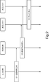
- FIG. 2 is a sequence diagram showing an example of the operation of the transport system according to the embodiment.
- FIG. 3 is a diagram showing an example of a schematic configuration of a transport system according to the first embodiment.
- FIG. 4 is a diagram showing an example of a processing configuration of the transfer robot according to the first embodiment.
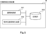
- FIG. 5 is a diagram showing an example of a processing configuration of the position information management device according to the first embodiment.
- FIG. 6 is a diagram showing an example of information in which the identifier of the camera device and the area photographed by the camera device are associated with each other.
- FIG. 7 is a diagram for explaining the operation of the object position information generation unit.
- FIG. 1 is a diagram for explaining an outline of one embodiment.
- FIG. 2 is a sequence diagram showing an example of the operation of the transport system according to the embodiment.
- FIG. 3 is a diagram showing an example of a schematic configuration of a transport system according to the first embodiment.
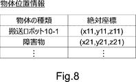
- FIG. 8 is a diagram showing an example of object position information transmitted from the position information management device.
- FIG. 9 is a diagram showing an example of a processing configuration of the transport planning apparatus according to the first embodiment.
- FIG. 10 is a diagram showing an example of a screen displayed by the transport plan information generation unit.
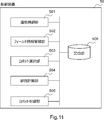
- FIG. 11 is a diagram showing an example of a processing configuration (processing module) of the control device according to the first embodiment.
- FIG. 12 is a diagram showing an example of the field configuration.
- FIG. 13 is a diagram showing an example of field configuration information.
- FIG. 14 is a diagram showing an example of link configuration information.
- FIG. 15 is a diagram showing an example of field management information.
- FIG. 16 is a diagram showing an example of robot management information.
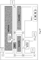
- FIG. 17 is a diagram for explaining recalculation by the route calculation unit.
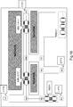
- FIG. 18 is a diagram for explaining recalculation by the route calculation unit.
- FIG. 19 is a sequence diagram showing an example of the operation of the transport system according to the first embodiment.
- FIG. 20 is a diagram showing an example of the hardware configuration of the control device.
- the transfer system includes a first transfer robot 101, a second transfer robot 102, a generation device 103, and a control device 104 (see FIG. 1).
- the first transfer robot 101 and the second transfer robot 102 transfer articles.
- the generation device 103 generates the position information of the first transfer robot 101 and the position information of the second transfer robot 102.
- the control device 104 uses the position information of the first transfer robot 101 and the position information of the second transfer robot 102 to transfer the goods by the first transfer robot 101 and the second transfer robot 102. Is transmitted to the first transfer robot 101 and the second transfer robot 102.
- FIG. 2 summarizes the operations of the transport system according to the above embodiment.
- the generation device 103 generates the position information of the first transfer robot 101 and the position information of the second transfer robot 102 (step S1). Based on the position information, the control device 104 transmits control information for transporting the goods by the first transport robot 101 and the second transport robot 102 to the first transport robot 101 and the second transport robot 102. (Step S2). The first transfer robot 101 and the second transfer robot 102 transfer the article based on the received control information (step S3).
- two transfer robots cooperate to move (convey) an article. Therefore, it can be adapted to a wide variety of goods carried into distribution warehouses and the like. For example, when two transfer robots sandwich and move an article, the two transfer robots can convey the article regardless of the shape of the article or the like. Further, the control device 104 can control these transfer robots in consideration of not only the situation of the two transfer robots but also the surrounding environment and the like. Therefore, for example, even if an obstacle or the like exists around the transfer robot (on the path of the transfer robot), the control device 104 can execute the control to avoid the obstacle.
- FIG. 3 is a diagram showing an example of a schematic configuration of a transport system according to the first embodiment.
- the transfer system includes a plurality of transfer robots 10-1 to 10-4, a plurality of camera devices 20-1 to 20-3, a position information management device 30, a transfer planning device 40, and the like.
- the control device 50 and the like are included.
- transfer robot 10 In the following description, if there is no particular reason for distinguishing the transfer robots 10-1 to 10-4, it is simply referred to as "transfer robot 10". The same applies to other configurations.
- the configuration shown in FIG. 3 is an example, and is not intended to limit the number of transfer robots 10 and the like included in the transfer system.
- the transfer robot 10 is a cooperative transfer robot that transfers the article 60 in cooperation with other robots. Specifically, the transfer robot 10 sandwiches the article 60 from opposite directions and moves the article 60 in the sandwiched state to convey the article 60.
- the transfer robot 10 is configured to be able to communicate with the control device 50, and moves based on a control command (control information) from the control device 50.
- the article 60 is fixed to a trolley with wheels. Therefore, when the two transfer robots 10 lightly sandwich the article 60 and move, the article 60 also moves.
- the transfer robot 10 can move independently, and makes a pair with an arbitrary transfer robot 10 to transfer the article 60.
- the transfer robot 10-1 and the transfer robot 10-2 form a pair
- the transfer robot 10-3 and the transfer robot 10-4 form a pair.
- the transfer robot 10-1 and the transfer robot 10-3 may be paired to transfer the article 60.
- a pair consisting of two transfer robots 10 will be referred to as a transfer robot pair.
- the transfer robot 10 that does not transfer the article 60 stands by at a predetermined position in the field.
- FIG. 3 shows a transport robot pair that is transporting the article 60, there is also a transport robot 10 that is waiting at a predetermined position in a field (not shown in FIG. 3).
- the camera device 20 is a device that images the inside of the field.
- the camera device 20 includes, for example, a depth camera, a stereo camera, and the like.
- the depth camera is a camera capable of taking a depth image in which each pixel value of the image indicates the distance from the camera to the object.
- the stereo camera is a camera capable of measuring the depth direction (height direction) of the object by photographing the object from a plurality of different directions using two cameras.
- the camera device 20 is installed on a ceiling, a pillar, or the like. Each camera device 20 is arranged so that the inside of the field can be overlooked when the image data captured by all the camera devices 20 are integrated.
- Each camera device 20 is connected to the position information management device 30.
- the camera device 20 images the inside of the field at a predetermined interval (predetermined sampling cycle) and transmits the image data to the position information management device 30.
- the camera device 20 captures the situation in the field in real time, and transmits image data including the situation to the position information management device 30.
- the position information management device 30 is a device that manages the position of an object in a field (for example, a factory or a distribution warehouse).
- the position information management device 30 identifies an object located in the field based on the image data received from the camera device 20, and generates position information of the object. For example, in the example of FIG. 3, the position information management device 30 generates the position information of the transfer robot 10-1 and the position information of the transfer robot 10-2.
- the position information management device 30 analyzes the image data acquired from the camera device 20 including the depth camera and the like to perform an object in the field (for example, a transfer robot 10, an article 60, and other obstacles placed in the field). ) Is identified.
- an object that does not exist in the initial state of the field is treated as an "obstacle".
- the position information management device 30 generates position information regarding an object in the field.
- the position information management device 30 calculates the position (absolute position) of an object in a three-dimensional coordinate system (X-axis, Y-axis, Z-axis) with an arbitrary point (for example, an entrance / exit) in the field as the origin.
- the position information management device 30 transmits the calculated position information of the object (hereinafter, referred to as object position information) to the control device 50.
- the transport planning device 40 is a device that generates article transport plan information including information on the transport source and transport destination of the article 60 transported by the transport robot pair. Specifically, the transport planning device 40 provides an operation screen (GUI; Graphical User Interface) for specifying the article 60 to be transported by the worker and inputting the transport source and transport destination of the article 60. The transport planning device 40 generates the article transport plan information based on the information input by the GUI. The transport planning device 40 transmits the generated article transport plan information to the control device 50.
- GUI Graphical User Interface
- the control device 50 controls the transfer robot 10 by using the object position information acquired from the position information management device 30 and the article transfer plan information acquired from the transfer planning device 40.
- the control device 50 acquires the transfer plan information
- the control device 50 selects two transfer robots 10 from the transfer robots 10 waiting in the field.
- the control device 50 instructs the two selected transfer robots 10 to go to the transfer source described in the transfer plan information.
- the control device 50 transmits control commands (control information) to the two transfer robots 10 and remotely controls these robots so as to head toward the transfer source.
- Each of the two transfer robots 10 moves based on the control command from the control device 50, and when the contact of the article 60 is detected by the contact sensor or the like, the "article pinching completion notification" is transmitted to the control device 50.
- the control device 50 it is not necessary to transmit the article pinching completion notification from the transfer robot 10.
- two transfer robots 10 sandwich an object (article 60) after a predetermined time (for example, 30 seconds) has elapsed after each of the two transfer robots 10 has moved to a predetermined position. You may think that. That is, the control device 50 may transmit a control command (control information) after the elapse of the predetermined time.
- control device 50 When the control device 50 acquires the article sandwiching notification from each transfer robot 10, it transmits a control command to each of the two transfer robots 10, and the transfer robot pair is sent to the transfer destination described in the article transfer plan. Remotely control to move. At that time, the control device 50 performs the remote control so that the transfer robot pair moves to the transfer destination while sandwiching the article 60. For example, the control device 50 transmits a control command (control information) so that the two transfer robots 10 move while maintaining a distance between the two opposing transfer robots 10.
- FIG. 4 is a diagram showing an example of a processing configuration (processing module) of the transfer robot 10 according to the first embodiment.
- the transfer robot 10 includes a communication control unit 201, an actuator control unit 202, and a pinch detection unit 203.
- the communication control unit 201 is a means for controlling communication with the control device 50.
- the communication control unit 201 communicates with the control device 50 by using a wireless communication means such as a wireless LAN (Local Area Network), LTE (Long Term Evolution), or a network used in a specific area such as local 5G.
- a wireless communication means such as a wireless LAN (Local Area Network), LTE (Long Term Evolution), or a network used in a specific area such as local 5G.
- the actuator control unit 202 is a means for controlling an actuator composed of a motor or the like based on a control command (control information) received from the control device 50.
- the control device 50 transmits a control command including a motor rotation start, a motor rotation speed, a motor rotation stop, and the like to the transfer robot 10.
- the actuator control unit 202 controls the motor and the like according to the control command.
- the pinch detection unit 203 is a means for detecting that the article 60 is pinched with another pair of transfer robots 10.
- a "contact sensor” is installed on a surface that sandwiches an article.
- the pinch detection unit 203 monitors the output of the contact sensor and determines whether or not the sensor has detected contact with an object.
- the pinching detection unit 203 transmits an “article pinching completion notification” to the control device 50 via the communication control unit 201.
- FIG. 5 is a diagram showing an example of a processing configuration (processing module) of the position information management device 30 according to the first embodiment.
- the position information management device 30 includes a communication control unit 301, an object position information generation unit 302, and a storage unit 303.
- the communication control unit 301 is a means for controlling communication with other devices (for example, camera device 20, control device 50) connected by wire (for example, LAN, optical fiber, etc.) or wirelessly.
- devices for example, camera device 20, control device 50
- wire for example, LAN, optical fiber, etc.
- the object position information generation unit 302 is a means for generating the object position information described above.
- the object position information generation unit 302 generates the object position information based on the image data acquired from the camera device 20.
- the camera device 20 transmits image data to the position information management device 30 together with its own identifier (ID; Identifier).
- ID the identifier of the camera device 20. Since the camera device 20 is fixed to the ceiling or the like, the camera device 20 continuously transmits image data of a predetermined area in the field to the position information management device 30.
- the object position information generation unit 302 detects an object by, for example, the following method.
- the storage unit 303 stores information that associates the identifier of the camera device 20 with the area photographed by each camera device 20 (see FIG. 6). By referring to the corresponding information, the object position information generation unit 302 can grasp an image corresponding to which area in the field the acquired image data corresponds to.
- the storage unit 303 stores the initial image data of the area captured by each camera device 20.
- the initial image data is image data in which an object that does not exist in the initial state is not shown in the field.
- the object position information generation unit 302 compares the acquired image data with the corresponding initial image data, and if there is a difference, determines that the image data includes the object to be detected.
- the object to be detected by the object position information generation unit 302 includes the transfer robot 10, the article 60, an obstacle placed in the passage of the field, and the like.
- the storage unit 303 stores an initial image as shown on the left side of FIG. 7.
- the image shown on the right side of FIG. 7 is an image acquired from the camera device 20.
- the object position information generation unit 302 calculates the difference between the two image data and detects the object included in the acquired image on the right side.
- the initial image data stored in the storage unit 303 is updated.
- the initial image data is updated when the layout of a factory or the like is changed.
- the object discrimination by the object position information generation unit 302 is not limited to the method using the initial image data.
- the object position information generation unit 302 calculates the coordinates of an object (obstacle) and detects that the object exists on the passage (on the link) based on the coordinates of the object and the normal coordinate information of the field. You may.
- the object position information generation unit 302 When the object position information generation unit 302 detects an object, it approximates the object to, for example, a rectangular shape, and calculates the coordinates of the four points. Specifically, the object position information generation unit 302 uses the relative coordinates (X coordinate, Y coordinate) of the object with respect to the absolute coordinates of the reference point based on the number of pixels from the reference point (for example, the lower left of the image) to the object in the image data. ) Is calculated. At that time, the object position information generation unit 302 calculates the relative coordinates of the object based on the information (resolution of the image sensor, etc.) of the camera device 20 that has acquired the image data.
- the absolute coordinates of the reference point of the acquired image data are known in advance.
- the object position information generation unit 302 calculates the absolute coordinates (X, Y coordinates) in the field of the object by adding the relative coordinates of the object calculated above to the absolute coordinates of the reference point. Further, when the image data is captured by the depth camera, the object position information generation unit 302 reads out the pixel values corresponding to the calculated X and Y coordinates to obtain the Z coordinate (height) of the object. ).
- the object position information generation unit 302 calculates the absolute positions of the four points forming the object by executing such processing on the four corners of the object.
- the object position information generation unit 302 determines the type of the object included in the acquired image.
- the object position information generation unit 302 calculates the size of the object detected from the absolute coordinates of the above four points.
- the object position information generation unit 302 may determine the type of the object based on the calculated size. For example, since the size of the transfer robot 10 is known in advance, if the size of the object and the size of the transfer robot 10 match, the object position information generation unit 302 determines that the detected object is the transfer robot 10. On the other hand, when the size of the detected object and the size of the transfer robot 10 do not match, the object position information generation unit 302 determines that the detected object is an obstacle.
- the method of determining whether or not the robot is a transfer robot based on the size of the object is an example, and other directions can be used.
- the transfer robot 10 is detected by attaching a marker having an identification function such as a QR code (registered trademark) or an AR (Augmented Reality) marker to the transfer robot 10 and reading the marker by the object position information generation unit 302. May be good.
- a marker is attached to the transfer robot 10, and it will be described that the detected object is the transfer robot 10 and that the transfer robot 10 can be identified.
- the transfer robot 10 is identified.
- the object position information generation unit 302 can identify the transfer robot 10 by a signal or the like from the transfer robot 10 without giving identification information (for example, characters or patterns) to the outside of the transfer robot 10.
- the object position information generation unit 302 may determine that the object sandwiched between the two transfer robots 10 is the article 60.
- the object position information generation unit 302 transmits the detected object type (transfer robot 10, obstacle, etc.) and its absolute position to the control device 50.
- the absolute position of the object may be the absolute coordinates of the four points forming the calculated object, or may be the absolute coordinates of one point representing the object (for example, the center of the object).
- FIG. 8 is a diagram showing an example of object position information transmitted from the position information management device 30. As shown in FIG. 8, when a plurality of objects are detected from the image data, the object position information regarding these objects may be collectively transmitted to the control device 50. In this way, the position information management device 30 generates the position information of the object including the transfer robot 10, and transmits the generated position information to the control device 50.
- FIG. 9 is a diagram showing an example of a processing configuration (processing module) of the transport planning device 40 according to the first embodiment.
- the transfer planning device 40 includes a communication control unit 401, a transfer plan information generation unit 402, a display unit 403, and a storage unit 404.
- the communication control unit 401 is a means for controlling communication with other devices, like the communication control unit 301 of the position information management device 30.
- the transport plan information generation unit 402 is a means for generating the above-mentioned goods transport plan information.
- the transport plan information generation unit 402 identifies the article 60 to be transported by the worker, and generates information on the GUI for inputting the transport source and transport destination of the article 60.
- the transport plan information generation unit 402 delivers the generated GUI information to the display unit 403.
- the display unit 403 displays the GUI information on a liquid crystal display or the like.
- the transport plan information generation unit 402 may generate information for displaying the GUI on a terminal used by the worker, and transmit the generated information to the terminal.
- the transport plan information generation unit 402 displays, for example, a screen as shown in FIG.
- the transport plan information generation unit 402 transmits the information input by the operator according to the screen as shown in FIG. 10 to the control device 50.
- the transport plan information generation unit 402 includes information for specifying the article 60 to be transported (for example, article name, serial number, etc.), a place where the article 60 is placed (transport source), and a transport destination of the article 60. Is associated with and transmitted to the control device 50 as the article transportation plan information.
- the transport plan information generation unit 402 may convert the name in the field input by the operator into the absolute coordinates in the field, and transmit the converted absolute coordinates to the control device 50.
- FIG. 11 is a diagram showing an example of a processing configuration (processing module) of the control device 50 according to the first embodiment.
- the control device 50 includes a communication control unit 501, a field information management unit 502, a robot selection unit 503, a route calculation unit 504, a robot control unit 505, and a storage unit 506. It is composed.
- the communication control unit 501 controls communication with other devices in the same manner as the communication control unit 401 and the like of the transfer planning device 40.
- the communication control unit 501 acquires the object position information from the position information management device 30 and acquires the article transportation plan information from the transfer planning device 40, the communication control unit 501 stores these information in the storage unit 506.
- the field information management unit 502 is a means for managing field map information, link information, and the like.
- the storage unit 506 stores field configuration information indicating the field configuration.
- the start point, end point, branch point, and the like of the passage through which the transfer robot 10 can pass are regarded as nodes.
- the field configuration information defines the absolute coordinates of the node.
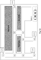
- the field configuration is as shown in FIG.
- the absolute coordinates of the node N1 and the node N2 are defined by the field configuration information (see FIG. 13).
- the storage unit 506 stores link information indicating the connection relationship of the nodes. For example, in the example of FIG. 12, the link information as shown in FIG. 14 is stored.
- the storage unit 506 stores field management information for managing the current state of the field.
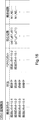
- the field management information includes the distance between the links, the presence / absence of the transfer robot 10, and the presence / absence of obstacles.
- FIG. 15 is a diagram showing an example of field management information.
- the absolute coordinates of the transfer robot 10 are written in the transfer robot field.
- the absolute coordinates of the obstacle are written in the obstacle field.
- the initial values of the transfer robot field and the obstacle field are "no transfer robot" and "no obstacle”.
- the distance between the nodes constituting each link can be calculated in advance. The distance between the nodes is calculated before system operation and written to the field management information.
- the field information management unit 502 updates the field management information based on the object position information received from the position information management device 30. Specifically, the field information management unit 502 specifies the type of object (transfer robot, obstacle) included in the acquired object position information. The field information management unit 502 refers to the field configuration information and the link configuration information stored in the storage unit 506, and identifies the link in which the specified object exists. The field information management unit 502 updates the transfer robot field and the obstacle field corresponding to the specified link based on the type of the specified object (transfer robot, obstacle) and its absolute coordinates.
- the field information management unit 502 updates the field management information every time the object position information is acquired from the position information management device 30. Therefore, by referring to the field management information, the current state in the field can be grasped. If an obstacle is placed in the field, the existence of the obstacle can be immediately found by referring to the field management information. Further, the position of the transfer robot 10 operating in the field is also known from the field management information.
- the field information management unit 502 updates the current position field of the robot management information described later based on the absolute coordinates of the transfer robot 10 read from the object position information.
- the robot selection unit 503 is a means for selecting the transfer robot 10 that conveys the article 60. Specifically, when the robot selection unit 503 acquires the article transfer plan information from the transfer planning device 40, the robot selection unit 503 selects the transfer robot 10 for transporting the article 60 described in the information. The robot selection unit 503 selects two transfer robots 10 from a plurality of transfer robots 10 waiting in the standby area.
- the robot selection unit 503 may select two transfer robots 10 based on any criteria. For example, the robot selection unit 503 may select the transfer robot 10 closest to the transfer source described in the transfer plan information, or may select the transfer robot 10 in ascending order of operating time. Alternatively, if the remaining battery level can be obtained from the transfer robot 10, the robot selection unit 503 may select the robots having the highest remaining battery level in order. Alternatively, the robot selection unit 503 may select a transfer robot 10 having special specifications according to the article 60. For example, when the article 60 is extremely heavy, the transport robot 10 for transporting heavy objects may be selected, and when the article 60 is lightweight, the transport robot 10 for transporting lightweight objects may be selected.
- the robot selection unit 503 notifies the route calculation unit 504 and the robot control unit 505 of the selected transfer robot 10 (transfer robot pair). Further, the robot selection unit 503 reflects the information about the selected transfer robot 10 in the robot management information. The details of the robot management information will be described later.
- the route calculation unit 504 is a means for calculating the route for the transport robot pair to transport the article 60 from the transport source to the transport destination based on the article transport plan information generated by the transport planning device 40. For example, when “Area A" is described as the transport source and "Area D" is described as the transport destination in the article transport plan information, the route from the lower left to the middle upper right of FIG. 12 is calculated.
- the storage unit 506 stores the relationship between each area and the corresponding node in association with each other. For example, information that the area B corresponds to the node N4 is stored in the storage unit 506.
- the route calculation unit 504 calculates the route for transporting the article 60 from the transport source to the transport destination by using a route search algorithm such as the Dijkstra method or the Bellman-Ford method. For example, in the above example, a route via nodes N1, N2, N3, N8, N9 and a route via nodes N1, N2, N6, N7, N8 are calculated.
- a route search algorithm such as the Dijkstra method or the Bellman-Ford method.
- the route calculation unit 504 refers to the field management information at the time of the route calculation.
- the route calculation unit 504 treats the distance between the nodes as the cost of the link and calculates the transport route, for example. At that time, the route calculation unit 504 determines that the link with an obstacle is impassable, treats the cost of the link as infinite, and calculates the transport route.
- the route calculation unit 504 does not include the link with the transfer robot 10 in the cost. This is because the transfer robot 10 moves with the passage of time.
- the route calculation unit 504 manages the calculated route in association with the transfer robot 10 that uses the route. Specifically, the route calculation unit 504 updates the robot management information stored in the storage unit 506.
- FIG. 16 is a diagram showing an example of robot management information.
- the identifier of the transfer robot 10 the state of each robot (during transfer, waiting), the information of the transfer robot 10 to be paired, the current position, and the information about the route used by the transfer robot 10 are associated and managed.
- any ID such as the MAC (Media Access Control) address and the name (transfer robot No. 1 and No. 2) assigned to each transfer robot 10 can be used.
- the state field is updated by the robot control unit 505.
- the fields related to the paired robots are updated by the robot selection unit 503.
- the current position field is updated by the field information management unit 502.
- the transport route field is updated by the route calculation unit 504.
- the robot control unit 505 is a means for controlling the transfer robot 10.
- the robot control unit 505 provides control information for transporting the article 60 by the transport robot pair based on the position information of the transport robot 10 and the position information of another transport robot 10 paired with the transfer robot 10. Send to 10. That is, the robot control unit 505 controls the transfer robot 10 by transmitting a control command (control information) to the transfer robot 10.
- control command control information
- all the control commands may be transmitted at once so that the transfer robot pair can move from the transfer source to the transfer destination, or the transfer robot pair may send the control command.
- the control commands may be transmitted in order according to the position and the like.
- the robot control unit 505 needs information on the orientation of the transfer robot 10 when controlling the transfer robot 10.
- a gyro sensor or the like is attached to the transfer robot 10, and the robot control unit 505 may acquire information regarding the orientation from the transfer robot 10.
- the orientation when arranging the transfer robot 10 in the standby area may be determined in advance, and the orientation of the transfer robot 10 may be estimated based on a control command transmitted from the robot control unit 505 to the transfer robot 10.
- the robot control unit 505 When the robot control unit 505 receives the notification of robot selection from the robot selection unit 503, the robot control unit 505 controls the selected transfer robot 10 to move to the transfer source described in the article transfer plan. Since the control related to the initial movement can be the same as the control when the transfer robot 10 moves from the transfer source to the transfer destination, the details thereof will be omitted.
- the robot control unit 505 confirms whether or not the article 60 is placed at the transfer source. Any method can be used for the confirmation. For example, when the worker places the article 60 at the transport source, the above confirmation may be made by the worker pressing a button connected to the control device 50. Alternatively, a sensor (infrared sensor, camera, weight sensor, etc.) may be installed in the area serving as the transport source, and the article 60 may be confirmed using the sensor. That is, the robot control unit 505 may recognize that the article 60 has been installed at the transport source based on the output of the sensor.
- a sensor infrared sensor, camera, weight sensor, etc.
- the robot control unit 505 may confirm whether or not the article 60 placed at the transport source is the article 60 input by the article transport plan information. For example, consider a case where a camera is installed near the transport source and the article 60 is provided with a marker (AR marker or the like) for identifying the article 60. In this case, the robot control unit 505 refers to the information associated with the marker and the article 60, and confirms that the article 60 placed at the transport source matches the article 60 input in the article transport plan information. May be good.
- the robot control unit 505 may determine that the article 60 placed by the operator at the transport source is the article 60 described in the article transport plan information, and may omit the above confirmation. That is, the robot control unit 505 may trust the operator and omit the confirmation of the article 60.
- the robot control unit 505 controls the two transfer robots 10 to sandwich the article 60 by transmitting a control command to the transfer robot 10. Specifically, the robot control unit 505 moves these robots so that the two transfer robots 10 face each other over the article 60, and moves the robots so that the distance between the robots becomes narrow.
- the control device 50 When each of the two transfer robots 10 succeeds in pinching the article 60, the control device 50 is notified of the completion of pinching the article.
- the robot control unit 505 receives the above notification from each of the two transfer robots 10, the robot control unit 505 starts the transfer by the two transfer robots 10. Specifically, the robot control unit 505 generates a control command so that the transfer robot pair sandwiching the article 60 moves on the path calculated as the transfer path of the transfer robot pair, and causes each transfer robot 10 to move. Send.
- the control of the two transfer robots 10 by the robot control unit 505 can be realized by the description of Reference 1 below. Further, details regarding the mechanism of the transfer robot 10 are also described in the document.
- the robot control unit 505 treats one of the two transfer robots 10 as a "leader transfer robot” and the other one as a “successor transfer robot”. Then, the robot control unit 505 acquires the current position of the leading transfer robot 10 among the transfer robots 10 described in the robot management information. Next, the robot control unit 505 determines the position where the leading transfer robot 10 reaches.
- the robot control unit 505 takes time and speed to rotate the motor of each transfer robot 10 according to the distance between the current position of the transfer robot 10 as a leader and the calculated arrival position. Calculate. At that time, the robot control unit 505 generates a control command so that the motor rotation speeds of the transfer robots 10 are the same.
- the robot control unit 505 When rotating the transport robot pair, the robot control unit 505 uses a model of circular motion that draws a curve due to the speed difference between the left and right wheels. Specifically, the robot control unit 505 calculates the input speed to the left and right wheels for reaching the target position from the current position in a circular orbit based on the target position and the position and orientation of the robot. The robot control unit 505 uses the calculated input speed as it is for the leading role transfer robot 10, and generates a control command to be transmitted to the leading role transfer robot 10 based on the calculated input speed. ..
- the robot control unit 505 determines the speed correction value in the front-rear direction based on the inter-robot distance (distance between the plates sandwiching the article 60 by each transport robot) and the left and right wheels based on the rotation angle with respect to the transport robot 10 as the succeeding robot. Calculate the offset correction value.
- the robot control unit 505 generates a control command to be transmitted to the succeeding transfer robot 10 based on these correction values (speed correction value, offset correction value).
- the robot control unit 505 controls the transfer robot pair so as to place the article 60 at the transfer destination. Specifically, the robot control unit 505 completes the transfer of the article 60 by controlling the distance between the two transfer robots 10 to be long.
- the basic control of the robot control unit 505 is as described above.
- the control of the robot control unit 505 is a control when there is no other transfer robot 10 in the field and no obstacle is placed on the transfer path during transfer. However, in the actual field, another transfer robot 10 may use its own transfer path, or an obstacle may be placed on the initially calculated transfer path.
- the robot control unit 505 controls two transfer robots 10 so that the article 60 is correctly conveyed to the transfer destination even in the above situation.
- the robot control unit 505 refers to the latest field management information and robot management information, and determines whether or not it is necessary to recalculate the transfer route for the transfer robot 10 being transferred. Specifically, the robot control unit 505 refers to the latest field management information, and whether or not an object (obstacle or transfer robot pair) exists in the link constituting the transfer path of the transfer robot pair during transfer. To judge. If it is determined that an object exists as a result of the determination, the robot control unit 505 recalculates the transfer route to the route calculation unit 504 with the current position of the transfer robot pair as the start node and the transfer destination as the end node. Instruct.
- the route calculation unit 504 recalculates the transport route in response to the above instruction. At that time, since the absolute coordinates of the object (obstacle or transport robot pair) are described in the obstacle field of the link included in the previously calculated transport route in the latest link management information, the route calculation unit 504 Calculates the transport route to the transport destination while avoiding a certain link of the object. The recalculated transfer route is reflected in the transfer route field of the robot management information.
- the robot control unit 505 may control the two transfer robots 10 based on the reflected transfer path.
- the robot control unit 505 controls the transfer robot pair so as to pass through the above path.
- an object an obstacle is illustrated in FIG. 17
- the robot control unit 505 grasps the existence of the object from the latest field management information, and instructs the route calculation unit 504 to recalculate the transport route.
- the route as shown by the dotted line in FIG. 17 is recalculated.
- the control device 50 calculates (recalculates) the path for transporting the article 60 in consideration of the existence of the object. ).
- control device 50 may change the control according to the type of the object placed in the field. For example, if the object existing in the field is an "obstacle", the control device 50 recalculates the path described above. On the other hand, if the object existing in the field is a "transfer robot pair", the control device 50 may recalculate the route according to the distance between the transfer robot pairs.
- Obstacles placed on the transport route may not be moved in a short time. Therefore, when the robot control unit 505 detects that an obstacle is placed on the transport route, it instructs the route calculation unit 504 to recalculate the transport route. On the other hand, even if the transfer robot 10 is present on the transfer path, the robot is expected to move in a short time, so that there is a possibility that the transfer robot pair does not become an obstacle (an obstacle that blocks the way) during transfer. is there.
- the robot control unit 505 instructs the route calculation unit 504 to recalculate the transfer path if the distance between the two transfer robot pairs is short.
- the robot control unit 505 refers to the latest field management information, and if the transfer robot 10 exists on the transfer path of the transfer robot pair during transfer, the current position of the transfer robot pair during transfer and the above The distance between the transfer robots 10 existing on the transfer path is calculated.
- the robot control unit 505 executes threshold processing for the distance, and instructs the route calculation unit 504 to recalculate the transport route according to the result.
- the robot control unit 505 controls the transport robot pair so as to move the latest transport route.
- FIG. 19 is a sequence diagram showing an example of the operation of the transport system according to the first embodiment.
- the camera device 20 transmits the captured image data to the position information management device 30 (step S01).
- the position information management device 30 analyzes the acquired image data and attempts to detect an object. When the object is detected from the field, the position information management device 30 generates the object position information (step S02). The position information management device 30 transmits the generated object position information to the control device 50 (step S03).
- the camera device 20 and the position information management device 30 repeat the operations of steps S01 to S03 in a predetermined cycle.
- the control device 50 can grasp the situation in the field in real time.
- control device 50 acquires the object position information
- the control device 50 updates the field management information (step S04).
- the control device 50 receives the article transport plan information from the transport planning device 40 (step S05).
- the control device 50 selects the transfer robot 10 that conveys the article 60 (step S06).
- the control device 50 calculates the transport path of the transport robot pair based on the article transport plan information (step S07).
- the control device 50 generates a control command so that the transfer robot pair moves on the transfer path calculated above, and transmits the control command to the transfer robot pair (step S08).
- Each of the transfer robots 10 receives the control command and executes the control command (steps S09 and S10).
- the transfer robot 10 executes the control command, it transmits an acknowledgment (ACK).
- control device 50 and the transfer robot pair convey the article 60 to the transfer destination by repeating the above steps S08 to S09.
- the control device 50 transmits control information for the two transfer robots 10 to sandwich and convey the article 60 to these transfer robots 10. At that time, the control device 50 calculates a route for transporting the article 60 based on the position information of an object (transfer robot 10, an obstacle) existing in the field, and uses the calculated route to perform the article 60.
- the control information for transporting is transmitted to the transporting robot 10. That is, in the transfer system according to the first embodiment, position information of the transfer robot 10 and the like is generated, and the transfer robot 10 is controlled based on the position information. Therefore, the transfer robot 10 can be controlled even in an environment (complex environment) in which a magnetic tape or the like is unnecessary and SLAM does not function.
- the two transport robots cooperate to transport the article 60, the labor of the operator for transshipping the article 60 is not required, and it is possible to cope with a wide variety of shapes of the article 60. Or something like that. That is, since the two transfer robots 10 form a pair and move while sandwiching the article 60, the article 60 can be moved regardless of the shape of the article 60 or the like. Further, even when the article 60 is mounted on the trolley, the pair of the transfer robots 10 can move the article 60 together with the trolley, so that the operator does not need to replace the article 60. .. Further, since the two transport robots cooperate to transport (transport) the article 60, it is not necessary to attach a traction device or the like to the article 60 or the trolley.
- control device 50 can be implemented as a cloud server on a network (for example, a wireless communication network such as the Internet or LTE), and realizes coordinated control of the transfer robot 10 while giving a bird's-eye view of the entire field. Further, since the transfer robot 10 is centrally controlled by the control device 50, a sensor (expensive sensor) for monitoring the periphery of the transfer robot 10 is unnecessary, and the price of the transfer robot 10 can be reduced.
- a sensor expensive sensor
- the transport instruction of the article 60 is generated by the transport planning device 40, and the user can input location information such as a destination via the device, so that the article 60 is intuitively, easily understood, and efficiently transported. Is possible.
- FIG. 20 is a diagram showing an example of the hardware configuration of the control device 50.
- the control device 50 can be configured by an information processing device (so-called computer), and includes the configuration illustrated in FIG. 20.
- the control device 50 includes a processor 311, a memory 312, an input / output interface 313, a communication interface 314, and the like.
- the components such as the processor 311 are connected by an internal bus or the like so that they can communicate with each other.
- control device 50 may include hardware (not shown), or may not include an input / output interface 313 if necessary.
- number of processors 311 and the like included in the control device 50 is not limited to the example of FIG. 20, and for example, a plurality of processors 311 may be included in the control device 50.
- the processor 311 is a programmable device such as a CPU (Central Processing Unit), an MPU (Micro Processing Unit), and a DSP (Digital Signal Processor). Alternatively, the processor 311 may be a device such as an FPGA (Field Programmable Gate Array) or an ASIC (Application Specific Integrated Circuit). The processor 311 executes various programs including an operating system (OS; Operating System).
- OS Operating System
- the memory 312 is a RAM (RandomAccessMemory), a ROM (ReadOnlyMemory), an HDD (HardDiskDrive), an SSD (SolidStateDrive), or the like.
- the memory 312 stores an OS program, an application program, and various data.
- the input / output interface 313 is an interface of a display device or an input device (not shown).
- the display device is, for example, a liquid crystal display or the like.
- the input device is, for example, a device that accepts user operations such as a keyboard and a mouse.
- the communication interface 314 is a circuit, module, or the like that communicates with another device.
- the communication interface 314 includes a NIC (Network Interface Card), a wireless communication circuit, and the like.
- NIC Network Interface Card
- the function of the control device 50 is realized by various processing modules.
- the processing module is realized, for example, by the processor 311 executing a program stored in the memory 312.
- the program can also be recorded on a computer-readable storage medium.
- the storage medium can be a non-transient such as a semiconductor memory, a hard disk, a magnetic recording medium, or an optical recording medium. That is, the present invention can also be embodied as a computer program product.
- the program can be downloaded via a network or updated using a storage medium in which the program is stored.
- the processing module may be realized by a semiconductor chip.
- the position information management device 30, the transfer planning device 40, and the like can also be configured by an information processing device like the control device 50, and the basic hardware configuration thereof is not different from that of the control device 50, so the description thereof is omitted. To do.
- the function of the position information management device 30 may be realized by the control device 50.
- the position information management device 30 may execute a process related to determining the position of an object, and the control device 50 may determine the type of the object.
- the location information management device 30 may be installed inside the field, and the control device 50 may be mounted on a server on the network. That is, the transport system disclosed in the present application may be realized as an edge cloud system.
- the transfer path of the other transfer robot pair when calculating the transfer path of the transfer robot pair, the transfer path of the other transfer robot pair is not considered, but the transfer path is calculated in consideration of the transfer path of the other transfer robot pair. May be good.
- the route calculation unit 504 may calculate the route with the cost of the link (link to be used) used by the other transfer robot pair infinite.
- the route calculation unit 504 may count the number used as the transport route by the transport robot pair for each link, and calculate the transport route using the counted value as the congestion degree of the link.
- the route calculation unit 504 may treat the degree of congestion as the cost of the link and calculate the transport route so as to avoid the link having a high degree of congestion.
- a camera capable of detecting the height of the object for example, a depth camera
- a normal camera may be used.
- an infrared sensor or a distance sensor may be used as a sensor for detecting the position of an object.
- the code may include the identification information of the article 60, and the transfer robot 10 may read the information.
- the transfer robot 10 may compare the read identification information with the identification information of the article 60 instructed to be conveyed by the control device 50, and decide whether or not to convey the article 60 according to the result. ..
- the computer By installing the article transport program in the storage unit of the computer, the computer can function as the control device 50. Further, by causing the computer to execute the article transport program, the article transport method can be executed by the computer.
- the present invention is suitably applicable to the transportation of goods such as factories and distribution warehouses.
- [Appendix 1] The first and second transport robots (10) that transport goods, and Generation devices (30, 103) that generate the position information of the first transfer robot (10) and the position information of the second transfer robot (10). Control for transporting the article by the first and second transport robots (10) based on the position information of the first transport robot (10) and the position information of the second transport robot (10). A control device (50, 104) that transmits information to the first and second transfer robots (10), and Including the transport system.
- [Appendix 2] Further including a transport planning apparatus (40) for generating transport plan information, including information on the transport source and destination of the goods transported by the first and second transport robots (10).
- the control device (50, 104) is a route for the first and second transfer robots (10) to transfer the article from the transfer source to the transfer destination based on the generated article transfer plan information.
- the control device (50, 104) identifies a route for transporting the article based on the position information of an obstacle in the field for transporting the article, and transports the article along the specified route.
- the transfer system according to Appendix 1 or 2 wherein the control information of the above is transmitted to the first and second transfer robots (10).
- the transport system according to Appendix 3, wherein the control device (50, 104) calculates a route for transporting the article in consideration of the obstacle when the obstacle is present on the specified route.
- [Appendix 7] It is connected to a generator (30, 103) that generates the position information of the first transfer robot (10) and the position information of the second transfer robot (10) that conveys the goods. Control for transporting the article by the first and second transport robots (10) based on the position information of the first transport robot (10) and the position information of the second transport robot (10). Control devices (50, 104) that transmit information to the first and second transfer robots (10).
- [Appendix 8] Connected to a transport planning device (40) that generates transport plan information, including information about the transport source and destination of the goods transported by the first and second transport robots (10).
- [Appendix 9] Based on the position information of the obstacle in the field for transporting the article, the route for transporting the article is specified, and the control information for transporting the article along the specified route is the first and second.
- [Appendix 14] A step of generating transfer plan information including information on a transfer source and a transfer destination of the goods transported by the first and second transfer robots (10), and A step of specifying a route for the first and second transport robots (10) to transport the goods from the transport source to the transport destination based on the generated article transport plan information.
- [Appendix 15] A step of identifying a route for transporting the article based on the position information of an obstacle in the field for transporting the article, and A step of transmitting control information for transporting the article by the specified route to the first and second transport robots (10), and The transport method according to Appendix 13 or 14, further comprising.
- [Appendix 16] The transport method according to Appendix 15, wherein the step of specifying the route calculates a route for transporting the article in consideration of the obstacle when the obstacle is present on the specified route.
- [Appendix 17] In the step of specifying the route, when a third transfer robot (10) different from the first and second transfer robots (10) exists on the specified route, the first and second transfer robots (10) are present.
- Position information management device 40 Transfer planning device 50, 104 Control device 60, 60-1, 60-2 Article 101 1st Transfer robot 102 Second transfer robot 103 Generation device 201, 301, 401, 501 Communication control unit 202 Actuator control unit 203 Pinching detection unit 302 Object position information generation unit 303, 404, 506 Storage unit 311 Processor 312 Memory 313 Input / output interface 314 Communication interface 402 Transport plan information generation unit 403 Display unit 502 Field information management unit 503 Robot selection unit 504 Route calculation unit 505 Robot control unit
Landscapes
- Engineering & Computer Science (AREA)
- Aviation & Aerospace Engineering (AREA)
- Radar, Positioning & Navigation (AREA)
- Remote Sensing (AREA)
- Physics & Mathematics (AREA)
- General Physics & Mathematics (AREA)
- Automation & Control Theory (AREA)
- Control Of Position, Course, Altitude, Or Attitude Of Moving Bodies (AREA)
- Warehouses Or Storage Devices (AREA)
- Manipulator (AREA)
Priority Applications (5)
| Application Number | Priority Date | Filing Date | Title |
|---|---|---|---|
| US17/633,697 US20220317704A1 (en) | 2019-08-26 | 2020-07-21 | Transport system, control apparatus, transport method, and program |
| EP20856106.8A EP4024152B1 (en) | 2019-08-26 | 2020-07-21 | Transport system, control device, transport method, and program |
| JP2021542634A JP7318713B2 (ja) | 2019-08-26 | 2020-07-21 | 搬送システム、制御装置、搬送方法及びプログラム |
| JP2023113381A JP7559883B2 (ja) | 2019-08-26 | 2023-07-11 | 搬送システム、制御装置、搬送方法及びプログラム |
| JP2024153871A JP7740470B2 (ja) | 2019-08-26 | 2024-09-06 | 搬送システム、制御装置、搬送方法及びプログラム |
Applications Claiming Priority (2)
| Application Number | Priority Date | Filing Date | Title |
|---|---|---|---|
| JP2019153964 | 2019-08-26 | ||
| JP2019-153964 | 2019-08-26 |
Publications (1)
| Publication Number | Publication Date |
|---|---|
| WO2021039210A1 true WO2021039210A1 (ja) | 2021-03-04 |
Family
ID=74684715
Family Applications (1)
| Application Number | Title | Priority Date | Filing Date |
|---|---|---|---|
| PCT/JP2020/028190 Ceased WO2021039210A1 (ja) | 2019-08-26 | 2020-07-21 | 搬送システム、制御装置、搬送方法及びプログラム |
Country Status (4)
| Country | Link |
|---|---|
| US (1) | US20220317704A1 (https=) |
| EP (1) | EP4024152B1 (https=) |
| JP (3) | JP7318713B2 (https=) |
| WO (1) | WO2021039210A1 (https=) |
Cited By (3)
| Publication number | Priority date | Publication date | Assignee | Title |
|---|---|---|---|---|
| CN114326618A (zh) * | 2021-12-24 | 2022-04-12 | 牧野机床(中国)有限公司 | 工件位置的控制方法、装置、计算机设备以及存储介质 |
| JP2023036418A (ja) * | 2021-09-02 | 2023-03-14 | 東芝テック株式会社 | 移動指示装置およびプログラム |
| WO2023132101A1 (ja) * | 2022-01-07 | 2023-07-13 | 村田機械株式会社 | 搬送システム |
Families Citing this family (2)
| Publication number | Priority date | Publication date | Assignee | Title |
|---|---|---|---|---|
| JP7251654B2 (ja) * | 2019-11-18 | 2023-04-04 | 日本電気株式会社 | 搬送装置、制御方法、及び、制御プログラム |
| CN116867716A (zh) * | 2021-03-09 | 2023-10-10 | 松下知识产权经营株式会社 | 货物搬送系统及搬送体 |
Citations (5)
| Publication number | Priority date | Publication date | Assignee | Title |
|---|---|---|---|---|
| JPH1029556A (ja) * | 1996-04-30 | 1998-02-03 | Fuji Electric Co Ltd | 搬送装置 |
| JP2011216007A (ja) * | 2010-04-01 | 2011-10-27 | Gen Inc | 搬送台車システム |
| JP2016224540A (ja) * | 2015-05-27 | 2016-12-28 | シャープ株式会社 | 移動体システム、制御装置及び移動体 |
| JP2018092393A (ja) * | 2016-12-05 | 2018-06-14 | 株式会社ディスコ | 自動搬送車コントロールシステム |
| JP2019153964A (ja) | 2018-03-05 | 2019-09-12 | アンリツ株式会社 | フレーム同期装置及びそれを備えた測定装置並びにフレーム同期方法及び測定方法 |
Family Cites Families (12)
| Publication number | Priority date | Publication date | Assignee | Title |
|---|---|---|---|---|
| JP3159649B2 (ja) * | 1996-06-07 | 2001-04-23 | 三菱電機株式会社 | 無人搬送車システム |
| JP2000339026A (ja) * | 1999-05-31 | 2000-12-08 | Mitsubishi Heavy Ind Ltd | 走行制御装置 |
| JP4329035B2 (ja) * | 2004-08-18 | 2009-09-09 | 株式会社ダイフク | 物品搬送装置 |
| JP4877520B2 (ja) * | 2007-06-26 | 2012-02-15 | 株式会社Ihi | 搬送ロボットとその動作制御方法並びに協調搬送システム及び方法 |
| JP6020265B2 (ja) * | 2012-04-11 | 2016-11-02 | 株式会社ダイフク | 物品搬送設備 |
| JP2015060336A (ja) * | 2013-09-18 | 2015-03-30 | 清水建設株式会社 | 床位置検出方法を用いた無人搬送車及び無人搬送システム |
| US9606544B2 (en) * | 2014-10-31 | 2017-03-28 | Clearpath Robotics, Inc. | System, computing device and method for unmanned vehicle fleet control |
| DE102014016900A1 (de) * | 2014-11-17 | 2016-05-19 | Eisenmann Se | Fördersystem zum Fördern von Gegenständen sowie Steuerungsverfahren hierfür |
| US10133276B1 (en) * | 2015-06-19 | 2018-11-20 | Amazon Technologies, Inc. | Object avoidance with object detection and classification |
| US20180330319A1 (en) * | 2017-05-10 | 2018-11-15 | Ping Liang | Autonomous vehicles for efficient transportation and delivery of packages |
| JP6951162B2 (ja) * | 2017-09-08 | 2021-10-20 | 株式会社東芝 | 搬送システム、搬送装置及び搬送方法 |
| US11150646B2 (en) * | 2019-01-22 | 2021-10-19 | Here Global B.V. | Delivery with swarming aerial vehicles |
-
2020
- 2020-07-21 WO PCT/JP2020/028190 patent/WO2021039210A1/ja not_active Ceased
- 2020-07-21 EP EP20856106.8A patent/EP4024152B1/en active Active
- 2020-07-21 US US17/633,697 patent/US20220317704A1/en not_active Abandoned
- 2020-07-21 JP JP2021542634A patent/JP7318713B2/ja active Active
-
2023
- 2023-07-11 JP JP2023113381A patent/JP7559883B2/ja active Active
-
2024
- 2024-09-06 JP JP2024153871A patent/JP7740470B2/ja active Active
Patent Citations (5)
| Publication number | Priority date | Publication date | Assignee | Title |
|---|---|---|---|---|
| JPH1029556A (ja) * | 1996-04-30 | 1998-02-03 | Fuji Electric Co Ltd | 搬送装置 |
| JP2011216007A (ja) * | 2010-04-01 | 2011-10-27 | Gen Inc | 搬送台車システム |
| JP2016224540A (ja) * | 2015-05-27 | 2016-12-28 | シャープ株式会社 | 移動体システム、制御装置及び移動体 |
| JP2018092393A (ja) * | 2016-12-05 | 2018-06-14 | 株式会社ディスコ | 自動搬送車コントロールシステム |
| JP2019153964A (ja) | 2018-03-05 | 2019-09-12 | アンリツ株式会社 | フレーム同期装置及びそれを備えた測定装置並びにフレーム同期方法及び測定方法 |
Cited By (5)
| Publication number | Priority date | Publication date | Assignee | Title |
|---|---|---|---|---|
| JP2023036418A (ja) * | 2021-09-02 | 2023-03-14 | 東芝テック株式会社 | 移動指示装置およびプログラム |
| CN114326618A (zh) * | 2021-12-24 | 2022-04-12 | 牧野机床(中国)有限公司 | 工件位置的控制方法、装置、计算机设备以及存储介质 |
| WO2023132101A1 (ja) * | 2022-01-07 | 2023-07-13 | 村田機械株式会社 | 搬送システム |
| JPWO2023132101A1 (https=) * | 2022-01-07 | 2023-07-13 | ||
| JP7811342B2 (ja) | 2022-01-07 | 2026-02-05 | 村田機械株式会社 | 搬送システム |
Also Published As
| Publication number | Publication date |
|---|---|
| JP7318713B2 (ja) | 2023-08-01 |
| JP2024164312A (ja) | 2024-11-26 |
| JP7740470B2 (ja) | 2025-09-17 |
| EP4024152A1 (en) | 2022-07-06 |
| JP7559883B2 (ja) | 2024-10-02 |
| JPWO2021039210A1 (https=) | 2021-03-04 |
| JP2023134605A (ja) | 2023-09-27 |
| EP4024152B1 (en) | 2025-02-19 |
| EP4024152A4 (en) | 2022-10-26 |
| US20220317704A1 (en) | 2022-10-06 |
Similar Documents
| Publication | Publication Date | Title |
|---|---|---|
| JP7318713B2 (ja) | 搬送システム、制御装置、搬送方法及びプログラム | |
| JP7416072B2 (ja) | 搬送システム、制御装置、及び搬送方法 | |
| US11016493B2 (en) | Planning robot stopping points to avoid collisions | |
| JP6531968B2 (ja) | 移動ロボットマニピュレータ | |
| ES2827192T3 (es) | Sistema de gestión de tareas para una flota de robots móviles autónomos | |
| KR102160968B1 (ko) | 자율주행 로봇 장치 및 자율 주행 방법 | |
| JP6956192B2 (ja) | ロボットアドホックネットワーク | |
| US10134293B2 (en) | Systems and methods for autonomous drone navigation | |
| CN113657565A (zh) | 机器人跨楼层移动方法、装置、机器人及云端服务器 | |
| US9881277B2 (en) | Wrist band haptic feedback system | |
| WO2019169643A1 (zh) | 行李运输方法、运输系统、机器人、终端设备及存储介质 | |
| US10628790B1 (en) | Automated floor expansion using an unmanned fiducial marker placement unit | |
| CN116075795A (zh) | 环境变更提案系统及环境变更提案程序 | |
| US20210123766A1 (en) | Travel control apparatus, mobile body, and operation system | |
| WO2023073780A1 (ja) | 学習データの生成装置および学習データの生成方法、並びに学習データを使用する機械学習装置および機械学習方法 | |
| JP2022125493A (ja) | 移動ロボット、搬送システム、方法、及びプログラム | |
| JP7563455B2 (ja) | 移動体制御システム、制御装置、及び、移動体制御方法 | |
| JP7501643B2 (ja) | 移動体制御システム、制御装置、及び、移動体制御方法 | |
| Mingyang et al. | Multi-robot cooperation for mixed depalletizing | |
| WO2026060354A1 (en) | Real-time location system enabled human-robot interaction |
Legal Events
| Date | Code | Title | Description |
|---|---|---|---|
| 121 | Ep: the epo has been informed by wipo that ep was designated in this application |
Ref document number: 20856106 Country of ref document: EP Kind code of ref document: A1 |
|
| ENP | Entry into the national phase |
Ref document number: 2021542634 Country of ref document: JP Kind code of ref document: A |
|
| NENP | Non-entry into the national phase |
Ref country code: DE |
|
| ENP | Entry into the national phase |
Ref document number: 2020856106 Country of ref document: EP Effective date: 20220328 |