WO2021038709A1 - Dispositif d'éclairage - Google Patents
Dispositif d'éclairage Download PDFInfo
- Publication number
- WO2021038709A1 WO2021038709A1 PCT/JP2019/033453 JP2019033453W WO2021038709A1 WO 2021038709 A1 WO2021038709 A1 WO 2021038709A1 JP 2019033453 W JP2019033453 W JP 2019033453W WO 2021038709 A1 WO2021038709 A1 WO 2021038709A1
- Authority
- WO
- WIPO (PCT)
- Prior art keywords
- light
- light emitting
- frame
- lighting device
- emitting unit
- Prior art date
Links
Images


Classifications
-
- F—MECHANICAL ENGINEERING; LIGHTING; HEATING; WEAPONS; BLASTING
- F21—LIGHTING
- F21S—NON-PORTABLE LIGHTING DEVICES; SYSTEMS THEREOF; VEHICLE LIGHTING DEVICES SPECIALLY ADAPTED FOR VEHICLE EXTERIORS
- F21S8/00—Lighting devices intended for fixed installation
- F21S8/02—Lighting devices intended for fixed installation of recess-mounted type, e.g. downlighters
- F21S8/026—Lighting devices intended for fixed installation of recess-mounted type, e.g. downlighters intended to be recessed in a ceiling or like overhead structure, e.g. suspended ceiling
-
- G—PHYSICS
- G02—OPTICS
- G02B—OPTICAL ELEMENTS, SYSTEMS OR APPARATUS
- G02B6/00—Light guides; Structural details of arrangements comprising light guides and other optical elements, e.g. couplings
- G02B6/0001—Light guides; Structural details of arrangements comprising light guides and other optical elements, e.g. couplings specially adapted for lighting devices or systems
- G02B6/0011—Light guides; Structural details of arrangements comprising light guides and other optical elements, e.g. couplings specially adapted for lighting devices or systems the light guides being planar or of plate-like form
- G02B6/0033—Means for improving the coupling-out of light from the light guide
- G02B6/005—Means for improving the coupling-out of light from the light guide provided by one optical element, or plurality thereof, placed on the light output side of the light guide
- G02B6/0055—Reflecting element, sheet or layer
-
- G—PHYSICS
- G02—OPTICS
- G02B—OPTICAL ELEMENTS, SYSTEMS OR APPARATUS
- G02B6/00—Light guides; Structural details of arrangements comprising light guides and other optical elements, e.g. couplings
- G02B6/0001—Light guides; Structural details of arrangements comprising light guides and other optical elements, e.g. couplings specially adapted for lighting devices or systems
- G02B6/0011—Light guides; Structural details of arrangements comprising light guides and other optical elements, e.g. couplings specially adapted for lighting devices or systems the light guides being planar or of plate-like form
- G02B6/0013—Means for improving the coupling-in of light from the light source into the light guide
- G02B6/0023—Means for improving the coupling-in of light from the light source into the light guide provided by one optical element, or plurality thereof, placed between the light guide and the light source, or around the light source
- G02B6/0031—Reflecting element, sheet or layer
-
- G—PHYSICS
- G02—OPTICS
- G02B—OPTICAL ELEMENTS, SYSTEMS OR APPARATUS
- G02B6/00—Light guides; Structural details of arrangements comprising light guides and other optical elements, e.g. couplings
- G02B6/0001—Light guides; Structural details of arrangements comprising light guides and other optical elements, e.g. couplings specially adapted for lighting devices or systems
- G02B6/0011—Light guides; Structural details of arrangements comprising light guides and other optical elements, e.g. couplings specially adapted for lighting devices or systems the light guides being planar or of plate-like form
- G02B6/0081—Mechanical or electrical aspects of the light guide and light source in the lighting device peculiar to the adaptation to planar light guides, e.g. concerning packaging
- G02B6/0086—Positioning aspects
- G02B6/0088—Positioning aspects of the light guide or other optical sheets in the package
-
- F—MECHANICAL ENGINEERING; LIGHTING; HEATING; WEAPONS; BLASTING
- F21—LIGHTING
- F21Y—INDEXING SCHEME ASSOCIATED WITH SUBCLASSES F21K, F21L, F21S and F21V, RELATING TO THE FORM OR THE KIND OF THE LIGHT SOURCES OR OF THE COLOUR OF THE LIGHT EMITTED
- F21Y2103/00—Elongate light sources, e.g. fluorescent tubes
- F21Y2103/10—Elongate light sources, e.g. fluorescent tubes comprising a linear array of point-like light-generating elements
-
- F—MECHANICAL ENGINEERING; LIGHTING; HEATING; WEAPONS; BLASTING
- F21—LIGHTING
- F21Y—INDEXING SCHEME ASSOCIATED WITH SUBCLASSES F21K, F21L, F21S and F21V, RELATING TO THE FORM OR THE KIND OF THE LIGHT SOURCES OR OF THE COLOUR OF THE LIGHT EMITTED
- F21Y2115/00—Light-generating elements of semiconductor light sources
- F21Y2115/10—Light-emitting diodes [LED]
-
- G—PHYSICS
- G02—OPTICS
- G02B—OPTICAL ELEMENTS, SYSTEMS OR APPARATUS
- G02B6/00—Light guides; Structural details of arrangements comprising light guides and other optical elements, e.g. couplings
- G02B6/0001—Light guides; Structural details of arrangements comprising light guides and other optical elements, e.g. couplings specially adapted for lighting devices or systems
- G02B6/0011—Light guides; Structural details of arrangements comprising light guides and other optical elements, e.g. couplings specially adapted for lighting devices or systems the light guides being planar or of plate-like form
- G02B6/0066—Light guides; Structural details of arrangements comprising light guides and other optical elements, e.g. couplings specially adapted for lighting devices or systems the light guides being planar or of plate-like form characterised by the light source being coupled to the light guide
- G02B6/0068—Arrangements of plural sources, e.g. multi-colour light sources
-
- G—PHYSICS
- G02—OPTICS
- G02B—OPTICAL ELEMENTS, SYSTEMS OR APPARATUS
- G02B6/00—Light guides; Structural details of arrangements comprising light guides and other optical elements, e.g. couplings
- G02B6/0001—Light guides; Structural details of arrangements comprising light guides and other optical elements, e.g. couplings specially adapted for lighting devices or systems
- G02B6/0011—Light guides; Structural details of arrangements comprising light guides and other optical elements, e.g. couplings specially adapted for lighting devices or systems the light guides being planar or of plate-like form
- G02B6/0081—Mechanical or electrical aspects of the light guide and light source in the lighting device peculiar to the adaptation to planar light guides, e.g. concerning packaging
- G02B6/0086—Positioning aspects
- G02B6/009—Positioning aspects of the light source in the package
-
- G—PHYSICS
- G02—OPTICS
- G02B—OPTICAL ELEMENTS, SYSTEMS OR APPARATUS
- G02B6/00—Light guides; Structural details of arrangements comprising light guides and other optical elements, e.g. couplings
- G02B6/0001—Light guides; Structural details of arrangements comprising light guides and other optical elements, e.g. couplings specially adapted for lighting devices or systems
- G02B6/0011—Light guides; Structural details of arrangements comprising light guides and other optical elements, e.g. couplings specially adapted for lighting devices or systems the light guides being planar or of plate-like form
- G02B6/0081—Mechanical or electrical aspects of the light guide and light source in the lighting device peculiar to the adaptation to planar light guides, e.g. concerning packaging
- G02B6/0086—Positioning aspects
- G02B6/0091—Positioning aspects of the light source relative to the light guide
Definitions
- the present invention relates to a lighting device.
- Patent Document 1 proposes a lighting device that reproduces a pseudo sky.
- This lighting device includes a reflective layer, a translucent light diffusing layer arranged on the front side of the reflective layer, a translucent scattering panel arranged on the front side of the light diffusing layer, and a light diffusing layer and scattering. It includes a light source arranged between the panel and a housing for accommodating the light source.
- the housing has a frame, which is a frame body, near the outer peripheral edge of the scattering panel.
- the light emitted from the light source passes through, for example, the diffusion and transmission of light in the light diffusion layer, the reflection of light in the reflection layer, and the reflection, scattering, and transmission of light in the scattering panel, and is the light in front of the scattering panel. It is emitted from the exit surface through the central opening of the frame.
- the scattered light generated inside the scatterer does not have directivity and goes in all directions.
- a reflector or the like is provided on the back surface side facing the light emitting surface to improve the light utilization efficiency.
- the back surface of the diffuser particularly the frame member, faces each other. There is a problem that bright spots (that is, regions having higher brightness than other regions) occur in the vicinity of the region located on the side.
- the brightness becomes darker (that is, compared to other regions) on the back surface of the diffuser, particularly in the vicinity of the region where the frame member is located on the opposite side. There was a problem that a low region) was generated.
- Patent Document 1 also has a reflective layer.
- the member holding the scattering plate is made of a member having a high reflectance such as metal, the same problem as described above may occur.
- Patent Document 1 does not disclose the reflectance of the member holding the scattering plate.
- the scattering plate has an unnatural brightness distribution such as bright spots or dark spots caused by the frame member, it is difficult to recognize the sky as a natural sky even if the pseudo sky is reproduced, so the above problem is solved. Means are desired. It should be noted that the unnaturalness of light emission of the light emitting portion caused by the unnatural brightness distribution caused by the frame member is considered to occur not only in the lighting device that simulates the sky but also in the lighting device that performs uniform illumination. ..
- the present invention has been made to solve the above-mentioned problems, and suppresses the unnatural luminance distribution of the light emitting portion due to the frame provided in front of the light emitting portion to emit more natural light ().
- the purpose is to provide a lighting device that can realize natural light-emission).
- a light source that emits a first light and the first light are incident, and the incident first light is guided by total reflection while being scattered and light.
- a back-reflecting unit that is provided so as to face a light emitting unit that emits light from an emitting surface and a back surface that is a surface opposite to the light emitting surface of the light emitting unit and that reflects light emitted from the back surface of the light emitting unit, and the above.
- the light emitted from the light emitting surface of the light emitting portion between the frame including the portion located at least in front of the light emitting surface of the light emitting portion and the light emitting surface of the light emitting portion and the portion of the frame. It is characterized by including an optical member that partially reflects the light.
- the present invention it is possible to suppress the unnatural brightness distribution of the light emitting portion due to the frame provided in front of the light emitting portion and realize more natural light emission.
- FIG. 5 is an exploded perspective view schematically showing a reflection member, a light emitting unit, a light source, and an optical member of the lighting device according to the first embodiment. It is a bottom view which shows schematic structure of the lighting apparatus which concerns on Embodiment 1.
- FIG. It is a functional block diagram which shows schematic structure of the control system of the lighting apparatus which concerns on Embodiment 1.
- FIG. It is sectional drawing which shows schematic the structure of the lighting apparatus which concerns on the modification of Embodiment 1.
- FIG. 5 is an enlarged cross-sectional view schematically showing a configuration of a main part of a lighting device according to a modified example of the first embodiment.
- FIG. 5 is an enlarged cross-sectional view schematically showing a configuration of a main part of a lighting device according to a second embodiment of the present invention. It is a bottom view which shows the example of the bright part region and the dark part region of the frame of the lighting apparatus which concerns on Embodiment 2.
- FIG. It is a bottom view which shows another example of the bright part region and the dark part region of the frame of the lighting apparatus which concerns on Embodiment 2.
- FIG. It is a functional block diagram which shows schematic structure of the control system of the lighting apparatus which concerns on Embodiment 2.
- the figure shows the coordinate axes of the XYZ Cartesian coordinate system.
- the Z-axis is a coordinate axis in the direction perpendicular to the front surface, which is the light emitting surface of the light emitting portion of the lighting device.
- a light emitting panel is shown as a light emitting unit.
- the X-axis and the Y-axis are coordinate axes in a direction orthogonal to the Z-axis.
- the + Z-axis direction is the vertical downward direction
- the ⁇ Z-axis direction is the vertical upward direction
- the X-axis direction and the Y-axis direction are the horizontal direction.
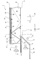
- FIG. 1 is a cross-sectional view schematically showing the configuration of the lighting device 1 according to the first embodiment.
- FIG. 2 is an enlarged cross-sectional view schematically showing the configuration of a main part of the lighting device 1.
- FIG. 3 is an exploded perspective view schematically showing the reflection member 30, the light emitting unit 20, the light source 10, and the optical member 50 of the lighting device 1.
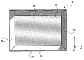
- FIG. 4 is a bottom view schematically showing the configuration of the lighting device 1.
- the lighting device 1 includes a light source 10, a light emitting unit 20, a reflecting member 30, a frame 40, and an optical member 50.
- the light source 10 emits light L10.
- the light source 10 is also referred to as a "first light source”.
- the light source 10 emits light L10 toward, for example, the light emitting unit 20.
- a member such as a light guide path or a mirror for guiding the light L10 may be provided between the light source 10 and the light emitting unit 20.
- the light source 10 is arranged so as to face the side surface 23 of the light emitting unit 20, for example.
- the side surface 23 is also referred to as an "end”.
- the light source 10 is, for example, an array of light emitting elements including a plurality of light emitting elements 11 arranged in a line.
- the light emitting element is, for example, a light emitting diode (LED).
- the plurality of light emitting elements 11 may be arranged in two or more rows.
- the light source 10 is not limited to the light emitting element array, and may be a long lamp light source or the like. Although four light sources 10 are shown in FIG. 3, the number of light sources 10 may be 3 or less or 5 or more.
- the light emitting unit 20 incidents the light L10, which is the first light, and scatters the incident light while guiding it by total reflection and emits it from the light emitting surface.
- the light emitting unit 20 is, for example, a plate-shaped light guide member having a front surface 21, a back surface 22 on the opposite side of the front surface 21, and a side surface 23 connecting the front surface 21 and the back surface 22.
- the front surface 21 is a surface on the observer side.
- the front surface 21 is also referred to as a "light emitting surface” or a "first surface”.
- the back surface 22 is also referred to as a "second surface” or a "back surface”.
- the shape of the light emitting portion 20 is not limited to the plate shape, and may be another shape such as a rod shape.
- the light emitting unit 20 is formed of, for example, a light-transmitting base material 25 and particles 24 dispersed in the base material 25.
- the base material 25 is, for example, a plate-shaped member.
- the particle 24 is a particle that scatters light and is also called a scattering material. The particles 24 scatter light traveling through the substrate 25.
- the particle 24 is, for example, a nanoparticle.
- a “nanoparticle” is a particle having a size on the order of nanometers (nm). Nanoparticles generally refer to particles having a size of 1 nm to several hundred nm (for example, 300 nm). The particle 24 is, for example, a particle having a particle size on the order of nanometers.
- the particles 24 may have a spherical shape or another shape.
- the light emitting unit 20 can include a plurality of types of particles 24.
- the particle size of the particles 24 may be the average particle size.
- Particle 24 is, for example, an inorganic oxide.
- the inorganic oxide is, for example, ZnO, TiO 2 , ZrO 2 , SiO 2 , Al 2 O 3, or the like.
- the base material 25 may contain, for example, particles 24. Further, the particles 24 may be added to the base material 25. The particles 24 are dispersed in, for example, the base material 25.
- the material of the base material 25 is not particularly limited, but is, for example, a transparent material.
- the base material 25 does not necessarily have to be transparent at all wavelengths of incident light.
- the base material 25 may absorb a specific wavelength of the incident light.
- the transmittance (that is, straight-line transmittance) of the base material 25 at a light guide distance of 5 mm is preferably 90% or more, more preferably 95% or more, and preferably 98% or more at the design wavelength. More preferred.
- the design wavelength may be a predetermined wavelength of the incident light wavelengths.
- the design wavelength is not limited to one wavelength, and may be a wavelength having a plurality of wavelengths or widths (that is, a wavelength band).
- the design wavelength may be, for example, one or more of 450 nm, 550 nm and 650 nm when the incident light is white light.
- the design wavelength may be three wavelengths of 450 nm, 550 nm and 650 nm.
- the base material 25 is, for example, a solid.
- the base material 25 may be, for example, a resin plate using a thermoplastic polymer, a thermosetting resin, a photopolymerizable resin, or the like. Further, as the resin plate, an acrylic polymer, an olefin polymer, a vinyl polymer, a cellulose polymer, an amide polymer, a fluorine polymer, a urethane polymer, a silicone polymer, an imide polymer or the like can be used.
- the light emitting portion 20 may be formed, for example, by performing a curing treatment in a state where the particles 24 are dispersed in the material of the base material 25 before curing.
- the light emitting unit 20 may be formed of, for example, a porous material, an organic molecule-dispersed material, an organic-inorganic hybrid material (also referred to as an organic-inorganic nanocomposite material) or a metal particle-dispersed material made by the sol-gel method.
- the light emitting unit 20 may be an organic / inorganic hybrid resin, for example, a hybrid resin of a resin and an inorganic oxide.
- the light emitting unit 20 has an inorganic oxide produced by sol-gel curing based on a base material 25 containing an inorganic oxide material and an organic compound as a substance corresponding to the particles 24.
- fine pores and the like generated by such a manufacturing process are also regarded as particles 24.
- the light emitting portion 20 may have fine irregularities smaller than the wavelength of blue light formed on the surface of the base material 25.
- the light emitting portion 20 has fine concave portions or convex portions formed on the surface of the base material 25 as the particles 24.
- the maximum diameter of the concave portion or the convex portion is preferably on the order of nanometers (for example, a size of 1 nm to several hundred nm).
- the particles 24 and the base material 25 do not have to be clearly distinguished as different members in the light emitting unit 20.
- the base material 25 is not limited to a solid, and may be a liquid, liquid crystal, or gel-like substance.
- the light incident from the side surface 23 of the light emitting unit 20 is totally reflected by the front surface 21 and the back surface 22 to guide the light.
- the light totally reflected is indicated by the reference numeral L11.
- a part of the light incident from the side surface 23 is scattered by the particles 24.
- the light generated by scattering is indicated by reference numeral L12.
- the light emitting unit 20 may have a structure in which a plurality of translucent members are laminated.
- the light incident on the light emitting unit 20 from the side surface 23 is guided and scattered, and is emitted from the front surface 21 or the back surface 22.
- the haze value of the light emitting unit 20 in the thickness direction (that is, the Z-axis direction) of the light emitting unit 20 is preferably in the range of 0.005% to 30%.
- the haze value of the light emitting unit 20 is more preferably in the range of 0.1% to 15%, and even more preferably in the range of 0.5% to 5%.
- the reason for defining the upper limit of the haze value in the Z-axis direction of the light emitting unit 20 is that when the haze value is sufficiently high, the bright spot, that is, the height of the reflecting member 30 generated due to the reflection of light by the optical member 50. This is because the brightness region 31 is difficult to be recognized by the observer. That is, when the haze value is sufficiently high, the degree of cloudiness of the light emitting unit 20 is high, so even if the high-luminance region 31 is generated on the back surface 22 side of the light emitting unit 20, the front surface 21 side of the light emitting unit 20 This is because the observer in is not aware of the uneven brightness on the front surface 21. In other words, when the haze value is sufficiently high, the reflectance of the optical member 50 has almost no effect on the state of the front surface 21 of the light emitting unit 20 of the lighting device 1 observed by the observer.
- the reflecting member 30 is provided so as to face the back surface, which is the surface opposite to the light emitting surface of the light emitting unit 20, and reflects the light emitted from the back surface of the light emitting unit 20.
- the reflective member 30 is also referred to as a back reflective portion.
- a space, that is, an air layer exists between the reflective member 30 and the back surface 22 of the light emitting unit 20. This is so that total reflection occurs on the back surface 22 of the light emitting unit 20.
- the reflecting member 30 reflects the light emitted from the back surface 22 of the light emitting unit 20 without satisfying the total reflection condition and directs it toward the back surface 22, that is, returns it from the back surface 22 to the light emitting unit 20.
- the reflective member 30 has a property of reflecting light.
- the reflective member 30 is, for example, a member having a white reflective surface.
- the reflective member 30 is, for example, a film, a sheet metal which is a plate-shaped metal, a plastic plate, or the like.
- the reflective surface of the reflective member 30 may be a diffuse reflective surface.
- the diffuse reflection surface may be formed by, for example, white coating.
- the frame 40 includes a portion located at least in front of the light emitting surface of the light emitting unit 20 (in this example, the front surface 21 in the drawing) (that is, in the + Z axis direction).
- the frame 40 has, for example, the portion facing the first region on the front surface 21 and the opening 42 through which the illumination light L14, which is the light emitted from the second region adjacent to the first region on the front surface 21, is passed.
- the first region is an outer peripheral region
- the second region is a region near the center.
- the first region and the second region on the front surface 21 of the light emitting unit 20 are names for convenience, and there is no physical boundary between the first region and the second region, and the above example. Not limited to.
- the frame 40 does not necessarily have to have an opening (in this case, the entire periphery thereof represents an area surrounded by some member), and for example, two or more parts are arranged with a predetermined gap in between. And so on.
- the gap may be regarded as an opening through which the illumination light L14 passes.
- the region where the frame 40 is located in front may be regarded as the first region, and the region where the frame 40 is not located in front may be regarded as the second region.
- the frame 40 is made of metal, plastic, or the like.
- the frame 40 may be a housing of the lighting device 1 or a part thereof.
- the frame 40 may be a design member having both design and functionality.
- the opening 42 is a space in which nothing exists, or a translucent member through which light can pass.
- the first region is a region including the outer peripheral end of the front surface 21 which is the side of the side surface 23 of the light emitting unit 20.
- the optical member 50 is provided between the light emitting unit 20 and the frame 40, and the frame 40 is positioned in front of a part of the light emitted from the front surface 21 of the light emitting unit 20 (particularly, the light emitted from the front surface 21). Reflects the light emitted from the area where the light is emitted. More specifically, the optical member 50 is arranged between the light emitting unit 20 and the frame 40, particularly on the optical path of the light emitted from the front surface 21 of the light emitting unit 20 and reaching the frame 40. The optical member 50 may be arranged in a region where the front surface 21 of the light emitting unit 20 and the frame 40 overlap when viewed from above.
- the optical member 50 may have, for example, an upper surface 51 which is a surface facing the first region.
- the upper surface 51 is also referred to as a "third surface".
- the optical member 50 may or may not be in contact with the front surface 21 of the light emitting unit 20 and the frame 40.
- the optical member 50 may include an air layer or the like between the light emitting unit 20 and / or the frame 40.
- a part of the light emitted from the first region of the light emitting unit 20 is reflected by, for example, the upper surface 51 of the optical member 50, and travels from the first region into the light emitting unit 20.
- the optical member 50 is not necessarily limited to the one that reflects light on the upper surface 51, and may be at least one that reflects incident light. Further, the optical member 50 does not have to reflect all the light incident on the optical member 50. In other words, the reflectance of the optical member 50 may be lower than 100%.
- the optical member 50 is made of, for example, paint, film, paper, resin, or the like. Further, the optical member 50 may be formed integrally with the frame 40. That is, the end portion of the frame 40 on the front surface 21 side of the light emitting portion 20 may be formed by the optical member 50. As an example, the upper surface of the frame 40 (the surface forming the end portion on the front surface 21 side of the light emitting portion 20) may be formed by the optical member 50.
- the reflectance of the optical member 50 is in the range of 20% to 60%. It is more desirable that the reflectance of the optical member 50 is in the range of 45% to 55%.
- the range of the reflectance may be read as the reflectance of the light incident from the upper surface 51 side of the optical member 50. However, the range of the reflectance can be applied to light other than the light incident from the upper surface 51 side.
- the reason for defining the upper limit of the reflectance of the optical member 50 is that when the reflectance is too high, the brightness of the high-luminance region 31 of the reflective member 30 generated due to the reflection of light by the optical member 50 increases. This is because it is easily recognized as a bright spot by the observer. That is, when the reflectance of the optical member 50 is too high, the observer on the front surface 21 side of the light emitting unit 20 strongly recognizes the high brightness region 31 appearing on the back surface 22 side of the light emitting unit 20. This is because it is difficult for an observer who recognizes such non-uniformity of brightness to perceive natural light emission by the lighting device 1. As shown in FIG.
- the observer recognizes a bright spot in the vicinity region A1 of the frame 40 on the front surface 21 of the light emitting unit 20.
- the presence of the reflective member 30 provided for improving the light utilization efficiency may be recognized by the observer, and other regions (particularly the peripheral region) may feel darker, giving an unnatural feeling. is there.
- the reason for defining the lower limit of the reflectance of the optical member 50 is that when the reflectance is too low, the brightness in the low-luminance region, which is a dark point of the reflecting member 30, generated due to the reflection of light by the optical member 50. This is because it is lowered and easily recognized as a dark spot by the observer. That is, when the reflectance of the optical member 50 is too low, the observer on the front surface 21 side of the light emitting unit 20 strongly recognizes the low-luminance region appearing on the back surface 22 side of the light emitting unit 20. An observer who recognizes such non-uniformity of brightness is unlikely to perceive natural light emission by the lighting device 1 as described above.
- the observer recognizes a dark spot in the vicinity region A1 of the frame 40 on the front surface 21 of the light emitting unit 20.
- the presence of the reflective member 30 provided for improving the light utilization efficiency may be recognized by the observer, and other regions (particularly the peripheral region) may feel brighter, giving an unnatural feeling. There is.
- the brightness of each position of the front surface 21 of the light emitting unit 20 recognized by the observer located on the front surface 21 side of the lighting device 1 is determined according to the amount of light emitted from each position.
- the light emitted from the front surface 21 of the light emitting unit 20 includes, for example, the following lights (L1) to (L4).
- L3 Light incident on the light emitting portion 20 from the side surface 23 and incident on the front surface 21 at an angle that does not satisfy the total reflection condition.
- (L4) Return light of outside light.
- the light emitted from the lighting device 1 is reflected by the wall or floor of the room, enters the light emitting unit 20 from the front surface 21, is reflected by the reflecting member 30, and heads toward the front surface 21. It is light.
- the light emitting unit 20 Since various lights such as (L1) to (L4) are emitted from the light emitting unit 20, if a member having a high reflectance (for example, a metal frame) is present in front of the front surface 21, the light is emitted from the front surface 21. It is possible that the light is reflected by the frame 40 and reaches the reflecting member 30 to generate a high-brightness region 31. Further, if a member having a low reflectance is present in front of the front surface 21, the shadow of the member having a low reflectance may reach the reflecting member 30 to generate a low brightness region. In order to prevent the occurrence of these bright spots and dark spots, it is desirable to set the reflectance of the optical member 50 within the above-mentioned reflectance range.
- the reflectance of the optical member 50 is, for example, the reflectance for light incident from the upper surface side of the optical member 50.
- FIG. 5 is a functional block diagram schematically showing the configuration of the control system of the lighting device 1.
- the lighting device 1 is, for example, a light source driving unit 12 which is a driving circuit for turning on, dimming, or turning off the light source 10, and a lighting control device which is a control circuit for controlling the light source driving unit 12. It is equipped with 13.
- the lighting control device 13 may have a memory for storing a program and a processor for executing the program.
- the lighting control device 13 can control the lighting, dimming, and extinguishing of the light source 10 so as to have a certain relationship with, for example, time, weather, and season. Dimming may include adjusting the intensity of light, adjusting the color of light.
- the unnatural brightness distribution of the light emitting unit 20 caused by the frame 40 provided in front of the light emitting unit can be suppressed, and more natural light emission can be realized. That is, if the lighting device 1 is used, it is possible to realize light emission that does not give the observer an unnatural feeling, that is, light emission that does not make the observer feel unnatural. For example, the observer can feel that the lighting device 1 simulates a window in which natural light is incident. That is, the observer can feel that the pseudo sky is reproduced by the lighting device 1.
- FIG. 6 is a cross-sectional view schematically showing the configuration of the lighting device 1a according to the modified example of the first embodiment.
- FIG. 7 is an enlarged cross-sectional view schematically showing the configuration of a main part of the lighting device 1a. 6 and 7 show a case where the lighting device 1a is attached to the ceiling 90. As shown in FIGS. 6 and 7, the frame may be located away from the end of the light emitting unit 20. That is, the first region of the front surface 21 of the light emitting unit 20 may be a region that does not include the outer peripheral end of the front surface 21. According to the lighting device 1a, the configuration can be simplified as compared with the lighting device 1.
- FIG. 8 is a cross-sectional view schematically showing the configuration of a main part of the lighting device 2 according to the second embodiment.
- the same or corresponding components as those shown in FIG. 2 are designated by the same reference numerals as those shown in FIG.
- the lighting device 2 according to the second embodiment is different from the lighting device 1 according to the first embodiment in that it has the shape of the frame 70 and the light source 60.
- Embodiment 2 is the same as Embodiment 1.
- the light source 60 emits light.
- the light source 60 is also referred to as a "second light source”.
- the light source 60 is arranged outside the frame 70.
- the light source 60 has the same configuration as the light source 10. However, the light source 60 may have a configuration different from that of the light source 10. Further, instead of the light source 60, an optical branching member or a light guide member that directs a part of the light emitted by the light source 10 toward the frame 70 may be provided.
- the frame 70 has a wall-shaped portion 73 on the front surface 21 of the light emitting unit 20.
- the frame 70 is, for example, a translucent member.
- the frame 70 may include a light diffusing material that diffuses light.
- the frame 70 is formed so as to surround the space in front of the front surface 21.
- the frame 70 may be inclined with respect to the normal line of the front surface 21 so that the space in front of the front surface 21 expands as the distance from the front surface 21 increases.
- the frame 70 is composed of four surfaces, the number of portions 73 constituting the frame 70 may be other than the four surfaces. Further, the frame 70 may include a curved surface.
- the light from the light source 60 also referred to as “second light” is incident on the frame 70, transmitted and diffused, and then emitted from the surface of the frame 70.
- the optical member 50 has an upper surface 51 which is a surface facing the front surface side of the light emitting unit 20, and a lower surface 52 which is a surface facing the frame 70 side.
- the lower surface 52 is also referred to as a "fourth surface".
- the frame 70 is made of, for example, resin, glass, or film.
- the reflectance of the lower surface 52 is preferably 70% or more. It is more desirable that the reflectance of the lower surface 52 is 90% or more.
- the reflectance of the upper surface 51 and the reflectance of the lower surface 52 of the optical member 50 are the reflectance to the light incident on the upper surface 51 side of the optical member 50 (for example, the light traveling in the + Z direction in the drawing) and the lower surface 52 side, respectively. It may be read as the reflectance for the light incident from (for example, the light traveling in the ⁇ Z direction in the figure).
- the light source 60 is arranged outside the frame 70 and irradiates light from the outside of the frame 70.
- the light emitted by the light source 60 passes through the frame 70, or diffuses and passes through, and is emitted as light L15 in the space in front of the front surface 21.
- the frame 70 can simulate a window frame.
- FIG. 9 is a bottom view showing an example of a bright region 73a and a dark region 73b of the frame 70 of the lighting device 2.
- FIG. 10 is a bottom view showing another example of the bright region 73a and the dark region 73b of the frame 70.
- the bright region 73a is a region having a high light transmittance
- the dark region 73b is a region having a lower light transmittance than the bright region 73a.
- the observer can feel the bright region 73a and the dark region 73b as if they were sun and shade formed on the window frame. That is, the observer can feel as if the actual sunlight, that is, natural light is shining from the light emitting unit 20.
- FIG. 11 is a functional block diagram schematically showing the configuration of the control system of the lighting device 2.
- the lighting device 2 includes a light source driving unit 62 which is a driving circuit for turning on, dimming, or turning off the light source 60, and a lighting control device 13 which is a control circuit for controlling the light source driving unit 62. Is equipped with.
- the lighting control device 13 may have a memory for storing a program and a processor for executing the program.
- the lighting control device 13 can control the lighting, dimming, and extinguishing of the light source 10 and the light source 60 so as to have a certain relationship with, for example, time, weather, season, and so on. Dimming may include adjusting the intensity of light, adjusting the color of light.
- the unnatural brightness distribution of the light emitting unit 20 caused by the member provided in front of the light emitting unit 20 can be suppressed, and more natural light emission can be realized.
- the observer can feel that the lighting device 2 simulates a window in which natural light is incident. That is, the observer can feel that the pseudo sky is reproduced by the lighting device 2.
Landscapes
- Physics & Mathematics (AREA)
- General Physics & Mathematics (AREA)
- Optics & Photonics (AREA)
- Engineering & Computer Science (AREA)
- General Engineering & Computer Science (AREA)
- Planar Illumination Modules (AREA)
- Non-Portable Lighting Devices Or Systems Thereof (AREA)
Abstract
Dispositif d'éclairage (1) pourvu de ce qui suit : une source de lumière (10) pour émettre une première lumière ; une partie d'émission de lumière (20) pour recevoir la première lumière, guider la première lumière reçue par réflexion totale, et la diffuser et l'émettre à partir d'une surface d'émission de lumière ; une partie de réflexion arrière (30) qui est disposée de façon à faire face à une surface arrière de la partie d'émission de lumière (20) qui est sur le côté opposé à la surface d'émission de lumière, et qui réfléchit la lumière émise à partir de la surface arrière de la partie d'émission de lumière (20) ; un cadre (40) comprenant une partie qui est positionnée au moins devant la surface d'émission de lumière de la partie d'émission de lumière (20) ; et un élément optique (50) qui est disposé entre la surface d'émission de lumière de la partie d'émission de lumière (20) et la partie susmentionnée du cadre (40) et réfléchit une partie de la lumière émise à partir de la surface d'émission de lumière de la partie d'émission de lumière (20).
Priority Applications (5)
| Application Number | Priority Date | Filing Date | Title |
|---|---|---|---|
| PCT/JP2019/033453 WO2021038709A1 (fr) | 2019-08-27 | 2019-08-27 | Dispositif d'éclairage |
| EP19943422.6A EP4023932A4 (fr) | 2019-08-27 | 2019-08-27 | Dispositif d'éclairage |
| CN201980099486.XA CN114270094A (zh) | 2019-08-27 | 2019-08-27 | 照明装置 |
| US17/636,380 US11828973B2 (en) | 2019-08-27 | 2019-08-27 | Illumination device |
| JP2021541831A JP7297071B2 (ja) | 2019-08-27 | 2019-08-27 | 照明装置 |
Applications Claiming Priority (1)
| Application Number | Priority Date | Filing Date | Title |
|---|---|---|---|
| PCT/JP2019/033453 WO2021038709A1 (fr) | 2019-08-27 | 2019-08-27 | Dispositif d'éclairage |
Publications (1)
| Publication Number | Publication Date |
|---|---|
| WO2021038709A1 true WO2021038709A1 (fr) | 2021-03-04 |
Family
ID=74684659
Family Applications (1)
| Application Number | Title | Priority Date | Filing Date |
|---|---|---|---|
| PCT/JP2019/033453 WO2021038709A1 (fr) | 2019-08-27 | 2019-08-27 | Dispositif d'éclairage |
Country Status (5)
| Country | Link |
|---|---|
| US (1) | US11828973B2 (fr) |
| EP (1) | EP4023932A4 (fr) |
| JP (1) | JP7297071B2 (fr) |
| CN (1) | CN114270094A (fr) |
| WO (1) | WO2021038709A1 (fr) |
Citations (6)
| Publication number | Priority date | Publication date | Assignee | Title |
|---|---|---|---|---|
| JPH08190023A (ja) * | 1994-11-10 | 1996-07-23 | Nissha Printing Co Ltd | 面発光装置 |
| JPH10161119A (ja) * | 1996-11-29 | 1998-06-19 | Optrex Corp | バックライト構造 |
| WO2007029679A1 (fr) * | 2005-09-06 | 2007-03-15 | Kuraray Co., Ltd. | Guide lumineux en résine méthacrylique diffusive et dispositif de source lumineuse superficielle l’utilisant |
| JP2011099899A (ja) * | 2009-11-04 | 2011-05-19 | Maruzen Chemicals Co Ltd | 光散乱部材およびその製造方法 |
| JP2012069245A (ja) * | 2009-08-28 | 2012-04-05 | Fujifilm Corp | 面状照明装置 |
| JP2018060624A (ja) | 2016-10-03 | 2018-04-12 | パナソニックIpマネジメント株式会社 | 照明装置 |
Family Cites Families (21)
| Publication number | Priority date | Publication date | Assignee | Title |
|---|---|---|---|---|
| US5530571A (en) * | 1995-01-06 | 1996-06-25 | Chen; Hung-Wen | Two-purpose LCD device with scrollable reflecting screen and scrollable diffusing screen |
| JP2003278376A (ja) | 2002-03-22 | 2003-10-02 | Eisuke Fujimoto | 疑似明かり窓 |
| US20060274551A1 (en) * | 2005-05-26 | 2006-12-07 | Enplas Corporation | Surface light source device and display |
| JP4584312B2 (ja) * | 2005-08-26 | 2010-11-17 | シーシーエス株式会社 | 光照射装置及び光学部材 |
| BRPI0720904A2 (pt) | 2007-01-03 | 2014-04-15 | Koninkl Philips Electronics Nv | Dispositivo de exibição |
| CN102395915B (zh) * | 2009-04-22 | 2014-04-16 | 株式会社藤仓 | 显示装置以及采光窗 |
| WO2011141779A1 (fr) * | 2010-05-12 | 2011-11-17 | Oree, Advanced Illumination Solutions Inc. | Appareil d'éclairage à efficacité de conversion élevée et procédés de fabrication correspondants |
| JP2012088661A (ja) | 2010-10-22 | 2012-05-10 | Mitsubishi Plastics Inc | 液晶表示装置におけるフレーム部材 |
| US9322976B2 (en) * | 2012-02-17 | 2016-04-26 | Sharp Kabushiki Kaisha | Lighting device, display device and television device |
| JP5721668B2 (ja) * | 2012-06-29 | 2015-05-20 | シャープ株式会社 | 発光装置、照明装置および表示装置用バックライト |
| JP2014049261A (ja) * | 2012-08-30 | 2014-03-17 | Sharp Corp | 照明装置 |
| JP2015076357A (ja) | 2013-10-11 | 2015-04-20 | 住友化学株式会社 | 面発光装置 |
| TWI544271B (zh) * | 2015-04-10 | 2016-08-01 | 元太科技工業股份有限公司 | 反射式顯示裝置 |
| JP2017183118A (ja) | 2016-03-30 | 2017-10-05 | 大日本印刷株式会社 | 導光板および照明装置 |
| JP6767717B2 (ja) | 2016-07-12 | 2020-10-14 | パナソニックIpマネジメント株式会社 | 照明装置 |
| US10502374B2 (en) | 2017-01-30 | 2019-12-10 | Ideal Industries Lighting Llc | Light fixtures and methods |
| JP6964242B2 (ja) | 2017-03-29 | 2021-11-10 | パナソニックIpマネジメント株式会社 | 照明装置および照明システム |
| US10718489B2 (en) * | 2017-03-24 | 2020-07-21 | Panasonic Intellectual Property Management Co., Ltd. | Illumination system and illumination control method |
| GB2565398B (en) * | 2018-05-11 | 2019-07-31 | Thorpe F W Plc | Ceiling luminaire |
| CN112119259B (zh) * | 2018-05-18 | 2023-05-30 | 三菱电机株式会社 | 照明单元和照明器具 |
| EP3978796B1 (fr) | 2019-05-27 | 2024-02-21 | Mitsubishi Electric Corporation | Dispositif d'éclairage |
-
2019
- 2019-08-27 WO PCT/JP2019/033453 patent/WO2021038709A1/fr unknown
- 2019-08-27 EP EP19943422.6A patent/EP4023932A4/fr active Pending
- 2019-08-27 JP JP2021541831A patent/JP7297071B2/ja active Active
- 2019-08-27 US US17/636,380 patent/US11828973B2/en active Active
- 2019-08-27 CN CN201980099486.XA patent/CN114270094A/zh active Pending
Patent Citations (6)
| Publication number | Priority date | Publication date | Assignee | Title |
|---|---|---|---|---|
| JPH08190023A (ja) * | 1994-11-10 | 1996-07-23 | Nissha Printing Co Ltd | 面発光装置 |
| JPH10161119A (ja) * | 1996-11-29 | 1998-06-19 | Optrex Corp | バックライト構造 |
| WO2007029679A1 (fr) * | 2005-09-06 | 2007-03-15 | Kuraray Co., Ltd. | Guide lumineux en résine méthacrylique diffusive et dispositif de source lumineuse superficielle l’utilisant |
| JP2012069245A (ja) * | 2009-08-28 | 2012-04-05 | Fujifilm Corp | 面状照明装置 |
| JP2011099899A (ja) * | 2009-11-04 | 2011-05-19 | Maruzen Chemicals Co Ltd | 光散乱部材およびその製造方法 |
| JP2018060624A (ja) | 2016-10-03 | 2018-04-12 | パナソニックIpマネジメント株式会社 | 照明装置 |
Non-Patent Citations (1)
| Title |
|---|
| See also references of EP4023932A4 |
Also Published As
| Publication number | Publication date |
|---|---|
| EP4023932A1 (fr) | 2022-07-06 |
| US20220268988A1 (en) | 2022-08-25 |
| CN114270094A (zh) | 2022-04-01 |
| US11828973B2 (en) | 2023-11-28 |
| EP4023932A4 (fr) | 2022-07-06 |
| JP7297071B2 (ja) | 2023-06-23 |
| JPWO2021038709A1 (fr) | 2021-03-04 |
Similar Documents
| Publication | Publication Date | Title |
|---|---|---|
| JP6778914B2 (ja) | 照明装置 | |
| US11879634B2 (en) | Illumination device | |
| JP6767717B2 (ja) | 照明装置 | |
| US20130176741A1 (en) | Light flux controlling member and illumination device | |
| TW200925507A (en) | Light emitting device and lighting device having the same | |
| CN108692224B (zh) | 照明装置及照明系统 | |
| JP2007227410A (ja) | 発光装置、面光源装置、表示装置及び光束制御部材 | |
| WO2011024641A1 (fr) | Élément optique et dispositif d'émission de lumière | |
| JP2007141546A (ja) | 光混合板、及び該光混合板を利用した直下式バックライト | |
| WO2020240933A1 (fr) | Corps de diffusion et dispositif d'éclairage | |
| CN210179385U (zh) | 一种遮阳板化妆镜灯发光模块 | |
| WO2021038709A1 (fr) | Dispositif d'éclairage | |
| US11561334B2 (en) | Diffusive body and illumination device | |
| WO2011083779A1 (fr) | Élément optique et dispositif émetteur de lumière | |
| JP7386835B2 (ja) | 照明装置 | |
| KR102376090B1 (ko) | 조명장치 | |
| WO2018235803A1 (fr) | Élément d'éclairage naturel et dispositif d'éclairage naturel | |
| US20230151958A1 (en) | Lighting device, air conditioner, and control system | |
| CN218914629U (zh) | 一种侧发光平板灯和一种照明装置 | |
| JP2021166188A (ja) | 照明装置 | |
| JP2022116850A (ja) | 面光源装置、表示装置および光束制御部材 | |
| JPH0963332A (ja) | 面状光源装置 | |
| KR20160033927A (ko) | 반사형 프로젝터용 스크린 |
Legal Events
| Date | Code | Title | Description |
|---|---|---|---|
| 121 | Ep: the epo has been informed by wipo that ep was designated in this application |
Ref document number: 19943422 Country of ref document: EP Kind code of ref document: A1 |
|
| ENP | Entry into the national phase |
Ref document number: 2021541831 Country of ref document: JP Kind code of ref document: A |
|
| NENP | Non-entry into the national phase |
Ref country code: DE |
|
| ENP | Entry into the national phase |
Ref document number: 2019943422 Country of ref document: EP Effective date: 20220328 |