WO2021038617A1 - 電力変換制御装置 - Google Patents
電力変換制御装置 Download PDFInfo
- Publication number
- WO2021038617A1 WO2021038617A1 PCT/JP2019/032961 JP2019032961W WO2021038617A1 WO 2021038617 A1 WO2021038617 A1 WO 2021038617A1 JP 2019032961 W JP2019032961 W JP 2019032961W WO 2021038617 A1 WO2021038617 A1 WO 2021038617A1
- Authority
- WO
- WIPO (PCT)
- Prior art keywords
- voltage
- power
- low
- insulated
- circuit
- Prior art date
Links
Images


Classifications
-
- H—ELECTRICITY
- H02—GENERATION; CONVERSION OR DISTRIBUTION OF ELECTRIC POWER
- H02M—APPARATUS FOR CONVERSION BETWEEN AC AND AC, BETWEEN AC AND DC, OR BETWEEN DC AND DC, AND FOR USE WITH MAINS OR SIMILAR POWER SUPPLY SYSTEMS; CONVERSION OF DC OR AC INPUT POWER INTO SURGE OUTPUT POWER; CONTROL OR REGULATION THEREOF
- H02M7/00—Conversion of ac power input into dc power output; Conversion of dc power input into ac power output
- H02M7/42—Conversion of dc power input into ac power output without possibility of reversal
- H02M7/44—Conversion of dc power input into ac power output without possibility of reversal by static converters
- H02M7/48—Conversion of dc power input into ac power output without possibility of reversal by static converters using discharge tubes with control electrode or semiconductor devices with control electrode
- H02M7/53—Conversion of dc power input into ac power output without possibility of reversal by static converters using discharge tubes with control electrode or semiconductor devices with control electrode using devices of a triode or transistor type requiring continuous application of a control signal
- H02M7/537—Conversion of dc power input into ac power output without possibility of reversal by static converters using discharge tubes with control electrode or semiconductor devices with control electrode using devices of a triode or transistor type requiring continuous application of a control signal using semiconductor devices only, e.g. single switched pulse inverters
-
- H—ELECTRICITY
- H02—GENERATION; CONVERSION OR DISTRIBUTION OF ELECTRIC POWER
- H02M—APPARATUS FOR CONVERSION BETWEEN AC AND AC, BETWEEN AC AND DC, OR BETWEEN DC AND DC, AND FOR USE WITH MAINS OR SIMILAR POWER SUPPLY SYSTEMS; CONVERSION OF DC OR AC INPUT POWER INTO SURGE OUTPUT POWER; CONTROL OR REGULATION THEREOF
- H02M1/00—Details of apparatus for conversion
- H02M1/08—Circuits specially adapted for the generation of control voltages for semiconductor devices incorporated in static converters
-
- B—PERFORMING OPERATIONS; TRANSPORTING
- B60—VEHICLES IN GENERAL
- B60L—PROPULSION OF ELECTRICALLY-PROPELLED VEHICLES; SUPPLYING ELECTRIC POWER FOR AUXILIARY EQUIPMENT OF ELECTRICALLY-PROPELLED VEHICLES; ELECTRODYNAMIC BRAKE SYSTEMS FOR VEHICLES IN GENERAL; MAGNETIC SUSPENSION OR LEVITATION FOR VEHICLES; MONITORING OPERATING VARIABLES OF ELECTRICALLY-PROPELLED VEHICLES; ELECTRIC SAFETY DEVICES FOR ELECTRICALLY-PROPELLED VEHICLES
- B60L9/00—Electric propulsion with power supply external to the vehicle
- B60L9/16—Electric propulsion with power supply external to the vehicle using ac induction motors
- B60L9/18—Electric propulsion with power supply external to the vehicle using ac induction motors fed from dc supply lines
-
- H—ELECTRICITY
- H02—GENERATION; CONVERSION OR DISTRIBUTION OF ELECTRIC POWER
- H02M—APPARATUS FOR CONVERSION BETWEEN AC AND AC, BETWEEN AC AND DC, OR BETWEEN DC AND DC, AND FOR USE WITH MAINS OR SIMILAR POWER SUPPLY SYSTEMS; CONVERSION OF DC OR AC INPUT POWER INTO SURGE OUTPUT POWER; CONTROL OR REGULATION THEREOF
- H02M1/00—Details of apparatus for conversion
- H02M1/0003—Details of control, feedback or regulation circuits
- H02M1/0006—Arrangements for supplying an adequate voltage to the control circuit of converters
-
- H—ELECTRICITY
- H02—GENERATION; CONVERSION OR DISTRIBUTION OF ELECTRIC POWER
- H02M—APPARATUS FOR CONVERSION BETWEEN AC AND AC, BETWEEN AC AND DC, OR BETWEEN DC AND DC, AND FOR USE WITH MAINS OR SIMILAR POWER SUPPLY SYSTEMS; CONVERSION OF DC OR AC INPUT POWER INTO SURGE OUTPUT POWER; CONTROL OR REGULATION THEREOF
- H02M1/00—Details of apparatus for conversion
- H02M1/08—Circuits specially adapted for the generation of control voltages for semiconductor devices incorporated in static converters
- H02M1/088—Circuits specially adapted for the generation of control voltages for semiconductor devices incorporated in static converters for the simultaneous control of series or parallel connected semiconductor devices
-
- H—ELECTRICITY
- H02—GENERATION; CONVERSION OR DISTRIBUTION OF ELECTRIC POWER
- H02M—APPARATUS FOR CONVERSION BETWEEN AC AND AC, BETWEEN AC AND DC, OR BETWEEN DC AND DC, AND FOR USE WITH MAINS OR SIMILAR POWER SUPPLY SYSTEMS; CONVERSION OF DC OR AC INPUT POWER INTO SURGE OUTPUT POWER; CONTROL OR REGULATION THEREOF
- H02M3/00—Conversion of dc power input into dc power output
- H02M3/22—Conversion of dc power input into dc power output with intermediate conversion into ac
- H02M3/24—Conversion of dc power input into dc power output with intermediate conversion into ac by static converters
- H02M3/28—Conversion of dc power input into dc power output with intermediate conversion into ac by static converters using discharge tubes with control electrode or semiconductor devices with control electrode to produce the intermediate ac
- H02M3/325—Conversion of dc power input into dc power output with intermediate conversion into ac by static converters using discharge tubes with control electrode or semiconductor devices with control electrode to produce the intermediate ac using devices of a triode or a transistor type requiring continuous application of a control signal
- H02M3/335—Conversion of dc power input into dc power output with intermediate conversion into ac by static converters using discharge tubes with control electrode or semiconductor devices with control electrode to produce the intermediate ac using devices of a triode or a transistor type requiring continuous application of a control signal using semiconductor devices only
- H02M3/33507—Conversion of dc power input into dc power output with intermediate conversion into ac by static converters using discharge tubes with control electrode or semiconductor devices with control electrode to produce the intermediate ac using devices of a triode or a transistor type requiring continuous application of a control signal using semiconductor devices only with automatic control of the output voltage or current, e.g. flyback converters
- H02M3/33523—Conversion of dc power input into dc power output with intermediate conversion into ac by static converters using discharge tubes with control electrode or semiconductor devices with control electrode to produce the intermediate ac using devices of a triode or a transistor type requiring continuous application of a control signal using semiconductor devices only with automatic control of the output voltage or current, e.g. flyback converters with galvanic isolation between input and output of both the power stage and the feedback loop
-
- H—ELECTRICITY
- H02—GENERATION; CONVERSION OR DISTRIBUTION OF ELECTRIC POWER
- H02P—CONTROL OR REGULATION OF ELECTRIC MOTORS, ELECTRIC GENERATORS OR DYNAMO-ELECTRIC CONVERTERS; CONTROLLING TRANSFORMERS, REACTORS OR CHOKE COILS
- H02P27/00—Arrangements or methods for the control of AC motors characterised by the kind of supply voltage
- H02P27/04—Arrangements or methods for the control of AC motors characterised by the kind of supply voltage using variable-frequency supply voltage, e.g. inverter or converter supply voltage
- H02P27/06—Arrangements or methods for the control of AC motors characterised by the kind of supply voltage using variable-frequency supply voltage, e.g. inverter or converter supply voltage using dc to ac converters or inverters
-
- H—ELECTRICITY
- H02—GENERATION; CONVERSION OR DISTRIBUTION OF ELECTRIC POWER
- H02M—APPARATUS FOR CONVERSION BETWEEN AC AND AC, BETWEEN AC AND DC, OR BETWEEN DC AND DC, AND FOR USE WITH MAINS OR SIMILAR POWER SUPPLY SYSTEMS; CONVERSION OF DC OR AC INPUT POWER INTO SURGE OUTPUT POWER; CONTROL OR REGULATION THEREOF
- H02M7/00—Conversion of ac power input into dc power output; Conversion of dc power input into ac power output
- H02M7/42—Conversion of dc power input into ac power output without possibility of reversal
- H02M7/44—Conversion of dc power input into ac power output without possibility of reversal by static converters
- H02M7/48—Conversion of dc power input into ac power output without possibility of reversal by static converters using discharge tubes with control electrode or semiconductor devices with control electrode
- H02M7/53—Conversion of dc power input into ac power output without possibility of reversal by static converters using discharge tubes with control electrode or semiconductor devices with control electrode using devices of a triode or transistor type requiring continuous application of a control signal
- H02M7/537—Conversion of dc power input into ac power output without possibility of reversal by static converters using discharge tubes with control electrode or semiconductor devices with control electrode using devices of a triode or transistor type requiring continuous application of a control signal using semiconductor devices only, e.g. single switched pulse inverters
- H02M7/5387—Conversion of dc power input into ac power output without possibility of reversal by static converters using discharge tubes with control electrode or semiconductor devices with control electrode using devices of a triode or transistor type requiring continuous application of a control signal using semiconductor devices only, e.g. single switched pulse inverters in a bridge configuration
-
- Y—GENERAL TAGGING OF NEW TECHNOLOGICAL DEVELOPMENTS; GENERAL TAGGING OF CROSS-SECTIONAL TECHNOLOGIES SPANNING OVER SEVERAL SECTIONS OF THE IPC; TECHNICAL SUBJECTS COVERED BY FORMER USPC CROSS-REFERENCE ART COLLECTIONS [XRACs] AND DIGESTS
- Y02—TECHNOLOGIES OR APPLICATIONS FOR MITIGATION OR ADAPTATION AGAINST CLIMATE CHANGE
- Y02T—CLIMATE CHANGE MITIGATION TECHNOLOGIES RELATED TO TRANSPORTATION
- Y02T90/00—Enabling technologies or technologies with a potential or indirect contribution to GHG emissions mitigation
- Y02T90/10—Technologies relating to charging of electric vehicles
- Y02T90/16—Information or communication technologies improving the operation of electric vehicles
Definitions
- the present application relates to a power conversion control device used in an electric vehicle.
- electric vehicles such as electric vehicles and hybrid vehicles are equipped with an AC rotating electric machine as a driving source of the vehicle. Power is supplied to this AC rotary electric machine by a power conversion control device.
- a power conversion control device a control circuit for controlling a vehicle powered by a low-voltage battery and a drive circuit for driving a vehicle powered by a high-voltage battery are electrically isolated.
- an isolated communication circuit for electrically communicating the low voltage side and the high voltage side.
- an insulated power supply is required on the low-voltage side and the high-voltage side of the insulated communication circuit, a predetermined insulation distance is provided between the low-voltage power supply and the high-voltage power supply, which are the power supply sources of the isolated power supply. This is a factor in increasing the size of the power conversion control device itself.
- Patent Document 1 proposes to reliably protect the system in the event of an abnormality while making the power supply, the power supply generation circuit, and the like redundant to the minimum necessary. ..
- Patent Document 1 shows that an insulated power source is diverted.
- the power supply path of the insulated power supply is branched into two, and the power supply is diverted to the discharge drive circuit and the lower arm side drive circuit, which are the supply destinations, to realize the redundancy of the insulated power supply.
- Patent Document 1 does not mention the individual operation of the insulated power supply, and it cannot be said that consideration for power saving, miniaturization, and cost reduction is sufficient, and there is room for improvement.
- This application has been made to solve the above-mentioned problems, and provides a compact, inexpensive, and low current consumption power conversion control device.
- the power conversion control device disclosed in the present application is generated by step-down from a high voltage side connected to a high voltage battery used as a drive power source for an electric vehicle and a low voltage battery or a high voltage battery used as a control power source for the electric vehicle.
- the low voltage side connected to the low voltage power supply is electrically insulated, and the processing unit on the low voltage side converts the DC power on the high voltage side to AC power, or the AC power generated from the three-phase motor to DC power.
- a power conversion control device that controls a gate-isolated transistor for driving a three-phase motor to be converted.
- a constant-voltage circuit in which power is supplied from a low-voltage battery or a low-voltage power supply, and a constant voltage It is equipped with a processing unit that supplies constant voltage power from the circuit, and has a plurality of gate-isolated transistors that convert DC power obtained from a high-voltage battery into AC power on the high-voltage side.
- a processing unit that supplies constant voltage power from the circuit, and has a plurality of gate-isolated transistors that convert DC power obtained from a high-voltage battery into AC power on the high-voltage side.
- Powered from a low-voltage battery or low-voltage power source including a phase motor drive circuit and a voltage measuring circuit that measures the voltage of the high-voltage battery, and located between the low-voltage side and the high-voltage side.
- a power conversion control device equipped with an isolated communication circuit for transmission, a pair of insulated power supplies are connected to the gate drive circuit, and the low voltage side of the isolated communication circuit is a constant voltage from a low voltage battery. Constant voltage power is supplied through the circuit, the high voltage side of the isolated communication circuit is operated by at least one of the isolated power supplies, and the voltage signal of the high voltage battery is isolated from the high voltage side to the low voltage side and transmitted. To do.
- the insulated power supply of the insulated communication circuit can be shared with the insulated power supply of the gate drive circuit, it can be configured compactly and inexpensively, and the power conversion control device having low current consumption can be used. Obtainable.
- FIG. It is an whole circuit block diagram which shows the power conversion control apparatus which concerns on Embodiment 1.
- FIG. It is the schematic which shows an example of the insulated power source in the power conversion control apparatus which concerns on Embodiment 1.
- FIG. It is a partial schematic diagram which shows the modification of the insulation power source and the insulation communication circuit in the power conversion control apparatus which concerns on Embodiment 1.
- FIG. It is an whole circuit block diagram which shows the power conversion control apparatus which concerns on Embodiment 2.
- FIG. It is the schematic which shows an example of the booster circuit in the power conversion control apparatus which concerns on Embodiment 2.
- FIG. It is a figure which shows an example of the hardware composition of the processing part in the power conversion control device which concerns on embodiment.
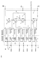
- FIG. 1 is an overall circuit block diagram of the power conversion control device 100 according to the first embodiment.
- FIG. 2 is a schematic view showing an example of an insulated power supply in the power conversion control device 100.
- the low voltage side using the low voltage battery 1 as a power source and the high voltage side using the high voltage battery 2 as a power source are electrically isolated, and the power conversion control device 100 is a constant voltage circuit 3 It is composed of a processing unit 4, gate drive circuits 5a to 5f, isolated power supplies 6a to 6f, gate isolated transistors 7a to 7f, an insulated communication circuit 8, and a voltage measuring circuit 9.
- the three-phase motor drive circuit 7 is composed of gate-insulated transistors 7a to 7f.
- the low voltage side of the power conversion control device 100 may be connected to a low voltage power source generated by step-down from the high voltage battery 2.
- sensors such as a temperature sensor and a current sensor, other control circuits, and the like may be connected as needed.
- the low-voltage battery 1 which is the power source on the low-voltage side, is connected to the power conversion control device 100 via the switch 10, and is connected to the constant voltage circuit 3 and the isolated power supplies 6a to 6f inside the power conversion control device 100. There is.
- the constant voltage circuit 3 and the insulated power supplies 6a to 6f may not be directly connected but may be connected via a diode or a coil.
- the constant voltage circuit 3 controls the electric power supplied from the low voltage battery 1 so as to have a predetermined voltage, and outputs the electric power from the output terminal.
- the output terminal of the constant voltage circuit 3 is connected to the power supply terminal of the processing unit 4, the low voltage side power supply terminal of the gate drive circuits 5a to 5f, and the low voltage side power supply terminal of the insulation communication circuit 8.
- the voltage circuit 3 is used as a power source for each of the processing unit 4, the gate drive circuits 5a to 5f, and the isolated communication circuit 8.
- the low-voltage side power supplies of the gate drive circuits 5a to 5f and the power supply of the insulation communication circuit 8 may be configured to be directly supplied from, for example, the low-voltage battery 1 without going through the constant voltage circuit 3.
- the insulated power supplies 6a to 6f form a power supply that is electrically isolated from the low voltage side by DC-DC conversion of the power applied to the power supply terminals, and outputs the power to the high voltage side.
- the configuration of the flyback type switching power supply is shown as an example of the insulated power supplies 6a to 6f, but other methods such as a forward type or a full bridge type may be used.
- the insulated power supplies 6a to 6b have so-called enable terminals EN1 to EN6 that determine whether or not the operation as a power supply circuit is valid, are connected to the processing unit 4, and are connected to the processing unit 4 by a control signal from the processing unit 4.
- the operation as a power source can be controlled arbitrarily.
- the output terminals HVOUT1 to HVOUT6 of the insulated power supplies 6a to 6f are connected to the high voltage side power supply terminals HVCC1 to HVCC6 of the gate drive circuits 5a to 5f, and are used as power supplies for the gate drive circuits 5a to 5f.
- Gate drive signals from the processing unit 4 are input to terminals IN1 to IN6, which are input units of the gate drive circuits 5a to 5f.
- the gate drive circuits 5a to 5f output from the terminals OUT1 to OUT6 according to the gate drive signals input from the terminals IN1 to IN6.
- the three-phase motor drive circuit 7 is connected to the high-voltage battery 2 via switches 11a and 11b such as a relay, and uses the electric power obtained from the high-voltage battery 2 as a power source and outputs the power from the gate drive circuits 5a to 5f.
- DC-AC conversion is performed by intermittent operation based on the signal, and power is supplied to the three-phase motor 12 connected to the outside of the power conversion control device 100.
- the processing unit 4 on the low voltage side converts the DC power on the high voltage side into AC power, or converts the AC power generated from the three-phase motor 12 into DC power.
- the gate-insulated transistor 7a for driving the three-phase motor. Controls up to 7f.
- FIG. 2 shows an example of an insulated power supply, and the configuration thereof will be described in detail.
- the insulated power supply 6 is shown as a representative of the insulated power supplies 6a to 6f in FIG. 1, and is mainly composed of a transformer 61, a transistor 62, and an insulated power supply circuit 60 including an output voltage monitoring circuit. ing.
- the insulated power supply circuit 60 is composed of a control unit 601, a backflow prevention diode 602, a capacitor 603, an addition / subtraction unit 604, and a determination unit 605.
- the isolated power supply 6 is electrically insulated from the low voltage side and the high voltage side by the transformer 61 and the insulated power supply circuit 60, and the output voltage is transmitted to the outside, so that the output voltage is stably output. It has become like.
- the low voltage side is charged by the induced energy generated in the transformer 61 when the transistor 62 is intermittently driven, via the backflow prevention diode 602 included in the insulated power supply circuit 60, and by the capacitor 603. Power is supplied from the high voltage side to the high voltage side.
- the isolated power supply has an isolated power supply circuit in which power is supplied from a low-voltage battery or a low-voltage power supply, a transformer that converts power from the low-voltage side to the high-voltage side, and a transistor that controls the transformer. It operates by being supplied with power from a voltage battery or a low-voltage power supply, and stops the power supply according to the instructions of the processing unit.
- the power supply supplied to the three-phase motor drive circuit 7 is detected by the voltage measurement circuit 9, and the detected signal is input to the input terminal IN of the insulation communication circuit 8, and an analog signal or a digital signal is input based on the input signal. Is output from the low voltage side output terminal OUT and input to the processing unit 4.
- the voltage measurement circuit 9 measures the input voltage to the three-phase motor drive circuit 7 in order to control the AC power supplied to the three-phase motor while the vehicle is running.
- the power supply terminal VCS-I on the high voltage side of the insulation communication circuit 8 is supplied with power from at least one of the insulation power supplies 6a to 6f.
- the output terminal HVOUT6 of the insulation power supply 6f for the gate drive circuit 5f is supplied.
- a plurality of insulated power supplies 6e and 6f may be shared and connected to the power supply terminal VCS-I of the insulated communication circuit 8 to supply power.
- the operation of the power conversion control device 100 according to the first embodiment will be described.
- the gate-insulated transistor when the gate-insulated transistor is not in the switching operation except when the vehicle is stopped or when the vehicle is stopped, such as when the high-voltage battery is being charged, and the voltage of the high-voltage battery needs to be monitored. Also, at least one of the isolated power supplies can be operated, and the voltage of the high voltage battery can be measured by the voltage measuring circuit 9.
- power is supplied to the isolated communication circuit 8 by transmitting an operation valid signal from the processing unit 4 to the enable terminal EN6 of the insulated power supply 6f of the EN-WL phase. At this time, by disabling the operation of the other insulated power source, it is possible to suppress the consumption of the power supplied from the low voltage battery 1. Further, by short-circuiting the switch 11a and the switch 11b by an external control device (not shown), power is supplied from the high voltage battery 2 to the power conversion control device 100, and the voltage of the high voltage battery 2 is applied by the voltage measuring circuit 9. It becomes possible to measure.
- the low voltage side connected to the high voltage battery used as the drive power source of the electric vehicle and the low voltage side generated from the low voltage battery or the high voltage battery used as the control power source of the electric vehicle are step-down generated.
- the low voltage side connected to the voltage power supply is electrically insulated, and the processing unit on the low voltage side converts the DC power on the high voltage side to AC power, or the AC power generated from the three-phase motor to DC power. It is a power conversion control device that controls a gate-isolated transistor for driving a three-phase motor.
- the low voltage side includes a constant voltage circuit in which power is supplied from a low voltage battery or a low voltage power source, and a processing unit in which power is supplied with constant voltage from the constant voltage circuit.
- a three-phase motor drive circuit having a plurality of gate-isolated transistors that convert DC power obtained from the high voltage battery into AC power, and a voltage measurement circuit that measures the voltage of the high voltage battery. And have.
- a plurality of isolated power supplies that are supplied from a low-voltage battery or a low-voltage power supply and output a constant voltage to the high-voltage side, and a gate-isolated transistor, which are arranged across the low-voltage side and the high-voltage side.
- It is a power conversion control device including a gate drive circuit that controls a gate in response to a command from the low voltage side, and an isolated communication circuit that insulates and transmits the measured value of the voltage measurement circuit to the low voltage side. Further, each pair of insulated power supplies is connected to the gate drive circuit, and the low voltage side of the isolated communication circuit is supplied with constant voltage power from the low voltage battery via the constant voltage circuit for isolated communication. The high voltage side of the circuit operates at least one of the isolated power supplies, and insulates and transmits the voltage signal of the high voltage battery from the high voltage side to the low voltage side. In addition, the operation of the insulated power supply is stopped by the command of the processing unit.
- the operation of the insulated power supply is individually enabled and disabled by the control of the processing unit, so that the high voltage is suppressed while the consumption of the power supplied from the low voltage battery is suppressed. It is possible to monitor the voltage of the battery, and it is possible to obtain a power conversion control device for an electric vehicle that is small, inexpensive, and has low current consumption.
- the insulated power supply of the insulated communication circuit also serves as the insulated power supply for the gate drive circuit, it can be configured compactly and inexpensively, and the insulated power supply for the gate drive circuit that is also used is the upper and lower all phases. It can be standardized as the same as the gate power supply circuit. Since the current consumption of the insulated power supply of the insulated communication circuit is overwhelmingly smaller than the gate drive current supplied from the insulated power supply for the gate drive circuit, the insulated power supply for the gate drive circuit is insulated for the insulated communication circuit. Even if it is also used as a power source, the power consumption of the insulated power source for the gate drive circuit during operation does not substantially increase, and the cost does not increase.
- the power consumption of the insulated power supply for the insulated communication circuit is small, the components such as the insulated circuit and the constant voltage control are the same as the insulated power supply for the gate drive circuit, and the power supply for the insulated communication circuit is provided separately. There is a burden on both the cost and the mounting space. Therefore, in the power conversion control device according to the present application, by using one of the insulated power supplies for the gate drive circuit as the insulated power supply for the insulated communication circuit, there is an effect that both cost and mounting space can be saved. Further, in the power conversion control device according to the first embodiment, the voltage of the high voltage battery can be monitored by diverting the insulated power source even when the vehicle is stopped such as during charging of the high voltage battery.
- FIG. 4 is an overall circuit block diagram of the power conversion control device 100 according to the second embodiment.
- the three-phase motor drive circuit 7 uses the electric power supplied from the high-voltage battery 2 as a power source, but the three-phase motor drive circuit 7 in the second embodiment is obtained from the high-voltage battery 2.
- the electric power boosted by the booster circuit 13 is used as a power source.
- the insulated power source for operating the insulated communication circuit 8 is provided in the booster circuit 13 for boosting the voltage of the high voltage battery 2.
- FIG. 5 shows an example of the booster circuit 13.
- the booster circuit 13 includes an insulated power supply 6 g to an insulated power supply 6j, a gate drive circuit 5 g to a gate drive circuit 5j, a gate isolated transistor 7 g to a gate insulated transistor 7j, an exciting element 14, and a smoothing capacitor 15.
- the capacitor 16 and the capacitor 17 are mainly configured.
- Insulated power supply 6g to insulated power supply 6j and gate drive circuit 5g to gate drive circuit 5j are electrically insulated on the low voltage side and high voltage side to intermittently drive the gate isolated transistor 7g to the gate isolated transistor 7j. By doing so, the induced energy generated from the exciting element 14 is charged to the smoothing capacitor 15, thereby boosting the voltage.
- this booster circuit 13 is a switched capacitor type DCDC converter and is generally used, the description of its operation is omitted, but the gate drive circuit 5g to the gate drive circuit 5j and the isolated power supply 6g to the insulated power supply It is configured to include 6j, and four are connected in series.
- the power supply terminal VCC-I on the high voltage side of the insulated communication circuit 8 is supplied with power from the output terminal HVOUT6 of the insulated power supply 6f for the gate drive circuit 5f, but in the second embodiment
- the power supply terminal VCS-I on the high voltage side of the insulation communication circuit 8 is connected to the output terminal HVOUT10 of the insulation power supply 6j for the gate drive circuit 5j in the lowermost layer of the booster circuit 13, and the power supply is supplied from this output terminal HVOUT10. It is being supplied.
- the insulated power supply for measurement also serves as one of the insulated power supplies for gate driving, and the other insulated power supply for gate driving that is not operating is based on the signal from the processing unit 4. Since the operation can be invalidated, it is possible to obtain a power conversion control device for a small, inexpensive, and low current consumption electric vehicle.
- the processing unit 4 is composed of a processor 400 and a storage device 401, as shown in FIG. 5 as an example of hardware.
- the storage device 401 includes, for example, a volatile storage device such as a random access memory and a non-volatile auxiliary storage device such as a flash memory. Further, an auxiliary storage device of a hard disk may be provided instead of the flash memory.
- the processor 400 executes the program input from the storage device 401. In this case, a program is input from the auxiliary storage device to the processor 400 via the volatile storage device. Further, the processor 400 may output data such as a calculation result to the volatile storage device of the storage device 401, or may store the data in the auxiliary storage device via the volatile storage device.
Abstract
小型、安価で低消費電流である電動車両の電力変換制御装置を得る。ゲート駆動回路(5a)~(5f)には一対となるそれぞれの絶縁電源(6a)~(6f)が接続されていて、絶縁通信回路(8)の低電圧側は低電圧バッテリ(1)から定電圧回路(3)を介して定電圧化された電力が供給され、絶縁通信回路(8)の高電圧側は絶縁電源(6a)~(6f)の内の少なくともひとつである絶縁電源(6f)で動作させ、高電圧バッテリ(2)の電圧信号を高電圧側から低電圧側に絶縁して送信する。
Description
本願は、電動車両に用いられる電力変換制御装置に関するものである。
一般に、電気自動車あるいはハイブリッド自動車等の電動車両は、車両の駆動源として交流回転電機を搭載している。この交流回転電機は電力変換制御装置によって電力が供給される。
この電力変換制御装置は、低電圧バッテリを電源とする車両の制御に関する制御回路と、高電圧バッテリを電源とする車両の駆動に関する駆動回路とが、電気的に絶縁されている。
この電力変換制御装置は、低電圧バッテリを電源とする車両の制御に関する制御回路と、高電圧バッテリを電源とする車両の駆動に関する駆動回路とが、電気的に絶縁されている。
絶縁された低電圧側の制御回路と高電圧側の駆動回路との間で信号の伝達を行うためには、電気的に低電圧側と高電圧側とを通信させるための絶縁通信回路を設ける必要がある。絶縁通信回路の低電圧側と高電圧側には、それぞれ絶縁された電源が必要となるので、絶縁電源の電源供給元である低電圧電源と高電圧電源との間であらかじめ決められた絶縁距離を確保する必要があるため、電力変換制御装置自体が大型化する要因となっている。
上記の問題点を解決するための手段として、下記の特許文献1では、電源、電源生成回路等を必要最小限に冗長化しつつ、異常発生時のシステムを確実に保護することが提案されている。
例えば、特許文献1では、絶縁電源を流用することが示されている。絶縁電源の電源供給経路が二手に分岐し、供給先である放電用駆動回路と下アーム側駆動回路において電源が流用され、絶縁電源の冗長化を実現している。
例えば、特許文献1では、絶縁電源を流用することが示されている。絶縁電源の電源供給経路が二手に分岐し、供給先である放電用駆動回路と下アーム側駆動回路において電源が流用され、絶縁電源の冗長化を実現している。
しかしながら、特許文献1では、絶縁電源の個別動作に関して言及されておらず、省電力化、小型化、低コスト化に対しての配慮が十分とは言えず改善の余地がある。
本願は、上記のような問題点を解決するためになされたものであり、小型、安価で低消費電流の電力変換制御装置を提供するものである。
本願に開示される電力変換制御装置は、電動車両の駆動電源として用いられる高電圧バッテリに接続された高電圧側と電動車両の制御電源として用いられる低電圧バッテリもしくは高電圧バッテリから降圧生成される低電圧電源に接続された低電圧側は電気的に絶縁され、低電圧側にある処理部は高電圧側の直流電力を交流電力に変換、もしくは三相モータから発生する交流電力を直流電力に変換する三相モータ駆動用のゲート絶縁型トランジスタの制御を行う電力変換制御装置であって、低電圧側には、低電圧バッテリまたは低電圧電源から電力が供給される定電圧回路と、定電圧回路から定電圧化された電力が供給される処理部と、を備え、高電圧側には、高電圧バッテリから得られた直流電力から交流電力に変換する複数のゲート絶縁型トランジスタを有した三相モータ駆動回路と、高電圧バッテリの電圧を計測する電圧計測回路と、を備え、低電圧側と高電圧側の間に跨って配置される、低電圧バッテリまたは低電圧電源から電力供給され、高電圧側に定電圧を出力する複数の絶縁電源と、ゲート絶縁型トランジスタを低電圧側からの指令に応じてゲートを制御するゲート駆動回路と、電圧計測回路の計測値を低電圧側に絶縁して送信する絶縁通信回路と、を備えた電力変換制御装置において、ゲート駆動回路には一対となるそれぞれの絶縁電源が接続されていて、絶縁通信回路の低電圧側は低電圧バッテリから定電圧回路を介して定電圧化された電力が供給され、絶縁通信回路の高電圧側は絶縁電源の少なくともひとつで動作させ、高電圧バッテリの電圧信号を高電圧側から低電圧側に絶縁して送信するものである。
本願に開示される電力変換制御装置によれば、絶縁通信回路の絶縁電源をゲート駆動回路の絶縁電源で兼用できるので、小型、安価に構成することができ、低消費電流の電力変換制御装置を得ることができる。
以下、電力変換制御装置の実施の形態について図に基づいて説明する。各図において、同一または相当部分については、同一符号を付して説明している。
実施の形態1.
図1は、実施の形態1による電力変換制御装置100の全体回路ブロック図である。図2は、電力変換制御装置100における絶縁電源の一例を示す概略図である。
図1において、低電圧バッテリ1を電源とする低電圧側と、高電圧バッテリ2を電源とする高電圧側とは、電気的に絶縁されており、電力変換制御装置100は、定電圧回路3と、処理部4と、ゲート駆動回路5a~5fと、絶縁電源6a~6fと、ゲート絶縁型トランジスタ7a~7fと、絶縁通信回路8と、電圧計測回路9と、により構成されている。ゲート絶縁型トランジスタ7a~7fによって三相モータ駆動回路7を構成している。
また、電力変換制御装置100の低電圧側は、高電圧バッテリ2から降圧生成される低電圧電源に接続してもよい。
なお、図1には図示していないが、必要に応じ温度センサ、電流センサ等のセンサ類、他の制御回路等が接続されていても構わない。
低電圧側の電源である低電圧バッテリ1は、スイッチ10を介し電力変換制御装置100に接続され、電力変換制御装置100の内部では定電圧回路3と、絶縁電源6a~6fとに接続されている。
なお、定電圧回路3と絶縁電源6a~6fとは、直接接続せずに、ダイオード、コイルを介して接続しても構わない。
なお、定電圧回路3と絶縁電源6a~6fとは、直接接続せずに、ダイオード、コイルを介して接続しても構わない。
定電圧回路3は、低電圧バッテリ1から供給された電力を、予め決められた電圧となるよう制御し、出力端子から出力する。
定電圧回路3の出力端子は、処理部4の電源端子と、ゲート駆動回路5a~5fの低電圧側電源端子と、絶縁通信回路8の低電圧側電源端子と、に接続されており、定電圧回路3は、処理部4、ゲート駆動回路5a~5f、絶縁通信回路8のそれぞれの電源として使用されている。
ゲート駆動回路5a~5fの低電圧側電源と、絶縁通信回路8の電源は、定電圧回路3を介さずに、例えば、低電圧バッテリ1から直接供給される構成であっても構わない。
定電圧回路3の出力端子は、処理部4の電源端子と、ゲート駆動回路5a~5fの低電圧側電源端子と、絶縁通信回路8の低電圧側電源端子と、に接続されており、定電圧回路3は、処理部4、ゲート駆動回路5a~5f、絶縁通信回路8のそれぞれの電源として使用されている。
ゲート駆動回路5a~5fの低電圧側電源と、絶縁通信回路8の電源は、定電圧回路3を介さずに、例えば、低電圧バッテリ1から直接供給される構成であっても構わない。
一方、絶縁電源6a~6fは、電源端子に印加された電力をDC-DC変換により、低電圧側から電気的に絶縁された電源を構成し、高電圧側に出力する構成となっている。
絶縁電源6a~6fの一例としてフライバック方式のスイッチング電源の構成を示すが、フォワード方式あるいはフルブリッジ方式等の他の方式であっても構わない。
絶縁電源6a~6fの一例としてフライバック方式のスイッチング電源の構成を示すが、フォワード方式あるいはフルブリッジ方式等の他の方式であっても構わない。
絶縁電源6a~6bは、電源回路としての動作を有効とするか否かを決定する、いわゆるイネーブル端子EN1~EN6を有し、処理部4に接続されており、処理部4からの制御信号によって電源としての動作を任意に制御することができる。
絶縁電源6a~6fの出力端子HVOUT1~HVOUT6は、ゲート駆動回路5a~5fの高電圧側電源端子HVCC1~HVCC6に接続され、ゲート駆動回路5a~5fの電源として使用されている。
ゲート駆動回路5a~5fの入力部である端子IN1~IN6は、処理部4からのゲート駆動信号が入力される。
ゲート駆動回路5a~5fは、各端子IN1~IN6から入力されるゲート駆動信号に応じて、端子OUT1~OUT6から出力を行う。
ゲート駆動回路5a~5fは、各端子IN1~IN6から入力されるゲート駆動信号に応じて、端子OUT1~OUT6から出力を行う。
三相モータ駆動回路7は、リレー等のスイッチ11a、11bを介し、高電圧バッテリ2に接続されており、高電圧バッテリ2から得られる電力を電源とし、ゲート駆動回路5a~5fから出力される信号に基づき断続動作することでDC-AC変換を行い、電力変換制御装置100の外部に接続されている三相モータ12に電力を供給する。
なお、低電圧側にある処理部4は高電圧側の直流電力を交流電力に変換、もしくは三相モータ12から発生する交流電力を直流電力に変換する三相モータ駆動用のゲート絶縁型トランジスタ7a~7fの制御を行う。
なお、低電圧側にある処理部4は高電圧側の直流電力を交流電力に変換、もしくは三相モータ12から発生する交流電力を直流電力に変換する三相モータ駆動用のゲート絶縁型トランジスタ7a~7fの制御を行う。
図2は、絶縁電源の一例を示しており、その構成を詳細に説明する。
図2において、絶縁電源6は、図1における絶縁電源6a~6fを代表して示しており、トランス61と、トランジスタ62と、出力電圧監視回路を含む絶縁電源回路60とを、主体として構成されている。なお、絶縁電源回路60は、制御部601、逆流防止ダイオード602、コンデンサ603、加減算部604、判定部605で構成されている。
図2において、絶縁電源6は、図1における絶縁電源6a~6fを代表して示しており、トランス61と、トランジスタ62と、出力電圧監視回路を含む絶縁電源回路60とを、主体として構成されている。なお、絶縁電源回路60は、制御部601、逆流防止ダイオード602、コンデンサ603、加減算部604、判定部605で構成されている。
この絶縁電源6は、トランス61と、絶縁電源回路60により、低電圧側と高電圧側とが電気的に絶縁されて出力電圧を外部へ送信することで、出力電圧を安定して出力されるようになっている。
絶縁電源回路60においては、トランジスタ62を断続駆動したときにトランス61に発生する誘導エネルギによって、絶縁電源回路60に含まれる逆流防止ダイオード602を介して、充電されるコンデンサ603とによって、低電圧側から高電圧側へと電力を供給されるようになっている。
絶縁電源は、低電圧バッテリまたは低電圧電源から電力が供給される絶縁電源回路と、低電圧側から高電圧側に電力変換するトランスと、トランスを制御するトランジスタとを有し、トランジスタは、低電圧バッテリまたは低電圧電源から電力供給されることにより動作し、処理部の指示により、電力供給を停止させる。
絶縁電源回路60においては、トランジスタ62を断続駆動したときにトランス61に発生する誘導エネルギによって、絶縁電源回路60に含まれる逆流防止ダイオード602を介して、充電されるコンデンサ603とによって、低電圧側から高電圧側へと電力を供給されるようになっている。
絶縁電源は、低電圧バッテリまたは低電圧電源から電力が供給される絶縁電源回路と、低電圧側から高電圧側に電力変換するトランスと、トランスを制御するトランジスタとを有し、トランジスタは、低電圧バッテリまたは低電圧電源から電力供給されることにより動作し、処理部の指示により、電力供給を停止させる。
三相モータ駆動回路7に供給される電源は、電圧計測回路9により検出され、検出された信号は絶縁通信回路8の入力端子INに入力され、入力された信号に基づき、アナログ信号またはデジタル信号として低電圧側出力端子OUTから出力され、処理部4へ入力される。
電圧計測回路9は車両走行中に、三相モータに供給する交流電力の制御を行うため、三相モータ駆動回路7への入力電圧を計測するものである。
絶縁通信回路8の高電圧側の電源端子VCC-Iは、絶縁電源6a~6fの内の少なくともひとつから電源が供給されており、図1ではゲート駆動回路5f用の絶縁電源6fの出力端子HVOUT6を絶縁通信回路8の電源端子VCC-Iに接続し電源供給しているが,例えば、他のゲート駆動回路用の絶縁電源から供給しても構わない。さらに、図3に示すように、複数の絶縁電源6e、絶縁電源6fを共用して絶縁通信回路8の電源端子VCC-Iに接続し電源供給しても構わない。
但し、基準電位を同一とすることが可能ないずれかのゲート駆動回路用の絶縁電源を、絶縁通信回路8の電源として供給することが望ましい。
但し、基準電位を同一とすることが可能ないずれかのゲート駆動回路用の絶縁電源を、絶縁通信回路8の電源として供給することが望ましい。
次に、この実施の形態1による電力変換制御装置100の動作について説明する。
本実施形態においては、高電圧バッテリの充電中等の、車両停止時、または車両停止時以外のゲート絶縁型トランジスタがスイッチング動作していないときであって、且つ高電圧バッテリの電圧監視が必要な場合においても、絶縁電源の少なくとも一つを動作させ、電圧計測回路9により高電圧バッテリの電圧を計測することができる。
本実施形態においては、高電圧バッテリの充電中等の、車両停止時、または車両停止時以外のゲート絶縁型トランジスタがスイッチング動作していないときであって、且つ高電圧バッテリの電圧監視が必要な場合においても、絶縁電源の少なくとも一つを動作させ、電圧計測回路9により高電圧バッテリの電圧を計測することができる。
ここで、処理部4からEN-WL相の絶縁電源6fのイネーブル端子EN6に動作有効信号を伝達することで、絶縁通信回路8に電力が供給される。
この際、他の絶縁電源の動作を無効とすることで低電圧バッテリ1から供給される電力の消費を抑制することが可能となる。
また、図示しない外部の制御装置によりスイッチ11a、スイッチ11bを短絡状態とすることで、電力変換制御装置100に高電圧バッテリ2から電力が供給され電圧計測回路9にて高電圧バッテリ2の電圧を測定することが可能となる。
この際、他の絶縁電源の動作を無効とすることで低電圧バッテリ1から供給される電力の消費を抑制することが可能となる。
また、図示しない外部の制御装置によりスイッチ11a、スイッチ11bを短絡状態とすることで、電力変換制御装置100に高電圧バッテリ2から電力が供給され電圧計測回路9にて高電圧バッテリ2の電圧を測定することが可能となる。
このように、実施の形態1は、電動車両の駆動電源として用いられる高電圧バッテリに接続された高電圧側と電動車両の制御電源として用いられる低電圧バッテリもしくは高電圧バッテリから降圧生成される低電圧電源に接続された低電圧側は電気的に絶縁され、低電圧側にある処理部は高電圧側の直流電力を交流電力に変換、もしくは三相モータから発生する交流電力を直流電力に変換する三相モータ駆動用のゲート絶縁型トランジスタの制御を行う電力変換制御装置である。また、低電圧側には、低電圧バッテリまたは低電圧電源から電力が供給される定電圧回路と、定電圧回路から定電圧化された電力が供給される処理部と、を備えている。さらに、高電圧側には、高電圧バッテリから得られた直流電力から交流電力に変換する複数のゲート絶縁型トランジスタを有した三相モータ駆動回路と、高電圧バッテリの電圧を計測する電圧計測回路と、を備えている。また、低電圧側と高電圧側の間に跨って配置される、低電圧バッテリまたは低電圧電源から電力供給され、高電圧側に定電圧を出力する複数の絶縁電源と、ゲート絶縁型トランジスタを低電圧側からの指令に応じてゲートを制御するゲート駆動回路と、電圧計測回路の計測値を低電圧側に絶縁して送信する絶縁通信回路と、を備えた電力変換制御装置である。さらに、ゲート駆動回路には一対となるそれぞれの絶縁電源が接続されていて、絶縁通信回路の低電圧側は低電圧バッテリから定電圧回路を介して定電圧化された電力が供給され、絶縁通信回路の高電圧側は絶縁電源の少なくともひとつを動作させ、高電圧バッテリの電圧信号を前記高電圧側から低電圧側に絶縁して送信する。また、処理部の指令により絶縁電源を動作停止させる。
以上のように、実施の形態1によれば、処理部の制御により絶縁電源の動作を個別に有効、無効とすることで、低電圧バッテリから供給される電力の消費を抑制した状態で高電圧バッテリを電圧監視することが可能となり、小型、安価で低消費電流の電動車両の電力変換制御装置を得ることができる。
また、絶縁通信回路の絶縁電源は、ゲート駆動回路用の絶縁電源を兼用しているので、小型、安価に構成することができ、兼用されたゲート駆動回路用の絶縁電源は、上下全相のゲート電源回路と同一物として標準化することができる。
絶縁通信回路の絶縁電源の消費電流は、ゲート駆動回路用の絶縁電源から給電されるゲート駆動電流に比べて圧倒的に微小であるため、ゲート駆動回路用の絶縁電源を絶縁通信回路用の絶縁電源として兼用しても、運転中におけるゲート駆動回路用の絶縁電源の消費電力は実質的に増加せず、コストアップしない。
また、絶縁通信回路用の絶縁電源の消費電力は小さいといえども、絶縁回路と定電圧制御などの構成要素はゲート駆動回路用の絶縁電源と同一であり、絶縁通信回路用電源を個別に設けるとコスト、取付スペースの両面で負担が生じる。したがって、本願による電力変換制御装置では、絶縁通信回路用の絶縁電源にゲート駆動回路用の絶縁電源の一つを兼用することで、コスト、取付スペースの両面を節約できる効果がある。
さらに、実施の形態1による電力変換制御装置では、高電圧バッテリの充電中等の車両停止においても、絶縁電源を流用し高電圧バッテリの電圧監視を行うことができる。
実施の形態2.
図4は実施の形態2による電力変換制御装置100の全体回路ブロック図である。
図4において、図1と同一符号は同一、または相当部分を示すため、その説明を省略する。
上述の実施の形態1では、三相モータ駆動回路7は高電圧バッテリ2から供給される電力を電源としていたが、この実施の形態2における三相モータ駆動回路7は高電圧バッテリ2から得られる電力を、昇圧回路13によって昇圧された電力を電源として使用している。
また、絶縁通信回路8を動作させる絶縁電源は、高電圧バッテリ2の電圧を昇圧する昇圧回路13に備えられている。
図4は実施の形態2による電力変換制御装置100の全体回路ブロック図である。
図4において、図1と同一符号は同一、または相当部分を示すため、その説明を省略する。
上述の実施の形態1では、三相モータ駆動回路7は高電圧バッテリ2から供給される電力を電源としていたが、この実施の形態2における三相モータ駆動回路7は高電圧バッテリ2から得られる電力を、昇圧回路13によって昇圧された電力を電源として使用している。
また、絶縁通信回路8を動作させる絶縁電源は、高電圧バッテリ2の電圧を昇圧する昇圧回路13に備えられている。
図5は昇圧回路13の一例を示している。
図5において、昇圧回路13は、絶縁電源6g~絶縁電源6jと、ゲート駆動回路5g~ゲート駆動回路5jと、ゲート絶縁型トランジスタ7g~ゲート絶縁型トランジスタ7jと、励磁素子14と、平滑コンデンサ15と、コンデンサ16、コンデンサ17とを、主体として構成されている。絶縁電源6g~絶縁電源6jと、ゲート駆動回路5g~ゲート駆動回路5jにより、低電圧側と高電圧側とに、電気的に絶縁されてゲート絶縁型トランジスタ7g~ゲート絶縁型トランジスタ7jを断続駆動することで、励磁素子14から発生する誘導エネルギが平滑コンデンサ15へ充電されることで、昇圧を行う。
図5において、昇圧回路13は、絶縁電源6g~絶縁電源6jと、ゲート駆動回路5g~ゲート駆動回路5jと、ゲート絶縁型トランジスタ7g~ゲート絶縁型トランジスタ7jと、励磁素子14と、平滑コンデンサ15と、コンデンサ16、コンデンサ17とを、主体として構成されている。絶縁電源6g~絶縁電源6jと、ゲート駆動回路5g~ゲート駆動回路5jにより、低電圧側と高電圧側とに、電気的に絶縁されてゲート絶縁型トランジスタ7g~ゲート絶縁型トランジスタ7jを断続駆動することで、励磁素子14から発生する誘導エネルギが平滑コンデンサ15へ充電されることで、昇圧を行う。
この昇圧回路13はスイッチドキャパシタ式DCDCコンバータであり、一般的に使用されるものであるため、その動作についての説明は省略するがゲート駆動回路5g~ゲート駆動回路5jと絶縁電源6g~絶縁電源6jとを含み構成されており、直列に4つ接続されている。
実施の形態1では、絶縁通信回路8の高電圧側の電源端子VCC-Iは、ゲート駆動回路5f用の絶縁電源6fの出力端子HVOUT6から電源が供給されていたが、この実施の形態2では、絶縁通信回路8の高電圧側の電源端子VCC-Iは、昇圧回路13の最下層のゲート駆動回路5j用の絶縁電源6jの出力端子HVOUT10に接続されており、この出力端子HVOUT10から電源が供給されている。
以上のことから、実施の形態2においても計測用の絶縁電源はゲート駆動用の絶縁電源の一つを兼用し作動していない他のゲート駆動用の絶縁電源は処理部4からの信号によりその動作を無効とすることができるので、小型、安価で低消費電流の電動車両の電力変換制御装置を得ることができる。
以上のことから、実施の形態2においても計測用の絶縁電源はゲート駆動用の絶縁電源の一つを兼用し作動していない他のゲート駆動用の絶縁電源は処理部4からの信号によりその動作を無効とすることができるので、小型、安価で低消費電流の電動車両の電力変換制御装置を得ることができる。
なお、処理部4は、ハードウエアの一例を図5に示すように、プロセッサ400と記憶装置401から構成される。記憶装置401は、例えば、ランダムアクセスメモリ等の揮発性記憶装置と、フラッシュメモリ等の不揮発性の補助記憶装置とを具備する。また、フラッシュメモリの代わりにハードディスクの補助記憶装置を具備してもよい。プロセッサ400は、記憶装置401から入力されたプログラムを実行する。この場合、補助記憶装置から揮発性記憶装置を介してプロセッサ400にプログラムが入力される。また、プロセッサ400は、演算結果等のデータを記憶装置401の揮発性記憶装置に出力してもよいし、揮発性記憶装置を介して補助記憶装置にデータを保存してもよい。
本願は、様々な例示的な実施の形態及び実施例が記載されているが、1つ、または複数の実施の形態に記載された様々な特徴、態様、及び機能は特定の実施の形態の適用に限られるのではなく、単独で、または様々な組み合わせで実施の形態に適用可能である。
従って、例示されていない無数の変形例が、本願明細書に開示される技術の範囲内において想定される。例えば、少なくとも1つの構成要素を変形する場合、追加する場合または省略する場合、さらには、少なくとも1つの構成要素を抽出し、他の実施の形態の構成要素と組み合わせる場合が含まれるものとする。
従って、例示されていない無数の変形例が、本願明細書に開示される技術の範囲内において想定される。例えば、少なくとも1つの構成要素を変形する場合、追加する場合または省略する場合、さらには、少なくとも1つの構成要素を抽出し、他の実施の形態の構成要素と組み合わせる場合が含まれるものとする。
1 低電圧バッテリ、2 高電圧バッテリ、3 定電圧回路、4 処理部、5a~5j ゲート駆動回路、6,6a~6j 絶縁電源、7 三相モータ駆動回路、7a~7j ゲート絶縁型トランジスタ、8 絶縁通信回路、9 電圧計測回路、13 昇圧回路、100 電力変換制御装置
Claims (4)
- 電動車両の駆動電源として用いられる高電圧バッテリに接続された高電圧側と前記電動車両の制御電源として用いられる低電圧バッテリもしくは前記高電圧バッテリから降圧生成される低電圧電源に接続された低電圧側は電気的に絶縁され、前記低電圧側にある処理部は前記高電圧側の直流電力を交流電力に変換、もしくは三相モータから発生する交流電力を直流電力に変換する三相モータ駆動用のゲート絶縁型トランジスタの制御を行う電力変換制御装置であって、前記低電圧側には、前記低電圧バッテリまたは前記低電圧電源から電力が供給される定電圧回路と、前記定電圧回路から定電圧化された電力が供給される前記処理部と、を備え、前記高電圧側には、前記高電圧バッテリから得られた直流電力から交流電力に変換する複数のゲート絶縁型トランジスタを有した三相モータ駆動回路と、前記高電圧バッテリの電圧を計測する電圧計測回路と、を備え、前記低電圧側と前記高電圧側の間に跨って配置される、前記低電圧バッテリまたは前記低電圧電源から電力供給され、前記高電圧側に定電圧を出力する複数の絶縁電源と、前記ゲート絶縁型トランジスタを前記低電圧側からの指令に応じてゲートを制御するゲート駆動回路と、前記電圧計測回路の計測値を前記低電圧側に絶縁して送信する絶縁通信回路と、を備えた電力変換制御装置において、前記ゲート駆動回路には一対となる前記絶縁電源が接続されていて、前記絶縁通信回路の前記低電圧側は前記低電圧バッテリから前記定電圧回路を介して定電圧化された電力が供給され、前記絶縁通信回路の前記高電圧側は前記絶縁電源の少なくともひとつで動作させ、前記高電圧バッテリの電圧信号を前記高電圧側から前記低電圧側に絶縁して送信することを特徴とする電力変換制御装置。
- 前記絶縁通信回路を動作させる前記絶縁電源は、前記高電圧バッテリの電圧を昇圧する昇圧回路に備えられていることを特徴とする請求項1に記載の電力変換制御装置。
- 前記処理部の指令により前記絶縁電源を動作停止させることを特徴とする請求項1または請求項2に記載の電力変換制御装置。
- 前記絶縁電源は、前記低電圧バッテリまたは前記低電圧電源から電力が供給される絶縁電源回路と、前記低電圧側から前記高電圧側に電力変換するトランスと、前記トランスを制御するトランジスタとを有し、前記トランジスタは、前記低電圧バッテリまたは前記低電圧電源から電力供給されることにより動作し、前記処理部の指示により、電力供給を停止させることを特徴とする請求項3に記載の電力変換制御装置。
Priority Applications (5)
| Application Number | Priority Date | Filing Date | Title |
|---|---|---|---|
| DE112019007650.7T DE112019007650T8 (de) | 2019-08-23 | 2019-08-23 | Leistungswandlungsregelvorrichtung |
| CN201980098118.3A CN114223126A (zh) | 2019-08-23 | 2019-08-23 | 功率转换控制装置 |
| US17/633,433 US20220294364A1 (en) | 2019-08-23 | 2019-08-23 | Power conversion control device |
| JP2021541755A JP7170885B2 (ja) | 2019-08-23 | 2019-08-23 | 電力変換制御装置 |
| PCT/JP2019/032961 WO2021038617A1 (ja) | 2019-08-23 | 2019-08-23 | 電力変換制御装置 |
Applications Claiming Priority (1)
| Application Number | Priority Date | Filing Date | Title |
|---|---|---|---|
| PCT/JP2019/032961 WO2021038617A1 (ja) | 2019-08-23 | 2019-08-23 | 電力変換制御装置 |
Publications (1)
| Publication Number | Publication Date |
|---|---|
| WO2021038617A1 true WO2021038617A1 (ja) | 2021-03-04 |
Family
ID=74684126
Family Applications (1)
| Application Number | Title | Priority Date | Filing Date |
|---|---|---|---|
| PCT/JP2019/032961 WO2021038617A1 (ja) | 2019-08-23 | 2019-08-23 | 電力変換制御装置 |
Country Status (5)
| Country | Link |
|---|---|
| US (1) | US20220294364A1 (ja) |
| JP (1) | JP7170885B2 (ja) |
| CN (1) | CN114223126A (ja) |
| DE (1) | DE112019007650T8 (ja) |
| WO (1) | WO2021038617A1 (ja) |
Citations (6)
| Publication number | Priority date | Publication date | Assignee | Title |
|---|---|---|---|---|
| JP2013192332A (ja) * | 2012-03-13 | 2013-09-26 | Panasonic Corp | パワーコンディショナ |
| JP2016149935A (ja) * | 2016-03-07 | 2016-08-18 | 三菱電機株式会社 | 車載モータ駆動用制御基板 |
| JP2017208912A (ja) * | 2016-05-17 | 2017-11-24 | アイシン・エィ・ダブリュ株式会社 | インバータ制御基板 |
| JP2018057225A (ja) * | 2016-09-30 | 2018-04-05 | アイシン・エィ・ダブリュ株式会社 | インバータ装置 |
| WO2019059292A1 (ja) * | 2017-09-20 | 2019-03-28 | アイシン・エィ・ダブリュ株式会社 | 駆動電源装置 |
| JP2019122207A (ja) * | 2018-01-11 | 2019-07-22 | 三菱電機株式会社 | 充電制御装置 |
Family Cites Families (6)
| Publication number | Priority date | Publication date | Assignee | Title |
|---|---|---|---|---|
| JP2003092874A (ja) * | 2001-09-18 | 2003-03-28 | Hitachi Unisia Automotive Ltd | 車両用電源装置 |
| JP2005304218A (ja) * | 2004-04-14 | 2005-10-27 | Renesas Technology Corp | 電源ドライバ装置及びスイッチング電源装置 |
| JP4497991B2 (ja) * | 2004-04-14 | 2010-07-07 | 株式会社ルネサステクノロジ | 電源ドライバ回路及びスイッチング電源装置 |
| CN108684214B (zh) | 2016-08-09 | 2020-11-24 | 富士电机株式会社 | 电力变换装置 |
| DE102018204968A1 (de) * | 2018-04-03 | 2019-10-10 | Robert Bosch Gmbh | Verfahren und Vorrichtung zum Betreiben eines Kraftfahrzeugs |
| CN110086337A (zh) * | 2019-04-30 | 2019-08-02 | 深圳市华星光电半导体显示技术有限公司 | 电压转换电路 |
-
2019
- 2019-08-23 WO PCT/JP2019/032961 patent/WO2021038617A1/ja active Application Filing
- 2019-08-23 DE DE112019007650.7T patent/DE112019007650T8/de active Active
- 2019-08-23 CN CN201980098118.3A patent/CN114223126A/zh active Pending
- 2019-08-23 US US17/633,433 patent/US20220294364A1/en active Pending
- 2019-08-23 JP JP2021541755A patent/JP7170885B2/ja active Active
Patent Citations (6)
| Publication number | Priority date | Publication date | Assignee | Title |
|---|---|---|---|---|
| JP2013192332A (ja) * | 2012-03-13 | 2013-09-26 | Panasonic Corp | パワーコンディショナ |
| JP2016149935A (ja) * | 2016-03-07 | 2016-08-18 | 三菱電機株式会社 | 車載モータ駆動用制御基板 |
| JP2017208912A (ja) * | 2016-05-17 | 2017-11-24 | アイシン・エィ・ダブリュ株式会社 | インバータ制御基板 |
| JP2018057225A (ja) * | 2016-09-30 | 2018-04-05 | アイシン・エィ・ダブリュ株式会社 | インバータ装置 |
| WO2019059292A1 (ja) * | 2017-09-20 | 2019-03-28 | アイシン・エィ・ダブリュ株式会社 | 駆動電源装置 |
| JP2019122207A (ja) * | 2018-01-11 | 2019-07-22 | 三菱電機株式会社 | 充電制御装置 |
Also Published As
| Publication number | Publication date |
|---|---|
| DE112019007650T5 (de) | 2022-05-19 |
| CN114223126A (zh) | 2022-03-22 |
| DE112019007650T8 (de) | 2022-07-14 |
| JPWO2021038617A1 (ja) | 2021-03-04 |
| US20220294364A1 (en) | 2022-09-15 |
| JP7170885B2 (ja) | 2022-11-14 |
Similar Documents
| Publication | Publication Date | Title |
|---|---|---|
| US8786132B2 (en) | Power supply device | |
| US20110234176A1 (en) | Discharge control apparatus | |
| US9843184B2 (en) | Voltage conversion apparatus | |
| CN110549890B (zh) | Dc/dc转换单元 | |
| US10569800B2 (en) | Monitoring system for electric power assisted steering | |
| WO2015137006A1 (ja) | オン故障検知装置及びその方法 | |
| CN111213312B (zh) | 逆变器控制基板 | |
| CN108883787B (zh) | 电动助力转向装置 | |
| WO2017086110A1 (ja) | 充放電装置 | |
| CN109391002B (zh) | 蓄电池运行的设备及其运行方法 | |
| WO2021038617A1 (ja) | 電力変換制御装置 | |
| JP2009254088A (ja) | 電力変換装置 | |
| JP2008035620A (ja) | 双方向dc−dcコンバータ | |
| EP3367559B1 (en) | Air conditioner | |
| JP2021129397A (ja) | 電力変換器の制御回路 | |
| US10906484B2 (en) | In-vehicle power supply device | |
| JP7279570B2 (ja) | 電圧測定装置 | |
| JP6579031B2 (ja) | 信号伝達回路 | |
| JP6375977B2 (ja) | 電源装置 | |
| US20190157969A1 (en) | Control circuit for power converter | |
| US10498272B2 (en) | Control device of electric rotating machine | |
| KR20150040232A (ko) | 전동차용 전력변환 시스템 | |
| JP7002701B2 (ja) | 電力変換システム | |
| JP2000312488A (ja) | 車両用インバータ装置 | |
| JP6372382B2 (ja) | 電源装置 |
Legal Events
| Date | Code | Title | Description |
|---|---|---|---|
| 121 | Ep: the epo has been informed by wipo that ep was designated in this application |
Ref document number: 19943271 Country of ref document: EP Kind code of ref document: A1 |
|
| ENP | Entry into the national phase |
Ref document number: 2021541755 Country of ref document: JP Kind code of ref document: A |
|
| 122 | Ep: pct application non-entry in european phase |
Ref document number: 19943271 Country of ref document: EP Kind code of ref document: A1 |