WO2021033671A1 - ツールホルダユニット - Google Patents
ツールホルダユニット Download PDFInfo
- Publication number
- WO2021033671A1 WO2021033671A1 PCT/JP2020/031027 JP2020031027W WO2021033671A1 WO 2021033671 A1 WO2021033671 A1 WO 2021033671A1 JP 2020031027 W JP2020031027 W JP 2020031027W WO 2021033671 A1 WO2021033671 A1 WO 2021033671A1
- Authority
- WO
- WIPO (PCT)
- Prior art keywords
- cover member
- unit
- tool holder
- hole
- antenna
- Prior art date
- Legal status (The legal status is an assumption and is not a legal conclusion. Google has not performed a legal analysis and makes no representation as to the accuracy of the status listed.)
- Ceased
Links
Images









Classifications
-
- B—PERFORMING OPERATIONS; TRANSPORTING
- B23—MACHINE TOOLS; METAL-WORKING NOT OTHERWISE PROVIDED FOR
- B23Q—DETAILS, COMPONENTS, OR ACCESSORIES FOR MACHINE TOOLS, e.g. ARRANGEMENTS FOR COPYING OR CONTROLLING; MACHINE TOOLS IN GENERAL CHARACTERISED BY THE CONSTRUCTION OF PARTICULAR DETAILS OR COMPONENTS; COMBINATIONS OR ASSOCIATIONS OF METAL-WORKING MACHINES, NOT DIRECTED TO A PARTICULAR RESULT
- B23Q17/00—Arrangements for observing, indicating or measuring on machine tools
- B23Q17/09—Arrangements for observing, indicating or measuring on machine tools for indicating or measuring cutting pressure or for determining cutting-tool condition, e.g. cutting ability, load on tool
-
- B—PERFORMING OPERATIONS; TRANSPORTING
- B23—MACHINE TOOLS; METAL-WORKING NOT OTHERWISE PROVIDED FOR
- B23Q—DETAILS, COMPONENTS, OR ACCESSORIES FOR MACHINE TOOLS, e.g. ARRANGEMENTS FOR COPYING OR CONTROLLING; MACHINE TOOLS IN GENERAL CHARACTERISED BY THE CONSTRUCTION OF PARTICULAR DETAILS OR COMPONENTS; COMBINATIONS OR ASSOCIATIONS OF METAL-WORKING MACHINES, NOT DIRECTED TO A PARTICULAR RESULT
- B23Q3/00—Devices holding, supporting, or positioning work or tools, of a kind normally removable from the machine
- B23Q3/12—Devices holding, supporting, or positioning work or tools, of a kind normally removable from the machine for securing to a spindle in general
-
- B—PERFORMING OPERATIONS; TRANSPORTING
- B23—MACHINE TOOLS; METAL-WORKING NOT OTHERWISE PROVIDED FOR
- B23Q—DETAILS, COMPONENTS, OR ACCESSORIES FOR MACHINE TOOLS, e.g. ARRANGEMENTS FOR COPYING OR CONTROLLING; MACHINE TOOLS IN GENERAL CHARACTERISED BY THE CONSTRUCTION OF PARTICULAR DETAILS OR COMPONENTS; COMBINATIONS OR ASSOCIATIONS OF METAL-WORKING MACHINES, NOT DIRECTED TO A PARTICULAR RESULT
- B23Q5/00—Driving or feeding mechanisms; Control arrangements therefor
- B23Q5/02—Driving main working members
- B23Q5/04—Driving main working members rotary shafts, e.g. working-spindles
-
- G—PHYSICS
- G01—MEASURING; TESTING
- G01H—MEASUREMENT OF MECHANICAL VIBRATIONS OR ULTRASONIC, SONIC OR INFRASONIC WAVES
- G01H17/00—Measuring mechanical vibrations or ultrasonic, sonic or infrasonic waves, not provided for in the other groups of this subclass
-
- G—PHYSICS
- G01—MEASURING; TESTING
- G01K—MEASURING TEMPERATURE; MEASURING QUANTITY OF HEAT; THERMALLY-SENSITIVE ELEMENTS NOT OTHERWISE PROVIDED FOR
- G01K1/00—Details of thermometers not specially adapted for particular types of thermometer
- G01K1/02—Means for indicating or recording specially adapted for thermometers
- G01K1/024—Means for indicating or recording specially adapted for thermometers for remote indication
-
- G—PHYSICS
- G01—MEASURING; TESTING
- G01K—MEASURING TEMPERATURE; MEASURING QUANTITY OF HEAT; THERMALLY-SENSITIVE ELEMENTS NOT OTHERWISE PROVIDED FOR
- G01K1/00—Details of thermometers not specially adapted for particular types of thermometer
- G01K1/14—Supports; Fastening devices; Arrangements for mounting thermometers in particular locations
Definitions
- the present invention relates to a structure of a substantially tubular tool holder unit that detects the temperature and / or vibration of a rotating tool of a rotating processing device such as a cutting device in real time.
- Patent Document 1 a tool holder unit capable of measuring the temperature during machining of a rotating tool (hereinafter, also referred to as "rotating tool"), and has also developed and provided an abnormality prediction technology based on this measurement result.
- rotating tool a rotating tool
- Patent Document 2 It is also known that vibration and stress other than temperature are important factors such as tool breakage.
- Patent Document 3 Refer to Patent Document 1 etc.).
- the electronic board and rechargeable battery are mounted inside the tool holder that rotates at high speed, and in order to improve the accuracy as a measuring device, a large centrifugal force or output from the electronic board to external and external parts is required. It was necessary to consider the problems of noise generation due to deterioration / attenuation of radio waves and interference. Further, it is desirable that the electronic component for processing the measurement data mounted inside the tool holder, the antenna for wireless transmission connected to the charging battery, and the charging device for the battery are mounted externally for convenience of access.
- the outside of the tool holder unit is exposed to high-temperature, high-pressure, high-speed cutting oil, chips, cooling water, etc., and it is necessary to protect the power supply terminals for wireless communication equipment and charging batteries, and the internal electronic board. There is. It also needs to have a fixing force that can withstand a large centrifugal force.
- wireless communication devices are required to sufficiently emit radio waves to the outside in such a harsh environment.
- the structure is originally such that cutting fluid or the like easily enters from the outside at the connecting position of the split parts, and even if the split type has a sufficient waterproof / drip-proof effect. , It is necessary to have a centrifugal force resistant structure. Furthermore, when the data from the thermocouple in the rotating tool is received and processed by the electronic component mounted on the electronic board in the tool holder unit, the harmful effect of connecting the wire of the thermocouple directly to the internal electronic board. Is also considered.
- the present invention was created in view of such circumstances, and is a tool holder unit that is attached to the spindle of a rotary processing apparatus and can measure the temperature, vibration, etc. of a rotary tool in real time, and wirelessly transmits with high accuracy during high-speed rotation. It is an object of the present invention to provide a suitable structure of a tool holder unit which can measure the temperature while preventing the intrusion of cutting oil and the like from the outside and is easy to charge and assemble.
- Antenna unit Specifically, the present invention A substantially tubular tool holder unit that detects temperature information and / or vibration information of a rotating tool being machined by a rotary processing device in real time and wirelessly transmits it to the outside.
- the tool holder unit grips the rotary tool on the lower chuck portion side and is gripped on the spindle of the rotary processing device on the upper shank portion side, and is mounted in the internal space to provide at least temperature information of the rotary tool.
- An electronic board unit that receives and / or receives and transmits vibration information, and an antenna unit that receives the temperature information and / or vibration information from the electronic board unit via an antenna cable and wirelessly transmits the vibration information to the outside.
- the antenna unit is mounted on the outer periphery of the tool holder unit with the inside sealed from the outside.
- this tool holder unit is The outer surface of the radial outer surface forms a semicircular arc shape continuous with the outer peripheral surface of the tool holder unit, and the outer cover member of the insulating material having radio wave transmission is An inner cover member that is attached to the outer cover member from the inside in the radial direction to form a semicircular arc shape, It is a substantially plate-shaped member having flexibility that connects the end portions of the antenna cables passed from the radial inside to the outside of the inner cover member on the radial inner side surface, and is mounted on the radial outer side of the inner cover member. It has a substrate antenna that is sealed and mounted in a gap between the outer cover member and the outer cover member.
- an electronic board unit that receives and processes temperature data, vibration data, etc. is arranged in the space inside the tool holder unit, and an antenna unit that externally transmits the temperature data, etc. received by the electronic board unit is electronic. It is separated from the board unit and provided on the outer circumference of the tool holder unit.
- the antenna unit is provided on the outer circumference, it is integrated with the outer circumference of the cylindrical tool holder unit to reduce excess vibration and load during high-speed rotation and prevent the intrusion of cutting oil, etc.
- the plate-shaped substrate antenna is bent in the gap formed between the inside of the outer cover member continuous with the outer surface of the tool holder unit and the outside of the inner cover member to be sealed and mounted. It is supposed to be enclosed. Since this antenna unit can be created simply by stacking parts in the radial direction, the assembling property is also good.
- the inner cover member has a concave portion that abuts and receives the radial inner surface of the substrate antenna on the radial outer surface, and a protrusion that protrudes from the upper edge portion.
- the substrate antenna has a thick portion in which the inside in the radial direction is abutted and received by the recess of the inner cover member, and a part in the circumferential direction is thickened outward in the radial direction.
- the outer cover member is a receiver that abuts and receives a frame member that stands up radially inward along the upper edge portion and the lower edge portion and the radial outer side of the substrate antenna on the radial inside between the upper and lower sides of the frame member.
- It has a surface, a notch portion that fits and receives a protrusion of the inner cover member in a part of the frame member, and a recess that fits and receives a thick portion of the substrate antenna. While the substrate antenna is received and fixed in the recess of the inner cover member, the protrusion of the inner cover member and the thick portion of the substrate antenna are fitted into the notch and the recess of the outer cover member, respectively. The inner cover member and the outer cover member are bonded and fixed.
- the tool holder unit of the present invention has an antenna hole that communicates from the space inside the tool holder unit on which the electronic board unit is mounted to the outside.
- a substantially cylindrical boss that has a through hole penetrating the inside and outside and an annular groove along the outer circumference and is inserted and fixed in the antenna hole protrudes inside the inner cover member in the radial direction.
- the antenna cable is attached to the substrate antenna from the electronic substrate unit through the through hole of the boss inserted and fixed in the antenna hole. It is preferable that an O-ring is disposed between the inner wall of the antenna hole and the annular groove of the boss, and an adhesive is filled between the through hole of the boss and the antenna cable.
- a boss for mounting the antenna cable protrudes from the inner cover member, and by inserting this boss into the antenna hole on the tool holder unit side and fixing it, the electronic board unit can be easily removed from the board antenna in the shortest distance. Can be connected up to.
- the antenna hole can be created by simply drilling from the outside to the space where the electronic board unit is located. If the tip of the antenna cable connected to the electronic board is pulled out from the antenna hole while assembling the electronic board, the board antenna will be passed through the boss.
- a wireless transmission structure can be easily created simply by connecting to the antenna unit and assembling the antenna unit, which facilitates the assembly work of the tool holder unit and greatly improves versatility. Further, it is an advantageous structure in that cutting oil or the like can be prevented from entering the electronic substrate unit and the antenna unit only by sealing the boss and the antenna hole.
- the charging unit includes a charging unit mounted on the tool holder unit so as to form the outer peripheral surface of the same tool holder unit on the same horizontal plane as the antenna unit.
- a charging cable that connects to the electronic board unit and supplies power to the battery and supplies power for charging the battery.
- An outer cover member of an insulating material whose radial outer surface is continuous with the outer peripheral surface of the tool holder unit and forms a semicircular arc shape having the same curvature as the antenna unit.
- An inner cover member forming a semi-circular shape, which is attached to the outer cover member from the inside in the radial direction, A substantially plate-shaped member that connects the end portions of the charging cable passed from the radial inside to the outside of the inner cover member on the radial inner side surface, and is a terminal that is mounted and fixed on the radial inside of the outer cover member by a fixing screw. Equipped with a board, A configuration is also provided in which the tip of the fixing screw is exposed to the outside from the outer cover member and serves as an electric terminal that receives power from the outside.
- This charging unit is a charging unit that supplies electric power for charging from the outside to a charging battery that is a power source for an electronic board unit arranged in the space inside the tool holder unit.
- the electronic board unit and the battery are arranged in order in the space inside the tool holder unit, and the charging unit is provided on the outer circumference of the tool holder unit separately from the electronic board unit and the charging battery.
- the electrical terminals are exposed on the outer circumference of the tool holder unit.
- this charging unit since the outer cover member of this charging unit forms a part of the outer peripheral surface of the tool holder unit together with the outer cover member of the antenna unit, it does not interfere with the members around the environment during high-speed rotation, and the weight balance and extra vibration From the viewpoint of load prevention, the compatibility with the antenna unit is good.
- it has both the role of fixing the fixing screw of the terminal board that is electrically connected and fixed to the tip of the charging cable to the outer cover member and the role of the electric terminal for connecting to the external plug and receiving power supply. Therefore, it is possible to reduce the number of parts and the space. Further, since this charging unit can be created simply by stacking parts in the radial direction, the assembling property is also good.
- the inner cover member abuts and receives the radial inner surface of the terminal substrate against the radial outer surface.
- the outer cover member has a frame member that stands up radially inward along the upper edge portion and the lower edge portion, and a recess that receives the terminal substrate, and the fixing screw can be inserted into the recess.
- the terminal board has a shape that fits into the recess of the outer cover member, and has a through hole at a position where the fixing screw can be inserted through the recess when the terminal board is fitted into the recess of the outer cover member.
- the fixing screw has a large-diameter head and a tubular portion having a diameter smaller than the head and extending inward in the radial direction, and the terminal board is fitted and received in a recess of an outer cover member from the inside in the radial direction.
- An example is a configuration in which the terminal board and the outer cover member are fixed by inserting and fixing a small-diameter tubular portion in the through hole of the terminal board and the through hole of the outer cover member.
- the tool has a charging cable hole that communicates from the space inside the tool holder unit on which the electronic board unit is mounted to the outside.
- a substantially cylindrical boss that has a through hole penetrating the inside and the outside and an annular groove along the outer circumference and is inserted and fixed in the charging cable hole protrudes inside the inner cover member in the radial direction.
- the charging cable is attached to the terminal board from the battery through the through hole of the boss inserted and fixed in the hole for the charging cable.
- This tool is provided with an O-ring between the inner wall of the charging cable hole and the annular groove of the boss, and an adhesive is filled between the through hole of the fitting boss and the charging cable. It may be a holder unit.
- a boss for mounting the charging cable protrudes from the inner cover member like the antenna unit, and by inserting this boss into the charging cable hole on the tool holder unit side and fixing it, it is easy to do it in the shortest distance.
- the connection is made from the terminal board to the battery.
- a hole for the charging cable can be created by simply drilling from the outside to the space where the electronic board unit and the battery are located. If the tip of the charging cable is taken out from the hole for the charging cable, it is connected to the terminal board through the boss and the charging unit is assembled. It is possible to easily create a structure that can supply uncharged power from the outside. Further, it is similar to the antenna unit in that cutting oil and the like can be prevented from entering the electronic board unit, the battery, and the charging unit only by sealing the boss and the hole for the charging cable.
- the outer cover member of the antenna unit and the outer cover member of the charging unit are injection molded bodies made of resin, each having a semicircular arc shape of less than 180 °, and between both ends thereof.
- a small metal cover member is connected to form the outer peripheral surface of the tool holder unit, and the small cover member is provided with a recess for fitting that penetrates in the radial direction.
- Each of the key members is provided with a protrusion that is connected to the tool holder unit in the radial direction inside the inner cover member of the antenna unit and the inner cover member of the charging unit and has a protrusion protruding outward in the radial direction.
- the outer cover member and the inner cover member of the antenna unit and the charging unit are formed in an arc shape of less than 180 ° for convenience of injection molding (considering the so-called draft), and the antenna unit and the charging unit are 360. ° cannot be configured and a gap is created around the outer circumference. Therefore, in order to fill the gap and form a 360 ° annular member with the entire outer cover member of the antenna unit and the charging unit, two small cover members are assembled between the ends of both to completely cover the outer circumference. There is. At this time, since each small cover member is positioned by the key member, the antenna unit and the charging unit can be easily positioned in the rotational direction.
- the small cover member is made of a metal material that is stronger than the resin and easy to machine, based on the fact that the small cover member receives the force in the rotational direction for the resin antenna unit and the charging unit.
- a pair of screw holes having the same diameter are provided on both sides in the X direction and a pair of holes in the Y direction on the horizontal plane with respect to the rotation axis.
- the tool holder unit rotates at high speed, and if the weight balance in the XY direction is unbalanced, rotation blurring, extra vibration and load will occur. Even if the tool holder unit is processed and assembled with high precision, it may not be possible to provide a tool holder unit with a completely uniform weight balance. Especially when highly accurate temperature / vibration measurement is required, the influence of the unbalanced weight balance is large, and if this is eliminated, it will be possible to evaluate even minute temperature / vibration changes that cannot be measured until now. ..
- the present invention makes it possible to adjust the weight balance ex post facto by using a set screw from the viewpoint of providing a tool capable of evaluating a highly accurate phenomenon of a rotary tool in real time by the tool holder unit.
- the set screw has a through hole or a semi-through hole in the central axis direction, and a rod member that can be inserted into the through hole or the semi-through hole and has a density different from that of the set screw is prepared, and the rod member is screwed.
- a tool holder unit that is inserted and fixed in a through hole or a semi-through hole of a set screw fastened to the hole is also exemplified.
- the tool holder unit includes a temperature sensor unit that electrically connects the electronic board unit and a thermocouple in a rotating tool, and the temperature sensor unit is a temperature sensor unit.
- Hollow tubular body and A flange portion provided at the bottom portion of the tubular main body portion and having a flange portion that protrudes outward in the radial direction and is mounted below the bottom portion.
- a terminal board that closes the upper part of the tubular body and A movable substrate that slides vertically between the bottom portion and the terminal substrate inside the tubular main body portion and electrically connects to the upper end of the wire from the thermocouple in the rotating tool.
- a spring member made of a conductive material, which is disposed between the movable substrate and the terminal substrate to give elastic force in the vertical direction to both of them and electrically connects them to each other.
- thermocouple and a wire (covered with a sheath) are inserted inside the tubular member, but the rotating tool is tightened with a collet.
- the rotating tool is pulled upward, and along with this, the tubular member and the wire of the thermocouple are also pulled in, and the lower surface of the bottom of the internal space where the electronic substrate unit is arranged (the upper surface of the space where the collet is arranged).
- the present temperature sensor unit is provided in the present tool holder unit.
- the tubular member and the wire from the thermocouple are fixed to the movable substrate that slides in the vertical direction inside the tubular main body while the flange portion functions as a stopper for upward movement. It prevents members and strands from being pulled in and buckling and breaking. Further, since the movable substrate slides downward by the spring member when the tubular member is not pulled in or released, it can flexibly cope with the vertical movement of the wire from the tubular member and the thermocouple. Further, the spring member also has a function of electrically connecting the movable substrate and the terminal substrate, and the terminal substrate forming the upper surface thereof simply by inserting the temperature sensor unit into the arrangement space of the electronic substrate unit. The temperature sensor of the electronic board unit can be connected to.
- the temperature sensor unit has a screw portion that protrudes downward from the flange portion and is screwed to the tool holder unit, and the screw portion, the flange portion, and the bottom portion of the tubular main body portion are viewed from below. It has a through hole that penetrates to the inside of the tubular main body, and has a pin member that connects vertically from the bottom to the terminal substrate inside the tubular main body, and the spring member is the pin.
- a coil spring that is slidably wound around a member and arranged from a movable substrate to a terminal substrate.
- the tubular member has a through hole that penetrates from below to the inside of a tubular main body by a sealing means.
- An example is a configuration in which the coil is slidably inserted in the vertical direction in a sealed state.
- the sealing means in the temperature sensor unit is an annular O-ring made of two elastic materials and an annular washer made of a metal material, which are arranged around the outer periphery of the tubular member through a central hole, respectively.
- the outer peripheral edge portion and the inner wall of the central hole are elastically adhered to the inner wall of the through hole inside the screw member and the outer peripheral surface of the tubular member. It is preferable that the washer is inserted between the two O-rings in the vertical direction.
- the tubular member (and the wire from the thermocouple) can be properly sealed in the temperature sensor unit in a slidable state.
- a metal washer is sandwiched around the tubular member from above and below with an O-ring made of resin or the like.
- the tool holder unit of the present invention in a tool holder unit that is attached to the spindle of a rotary processing apparatus and can measure the temperature, vibration, etc. of a rotary tool in real time, wireless transmission is performed with high accuracy during high-speed rotation in the rotary processing apparatus. It is advantageous in that it provides a suitable structure of a suitable tool holder unit capable of measuring the temperature and charging while preventing the intrusion of cutting oil and the like from the outside.
- FIG. 5 is a perspective perspective view showing a state in which the electronic substrate unit is mounted in the concave space provided in the chuck side connecting portion of the chuck portion of the tool holder unit shown in FIG. 1. It is a perspective view of the board mounting base.
- FIG. 8 It is an enlarged cross-sectional view of the vicinity of the connecting part between the chuck part and the shank part in the state where the electronic board unit is attached. It is an assembly disassembly perspective view which shows the structure which connects and fixes the battery unit to the power-source terminal of the uppermost layer electronic board in the state which fixed the electronic board unit in the concave space of a chuck part, and was seen from above. It is a figure which looked at the assembly exploded view of FIG. 8 from the bottom. It is a perspective view which shows the structure of the antenna unit in the assembled state. It is an exploded perspective view of the antenna unit which shows the state which the outer cover member is attached. It is a partially enlarged sectional view of the tool holder shown in FIG.
- FIG. 1 which shows the neighborhood of an antenna unit. It is a partially enlarged sectional view of the tool holder in the vicinity of the antenna unit. It is a perspective view of the antenna unit of FIG. 10 as seen from the inner cover member side. It is an assembly disassembled perspective view of each part of an antenna unit. It is a perspective view which shows the structure of the charging unit in an assembled state. It is a partially enlarged sectional view of the tool holder which shows the neighborhood of a charging unit. It is a perspective view of the state where the antenna unit and the charging unit are attached to the chuck part. It is sectional drawing of the tool holder unit with a collet, a nut and a rotation tool.
- the vicinity of the movable substrate c in the tubular main body of the temperature sensor unit is shown, (a) is a partially transparent perspective view, and (b) is a partial cross-sectional view.
- a transparent perspective view seen from below is shown.
- FIG. 1 It is a partial cross-sectional view of the vicinity of the temperature sensor unit of the tool holder unit, and the internal structure of the temperature sensor unit is shown in the perspective view.
- a schematic cross-sectional view of a tool holder unit when a cooling oil flow path is provided inside is shown.
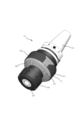
- FIG. 1 is a cross-sectional view of the tool holder unit 10 of the present invention
- FIG. 2 is an assembled disassembled perspective view showing a state in which the tool holder unit is divided
- FIG. 3 is a state immediately before the tool holder unit is connected. A cross section is shown.
- FIG. 4 is a perspective view showing a state in which the tool holder unit 10 of the present invention is connected and a collet and a nut are attached to the chuck portion.
- the split tool holder unit 10 has a chuck portion 11 for gripping a rotating tool such as a cutting tool with a collet 28 and a nut 29 (see FIG. 4 (positions of reference numerals 17 and 18 in FIG. 1)), and rotation of a machining center or the like.
- the shank portion 12 gripped by the spindle of the processing apparatus (not shown, but located above FIG. 1) is connected in the vertical direction.
- the chuck portion 11 has an annular brim portion 20 protruding around the outer circumference at an intermediate position in the vertical direction. Below the brim portion 20, the shank side connecting portion 19 extends with a diameter reduced from that of the brim portion 20.
- a chuck-side connecting portion 21 that has a diameter reduced from the brim portion 13 and tapers upward extends, and the inside thereof has a cylindrical concave space 14 with an open upper portion.
- the concave space 14 is a space in which an electronic substrate or the like, which will be described later, is inserted and fixed.
- the shank portion 12 and the chuck portion 11 of the tool holder unit 10 are inserted by nesting the tapered recess 16 of the shank side connecting portion 19 over the tapered portion 15 of the chuck side connecting portion 21 until the lower end 19a abuts on the brim portion 13. They are connected to each other by (press fitting).
- a nut 29 having a hollow space 17 having an upwardly reduced diameter for inserting the collet 28 for gripping the rotating tool inside the chuck portion 11 and tightening the collet 28 from the outside to fix the rotating tool is provided.
- the nut connecting portion 24 to be mounted extends, and a brim portion 13 is provided at the base of the upper portion thereof. ..
- the chuck portion 11 is provided with an antenna unit 50 and a charging unit 60, and charges the outer cover member 52 of the antenna unit 50 forming a part of the outer surface of the chuck portion 11.
- the unit 60 and the outer cover member 62 are attached to the brim portion 13 at the base of the nut connecting portion 24, and the annular cover 26 arranged on the outer periphery of the brim portion 20 of the shank portion 12 and the nut connecting portion 24 is used from above and below. It is sandwiched and fitted and fixed.
- the annular cover 26 is made of aluminum and is fastened to the screw hole 27a of the chuck portion 11 with a fixing screw 27.
- FIG. 5 is a perspective perspective view showing a state in which the electronic substrate unit 30 is mounted in the concave space 14 provided in the chuck side connecting portion 21 of the chuck portion 11.
- FIG. 7 is an enlarged cross-sectional view of the vicinity of the connecting portion between the chuck portion 11 and the shank portion 12 in a state where the electronic substrate unit 30 is mounted.
- the chuck portion 11 and the shank portion 12 are inserted into the shank side connecting portion 19 in a nested manner, and the tapered portion 15 on the outer peripheral surface of the chuck side connecting portion 21 is inserted into the shank side connecting portion 19. It is connected by press-fitting into the tapered recess 16 on the inner peripheral surface of 19.
- the concave space 14 of the chuck-side connecting portion 21 has an opening at the top and a cylindrical recess at the bottom, and the electronic substrate unit 30 is inserted and fixed in the concave space 14.
- FIG. 6 shows a perspective view of the board mounting base 31.
- the substrate mounting base 31 is a disk-shaped member having a thickness made of an insulating material such as resin, and is lowered from above along the inner diameter of the concave space 14 of the chuck portion 11 in the thickness direction, and the bottom portion 31a is recessed. It is placed on the bottom 14a of the space 14. At this time, an adhesive is applied to the bottom portion 31a (or the bottom portion 14a) and fixed. Further, an adhesive is applied to the side portion 31b of the substrate mounting base 31, and the inner wall 14b of the concave space 14 is sufficiently fixed.
- the side portion 31b is provided with a plurality of grooves in the circumferential direction to improve the adhesiveness and prevent the adhesive from leaking out.
- the upper surface of the substrate mounting base 31 is provided with a counterbore 31f recessed downward, and an edge portion 31h is provided along the outer circumference of the counterbore 31f.
- the counterbore 31 serves as a space for receiving electronic components of the lowermost electronic substrate 31, which will be described later.
- a through hole 31c for the temperature sensor unit is provided so that the temperature sensor unit 35 can protrude from below.
- a pair of notches 31d are provided on the side portion of the board mounting base 31 at positions symmetrical with each other by 180 °, and each of them provides a space through which the antenna cable and the charging cable described later pass.
- edge portion 31h is provided with four support bases 31i for spacers (described later) fixed on the bottom layer electronic substrate 31 that has entered the spot facing portion 31f and protrudes in the radial direction at 90 ° intervals.
- a screw hole 31e is formed in the center of the carrier 31i.
- the counterbore 31f is provided with eight pin receiving holes 31g so that the sockets and pins for electrical connection between the electronic boards 32 to 34 (described later) do not come into contact with the total length of the electronic board unit 30. Is shortened.
- a first electronic substrate 31 (also referred to as "lowermost electronic substrate 31") of an insulating material such as resin is laminated on the first electronic substrate 31.
- An electronic component is mounted on the lower surface side of the first electronic substrate 31, is received by the counterbore 31f, and is adhesively fixed to the edge portion 31h.
- the first electronic substrate 31 is also provided with a through hole 32e, a pin receiving hole 32e, and a notch 32d so as to look into the screw hole 31e, the pin receiving hole 31e, and the notch 31d of the carrier 31i.
- upper layer electronic substrate 33 and “upper layer electronic substrate 33 lower electronic substrate” are laminated.
- the second electronic substrate 33 and the third electronic substrate 34 (also referred to as “upper layer electronic substrate 34" and “upper electronic substrate 34 among the upper electronic substrates") of the insulating material such as resin are the first electronic substrate. They are laminated on the 32 in order and fixed by adhesion. At this time, also in the second electronic board 33 and the third electronic board 34, through holes of the second electronic board 33 and the third electronic board 34 so as to look through the screw holes 31e, the pin receiving holes 31e, and the notch 31d of the carrier base 31i. 33e and 34e, pin receiving holes 33e, and notches 33d and 34d are provided.
- notches 32d and 33d of the other electronic boards 32 to 33 four notches 34d of the third electronic substrate 34 are provided in an arc shape along the outer circumference. Regarding this point, the battery It will be described later in the description of the unit holder 42.
- spacers 36 having the same height are vertically arranged above the second electronic substrate 33 at positions looking through the through holes 33e, and the third electronic substrate 34 is laminated above the spacers 36.
- substrate fixing screws 37 are arranged through the through holes 34e of the third electronic substrate 34 through the spacers 36 to through holes 33e to 36 to 33e and screwed to the screw holes 31e of the substrate mounting base 31, respectively. .. Since the spacer 36 and the substrate fixing screw 37 are made of a metal material such as SUS and have conductivity, they play a role of making electrical connections between the electronic components of the electronic substrates 32 to 34, and the electronic substrates 32 to 34 and the electrons. It has the role of securing space between parts and preventing heat conduction. It should be added that the role of preventing heat conduction is larger in the thick substrate mounting base 31.
- power supply terminals 38 for supplying electric power to the electronic boards 32 to 34 and electronic components are arranged.
- the power supply terminal 38 employs a leaf spring type in order to apply a reaction force upward to fix the power supply terminal 38 so that the electrode 41a of the battery unit 41, which will be described later, abuts and is electrically connected.
- FIG. 8 to 9 show an assembled disassembled perspective showing a structure in which the battery unit 41 is connected and fixed to the power supply terminal 38 of the uppermost electronic board 34 in a state where the electronic board unit 30 is fixed in the concave space 14 of the chuck portion 11.
- 8 is a view from above
- FIG. 9 is a view from below.
- the battery unit 41 is provided with a frame member 41c on the outer periphery of the disk-shaped rechargeable battery 41a, and the electrode 41b is exposed from the lower portion of the frame member 41a.
- a protrusion 41d that protrudes outward in the radial direction is provided on the outer periphery of the frame member 41c.
- the battery unit 41 is received by the battery unit holder 42 from above.
- the battery unit holder 42 is made of an elastic material having an insulating property such as resin, and is provided with a counterbore 42a having an opening at the top and recessed downward, and the inner diameter of the counterbore 42a is outside the battery unit 41.
- the battery unit 41 is received in the spot facing 42a so as to approximate the diameter.
- a large through hole 42b is formed in the center of the spot facing 42a, and when the battery unit 41 is received, the electrode 41b of the battery 41a is exposed downward. Further, a recess 42d is provided on the inner wall around the counterbore 42a of the battery unit holder 42 on the outer side in the radial direction, and when the battery unit 41 is received, the protrusion 41d fits into the recess 42d and rotates in the rotational direction. Positioned.
- the bottom of the battery unit holder 42 is provided with an arc-shaped convex portion 42c that projects downward around the outer peripheral edge portion.
- the central angles of the arcs of the convex portions 42 are different from 43 °, 40 °, 48 °, and 40 °.
- the notch portion 34d of the third electronic substrate 34 on the uppermost layer also has an arc shape, and its central angles are adjusted to 43 °, 40 °, 48 °, and 40 °.
- the battery unit holder 42 not only protects the battery 41a, which is a rechargeable secondary battery and tends to be more vulnerable to vibration and shock than the primary battery, but also the convex portion 42c and the concave portion 42d form a third electron.
- the notch 34d of the substrate 34 and the protrusion 41d of the battery unit 41 By positioning the notch 34d of the substrate 34 and the protrusion 41d of the battery unit 41, the electrode 41b of the battery 41a and the corresponding leaf spring type power supply terminal 38 can be assembled without mistake.
- the counterbore 42a of the battery unit holder 42 is provided with four semi-through holes 42e at positions where the substrate fixing screw 37 of the electronic substrate unit 30 is viewed, and the electronic substrates 32 to 34 are provided via the substrate fixing screw 37. Prevents electrical interference with.
- the battery unit holding member 43 is placed on the battery unit holder 42.
- the battery unit holding member 43 is formed of a sponge material (insulating elastic member) such as urethane foam, and when the shank side connecting portion 19 of the shank portion 12 is placed over the chuck side connecting portion 21 of the chuck portion 11 to be connected.
- the battery unit 41 is pressed downward while being inserted and compressed between the top surface of the tapered recess 16 of the shank portion 12 and the battery unit 41. Therefore, due to the elastic force and the insulating property of the battery unit pressing member 43, the battery unit 41 is pressed against the electronic substrates 32 to 34 while being insulated from the shank portion 12 and the chuck portion 11 to protect the battery unit 41 from vibration and impact. It is fixed in the vertical direction (the electrical connection between the electrode 41b and the power supply terminal 38 is also maintained).
- the tool holder unit 10 has an antenna unit 50 mounted on its chuck portion 11.
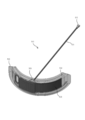
- 10 is a perspective view showing the configuration of the antenna unit 50 in an assembled state
- FIG. 11 is an exploded perspective view of the antenna unit showing a state in which the outer cover member is attached
- FIG. 12 is a tool in the vicinity of the antenna unit 50.
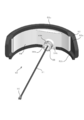
- a partially enlarged cross-sectional view of the holder 10 FIG. 13 is an assembled disassembled perspective view of each component of the antenna unit 50
- FIG. 14 is a perspective view of the antenna unit 50 of FIG. 10 as viewed from the inner cover member 54 side.
- the antenna unit 50 is generally composed of an outer cover member 52, a substrate antenna 53, an inner cover member 54, an antenna cable 51, and a connector 55 in this order from the outside.
- the substrate antenna 53 is flexible (flexible) so that it can be arranged on the outermost circumference of the tool holder unit 10 in consideration of radio wave interference, noise generation, transmission capacity, etc. in the tool holder unit 10 which has a large environmental load and rotates at high speed.
- a plate-shaped antenna is used.
- the inner cover member 54 and the substrate antenna 53 are substantially arc-shaped members, and are formed with a curvature that can be attached to each other and conform to the outer cover member 52 described later.
- the inner cover member 54 is a resin material member that is injection-molded, and as shown in FIG.
- the entire back surface of the substrate antenna 53 is received and adhered to the surface on the outer cover member side (diameterally outside of the tool holder unit 10).
- a recess 54a is provided so that the recess 54a can be formed.
- a substantially cylindrical fitting boss 56 projects from the back surface of the inner cover member 54. As shown in FIGS. 14 and 12, the fitting boss 56 has a through hole 56a that penetrates the inner cover member 54 at the center thereof, and an annular groove 56b is provided on the outer peripheral wall. Has been done.
- the antenna cable 51 is inserted into the annular groove 56b and mounted on the back surface of the substrate antenna 53.
- the antenna cable 51 is attached to the back surface of the substrate antenna 53 by bending the tip of the antenna cable 51 at a gap between the back surface of the substrate antenna 53 and the recess 54a of the inner cover member 54. Then, an adhesive is filled inside the through hole 56a of the fitting boss 56, and the antenna cable 51 is fixed so as not to move by centrifugal force.
- the outer cover member 52 has an arc shape whose surface forms the outer surface of the chuck portion 11, and is made of an injection-moldable radio wave transmitting material such as resin.
- the back surface of the outer cover member 52 has a receiving surface 52a that abuts the entire surface of the inner cover member 54 on which the substrate antenna 53 is mounted on the edge portions 52c that are vertically arranged in an arc shape, and the inner cover 52a has an inner cover. The surfaces of the member 54 and the substrate antenna 53 are brought into contact with each other and fitted to the outer cover member 52 in the vertical direction.
- the adhesive is continuously applied to the edge of the surface of the inner cover member 54 in a frame shape to prevent the intrusion of cutting oil and the like and fix the adhesive.
- a thick portion 53a is formed on the outer cover member side, and a recess 52b is provided at a corresponding position of the outer cover member 52.
- the recess 52b is a portion that receives the thickness of the thick portion 53a of the substrate antenna 53 and the tip of the antenna cable 51 that is bent and mounted on the back surface of the substrate antenna 53.
- the inner cover member 54 has a protrusion 54b protruding upward along the upper edge portion thereof.
- the upper edge portion 52c of the outer cover member 52 has a notch portion 52d at a corresponding position.
- the outer cover member 52 and the inner cover member 54 are each made by injection molding, but both are formed in an arc shape of less than 180 °. This is because it is necessary to provide a so-called draft when extracting from the injection molding mold. This point is the same for the charging cover unit 60, and the existence of the key 70 and the positioning in the rotation direction due to the fact that the antenna unit 50 and the charging unit 60 cannot form 360 ° will be described later.
- the fitting boss 56 of the inner cover member 54 is inserted into the antenna hole 57 (see also FIG. 5) through which the concave space 14 of the chuck portion 11 communicates with the outside.
- An annular groove 56b is formed on the outer periphery of the fitting boss 56, and the fitting boss 56 is inserted into the antenna hole 57 with a packing such as an O-ring (not shown) attached to the annular groove 56b. It prevents cutting oil and the like from entering the concave space 14.
- the tool holder unit 10 has a charging unit 60 mounted on its chuck portion 11.
- 15 is an assembled and disassembled perspective view of each part of the antenna unit 50
- FIG. 16 is a perspective view showing the configuration of the assembled charging unit 60
- FIG. 17 is a tool holder unit 10 showing the vicinity of the charging unit 60. A partially enlarged cross-sectional view is shown.
- the charging unit 60 is generally composed of an outer cover member 62, a charging terminal board 63, an inner cover member 64, a charging cable 61, and a connector 65 in this order from the outside.
- the charging terminal board 63 fixes a terminal for supplying electric power from an external power source to the battery unit 41 (battery 41a) described above via a charging cable (electric cable) 61.
- the inner cover member 64 and the outer cover member 62 are substantially arc-shaped members, and are resin material members that are injection-molded with the same curvature as the inner cover member 54 and the outer cover member 52 of the antenna unit 50, respectively. As shown in FIG.
- the charging terminal board 63 is attached to the outer cover member 62 by a charging terminal 68 that fits and accepts the entire surface of the charging terminal board 63 on the back surface thereof and also serves as a fixing screw.
- a recess 62b is provided.
- Three through holes 63a and 62d are formed in the charging terminal substrate 63 and the recess 62b of the outer cover member 62 at positions where they can look into each other, and the charging terminal substrate 63 is passed through the through holes 63a and 62d. It is fixed to the recess 62b. At this time, the tip of the charging terminal 68 is exposed to the outside through the through hole 62d, and an external power plug is connected there. In this example, charging with a 3P power plug is assumed.
- a substantially cylindrical fitting boss 66 protrudes from the back surface of the inner cover member 64.
- the fitting boss 66 has a through hole 66a penetrating the inner cover member 64 at the center thereof, similarly to the fitting boss 56 (see FIG. 14) of the antenna unit 50 described above, and has an outer circumference.
- An annular groove 66b is provided on the wall.
- the charging cable 61 is inserted into the annular groove 66b and mounted on the back surface of the charging terminal board 6. To attach the charging cable 61 to the back surface of the charging terminal board 63, insert the tip of the charging cable 61 between the head 68a of the charging terminal 68 and the charging terminal board 63 when inserting and fixing the charging terminal 68 into the through hole 63a.
- the inner cover member 62 is attached to the outer cover member 62 in a state where the charging terminal board 63 and the charging cable 61 are fixed to the outer cover member 62.
- the outer cover member 62 has an arc shape whose surface forms the outer surface of the chuck portion 11, and is made of an injection-moldable material such as resin.
- the back surface of the outer cover member 62 has a receiving surface 62a for abutting and adhering the entire surface of the inner cover member 64 in a state where the charging terminal substrate antenna 63 is fixed to the frame-shaped edge portion 62c surrounding the periphery.
- the inner cover member 64 is fixed to the outer cover member 62.
- the fitting boss 66 of the inner cover member 64 is inserted into the charging cable hole 67 (see also FIG. 5) through which the concave space 14 of the chuck portion 11 communicates with the outside.
- An annular groove 66b is formed on the outer periphery of the fitting boss 66, and the fitting boss 66 is inserted into the charging cable hole 67 with a packing such as an O-ring (not shown) attached to the annular groove 66b. , Prevents cutting oil and the like from entering the concave space 14.
- FIG. 18 shows a perspective view of a state in which the antenna unit 50 and the charging unit 60 are attached to the chuck portion 11.
- the antenna unit 50 and the charging unit 60 are mounted by sandwiching the brim portion 13 of the chuck portion 11 between the edge portions 52c and 62c of the outer cover members 52 and 62.
- the outer cover member 62 and the inner cover member 64 are formed in an arc shape of less than 180 ° for convenience of injection molding, and the antenna unit 50 and the charging unit 60 cannot form 360 ° around the outer circumference.
- the small cover member 70 made of aluminum alloy is adopted in consideration of strength, lightness, workability and decorativeness.
- connecting shaft members 21a are arranged on the upper surface of the brim portion 13 of the chuck portion 11.
- the chuck portion 11 is connected to the shank portion 12 by inserting the connecting shaft member 21a into the connecting hole 19c (see FIG. 2) formed in the lower end 19a of the shank connecting portion 19 of the shank portion 12.
- a substantially annular key 71 is fitted and inserted into a pair of connecting shaft members 21a arranged at positions rotated by approximately 90 ° from the antenna hole 57 and the charging cable hole 67 of the connecting shaft member 21a.
- Each of the keys 71 is provided with a protrusion 71a that projects outward in the radial direction.
- the small cover member 70 is provided with a fitting recess 70a on the inner side surface in the radial direction, and the protrusion 71a of each key 71 is fitted and positioned in the fitting recess 70a. Therefore, when the small cover member 70 is assembled between the outer cover members 52 and 62, the positioning of the outer cover members 52 and 62 in the rotation direction can be achieved by the small cover member 70, and fatigue due to repeated deceleration and acceleration during high-speed rotation can be achieved. The small cover member 70 can catch it, and fatigue failure of the resin outer cover members 52 and 62 can be prevented.
- the corresponding connection hole 19b of the shank side connecting portion 19 is provided with a recess 19C so as to have a height different from the others.
- the annular cover 26 is inserted around the nut connecting portion 24 from below with the outer cover members 52, 62 and the small cover member 70 assembled to the chuck portion 11.
- Four through holes 26a and connecting holes 13a are bored at positions where the annular cover 26 and the brim portion 13 look into each other at substantially the same intervals in the rotational direction, and the through holes are formed when the annular cover 26 is attached to the brim portion 13.
- the fixing screw 27 is inserted into the connecting hole 13a at 26a and fixed. Further, as shown in FIGS.
- the outer peripheral edge portion 19d of the brim portion 19 of the chuck portion 11 protrudes downward (hangs down), and the outer peripheral edge portion 26b of the annular 26 protrudes upward (stands up). There is. Therefore, when the chuck portion 11 and the annular cover 26 are connected to the shank portion 12, the outer peripheral edges 19d and 26b fit into the upper and lower edge portions 52c and 62c of the outer cover members 52 and 62 (and the small cover member 70). In addition, it prevents fixing and loosening in the vertical direction.
- FIG. 1 shows a cross-sectional view of the tool holder unit 10 in which the collet 28, the nut 29, and the rotary tool 72 are omitted, but FIG. 19 shows the collet 28, the nut 29, and the rotary tool 72 (hereinafter, also referred to as “rotary tool 72”).
- FIG. 19 shows the collet 28, the nut 29, and the rotary tool 72 (hereinafter, also referred to as “rotary tool 72”).
- a cross-sectional view of the tool holder unit 10 provided with (referred to as) is shown.
- FIG. 19 is mainly referred to.
- 20A and 20B are vertical cross-sectional views of the temperature sensor unit 35, where FIG. 20A shows a state when uncompressed and FIG. 20B shows a state when compressed.
- FIG. 21A and 21B show the vicinity of the movable substrate 35c in the tubular main body 35b of the temperature sensor unit 35, where FIG. 21A is a partially transparent perspective view and FIG. 21B is a partial cross-sectional view.
- FIG. 22 shows an assembled disassembled perspective view of the temperature sensor unit 35 and the tool holder unit 10 in the state where the collet 28, the nut 29, and the rotating tool 72 are not provided in (a), as viewed from below (b) and (c). ) Show transparent perspective views of the temperature sensor unit 35 viewed from diagonally above and diagonally below, respectively.
- FIG. 23 is a partial cross-sectional view of the tool holder unit 10 in the vicinity of the temperature sensor unit 35, and for convenience of explanation, the internal structure of the temperature sensor unit 35 is a perspective view.
- the temperature sensor unit 35 is electrically connected to a substantially hollow tubular main body 25b, a flange 35a forming an annular flange at the base thereof, and one end of the movable substrate 35c inside the tubular main body 25b.
- a thermocouple 75 (covered with a sheath 73) whose other end is inserted and fixed at a temperature measurement point in the rotary tool 72, a screw portion 35d that protrudes downward from the flange portion 35a and has a through hole inside, and a tubular main body portion.
- a terminal board 35e that is abutted and fixed to the top surface (upper surface) of 25b and electrically connected to the movable board 35c, a pin member 35f as a guide element that brings the movable member 35c closer to and separated from the terminal board 35d, and a pin member 35f. It is composed of a coil spring 35g which is arranged around the above and generates a reaction force while electrically connecting the movable substrate 35c and the terminal substrate 35e.
- the tip of the thermocouple 75 extending from the temperature measurement point inside the rotary tool 72 held by the collet 28 arranged inside the nut connecting portion 24 is an electronic substrate (this). In the example, it is connected to the electronic component of the second electronic board 33), but the temperature sensor unit 35 is used to connect the thermocouple 75 and the second electronic board 33.
- through holes 14c, 31c, 32e for the temperature sensor unit are located at the centers of the bottom portion 14a of the concave space 14 of the chuck portion 11 on which the electronic substrate unit 30 is placed and fixed, the substrate mounting base 31, and the first electronic substrate 32e, respectively.
- the above-mentioned through hole 32e) is drilled, and the tubular main body 35b of the temperature sensor unit 35 is inserted from below the inside of the nut connecting portion 24, and the upper end is a concave space through the through holes 14c, 31c, 32e for the temperature sensor unit. It projects to the vicinity of the lower surface of the second electronic substrate 33 in 14.
- the flange portion 35a at the base of the tubular main body portion 35b serves as an upward stopper and comes into contact with the bottom portion 14a of the concave space 14.
- the inside of the tubular main body 35b has a cylindrical space, and the upper surface is formed as a lid member that closes the upper part of the internal space, and has a disk shape that serves as an electrical contact with the second electronic substrate 33.
- Terminal board 35e is mounted. As shown in FIG. 22B, the terminal board 35e has a conductive portion 35h, which is an electrical contact, formed in a ring shape concentric with the center of the shaft. As a result, the temperature sensor unit 35 can be electrically connected to the second electronic substrate 33 at any angle.
- the internal space of the tubular main body 35b is vertically connected by a pin member 35f from the bottom thereof to the terminal board 35. As shown in FIG.
- a movable substrate 35c is slidably mounted on the pin member 35f along the pin member 35f, and a metal or the like is conductive around the pin member 35f between the movable substrate 35c and the terminal substrate 35e.
- a coil spring 35 g of the material is arranged. Therefore, when a force for pushing up the movable substrate 35e from below is applied, the coil spring 35g is compressed (see FIG. 20B), and when the force for pushing up is eliminated (or a force for pushing up) is applied, the coil spring 35g is extended to the movable member 35e. It moves and returns to its original position (or moves to a lower position (see FIG. 20A)).
- the vertical movement of the movable substrate 35c is performed by following the invasion of the pipe member 74.
- the pipe member 74 is a tubular member, the tip of which is inserted and fixed from below the movable substrate 35c and protrudes upward, and the lower end of the pipe member 74 passes through a through hole in the screw portion 35d and is inserted into the rotary tool 72. It is fixed. Therefore, when the pipe member 74 connected to the rotary tool 72 is pushed upward, the movable substrate 35c interlocking with the pipe member 74 is pushed up along the pin member 35f while resisting the repulsive force of the coil spring 35g, and conversely, the pipe member 74. Is pulled down, the movable substrate 35c is pulled down along the pin member 35f.
- thermocouple 75 (including a wire thereof) is inserted inside the pipe member 74 over the entire longitudinal direction, and both ends of the thermocouple 75 protrude from the pipe member 74.
- the upper end of the thermocouple 75 protrudes from the pipe member 74 protruding from the movable substrate 35c, and the upper end thereof is attached to the conductive portion 35j (thin film or the like) of the movable substrate 35c by the connecting wire 35i. It is electrically connected.
- the conductive portion 35j is electrically connected to the lower end of the coil spring 35g, and the upper end of the coil spring 35g is connected to the conductive portion 35h of the terminal board 35e.
- thermocouple 75 the sheath 73, and the pipe member 74 are seated with the chuck portion 11.
- the conductive portion 35h of the terminal board 35e is formed of a central circle and its concentric ring, and the conductive portion 35h is electrically connected to a connection terminal arranged on the lower surface of the third electronic board 33.
- FIG. 24 shows a schematic cross-sectional view of the tool holder unit 10 when a flow path for cooling oil (hereinafter, also referred to as “coolant”) is provided inside.
- the tool holder unit 10 has a structure in which coolant is discharged from the tip (lower end) of the rotary tool 72 through the internal flow paths of the shank portion 12, the chuck portion 11, and the rotary tool 71 from the spindle of the machining apparatus (arrow A). -See arrow F). First, the coolant flows into the main flow path 80 connected to the coolant flow path (not shown) of the main shaft (see arrow A).
- the main flow path 80 is bored downward from the upper end of the shank portion 12 along the rotation axis.
- the coolant that has passed through the main flow path 80 flows into a plurality of first flow paths 81 that extend radially from the main flow path 80 in the outer peripheral direction (see arrow B).
- the first flow path 81 is created by drilling from the outside to the inside in the radial direction to the main flow path 80, and is sealed from the outside by a set screw 85.
- the second flow path 82 is formed by bending downward on the radial outer side of each first flow path 81, and extends downward from the inside of the wall thickness of the shank-side connecting portion 19 of the shank portion 12 to the bottom portion 19a thereof. As shown in FIG. 2, the second flow path 82 is created by drilling the inside of the wall thickness from the bottom 19a side of the shank side connecting portion 19 to the first flow path 81.
- the outlet 82a of the second flow path 82 forms a spot facing around it, and an O-ring 82b having a thickness that protrudes to the outside when mounted on the spot facing is mounted.
- the coolant that has flowed through the second flow path 82 flows into the third flow path 83 that is fluidly connected to the second flow path 82.
- the third flow path 83 extends downward in the thickness direction inside the brim portion 13 of the chuck portion 11, and is connected to the fourth flow path 84 below the brim portion 13.
- the fourth flow path 84 is bent inward in the radial direction at the lower end of the third flow path 83, and extends in four radial directions toward the center (see arrow D).
- the fourth flow path 84 is perforated from the outside to the inside in the radial direction, and is sealed from the outside with a set screw 86.
- the third flow path 83 is created by drilling from above the brim portion 13 to the fourth flow path 84 in a state where the fourth flow path 84 is perforated. Then, the coolant that has flowed to the fourth flow path 84 flows into the space 88 below the plate nut (see FIG. 22A) that supports the flange portion 35a of the temperature sensor unit 35, and spirals in the rotary tool 71. It flows into the shaped flow path 72b (see arrow E) and is discharged from the lower end of the rotary tool 72 (see arrow F).
- An annular O-ring 87 is inserted between the flange portion 35a of the temperature sensor unit 35 and the bottom portion 14a of the concave space 14. The O-ring 87 is fixed on a flat surface in consideration of workability at the time of mounting and reduction of the total length of the tool holder unit 10.
- the partial cross-sectional view of FIG. 25 shows a structure for preventing coolant from entering the temperature sensor unit 35.
- the thermocouple 75 (and the sheath 73, the pipe member 74) is slidably inserted into the through hole 35 m inside the screw portion 35d, and the upper end thereof is inside the tubular main body portion 35b. It is projected to. Therefore, it is necessary to prevent the coolant from entering the inside of the tubular main body 35b through the through hole 35m of the screw 35d.
- an annular O-ring 80, a washer 81, and an O-ring 82 through which the pipe member 74 is passed are arranged in the through hole 35 m. By sandwiching the metal washer 81 between the resin O-rings 80 and 82, it is possible to prevent the pipe member 74 from sliding up and down, deforming the O-ring within the through hole 35 m, and reducing the sealing effect. There is.
- this tool holder unit also has a set screw 96 that plays a role of weight adjustment.
- the tool holder unit 10 rotates at a high speed, and if the weight balance in the radial direction is unbalanced, extra vibration and stress are generated, which leads to a decrease in accuracy as a measuring device.
- a set screw 96 is used as an adjusting element for weight balance. As an example, FIG.
- FIG. 26 shows a schematic cross-sectional view in which the shank portion 12 is cut in the horizontal direction at the height of the set screw 96 (see reference numeral 96 in FIG. 2).
- a screw hole 95 into which a set screw 96 can be inserted / fastened is drilled on the outer periphery of the shank portion 12.
- four screw holes 95 are provided at 90 ° intervals. This is to adjust the weight balance in the XY directions.
- FIG. 26A shows an example in which the weight in the XY direction is unbalanced in the state where the set screw is not inserted (left figure), and the set screws 96a to 96d made of steel having different lengths are used.
- ⁇ M5, density 7.9 g / cm2) is inserted into the screw holes 96a to 96d to adjust the weight balance in the XY directions (right figure).
- FIG. 26B the same steel retaining screws 96a to 96c as in FIG. 26A having different lengths were inserted into the screw holes 96a to 96c, and the weight balance could be adjusted in the Y direction.
- Recessed portion 52c ... Edge portion 52d ... Notch 53 ... Board antenna 53a ... Thick part 54 ... Inner cover member 54a ... Recessed 54b ... Protrusion 55 ... Connector 56 ... Fitting boss 56a ... Through hole 56b ... Circular groove 57 ... Antenna hole 60 ... Charging unit 61 ... Charging cable 62 ... Outer cover member 62a ... Receiving surface 62b ... Recessed portion 62c ... Edge 62d ... Through hole 63 ... Charging terminal board 63a ... Through hole 64 ... Inner cover member 65 ... Connector 66 ... Fitting boss (boss) 66a ... Through hole 66b ... Circular groove 67 ...
- Charging cable hole 68 Charging terminal 68a ... Head 70 ... Small cover member 70a ... Fitting recess 71 ... Key (key member) 71a ... Protrusion 72 ... Rotating tool (rotating tool) 72a ... Through hole (semi-through hole) 72b ... Flow path (fourth flow path) 73 ... Sheath 74 ... Pipe member (tubular member) 75 ... Thermocouple (including its wire) 76 ... Plate nut 80 ... Main flow path 81 ... First flow path 82 ... Second flow path 82a ... Outlet 82b ... O-ring 83 ... Third flow path 84 ... Fourth flow path 85 ... Fastening screw 86 ...
Landscapes
- Physics & Mathematics (AREA)
- General Physics & Mathematics (AREA)
- Engineering & Computer Science (AREA)
- Mechanical Engineering (AREA)
- Arrangements For Transmission Of Measured Signals (AREA)
Priority Applications (1)
| Application Number | Priority Date | Filing Date | Title |
|---|---|---|---|
| JP2021540942A JP7639245B2 (ja) | 2019-08-19 | 2020-08-17 | ツールホルダユニット |
Applications Claiming Priority (2)
| Application Number | Priority Date | Filing Date | Title |
|---|---|---|---|
| JP2019150035 | 2019-08-19 | ||
| JP2019-150035 | 2019-08-19 |
Publications (1)
| Publication Number | Publication Date |
|---|---|
| WO2021033671A1 true WO2021033671A1 (ja) | 2021-02-25 |
Family
ID=74661138
Family Applications (1)
| Application Number | Title | Priority Date | Filing Date |
|---|---|---|---|
| PCT/JP2020/031027 Ceased WO2021033671A1 (ja) | 2019-08-19 | 2020-08-17 | ツールホルダユニット |
Country Status (2)
| Country | Link |
|---|---|
| JP (1) | JP7639245B2 (https=) |
| WO (1) | WO2021033671A1 (https=) |
Citations (9)
| Publication number | Priority date | Publication date | Assignee | Title |
|---|---|---|---|---|
| JPS61109664U (https=) * | 1984-12-21 | 1986-07-11 | ||
| JPH03109707U (https=) * | 1990-02-28 | 1991-11-11 | ||
| JPH0555015U (ja) * | 1991-12-26 | 1993-07-23 | 三菱電線工業株式会社 | 接触プローブ装置 |
| JPH08108317A (ja) * | 1994-10-12 | 1996-04-30 | Kato Koki Kk | タップホルダー |
| WO1998035781A1 (en) * | 1997-02-14 | 1998-08-20 | Nt Engineering Kabushiki Kaisha | Working machine and its communication method |
| JPH11254210A (ja) * | 1998-03-12 | 1999-09-21 | Nt Engineering Kk | 道具位置調整構造および作業機械 |
| JP2003071676A (ja) * | 2001-08-31 | 2003-03-12 | Nippei Toyama Corp | 主軸の回転バランス調節構造 |
| WO2015022967A1 (ja) * | 2013-08-13 | 2015-02-19 | 株式会社山本金属製作所 | 温度測定方法、及び、温度測定装置 |
| JP2018054611A (ja) * | 2016-09-27 | 2018-04-05 | 株式会社山本金属製作所 | 振動測定装置 |
Family Cites Families (7)
| Publication number | Priority date | Publication date | Assignee | Title |
|---|---|---|---|---|
| JP6480274B2 (ja) * | 2015-06-22 | 2019-03-06 | 日立Geニュークリア・エナジー株式会社 | 回転工具、加工状態監視装置および工作機械 |
| US20180178293A1 (en) * | 2015-06-27 | 2018-06-28 | Yamamoto Metal Technos Co., Ltd. | Rotary machine tool equipped with sensor for real-time detection of state |
| JP7233068B2 (ja) * | 2016-09-09 | 2023-03-06 | 株式会社NejiLaw | ブレーキパッド |
| JP2018051760A (ja) * | 2016-09-27 | 2018-04-05 | 株式会社山本金属製作所 | 手持ち式工具に用いる無線式測定ユニット |
| JP7049978B2 (ja) * | 2018-12-03 | 2022-04-07 | 株式会社日立製作所 | 切削加工システム、加工誤差測定方法、および加工誤差測定装置 |
| JP2020104237A (ja) * | 2018-12-28 | 2020-07-09 | 株式会社山本金属製作所 | リアルタイム振動測定ユニット |
| WO2020149316A1 (ja) * | 2019-01-15 | 2020-07-23 | 株式会社山本金属製作所 | 工作機械の外部処理システム |
-
2020
- 2020-08-17 WO PCT/JP2020/031027 patent/WO2021033671A1/ja not_active Ceased
- 2020-08-17 JP JP2021540942A patent/JP7639245B2/ja active Active
Patent Citations (9)
| Publication number | Priority date | Publication date | Assignee | Title |
|---|---|---|---|---|
| JPS61109664U (https=) * | 1984-12-21 | 1986-07-11 | ||
| JPH03109707U (https=) * | 1990-02-28 | 1991-11-11 | ||
| JPH0555015U (ja) * | 1991-12-26 | 1993-07-23 | 三菱電線工業株式会社 | 接触プローブ装置 |
| JPH08108317A (ja) * | 1994-10-12 | 1996-04-30 | Kato Koki Kk | タップホルダー |
| WO1998035781A1 (en) * | 1997-02-14 | 1998-08-20 | Nt Engineering Kabushiki Kaisha | Working machine and its communication method |
| JPH11254210A (ja) * | 1998-03-12 | 1999-09-21 | Nt Engineering Kk | 道具位置調整構造および作業機械 |
| JP2003071676A (ja) * | 2001-08-31 | 2003-03-12 | Nippei Toyama Corp | 主軸の回転バランス調節構造 |
| WO2015022967A1 (ja) * | 2013-08-13 | 2015-02-19 | 株式会社山本金属製作所 | 温度測定方法、及び、温度測定装置 |
| JP2018054611A (ja) * | 2016-09-27 | 2018-04-05 | 株式会社山本金属製作所 | 振動測定装置 |
Also Published As
| Publication number | Publication date |
|---|---|
| JP7639245B2 (ja) | 2025-03-05 |
| JPWO2021033671A1 (https=) | 2021-02-25 |
Similar Documents
| Publication | Publication Date | Title |
|---|---|---|
| JP7621582B2 (ja) | 分割式ツールホルダユニット | |
| JP7198340B2 (ja) | ホルダ、切削工具、切削加工物の製造方法及びデータの収集方法 | |
| WO2017002762A1 (ja) | リアルタイム状況検知用のセンサ付き回転加工工具 | |
| US11162973B2 (en) | Three-axis piezoelectric accelerometer | |
| US11965794B2 (en) | System for wireless and passive monitoring of strain during manufacturing processes | |
| US20180301773A1 (en) | Battery pack | |
| US8791612B2 (en) | Electric motor having air purge function | |
| CN108136511A (zh) | 具有集成的传感装置的刀架 | |
| JP2015189000A (ja) | 締付チャック | |
| US20230116863A1 (en) | Tool holder for tool assembly and tool assembly comprising tool holder | |
| US10478934B2 (en) | Instrumented tool post, and associated tool holder | |
| WO2021033671A1 (ja) | ツールホルダユニット | |
| JPWO2020213712A1 (ja) | 旋削工具本体、旋削工具及びデータ収集システム | |
| US12330221B2 (en) | Tool holder with measuring apparatus | |
| CN109798933B (zh) | 无线仪器 | |
| WO2022123740A1 (ja) | 切削工具 | |
| JP7120489B1 (ja) | 切削工具および切削装置 | |
| CN210775337U (zh) | 一种可调频超声波探头 | |
| KR102720077B1 (ko) | 압전 변환기 | |
| EP3012610B1 (en) | Systems and methods for mounting the printed wiring assembly to the header assembly of a pressure sensor | |
| US12320204B1 (en) | Interconnectable downhole instrument package | |
| JP7537656B1 (ja) | 転削工具 | |
| JP2019034380A (ja) | トルク測定装置 | |
| CN113395649A (zh) | 测试机构 | |
| WO2025182084A1 (ja) | センサモジュールおよびシステム |
Legal Events
| Date | Code | Title | Description |
|---|---|---|---|
| 121 | Ep: the epo has been informed by wipo that ep was designated in this application |
Ref document number: 20854220 Country of ref document: EP Kind code of ref document: A1 |
|
| ENP | Entry into the national phase |
Ref document number: 2021540942 Country of ref document: JP Kind code of ref document: A |
|
| NENP | Non-entry into the national phase |
Ref country code: DE |
|
| 122 | Ep: pct application non-entry in european phase |
Ref document number: 20854220 Country of ref document: EP Kind code of ref document: A1 |