WO2021033671A1 - Tool holder unit - Google Patents
Tool holder unit Download PDFInfo
- Publication number
- WO2021033671A1 WO2021033671A1 PCT/JP2020/031027 JP2020031027W WO2021033671A1 WO 2021033671 A1 WO2021033671 A1 WO 2021033671A1 JP 2020031027 W JP2020031027 W JP 2020031027W WO 2021033671 A1 WO2021033671 A1 WO 2021033671A1
- Authority
- WO
- WIPO (PCT)
- Prior art keywords
- cover member
- unit
- tool holder
- hole
- antenna
- Prior art date
Links
Images


Classifications
-
- B—PERFORMING OPERATIONS; TRANSPORTING
- B23—MACHINE TOOLS; METAL-WORKING NOT OTHERWISE PROVIDED FOR
- B23Q—DETAILS, COMPONENTS, OR ACCESSORIES FOR MACHINE TOOLS, e.g. ARRANGEMENTS FOR COPYING OR CONTROLLING; MACHINE TOOLS IN GENERAL CHARACTERISED BY THE CONSTRUCTION OF PARTICULAR DETAILS OR COMPONENTS; COMBINATIONS OR ASSOCIATIONS OF METAL-WORKING MACHINES, NOT DIRECTED TO A PARTICULAR RESULT
- B23Q17/00—Arrangements for observing, indicating or measuring on machine tools
- B23Q17/09—Arrangements for observing, indicating or measuring on machine tools for indicating or measuring cutting pressure or for determining cutting-tool condition, e.g. cutting ability, load on tool
-
- B—PERFORMING OPERATIONS; TRANSPORTING
- B23—MACHINE TOOLS; METAL-WORKING NOT OTHERWISE PROVIDED FOR
- B23Q—DETAILS, COMPONENTS, OR ACCESSORIES FOR MACHINE TOOLS, e.g. ARRANGEMENTS FOR COPYING OR CONTROLLING; MACHINE TOOLS IN GENERAL CHARACTERISED BY THE CONSTRUCTION OF PARTICULAR DETAILS OR COMPONENTS; COMBINATIONS OR ASSOCIATIONS OF METAL-WORKING MACHINES, NOT DIRECTED TO A PARTICULAR RESULT
- B23Q3/00—Devices holding, supporting, or positioning work or tools, of a kind normally removable from the machine
- B23Q3/12—Devices holding, supporting, or positioning work or tools, of a kind normally removable from the machine for securing to a spindle in general
-
- B—PERFORMING OPERATIONS; TRANSPORTING
- B23—MACHINE TOOLS; METAL-WORKING NOT OTHERWISE PROVIDED FOR
- B23Q—DETAILS, COMPONENTS, OR ACCESSORIES FOR MACHINE TOOLS, e.g. ARRANGEMENTS FOR COPYING OR CONTROLLING; MACHINE TOOLS IN GENERAL CHARACTERISED BY THE CONSTRUCTION OF PARTICULAR DETAILS OR COMPONENTS; COMBINATIONS OR ASSOCIATIONS OF METAL-WORKING MACHINES, NOT DIRECTED TO A PARTICULAR RESULT
- B23Q5/00—Driving or feeding mechanisms; Control arrangements therefor
- B23Q5/02—Driving main working members
- B23Q5/04—Driving main working members rotary shafts, e.g. working-spindles
-
- G—PHYSICS
- G01—MEASURING; TESTING
- G01H—MEASUREMENT OF MECHANICAL VIBRATIONS OR ULTRASONIC, SONIC OR INFRASONIC WAVES
- G01H17/00—Measuring mechanical vibrations or ultrasonic, sonic or infrasonic waves, not provided for in the preceding groups
-
- G—PHYSICS
- G01—MEASURING; TESTING
- G01K—MEASURING TEMPERATURE; MEASURING QUANTITY OF HEAT; THERMALLY-SENSITIVE ELEMENTS NOT OTHERWISE PROVIDED FOR
- G01K1/00—Details of thermometers not specially adapted for particular types of thermometer
- G01K1/02—Means for indicating or recording specially adapted for thermometers
- G01K1/024—Means for indicating or recording specially adapted for thermometers for remote indication
-
- G—PHYSICS
- G01—MEASURING; TESTING
- G01K—MEASURING TEMPERATURE; MEASURING QUANTITY OF HEAT; THERMALLY-SENSITIVE ELEMENTS NOT OTHERWISE PROVIDED FOR
- G01K1/00—Details of thermometers not specially adapted for particular types of thermometer
- G01K1/14—Supports; Fastening devices; Arrangements for mounting thermometers in particular locations
Definitions
- the present invention relates to a structure of a substantially tubular tool holder unit that detects the temperature and / or vibration of a rotating tool of a rotating processing device such as a cutting device in real time.
- Patent Document 1 a tool holder unit capable of measuring the temperature during machining of a rotating tool (hereinafter, also referred to as "rotating tool"), and has also developed and provided an abnormality prediction technology based on this measurement result.
- rotating tool a rotating tool
- Patent Document 2 It is also known that vibration and stress other than temperature are important factors such as tool breakage.
- Patent Document 3 Refer to Patent Document 1 etc.).
- the electronic board and rechargeable battery are mounted inside the tool holder that rotates at high speed, and in order to improve the accuracy as a measuring device, a large centrifugal force or output from the electronic board to external and external parts is required. It was necessary to consider the problems of noise generation due to deterioration / attenuation of radio waves and interference. Further, it is desirable that the electronic component for processing the measurement data mounted inside the tool holder, the antenna for wireless transmission connected to the charging battery, and the charging device for the battery are mounted externally for convenience of access.
- the outside of the tool holder unit is exposed to high-temperature, high-pressure, high-speed cutting oil, chips, cooling water, etc., and it is necessary to protect the power supply terminals for wireless communication equipment and charging batteries, and the internal electronic board. There is. It also needs to have a fixing force that can withstand a large centrifugal force.
- wireless communication devices are required to sufficiently emit radio waves to the outside in such a harsh environment.
- the structure is originally such that cutting fluid or the like easily enters from the outside at the connecting position of the split parts, and even if the split type has a sufficient waterproof / drip-proof effect. , It is necessary to have a centrifugal force resistant structure. Furthermore, when the data from the thermocouple in the rotating tool is received and processed by the electronic component mounted on the electronic board in the tool holder unit, the harmful effect of connecting the wire of the thermocouple directly to the internal electronic board. Is also considered.
- the present invention was created in view of such circumstances, and is a tool holder unit that is attached to the spindle of a rotary processing apparatus and can measure the temperature, vibration, etc. of a rotary tool in real time, and wirelessly transmits with high accuracy during high-speed rotation. It is an object of the present invention to provide a suitable structure of a tool holder unit which can measure the temperature while preventing the intrusion of cutting oil and the like from the outside and is easy to charge and assemble.
- Antenna unit Specifically, the present invention A substantially tubular tool holder unit that detects temperature information and / or vibration information of a rotating tool being machined by a rotary processing device in real time and wirelessly transmits it to the outside.
- the tool holder unit grips the rotary tool on the lower chuck portion side and is gripped on the spindle of the rotary processing device on the upper shank portion side, and is mounted in the internal space to provide at least temperature information of the rotary tool.
- An electronic board unit that receives and / or receives and transmits vibration information, and an antenna unit that receives the temperature information and / or vibration information from the electronic board unit via an antenna cable and wirelessly transmits the vibration information to the outside.
- the antenna unit is mounted on the outer periphery of the tool holder unit with the inside sealed from the outside.
- this tool holder unit is The outer surface of the radial outer surface forms a semicircular arc shape continuous with the outer peripheral surface of the tool holder unit, and the outer cover member of the insulating material having radio wave transmission is An inner cover member that is attached to the outer cover member from the inside in the radial direction to form a semicircular arc shape, It is a substantially plate-shaped member having flexibility that connects the end portions of the antenna cables passed from the radial inside to the outside of the inner cover member on the radial inner side surface, and is mounted on the radial outer side of the inner cover member. It has a substrate antenna that is sealed and mounted in a gap between the outer cover member and the outer cover member.
- an electronic board unit that receives and processes temperature data, vibration data, etc. is arranged in the space inside the tool holder unit, and an antenna unit that externally transmits the temperature data, etc. received by the electronic board unit is electronic. It is separated from the board unit and provided on the outer circumference of the tool holder unit.
- the antenna unit is provided on the outer circumference, it is integrated with the outer circumference of the cylindrical tool holder unit to reduce excess vibration and load during high-speed rotation and prevent the intrusion of cutting oil, etc.
- the plate-shaped substrate antenna is bent in the gap formed between the inside of the outer cover member continuous with the outer surface of the tool holder unit and the outside of the inner cover member to be sealed and mounted. It is supposed to be enclosed. Since this antenna unit can be created simply by stacking parts in the radial direction, the assembling property is also good.
- the inner cover member has a concave portion that abuts and receives the radial inner surface of the substrate antenna on the radial outer surface, and a protrusion that protrudes from the upper edge portion.
- the substrate antenna has a thick portion in which the inside in the radial direction is abutted and received by the recess of the inner cover member, and a part in the circumferential direction is thickened outward in the radial direction.
- the outer cover member is a receiver that abuts and receives a frame member that stands up radially inward along the upper edge portion and the lower edge portion and the radial outer side of the substrate antenna on the radial inside between the upper and lower sides of the frame member.
- It has a surface, a notch portion that fits and receives a protrusion of the inner cover member in a part of the frame member, and a recess that fits and receives a thick portion of the substrate antenna. While the substrate antenna is received and fixed in the recess of the inner cover member, the protrusion of the inner cover member and the thick portion of the substrate antenna are fitted into the notch and the recess of the outer cover member, respectively. The inner cover member and the outer cover member are bonded and fixed.
- the tool holder unit of the present invention has an antenna hole that communicates from the space inside the tool holder unit on which the electronic board unit is mounted to the outside.
- a substantially cylindrical boss that has a through hole penetrating the inside and outside and an annular groove along the outer circumference and is inserted and fixed in the antenna hole protrudes inside the inner cover member in the radial direction.
- the antenna cable is attached to the substrate antenna from the electronic substrate unit through the through hole of the boss inserted and fixed in the antenna hole. It is preferable that an O-ring is disposed between the inner wall of the antenna hole and the annular groove of the boss, and an adhesive is filled between the through hole of the boss and the antenna cable.
- a boss for mounting the antenna cable protrudes from the inner cover member, and by inserting this boss into the antenna hole on the tool holder unit side and fixing it, the electronic board unit can be easily removed from the board antenna in the shortest distance. Can be connected up to.
- the antenna hole can be created by simply drilling from the outside to the space where the electronic board unit is located. If the tip of the antenna cable connected to the electronic board is pulled out from the antenna hole while assembling the electronic board, the board antenna will be passed through the boss.
- a wireless transmission structure can be easily created simply by connecting to the antenna unit and assembling the antenna unit, which facilitates the assembly work of the tool holder unit and greatly improves versatility. Further, it is an advantageous structure in that cutting oil or the like can be prevented from entering the electronic substrate unit and the antenna unit only by sealing the boss and the antenna hole.
- the charging unit includes a charging unit mounted on the tool holder unit so as to form the outer peripheral surface of the same tool holder unit on the same horizontal plane as the antenna unit.
- a charging cable that connects to the electronic board unit and supplies power to the battery and supplies power for charging the battery.
- An outer cover member of an insulating material whose radial outer surface is continuous with the outer peripheral surface of the tool holder unit and forms a semicircular arc shape having the same curvature as the antenna unit.
- An inner cover member forming a semi-circular shape, which is attached to the outer cover member from the inside in the radial direction, A substantially plate-shaped member that connects the end portions of the charging cable passed from the radial inside to the outside of the inner cover member on the radial inner side surface, and is a terminal that is mounted and fixed on the radial inside of the outer cover member by a fixing screw. Equipped with a board, A configuration is also provided in which the tip of the fixing screw is exposed to the outside from the outer cover member and serves as an electric terminal that receives power from the outside.
- This charging unit is a charging unit that supplies electric power for charging from the outside to a charging battery that is a power source for an electronic board unit arranged in the space inside the tool holder unit.
- the electronic board unit and the battery are arranged in order in the space inside the tool holder unit, and the charging unit is provided on the outer circumference of the tool holder unit separately from the electronic board unit and the charging battery.
- the electrical terminals are exposed on the outer circumference of the tool holder unit.
- this charging unit since the outer cover member of this charging unit forms a part of the outer peripheral surface of the tool holder unit together with the outer cover member of the antenna unit, it does not interfere with the members around the environment during high-speed rotation, and the weight balance and extra vibration From the viewpoint of load prevention, the compatibility with the antenna unit is good.
- it has both the role of fixing the fixing screw of the terminal board that is electrically connected and fixed to the tip of the charging cable to the outer cover member and the role of the electric terminal for connecting to the external plug and receiving power supply. Therefore, it is possible to reduce the number of parts and the space. Further, since this charging unit can be created simply by stacking parts in the radial direction, the assembling property is also good.
- the inner cover member abuts and receives the radial inner surface of the terminal substrate against the radial outer surface.
- the outer cover member has a frame member that stands up radially inward along the upper edge portion and the lower edge portion, and a recess that receives the terminal substrate, and the fixing screw can be inserted into the recess.
- the terminal board has a shape that fits into the recess of the outer cover member, and has a through hole at a position where the fixing screw can be inserted through the recess when the terminal board is fitted into the recess of the outer cover member.
- the fixing screw has a large-diameter head and a tubular portion having a diameter smaller than the head and extending inward in the radial direction, and the terminal board is fitted and received in a recess of an outer cover member from the inside in the radial direction.
- An example is a configuration in which the terminal board and the outer cover member are fixed by inserting and fixing a small-diameter tubular portion in the through hole of the terminal board and the through hole of the outer cover member.
- the tool has a charging cable hole that communicates from the space inside the tool holder unit on which the electronic board unit is mounted to the outside.
- a substantially cylindrical boss that has a through hole penetrating the inside and the outside and an annular groove along the outer circumference and is inserted and fixed in the charging cable hole protrudes inside the inner cover member in the radial direction.
- the charging cable is attached to the terminal board from the battery through the through hole of the boss inserted and fixed in the hole for the charging cable.
- This tool is provided with an O-ring between the inner wall of the charging cable hole and the annular groove of the boss, and an adhesive is filled between the through hole of the fitting boss and the charging cable. It may be a holder unit.
- a boss for mounting the charging cable protrudes from the inner cover member like the antenna unit, and by inserting this boss into the charging cable hole on the tool holder unit side and fixing it, it is easy to do it in the shortest distance.
- the connection is made from the terminal board to the battery.
- a hole for the charging cable can be created by simply drilling from the outside to the space where the electronic board unit and the battery are located. If the tip of the charging cable is taken out from the hole for the charging cable, it is connected to the terminal board through the boss and the charging unit is assembled. It is possible to easily create a structure that can supply uncharged power from the outside. Further, it is similar to the antenna unit in that cutting oil and the like can be prevented from entering the electronic board unit, the battery, and the charging unit only by sealing the boss and the hole for the charging cable.
- the outer cover member of the antenna unit and the outer cover member of the charging unit are injection molded bodies made of resin, each having a semicircular arc shape of less than 180 °, and between both ends thereof.
- a small metal cover member is connected to form the outer peripheral surface of the tool holder unit, and the small cover member is provided with a recess for fitting that penetrates in the radial direction.
- Each of the key members is provided with a protrusion that is connected to the tool holder unit in the radial direction inside the inner cover member of the antenna unit and the inner cover member of the charging unit and has a protrusion protruding outward in the radial direction.
- the outer cover member and the inner cover member of the antenna unit and the charging unit are formed in an arc shape of less than 180 ° for convenience of injection molding (considering the so-called draft), and the antenna unit and the charging unit are 360. ° cannot be configured and a gap is created around the outer circumference. Therefore, in order to fill the gap and form a 360 ° annular member with the entire outer cover member of the antenna unit and the charging unit, two small cover members are assembled between the ends of both to completely cover the outer circumference. There is. At this time, since each small cover member is positioned by the key member, the antenna unit and the charging unit can be easily positioned in the rotational direction.
- the small cover member is made of a metal material that is stronger than the resin and easy to machine, based on the fact that the small cover member receives the force in the rotational direction for the resin antenna unit and the charging unit.
- a pair of screw holes having the same diameter are provided on both sides in the X direction and a pair of holes in the Y direction on the horizontal plane with respect to the rotation axis.
- the tool holder unit rotates at high speed, and if the weight balance in the XY direction is unbalanced, rotation blurring, extra vibration and load will occur. Even if the tool holder unit is processed and assembled with high precision, it may not be possible to provide a tool holder unit with a completely uniform weight balance. Especially when highly accurate temperature / vibration measurement is required, the influence of the unbalanced weight balance is large, and if this is eliminated, it will be possible to evaluate even minute temperature / vibration changes that cannot be measured until now. ..
- the present invention makes it possible to adjust the weight balance ex post facto by using a set screw from the viewpoint of providing a tool capable of evaluating a highly accurate phenomenon of a rotary tool in real time by the tool holder unit.
- the set screw has a through hole or a semi-through hole in the central axis direction, and a rod member that can be inserted into the through hole or the semi-through hole and has a density different from that of the set screw is prepared, and the rod member is screwed.
- a tool holder unit that is inserted and fixed in a through hole or a semi-through hole of a set screw fastened to the hole is also exemplified.
- the tool holder unit includes a temperature sensor unit that electrically connects the electronic board unit and a thermocouple in a rotating tool, and the temperature sensor unit is a temperature sensor unit.
- Hollow tubular body and A flange portion provided at the bottom portion of the tubular main body portion and having a flange portion that protrudes outward in the radial direction and is mounted below the bottom portion.
- a terminal board that closes the upper part of the tubular body and A movable substrate that slides vertically between the bottom portion and the terminal substrate inside the tubular main body portion and electrically connects to the upper end of the wire from the thermocouple in the rotating tool.
- a spring member made of a conductive material, which is disposed between the movable substrate and the terminal substrate to give elastic force in the vertical direction to both of them and electrically connects them to each other.
- thermocouple and a wire (covered with a sheath) are inserted inside the tubular member, but the rotating tool is tightened with a collet.
- the rotating tool is pulled upward, and along with this, the tubular member and the wire of the thermocouple are also pulled in, and the lower surface of the bottom of the internal space where the electronic substrate unit is arranged (the upper surface of the space where the collet is arranged).
- the present temperature sensor unit is provided in the present tool holder unit.
- the tubular member and the wire from the thermocouple are fixed to the movable substrate that slides in the vertical direction inside the tubular main body while the flange portion functions as a stopper for upward movement. It prevents members and strands from being pulled in and buckling and breaking. Further, since the movable substrate slides downward by the spring member when the tubular member is not pulled in or released, it can flexibly cope with the vertical movement of the wire from the tubular member and the thermocouple. Further, the spring member also has a function of electrically connecting the movable substrate and the terminal substrate, and the terminal substrate forming the upper surface thereof simply by inserting the temperature sensor unit into the arrangement space of the electronic substrate unit. The temperature sensor of the electronic board unit can be connected to.
- the temperature sensor unit has a screw portion that protrudes downward from the flange portion and is screwed to the tool holder unit, and the screw portion, the flange portion, and the bottom portion of the tubular main body portion are viewed from below. It has a through hole that penetrates to the inside of the tubular main body, and has a pin member that connects vertically from the bottom to the terminal substrate inside the tubular main body, and the spring member is the pin.
- a coil spring that is slidably wound around a member and arranged from a movable substrate to a terminal substrate.
- the tubular member has a through hole that penetrates from below to the inside of a tubular main body by a sealing means.
- An example is a configuration in which the coil is slidably inserted in the vertical direction in a sealed state.
- the sealing means in the temperature sensor unit is an annular O-ring made of two elastic materials and an annular washer made of a metal material, which are arranged around the outer periphery of the tubular member through a central hole, respectively.
- the outer peripheral edge portion and the inner wall of the central hole are elastically adhered to the inner wall of the through hole inside the screw member and the outer peripheral surface of the tubular member. It is preferable that the washer is inserted between the two O-rings in the vertical direction.
- the tubular member (and the wire from the thermocouple) can be properly sealed in the temperature sensor unit in a slidable state.
- a metal washer is sandwiched around the tubular member from above and below with an O-ring made of resin or the like.
- the tool holder unit of the present invention in a tool holder unit that is attached to the spindle of a rotary processing apparatus and can measure the temperature, vibration, etc. of a rotary tool in real time, wireless transmission is performed with high accuracy during high-speed rotation in the rotary processing apparatus. It is advantageous in that it provides a suitable structure of a suitable tool holder unit capable of measuring the temperature and charging while preventing the intrusion of cutting oil and the like from the outside.
- FIG. 5 is a perspective perspective view showing a state in which the electronic substrate unit is mounted in the concave space provided in the chuck side connecting portion of the chuck portion of the tool holder unit shown in FIG. 1. It is a perspective view of the board mounting base.
- FIG. 8 It is an enlarged cross-sectional view of the vicinity of the connecting part between the chuck part and the shank part in the state where the electronic board unit is attached. It is an assembly disassembly perspective view which shows the structure which connects and fixes the battery unit to the power-source terminal of the uppermost layer electronic board in the state which fixed the electronic board unit in the concave space of a chuck part, and was seen from above. It is a figure which looked at the assembly exploded view of FIG. 8 from the bottom. It is a perspective view which shows the structure of the antenna unit in the assembled state. It is an exploded perspective view of the antenna unit which shows the state which the outer cover member is attached. It is a partially enlarged sectional view of the tool holder shown in FIG.
- FIG. 1 which shows the neighborhood of an antenna unit. It is a partially enlarged sectional view of the tool holder in the vicinity of the antenna unit. It is a perspective view of the antenna unit of FIG. 10 as seen from the inner cover member side. It is an assembly disassembled perspective view of each part of an antenna unit. It is a perspective view which shows the structure of the charging unit in an assembled state. It is a partially enlarged sectional view of the tool holder which shows the neighborhood of a charging unit. It is a perspective view of the state where the antenna unit and the charging unit are attached to the chuck part. It is sectional drawing of the tool holder unit with a collet, a nut and a rotation tool.
- the vicinity of the movable substrate c in the tubular main body of the temperature sensor unit is shown, (a) is a partially transparent perspective view, and (b) is a partial cross-sectional view.
- a transparent perspective view seen from below is shown.
- FIG. 1 It is a partial cross-sectional view of the vicinity of the temperature sensor unit of the tool holder unit, and the internal structure of the temperature sensor unit is shown in the perspective view.
- a schematic cross-sectional view of a tool holder unit when a cooling oil flow path is provided inside is shown.
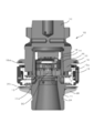
- FIG. 1 is a cross-sectional view of the tool holder unit 10 of the present invention
- FIG. 2 is an assembled disassembled perspective view showing a state in which the tool holder unit is divided
- FIG. 3 is a state immediately before the tool holder unit is connected. A cross section is shown.
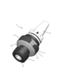
- FIG. 4 is a perspective view showing a state in which the tool holder unit 10 of the present invention is connected and a collet and a nut are attached to the chuck portion.
- the split tool holder unit 10 has a chuck portion 11 for gripping a rotating tool such as a cutting tool with a collet 28 and a nut 29 (see FIG. 4 (positions of reference numerals 17 and 18 in FIG. 1)), and rotation of a machining center or the like.
- the shank portion 12 gripped by the spindle of the processing apparatus (not shown, but located above FIG. 1) is connected in the vertical direction.
- the chuck portion 11 has an annular brim portion 20 protruding around the outer circumference at an intermediate position in the vertical direction. Below the brim portion 20, the shank side connecting portion 19 extends with a diameter reduced from that of the brim portion 20.
- a chuck-side connecting portion 21 that has a diameter reduced from the brim portion 13 and tapers upward extends, and the inside thereof has a cylindrical concave space 14 with an open upper portion.
- the concave space 14 is a space in which an electronic substrate or the like, which will be described later, is inserted and fixed.
- the shank portion 12 and the chuck portion 11 of the tool holder unit 10 are inserted by nesting the tapered recess 16 of the shank side connecting portion 19 over the tapered portion 15 of the chuck side connecting portion 21 until the lower end 19a abuts on the brim portion 13. They are connected to each other by (press fitting).
- a nut 29 having a hollow space 17 having an upwardly reduced diameter for inserting the collet 28 for gripping the rotating tool inside the chuck portion 11 and tightening the collet 28 from the outside to fix the rotating tool is provided.
- the nut connecting portion 24 to be mounted extends, and a brim portion 13 is provided at the base of the upper portion thereof. ..
- the chuck portion 11 is provided with an antenna unit 50 and a charging unit 60, and charges the outer cover member 52 of the antenna unit 50 forming a part of the outer surface of the chuck portion 11.
- the unit 60 and the outer cover member 62 are attached to the brim portion 13 at the base of the nut connecting portion 24, and the annular cover 26 arranged on the outer periphery of the brim portion 20 of the shank portion 12 and the nut connecting portion 24 is used from above and below. It is sandwiched and fitted and fixed.
- the annular cover 26 is made of aluminum and is fastened to the screw hole 27a of the chuck portion 11 with a fixing screw 27.
- FIG. 5 is a perspective perspective view showing a state in which the electronic substrate unit 30 is mounted in the concave space 14 provided in the chuck side connecting portion 21 of the chuck portion 11.
- FIG. 7 is an enlarged cross-sectional view of the vicinity of the connecting portion between the chuck portion 11 and the shank portion 12 in a state where the electronic substrate unit 30 is mounted.
- the chuck portion 11 and the shank portion 12 are inserted into the shank side connecting portion 19 in a nested manner, and the tapered portion 15 on the outer peripheral surface of the chuck side connecting portion 21 is inserted into the shank side connecting portion 19. It is connected by press-fitting into the tapered recess 16 on the inner peripheral surface of 19.
- the concave space 14 of the chuck-side connecting portion 21 has an opening at the top and a cylindrical recess at the bottom, and the electronic substrate unit 30 is inserted and fixed in the concave space 14.
- FIG. 6 shows a perspective view of the board mounting base 31.
- the substrate mounting base 31 is a disk-shaped member having a thickness made of an insulating material such as resin, and is lowered from above along the inner diameter of the concave space 14 of the chuck portion 11 in the thickness direction, and the bottom portion 31a is recessed. It is placed on the bottom 14a of the space 14. At this time, an adhesive is applied to the bottom portion 31a (or the bottom portion 14a) and fixed. Further, an adhesive is applied to the side portion 31b of the substrate mounting base 31, and the inner wall 14b of the concave space 14 is sufficiently fixed.
- the side portion 31b is provided with a plurality of grooves in the circumferential direction to improve the adhesiveness and prevent the adhesive from leaking out.
- the upper surface of the substrate mounting base 31 is provided with a counterbore 31f recessed downward, and an edge portion 31h is provided along the outer circumference of the counterbore 31f.
- the counterbore 31 serves as a space for receiving electronic components of the lowermost electronic substrate 31, which will be described later.
- a through hole 31c for the temperature sensor unit is provided so that the temperature sensor unit 35 can protrude from below.
- a pair of notches 31d are provided on the side portion of the board mounting base 31 at positions symmetrical with each other by 180 °, and each of them provides a space through which the antenna cable and the charging cable described later pass.
- edge portion 31h is provided with four support bases 31i for spacers (described later) fixed on the bottom layer electronic substrate 31 that has entered the spot facing portion 31f and protrudes in the radial direction at 90 ° intervals.
- a screw hole 31e is formed in the center of the carrier 31i.
- the counterbore 31f is provided with eight pin receiving holes 31g so that the sockets and pins for electrical connection between the electronic boards 32 to 34 (described later) do not come into contact with the total length of the electronic board unit 30. Is shortened.
- a first electronic substrate 31 (also referred to as "lowermost electronic substrate 31") of an insulating material such as resin is laminated on the first electronic substrate 31.
- An electronic component is mounted on the lower surface side of the first electronic substrate 31, is received by the counterbore 31f, and is adhesively fixed to the edge portion 31h.
- the first electronic substrate 31 is also provided with a through hole 32e, a pin receiving hole 32e, and a notch 32d so as to look into the screw hole 31e, the pin receiving hole 31e, and the notch 31d of the carrier 31i.
- upper layer electronic substrate 33 and “upper layer electronic substrate 33 lower electronic substrate” are laminated.
- the second electronic substrate 33 and the third electronic substrate 34 (also referred to as “upper layer electronic substrate 34" and “upper electronic substrate 34 among the upper electronic substrates") of the insulating material such as resin are the first electronic substrate. They are laminated on the 32 in order and fixed by adhesion. At this time, also in the second electronic board 33 and the third electronic board 34, through holes of the second electronic board 33 and the third electronic board 34 so as to look through the screw holes 31e, the pin receiving holes 31e, and the notch 31d of the carrier base 31i. 33e and 34e, pin receiving holes 33e, and notches 33d and 34d are provided.
- notches 32d and 33d of the other electronic boards 32 to 33 four notches 34d of the third electronic substrate 34 are provided in an arc shape along the outer circumference. Regarding this point, the battery It will be described later in the description of the unit holder 42.
- spacers 36 having the same height are vertically arranged above the second electronic substrate 33 at positions looking through the through holes 33e, and the third electronic substrate 34 is laminated above the spacers 36.
- substrate fixing screws 37 are arranged through the through holes 34e of the third electronic substrate 34 through the spacers 36 to through holes 33e to 36 to 33e and screwed to the screw holes 31e of the substrate mounting base 31, respectively. .. Since the spacer 36 and the substrate fixing screw 37 are made of a metal material such as SUS and have conductivity, they play a role of making electrical connections between the electronic components of the electronic substrates 32 to 34, and the electronic substrates 32 to 34 and the electrons. It has the role of securing space between parts and preventing heat conduction. It should be added that the role of preventing heat conduction is larger in the thick substrate mounting base 31.
- power supply terminals 38 for supplying electric power to the electronic boards 32 to 34 and electronic components are arranged.
- the power supply terminal 38 employs a leaf spring type in order to apply a reaction force upward to fix the power supply terminal 38 so that the electrode 41a of the battery unit 41, which will be described later, abuts and is electrically connected.
- FIG. 8 to 9 show an assembled disassembled perspective showing a structure in which the battery unit 41 is connected and fixed to the power supply terminal 38 of the uppermost electronic board 34 in a state where the electronic board unit 30 is fixed in the concave space 14 of the chuck portion 11.
- 8 is a view from above
- FIG. 9 is a view from below.
- the battery unit 41 is provided with a frame member 41c on the outer periphery of the disk-shaped rechargeable battery 41a, and the electrode 41b is exposed from the lower portion of the frame member 41a.
- a protrusion 41d that protrudes outward in the radial direction is provided on the outer periphery of the frame member 41c.
- the battery unit 41 is received by the battery unit holder 42 from above.
- the battery unit holder 42 is made of an elastic material having an insulating property such as resin, and is provided with a counterbore 42a having an opening at the top and recessed downward, and the inner diameter of the counterbore 42a is outside the battery unit 41.
- the battery unit 41 is received in the spot facing 42a so as to approximate the diameter.
- a large through hole 42b is formed in the center of the spot facing 42a, and when the battery unit 41 is received, the electrode 41b of the battery 41a is exposed downward. Further, a recess 42d is provided on the inner wall around the counterbore 42a of the battery unit holder 42 on the outer side in the radial direction, and when the battery unit 41 is received, the protrusion 41d fits into the recess 42d and rotates in the rotational direction. Positioned.
- the bottom of the battery unit holder 42 is provided with an arc-shaped convex portion 42c that projects downward around the outer peripheral edge portion.
- the central angles of the arcs of the convex portions 42 are different from 43 °, 40 °, 48 °, and 40 °.
- the notch portion 34d of the third electronic substrate 34 on the uppermost layer also has an arc shape, and its central angles are adjusted to 43 °, 40 °, 48 °, and 40 °.
- the battery unit holder 42 not only protects the battery 41a, which is a rechargeable secondary battery and tends to be more vulnerable to vibration and shock than the primary battery, but also the convex portion 42c and the concave portion 42d form a third electron.
- the notch 34d of the substrate 34 and the protrusion 41d of the battery unit 41 By positioning the notch 34d of the substrate 34 and the protrusion 41d of the battery unit 41, the electrode 41b of the battery 41a and the corresponding leaf spring type power supply terminal 38 can be assembled without mistake.
- the counterbore 42a of the battery unit holder 42 is provided with four semi-through holes 42e at positions where the substrate fixing screw 37 of the electronic substrate unit 30 is viewed, and the electronic substrates 32 to 34 are provided via the substrate fixing screw 37. Prevents electrical interference with.
- the battery unit holding member 43 is placed on the battery unit holder 42.
- the battery unit holding member 43 is formed of a sponge material (insulating elastic member) such as urethane foam, and when the shank side connecting portion 19 of the shank portion 12 is placed over the chuck side connecting portion 21 of the chuck portion 11 to be connected.
- the battery unit 41 is pressed downward while being inserted and compressed between the top surface of the tapered recess 16 of the shank portion 12 and the battery unit 41. Therefore, due to the elastic force and the insulating property of the battery unit pressing member 43, the battery unit 41 is pressed against the electronic substrates 32 to 34 while being insulated from the shank portion 12 and the chuck portion 11 to protect the battery unit 41 from vibration and impact. It is fixed in the vertical direction (the electrical connection between the electrode 41b and the power supply terminal 38 is also maintained).
- the tool holder unit 10 has an antenna unit 50 mounted on its chuck portion 11.
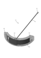
- 10 is a perspective view showing the configuration of the antenna unit 50 in an assembled state
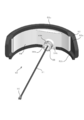
- FIG. 11 is an exploded perspective view of the antenna unit showing a state in which the outer cover member is attached
- FIG. 12 is a tool in the vicinity of the antenna unit 50.
- a partially enlarged cross-sectional view of the holder 10 FIG. 13 is an assembled disassembled perspective view of each component of the antenna unit 50
- FIG. 14 is a perspective view of the antenna unit 50 of FIG. 10 as viewed from the inner cover member 54 side.
- the antenna unit 50 is generally composed of an outer cover member 52, a substrate antenna 53, an inner cover member 54, an antenna cable 51, and a connector 55 in this order from the outside.
- the substrate antenna 53 is flexible (flexible) so that it can be arranged on the outermost circumference of the tool holder unit 10 in consideration of radio wave interference, noise generation, transmission capacity, etc. in the tool holder unit 10 which has a large environmental load and rotates at high speed.
- a plate-shaped antenna is used.
- the inner cover member 54 and the substrate antenna 53 are substantially arc-shaped members, and are formed with a curvature that can be attached to each other and conform to the outer cover member 52 described later.
- the inner cover member 54 is a resin material member that is injection-molded, and as shown in FIG.
- the entire back surface of the substrate antenna 53 is received and adhered to the surface on the outer cover member side (diameterally outside of the tool holder unit 10).
- a recess 54a is provided so that the recess 54a can be formed.
- a substantially cylindrical fitting boss 56 projects from the back surface of the inner cover member 54. As shown in FIGS. 14 and 12, the fitting boss 56 has a through hole 56a that penetrates the inner cover member 54 at the center thereof, and an annular groove 56b is provided on the outer peripheral wall. Has been done.
- the antenna cable 51 is inserted into the annular groove 56b and mounted on the back surface of the substrate antenna 53.
- the antenna cable 51 is attached to the back surface of the substrate antenna 53 by bending the tip of the antenna cable 51 at a gap between the back surface of the substrate antenna 53 and the recess 54a of the inner cover member 54. Then, an adhesive is filled inside the through hole 56a of the fitting boss 56, and the antenna cable 51 is fixed so as not to move by centrifugal force.
- the outer cover member 52 has an arc shape whose surface forms the outer surface of the chuck portion 11, and is made of an injection-moldable radio wave transmitting material such as resin.
- the back surface of the outer cover member 52 has a receiving surface 52a that abuts the entire surface of the inner cover member 54 on which the substrate antenna 53 is mounted on the edge portions 52c that are vertically arranged in an arc shape, and the inner cover 52a has an inner cover. The surfaces of the member 54 and the substrate antenna 53 are brought into contact with each other and fitted to the outer cover member 52 in the vertical direction.
- the adhesive is continuously applied to the edge of the surface of the inner cover member 54 in a frame shape to prevent the intrusion of cutting oil and the like and fix the adhesive.
- a thick portion 53a is formed on the outer cover member side, and a recess 52b is provided at a corresponding position of the outer cover member 52.
- the recess 52b is a portion that receives the thickness of the thick portion 53a of the substrate antenna 53 and the tip of the antenna cable 51 that is bent and mounted on the back surface of the substrate antenna 53.
- the inner cover member 54 has a protrusion 54b protruding upward along the upper edge portion thereof.
- the upper edge portion 52c of the outer cover member 52 has a notch portion 52d at a corresponding position.
- the outer cover member 52 and the inner cover member 54 are each made by injection molding, but both are formed in an arc shape of less than 180 °. This is because it is necessary to provide a so-called draft when extracting from the injection molding mold. This point is the same for the charging cover unit 60, and the existence of the key 70 and the positioning in the rotation direction due to the fact that the antenna unit 50 and the charging unit 60 cannot form 360 ° will be described later.
- the fitting boss 56 of the inner cover member 54 is inserted into the antenna hole 57 (see also FIG. 5) through which the concave space 14 of the chuck portion 11 communicates with the outside.
- An annular groove 56b is formed on the outer periphery of the fitting boss 56, and the fitting boss 56 is inserted into the antenna hole 57 with a packing such as an O-ring (not shown) attached to the annular groove 56b. It prevents cutting oil and the like from entering the concave space 14.
- the tool holder unit 10 has a charging unit 60 mounted on its chuck portion 11.
- 15 is an assembled and disassembled perspective view of each part of the antenna unit 50
- FIG. 16 is a perspective view showing the configuration of the assembled charging unit 60
- FIG. 17 is a tool holder unit 10 showing the vicinity of the charging unit 60. A partially enlarged cross-sectional view is shown.
- the charging unit 60 is generally composed of an outer cover member 62, a charging terminal board 63, an inner cover member 64, a charging cable 61, and a connector 65 in this order from the outside.
- the charging terminal board 63 fixes a terminal for supplying electric power from an external power source to the battery unit 41 (battery 41a) described above via a charging cable (electric cable) 61.
- the inner cover member 64 and the outer cover member 62 are substantially arc-shaped members, and are resin material members that are injection-molded with the same curvature as the inner cover member 54 and the outer cover member 52 of the antenna unit 50, respectively. As shown in FIG.
- the charging terminal board 63 is attached to the outer cover member 62 by a charging terminal 68 that fits and accepts the entire surface of the charging terminal board 63 on the back surface thereof and also serves as a fixing screw.
- a recess 62b is provided.
- Three through holes 63a and 62d are formed in the charging terminal substrate 63 and the recess 62b of the outer cover member 62 at positions where they can look into each other, and the charging terminal substrate 63 is passed through the through holes 63a and 62d. It is fixed to the recess 62b. At this time, the tip of the charging terminal 68 is exposed to the outside through the through hole 62d, and an external power plug is connected there. In this example, charging with a 3P power plug is assumed.
- a substantially cylindrical fitting boss 66 protrudes from the back surface of the inner cover member 64.
- the fitting boss 66 has a through hole 66a penetrating the inner cover member 64 at the center thereof, similarly to the fitting boss 56 (see FIG. 14) of the antenna unit 50 described above, and has an outer circumference.
- An annular groove 66b is provided on the wall.
- the charging cable 61 is inserted into the annular groove 66b and mounted on the back surface of the charging terminal board 6. To attach the charging cable 61 to the back surface of the charging terminal board 63, insert the tip of the charging cable 61 between the head 68a of the charging terminal 68 and the charging terminal board 63 when inserting and fixing the charging terminal 68 into the through hole 63a.
- the inner cover member 62 is attached to the outer cover member 62 in a state where the charging terminal board 63 and the charging cable 61 are fixed to the outer cover member 62.
- the outer cover member 62 has an arc shape whose surface forms the outer surface of the chuck portion 11, and is made of an injection-moldable material such as resin.
- the back surface of the outer cover member 62 has a receiving surface 62a for abutting and adhering the entire surface of the inner cover member 64 in a state where the charging terminal substrate antenna 63 is fixed to the frame-shaped edge portion 62c surrounding the periphery.
- the inner cover member 64 is fixed to the outer cover member 62.
- the fitting boss 66 of the inner cover member 64 is inserted into the charging cable hole 67 (see also FIG. 5) through which the concave space 14 of the chuck portion 11 communicates with the outside.
- An annular groove 66b is formed on the outer periphery of the fitting boss 66, and the fitting boss 66 is inserted into the charging cable hole 67 with a packing such as an O-ring (not shown) attached to the annular groove 66b. , Prevents cutting oil and the like from entering the concave space 14.
- FIG. 18 shows a perspective view of a state in which the antenna unit 50 and the charging unit 60 are attached to the chuck portion 11.
- the antenna unit 50 and the charging unit 60 are mounted by sandwiching the brim portion 13 of the chuck portion 11 between the edge portions 52c and 62c of the outer cover members 52 and 62.
- the outer cover member 62 and the inner cover member 64 are formed in an arc shape of less than 180 ° for convenience of injection molding, and the antenna unit 50 and the charging unit 60 cannot form 360 ° around the outer circumference.
- the small cover member 70 made of aluminum alloy is adopted in consideration of strength, lightness, workability and decorativeness.
- connecting shaft members 21a are arranged on the upper surface of the brim portion 13 of the chuck portion 11.
- the chuck portion 11 is connected to the shank portion 12 by inserting the connecting shaft member 21a into the connecting hole 19c (see FIG. 2) formed in the lower end 19a of the shank connecting portion 19 of the shank portion 12.
- a substantially annular key 71 is fitted and inserted into a pair of connecting shaft members 21a arranged at positions rotated by approximately 90 ° from the antenna hole 57 and the charging cable hole 67 of the connecting shaft member 21a.
- Each of the keys 71 is provided with a protrusion 71a that projects outward in the radial direction.
- the small cover member 70 is provided with a fitting recess 70a on the inner side surface in the radial direction, and the protrusion 71a of each key 71 is fitted and positioned in the fitting recess 70a. Therefore, when the small cover member 70 is assembled between the outer cover members 52 and 62, the positioning of the outer cover members 52 and 62 in the rotation direction can be achieved by the small cover member 70, and fatigue due to repeated deceleration and acceleration during high-speed rotation can be achieved. The small cover member 70 can catch it, and fatigue failure of the resin outer cover members 52 and 62 can be prevented.
- the corresponding connection hole 19b of the shank side connecting portion 19 is provided with a recess 19C so as to have a height different from the others.
- the annular cover 26 is inserted around the nut connecting portion 24 from below with the outer cover members 52, 62 and the small cover member 70 assembled to the chuck portion 11.
- Four through holes 26a and connecting holes 13a are bored at positions where the annular cover 26 and the brim portion 13 look into each other at substantially the same intervals in the rotational direction, and the through holes are formed when the annular cover 26 is attached to the brim portion 13.
- the fixing screw 27 is inserted into the connecting hole 13a at 26a and fixed. Further, as shown in FIGS.
- the outer peripheral edge portion 19d of the brim portion 19 of the chuck portion 11 protrudes downward (hangs down), and the outer peripheral edge portion 26b of the annular 26 protrudes upward (stands up). There is. Therefore, when the chuck portion 11 and the annular cover 26 are connected to the shank portion 12, the outer peripheral edges 19d and 26b fit into the upper and lower edge portions 52c and 62c of the outer cover members 52 and 62 (and the small cover member 70). In addition, it prevents fixing and loosening in the vertical direction.
- FIG. 1 shows a cross-sectional view of the tool holder unit 10 in which the collet 28, the nut 29, and the rotary tool 72 are omitted, but FIG. 19 shows the collet 28, the nut 29, and the rotary tool 72 (hereinafter, also referred to as “rotary tool 72”).
- FIG. 19 shows the collet 28, the nut 29, and the rotary tool 72 (hereinafter, also referred to as “rotary tool 72”).
- a cross-sectional view of the tool holder unit 10 provided with (referred to as) is shown.
- FIG. 19 is mainly referred to.
- 20A and 20B are vertical cross-sectional views of the temperature sensor unit 35, where FIG. 20A shows a state when uncompressed and FIG. 20B shows a state when compressed.
- FIG. 21A and 21B show the vicinity of the movable substrate 35c in the tubular main body 35b of the temperature sensor unit 35, where FIG. 21A is a partially transparent perspective view and FIG. 21B is a partial cross-sectional view.
- FIG. 22 shows an assembled disassembled perspective view of the temperature sensor unit 35 and the tool holder unit 10 in the state where the collet 28, the nut 29, and the rotating tool 72 are not provided in (a), as viewed from below (b) and (c). ) Show transparent perspective views of the temperature sensor unit 35 viewed from diagonally above and diagonally below, respectively.
- FIG. 23 is a partial cross-sectional view of the tool holder unit 10 in the vicinity of the temperature sensor unit 35, and for convenience of explanation, the internal structure of the temperature sensor unit 35 is a perspective view.
- the temperature sensor unit 35 is electrically connected to a substantially hollow tubular main body 25b, a flange 35a forming an annular flange at the base thereof, and one end of the movable substrate 35c inside the tubular main body 25b.
- a thermocouple 75 (covered with a sheath 73) whose other end is inserted and fixed at a temperature measurement point in the rotary tool 72, a screw portion 35d that protrudes downward from the flange portion 35a and has a through hole inside, and a tubular main body portion.
- a terminal board 35e that is abutted and fixed to the top surface (upper surface) of 25b and electrically connected to the movable board 35c, a pin member 35f as a guide element that brings the movable member 35c closer to and separated from the terminal board 35d, and a pin member 35f. It is composed of a coil spring 35g which is arranged around the above and generates a reaction force while electrically connecting the movable substrate 35c and the terminal substrate 35e.
- the tip of the thermocouple 75 extending from the temperature measurement point inside the rotary tool 72 held by the collet 28 arranged inside the nut connecting portion 24 is an electronic substrate (this). In the example, it is connected to the electronic component of the second electronic board 33), but the temperature sensor unit 35 is used to connect the thermocouple 75 and the second electronic board 33.
- through holes 14c, 31c, 32e for the temperature sensor unit are located at the centers of the bottom portion 14a of the concave space 14 of the chuck portion 11 on which the electronic substrate unit 30 is placed and fixed, the substrate mounting base 31, and the first electronic substrate 32e, respectively.
- the above-mentioned through hole 32e) is drilled, and the tubular main body 35b of the temperature sensor unit 35 is inserted from below the inside of the nut connecting portion 24, and the upper end is a concave space through the through holes 14c, 31c, 32e for the temperature sensor unit. It projects to the vicinity of the lower surface of the second electronic substrate 33 in 14.
- the flange portion 35a at the base of the tubular main body portion 35b serves as an upward stopper and comes into contact with the bottom portion 14a of the concave space 14.
- the inside of the tubular main body 35b has a cylindrical space, and the upper surface is formed as a lid member that closes the upper part of the internal space, and has a disk shape that serves as an electrical contact with the second electronic substrate 33.
- Terminal board 35e is mounted. As shown in FIG. 22B, the terminal board 35e has a conductive portion 35h, which is an electrical contact, formed in a ring shape concentric with the center of the shaft. As a result, the temperature sensor unit 35 can be electrically connected to the second electronic substrate 33 at any angle.
- the internal space of the tubular main body 35b is vertically connected by a pin member 35f from the bottom thereof to the terminal board 35. As shown in FIG.
- a movable substrate 35c is slidably mounted on the pin member 35f along the pin member 35f, and a metal or the like is conductive around the pin member 35f between the movable substrate 35c and the terminal substrate 35e.
- a coil spring 35 g of the material is arranged. Therefore, when a force for pushing up the movable substrate 35e from below is applied, the coil spring 35g is compressed (see FIG. 20B), and when the force for pushing up is eliminated (or a force for pushing up) is applied, the coil spring 35g is extended to the movable member 35e. It moves and returns to its original position (or moves to a lower position (see FIG. 20A)).
- the vertical movement of the movable substrate 35c is performed by following the invasion of the pipe member 74.
- the pipe member 74 is a tubular member, the tip of which is inserted and fixed from below the movable substrate 35c and protrudes upward, and the lower end of the pipe member 74 passes through a through hole in the screw portion 35d and is inserted into the rotary tool 72. It is fixed. Therefore, when the pipe member 74 connected to the rotary tool 72 is pushed upward, the movable substrate 35c interlocking with the pipe member 74 is pushed up along the pin member 35f while resisting the repulsive force of the coil spring 35g, and conversely, the pipe member 74. Is pulled down, the movable substrate 35c is pulled down along the pin member 35f.
- thermocouple 75 (including a wire thereof) is inserted inside the pipe member 74 over the entire longitudinal direction, and both ends of the thermocouple 75 protrude from the pipe member 74.
- the upper end of the thermocouple 75 protrudes from the pipe member 74 protruding from the movable substrate 35c, and the upper end thereof is attached to the conductive portion 35j (thin film or the like) of the movable substrate 35c by the connecting wire 35i. It is electrically connected.
- the conductive portion 35j is electrically connected to the lower end of the coil spring 35g, and the upper end of the coil spring 35g is connected to the conductive portion 35h of the terminal board 35e.
- thermocouple 75 the sheath 73, and the pipe member 74 are seated with the chuck portion 11.
- the conductive portion 35h of the terminal board 35e is formed of a central circle and its concentric ring, and the conductive portion 35h is electrically connected to a connection terminal arranged on the lower surface of the third electronic board 33.
- FIG. 24 shows a schematic cross-sectional view of the tool holder unit 10 when a flow path for cooling oil (hereinafter, also referred to as “coolant”) is provided inside.
- the tool holder unit 10 has a structure in which coolant is discharged from the tip (lower end) of the rotary tool 72 through the internal flow paths of the shank portion 12, the chuck portion 11, and the rotary tool 71 from the spindle of the machining apparatus (arrow A). -See arrow F). First, the coolant flows into the main flow path 80 connected to the coolant flow path (not shown) of the main shaft (see arrow A).
- the main flow path 80 is bored downward from the upper end of the shank portion 12 along the rotation axis.
- the coolant that has passed through the main flow path 80 flows into a plurality of first flow paths 81 that extend radially from the main flow path 80 in the outer peripheral direction (see arrow B).
- the first flow path 81 is created by drilling from the outside to the inside in the radial direction to the main flow path 80, and is sealed from the outside by a set screw 85.
- the second flow path 82 is formed by bending downward on the radial outer side of each first flow path 81, and extends downward from the inside of the wall thickness of the shank-side connecting portion 19 of the shank portion 12 to the bottom portion 19a thereof. As shown in FIG. 2, the second flow path 82 is created by drilling the inside of the wall thickness from the bottom 19a side of the shank side connecting portion 19 to the first flow path 81.
- the outlet 82a of the second flow path 82 forms a spot facing around it, and an O-ring 82b having a thickness that protrudes to the outside when mounted on the spot facing is mounted.
- the coolant that has flowed through the second flow path 82 flows into the third flow path 83 that is fluidly connected to the second flow path 82.
- the third flow path 83 extends downward in the thickness direction inside the brim portion 13 of the chuck portion 11, and is connected to the fourth flow path 84 below the brim portion 13.
- the fourth flow path 84 is bent inward in the radial direction at the lower end of the third flow path 83, and extends in four radial directions toward the center (see arrow D).
- the fourth flow path 84 is perforated from the outside to the inside in the radial direction, and is sealed from the outside with a set screw 86.
- the third flow path 83 is created by drilling from above the brim portion 13 to the fourth flow path 84 in a state where the fourth flow path 84 is perforated. Then, the coolant that has flowed to the fourth flow path 84 flows into the space 88 below the plate nut (see FIG. 22A) that supports the flange portion 35a of the temperature sensor unit 35, and spirals in the rotary tool 71. It flows into the shaped flow path 72b (see arrow E) and is discharged from the lower end of the rotary tool 72 (see arrow F).
- An annular O-ring 87 is inserted between the flange portion 35a of the temperature sensor unit 35 and the bottom portion 14a of the concave space 14. The O-ring 87 is fixed on a flat surface in consideration of workability at the time of mounting and reduction of the total length of the tool holder unit 10.
- the partial cross-sectional view of FIG. 25 shows a structure for preventing coolant from entering the temperature sensor unit 35.
- the thermocouple 75 (and the sheath 73, the pipe member 74) is slidably inserted into the through hole 35 m inside the screw portion 35d, and the upper end thereof is inside the tubular main body portion 35b. It is projected to. Therefore, it is necessary to prevent the coolant from entering the inside of the tubular main body 35b through the through hole 35m of the screw 35d.
- an annular O-ring 80, a washer 81, and an O-ring 82 through which the pipe member 74 is passed are arranged in the through hole 35 m. By sandwiching the metal washer 81 between the resin O-rings 80 and 82, it is possible to prevent the pipe member 74 from sliding up and down, deforming the O-ring within the through hole 35 m, and reducing the sealing effect. There is.
- this tool holder unit also has a set screw 96 that plays a role of weight adjustment.
- the tool holder unit 10 rotates at a high speed, and if the weight balance in the radial direction is unbalanced, extra vibration and stress are generated, which leads to a decrease in accuracy as a measuring device.
- a set screw 96 is used as an adjusting element for weight balance. As an example, FIG.
- FIG. 26 shows a schematic cross-sectional view in which the shank portion 12 is cut in the horizontal direction at the height of the set screw 96 (see reference numeral 96 in FIG. 2).
- a screw hole 95 into which a set screw 96 can be inserted / fastened is drilled on the outer periphery of the shank portion 12.
- four screw holes 95 are provided at 90 ° intervals. This is to adjust the weight balance in the XY directions.
- FIG. 26A shows an example in which the weight in the XY direction is unbalanced in the state where the set screw is not inserted (left figure), and the set screws 96a to 96d made of steel having different lengths are used.
- ⁇ M5, density 7.9 g / cm2) is inserted into the screw holes 96a to 96d to adjust the weight balance in the XY directions (right figure).
- FIG. 26B the same steel retaining screws 96a to 96c as in FIG. 26A having different lengths were inserted into the screw holes 96a to 96c, and the weight balance could be adjusted in the Y direction.
- Recessed portion 52c ... Edge portion 52d ... Notch 53 ... Board antenna 53a ... Thick part 54 ... Inner cover member 54a ... Recessed 54b ... Protrusion 55 ... Connector 56 ... Fitting boss 56a ... Through hole 56b ... Circular groove 57 ... Antenna hole 60 ... Charging unit 61 ... Charging cable 62 ... Outer cover member 62a ... Receiving surface 62b ... Recessed portion 62c ... Edge 62d ... Through hole 63 ... Charging terminal board 63a ... Through hole 64 ... Inner cover member 65 ... Connector 66 ... Fitting boss (boss) 66a ... Through hole 66b ... Circular groove 67 ...
- Charging cable hole 68 Charging terminal 68a ... Head 70 ... Small cover member 70a ... Fitting recess 71 ... Key (key member) 71a ... Protrusion 72 ... Rotating tool (rotating tool) 72a ... Through hole (semi-through hole) 72b ... Flow path (fourth flow path) 73 ... Sheath 74 ... Pipe member (tubular member) 75 ... Thermocouple (including its wire) 76 ... Plate nut 80 ... Main flow path 81 ... First flow path 82 ... Second flow path 82a ... Outlet 82b ... O-ring 83 ... Third flow path 84 ... Fourth flow path 85 ... Fastening screw 86 ...
Abstract
[Problem] To provide a substantially cylindrical tool holder unit that detects, on a real-time basis, temperature information and/or vibration information of a rotary tool during machining by a rotary machining device, and transmits the temperature information and/or vibration information wirelessly to the outside. [Solution] This tool holder unit, which grips a rotary tool on a lower chuck portion side and is gripped by a main shaft of a rotary machining device on an upper shank portion side, is provided with: an electronic substrate unit mounted in an internal space to receive and transmit at least temperature information and/or vibration information of the rotary tool; and an antenna unit that receives the temperature information and/or the vibration information from the electronic substrate unit by way of an antenna cable and transmits the information wirelessly to the outside. The antenna unit comprises: an outer cover member of a radiowave-transmissive insulating material which, in a state in which the inside thereof is sealed off from the outside, is attached to an outer periphery of the tool holder unit, the outer cover member having a radially outside surface forming a semicircular arc shape continuous with an outer peripheral surface of the tool holder unit; an inner cover member attached to the outer cover member from a radially inner side and forming a semicircular arc shape; and a substrate antenna which is a substantially plate-like flexible member having a radially inner surface to which an end portion of the antenna cable passed from the radially inner side to a radially outer side of the inner cover member is connected, wherein the substrate antenna, in a state of being attached to the radially outer side of the inner cover member, is sealed and attached inside a gap between the inner cover member and the outer cover member.
Description
本発明は、切削加工装置等の回転加工装置の回転ツールの温度及び/又は振動をリアルタイムに検知する略筒状のツールホルダユニットの構造に関するものである。
The present invention relates to a structure of a substantially tubular tool holder unit that detects the temperature and / or vibration of a rotating tool of a rotating processing device such as a cutting device in real time.
切削加工装置等の回転加工装置において、被加工物の製品精度や製造効率、加工製品の歩留まりを考慮すると加工時の工具の状態の評価、例えば摩耗や疲労、破損、びびり等の評価することが要求される。従来、ツール評価は、装置メーカや工具メーカがその装置や工具ごとに一般化する評価基準、学術的に標準化された評価に基づいて行われていた。これに対して加工時における実際の工具についてのリアルタイム検証はできていなかった。
In rotary machining equipment such as cutting equipment, it is possible to evaluate the state of the tool during machining, such as wear, fatigue, breakage, chatter, etc., in consideration of the product accuracy and manufacturing efficiency of the workpiece and the yield of the machined product. Required. Conventionally, tool evaluation has been performed based on evaluation criteria generalized by equipment makers and tool makers for each device and tool, and academically standardized evaluation. On the other hand, real-time verification of the actual tool at the time of machining has not been possible.
これに対して出願人は回転ツール(以下、「回転工具」とも称す)の加工中の温度測定し得るツールホルダユニットを開発・提供し、この測定結果に基づく異常予知技術についても開発・提供してきた(特許文献1、特許文献2参照)。また、工具の破損等の重要な要因として温度以外に振動や応力があることも知られている。出願人は、この点にも注目しており、回転工具の異常振動を前記ツールホルダでリアルタイムに検出し無線送信を介して外部ユニットで分析し得る技術を開発し、提供している(特許文献3、特許文献1等参照)。
In response to this, the applicant has developed and provided a tool holder unit capable of measuring the temperature during machining of a rotating tool (hereinafter, also referred to as "rotating tool"), and has also developed and provided an abnormality prediction technology based on this measurement result. (See Patent Document 1 and Patent Document 2). It is also known that vibration and stress other than temperature are important factors such as tool breakage. The applicant is also paying attention to this point, and has developed and provided a technique capable of detecting abnormal vibration of a rotary tool in real time with the tool holder and analyzing it with an external unit via wireless transmission (Patent Document). 3. Refer to Patent Document 1 etc.).
従来のツールホルダユニットの場合、電子基板や充電式バッテリは高速回転するツールホルダの内部に搭載され、測定装置としての精度を向上するには大きな遠心力や電子基板から外部及び外部部品までの出力電波の低下・減衰、干渉によるノイズ発生の問題を考慮する必要があった。また、ツールホルダの内部に搭載される測定データを処理する電子部品や充電バッテリに接続される無線送信のアンテナやバッテリへの充電装置は、アクセスの便宜上、外部に搭載することが望ましい。その一方、ツールホルダユニットの外部は、高温・高圧・高速の切削油や切り屑、冷却水等が降りかかり、これらから無線通信機器や充電バッテリへの電力供給端子、内部の電子基板を保護する必要がある。また、大きな遠心力に耐え得る固定力を有する必要もある。加えて無線通信機器はこのような厳しい環境下で電波を外部に十分に飛ばすことが要求される。
In the case of a conventional tool holder unit, the electronic board and rechargeable battery are mounted inside the tool holder that rotates at high speed, and in order to improve the accuracy as a measuring device, a large centrifugal force or output from the electronic board to external and external parts is required. It was necessary to consider the problems of noise generation due to deterioration / attenuation of radio waves and interference. Further, it is desirable that the electronic component for processing the measurement data mounted inside the tool holder, the antenna for wireless transmission connected to the charging battery, and the charging device for the battery are mounted externally for convenience of access. On the other hand, the outside of the tool holder unit is exposed to high-temperature, high-pressure, high-speed cutting oil, chips, cooling water, etc., and it is necessary to protect the power supply terminals for wireless communication equipment and charging batteries, and the internal electronic board. There is. It also needs to have a fixing force that can withstand a large centrifugal force. In addition, wireless communication devices are required to sufficiently emit radio waves to the outside in such a harsh environment.
また、特に後述する分割式ツールホルダの場合は、本来、分割部品の連結位置で切削液等が外部から侵入し易い構造であり、分割式であっても十分な防水・防滴効果を有し、耐遠心力の構造にする必要がある。さらに、回転ツール内の熱電対からのデータをツールホルダユニット内の電子基板に装着する電子部品で受信・処理する場合に、熱電対の素線を直接、内部の電子基板に接続することによる弊害も考慮される。
Further, particularly in the case of the split type tool holder described later, the structure is originally such that cutting fluid or the like easily enters from the outside at the connecting position of the split parts, and even if the split type has a sufficient waterproof / drip-proof effect. , It is necessary to have a centrifugal force resistant structure. Furthermore, when the data from the thermocouple in the rotating tool is received and processed by the electronic component mounted on the electronic board in the tool holder unit, the harmful effect of connecting the wire of the thermocouple directly to the internal electronic board. Is also considered.
このような事情に鑑みて本発明は創作されたものであり、回転加工装置の主軸に取り付け回転ツールの温度・振動等をリアルタイム測定し得るツールホルダユニットにおいて、高速回転中に高精度に無線送信することができ、外部の切削油等の侵入を防ぎながら温度測定することができ、充電や組立作業が容易であるツールホルダユニットの好適な構造を提供することを目的とする。
The present invention was created in view of such circumstances, and is a tool holder unit that is attached to the spindle of a rotary processing apparatus and can measure the temperature, vibration, etc. of a rotary tool in real time, and wirelessly transmits with high accuracy during high-speed rotation. It is an object of the present invention to provide a suitable structure of a tool holder unit which can measure the temperature while preventing the intrusion of cutting oil and the like from the outside and is easy to charge and assemble.
アンテナユニット
具体的に本発明は、
回転加工装置による加工中の回転ツールの温度情報及び/又は振動情報をリアルタイムに検知し、外部に無線送信する略筒状のツールホルダユニットであって、
該ツールホルダユニットは、下方のチャック部側で回転ツールを把持し、上方のシャンク部側で回転加工装置の主軸に把持されるものであり、内部の空間に装着されて回転ツールの少なくとも温度情報及び/又は振動情報を受信し、送信する電子基板ユニットと、該電子基板ユニットからの前記温度情報及び/又は振動情報をアンテナケーブルを介して受信し、外部に無線送信するアンテナユニットとを備え、
前記アンテナユニットは、外部から内部を封止した状態で前記ツールホルダユニットの外周に装着される。 Antenna unit Specifically, the present invention
A substantially tubular tool holder unit that detects temperature information and / or vibration information of a rotating tool being machined by a rotary processing device in real time and wirelessly transmits it to the outside.
The tool holder unit grips the rotary tool on the lower chuck portion side and is gripped on the spindle of the rotary processing device on the upper shank portion side, and is mounted in the internal space to provide at least temperature information of the rotary tool. An electronic board unit that receives and / or receives and transmits vibration information, and an antenna unit that receives the temperature information and / or vibration information from the electronic board unit via an antenna cable and wirelessly transmits the vibration information to the outside.
The antenna unit is mounted on the outer periphery of the tool holder unit with the inside sealed from the outside.
さらに、本ツールホルダユニットは、
その径方向外側の表面が前記ツールホルダユニットの外周表面と連続する半円弧形状を形成し、電波透過性を有する絶縁材料の外側カバー部材と、
該外側カバー部材に径方向内側から装着されて半円弧形状を形成する内側カバー部材と、
該内側カバー部材の径方向内側から外側に通されたアンテナケーブルの端部を径方向内側面で接続する可撓性を有する略板状部材であり、前記内側カバー部材の径方向外側に装着させた状態で該外側カバー部材との隙間内に封止装着される基板アンテナと、を有する。 Furthermore, this tool holder unit is
The outer surface of the radial outer surface forms a semicircular arc shape continuous with the outer peripheral surface of the tool holder unit, and the outer cover member of the insulating material having radio wave transmission is
An inner cover member that is attached to the outer cover member from the inside in the radial direction to form a semicircular arc shape,
It is a substantially plate-shaped member having flexibility that connects the end portions of the antenna cables passed from the radial inside to the outside of the inner cover member on the radial inner side surface, and is mounted on the radial outer side of the inner cover member. It has a substrate antenna that is sealed and mounted in a gap between the outer cover member and the outer cover member.
本ツールホルダユニットでは、温度データや振動データ等を受信処理する電子基板ユニットをツールホルダユニットの内部の空間内に配設し、電子基板ユニットが受信した温度データ等を外部送信するアンテナユニットを電子基板ユニットから分離してツールホルダユニットの外周に設けている。これにより内部及び周辺に干渉部材が多数近接する状態で高速回転しているツールホルダユニットから回転ツールの情報を無線送信しても干渉によるノイズ等を低減して高精度に送信することができる。また、アンテナユニットを外周に設ける構成として、円筒状のツールホルダユニットの外周と一体化し、高速回転時の余分な振動や負荷を低減しつつ切削油等の侵入を防止する構成を採用しており、具体的には、ツールホルダユニットの外表面と連続する外側カバー部材の内側とこれと封止装着される内側カバー部材の外側とで形成される隙間内に板状の基板アンテナを撓ませて封入することとしている。なお、本アンテナユニットは部品を径方向に重ねるだけで作成できるので組立性も良好である。
In this tool holder unit, an electronic board unit that receives and processes temperature data, vibration data, etc. is arranged in the space inside the tool holder unit, and an antenna unit that externally transmits the temperature data, etc. received by the electronic board unit is electronic. It is separated from the board unit and provided on the outer circumference of the tool holder unit. As a result, even if the information of the rotating tool is wirelessly transmitted from the tool holder unit rotating at high speed with a large number of interfering members close to the inside and the periphery, noise due to interference can be reduced and transmitted with high accuracy. In addition, as a configuration in which the antenna unit is provided on the outer circumference, it is integrated with the outer circumference of the cylindrical tool holder unit to reduce excess vibration and load during high-speed rotation and prevent the intrusion of cutting oil, etc. Specifically, the plate-shaped substrate antenna is bent in the gap formed between the inside of the outer cover member continuous with the outer surface of the tool holder unit and the outside of the inner cover member to be sealed and mounted. It is supposed to be enclosed. Since this antenna unit can be created simply by stacking parts in the radial direction, the assembling property is also good.
代表的な本ツールホルダユニットでは、
前記内側カバー部材は、径方向外側表面に前記基板アンテナの径方向内側表面を当接受容する凹部と、上縁部から突出する突起とを有し、
前記基板アンテナは、径方向内側を前記内側カバー部材の凹部に当接受容させ、周方向の一部が径方向外側に厚みが大きくなる厚肉部を有し、
前記外側カバー部材は、上縁部及び下縁部に沿って径方向内側に起立する枠部材と、該枠部材の上下間の径方向内側で前記基板アンテナの径方向外側を当接受容する受容面と、前記枠部材の一部で前記内側カバー部材の突起を嵌合受容する切欠き部と、前記基板アンテナの厚肉部を嵌合受容する凹部と、を有し、
前記内側カバー部材の凹部に基板アンテナが受容固定させた状態で、該内側カバー部材の突起と前記基板アンテナの厚肉部とを、それぞれ前記外側カバー部材の切欠き部と凹部とに嵌合させて前記内側カバー部材と前記外側カバー部材とを接着固定する。 In this typical tool holder unit,
The inner cover member has a concave portion that abuts and receives the radial inner surface of the substrate antenna on the radial outer surface, and a protrusion that protrudes from the upper edge portion.
The substrate antenna has a thick portion in which the inside in the radial direction is abutted and received by the recess of the inner cover member, and a part in the circumferential direction is thickened outward in the radial direction.
The outer cover member is a receiver that abuts and receives a frame member that stands up radially inward along the upper edge portion and the lower edge portion and the radial outer side of the substrate antenna on the radial inside between the upper and lower sides of the frame member. It has a surface, a notch portion that fits and receives a protrusion of the inner cover member in a part of the frame member, and a recess that fits and receives a thick portion of the substrate antenna.
While the substrate antenna is received and fixed in the recess of the inner cover member, the protrusion of the inner cover member and the thick portion of the substrate antenna are fitted into the notch and the recess of the outer cover member, respectively. The inner cover member and the outer cover member are bonded and fixed.
また、本発明のツールホルダユニットは、
前記電子基板ユニットを装着するツールホルダユニットの内部の空間から外部に連通するアンテナ用孔を有し、
前記内側カバー部材の径方向内側には、内外側に貫通する貫通孔と、外周に沿った環状溝を有して、前記アンテナ用孔に挿入固定される略円筒状のボスが突出し、
前記アンテナケーブルは、前記電子基板ユニットから前記アンテナ用孔に挿入固定された前記ボスの貫通孔を通して前記基板アンテナに装着され、
前記アンテナ用孔の内壁と前記ボスの環状溝との間にはOリングが配設され、前記ボスの貫通孔と前記アンテナケーブルとの間には接着剤が充填される、ことが好ましい。 Further, the tool holder unit of the present invention is
It has an antenna hole that communicates from the space inside the tool holder unit on which the electronic board unit is mounted to the outside.
A substantially cylindrical boss that has a through hole penetrating the inside and outside and an annular groove along the outer circumference and is inserted and fixed in the antenna hole protrudes inside the inner cover member in the radial direction.
The antenna cable is attached to the substrate antenna from the electronic substrate unit through the through hole of the boss inserted and fixed in the antenna hole.
It is preferable that an O-ring is disposed between the inner wall of the antenna hole and the annular groove of the boss, and an adhesive is filled between the through hole of the boss and the antenna cable.
このアンテナユニットによれば、内側カバー部材からアンテナケーブル装着用のボスが突出し、このボスをツールホルダユニット側のアンテナ用孔に挿入して固定することで最短距離で容易に基板アンテナから電子基板ユニットまでの接続をすることができる。特にアンテナ用孔は外部から電子基板ユニットがある空間まで穿孔するだけで作成でき、電子基板を組み付けながら、電子基板と接続するアンテナケーブルの先端をアンテナ用孔から出しておけば、ボスを通して基板アンテナに接続させてアンテナユニットを組み付けるだけで容易に無線送信構造を作ることができ、ツールホルダユニットの組付作業が容易になり汎用性が大幅に向上する。さらに、ボスとアンテナ用孔を封止するだけで電子基板ユニット及びアンテナユニット内に切削油等が侵入することも防止できる点でも有利な構造である。
According to this antenna unit, a boss for mounting the antenna cable protrudes from the inner cover member, and by inserting this boss into the antenna hole on the tool holder unit side and fixing it, the electronic board unit can be easily removed from the board antenna in the shortest distance. Can be connected up to. In particular, the antenna hole can be created by simply drilling from the outside to the space where the electronic board unit is located. If the tip of the antenna cable connected to the electronic board is pulled out from the antenna hole while assembling the electronic board, the board antenna will be passed through the boss. A wireless transmission structure can be easily created simply by connecting to the antenna unit and assembling the antenna unit, which facilitates the assembly work of the tool holder unit and greatly improves versatility. Further, it is an advantageous structure in that cutting oil or the like can be prevented from entering the electronic substrate unit and the antenna unit only by sealing the boss and the antenna hole.
充電ユニット
また、本ツールホルダユニットにおいて、
前記アンテナユニットと同じ水平面上で同じツールホルダユニットの外周表面を形成するようにツールホルダユニットに装着される充電ユニットを備え、該充電ユニットは、
前記電子基板ユニットに接続し電力供給するバッテリに接続してその充電用に電力供給する充電ケーブルと、
その径方向外側の表面が前記ツールホルダユニットの外周表面と連続して前記アンテナユニットと同曲率を有する半円弧形状を形成する絶縁材料の外側カバー部材と、
該外側カバー部材に径方向内側から装着される半円弧形状を形成する内側カバー部材と、
該内側カバー部材の径方向内側から外側に通された充電ケーブルの端部を径方向内側面で接続する略板状部材であり、固定ビスにより前記外側カバー部材の径方向内側に装着固定する端子基板とを備え、
該固定ビスの先端は、前記外側カバー部材から外部に露出して外部から電力の供給を受ける電気端子となる、構成も提供される。 Charging unit In addition, in this tool holder unit,
The charging unit includes a charging unit mounted on the tool holder unit so as to form the outer peripheral surface of the same tool holder unit on the same horizontal plane as the antenna unit.
A charging cable that connects to the electronic board unit and supplies power to the battery and supplies power for charging the battery.
An outer cover member of an insulating material whose radial outer surface is continuous with the outer peripheral surface of the tool holder unit and forms a semicircular arc shape having the same curvature as the antenna unit.
An inner cover member forming a semi-circular shape, which is attached to the outer cover member from the inside in the radial direction,
A substantially plate-shaped member that connects the end portions of the charging cable passed from the radial inside to the outside of the inner cover member on the radial inner side surface, and is a terminal that is mounted and fixed on the radial inside of the outer cover member by a fixing screw. Equipped with a board,
A configuration is also provided in which the tip of the fixing screw is exposed to the outside from the outer cover member and serves as an electric terminal that receives power from the outside.
本充電ユニットは、ツールホルダユニットの内部の空間内に配設された電子基板ユニットの電源となる充電バッテリに外部から充電用の電力を供給する充電ユニットである。ツールホルダユニットではツールホルダユニット内の空間に電子基板ユニットとンバッテリとを順に配設し、電子基板ユニット及び充電バッテリと分離して分離して充電ユニットをツールホルダユニットの外周に設け、充電ケーブルの電気端子をツールホルダユニットの外周に露出させている。また、本充電ユニットの外側カバー部材がアンテナユニットの外側カバー部材と共にツールホルダユニットの外周表面の一部を形成するため高速回転中に環境周辺の部材とも干渉せず、重量バランス及び余分な振動・負荷の防止の視点からアンテナユニットとの組み合わせの相性が良好である。また、充電ケーブルの先端と電気接続及び固着する端子基板の固定ビスを外側カバー部材への固定の役割と、外部プラグと接続し電力の供給を受けるための電気端子としての役割を兼務させているので、部品点数の低減及びスペースの縮小化を図ることもできる。さらに、本充電ユニットは部品を径方向に重ねるだけで作成できるので組立性も良好である。
This charging unit is a charging unit that supplies electric power for charging from the outside to a charging battery that is a power source for an electronic board unit arranged in the space inside the tool holder unit. In the tool holder unit, the electronic board unit and the battery are arranged in order in the space inside the tool holder unit, and the charging unit is provided on the outer circumference of the tool holder unit separately from the electronic board unit and the charging battery. The electrical terminals are exposed on the outer circumference of the tool holder unit. In addition, since the outer cover member of this charging unit forms a part of the outer peripheral surface of the tool holder unit together with the outer cover member of the antenna unit, it does not interfere with the members around the environment during high-speed rotation, and the weight balance and extra vibration From the viewpoint of load prevention, the compatibility with the antenna unit is good. In addition, it has both the role of fixing the fixing screw of the terminal board that is electrically connected and fixed to the tip of the charging cable to the outer cover member and the role of the electric terminal for connecting to the external plug and receiving power supply. Therefore, it is possible to reduce the number of parts and the space. Further, since this charging unit can be created simply by stacking parts in the radial direction, the assembling property is also good.
具体的には、
前記内側カバー部材は、径方向外側表面に前記端子基板の径方向内側表面を当接受容し、
前記外側カバー部材は、上縁部及び下縁部に沿って径方向内側に起立する枠部材と、前記端子基板を受容する凹部と、を有し、該凹部分には前記固定ビスが挿入可能な貫通孔を有し、
前記端子基板は、前記外側カバー部材の凹部に嵌合する形状であり、前記外側カバー部材の凹部に嵌合させたときに前記固定ビスが挿入可能な貫通孔を覗く位置に貫通孔を有し、
前記固定ビスは、大径のヘッドと該ヘッドより小径で径方向内側に延びる筒状部とを有し、前記端子基板は外側カバー部材の凹部に嵌合受容させた状態で、径方向内側から端子基板の貫通孔と外側カバー部材の貫通孔とに小径の筒状部を挿入固定することで、前記端子基板と前記外側カバー部材とを固定する、構成が例示される。 In particular,
The inner cover member abuts and receives the radial inner surface of the terminal substrate against the radial outer surface.
The outer cover member has a frame member that stands up radially inward along the upper edge portion and the lower edge portion, and a recess that receives the terminal substrate, and the fixing screw can be inserted into the recess. Has a through hole
The terminal board has a shape that fits into the recess of the outer cover member, and has a through hole at a position where the fixing screw can be inserted through the recess when the terminal board is fitted into the recess of the outer cover member. ,
The fixing screw has a large-diameter head and a tubular portion having a diameter smaller than the head and extending inward in the radial direction, and the terminal board is fitted and received in a recess of an outer cover member from the inside in the radial direction. An example is a configuration in which the terminal board and the outer cover member are fixed by inserting and fixing a small-diameter tubular portion in the through hole of the terminal board and the through hole of the outer cover member.
また、前記電子基板ユニットを装着するツールホルダユニットの内部の空間から外部に連通する充電ケーブル用孔を有し、
前記内側カバー部材の径方向内側には、内部を内外側に貫通する貫通孔と、外周に沿った環状溝を有して、前記充電ケーブル用孔に挿入固定される略円筒状のボスが突出し、
前記充電ケーブルは、前記バッテリから前記充電ケーブル用孔に挿入固定された前記ボスの貫通孔を通して前記端子基板に装着され、
前記充電ケーブル用孔の内壁と前記ボスの環状溝との間にはOリングが配設され、前記嵌合用ボスの貫通孔と前記充電ケーブルとの間には接着剤が充填される、本ツールホルダユニットであっても良い。 In addition, it has a charging cable hole that communicates from the space inside the tool holder unit on which the electronic board unit is mounted to the outside.
A substantially cylindrical boss that has a through hole penetrating the inside and the outside and an annular groove along the outer circumference and is inserted and fixed in the charging cable hole protrudes inside the inner cover member in the radial direction. ,
The charging cable is attached to the terminal board from the battery through the through hole of the boss inserted and fixed in the hole for the charging cable.
This tool is provided with an O-ring between the inner wall of the charging cable hole and the annular groove of the boss, and an adhesive is filled between the through hole of the fitting boss and the charging cable. It may be a holder unit.
この充電ユニットによれば、アンテナユニットと同様に内側カバー部材から充電ケーブル装着用のボスが突出し、このボスをツールホルダユニット側の充電ケーブル用孔に挿入して固定することで最短距離で容易に端子基板からバッテリまでの接続をしている。充電ケーブル用孔が外部から電子基板ユニット及びバッテリがある空間まで穿孔するだけで作成でき、充電ケーブルの先端を充電ケーブル用孔から出しておけば、ボスを通して端子基板に接続させて充電ユニットを組み付けるだけで容易に外部から充電無の電力を供給可能な構造を作ることができる。また、ボスと充電ケーブル用孔を封止するだけで電子基板ユニット及びバッテリ、充電ユニット内に切削油等が侵入することも防止できる点もアンテナユニットと同様である。
According to this charging unit, a boss for mounting the charging cable protrudes from the inner cover member like the antenna unit, and by inserting this boss into the charging cable hole on the tool holder unit side and fixing it, it is easy to do it in the shortest distance. The connection is made from the terminal board to the battery. A hole for the charging cable can be created by simply drilling from the outside to the space where the electronic board unit and the battery are located. If the tip of the charging cable is taken out from the hole for the charging cable, it is connected to the terminal board through the boss and the charging unit is assembled. It is possible to easily create a structure that can supply uncharged power from the outside. Further, it is similar to the antenna unit in that cutting oil and the like can be prevented from entering the electronic board unit, the battery, and the charging unit only by sealing the boss and the hole for the charging cable.
重量バランス調整
また、前記アンテナユニットの外側カバー部材と前記充電ユニットの外側カバー部材とは、樹脂製の射出成型体であり、それぞれ180°未満の半円弧形状を有し、それぞれの両端の間を金属製の小カバー部材で連結してツールホルダユニットの外周表面を形成し、該小カバー部材は径方向に貫通する嵌合用の凹部を設け、
それぞれ前記アンテナユニットの内側カバー部材及び前記充電ユニットの内側カバー部材の径方向内側でツールホルダユニットに連結し、径方向外側に突出する突起を設けたキー部材を備え、
それぞれの小カバー部材を前記アンテナユニットの外側カバー部材と前記充電ユニットの外側カバー部材との両端に連結するときに前記キー部材の突起を前記小カバー部材の凹部に挿入することで前記アンテナユニットと前記充電ユニットとを回転方向に位置決めする、構成も提供される。 Weight balance adjustment Further , the outer cover member of the antenna unit and the outer cover member of the charging unit are injection molded bodies made of resin, each having a semicircular arc shape of less than 180 °, and between both ends thereof. A small metal cover member is connected to form the outer peripheral surface of the tool holder unit, and the small cover member is provided with a recess for fitting that penetrates in the radial direction.
Each of the key members is provided with a protrusion that is connected to the tool holder unit in the radial direction inside the inner cover member of the antenna unit and the inner cover member of the charging unit and has a protrusion protruding outward in the radial direction.
When each small cover member is connected to both ends of the outer cover member of the antenna unit and the outer cover member of the charging unit, the protrusion of the key member is inserted into the recess of the small cover member to form the antenna unit. A configuration is also provided in which the charging unit is positioned in the rotational direction.
本例では、アンテナユニット及び充電ユニットそれぞれの外側カバー部材と内側カバー部材とが射出成形の便宜上(所謂抜き勾配を考慮)、180°未満の弧形状で形成され、アンテナユニットと充電ユニットとで360°を構成できず外周周りに隙間ができてしまう。このため、その隙間を埋めてアンテナユニット及び充電ユニットの外側カバー部材全体で360°の環状部材を形成すべく、両者の端部の間に2つの小カバー部材を組み付けて外周を完全に覆っている。このときキー部材により各小カバー部材を位置決めするためアンテナユニット及び充電ユニットを回転方向に容易に位置決めすることができる。なお、樹脂製のアンテナユニット及び充電ユニットに対して小カバー部材で回転方向に力を受け止めさせることを踏まえ、樹脂より高強度で機械加工が容易な金属材料で小カバー部材を形成している。
In this example, the outer cover member and the inner cover member of the antenna unit and the charging unit are formed in an arc shape of less than 180 ° for convenience of injection molding (considering the so-called draft), and the antenna unit and the charging unit are 360. ° cannot be configured and a gap is created around the outer circumference. Therefore, in order to fill the gap and form a 360 ° annular member with the entire outer cover member of the antenna unit and the charging unit, two small cover members are assembled between the ends of both to completely cover the outer circumference. There is. At this time, since each small cover member is positioned by the key member, the antenna unit and the charging unit can be easily positioned in the rotational direction. The small cover member is made of a metal material that is stronger than the resin and easy to machine, based on the fact that the small cover member receives the force in the rotational direction for the resin antenna unit and the charging unit.
また、前記ツールホルダユニットの外周表面には、回転軸線に対して水平面上のX方向両側に一対及びY方向両側に一対の径方向に穿孔する同径のネジ孔を設け、
それぞれのネジ孔に挿入してネジ締結可能な同径で同一又は異なる長さの留めネジを準備し、該留めネジを各ネジ孔に挿入し、ネジ締結することでツールホルダユニットのXY方向の重量バランスを調節する、構成であっても良い。 Further, on the outer peripheral surface of the tool holder unit, a pair of screw holes having the same diameter are provided on both sides in the X direction and a pair of holes in the Y direction on the horizontal plane with respect to the rotation axis.
Prepare a set screw of the same diameter and the same or different length that can be inserted into each screw hole and fasten the screw, insert the set screw into each screw hole, and fasten the screw in the XY direction of the tool holder unit. It may be configured to adjust the weight balance.
ツールホルダユニットは高速回転するものであり、XY方向の重量バランスが偏重すると回転のブレ、余分な振動・負荷が発生する。ツールホルダユニットは高精度に加工・組付しても、完全に重量バランスが均一なものが提供されないことがある。特に高精度な温度・振動の測定が要求される場合には重量バランスの偏重の影響は大きく、これを解消するとこれまで測定できないレベルの微細な温度変化・振動変化まで評価することが可能となる。本発明は、本ツールホルダユニットにより回転工具の高精度な現象をリアルタイムに評価し得るツールを提供する視点から、留めネジにより事後的に重量バランスを調整できるようにしている。
The tool holder unit rotates at high speed, and if the weight balance in the XY direction is unbalanced, rotation blurring, extra vibration and load will occur. Even if the tool holder unit is processed and assembled with high precision, it may not be possible to provide a tool holder unit with a completely uniform weight balance. Especially when highly accurate temperature / vibration measurement is required, the influence of the unbalanced weight balance is large, and if this is eliminated, it will be possible to evaluate even minute temperature / vibration changes that cannot be measured until now. .. The present invention makes it possible to adjust the weight balance ex post facto by using a set screw from the viewpoint of providing a tool capable of evaluating a highly accurate phenomenon of a rotary tool in real time by the tool holder unit.
また、前記留めネジは中心軸方向の貫通孔又は半貫通孔を有し、該貫通孔又は半貫通孔に挿入可能で該留めネジと異なる密度の棒部材を準備し、前記該棒部材をネジ孔に締結された留めネジの貫通孔又は半貫通孔に挿入固定する、ツールホルダユニットも例示される。
Further, the set screw has a through hole or a semi-through hole in the central axis direction, and a rod member that can be inserted into the through hole or the semi-through hole and has a density different from that of the set screw is prepared, and the rod member is screwed. A tool holder unit that is inserted and fixed in a through hole or a semi-through hole of a set screw fastened to the hole is also exemplified.
本例では、XY方向に2対の留めネジだけでは重量バランスできない又はし難い場合を考慮して、異なる密度の棒部材を留めネジに挿入することで異密度の留めネジを多数準備しなくても容易に留めネジ自体の重量調節ができ、少ない部品点数でツールホルダユニットの重量バランスを調整することができる。
In this example, considering the case where it is difficult or difficult to balance the weight with only two pairs of set screws in the XY direction, it is not necessary to prepare a large number of set screws of different densities by inserting rod members of different densities into the set screws. The weight of the set screw itself can be easily adjusted, and the weight balance of the tool holder unit can be adjusted with a small number of parts.
温度センサユニット
上記ツールホルダユニットは、前記電子基板ユニットと回転ツール内の熱電対とを電気的に接続する温度センサユニットを備え、該温度センサユニットは、
中空の筒状本体部と、
該筒状本体部の底部に設けられ径方向外側に突出して該底部の下方に装着するツバ部を有するフランジ部と、
前記筒状本体部の上方を閉鎖する端子基板と、
前記筒状本体部の内部でその底部と前記端子基板との間を上下方向に滑動し、回転ツール内の熱電対からの素線の上端と電気的に接続する可動基板と、
該可動基板と端子基板との間に配設されて両者に上下方向の弾性力を付与し、両者に電気的に接続する導電材料のバネ部材と、
回転ツール内の熱電対からの素線が内部に挿入され、上端が前記可動基板に連結し下端が回転ツール内に連結する管状部材と、
を備える場合もある。 Temperature sensor unit The tool holder unit includes a temperature sensor unit that electrically connects the electronic board unit and a thermocouple in a rotating tool, and the temperature sensor unit is a temperature sensor unit.
Hollow tubular body and
A flange portion provided at the bottom portion of the tubular main body portion and having a flange portion that protrudes outward in the radial direction and is mounted below the bottom portion.
A terminal board that closes the upper part of the tubular body and
A movable substrate that slides vertically between the bottom portion and the terminal substrate inside the tubular main body portion and electrically connects to the upper end of the wire from the thermocouple in the rotating tool.
A spring member made of a conductive material, which is disposed between the movable substrate and the terminal substrate to give elastic force in the vertical direction to both of them and electrically connects them to each other.
A tubular member in which a wire from a thermocouple in the rotating tool is inserted inside, the upper end is connected to the movable substrate, and the lower end is connected to the rotating tool.
May be provided.
本ツールホルダユニットの例は、回転ツールからの振動伝達の役割を有する管状部材を装着し、その内部に熱電対及び素線(シースで被覆)を挿入しているが、コレットで回転ツールを締め込むと回転ツールが上方に引き込まれ、これに伴って管状部材や熱電対の素線も引き込まれ、電子基板ユニットを配設する内部空間の底部の下面(コレットを配設する空間の上面)との間で熱電対及び素線が座屈破壊するおそれがある。このことを回避するために本ツールホルダユニットでは、本温度センサユニットが提供されている。この温度センサユニットでは、フランジ部を上移動のストッパして機能させながら、筒状本体部の内部で上下方向に滑動する可動基板に管状部材及び熱電対からの素線を固定することとし、管状部材及び素線が引き込まれて座屈破壊することを防止している。また、可動基板は管状部材の引き込みがない又は解除されたときにはバネ部材により下方向に滑動するため管状部材及び熱電対からの素線の上下移動に対してフレキシブルに対応することができる。さらに、バネ部材は、可動基板と端子基板との電気的接続の機能をも有しており、本温度センサユニットを電子基板ユニットの配設空間に挿入するだけで、その上面を形成する端子基板に電子基板ユニットの温度センサを接続することができる。
In the example of this tool holder unit, a tubular member that has the role of transmitting vibration from the rotating tool is attached, and a thermocouple and a wire (covered with a sheath) are inserted inside the tubular member, but the rotating tool is tightened with a collet. When it is pushed in, the rotating tool is pulled upward, and along with this, the tubular member and the wire of the thermocouple are also pulled in, and the lower surface of the bottom of the internal space where the electronic substrate unit is arranged (the upper surface of the space where the collet is arranged). There is a risk of buckling failure of the thermocouple and wire between them. In order to avoid this, the present temperature sensor unit is provided in the present tool holder unit. In this temperature sensor unit, the tubular member and the wire from the thermocouple are fixed to the movable substrate that slides in the vertical direction inside the tubular main body while the flange portion functions as a stopper for upward movement. It prevents members and strands from being pulled in and buckling and breaking. Further, since the movable substrate slides downward by the spring member when the tubular member is not pulled in or released, it can flexibly cope with the vertical movement of the wire from the tubular member and the thermocouple. Further, the spring member also has a function of electrically connecting the movable substrate and the terminal substrate, and the terminal substrate forming the upper surface thereof simply by inserting the temperature sensor unit into the arrangement space of the electronic substrate unit. The temperature sensor of the electronic board unit can be connected to.
具体的に前記温度センサユニットは、前記フランジ部から下方に突出して前記ツールホルダユニットにネジ締結されるネジ部を有し、該ネジ部及びフランジ部及び前記筒状本体部の底部は、下方から筒状本体部の内部まで貫通する貫通孔を有し、前記筒状本体部の内部には、その底部から端子基板までにわたって上下方向に連結するピン部材を有し、前記バネ部材は、該ピン部材の周りに滑動可能に巻き付けられて可動基板から端子基板までにわたって配設されるコイルスプリングであり、前記管状部材は、下方から筒状本体部の内部まで貫通する貫通孔内を封止手段により封止した状態で上下方向に滑動可能に挿入される構成が例示される。
Specifically, the temperature sensor unit has a screw portion that protrudes downward from the flange portion and is screwed to the tool holder unit, and the screw portion, the flange portion, and the bottom portion of the tubular main body portion are viewed from below. It has a through hole that penetrates to the inside of the tubular main body, and has a pin member that connects vertically from the bottom to the terminal substrate inside the tubular main body, and the spring member is the pin. A coil spring that is slidably wound around a member and arranged from a movable substrate to a terminal substrate. The tubular member has a through hole that penetrates from below to the inside of a tubular main body by a sealing means. An example is a configuration in which the coil is slidably inserted in the vertical direction in a sealed state.
また、上記温度センサユニットにおける前記封止手段は、それぞれ中心孔を通して前記管状部材の外周周りに配設される2つの弾性材料で構成された環状のOリングと金属材料の環状のワッシャとであり、
前記2つのOリングはそれぞれ、その外周縁部及び中心孔の内壁が、前記ネジ部材の内部の前記貫通孔の内壁及び管状部材の外周表面と弾性力で密着され、
前記ワッシャが、2つのOリングの上下方向の間に介挿される、ことが好ましい。 Further, the sealing means in the temperature sensor unit is an annular O-ring made of two elastic materials and an annular washer made of a metal material, which are arranged around the outer periphery of the tubular member through a central hole, respectively. ,
In each of the two O-rings, the outer peripheral edge portion and the inner wall of the central hole are elastically adhered to the inner wall of the through hole inside the screw member and the outer peripheral surface of the tubular member.
It is preferable that the washer is inserted between the two O-rings in the vertical direction.
本封止手段によれば、温度センサユニット内で管状部材(及び熱電対からの素線)を滑動可能な状態で適正に封止することができる。具体的には管状部材周りで金属製のワッシャを樹脂製等のOリングで上下方向から挟み込んでいる。このような構成を採用すると、通常の封止部材である樹脂製等の軟らかい材質のOリングが管状部材の滑動にともなって変形しても硬い材質のワッシャの存在が変形に限界を与えるため復元できないような変形までしてしまうことを回避することができる。したがって、封止性が高い状態を維持することができる。
According to this sealing means, the tubular member (and the wire from the thermocouple) can be properly sealed in the temperature sensor unit in a slidable state. Specifically, a metal washer is sandwiched around the tubular member from above and below with an O-ring made of resin or the like. When such a configuration is adopted, even if the O-ring made of a soft material such as resin, which is a normal sealing member, is deformed due to the sliding of the tubular member, the presence of the washer made of a hard material limits the deformation, so that the O-ring is restored. It is possible to avoid deformation that cannot be done. Therefore, it is possible to maintain a state in which the sealing property is high.
本発明のツールホルダユニットによれば、回転加工装置の主軸に取り付け回転ツールの温度・振動等をリアルタイム測定し得るツールホルダユニットにおいて、回転加工装置内での高速回転中に高精度に無線送信することができ、外部の切削油等の侵入を防ぎながら温度測定や充電を行うことができる好適なツールホルダユニットの好適な構造が提供されている点で有利である。
According to the tool holder unit of the present invention, in a tool holder unit that is attached to the spindle of a rotary processing apparatus and can measure the temperature, vibration, etc. of a rotary tool in real time, wireless transmission is performed with high accuracy during high-speed rotation in the rotary processing apparatus. It is advantageous in that it provides a suitable structure of a suitable tool holder unit capable of measuring the temperature and charging while preventing the intrusion of cutting oil and the like from the outside.
≪ツ―ルホルダユニットの基本構造≫
本実施形態では、本発明のツールホルダユニットの構造の具体例を説明するにあたって、分割式のツールホルダユニットに装着する場合で例示説明する。なお、ここでは分割式ツールホルダユニットで例示説明するが、本発明の構造は、分割式ツールホルダユニットのみに適用するものではなく、一体型のツールホルダユニットにも適用できる。 ≪Basic structure of tool holder unit≫
In the present embodiment, in explaining a specific example of the structure of the tool holder unit of the present invention, a case where the tool holder unit is mounted on a split type tool holder unit will be illustrated. Although the split tool holder unit will be illustrated here, the structure of the present invention is not limited to the split tool holder unit, but can also be applied to the integrated tool holder unit.
図1には本発明のツールホルダユニット10の断面図、図2にはツールホルダユニットが分割された状態を示す組立分解斜視図、図3にはツールホルダユニットが連結される直前の状態を示す断面図が示されている。図4には、本発明のツールホルダユニット10が連結され、チャック部にコレット及びナットが装着された状態を示す斜視図が示されている。
FIG. 1 is a cross-sectional view of the tool holder unit 10 of the present invention, FIG. 2 is an assembled disassembled perspective view showing a state in which the tool holder unit is divided, and FIG. 3 is a state immediately before the tool holder unit is connected. A cross section is shown. FIG. 4 is a perspective view showing a state in which the tool holder unit 10 of the present invention is connected and a collet and a nut are attached to the chuck portion.
分割式ツールホルダユニット10は、切削工具等の回転ツールを下方のコレット28及びナット29(図4参照(図1の符号17、18の位置))で把持するチャック部11と、マシニングセンタ等の回転加工装置の主軸(図示しないが図1の上方に位置する)によって把持されるシャンク部12とが上下方向に連結して構成されている。チャック部11は、上下方向中間位置で外周周りに環状のツバ部20が突出している。ツバ部20の下方にはツバ部20より縮径してシャンク側連結部19が延びている。シャンク部12の内部にはシャンク側連結部19の下端19aから上方に縮径する円筒のテーパ凹部16を有する。
The split tool holder unit 10 has a chuck portion 11 for gripping a rotating tool such as a cutting tool with a collet 28 and a nut 29 (see FIG. 4 (positions of reference numerals 17 and 18 in FIG. 1)), and rotation of a machining center or the like. The shank portion 12 gripped by the spindle of the processing apparatus (not shown, but located above FIG. 1) is connected in the vertical direction. The chuck portion 11 has an annular brim portion 20 protruding around the outer circumference at an intermediate position in the vertical direction. Below the brim portion 20, the shank side connecting portion 19 extends with a diameter reduced from that of the brim portion 20. Inside the shank portion 12, there is a cylindrical tapered recess 16 whose diameter is reduced upward from the lower end 19a of the shank side connecting portion 19.
チャック部11の上方には、そのツバ部13より縮径して上方に向かって先細りするチャック側連結部21が延びており、その内部は上部が開放された円筒状の凹空間14を有している。この凹空間14は、後述する電子基板等が挿入固定されるスペースとなる。ツールホルダユニット10のシャンク部12とチャック部11は、シャンク側連結部19のテーパ凹部16を下端19aがツバ部13に当接するまでチャック側連結部21のテーパ部15に入れ子状に被せて挿入(圧入)することで互いに連結する。また、チャック部11の下方に、内部に回転ツールを把持するコレット28を挿入するための上方に縮径する中空空間17を有して外部からコレット28を締め付けて回転ツールを固定するナット29を装着するナット連結部24が延びており、その上部根元にはツバ部13が設けられている。。
Above the chuck portion 11, a chuck-side connecting portion 21 that has a diameter reduced from the brim portion 13 and tapers upward extends, and the inside thereof has a cylindrical concave space 14 with an open upper portion. ing. The concave space 14 is a space in which an electronic substrate or the like, which will be described later, is inserted and fixed. The shank portion 12 and the chuck portion 11 of the tool holder unit 10 are inserted by nesting the tapered recess 16 of the shank side connecting portion 19 over the tapered portion 15 of the chuck side connecting portion 21 until the lower end 19a abuts on the brim portion 13. They are connected to each other by (press fitting). Further, a nut 29 having a hollow space 17 having an upwardly reduced diameter for inserting the collet 28 for gripping the rotating tool inside the chuck portion 11 and tightening the collet 28 from the outside to fix the rotating tool is provided. The nut connecting portion 24 to be mounted extends, and a brim portion 13 is provided at the base of the upper portion thereof. ..
また、各部品の詳細は後述するが、チャック部11にはアンテナユニット50と充電ユニット60とが設けられ、チャック部11の外表面の一部を形成するアンテナユニット50の外側カバー部材52と充電ユニット60び外側カバー部材62とがナット連結部24の根元のツバ部13に装着されて、シャンク部12のツバ部20とナット連結部24の外周に配設される環状カバー26で上下方向から挟み込まれ、嵌合固定されている。なお、環状カバー26はアルミ製であり、固定ビス27でチャック部11のビス孔27aに締結される。
Although details of each component will be described later, the chuck portion 11 is provided with an antenna unit 50 and a charging unit 60, and charges the outer cover member 52 of the antenna unit 50 forming a part of the outer surface of the chuck portion 11. The unit 60 and the outer cover member 62 are attached to the brim portion 13 at the base of the nut connecting portion 24, and the annular cover 26 arranged on the outer periphery of the brim portion 20 of the shank portion 12 and the nut connecting portion 24 is used from above and below. It is sandwiched and fitted and fixed. The annular cover 26 is made of aluminum and is fastened to the screw hole 27a of the chuck portion 11 with a fixing screw 27.
≪電子基板ユニットの構造・配設≫
図5には、チャック部11のチャック側連結部21に設けられた凹空間14に電子基板ユニット30が装着された様子を示す透視斜視図である。また、図7は、電子基板ユニット30が装着された状態のチャック部11とシャンク部12との連結部近傍の拡大断面図である。上述するようにチャック部11とシャンク部12とは、チャック側連結部21をシャンク側連結部19内に入れ子状に挿入し、チャック側連結部21の外周表面のテーパ部15をシャンク側連結部19の内周表面のテーパ凹部16に圧入することで連結される。このチャック側連結部21の凹空間14は、上方に開口を有して下方に円筒状の凹部を形成しており、その中に電子基板ユニット30が挿入・固定されている。 ≪Structure / arrangement of electronic board unit≫
FIG. 5 is a perspective perspective view showing a state in which theelectronic substrate unit 30 is mounted in the concave space 14 provided in the chuck side connecting portion 21 of the chuck portion 11. Further, FIG. 7 is an enlarged cross-sectional view of the vicinity of the connecting portion between the chuck portion 11 and the shank portion 12 in a state where the electronic substrate unit 30 is mounted. As described above, the chuck portion 11 and the shank portion 12 are inserted into the shank side connecting portion 19 in a nested manner, and the tapered portion 15 on the outer peripheral surface of the chuck side connecting portion 21 is inserted into the shank side connecting portion 19. It is connected by press-fitting into the tapered recess 16 on the inner peripheral surface of 19. The concave space 14 of the chuck-side connecting portion 21 has an opening at the top and a cylindrical recess at the bottom, and the electronic substrate unit 30 is inserted and fixed in the concave space 14.
図5には、チャック部11のチャック側連結部21に設けられた凹空間14に電子基板ユニット30が装着された様子を示す透視斜視図である。また、図7は、電子基板ユニット30が装着された状態のチャック部11とシャンク部12との連結部近傍の拡大断面図である。上述するようにチャック部11とシャンク部12とは、チャック側連結部21をシャンク側連結部19内に入れ子状に挿入し、チャック側連結部21の外周表面のテーパ部15をシャンク側連結部19の内周表面のテーパ凹部16に圧入することで連結される。このチャック側連結部21の凹空間14は、上方に開口を有して下方に円筒状の凹部を形成しており、その中に電子基板ユニット30が挿入・固定されている。 ≪Structure / arrangement of electronic board unit≫
FIG. 5 is a perspective perspective view showing a state in which the
まず、最初に凹空間14の底部14a(図1参照)に、基板取り付けベース31を載置・固定する。図6には基板取り付けベース31の斜視図が示されている。基板取り付けベース31は樹脂製等の絶縁材料で構成された厚みを有する円盤状の部材であり、上方からチャック部11の凹空間14の内径に沿って厚み方向に降下させ、その底部31aを凹空間14の底部14a上に載置する。このとき底部31a(又は底部14a)に接着剤を塗布しておき固定する。さらに、基板取り付けベース31の側部31bに接着剤を塗布しておき、凹空間14の内壁14bとも十分に固定する。なお、側部31bには周方向に複数の溝を設けており、接着性の向上及び接着剤の漏れ出しを防止している。
First, the board mounting base 31 is placed and fixed on the bottom 14a (see FIG. 1) of the concave space 14. FIG. 6 shows a perspective view of the board mounting base 31. The substrate mounting base 31 is a disk-shaped member having a thickness made of an insulating material such as resin, and is lowered from above along the inner diameter of the concave space 14 of the chuck portion 11 in the thickness direction, and the bottom portion 31a is recessed. It is placed on the bottom 14a of the space 14. At this time, an adhesive is applied to the bottom portion 31a (or the bottom portion 14a) and fixed. Further, an adhesive is applied to the side portion 31b of the substrate mounting base 31, and the inner wall 14b of the concave space 14 is sufficiently fixed. The side portion 31b is provided with a plurality of grooves in the circumferential direction to improve the adhesiveness and prevent the adhesive from leaking out.
また、基板取り付けベース31の上面は、下方に凹む座グリ31fが設けられ、座グリ31fの外周に沿って縁部31hが設けられている。この座グリ31が後述する最下層の電子基板31の電子部品が受容されるスペースとなる。座グリ31fの中心には温度センサユニット35が下方から突出可能な温度センサユニット用貫通孔31cが設けられている。また、基板取り付けベース31の側部には180°対称な位置に一対の切欠き部31dが設けられており、それぞれ後述するアンテナケーブルと充電用ケーブルとが通過するスペースとなっている。また、縁部31hには座グリ部31fに入り込んで径方向に突出した最下層の電子基板31やその上に固定されるスペーサ(後述)用の担持台31iが90°ごとに4つ設けられ、担持台31iの中心にはネジ孔31eが穿けられている。さらに、座グリ31fには8つのピン受け孔31gが穿けられており、電子基板32~34(後述)の間の電気接続のためのソケットやピンが当たらないようにして電子基板ユニット30の全長を短縮している。
Further, the upper surface of the substrate mounting base 31 is provided with a counterbore 31f recessed downward, and an edge portion 31h is provided along the outer circumference of the counterbore 31f. The counterbore 31 serves as a space for receiving electronic components of the lowermost electronic substrate 31, which will be described later. At the center of the counterbore 31f, a through hole 31c for the temperature sensor unit is provided so that the temperature sensor unit 35 can protrude from below. Further, a pair of notches 31d are provided on the side portion of the board mounting base 31 at positions symmetrical with each other by 180 °, and each of them provides a space through which the antenna cable and the charging cable described later pass. Further, the edge portion 31h is provided with four support bases 31i for spacers (described later) fixed on the bottom layer electronic substrate 31 that has entered the spot facing portion 31f and protrudes in the radial direction at 90 ° intervals. A screw hole 31e is formed in the center of the carrier 31i. Further, the counterbore 31f is provided with eight pin receiving holes 31g so that the sockets and pins for electrical connection between the electronic boards 32 to 34 (described later) do not come into contact with the total length of the electronic board unit 30. Is shortened.
基板取り付けベース31が凹空間14の底部14aに載置固定されると、その上に樹脂等絶縁材料の第1電子基板31(「最下層の電子基板31」とも称する)が積層される。第1電子基板31にはその下面側に電子部品が装着され、前述の座グリ31fに受容されて縁部31hに接着固定される。このとき担持台31iのネジ孔31eやピン受け孔31e、切欠き部31dを覗くように第1電子基板31にも貫通孔32e、ピン受け孔32e、切欠き部32dが設けられている。また、第1電子基板32の上方には貫通孔32eを覗く位置に同じ高さの円筒状のスペーサ36がそれぞれ4つ起立配設されており、これらのスペーサ36の上方に第2電子基板33(「上層の電子基板33」、「上層の電子基板のうち下方の電子基板33」とも称する)が積層される。
When the substrate mounting base 31 is placed and fixed on the bottom portion 14a of the concave space 14, a first electronic substrate 31 (also referred to as "lowermost electronic substrate 31") of an insulating material such as resin is laminated on the first electronic substrate 31. An electronic component is mounted on the lower surface side of the first electronic substrate 31, is received by the counterbore 31f, and is adhesively fixed to the edge portion 31h. At this time, the first electronic substrate 31 is also provided with a through hole 32e, a pin receiving hole 32e, and a notch 32d so as to look into the screw hole 31e, the pin receiving hole 31e, and the notch 31d of the carrier 31i. Further, four cylindrical spacers 36 having the same height are vertically arranged above the first electronic substrate 32 at positions looking through the through holes 32e, and the second electronic substrate 33 is above these spacers 36. (Also referred to as "upper layer electronic substrate 33" and "upper layer electronic substrate 33 lower electronic substrate") are laminated.
同様に、樹脂等絶縁材料の第2電子基板33及び第3電子基板34(「上層の電子基板34」、「上層の電子基板のうち上方の電子基板34」とも称する)が、第1電子基板32の上にそれぞれ順に積層され接着固定される。このとき第2電子基板33及び第3電子基板34においても担持台31iのネジ孔31eやピン受け孔31e、切欠き部31dを覗くように第2電子基板33及び第3電子基板34の貫通孔33e、34e、ピン受け孔33e、切欠き部33d、34dが設けられている。なお、第3電子基板34の切欠き部34dは、他の電子基板32~33の切欠き部32d、33dと異なり、外周に沿って弧状に4つ設けられているが、この点についてはバッテリユニット保持具42の説明のところで後述する。
Similarly, the second electronic substrate 33 and the third electronic substrate 34 (also referred to as "upper layer electronic substrate 34" and "upper electronic substrate 34 among the upper electronic substrates") of the insulating material such as resin are the first electronic substrate. They are laminated on the 32 in order and fixed by adhesion. At this time, also in the second electronic board 33 and the third electronic board 34, through holes of the second electronic board 33 and the third electronic board 34 so as to look through the screw holes 31e, the pin receiving holes 31e, and the notch 31d of the carrier base 31i. 33e and 34e, pin receiving holes 33e, and notches 33d and 34d are provided. Unlike the notches 32d and 33d of the other electronic boards 32 to 33, four notches 34d of the third electronic substrate 34 are provided in an arc shape along the outer circumference. Regarding this point, the battery It will be described later in the description of the unit holder 42.
また、第2電子基板33の上方に貫通孔33eを覗く位置に同じ高さの円筒状のスペーサ36がそれぞれ4つ起立配設されており、スペーサ36の上方に第3電子基板34が積層される。そして、第3電子基板34の貫通孔34eからスペーサ36~貫通孔33e~スペーサ36~33eを通してそれぞれ基板取り付けベース31のネジ孔31eにネジ締結される4つの基板固定用ビス37が配設される。スペーサ36及び基板固定用ビス37はSUS等の金属材料で形成され、導電性を有するため各電子基板32~34の電子部品間の電気接続を行う役割と、各各電子基板32~34や電子部品間のスペース確保や熱伝導防止の役割を有する。なお、熱伝導防止の役割は厚みが大きい基板取り付けベース31の方が大きいことを付言する。
Further, four cylindrical spacers 36 having the same height are vertically arranged above the second electronic substrate 33 at positions looking through the through holes 33e, and the third electronic substrate 34 is laminated above the spacers 36. To. Then, four substrate fixing screws 37 are arranged through the through holes 34e of the third electronic substrate 34 through the spacers 36 to through holes 33e to 36 to 33e and screwed to the screw holes 31e of the substrate mounting base 31, respectively. .. Since the spacer 36 and the substrate fixing screw 37 are made of a metal material such as SUS and have conductivity, they play a role of making electrical connections between the electronic components of the electronic substrates 32 to 34, and the electronic substrates 32 to 34 and the electrons. It has the role of securing space between parts and preventing heat conduction. It should be added that the role of preventing heat conduction is larger in the thick substrate mounting base 31.
また、最上層の第3電子基板34の上部には、各電子基板32~34及び電子部品に電力を供給するための電源端子38が配設されている。この電源端子38は後述するバッテリーユニット41の電極41aが当接して電気的接続するために上方に反力を付与して固定するために板バネ式を採用している。
Further, on the upper part of the third electronic board 34 on the uppermost layer, power supply terminals 38 for supplying electric power to the electronic boards 32 to 34 and electronic components are arranged. The power supply terminal 38 employs a leaf spring type in order to apply a reaction force upward to fix the power supply terminal 38 so that the electrode 41a of the battery unit 41, which will be described later, abuts and is electrically connected.
≪バッテリユニットの構造・配設≫
次に前述する電子基板ユニット30の上方に載置するバッテリユニット等の電力供給構造について説明する。図8~図9は、チャック部11の凹空間14内に電子基板ユニット30を固定した状態で最上層の電子基板34の電源端子38にバッテリユニット41を接続・固定する構造を示す組立分解斜視図であり、それぞれ図8は上方から、図9は下方から見たものである。 ≪Battery unit structure / arrangement≫
Next, the power supply structure of the battery unit or the like mounted above theelectronic board unit 30 described above will be described. 8 to 9 show an assembled disassembled perspective showing a structure in which the battery unit 41 is connected and fixed to the power supply terminal 38 of the uppermost electronic board 34 in a state where the electronic board unit 30 is fixed in the concave space 14 of the chuck portion 11. 8 is a view from above, and FIG. 9 is a view from below.
次に前述する電子基板ユニット30の上方に載置するバッテリユニット等の電力供給構造について説明する。図8~図9は、チャック部11の凹空間14内に電子基板ユニット30を固定した状態で最上層の電子基板34の電源端子38にバッテリユニット41を接続・固定する構造を示す組立分解斜視図であり、それぞれ図8は上方から、図9は下方から見たものである。 ≪Battery unit structure / arrangement≫
Next, the power supply structure of the battery unit or the like mounted above the
バッテリユニット41は、円盤状の充電式バッテリ41aの外周に枠部材41cを設けて、枠部材41aの下部から電極41bが露出している。枠部材41cの外周には径方向外側に突出する突起41dが設けられている。このバッテリユニット41は、バッテリユニット保持具42に上方から受容される。バッテリユニット保持具42は、樹脂等の絶縁性を有する弾性材料で形成されており、上方に開口を有した下方に凹む座グリ42aが設けられ、この座グリ42aの内径がバッテリユニット41の外径に近似してバッテリユニット41を座グリ42a内に受容する。座グリ42aの中心には大きく貫通孔42bが穿けられており、バッテリユニット41が受容されたときに下方にバッテリ41aの電極41bが露出する。また、バッテリユニット保持具42の座グリ42aの周囲の内壁には径方向外側に凹部42dが設けられ、バッテリユニット41が受容された際にその突起41dが凹部42dに嵌合して回転方向に位置決めされる。
The battery unit 41 is provided with a frame member 41c on the outer periphery of the disk-shaped rechargeable battery 41a, and the electrode 41b is exposed from the lower portion of the frame member 41a. A protrusion 41d that protrudes outward in the radial direction is provided on the outer periphery of the frame member 41c. The battery unit 41 is received by the battery unit holder 42 from above. The battery unit holder 42 is made of an elastic material having an insulating property such as resin, and is provided with a counterbore 42a having an opening at the top and recessed downward, and the inner diameter of the counterbore 42a is outside the battery unit 41. The battery unit 41 is received in the spot facing 42a so as to approximate the diameter. A large through hole 42b is formed in the center of the spot facing 42a, and when the battery unit 41 is received, the electrode 41b of the battery 41a is exposed downward. Further, a recess 42d is provided on the inner wall around the counterbore 42a of the battery unit holder 42 on the outer side in the radial direction, and when the battery unit 41 is received, the protrusion 41d fits into the recess 42d and rotates in the rotational direction. Positioned.
また、バッテリユニット保持具42の底部には外周縁部周りに下方に突出する弧状の凸部42cを設けている。本例ではこの凸部42それぞれの弧の中心角を43°、40°、48°、40°と異なるものとしている。同様に最上層の第3電子基板34の切欠き部34dも弧形状であり、その中心角を43°、40°、48°、40°に合わせている。これにより、バッテリユニット保持具42を凹空間14内に挿入し、第3電子基板34上に積層し位置決めするときにバッテリユニット保持具42の各凸部42dそれぞれに対応する第3電子基板34の切欠き部34dしか嵌合することができないため回転方向の角度を間違えて組み付ける愚を排除することができる。
Further, the bottom of the battery unit holder 42 is provided with an arc-shaped convex portion 42c that projects downward around the outer peripheral edge portion. In this example, the central angles of the arcs of the convex portions 42 are different from 43 °, 40 °, 48 °, and 40 °. Similarly, the notch portion 34d of the third electronic substrate 34 on the uppermost layer also has an arc shape, and its central angles are adjusted to 43 °, 40 °, 48 °, and 40 °. As a result, when the battery unit holder 42 is inserted into the concave space 14 and stacked and positioned on the third electronic board 34, the third electronic board 34 corresponding to each convex portion 42d of the battery unit holder 42 Since only the notch portion 34d can be fitted, it is possible to eliminate the foolishness of assembling with the wrong angle in the rotation direction.
したがって、バッテリユニット保持具42は、充電式の二次電池であり一次電池より振動や衝撃に弱い傾向にあるバッテリ41aを保護するだけでなく、その凸部42cと凹部42dとが、第3電子基板34の切欠き部34dとバッテリユニット41の突起41dとに位置決めさせることでバッテリ41aの電極41bと対応する板バネ式の電源端子38とを間違えずに組み付けることができる。さらに、バッテリユニット保持具42の座グリ42aは電子基板ユニット30の基板固定用ビス37を覗く位置に4つの半貫通孔42eを設けており、基板固定用ビス37を介して電子基板32~34との電気的干渉を防止している。
Therefore, the battery unit holder 42 not only protects the battery 41a, which is a rechargeable secondary battery and tends to be more vulnerable to vibration and shock than the primary battery, but also the convex portion 42c and the concave portion 42d form a third electron. By positioning the notch 34d of the substrate 34 and the protrusion 41d of the battery unit 41, the electrode 41b of the battery 41a and the corresponding leaf spring type power supply terminal 38 can be assembled without mistake. Further, the counterbore 42a of the battery unit holder 42 is provided with four semi-through holes 42e at positions where the substrate fixing screw 37 of the electronic substrate unit 30 is viewed, and the electronic substrates 32 to 34 are provided via the substrate fixing screw 37. Prevents electrical interference with.
さらに、バッテリユニット保持具42の上にはバッテリユニット押さえ部材43が載置される。バッテリユニット押さえ部材43は、発泡ウレタン等のスポンジ素材(絶縁性弾性部材)で形成され、 シャンク部12のシャンク側連結部19をチャック部11のチャック側連結部21に被せて連結する際に、シャンク部12のテーパ凹部16の天面とバッテリユニット41との間に介挿されて圧縮されながらバッテリユニット41を下方に押さえつける。したがって、バッテリユニット押さえ部材43の弾性力と絶縁性とによって、バッテリユニット41をシャンク部12とチャック部11とから絶縁しながら電子基板32~34側に押さえつけて振動、衝撃からバッテリユニット41を保護し上下方向に固定する(電極41bと電源端子38との電気的接続状態も維持される)。
Further, the battery unit holding member 43 is placed on the battery unit holder 42. The battery unit holding member 43 is formed of a sponge material (insulating elastic member) such as urethane foam, and when the shank side connecting portion 19 of the shank portion 12 is placed over the chuck side connecting portion 21 of the chuck portion 11 to be connected. The battery unit 41 is pressed downward while being inserted and compressed between the top surface of the tapered recess 16 of the shank portion 12 and the battery unit 41. Therefore, due to the elastic force and the insulating property of the battery unit pressing member 43, the battery unit 41 is pressed against the electronic substrates 32 to 34 while being insulated from the shank portion 12 and the chuck portion 11 to protect the battery unit 41 from vibration and impact. It is fixed in the vertical direction (the electrical connection between the electrode 41b and the power supply terminal 38 is also maintained).
≪アンテナユニットの構造・配設≫
次にツールホルダユニット10は、そのチャック部11にアンテナユニット50を装着している。図10には組み立てられた状態のアンテナユニット50の構成を示す斜視図、図11は外側カバー部材が装着される状態を示すアンテナユニットの分解斜視図、図12は、アンテナユニット50の近傍をツールホルダ10の部分拡大断面図、図13は、アンテナユニット50の各部品の組立分解斜視図、図14は、図10のアンテナユニット50を内側カバー部材54側から見た斜視図を示している。 ≪Structure / arrangement of antenna unit≫
Next, thetool holder unit 10 has an antenna unit 50 mounted on its chuck portion 11. 10 is a perspective view showing the configuration of the antenna unit 50 in an assembled state, FIG. 11 is an exploded perspective view of the antenna unit showing a state in which the outer cover member is attached, and FIG. 12 is a tool in the vicinity of the antenna unit 50. A partially enlarged cross-sectional view of the holder 10, FIG. 13 is an assembled disassembled perspective view of each component of the antenna unit 50, and FIG. 14 is a perspective view of the antenna unit 50 of FIG. 10 as viewed from the inner cover member 54 side.
次にツールホルダユニット10は、そのチャック部11にアンテナユニット50を装着している。図10には組み立てられた状態のアンテナユニット50の構成を示す斜視図、図11は外側カバー部材が装着される状態を示すアンテナユニットの分解斜視図、図12は、アンテナユニット50の近傍をツールホルダ10の部分拡大断面図、図13は、アンテナユニット50の各部品の組立分解斜視図、図14は、図10のアンテナユニット50を内側カバー部材54側から見た斜視図を示している。 ≪Structure / arrangement of antenna unit≫
Next, the
アンテナユニット50は、概ね外部から順に外側カバー部材52と、基板アンテナ53と、内側カバー部材54と、アンテナケーブル51及びコネクタ55と、で構成される。基板アンテナ53は、環境負荷が大きく高速回転するツールホルダユニット10において電波干渉やノイズ発生、送信容量等を考慮してツールホルダユニット10の最外周に配設できるようフレキシブルな(可撓性を有する)板状のアンテナを採用している。内側カバー部材54と基板アンテナ53とは概ね弧状の部材であり、それぞれ互いに装着して後述する外側カバー部材52に適合し得る曲率で形成される。内側カバー部材54は、射出成形される樹脂材料部材であり、図13に示すように外側カバー部材側(ツールホルダユニット10の径方向外側)の表面に基板アンテナ53の裏面全体を受容し、接着し得るように凹部54aを設けている。また、内側カバー部材54の裏面には略円筒状の嵌合用ボス56が突出している。嵌合用ボス56は、図14及び図12にも示すように嵌合用ボス56は、その中心に内側カバー部材54を貫通する貫通孔56aか穿けられており、外周壁には環状溝56bが設けられている。この環状溝56b内にアンテナケーブル51を挿入し、基板アンテナ53の裏面に装着する。基板アンテナ53の裏面へのアンテナケーブル51の装着は、その先端を基板アンテナ53の裏面と内側カバー部材54の凹部54aとの隙間で折り曲げて装着する。そして、嵌合用ボス56の貫通孔56aの内部に接着剤を充填し、遠心力でアンテナケーブル51が移動しないように固定する。
The antenna unit 50 is generally composed of an outer cover member 52, a substrate antenna 53, an inner cover member 54, an antenna cable 51, and a connector 55 in this order from the outside. The substrate antenna 53 is flexible (flexible) so that it can be arranged on the outermost circumference of the tool holder unit 10 in consideration of radio wave interference, noise generation, transmission capacity, etc. in the tool holder unit 10 which has a large environmental load and rotates at high speed. ) A plate-shaped antenna is used. The inner cover member 54 and the substrate antenna 53 are substantially arc-shaped members, and are formed with a curvature that can be attached to each other and conform to the outer cover member 52 described later. The inner cover member 54 is a resin material member that is injection-molded, and as shown in FIG. 13, the entire back surface of the substrate antenna 53 is received and adhered to the surface on the outer cover member side (diameterally outside of the tool holder unit 10). A recess 54a is provided so that the recess 54a can be formed. Further, a substantially cylindrical fitting boss 56 projects from the back surface of the inner cover member 54. As shown in FIGS. 14 and 12, the fitting boss 56 has a through hole 56a that penetrates the inner cover member 54 at the center thereof, and an annular groove 56b is provided on the outer peripheral wall. Has been done. The antenna cable 51 is inserted into the annular groove 56b and mounted on the back surface of the substrate antenna 53. The antenna cable 51 is attached to the back surface of the substrate antenna 53 by bending the tip of the antenna cable 51 at a gap between the back surface of the substrate antenna 53 and the recess 54a of the inner cover member 54. Then, an adhesive is filled inside the through hole 56a of the fitting boss 56, and the antenna cable 51 is fixed so as not to move by centrifugal force.
内側カバー部材54に基板アンテナ53とアンテナケーブル51とが固着されると、その状態で図11に示すように外側カバー部材52に装着する。外側カバー部材52は、図4にも示すようにその表面がチャック部11の外表面を形成する弧形状であり、樹脂等の射出成型可能な電波透過材料で構成される。外側カバー部材52の裏面には、上下に弧状に並列する縁部52cに基板アンテナ53を装着させた内側カバー部材54の表面全体を当接させる受容面52aを有し、受容面52aに内側カバー部材54及び基板アンテナ53の表面を当接させて外側カバー部材52と上下方向に嵌合する。受容面52aに当接させるときに内側カバー部材54の表面の縁部を枠状に切れ目なく接着剤を塗布しおき、切削油等の侵入を防止しつつ固着する。また、基板アンテナ53の表面には外側カバー部材側に厚肉部53aが形成され、外側カバー部材52の対応する位置に凹部52bを有する。この凹部52bは、基板アンテナ53の厚肉部53aと基板アンテナ53の裏面で折り曲げて装着されたアンテナケーブル51の先端との厚みを受容する部分となる。
When the board antenna 53 and the antenna cable 51 are fixed to the inner cover member 54, they are attached to the outer cover member 52 in that state as shown in FIG. As shown in FIG. 4, the outer cover member 52 has an arc shape whose surface forms the outer surface of the chuck portion 11, and is made of an injection-moldable radio wave transmitting material such as resin. The back surface of the outer cover member 52 has a receiving surface 52a that abuts the entire surface of the inner cover member 54 on which the substrate antenna 53 is mounted on the edge portions 52c that are vertically arranged in an arc shape, and the inner cover 52a has an inner cover. The surfaces of the member 54 and the substrate antenna 53 are brought into contact with each other and fitted to the outer cover member 52 in the vertical direction. When the inner cover member 54 is brought into contact with the receiving surface 52a, the adhesive is continuously applied to the edge of the surface of the inner cover member 54 in a frame shape to prevent the intrusion of cutting oil and the like and fix the adhesive. Further, on the surface of the substrate antenna 53, a thick portion 53a is formed on the outer cover member side, and a recess 52b is provided at a corresponding position of the outer cover member 52. The recess 52b is a portion that receives the thickness of the thick portion 53a of the substrate antenna 53 and the tip of the antenna cable 51 that is bent and mounted on the back surface of the substrate antenna 53.
また、内側カバー部材54はその上縁部に沿って上方に突出する突起54bを有している。そして、外側カバー部材52の上方の縁部52cには対応する位置に切欠き部52dを有している。これにより内側カバー部材54と外側カバー部材52とを回転方向の相対的角度を位置合わせすることができる。なお、外側カバー部材52と内側カバー部材54とはそれぞれ射出成形で作成するが両者は共に180°未満の弧形状で形成されている。射出成形の型から抜き出す際の所謂抜き勾配をつける必要があるためである。この点は充電カバーユニット60も同様であり、アンテナユニット50と充電ユニット60とで360°を構成できないことを理由とするキー70の存在と回転方向の位置決めについては後述する。
Further, the inner cover member 54 has a protrusion 54b protruding upward along the upper edge portion thereof. The upper edge portion 52c of the outer cover member 52 has a notch portion 52d at a corresponding position. As a result, the inner cover member 54 and the outer cover member 52 can be aligned at relative angles in the rotational direction. The outer cover member 52 and the inner cover member 54 are each made by injection molding, but both are formed in an arc shape of less than 180 °. This is because it is necessary to provide a so-called draft when extracting from the injection molding mold. This point is the same for the charging cover unit 60, and the existence of the key 70 and the positioning in the rotation direction due to the fact that the antenna unit 50 and the charging unit 60 cannot form 360 ° will be described later.
さらに、図12に示すように内側カバー部材54の嵌合用ボス56は、チャック部11の凹空間14が外部に連通するアンテナ用孔57(図5も参照)に挿入される。嵌合用ボス56の外周には環状溝56bが形成されており、この環状溝56bにOリング(図示せず)等のパッキンを装着した状態で嵌合用ボス56をアンテナ用孔57に挿入し、凹空間14内への切削油等の侵入を防止している。
Further, as shown in FIG. 12, the fitting boss 56 of the inner cover member 54 is inserted into the antenna hole 57 (see also FIG. 5) through which the concave space 14 of the chuck portion 11 communicates with the outside. An annular groove 56b is formed on the outer periphery of the fitting boss 56, and the fitting boss 56 is inserted into the antenna hole 57 with a packing such as an O-ring (not shown) attached to the annular groove 56b. It prevents cutting oil and the like from entering the concave space 14.
≪充電ユニットの構造・配設≫
次にツールホルダユニット10は、そのチャック部11に充電ユニット60を装着している。図15にはアンテナユニット50の各部品の組立分解斜視図、図16には組み立てられた状態の充電ユニット60の構成を示す斜視図、図17は充電ユニット60の近傍を示すツールホルダユニット10の部分拡大断面図、を示している。 ≪Structure and arrangement of charging unit≫
Next, thetool holder unit 10 has a charging unit 60 mounted on its chuck portion 11. 15 is an assembled and disassembled perspective view of each part of the antenna unit 50, FIG. 16 is a perspective view showing the configuration of the assembled charging unit 60, and FIG. 17 is a tool holder unit 10 showing the vicinity of the charging unit 60. A partially enlarged cross-sectional view is shown.
次にツールホルダユニット10は、そのチャック部11に充電ユニット60を装着している。図15にはアンテナユニット50の各部品の組立分解斜視図、図16には組み立てられた状態の充電ユニット60の構成を示す斜視図、図17は充電ユニット60の近傍を示すツールホルダユニット10の部分拡大断面図、を示している。 ≪Structure and arrangement of charging unit≫
Next, the
充電ユニット60は、概ね外部から順に外側カバー部材62と、充電端子用基板63と、内側カバー部材64と、充電ケーブル61及びコネクタ65と、で構成される。充電端子用基板63は、外部電源から充電ケーブル(電気ケーブル)61を介して前述したバッテリユニット41(バッテリ41a)に電力供給するための端子を固定するものである。内側カバー部材64と外側カバー部材62とは概ね弧状の部材であり、それぞれアンテナユニット50の内側カバー部材54と外側カバー部材52と同様の曲率で射出成形される樹脂材料部材である。図15に示すように外側カバー部材62には、その裏面に充電端子用基板63の表面全体を嵌合受容し、固定用ビスの役割を兼務する充電端子68により充電端子用基板63が取り付けられる凹部62bを設けている。充電端子用基板63と外側カバー部材62の凹部62bとには、互いに覗く位置に3つの貫通孔63a、62dが穿けられており、貫通孔63a、62dに充電端子68を通して充電端子用基板63を凹部62bに固定する。このとき充電端子68の先端は、貫通孔62dから外部に露出し、そこに外部の電源プラグが接続される。本例では3P電源プラグによる充電を想定している。
The charging unit 60 is generally composed of an outer cover member 62, a charging terminal board 63, an inner cover member 64, a charging cable 61, and a connector 65 in this order from the outside. The charging terminal board 63 fixes a terminal for supplying electric power from an external power source to the battery unit 41 (battery 41a) described above via a charging cable (electric cable) 61. The inner cover member 64 and the outer cover member 62 are substantially arc-shaped members, and are resin material members that are injection-molded with the same curvature as the inner cover member 54 and the outer cover member 52 of the antenna unit 50, respectively. As shown in FIG. 15, the charging terminal board 63 is attached to the outer cover member 62 by a charging terminal 68 that fits and accepts the entire surface of the charging terminal board 63 on the back surface thereof and also serves as a fixing screw. A recess 62b is provided. Three through holes 63a and 62d are formed in the charging terminal substrate 63 and the recess 62b of the outer cover member 62 at positions where they can look into each other, and the charging terminal substrate 63 is passed through the through holes 63a and 62d. It is fixed to the recess 62b. At this time, the tip of the charging terminal 68 is exposed to the outside through the through hole 62d, and an external power plug is connected there. In this example, charging with a 3P power plug is assumed.
また、内側カバー部材64の裏面には略円筒状の嵌合用ボス66が突出している。図17に示すように嵌合用ボス66は、前述のアンテナユニット50の嵌合用ボス56(図14参照)と同様、その中心に内側カバー部材64を貫通する貫通孔66aか穿けられており、外周壁には環状溝66bが設けられている。この環状溝66b内に充電ケーブル61を挿入し、充電端子用基板6の裏面に装着する。充電端子用基板63の裏面への充電ケーブル61の装着は、その先端を充電端子68を貫通孔63aに挿入固定する際に充電端子68のヘッド68aと充電端子用基板63との間に挟み込んで固定(電気的に接続)し、充電端子用基板63の裏面と内側カバー部材64の前面との隙間で折り曲げられて固定される。そして、嵌合用ボス66の貫通孔66aの内部に接着剤を充填し、切削油等の侵入と遠心力からの嵌合用ボス66の緩みとを防止している。
Further, a substantially cylindrical fitting boss 66 protrudes from the back surface of the inner cover member 64. As shown in FIG. 17, the fitting boss 66 has a through hole 66a penetrating the inner cover member 64 at the center thereof, similarly to the fitting boss 56 (see FIG. 14) of the antenna unit 50 described above, and has an outer circumference. An annular groove 66b is provided on the wall. The charging cable 61 is inserted into the annular groove 66b and mounted on the back surface of the charging terminal board 6. To attach the charging cable 61 to the back surface of the charging terminal board 63, insert the tip of the charging cable 61 between the head 68a of the charging terminal 68 and the charging terminal board 63 when inserting and fixing the charging terminal 68 into the through hole 63a. It is fixed (electrically connected) and bent and fixed in the gap between the back surface of the charging terminal substrate 63 and the front surface of the inner cover member 64. Then, an adhesive is filled inside the through hole 66a of the fitting boss 66 to prevent the intrusion of cutting oil and the like and the loosening of the fitting boss 66 due to centrifugal force.
そして、外側カバー部材62に充電端子用基板63と充電ケーブル61とが固着された状態で内側カバー部材62を外側カバー部材62に装着する。外側カバー部材62は、図4にも示すようにその表面がチャック部11の外表面を形成する弧形状であり、樹脂等の射出成型可能な材料で構成される。外側カバー部材62の裏面には、周囲を囲む枠状の縁部62cに充電端子用基板アンテナ63を固定させた状態で内側カバー部材64の表面全体を当接・接着させる受容面62aを有し、内側カバー部材64を外側カバー部材62に対して固定する。
Then, the inner cover member 62 is attached to the outer cover member 62 in a state where the charging terminal board 63 and the charging cable 61 are fixed to the outer cover member 62. As shown in FIG. 4, the outer cover member 62 has an arc shape whose surface forms the outer surface of the chuck portion 11, and is made of an injection-moldable material such as resin. The back surface of the outer cover member 62 has a receiving surface 62a for abutting and adhering the entire surface of the inner cover member 64 in a state where the charging terminal substrate antenna 63 is fixed to the frame-shaped edge portion 62c surrounding the periphery. , The inner cover member 64 is fixed to the outer cover member 62.
また、図17に示すように内側カバー部材64の嵌合用ボス66は、チャック部11の凹空間14が外部に連通する充電ケーブル用孔67(図5も参照)に挿入される。嵌合用ボス66の外周には環状溝66bが形成されており、この環状溝66bにOリング(図示せず)等のパッキンを装着した状態で嵌合用ボス66を充電ケーブル用孔67に挿入し、凹空間14内への切削油等の侵入を防止している。
Further, as shown in FIG. 17, the fitting boss 66 of the inner cover member 64 is inserted into the charging cable hole 67 (see also FIG. 5) through which the concave space 14 of the chuck portion 11 communicates with the outside. An annular groove 66b is formed on the outer periphery of the fitting boss 66, and the fitting boss 66 is inserted into the charging cable hole 67 with a packing such as an O-ring (not shown) attached to the annular groove 66b. , Prevents cutting oil and the like from entering the concave space 14.
≪アルミ合金カバー部材による位置決め及び強度補助≫
図18には、チャック部11にアンテナユニット50と充電ユニット60とを取り付けた状態の斜視図が示されている。図18、図1及び図3から理解されるようにアンテナユニット50及び充電ユニット60は、その外側カバー部材52,62の縁部52c、62cでチャック部11のツバ部13を挟んで装着する。このとき上述した通り、外側カバー部材62と内側カバー部材64とが射出成形の便宜上、180°未満の弧形状で形成され、アンテナユニット50と充電ユニット60とで360°を構成できず外周周りに隙間ができてしまうため、その隙間を埋めて外側カバー部材52及び外側カバー部材62全体で360°の環状部材を形成すべく、両者の端部の間に2つの小カバー部材70を組み付けて外周を完全に覆っている。本例では強度、軽さ、加工性及び装飾性を考慮してアルミ合金製の小カバー部材70を採用している。 ≪Positioning and strength assistance by aluminum alloy cover member≫
FIG. 18 shows a perspective view of a state in which theantenna unit 50 and the charging unit 60 are attached to the chuck portion 11. As can be understood from FIGS. 18, 1 and 3, the antenna unit 50 and the charging unit 60 are mounted by sandwiching the brim portion 13 of the chuck portion 11 between the edge portions 52c and 62c of the outer cover members 52 and 62. At this time, as described above, the outer cover member 62 and the inner cover member 64 are formed in an arc shape of less than 180 ° for convenience of injection molding, and the antenna unit 50 and the charging unit 60 cannot form 360 ° around the outer circumference. Since a gap is created, two small cover members 70 are assembled between the ends of the outer cover member 52 and the outer cover member 62 to form a 360 ° annular member to fill the gap, and the outer circumference is formed. Is completely covered. In this example, the small cover member 70 made of aluminum alloy is adopted in consideration of strength, lightness, workability and decorativeness.
図18には、チャック部11にアンテナユニット50と充電ユニット60とを取り付けた状態の斜視図が示されている。図18、図1及び図3から理解されるようにアンテナユニット50及び充電ユニット60は、その外側カバー部材52,62の縁部52c、62cでチャック部11のツバ部13を挟んで装着する。このとき上述した通り、外側カバー部材62と内側カバー部材64とが射出成形の便宜上、180°未満の弧形状で形成され、アンテナユニット50と充電ユニット60とで360°を構成できず外周周りに隙間ができてしまうため、その隙間を埋めて外側カバー部材52及び外側カバー部材62全体で360°の環状部材を形成すべく、両者の端部の間に2つの小カバー部材70を組み付けて外周を完全に覆っている。本例では強度、軽さ、加工性及び装飾性を考慮してアルミ合金製の小カバー部材70を採用している。 ≪Positioning and strength assistance by aluminum alloy cover member≫
FIG. 18 shows a perspective view of a state in which the
ここでチャック部11のツバ部13の上面には連結用軸部材21aが6つ配設されている。この連結用軸部材21aがシャンク部12のシャンク用連結部19の下端19aに穿けられた連結用孔19c(図2参照)に挿入されることでチャック部11がシャンク部12と連結される。この連結用軸部材21aのうちアンテナ用孔57と充電ケーブル用孔67と略90°回転した位置に配設される一対の連結用軸部材21aに、略環状のキー71が嵌合挿入されている。キー71はそれぞれ、径方向外側に突出する突起71aが設けられている。また、小カバー部材70には径方向内側面に嵌合用凹部70aが設けられており、この嵌合用凹部70aにそれぞれのキー71の突起71aが嵌合され位置決めされる。したがって、外側カバー部材52、62の間に小カバー部材70を組み付けると外側カバー部材52、62の回転方向の位置決めが小カバー部材70によって達成でき、高速回転時の減速・加速の繰り返しによる疲労を小カバー部材70が受け止めることができ、樹脂製の外側カバー部材52、62の疲労破壊を防止することができる。なお、キー71の厚みを考慮して対応するシャンク側連結部19の連結用孔19bには他と異なる高さになるように凹部19Cが設けられている。
Here, six connecting shaft members 21a are arranged on the upper surface of the brim portion 13 of the chuck portion 11. The chuck portion 11 is connected to the shank portion 12 by inserting the connecting shaft member 21a into the connecting hole 19c (see FIG. 2) formed in the lower end 19a of the shank connecting portion 19 of the shank portion 12. A substantially annular key 71 is fitted and inserted into a pair of connecting shaft members 21a arranged at positions rotated by approximately 90 ° from the antenna hole 57 and the charging cable hole 67 of the connecting shaft member 21a. There is. Each of the keys 71 is provided with a protrusion 71a that projects outward in the radial direction. Further, the small cover member 70 is provided with a fitting recess 70a on the inner side surface in the radial direction, and the protrusion 71a of each key 71 is fitted and positioned in the fitting recess 70a. Therefore, when the small cover member 70 is assembled between the outer cover members 52 and 62, the positioning of the outer cover members 52 and 62 in the rotation direction can be achieved by the small cover member 70, and fatigue due to repeated deceleration and acceleration during high-speed rotation can be achieved. The small cover member 70 can catch it, and fatigue failure of the resin outer cover members 52 and 62 can be prevented. In consideration of the thickness of the key 71, the corresponding connection hole 19b of the shank side connecting portion 19 is provided with a recess 19C so as to have a height different from the others.
また、図2及び図4の斜視図に示すようにチャック部11に外側カバー部材52、62及び小カバー部材70が組付けられた状態で下方から環状カバー26がナット連結部24周りに挿入される。環状カバー26とツバ部13とは互いに覗く位置に4つの貫通孔26a、連結用孔13aが回転方向に略同じ間隔で穿けられており、環状カバー26をツバ部13に装着するときに貫通孔26a、連結用孔13aに固定ビス27を挿入して固定する。さらに、図2及び図3に示すようにチャック部11のツバ部19の外周縁部19dは下方に突出(垂下)しており、環状26の外周縁部26bは上方に突出(起立)している。したがって、チャック部11及び環状カバー26がシャンク部12に連結する際に、外周縁部19dと26bとが外側カバー部材52、62(及び小カバー部材70)の上下の縁部52c、62cに嵌合して上下方向の固定・緩みを防止している。
Further, as shown in the perspective views of FIGS. 2 and 4, the annular cover 26 is inserted around the nut connecting portion 24 from below with the outer cover members 52, 62 and the small cover member 70 assembled to the chuck portion 11. To. Four through holes 26a and connecting holes 13a are bored at positions where the annular cover 26 and the brim portion 13 look into each other at substantially the same intervals in the rotational direction, and the through holes are formed when the annular cover 26 is attached to the brim portion 13. The fixing screw 27 is inserted into the connecting hole 13a at 26a and fixed. Further, as shown in FIGS. 2 and 3, the outer peripheral edge portion 19d of the brim portion 19 of the chuck portion 11 protrudes downward (hangs down), and the outer peripheral edge portion 26b of the annular 26 protrudes upward (stands up). There is. Therefore, when the chuck portion 11 and the annular cover 26 are connected to the shank portion 12, the outer peripheral edges 19d and 26b fit into the upper and lower edge portions 52c and 62c of the outer cover members 52 and 62 (and the small cover member 70). In addition, it prevents fixing and loosening in the vertical direction.
≪温度センサユニットの構造≫
次に、温度センサユニット35について説明する。
図1では、コレット28、ナット29及び回転ツール72を省略したツールホルダユニット10の断面図を示しているが、図19ではコレット28、ナット29及び回転ツール72(以下、「回転工具72」とも称す)を備えた状態のツールホルダユニット10の断面図を示している。温度センサユニット35の説明の便宜上、図19を主として参照する。また図20は、温度センサユニット35の縦断面図であり、(a)は非圧縮時、(b)は圧縮時の様子を示している。図21は、温度センサユニット35の筒状本体部35b内の可動基板35c近傍を示しており、(a)は部分透明斜視図、(b)は部分断面図である。さらに、図22は、(a)にコレット28、ナット29及び回転ツール72がない状態の温度センサユニット35とツールホルダユニット10との下方から見た組立分解斜視図を示し、(b)(c)にそれぞれ温度センサユニット35を斜め上方、斜め下方から見た透明斜視図を示している。さらに、図23はツールホルダユニット10の温度センサユニット35近傍の部分断面図であり、説明の便宜上、温度センサユニット35の内部構造については斜視図としている。 ≪Temperature sensor unit structure≫
Next, thetemperature sensor unit 35 will be described.
FIG. 1 shows a cross-sectional view of thetool holder unit 10 in which the collet 28, the nut 29, and the rotary tool 72 are omitted, but FIG. 19 shows the collet 28, the nut 29, and the rotary tool 72 (hereinafter, also referred to as “rotary tool 72”). A cross-sectional view of the tool holder unit 10 provided with (referred to as) is shown. For convenience of description of the temperature sensor unit 35, FIG. 19 is mainly referred to. 20A and 20B are vertical cross-sectional views of the temperature sensor unit 35, where FIG. 20A shows a state when uncompressed and FIG. 20B shows a state when compressed. 21A and 21B show the vicinity of the movable substrate 35c in the tubular main body 35b of the temperature sensor unit 35, where FIG. 21A is a partially transparent perspective view and FIG. 21B is a partial cross-sectional view. Further, FIG. 22 shows an assembled disassembled perspective view of the temperature sensor unit 35 and the tool holder unit 10 in the state where the collet 28, the nut 29, and the rotating tool 72 are not provided in (a), as viewed from below (b) and (c). ) Show transparent perspective views of the temperature sensor unit 35 viewed from diagonally above and diagonally below, respectively. Further, FIG. 23 is a partial cross-sectional view of the tool holder unit 10 in the vicinity of the temperature sensor unit 35, and for convenience of explanation, the internal structure of the temperature sensor unit 35 is a perspective view.
次に、温度センサユニット35について説明する。
図1では、コレット28、ナット29及び回転ツール72を省略したツールホルダユニット10の断面図を示しているが、図19ではコレット28、ナット29及び回転ツール72(以下、「回転工具72」とも称す)を備えた状態のツールホルダユニット10の断面図を示している。温度センサユニット35の説明の便宜上、図19を主として参照する。また図20は、温度センサユニット35の縦断面図であり、(a)は非圧縮時、(b)は圧縮時の様子を示している。図21は、温度センサユニット35の筒状本体部35b内の可動基板35c近傍を示しており、(a)は部分透明斜視図、(b)は部分断面図である。さらに、図22は、(a)にコレット28、ナット29及び回転ツール72がない状態の温度センサユニット35とツールホルダユニット10との下方から見た組立分解斜視図を示し、(b)(c)にそれぞれ温度センサユニット35を斜め上方、斜め下方から見た透明斜視図を示している。さらに、図23はツールホルダユニット10の温度センサユニット35近傍の部分断面図であり、説明の便宜上、温度センサユニット35の内部構造については斜視図としている。 ≪Temperature sensor unit structure≫
Next, the
FIG. 1 shows a cross-sectional view of the
温度センサユニット35は、概ね中空の筒状本体部25bと、その根元の環状のツバを形成するフランジ部35aと、一端が筒状本体部25bの内部の可動基板35cに電気的に接続し、他端が回転工具72内の温度計測箇所に挿入固定された熱電対75(シース73で被覆)と、フランジ部35aから下方に突出して内部に貫通孔を有するネジ部35dと、筒状本体部25bの天面(上面)に当接固定して可動基板35cと電気的に接続する端子基板35eと、可動部材35cを端子基板35dまで接近離間させる案内要素としてのピン部材35fと、ピン部材35fの周囲に配設されて可動基板35cと端子基板35eとを電気的に接続しながら互いに反力を発生させるコイルスプリング35gと、で構成される。
The temperature sensor unit 35 is electrically connected to a substantially hollow tubular main body 25b, a flange 35a forming an annular flange at the base thereof, and one end of the movable substrate 35c inside the tubular main body 25b. A thermocouple 75 (covered with a sheath 73) whose other end is inserted and fixed at a temperature measurement point in the rotary tool 72, a screw portion 35d that protrudes downward from the flange portion 35a and has a through hole inside, and a tubular main body portion. A terminal board 35e that is abutted and fixed to the top surface (upper surface) of 25b and electrically connected to the movable board 35c, a pin member 35f as a guide element that brings the movable member 35c closer to and separated from the terminal board 35d, and a pin member 35f. It is composed of a coil spring 35g which is arranged around the above and generates a reaction force while electrically connecting the movable substrate 35c and the terminal substrate 35e.
図19に示すようにツールホルダユニット10は、ナット連結部24の内部に配設されたコレット28に把持された回転工具72の内部の温度測定箇所から延びる熱電対75の先端を電子基板(本例では第2電子基板33)の電子部品に接続しているが、熱電対75と第2電子基板33の接続に温度センサユニット35を介している。
As shown in FIG. 19, in the tool holder unit 10, the tip of the thermocouple 75 extending from the temperature measurement point inside the rotary tool 72 held by the collet 28 arranged inside the nut connecting portion 24 is an electronic substrate (this). In the example, it is connected to the electronic component of the second electronic board 33), but the temperature sensor unit 35 is used to connect the thermocouple 75 and the second electronic board 33.
まず、電子基板ユニット30を載置固定するチャック部11の凹空間14の底部14aと基板取り付けベース31と第1電子基板32eとの中心にはそれぞれ温度センサユニット用貫通孔14c、31c、32e(前述の貫通孔32e)が穿けられており、ナット連結部24の内部下方から温度センサユニット35の筒状本体部35bを挿入し、温度センサユニット用貫通孔14c、31c、32eを通して上端が凹空間14内の第2電子基板33の下面近傍まで突出する。このとき筒状本体部35bの根元のフランジ部35aが上方向のストッパとなって凹空間14の底部14aに当接する。
First, through holes 14c, 31c, 32e for the temperature sensor unit are located at the centers of the bottom portion 14a of the concave space 14 of the chuck portion 11 on which the electronic substrate unit 30 is placed and fixed, the substrate mounting base 31, and the first electronic substrate 32e, respectively. The above-mentioned through hole 32e) is drilled, and the tubular main body 35b of the temperature sensor unit 35 is inserted from below the inside of the nut connecting portion 24, and the upper end is a concave space through the through holes 14c, 31c, 32e for the temperature sensor unit. It projects to the vicinity of the lower surface of the second electronic substrate 33 in 14. At this time, the flange portion 35a at the base of the tubular main body portion 35b serves as an upward stopper and comes into contact with the bottom portion 14a of the concave space 14.
図20、図21に示すように筒状本体部35bの内部は円筒空間を有し、上面は内部空間の上部を閉鎖する蓋部材と形成しつつ第2電子基板33と電気接点となる円盤状の端子基板35eが装着されている。端子基板35eは、図22(b)にも示すように電気接点となる導電部35hが軸中心とそれと同心のリング状に形成されている。これによりどのような角度で温度センサユニット35を配設しても第2電子基板33に電気接続することができる。筒状本体部35bの内部空間は、その底部から端子基板35に亘って上下方向にピン部材35fで連結されている。図21に示すようにピン部材35fには、これに沿って可動基板35cが上下に滑動可能に装着されており、可動基板35cと端子基板35eとの間でピン部材35f周りに金属等の導電材料のコイルスプリング35gが配設されている。したがって、可動基板35eを下方から押し上げる力を加えるとコイルスプリング35gが圧縮され(図20(b)参照)、押し上げる力をなくす(又は押し上げる力)を加えるとコイルスプリング35gが伸びて可動部材35eに移動し元の位置に戻る(又は下方の位置に移動する(図20(a)参照))。
As shown in FIGS. 20 and 21, the inside of the tubular main body 35b has a cylindrical space, and the upper surface is formed as a lid member that closes the upper part of the internal space, and has a disk shape that serves as an electrical contact with the second electronic substrate 33. Terminal board 35e is mounted. As shown in FIG. 22B, the terminal board 35e has a conductive portion 35h, which is an electrical contact, formed in a ring shape concentric with the center of the shaft. As a result, the temperature sensor unit 35 can be electrically connected to the second electronic substrate 33 at any angle. The internal space of the tubular main body 35b is vertically connected by a pin member 35f from the bottom thereof to the terminal board 35. As shown in FIG. 21, a movable substrate 35c is slidably mounted on the pin member 35f along the pin member 35f, and a metal or the like is conductive around the pin member 35f between the movable substrate 35c and the terminal substrate 35e. A coil spring 35 g of the material is arranged. Therefore, when a force for pushing up the movable substrate 35e from below is applied, the coil spring 35g is compressed (see FIG. 20B), and when the force for pushing up is eliminated (or a force for pushing up) is applied, the coil spring 35g is extended to the movable member 35e. It moves and returns to its original position (or moves to a lower position (see FIG. 20A)).
可動基板35cの上下移動は、パイプ部材74の侵退に追従することで行われる。パイプ部材74は管状部材であり、先端が可動基板35cの下方から挿入固着されて上方に突出しており、下方に向かってネジ部35d内の貫通孔を通過して下端が回転工具72内に挿入固着される。したがって、回転工具72と連結するパイプ部材74が上方に押し上げられると、これと連動する可動基板35cがコイルスプリング35gの反発力に抗しながらピン部材35fに沿って押し上げられ、逆にパイプ部材74が下方に引き下げられると可動基板35cがピン部材35fに沿って引き下げられる。
The vertical movement of the movable substrate 35c is performed by following the invasion of the pipe member 74. The pipe member 74 is a tubular member, the tip of which is inserted and fixed from below the movable substrate 35c and protrudes upward, and the lower end of the pipe member 74 passes through a through hole in the screw portion 35d and is inserted into the rotary tool 72. It is fixed. Therefore, when the pipe member 74 connected to the rotary tool 72 is pushed upward, the movable substrate 35c interlocking with the pipe member 74 is pushed up along the pin member 35f while resisting the repulsive force of the coil spring 35g, and conversely, the pipe member 74. Is pulled down, the movable substrate 35c is pulled down along the pin member 35f.
また、パイプ部材74の内部には長手方向全体に亘って熱電対75(その素線を含む)が挿入され熱電対75の両端がパイプ部材74から突出している。図19~図20に示すように熱電対75の上端は可動基板35cから突出するパイプ部材74から突出しており、この上端は連結用素線35iにより可動基板35cの導電部35j(薄膜等)に電気接続している。そして、導電部35jはコイルスプリング35gの下端に電気接続し、コイルスプリング35gの上端は、端子基板35eの導電部35hに接続している。これにより、ナット29及びコレット28の締め付け具合(図10の矢印参照)などによる回転工具72の上下移動が生じても、チャック部11との間で熱電対75やシース73、パイプ部材74が座屈することがない。
Further, a thermocouple 75 (including a wire thereof) is inserted inside the pipe member 74 over the entire longitudinal direction, and both ends of the thermocouple 75 protrude from the pipe member 74. As shown in FIGS. 19 to 20, the upper end of the thermocouple 75 protrudes from the pipe member 74 protruding from the movable substrate 35c, and the upper end thereof is attached to the conductive portion 35j (thin film or the like) of the movable substrate 35c by the connecting wire 35i. It is electrically connected. The conductive portion 35j is electrically connected to the lower end of the coil spring 35g, and the upper end of the coil spring 35g is connected to the conductive portion 35h of the terminal board 35e. As a result, even if the rotary tool 72 moves up and down due to the tightening condition of the nut 29 and the collet 28 (see the arrow in FIG. 10), the thermocouple 75, the sheath 73, and the pipe member 74 are seated with the chuck portion 11. Never give in.
上述するように端子基板35eの導電部35hは中心円とその同心リングとで形成されており、この導電部35hに第3電子基板33の下面に配設された接続端子に電気接続する。
As described above, the conductive portion 35h of the terminal board 35e is formed of a central circle and its concentric ring, and the conductive portion 35h is electrically connected to a connection terminal arranged on the lower surface of the third electronic board 33.
≪内部給油の流路及び漏出・侵入防止構造≫
図24は、内部に冷却油(以下、「クーラント」とも称す)の流路を設ける場合のツールホルダユニット10の略断面図を示している。このツールホルダユニット10では、クーラントが加工装置の主軸からシャンク部12、チャック部11、回転工具71の内部流路を通って回転工具72の先端(下端)から放出される構造を有する(矢印A~矢印F参照)。まず、クーラントは主軸のクーラント流路(図示せず)に接続する主流路80に流入する(矢印A参照)。主流路80は、シャンク部12の上端から回転軸線に沿って下方に穿けられている。主流路80を通過したクーラントは、主流路80から外周方向放射状に4本延びる複数の第1流路81に流入する(矢印B参照)。第1流路81は外側から径方向内側に主流路80まで穿孔して作成し、外部とは留めネジ85により封止される。 ≪Internal refueling flow path and leak / intrusion prevention structure≫
FIG. 24 shows a schematic cross-sectional view of thetool holder unit 10 when a flow path for cooling oil (hereinafter, also referred to as “coolant”) is provided inside. The tool holder unit 10 has a structure in which coolant is discharged from the tip (lower end) of the rotary tool 72 through the internal flow paths of the shank portion 12, the chuck portion 11, and the rotary tool 71 from the spindle of the machining apparatus (arrow A). -See arrow F). First, the coolant flows into the main flow path 80 connected to the coolant flow path (not shown) of the main shaft (see arrow A). The main flow path 80 is bored downward from the upper end of the shank portion 12 along the rotation axis. The coolant that has passed through the main flow path 80 flows into a plurality of first flow paths 81 that extend radially from the main flow path 80 in the outer peripheral direction (see arrow B). The first flow path 81 is created by drilling from the outside to the inside in the radial direction to the main flow path 80, and is sealed from the outside by a set screw 85.
図24は、内部に冷却油(以下、「クーラント」とも称す)の流路を設ける場合のツールホルダユニット10の略断面図を示している。このツールホルダユニット10では、クーラントが加工装置の主軸からシャンク部12、チャック部11、回転工具71の内部流路を通って回転工具72の先端(下端)から放出される構造を有する(矢印A~矢印F参照)。まず、クーラントは主軸のクーラント流路(図示せず)に接続する主流路80に流入する(矢印A参照)。主流路80は、シャンク部12の上端から回転軸線に沿って下方に穿けられている。主流路80を通過したクーラントは、主流路80から外周方向放射状に4本延びる複数の第1流路81に流入する(矢印B参照)。第1流路81は外側から径方向内側に主流路80まで穿孔して作成し、外部とは留めネジ85により封止される。 ≪Internal refueling flow path and leak / intrusion prevention structure≫
FIG. 24 shows a schematic cross-sectional view of the
進行方向への圧力及び回転による遠心力で第1流路81を径方向外側(留めネジ85近傍)まで流れたクーラントは、第1流路81と連通する第2流路82に流入する(矢印C参照)。第2流路82は各第1流路81の径方向外側で下方に折れ曲がって形成され、シャンク部12のシャンク側連結部19の肉厚内部をその底部19aまで下方に延びている。第2流路82は図2に示すように、シャンク側連結部19の底部19a側から肉厚内部を第1流路81まで穿孔して作成される。底部19aで第2流路82の流出口82aはその周りに座グリを形成し、座グリに装着した際に外部に突出する厚みのOリング82bを装着する。これによりシャンク部12がチャック部11に連結された際にチャック側連結部21の上面に押圧して当接させるだけで第3流路83の流入口との間のクーラント漏出を防止できる。
The coolant that has flowed through the first flow path 81 to the outside in the radial direction (near the retaining screw 85) due to the pressure in the traveling direction and the centrifugal force due to rotation flows into the second flow path 82 that communicates with the first flow path 81 (arrow). See C). The second flow path 82 is formed by bending downward on the radial outer side of each first flow path 81, and extends downward from the inside of the wall thickness of the shank-side connecting portion 19 of the shank portion 12 to the bottom portion 19a thereof. As shown in FIG. 2, the second flow path 82 is created by drilling the inside of the wall thickness from the bottom 19a side of the shank side connecting portion 19 to the first flow path 81. At the bottom 19a, the outlet 82a of the second flow path 82 forms a spot facing around it, and an O-ring 82b having a thickness that protrudes to the outside when mounted on the spot facing is mounted. As a result, when the shank portion 12 is connected to the chuck portion 11, it is possible to prevent coolant from leaking from the inflow port of the third flow path 83 simply by pressing and contacting the upper surface of the chuck side connecting portion 21.
第2流路82を流れたクーラントは、第2流路82に流体的に接続する第3流路83に流入する。第3流路83は、チャック部11のツバ部13の内部を厚み方向下向きに延びており、ツバ部13の下方で第4流路84に接続する。第4流路84は第3流路83の下端で径方向内側に折れ曲がっており、中心に向かって放射状に4本延びている(矢印D参照)。第4流路84は外側から径方向内側に穿孔し、留めネジ86で外部から封止している。また、第3流路83は第4流路84が穿孔された状態でツバ部13の上方から第4流路84まで穿孔して作成する。そして、第4流路84まで流れたクーラントは、温度センサユニット35のフランジ部35aを担持する板ナット(図22(a)参照)の下方の空間88内に流入し、回転工具71内の螺旋状の流路72bに流入し(矢印E参照)、回転工具72の下端から放出される(矢印F参照)。なお、温度センサユニット35のフランジ部35aと凹空間14の底部14aとの間には、環状のOリング87が介挿される。このOリング87は取付時の作業性やツールホルダユニット10の全長縮減化を考慮し、平面固定可能なものを採用している。
The coolant that has flowed through the second flow path 82 flows into the third flow path 83 that is fluidly connected to the second flow path 82. The third flow path 83 extends downward in the thickness direction inside the brim portion 13 of the chuck portion 11, and is connected to the fourth flow path 84 below the brim portion 13. The fourth flow path 84 is bent inward in the radial direction at the lower end of the third flow path 83, and extends in four radial directions toward the center (see arrow D). The fourth flow path 84 is perforated from the outside to the inside in the radial direction, and is sealed from the outside with a set screw 86. Further, the third flow path 83 is created by drilling from above the brim portion 13 to the fourth flow path 84 in a state where the fourth flow path 84 is perforated. Then, the coolant that has flowed to the fourth flow path 84 flows into the space 88 below the plate nut (see FIG. 22A) that supports the flange portion 35a of the temperature sensor unit 35, and spirals in the rotary tool 71. It flows into the shaped flow path 72b (see arrow E) and is discharged from the lower end of the rotary tool 72 (see arrow F). An annular O-ring 87 is inserted between the flange portion 35a of the temperature sensor unit 35 and the bottom portion 14a of the concave space 14. The O-ring 87 is fixed on a flat surface in consideration of workability at the time of mounting and reduction of the total length of the tool holder unit 10.
さらに、図25の部分断面図では温度センサユニット35へのクーラント侵入防止構造が示されている。上述するように温度センサユニット35は、熱電対75(及びシース73、パイプ部材74)をネジ部35dの内部の貫通孔35mに滑動可能に挿入して、その上端を筒状本体部35bの内部に突出させている。したがって、ネジ部35dの貫通孔35mから筒状本体部35bの内部にクーラントが侵入することを防止する必要がある。本温度センサユニット35では、貫通孔35m内にパイプ部材74を通す環状のOリング80、ワッシャ81、Oリング82を配設している。樹脂製のOリング80、82で金属製のワッシャ81を挟み込むことにより、パイプ部材74が上下に滑動し、貫通孔35m内でOリングが変形し、封止効果が低減することを防止している。
Further, the partial cross-sectional view of FIG. 25 shows a structure for preventing coolant from entering the temperature sensor unit 35. As described above, in the temperature sensor unit 35, the thermocouple 75 (and the sheath 73, the pipe member 74) is slidably inserted into the through hole 35 m inside the screw portion 35d, and the upper end thereof is inside the tubular main body portion 35b. It is projected to. Therefore, it is necessary to prevent the coolant from entering the inside of the tubular main body 35b through the through hole 35m of the screw 35d. In the temperature sensor unit 35, an annular O-ring 80, a washer 81, and an O-ring 82 through which the pipe member 74 is passed are arranged in the through hole 35 m. By sandwiching the metal washer 81 between the resin O- rings 80 and 82, it is possible to prevent the pipe member 74 from sliding up and down, deforming the O-ring within the through hole 35 m, and reducing the sealing effect. There is.
≪重量バランス調整構造≫
また、上述するクーラントの流路80~84の説明において、内部クーラントの漏出防止のための第1流路81及び第4流路84の径方向端部に配設する留めネジ85、86について言及したが、本ツールホルダユニットでは留めネジ85、86以外に重量調節の役割の留めネジ96も有している。ツールホルダユニット10は高速回転するものであり、径方向の重量バランスが偏重すると余分な振動や応力の発生を招くこととなり、測定装置としての精度低下につながる。本ツールホルダユニット10では、重量バランスの調整要素として留めネジ96を活用している。図26は一例としてシャンク部12を留めネジ96(図2符号96参照)の高さで水平方向に切った断面模式図が示されている。図26(及び図2)に示すようにシャンク部12の外周には留めネジ96を挿入・締結可能なネジ孔95が穿けられている。本例ではネジ孔95が90°間隔で4つ設けられている。XY方向に重量バランスの調整を行うためである。 ≪Weight balance adjustment structure≫
Further, in the above description of thecoolant flow paths 80 to 84, the retaining screws 85 and 86 arranged at the radial ends of the first flow path 81 and the fourth flow path 84 for preventing leakage of the internal coolant are mentioned. However, in addition to the set screws 85 and 86, this tool holder unit also has a set screw 96 that plays a role of weight adjustment. The tool holder unit 10 rotates at a high speed, and if the weight balance in the radial direction is unbalanced, extra vibration and stress are generated, which leads to a decrease in accuracy as a measuring device. In this tool holder unit 10, a set screw 96 is used as an adjusting element for weight balance. As an example, FIG. 26 shows a schematic cross-sectional view in which the shank portion 12 is cut in the horizontal direction at the height of the set screw 96 (see reference numeral 96 in FIG. 2). As shown in FIG. 26 (and FIG. 2), a screw hole 95 into which a set screw 96 can be inserted / fastened is drilled on the outer periphery of the shank portion 12. In this example, four screw holes 95 are provided at 90 ° intervals. This is to adjust the weight balance in the XY directions.
また、上述するクーラントの流路80~84の説明において、内部クーラントの漏出防止のための第1流路81及び第4流路84の径方向端部に配設する留めネジ85、86について言及したが、本ツールホルダユニットでは留めネジ85、86以外に重量調節の役割の留めネジ96も有している。ツールホルダユニット10は高速回転するものであり、径方向の重量バランスが偏重すると余分な振動や応力の発生を招くこととなり、測定装置としての精度低下につながる。本ツールホルダユニット10では、重量バランスの調整要素として留めネジ96を活用している。図26は一例としてシャンク部12を留めネジ96(図2符号96参照)の高さで水平方向に切った断面模式図が示されている。図26(及び図2)に示すようにシャンク部12の外周には留めネジ96を挿入・締結可能なネジ孔95が穿けられている。本例ではネジ孔95が90°間隔で4つ設けられている。XY方向に重量バランスの調整を行うためである。 ≪Weight balance adjustment structure≫
Further, in the above description of the
図26(a)では、留めネジが挿入されていない状態でXY方向の重量がアンバランスになっている例(左図)であり、これに長さの違う鋼製の留めネジ96a~96d(Φ=M5、密度7.9g/cm2)をネジ孔96a~96dに挿入してXY方向の重量バランスを調整している(右図)。また、図26(b)では、長さの違う図26(a)と同じ鋼製の留めネジ96a~96cをネジ孔96a~96cに挿入し、Y方向には重量バランスの調整ができたが、いまだ左側が右側より重く留めネジ96だけではX方向の重量バランスが調整できない例が示されている(左図)。このような場合には、右図に示すように軽い右側の留めネジ96bを一旦、外して留めネジ96bより重い超硬合金製の留めネジ97(Φ=M5、密度14.5g/cm2)を挿入してX方向の重量バランスを調整している。また、留めネジ96bを外さなくても、元々留めネジ96を中空構造にしておけば、その中に超硬合金の丸棒を挿入することで密度を大きくし、重量を大きくすることで調整することも可能である。
FIG. 26A shows an example in which the weight in the XY direction is unbalanced in the state where the set screw is not inserted (left figure), and the set screws 96a to 96d made of steel having different lengths are used. Φ = M5, density 7.9 g / cm2) is inserted into the screw holes 96a to 96d to adjust the weight balance in the XY directions (right figure). Further, in FIG. 26B, the same steel retaining screws 96a to 96c as in FIG. 26A having different lengths were inserted into the screw holes 96a to 96c, and the weight balance could be adjusted in the Y direction. An example is shown in which the left side is still heavier than the right side and the weight balance in the X direction cannot be adjusted only with the set screw 96 (left figure). In such a case, as shown in the figure on the right, temporarily remove the light right side set screw 96b and use a cemented carbide set screw 97 (Φ = M5, density 14.5 g / cm2) that is heavier than the set screw 96b. It is inserted to adjust the weight balance in the X direction. Further, even if the set screw 96b is not removed, if the set screw 96 is originally made to have a hollow structure, the density is increased by inserting a round bar of cemented carbide into the hollow structure, and the weight is increased to adjust. It is also possible.
以上、本発明のツールホルダユニットの構成例(構成部品例)を説明してきたが本発明の技術思想を用いた種々の変形例や改良例が存在することは当業者に明らかである。
Although the configuration example (component example) of the tool holder unit of the present invention has been described above, it is clear to those skilled in the art that there are various modifications and improvements using the technical idea of the present invention.
10…ツールホルダユニット
11…チャック部
12…シャンク部
13…ツバ部
13a…連結用孔
14…凹空間
14a…底部
14b…内壁
14c…温度センサユニット用貫通孔
15…テーパ部
16…テーパ凹部
17…中空空間
19…シャンク側連結部
19a…下端
19b…連結用孔
19c…凹部
19d…外周縁部
20…ツバ部
21…チャック側連結部
21a…連結用軸部材
24…ナット連結部
25…ツバ部
26…環状カバー
26a…連結用孔
26b…外周縁部
27…固定ビス
27a…ビス孔
28…コレット
29…ナット
30…電子基板ユニット
31…基板取り付けベース
31a…底部
31b…側部
31c…温度センサユニット用貫通孔
31d…切欠き部
31e…ネジ孔
31f…座グリ
31g…ピン受け孔
31h…縁部
31i…担持台
32…第1電子基板(最下層の電子基板)
32d…切欠き部
32e…貫通孔
32g…ピン受け孔
33…第2電子基板(上層の電子基板の下側)
33d…切欠き部
33e…貫通孔
33g…ピン受け孔
34…第3電子基板(上層の電子基板の上側)
34d…切欠き部
34e…貫通孔
35…温度センサユニット
35a…フランジ部
35b…筒状本体部
35c…可動基板
35d…ネジ部
35e…端子基板
35f…ピン部材
35g…コイルスプリング
35h…導電部
35i…連結用素線
35j…導電部
35m…貫通孔
36…スペーサ
37…基板固定用ビス
38…電源端子
41…バッテリユニット
41a…バッテリ
41b…電極
41c…枠部材
41d…突起
42…バッテリユニット保持具
42a…座グリ
42b…貫通孔
42c…凸部
42d…凹部
42e…半貫通孔
43…バッテリユニット押さえ部材
50…アンテナユニット
51…アンテナケーブル
52…外側カバー部材
52a…受容面
52b…凹部
52c…縁部
52d…切欠き部
53…基板アンテナ
53a…厚肉部
54…内側カバー部材
54a…凹部
54b…突起
55…コネクタ
56…嵌合用ボス
56a…貫通孔
56b…環状溝
57…アンテナ用孔
60…充電ユニット
61…充電ケーブル
62…外側カバー部材
62a…受容面
62b…凹部
62c…縁部
62d…貫通孔
63…充電端子用基板
63a…貫通孔
64…内側カバー部材
65…コネクタ
66…嵌合用ボス(ボス)
66a…貫通孔
66b…環状溝
67…充電ケーブル用孔
68…充電端子
68a…ヘッド
70…小カバー部材
70a…嵌合用凹部
71…キー(キー部材)
71a…突起
72…回転ツール(回転工具)
72a…貫通孔(半貫通孔)
72b…流路(第4流路)
73…シース
74…パイプ部材(管状部材)
75…熱電対(その素線を含む)
76…板ナット
80…主流路
81…第1流路
82…第2流路
82a…流出口
82b…Oリング
83…第3流路
84…第4流路
85…留めネジ
86…留めネジ
87…Oリング
88…空間
90…Oリング
91…ワッシャ
92…Oリング
95(95a~95d)…ネジ孔
96(96a~96d)…留めネジ
97…丸棒入り留めネジ(留めネジ) 10 ...Tool holder unit 11 ... Chuck part 12 ... Shank part 13 ... Brim part 13a ... Connecting hole 14 ... Concave space 14a ... Bottom 14b ... Inner wall 14c ... Through hole for temperature sensor unit 15 ... Tapered part 16 ... Tapered recess 17 ... Hollow space 19 ... Shank side connecting portion 19a ... Lower end 19b ... Connecting hole 19c ... Recessed portion 19d ... Outer peripheral edge portion 20 ... Brim portion 21 ... Chuck side connecting portion 21a ... Connecting shaft member 24 ... Nut connecting portion 25 ... Brim portion 26 ... annular cover 26a ... connecting hole 26b ... outer peripheral edge 27 ... fixing screw 27a ... screw hole 28 ... collet 29 ... nut 30 ... electronic board unit 31 ... board mounting base 31a ... bottom 31b ... side 31c ... for temperature sensor unit Through hole 31d ... Notch portion 31e ... Screw hole 31f ... Counterbore 31g ... Pin receiving hole 31h ... Edge portion 31i ... Support base 32 ... First electronic substrate (lowermost electronic substrate)
32d ...Notch 32e ... Through hole 32g ... Pin receiving hole 33 ... Second electronic substrate (lower side of upper electronic substrate)
33d ... Notch 33e ... Throughhole 33g ... Pin receiving hole 34 ... Third electronic substrate (upper side of the upper electronic substrate)
34d ... Notch 34e ... Throughhole 35 ... Temperature sensor unit 35a ... Flange 35b ... Cylindrical body 35c ... Movable board 35d ... Threaded 35e ... Terminal board 35f ... Pin member 35g ... Coil spring 35h ... Conductive part 35i ... Wire for connection 35j ... Conductive part 35m ... Through hole 36 ... Spacer 37 ... Board fixing screw 38 ... Power supply terminal 41 ... Battery unit 41a ... Battery 41b ... Electrode 41c ... Frame member 41d ... Protrusion 42 ... Battery unit holder 42a ... Counterbore 42b ... Through hole 42c ... Convex portion 42d ... Recessed portion 42e ... Semi-through hole 43 ... Battery unit holding member 50 ... Antenna unit 51 ... Antenna cable 52 ... Outer cover member 52a ... Receiving surface 52b ... Recessed portion 52c ... Edge portion 52d ... Notch 53 ... Board antenna 53a ... Thick part 54 ... Inner cover member 54a ... Recessed 54b ... Protrusion 55 ... Connector 56 ... Fitting boss 56a ... Through hole 56b ... Circular groove 57 ... Antenna hole 60 ... Charging unit 61 ... Charging cable 62 ... Outer cover member 62a ... Receiving surface 62b ... Recessed portion 62c ... Edge 62d ... Through hole 63 ... Charging terminal board 63a ... Through hole 64 ... Inner cover member 65 ... Connector 66 ... Fitting boss (boss)
66a ... Throughhole 66b ... Circular groove 67 ... Charging cable hole 68 ... Charging terminal 68a ... Head 70 ... Small cover member 70a ... Fitting recess 71 ... Key (key member)
71a ...Protrusion 72 ... Rotating tool (rotating tool)
72a ... Through hole (semi-through hole)
72b ... Flow path (fourth flow path)
73 ...Sheath 74 ... Pipe member (tubular member)
75 ... Thermocouple (including its wire)
76 ...Plate nut 80 ... Main flow path 81 ... First flow path 82 ... Second flow path 82a ... Outlet 82b ... O-ring 83 ... Third flow path 84 ... Fourth flow path 85 ... Fastening screw 86 ... Fastening screw 87 ... O-ring 88 ... Space 90 ... O-ring 91 ... Washer 92 ... O-ring 95 (95a-95d) ... Screw hole 96 (96a-96d) ... Fastening screw 97 ... Fastening screw with round bar (fastening screw)
11…チャック部
12…シャンク部
13…ツバ部
13a…連結用孔
14…凹空間
14a…底部
14b…内壁
14c…温度センサユニット用貫通孔
15…テーパ部
16…テーパ凹部
17…中空空間
19…シャンク側連結部
19a…下端
19b…連結用孔
19c…凹部
19d…外周縁部
20…ツバ部
21…チャック側連結部
21a…連結用軸部材
24…ナット連結部
25…ツバ部
26…環状カバー
26a…連結用孔
26b…外周縁部
27…固定ビス
27a…ビス孔
28…コレット
29…ナット
30…電子基板ユニット
31…基板取り付けベース
31a…底部
31b…側部
31c…温度センサユニット用貫通孔
31d…切欠き部
31e…ネジ孔
31f…座グリ
31g…ピン受け孔
31h…縁部
31i…担持台
32…第1電子基板(最下層の電子基板)
32d…切欠き部
32e…貫通孔
32g…ピン受け孔
33…第2電子基板(上層の電子基板の下側)
33d…切欠き部
33e…貫通孔
33g…ピン受け孔
34…第3電子基板(上層の電子基板の上側)
34d…切欠き部
34e…貫通孔
35…温度センサユニット
35a…フランジ部
35b…筒状本体部
35c…可動基板
35d…ネジ部
35e…端子基板
35f…ピン部材
35g…コイルスプリング
35h…導電部
35i…連結用素線
35j…導電部
35m…貫通孔
36…スペーサ
37…基板固定用ビス
38…電源端子
41…バッテリユニット
41a…バッテリ
41b…電極
41c…枠部材
41d…突起
42…バッテリユニット保持具
42a…座グリ
42b…貫通孔
42c…凸部
42d…凹部
42e…半貫通孔
43…バッテリユニット押さえ部材
50…アンテナユニット
51…アンテナケーブル
52…外側カバー部材
52a…受容面
52b…凹部
52c…縁部
52d…切欠き部
53…基板アンテナ
53a…厚肉部
54…内側カバー部材
54a…凹部
54b…突起
55…コネクタ
56…嵌合用ボス
56a…貫通孔
56b…環状溝
57…アンテナ用孔
60…充電ユニット
61…充電ケーブル
62…外側カバー部材
62a…受容面
62b…凹部
62c…縁部
62d…貫通孔
63…充電端子用基板
63a…貫通孔
64…内側カバー部材
65…コネクタ
66…嵌合用ボス(ボス)
66a…貫通孔
66b…環状溝
67…充電ケーブル用孔
68…充電端子
68a…ヘッド
70…小カバー部材
70a…嵌合用凹部
71…キー(キー部材)
71a…突起
72…回転ツール(回転工具)
72a…貫通孔(半貫通孔)
72b…流路(第4流路)
73…シース
74…パイプ部材(管状部材)
75…熱電対(その素線を含む)
76…板ナット
80…主流路
81…第1流路
82…第2流路
82a…流出口
82b…Oリング
83…第3流路
84…第4流路
85…留めネジ
86…留めネジ
87…Oリング
88…空間
90…Oリング
91…ワッシャ
92…Oリング
95(95a~95d)…ネジ孔
96(96a~96d)…留めネジ
97…丸棒入り留めネジ(留めネジ) 10 ...
32d ...
33d ... Notch 33e ... Through
34d ... Notch 34e ... Through
66a ... Through
71a ...
72a ... Through hole (semi-through hole)
72b ... Flow path (fourth flow path)
73 ...
75 ... Thermocouple (including its wire)
76 ...
Claims (13)
- 回転加工装置による加工中の回転ツールの温度情報及び/又は振動情報をリアルタイムに検知し、外部に無線送信する略筒状のツールホルダユニットであって、
該ツールホルダユニットは、下方のチャック部側で回転ツールを把持し、上方のシャンク部側で回転加工装置の主軸に把持されるものであり、内部の空間に装着されて回転ツールの少なくとも温度情報及び/又は振動情報を受信し、送信する電子基板ユニットと、該電子基板ユニットからの前記温度情報及び/又は振動情報をアンテナケーブルを介して受信し、外部に無線送信するアンテナユニットとを備え、
前記アンテナユニットは、外部から内部を封止した状態で前記ツールホルダユニットの外周に装着される、を有するツールホルダユニット。 A substantially tubular tool holder unit that detects temperature information and / or vibration information of a rotating tool being machined by a rotary processing device in real time and wirelessly transmits it to the outside.
The tool holder unit grips the rotary tool on the lower chuck portion side and is gripped on the spindle of the rotary processing device on the upper shank portion side, and is mounted in the internal space to provide at least temperature information of the rotary tool. An electronic board unit that receives and / or receives and transmits vibration information, and an antenna unit that receives the temperature information and / or vibration information from the electronic board unit via an antenna cable and wirelessly transmits the vibration information to the outside.
The antenna unit is mounted on the outer periphery of the tool holder unit in a state where the inside is sealed from the outside. - その径方向外側の表面が前記ツールホルダユニットの外周表面と連続する半円弧形状を形成し、電波透過性を有する絶縁材料の外側カバー部材と、
該外側カバー部材に径方向内側から装着されて半円弧形状を形成する内側カバー部材と、
該内側カバー部材の径方向内側から外側に通されたアンテナケーブルの端部を径方向内側面で接続する可撓性を有する略板状部材であり、前記内側カバー部材の径方向外側に装着させた状態で該外側カバー部材との隙間内に封止装着される基板アンテナと、
を有する請求項1に記載のツールホルダユニット。 The outer surface of the radial outer surface forms a semicircular arc shape continuous with the outer peripheral surface of the tool holder unit, and the outer cover member of the insulating material having radio wave transmission is
An inner cover member that is attached to the outer cover member from the inside in the radial direction to form a semicircular arc shape,
It is a substantially plate-shaped member having flexibility that connects the end portions of the antenna cables passed from the radial inside to the outside of the inner cover member on the radial inner side surface, and is mounted on the radial outer side of the inner cover member. The substrate antenna, which is sealed and mounted in the gap between the outer cover member and the outer cover member,
The tool holder unit according to claim 1. - 前記内側カバー部材は、径方向外側表面に前記基板アンテナの径方向内側表面を当接受容する凹部と、上縁部から突出する突起とを有し、
前記基板アンテナは、径方向内側を前記内側カバー部材の凹部に当接受容させ、周方向の一部が径方向外側に厚みが大きくなる厚肉部を有し、
前記外側カバー部材は、上縁部及び下縁部に沿って径方向内側に起立する枠部材と、該枠部材の上下間の径方向内側で前記基板アンテナの径方向外側を当接受容する受容面と、前記枠部材の一部で前記内側カバー部材の突起を嵌合受容する切欠き部と、前記基板アンテナの厚肉部を嵌合受容する凹部と、を有し、
前記内側カバー部材の凹部に基板アンテナが受容固定させた状態で、該内側カバー部材の突起と前記基板アンテナの厚肉部とを、それぞれ前記外側カバー部材の切欠き部と凹部とに嵌合させて前記内側カバー部材と前記外側カバー部材とを接着固定する、請求項2に記載のツールホルダユニット。 The inner cover member has a concave portion that abuts and receives the radial inner surface of the substrate antenna on the radial outer surface, and a protrusion that protrudes from the upper edge portion.
The substrate antenna has a thick portion in which the inside in the radial direction is abutted and received by the recess of the inner cover member, and a part in the circumferential direction is thickened outward in the radial direction.
The outer cover member is a receiver that abuts and receives a frame member that stands up radially inward along the upper edge portion and the lower edge portion and the radial outer side of the substrate antenna on the radial inside between the upper and lower sides of the frame member. It has a surface, a notch portion that fits and receives a protrusion of the inner cover member in a part of the frame member, and a recess that fits and receives a thick portion of the substrate antenna.
With the substrate antenna receiving and fixed in the recess of the inner cover member, the protrusion of the inner cover member and the thick portion of the substrate antenna are fitted into the notch and the recess of the outer cover member, respectively. The tool holder unit according to claim 2, wherein the inner cover member and the outer cover member are adhesively fixed to each other. - 前記電子基板ユニットを装着するツールホルダユニットの内部の空間から外部に連通するアンテナ用孔を有し、
前記内側カバー部材の径方向内側には、内外側に貫通する貫通孔と、外周に沿った環状溝を有して、前記アンテナ用孔に挿入固定される略円筒状のボスが突出し、
前記アンテナケーブルは、前記電子基板ユニットから前記アンテナ用孔に挿入固定された前記ボスの貫通孔を通して前記基板アンテナに装着され、
前記アンテナ用孔の内壁と前記ボスの環状溝との間にはOリングが配設され、前記ボスの貫通孔と前記アンテナケーブルとの間には接着剤が充填される、請求項2に記載のツールホルダユニット。 It has an antenna hole that communicates from the space inside the tool holder unit on which the electronic board unit is mounted to the outside.
A substantially cylindrical boss that has a through hole penetrating the inside and outside and an annular groove along the outer circumference and is inserted and fixed in the antenna hole protrudes inside the inner cover member in the radial direction.
The antenna cable is attached to the substrate antenna from the electronic substrate unit through the through hole of the boss inserted and fixed in the antenna hole.
The second aspect of the present invention, wherein an O-ring is arranged between the inner wall of the antenna hole and the annular groove of the boss, and an adhesive is filled between the through hole of the boss and the antenna cable. Tool holder unit. - 請求項2に記載のツールホルダユニットは、前記アンテナユニットと同じ水平面上で同じツールホルダユニットの外周表面を形成するようにツールホルダユニットに装着される充電ユニットを備え、該充電ユニットは、
前記電子基板ユニットに接続し電力供給するバッテリに接続してその充電用に電力供給する充電ケーブルと、
その径方向外側の表面が前記ツールホルダユニットの外周表面と連続して前記アンテナユニットと同曲率を有する半円弧形状を形成する絶縁材料の外側カバー部材と、
該外側カバー部材に径方向内側から装着される半円弧形状を形成する内側カバー部材と、
該内側カバー部材の径方向内側から外側に通された充電ケーブルの端部を径方向内側面で接続する略板状部材であり、固定ビスにより前記外側カバー部材の径方向内側に装着固定する端子基板とを備え、
該固定ビスの先端は、前記外側カバー部材から外部に露出して外部から電力の供給を受ける電気端子となる、ツールホルダユニット。 The tool holder unit according to claim 2 includes a charging unit mounted on the tool holder unit so as to form the outer peripheral surface of the same tool holder unit on the same horizontal plane as the antenna unit.
A charging cable that connects to the electronic board unit and supplies power to the battery and supplies power for charging the battery.
An outer cover member of an insulating material whose radial outer surface is continuous with the outer peripheral surface of the tool holder unit and forms a semicircular arc shape having the same curvature as the antenna unit.
An inner cover member forming a semi-circular shape, which is attached to the outer cover member from the inside in the radial direction,
A substantially plate-shaped member that connects the end portions of the charging cable passed from the radial inside to the outside of the inner cover member on the radial inner side surface, and is a terminal that is mounted and fixed on the radial inside of the outer cover member by a fixing screw. Equipped with a board,
The tip of the fixing screw is a tool holder unit that is exposed to the outside from the outer cover member and serves as an electric terminal that receives power from the outside. - 前記内側カバー部材は、径方向外側表面に前記端子基板の径方向内側表面を当接受容し、
前記外側カバー部材は、上縁部及び下縁部に沿って径方向内側に起立する枠部材と、前記端子基板を受容する凹部と、を有し、該凹部分には前記固定ビスが挿入可能な貫通孔を有し、
前記端子基板は、前記外側カバー部材の凹部に嵌合する形状であり、前記外側カバー部材の凹部に嵌合させたときに前記固定ビスが挿入可能な貫通孔を覗く位置に貫通孔を有し、
前記固定ビスは、大径のヘッドと該ヘッドより小径で径方向内側に延びる筒状部とを有し、前記端子基板は外側カバー部材の凹部に嵌合受容させた状態で、径方向内側から端子基板の貫通孔と外側カバー部材の貫通孔とに小径の筒状部を挿入固定することで、前記端子基板と前記外側カバー部材とを固定する、請求項5に記載のツールホルダユニット。 The inner cover member abuts and receives the radial inner surface of the terminal substrate against the radial outer surface.
The outer cover member has a frame member that stands up radially inward along the upper edge portion and the lower edge portion, and a recess that receives the terminal substrate, and the fixing screw can be inserted into the recess. Has a through hole
The terminal board has a shape that fits into the recess of the outer cover member, and has a through hole at a position where the fixing screw can be inserted through the recess when the terminal board is fitted into the recess of the outer cover member. ,
The fixing screw has a head having a large diameter and a tubular portion having a diameter smaller than the head and extending inward in the radial direction, and the terminal board is fitted and received in a recess of an outer cover member from the inside in the radial direction. The tool holder unit according to claim 5, wherein a small-diameter tubular portion is inserted and fixed in a through hole of a terminal board and a through hole of an outer cover member to fix the terminal board and the outer cover member. - 前記電子基板ユニットを装着するツールホルダユニットの内部の空間から外部に連通する充電ケーブル用孔を有し、
前記内側カバー部材の径方向内側には、内部を内外側に貫通する貫通孔と、外周に沿った環状溝を有して、前記充電ケーブル用孔に挿入固定される略円筒状のボスが突出し、
前記充電ケーブルは、前記バッテリから前記充電ケーブル用孔に挿入固定された前記ボスの貫通孔を通して前記端子基板に装着され、
前記充電ケーブル用孔の内壁と前記ボスの環状溝との間にはOリングが配設され、前記ボスの貫通孔と前記充電ケーブルとの間には接着剤が充填される、請求項6に記載のツールホルダユニット。 It has a charging cable hole that communicates from the space inside the tool holder unit on which the electronic board unit is mounted to the outside.
A substantially cylindrical boss that has a through hole penetrating the inside and the outside and an annular groove along the outer circumference and is inserted and fixed in the charging cable hole protrudes inside the inner cover member in the radial direction. ,
The charging cable is attached to the terminal board from the battery through the through hole of the boss inserted and fixed in the hole for the charging cable.
According to claim 6, an O-ring is arranged between the inner wall of the charging cable hole and the annular groove of the boss, and an adhesive is filled between the through hole of the boss and the charging cable. Described tool holder unit. - 前記アンテナユニットの外側カバー部材と前記充電ユニットの外側カバー部材とは、樹脂製の射出成型体であり、それぞれ180°未満の半円弧形状を有し、それぞれの両端の間を金属製の小カバー部材で連結してツールホルダユニットの外周表面を形成し、該小カバー部材は径方向に貫通する嵌合用の凹部を設け、
それぞれ前記アンテナユニットの内側カバー部材及び前記充電ユニットの内側カバー部材の径方向内側でツールホルダユニットに連結し、径方向外側に突出する突起を設けたキー部材を備え、
それぞれの小カバー部材を前記アンテナユニットの外側カバー部材と前記充電ユニットの外側カバー部材との両端に連結するときに前記キー部材の突起を前記小カバー部材の凹部に挿入することで前記アンテナユニットと前記充電ユニットとを回転方向に位置決めする、請求項5~7のいずれか1項に記載のツールホルダユニット。 The outer cover member of the antenna unit and the outer cover member of the charging unit are injection molded bodies made of resin, each having a semicircular arc shape of less than 180 °, and a small metal cover between both ends thereof. The outer peripheral surface of the tool holder unit is formed by connecting the members, and the small cover member is provided with a recess for fitting that penetrates in the radial direction.
Each of the key members is provided with a protrusion that is connected to the tool holder unit in the radial direction inside the inner cover member of the antenna unit and the inner cover member of the charging unit and has a protrusion protruding outward in the radial direction.
When each small cover member is connected to both ends of the outer cover member of the antenna unit and the outer cover member of the charging unit, the protrusion of the key member is inserted into the recess of the small cover member to form the antenna unit. The tool holder unit according to any one of claims 5 to 7, which positions the charging unit in the rotational direction. - 前記ツールホルダユニットの外周表面には、回転軸線に対して水平面上のX方向両側に一対及びY方向両側に一対の径方向に穿孔する同径のネジ孔を設け、
それぞれのネジ孔に挿入してネジ締結可能な同径で同一又は異なる長さの留めネジを準備し、該留めネジを各ネジ孔に挿入し、ネジ締結することでツールホルダユニットのXY方向の重量バランスを調節する、請求項1~8のいずれか1項に記載のツールホルダユニット。 On the outer peripheral surface of the tool holder unit, a pair of screw holes having the same diameter are provided on both sides in the X direction and a pair of holes in the Y direction on the horizontal plane with respect to the rotation axis.
Prepare a set screw of the same diameter and the same or different length that can be inserted into each screw hole and fasten the screw, insert the set screw into each screw hole, and fasten the screw in the XY direction of the tool holder unit. The tool holder unit according to any one of claims 1 to 8, which adjusts the weight balance. - 前記留めネジは中心軸方向の貫通孔又は半貫通孔を有し、該貫通孔又は半貫通孔に挿入可能で該留めネジと異なる密度の棒部材を準備し、前記該棒部材をネジ孔に締結された留めネジの貫通孔又は半貫通孔に挿入固定する、請求項9に記載のツールホルダユニット。 The set screw has a through hole or a semi-through hole in the central axial direction, and a rod member that can be inserted into the through hole or the semi-through hole and has a density different from that of the set screw is prepared, and the rod member is inserted into the screw hole. The tool holder unit according to claim 9, which is inserted and fixed in a through hole or a semi-through hole of a fastened set screw.
- 請求項1~10のいずれか1項に記載のツールホルダユニットは、前記電子基板ユニットと回転ツール内の熱電対とを電気的に接続する温度センサユニットを備え、該温度センサユニットは、
中空の筒状本体部と、
該筒状本体部の底部に設けられ径方向外側に突出して該底部の下方に装着するツバ部を有するフランジ部と、
前記筒状本体部の上方を閉鎖する端子基板と、
前記筒状本体部の内部でその底部と前記端子基板との間を上下方向に滑動し、回転ツール内の熱電対からの素線の上端と電気的に接続する可動基板と、
該可動基板と端子基板との間に配設されて両者に上下方向の弾性力を付与し、両者に電気的に接続する導電材料のバネ部材と、
回転ツール内の熱電対からの素線が内部に挿入され、上端が前記可動基板に連結し下端が回転ツール内に連結する管状部材と、
を備えるツールホルダユニット。 The tool holder unit according to any one of claims 1 to 10 includes a temperature sensor unit that electrically connects the electronic board unit and a thermocouple in a rotating tool, and the temperature sensor unit is a temperature sensor unit.
Hollow tubular body and
A flange portion provided at the bottom portion of the tubular main body portion and having a flange portion that protrudes outward in the radial direction and is mounted below the bottom portion.
A terminal board that closes the upper part of the tubular body and
A movable substrate that slides vertically between the bottom portion and the terminal substrate inside the tubular main body portion and electrically connects to the upper end of the wire from the thermocouple in the rotating tool.
A spring member made of a conductive material, which is disposed between the movable substrate and the terminal substrate to give elastic force in the vertical direction to both of them and electrically connects them to each other.
A tubular member in which a wire from a thermocouple in the rotating tool is inserted inside, the upper end is connected to the movable substrate, and the lower end is connected to the rotating tool.
Tool holder unit with. - 前記温度センサユニットは、前記フランジ部から下方に突出して前記ツールホルダユニットにネジ締結されるネジ部を有し、該ネジ部及びフランジ部及び前記筒状本体部の底部は、下方から筒状本体部の内部まで貫通する貫通孔を有し、前記筒状本体部の内部には、その底部から端子基板までにわたって上下方向に連結するピン部材を有し、前記バネ部材は、該ピン部材の周りに滑動可能に巻き付けられて可動基板から端子基板までにわたって配設されるコイルスプリングであり、前記管状部材は、下方から筒状本体部の内部まで貫通する貫通孔内を封止手段により封止した状態で上下方向に滑動可能に挿入される、請求項11に記載のツールホルダユニット。 The temperature sensor unit has a screw portion that projects downward from the flange portion and is screwed to the tool holder unit, and the screw portion, the flange portion, and the bottom portion of the tubular main body portion are tubular main bodies from below. It has a through hole that penetrates to the inside of the portion, and inside the tubular main body portion, it has a pin member that connects vertically from the bottom portion to the terminal substrate, and the spring member is around the pin member. It is a coil spring that is slidably wound around and arranged from a movable substrate to a terminal substrate, and the tubular member is sealed in a through hole penetrating from below to the inside of a tubular main body by a sealing means. The tool holder unit according to claim 11, which is slidably inserted in the vertical direction in a state.
- 前記封止手段は、それぞれ中心孔を通して前記管状部材の外周周りに配設される2つの弾性材料で構成された環状のOリングと金属材料の環状のワッシャとであり、
前記2つのOリングはそれぞれ、その外周縁部及び中心孔の内壁が、前記ネジ部材の内部の前記貫通孔の内壁及び管状部材の外周表面と弾性力で密着され、
前記ワッシャが、2つのOリングの上下方向の間に介挿される、請求項12に記載のツールホルダユニット。 The sealing means is an annular O-ring made of two elastic materials and an annular washer made of a metal material, which are arranged around the outer periphery of the tubular member through a central hole, respectively.
In each of the two O-rings, the outer peripheral edge portion and the inner wall of the central hole are elastically adhered to the inner wall of the through hole inside the screw member and the outer peripheral surface of the tubular member.
The tool holder unit according to claim 12, wherein the washer is inserted between the two O-rings in the vertical direction.
Priority Applications (1)
| Application Number | Priority Date | Filing Date | Title |
|---|---|---|---|
| JP2021540942A JPWO2021033671A1 (en) | 2019-08-19 | 2020-08-17 |
Applications Claiming Priority (2)
| Application Number | Priority Date | Filing Date | Title |
|---|---|---|---|
| JP2019150035 | 2019-08-19 | ||
| JP2019-150035 | 2019-08-19 |
Publications (1)
| Publication Number | Publication Date |
|---|---|
| WO2021033671A1 true WO2021033671A1 (en) | 2021-02-25 |
Family
ID=74661138
Family Applications (1)
| Application Number | Title | Priority Date | Filing Date |
|---|---|---|---|
| PCT/JP2020/031027 WO2021033671A1 (en) | 2019-08-19 | 2020-08-17 | Tool holder unit |
Country Status (2)
| Country | Link |
|---|---|
| JP (1) | JPWO2021033671A1 (en) |
| WO (1) | WO2021033671A1 (en) |
Citations (9)
| Publication number | Priority date | Publication date | Assignee | Title |
|---|---|---|---|---|
| JPS61109664U (en) * | 1984-12-21 | 1986-07-11 | ||
| JPH03109707U (en) * | 1990-02-28 | 1991-11-11 | ||
| JPH0555015U (en) * | 1991-12-26 | 1993-07-23 | 三菱電線工業株式会社 | Contact probe device |
| JPH08108317A (en) * | 1994-10-12 | 1996-04-30 | Kato Koki Kk | Tap holder |
| WO1998035781A1 (en) * | 1997-02-14 | 1998-08-20 | Nt Engineering Kabushiki Kaisha | Working machine and its communication method |
| JPH11254210A (en) * | 1998-03-12 | 1999-09-21 | Nt Engineering Kk | Tool position adjusting structure and working machine |
| JP2003071676A (en) * | 2001-08-31 | 2003-03-12 | Nippei Toyama Corp | Rotation balance adjusting structure of spindle |
| WO2015022967A1 (en) * | 2013-08-13 | 2015-02-19 | 株式会社山本金属製作所 | Temperature measurement method, and temperature measurement device |
| JP2018054611A (en) * | 2016-09-27 | 2018-04-05 | 株式会社山本金属製作所 | Vibration measuring device |
-
2020
- 2020-08-17 JP JP2021540942A patent/JPWO2021033671A1/ja active Pending
- 2020-08-17 WO PCT/JP2020/031027 patent/WO2021033671A1/en active Application Filing
Patent Citations (9)
| Publication number | Priority date | Publication date | Assignee | Title |
|---|---|---|---|---|
| JPS61109664U (en) * | 1984-12-21 | 1986-07-11 | ||
| JPH03109707U (en) * | 1990-02-28 | 1991-11-11 | ||
| JPH0555015U (en) * | 1991-12-26 | 1993-07-23 | 三菱電線工業株式会社 | Contact probe device |
| JPH08108317A (en) * | 1994-10-12 | 1996-04-30 | Kato Koki Kk | Tap holder |
| WO1998035781A1 (en) * | 1997-02-14 | 1998-08-20 | Nt Engineering Kabushiki Kaisha | Working machine and its communication method |
| JPH11254210A (en) * | 1998-03-12 | 1999-09-21 | Nt Engineering Kk | Tool position adjusting structure and working machine |
| JP2003071676A (en) * | 2001-08-31 | 2003-03-12 | Nippei Toyama Corp | Rotation balance adjusting structure of spindle |
| WO2015022967A1 (en) * | 2013-08-13 | 2015-02-19 | 株式会社山本金属製作所 | Temperature measurement method, and temperature measurement device |
| JP2018054611A (en) * | 2016-09-27 | 2018-04-05 | 株式会社山本金属製作所 | Vibration measuring device |
Also Published As
| Publication number | Publication date |
|---|---|
| JPWO2021033671A1 (en) | 2021-02-25 |
Similar Documents
| Publication | Publication Date | Title |
|---|---|---|
| WO2017002762A1 (en) | Rotary machine tool equipped with sensor for real-time detection of state | |
| EP2132546B1 (en) | Welded header for pressure transmitter | |
| US8726741B2 (en) | Set of multiaxial force and torque sensor and assembling method | |
| US20180311779A1 (en) | Tool holder with integrated sensor system | |
| US20180301773A1 (en) | Battery pack | |
| JP2015189000A (en) | Clamping chuck | |
| US20200174034A1 (en) | Three-axis piezoelectric accelerometer | |
| WO2021033670A1 (en) | Separable tool holder unit | |
| US20130300230A1 (en) | Electric motor having air purge function | |
| US11965794B2 (en) | System for wireless and passive monitoring of strain during manufacturing processes | |
| WO2021033671A1 (en) | Tool holder unit | |
| CN105531939A (en) | Antenna module, wireless device, and field-device control system | |
| US10478934B2 (en) | Instrumented tool post, and associated tool holder | |
| WO2018055865A1 (en) | Force sensor | |
| JP6232077B2 (en) | Method for manufacturing acceleration sensor | |
| CA3167582A1 (en) | Tool holder for tool assembly and tool assembly comprising tool holder | |
| JPWO2020213712A1 (en) | Turning tool body, turning tool and data collection system | |
| JP2018051760A (en) | Wireless measurement unit for hand-held tool | |
| CN210775337U (en) | Frequency-adjustable ultrasonic probe | |
| JP7156581B1 (en) | Cutting tools | |
| JP2019034380A (en) | Torque measuring device | |
| JP7120489B1 (en) | cutting tools and equipment | |
| CN114172590A (en) | Sealed cabin and underwater acoustic communication machine | |
| JP2022067070A (en) | Tool holder having measurement instrument | |
| US20230286092A1 (en) | Intelligent tool holder |
Legal Events
| Date | Code | Title | Description |
|---|---|---|---|
| 121 | Ep: the epo has been informed by wipo that ep was designated in this application |
Ref document number: 20854220 Country of ref document: EP Kind code of ref document: A1 |
|
| ENP | Entry into the national phase |
Ref document number: 2021540942 Country of ref document: JP Kind code of ref document: A |
|
| NENP | Non-entry into the national phase |
Ref country code: DE |
|
| 122 | Ep: pct application non-entry in european phase |
Ref document number: 20854220 Country of ref document: EP Kind code of ref document: A1 |