WO2021033319A1 - ユニットタイプの波動歯車装置 - Google Patents
ユニットタイプの波動歯車装置 Download PDFInfo
- Publication number
- WO2021033319A1 WO2021033319A1 PCT/JP2019/032887 JP2019032887W WO2021033319A1 WO 2021033319 A1 WO2021033319 A1 WO 2021033319A1 JP 2019032887 W JP2019032887 W JP 2019032887W WO 2021033319 A1 WO2021033319 A1 WO 2021033319A1
- Authority
- WO
- WIPO (PCT)
- Prior art keywords
- gear
- external
- cylindrical body
- internal
- teeth
- Prior art date
Links
Images

Classifications
-
- F—MECHANICAL ENGINEERING; LIGHTING; HEATING; WEAPONS; BLASTING
- F16—ENGINEERING ELEMENTS AND UNITS; GENERAL MEASURES FOR PRODUCING AND MAINTAINING EFFECTIVE FUNCTIONING OF MACHINES OR INSTALLATIONS; THERMAL INSULATION IN GENERAL
- F16H—GEARING
- F16H49/00—Other gearings
- F16H49/001—Wave gearings, e.g. harmonic drive transmissions
-
- F—MECHANICAL ENGINEERING; LIGHTING; HEATING; WEAPONS; BLASTING
- F16—ENGINEERING ELEMENTS AND UNITS; GENERAL MEASURES FOR PRODUCING AND MAINTAINING EFFECTIVE FUNCTIONING OF MACHINES OR INSTALLATIONS; THERMAL INSULATION IN GENERAL
- F16H—GEARING
- F16H1/00—Toothed gearings for conveying rotary motion
- F16H1/28—Toothed gearings for conveying rotary motion with gears having orbital motion
- F16H1/32—Toothed gearings for conveying rotary motion with gears having orbital motion in which the central axis of the gearing lies inside the periphery of an orbital gear
-
- F—MECHANICAL ENGINEERING; LIGHTING; HEATING; WEAPONS; BLASTING
- F16—ENGINEERING ELEMENTS AND UNITS; GENERAL MEASURES FOR PRODUCING AND MAINTAINING EFFECTIVE FUNCTIONING OF MACHINES OR INSTALLATIONS; THERMAL INSULATION IN GENERAL
- F16H—GEARING
- F16H57/00—General details of gearing
- F16H57/04—Features relating to lubrication or cooling or heating
- F16H57/042—Guidance of lubricant
- F16H57/0421—Guidance of lubricant on or within the casing, e.g. shields or baffles for collecting lubricant, tubes, pipes, grooves, channels or the like
- F16H57/0424—Lubricant guiding means in the wall of or integrated with the casing, e.g. grooves, channels, holes
-
- F—MECHANICAL ENGINEERING; LIGHTING; HEATING; WEAPONS; BLASTING
- F16—ENGINEERING ELEMENTS AND UNITS; GENERAL MEASURES FOR PRODUCING AND MAINTAINING EFFECTIVE FUNCTIONING OF MACHINES OR INSTALLATIONS; THERMAL INSULATION IN GENERAL
- F16H—GEARING
- F16H57/00—General details of gearing
- F16H57/04—Features relating to lubrication or cooling or heating
- F16H57/0463—Grease lubrication; Drop-feed lubrication
- F16H57/0464—Grease lubrication
Definitions
- the present invention relates to a unit-type wave gear device including a bearing that supports a rigid internal gear and a flexible external gear in a relative rotatable state. More specifically, the internal gear and the external gear The present invention relates to a unit type wave gear device in which the meshing portion between them is grease-lubricated.
- a cross roller bearing is arranged so as to surround a cylindrical body of a top hat-shaped external gear.
- the outer ring of the cross roller bearing is fastened to an annular boss formed on the outer peripheral edge of the diaphragm of the outer gear, and the inner ring of the cross roller bearing is fixed to the inner gear.
- a predetermined gap is formed between the cylindrical body and diaphragm of the external gear and the inner ring of the cross roller bearing so that both members do not interfere with each other.
- the gap communicates with the meshing portion of the internal gear and the external gear, and also communicates with the raceway groove between the inner and outer rings of the cross roller bearing.
- a cross roller bearing is arranged so as to surround a cylindrical body of a cup-shaped external gear.
- a predetermined gap is formed between the cylindrical body and diaphragm of the external gear and the inner ring of the cross roller bearing. The gap communicates with the meshing portion of the internal gear and the external gear and the raceway groove of the cross roller bearing.
- Patent Document 3 proposes to form an oil supply hole in the external gear in order to guide the lubricating oil supplied from the outside of the wave gear device to the inside of the wave gear device.
- lubrication of the meshing part of both gears may be performed by grease applied or filled in the meshing part in advance.
- the wave generator In the meshing portion, the wave generator repeatedly bends the external tooth forming portion in the cylindrical body portion of the external gear in the radial direction. Grease is pushed out from the grease-lubricated meshing portion by the pump effect caused by the repeated bending of the external tooth forming portion in the radial direction. The extruded grease flows into the gap formed between the cylindrical body of the external gear and the inner ring of the cross roller bearing.
- the grease that flows into the gap flows through this gap into the raceway groove between the inner and outer rings of the cross roller bearing.
- the space between the inner and outer rings facing the outside of the unit in the cross roller bearing is generally sealed by an oil seal. If the internal pressure of the raceway groove increases due to the grease flowing into the raceway groove, the grease may leak to the outside from the oil seal.
- an object of the present invention is to prevent or suppress grease from leaking out of the unit from an oil seal attached to a bearing that supports the internal gear and the external gear in a relatively rotatable state. It is an object of the present invention to provide a unit type wave gear device that enables this.
- the unit type wave gear device which is the object of the present invention is Rigid internal gear and Flexible external gears coaxially arranged inside the internal gears, Bearings that support the internal and external gears in a relative rotatable state, A wave generator for generating relative rotation between the internal gear and the external gear according to the difference in the number of teeth.
- the external gears are a cylindrical body that is coaxially arranged inside the internal gear and that can bend in the radial direction, and an outer or inner radial body from the inner end that is one end of the cylindrical body.
- the external teeth are formed on the outer peripheral surface portion on the side of the open end, which is the other end of the cylindrical body portion facing the internal teeth of the internal gear.
- the wave generator bends the cylindrical body in the radial direction to partially engage the external teeth with the internal teeth, and when rotationally driven, the position of the external teeth that engage with the internal teeth is moved in the circumferential direction.
- Is configured to The gap is formed along the outer peripheral surface of the cylindrical body of the external gear and communicates with the meshing portion and the raceway groove of the bearing.
- the present invention relates to a unit type strain wave gearing having this configuration.
- Internal gears The inner end face portion located on the side of the diaphragm of the external gear and the outer end face portion located on the open end side of the external gear with the meshing portion sandwiched between them.
- the grease applied or filled in the meshing part of both gears is pushed out in the direction of the diaphragm by the pump effect of the cylindrical body of the external gear that is repeatedly bent in the radial direction by the wave generator.
- the grease extruded from the meshing portion flows out into the gap formed along the outer peripheral surface of the cylindrical body of the external gear.
- a part of the grease extruded from the meshing part into the gap flows out to the opposite side of the meshing part through the through hole, so that the amount of grease flowing into the bearing raceway groove through the gap can be reduced. Since the amount of grease reaching the raceway groove of the bearing can be reduced, it is possible to prevent or suppress the grease from leaking to the outside of the unit through the oil seal sealing the raceway groove.
- the grease that has flowed through the through hole of the internal gear to the side of the open end of the external gear can be returned to the meshing portion.
- the through holes may be formed in the internal gear at equal angles or different angular intervals in the circumferential direction.
- the cross-sectional shape of the through hole can be circular, elliptical, polygonal or other shapes.
- FIG. 1 is a perspective view showing a unit type wave gear device according to an embodiment of the present invention
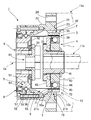
- FIG. 2 is a schematic vertical sectional view thereof.
- the unit type wave gear device 1 (hereinafter, simply referred to as “wave gear device 1”) includes a rigid internal gear 2, a flexible external gear 3, a wave generator 4, and an internal gear 2. It also includes a cross roller bearing 5 that supports the external gear 3 in a relatively rotatable state, and an output shaft 6 that outputs deceleration rotation.
- the internal gear 2 includes an annular gear body portion 21 having a rectangular cross section, and a housing portion 22 projecting from the gear body portion 21 in an annular direction in the direction along the central axis 1a.
- Internal teeth 23 are formed on the circular inner peripheral surface of the gear body portion 21.
- Bolt holes 24 are formed at predetermined angular intervals in the circumferential direction on the outer peripheral side portion of the gear body portion 21.
- the internal gear 2 is fastened and fixed to the motor flange 11a, for example, as shown by an imaginary line.
- the external gear 3 has a cup shape, and has a cylindrical body portion 31 that can be bent in the radial direction and a disk shape that extends inward in the radial direction from the inner end that is one end of the cylindrical body portion 31. It includes a diaphragm 32 and a rigid disk-shaped boss 33 integrally formed on the inner peripheral edge of the diaphragm. External teeth 35 are formed on the outer peripheral surface portion on the side of the opening end 34, which is the other end of the cylindrical body portion 31. The external teeth 35 are formed at positions facing the internal teeth 23 of the internal gear 2 and can mesh with the internal teeth 23. Grease (not shown) is applied or filled as a lubricant in the meshing portion 7 between the internal teeth 23 of the internal gear 2 and the external teeth 35 of the external gear 3.
- the wave generator 4 includes a cylindrical hub 41 connected to an input rotating shaft such as a motor shaft 11b shown by an imaginary line, and a rigid cam plate 43 mounted on the outer peripheral surface of the hub 41 via an oldham joint 42. And a wave bearing 45 mounted on the elliptical outer peripheral surface 44 of the cam plate 43.
- the cam plate 43 is rotatably mounted inside the portion of the cylindrical body 31 of the external gear 3 in which the external teeth 35 are formed via the wave bearing 45, and the formed portion of the external teeth 35 is formed. It is bent into an elliptical shape.
- the external teeth 35 of the external tooth gear 3 bent into an elliptical shape mesh with the internal teeth 23 at both ends of the elliptical shape in the major axis direction and in the vicinity thereof.
- the cross roller bearing 5 can be rolled into an inner ring 51 integrally formed with the output shaft 6, a split outer ring 52, a raceway groove 53 having a rectangular cross section formed between them, and a raceway groove 53. It includes a plurality of rollers 54 that are inserted in the state.
- the outer ring 52 is coaxially fixed to the housing portion 22 of the internal gear 2 by a fastening bolt 55.
- An annular gaps 56 and 57 are formed on both sides of the raceway groove 53 between the inner ring 51 and the outer ring 52.
- the outer annular gap 57 is sealed by an oil seal 9 so that lubricant or the like does not leak to the outside of the unit.
- the bearing for supporting the internal gear 2 and the external gear 3 in a relatively rotatable state is not limited to the cross roller bearing 5. Of course, bearings such as ball bearings may be used.
- the output shaft 6 on which the inner ring 51 is integrally formed is coaxially fixed to the boss 33 of the external gear 3.
- the boss 33 and the output side member are coaxially fastened and fixed by sandwiching the output shaft 6 by the fastening mechanism 61.
- the external gear 3 is provided so that a portion other than the external teeth 35 of the external gear 3 flexed in the radial direction by the wave generator 4 does not interfere with the internal gear 2 and the cross roller bearing 5.
- a gap 8 is formed so as to surround the outer peripheral side.
- the gap 8 is formed along the outer peripheral surface of the cylindrical body portion 31 of the external gear 3.
- a gap 8 is formed between the cylindrical body portion 31 and the housing portion 22 integrally formed with the internal gear 2 surrounding the cylindrical body portion 31.
- One end of the gap 8 in the direction of the central axis 1a communicates with the inner end 71 on the diaphragm side of the meshing portion 7.
- the other end of the gap 8 communicates with the raceway groove 53 via an inner annular gap 56 between the inner ring 51 and the outer ring 52 of the cross roller bearing 5.
- the gear body portion 21 of the internal gear 2 is formed with a through hole 10 for grease flow that extends through the gear body portion 21 in the direction along the central axis 1a.
- the through hole 10 has an inner opening end 10a communicating with the gap 8 and an outer opening end 10b opening in the unit outer space 12 where the outer end portion 72 on the side of the opening end 34 in the meshing portion 7 is exposed.
- the inner opening end 10a is open to the inner end face portion 21a facing the gap 8 in the gear body portion 21.
- the outer open end 10b is open to the opposite outer end face portion 21b of the gear body portion 21. Therefore, the meshing portion 7 is located between the inner end face portion 21a and the outer end face portion 21b.
- the operation of the strain wave gearing device 1 having this configuration will be described.
- the wave generator 4 is rotationally driven by a motor or the like (not shown). Due to the rotation of the wave generator 4, the meshing position of the external gear 3 and the internal gear 2 moves in the circumferential direction, and the relative rotation according to the difference in the number of teeth of these gears is between the gears 2 and 3. appear. For example, the internal gear 2 is fixed, and the deceleration rotation is taken out from the external gear 3 via the output shaft 6.
- the gap 8 communicates with the unit outer space 12 through the through hole 10 formed in the internal gear 2. A part of the grease flowing through the gap 8 goes to the track groove 53, but the rest flows out to the unit outer space 12 through the through hole 10.
- the unit outer space 12 is formed between, for example, the strain wave gearing device 1 and the motor flange 11a, and the outer end portion 72 of the meshing portion 7 is exposed in the unit outer space 12. The grease leaked into the unit outer space 12 returns from the outer end portion 72 to the meshing portion 7.
- the above embodiment is an example in which the present invention is applied to a strain wave gearing equipped with a cup-shaped external gear.
- the present invention is similarly applicable to a unit-type strain wave gearing equipped with a top hat-shaped external gear.
- a through hole for flowing grease is formed in the internal gear. A part of the grease extruded from the meshing portion of the external gear and the internal gear flows out to the side of the predetermined unit outer space through the through hole. As a result, it is possible to prevent or suppress grease from leaking to the outside of the unit from the oil seal attached to the bearing that holds the external gear and the internal gear in a relative rotatable state.
Priority Applications (7)
| Application Number | Priority Date | Filing Date | Title |
|---|---|---|---|
| JP2021540613A JPWO2021033319A1 (zh) | 2019-08-22 | 2019-08-22 | |
| EP19941856.7A EP4019806A4 (en) | 2019-08-22 | 2019-08-22 | ONE SHAFT GEAR DEVICE |
| CN201980099457.3A CN114245852A (zh) | 2019-08-22 | 2019-08-22 | 单元式的波动齿轮装置 |
| US17/619,910 US20220364635A1 (en) | 2019-08-22 | 2019-08-22 | Unit-type strain wave gearing |
| KR1020227000943A KR20220019284A (ko) | 2019-08-22 | 2019-08-22 | 유닛타입의 파동기어장치 |
| PCT/JP2019/032887 WO2021033319A1 (ja) | 2019-08-22 | 2019-08-22 | ユニットタイプの波動歯車装置 |
| TW109112593A TW202108913A (zh) | 2019-08-22 | 2020-04-15 | 單位型的諧波齒輪裝置 |
Applications Claiming Priority (1)
| Application Number | Priority Date | Filing Date | Title |
|---|---|---|---|
| PCT/JP2019/032887 WO2021033319A1 (ja) | 2019-08-22 | 2019-08-22 | ユニットタイプの波動歯車装置 |
Publications (1)
| Publication Number | Publication Date |
|---|---|
| WO2021033319A1 true WO2021033319A1 (ja) | 2021-02-25 |
Family
ID=74660471
Family Applications (1)
| Application Number | Title | Priority Date | Filing Date |
|---|---|---|---|
| PCT/JP2019/032887 WO2021033319A1 (ja) | 2019-08-22 | 2019-08-22 | ユニットタイプの波動歯車装置 |
Country Status (7)
| Country | Link |
|---|---|
| US (1) | US20220364635A1 (zh) |
| EP (1) | EP4019806A4 (zh) |
| JP (1) | JPWO2021033319A1 (zh) |
| KR (1) | KR20220019284A (zh) |
| CN (1) | CN114245852A (zh) |
| TW (1) | TW202108913A (zh) |
| WO (1) | WO2021033319A1 (zh) |
Citations (6)
| Publication number | Priority date | Publication date | Assignee | Title |
|---|---|---|---|---|
| US3482770A (en) * | 1968-04-10 | 1969-12-09 | Laval Separator Co De | Variable speed power transmission |
| JP4877804B2 (ja) | 2007-03-08 | 2012-02-15 | 株式会社ハーモニック・ドライブ・システムズ | 波動歯車減速機の潤滑方法および回転テーブル装置 |
| JP3187367U (ja) * | 2013-09-11 | 2013-11-21 | 株式会社ハーモニック・ドライブ・システムズ | カップ型波動歯車装置ユニット |
| WO2014091522A1 (ja) | 2012-12-12 | 2014-06-19 | 株式会社ハーモニック・ドライブ・システムズ | 入力軸受け付き波動歯車ユニット |
| WO2014203293A1 (ja) | 2013-06-20 | 2014-12-24 | 株式会社ハーモニック・ドライブ・システムズ | 中空型波動歯車ユニット |
| JP2018168956A (ja) * | 2017-03-30 | 2018-11-01 | セイコーエプソン株式会社 | ロボットおよび歯車ユニット |
Family Cites Families (15)
| Publication number | Priority date | Publication date | Assignee | Title |
|---|---|---|---|---|
| US3604287A (en) * | 1969-08-05 | 1971-09-14 | Usm Corp | Modified harmonic-drive actuators |
| JPH07116183B2 (ja) | 1987-03-31 | 1995-12-13 | 三菱化学株式会社 | チアジアゾ−ル誘導体及びこれを有効成分とする殺虫殺ダニ剤 |
| JPH0953707A (ja) * | 1995-08-16 | 1997-02-25 | Harmonic Drive Syst Ind Co Ltd | 波動歯車装置のグリス供給機構 |
| US5984048A (en) * | 1997-09-10 | 1999-11-16 | Harmonic Drive Systems, Inc. | Lubricant supplying mechanism for a wave gear drive |
| SE9802116D0 (sv) * | 1998-06-15 | 1998-06-15 | Alfa Laval Ab | Dekantercentrifug |
| JP2000120811A (ja) * | 1998-08-12 | 2000-04-28 | Teijin Seiki Co Ltd | 撓み噛み合い式減速機 |
| US6026711A (en) * | 1998-09-10 | 2000-02-22 | Harmonic Drive Technologies | Harmonic drive bearing arrangement |
| JP2002339990A (ja) * | 2001-05-22 | 2002-11-27 | Harmonic Drive Syst Ind Co Ltd | 軽量ベアリングおよび波動歯車装置 |
| JP6180417B2 (ja) | 2011-09-15 | 2017-08-16 | タイペイ メディカル ユニバーシティ | 心不全またはニューロン損傷の治療剤製造のための化合物の使用 |
| CN104040218B (zh) * | 2013-01-09 | 2016-10-26 | 谐波传动系统有限公司 | 波动齿轮装置 |
| JP2014203293A (ja) | 2013-04-05 | 2014-10-27 | 株式会社日立製作所 | 開発支援システム、開発支援方法、および開発支援プログラム |
| WO2014203295A1 (ja) * | 2013-06-20 | 2014-12-24 | 株式会社ハーモニック・ドライブ・システムズ | 軸受ホルダー、軸受機構および波動歯車装置 |
| KR102379849B1 (ko) * | 2017-02-28 | 2022-03-28 | 하모닉 드라이드 아게 | 내부 시일을 갖는 스트레인 웨이브 기어 기구 |
| JP2019199893A (ja) * | 2018-05-14 | 2019-11-21 | セイコーエプソン株式会社 | ロボット、歯車装置および歯車装置ユニット |
| US10801608B2 (en) * | 2018-10-31 | 2020-10-13 | Hiwin Technologies Corp. | Harmonic reducer with an oil guiding ring |
-
2019
- 2019-08-22 JP JP2021540613A patent/JPWO2021033319A1/ja active Pending
- 2019-08-22 EP EP19941856.7A patent/EP4019806A4/en not_active Withdrawn
- 2019-08-22 KR KR1020227000943A patent/KR20220019284A/ko not_active Application Discontinuation
- 2019-08-22 US US17/619,910 patent/US20220364635A1/en not_active Abandoned
- 2019-08-22 CN CN201980099457.3A patent/CN114245852A/zh active Pending
- 2019-08-22 WO PCT/JP2019/032887 patent/WO2021033319A1/ja unknown
-
2020
- 2020-04-15 TW TW109112593A patent/TW202108913A/zh unknown
Patent Citations (6)
| Publication number | Priority date | Publication date | Assignee | Title |
|---|---|---|---|---|
| US3482770A (en) * | 1968-04-10 | 1969-12-09 | Laval Separator Co De | Variable speed power transmission |
| JP4877804B2 (ja) | 2007-03-08 | 2012-02-15 | 株式会社ハーモニック・ドライブ・システムズ | 波動歯車減速機の潤滑方法および回転テーブル装置 |
| WO2014091522A1 (ja) | 2012-12-12 | 2014-06-19 | 株式会社ハーモニック・ドライブ・システムズ | 入力軸受け付き波動歯車ユニット |
| WO2014203293A1 (ja) | 2013-06-20 | 2014-12-24 | 株式会社ハーモニック・ドライブ・システムズ | 中空型波動歯車ユニット |
| JP3187367U (ja) * | 2013-09-11 | 2013-11-21 | 株式会社ハーモニック・ドライブ・システムズ | カップ型波動歯車装置ユニット |
| JP2018168956A (ja) * | 2017-03-30 | 2018-11-01 | セイコーエプソン株式会社 | ロボットおよび歯車ユニット |
Non-Patent Citations (1)
| Title |
|---|
| See also references of EP4019806A4 |
Also Published As
| Publication number | Publication date |
|---|---|
| EP4019806A4 (en) | 2023-04-19 |
| JPWO2021033319A1 (zh) | 2021-02-25 |
| EP4019806A1 (en) | 2022-06-29 |
| CN114245852A (zh) | 2022-03-25 |
| TW202108913A (zh) | 2021-03-01 |
| US20220364635A1 (en) | 2022-11-17 |
| KR20220019284A (ko) | 2022-02-16 |
Similar Documents
| Publication | Publication Date | Title |
|---|---|---|
| TWI609141B (zh) | Hollow harmonic gear unit | |
| KR101757154B1 (ko) | 중공 파동기어장치 및 중공 액추에이터 | |
| JP7032011B2 (ja) | ユニットタイプの波動歯車装置 | |
| TWI609142B (zh) | Harmonic gear device | |
| JP6909141B2 (ja) | 撓み噛合い式歯車装置 | |
| CN111164333B (zh) | 挠曲啮合式齿轮装置 | |
| JP7340937B2 (ja) | 減速装置 | |
| TWI770208B (zh) | 具備潤滑劑混合防止部的諧波齒輪裝置 | |
| TW201805548A (zh) | 齒輪裝置 | |
| KR20190092262A (ko) | 휨맞물림식 기어장치 | |
| WO2021033319A1 (ja) | ユニットタイプの波動歯車装置 | |
| JP5064272B2 (ja) | ユニット型歯車装置のグリース漏れ防止構造 | |
| JP4646831B2 (ja) | 減速機 | |
| JP7227815B2 (ja) | 動力伝達装置 | |
| JP5143718B2 (ja) | 回転装置 | |
| CN113357317A (zh) | 挠曲啮合式齿轮装置 | |
| JP2022526190A (ja) | 波動歯車装置 | |
| JP7253089B2 (ja) | 撓み噛合い式歯車装置 | |
| JP2022038565A (ja) | 撓み噛合い式歯車装置 | |
| JP2022536629A (ja) | 波動歯車装置 | |
| JP2015045392A (ja) | 変速装置 |
Legal Events
| Date | Code | Title | Description |
|---|---|---|---|
| 121 | Ep: the epo has been informed by wipo that ep was designated in this application |
Ref document number: 19941856 Country of ref document: EP Kind code of ref document: A1 |
|
| ENP | Entry into the national phase |
Ref document number: 2021540613 Country of ref document: JP Kind code of ref document: A |
|
| ENP | Entry into the national phase |
Ref document number: 20227000943 Country of ref document: KR Kind code of ref document: A |
|
| NENP | Non-entry into the national phase |
Ref country code: DE |
|
| ENP | Entry into the national phase |
Ref document number: 2019941856 Country of ref document: EP Effective date: 20220322 |