WO2021028972A1 - 電力変換装置の制御回路 - Google Patents
電力変換装置の制御回路 Download PDFInfo
- Publication number
- WO2021028972A1 WO2021028972A1 PCT/JP2019/031654 JP2019031654W WO2021028972A1 WO 2021028972 A1 WO2021028972 A1 WO 2021028972A1 JP 2019031654 W JP2019031654 W JP 2019031654W WO 2021028972 A1 WO2021028972 A1 WO 2021028972A1
- Authority
- WO
- WIPO (PCT)
- Prior art keywords
- current
- voltage
- inductor
- control circuit
- circuit
- Prior art date
Links
- 238000006243 chemical reaction Methods 0.000 title claims abstract description 24
- 238000001514 detection method Methods 0.000 claims abstract description 70
- 238000000034 method Methods 0.000 claims description 12
- 238000010586 diagram Methods 0.000 description 32
- 230000004048 modification Effects 0.000 description 12
- 238000012986 modification Methods 0.000 description 12
- 239000003990 capacitor Substances 0.000 description 7
- 238000009499 grossing Methods 0.000 description 6
- 230000007274 generation of a signal involved in cell-cell signaling Effects 0.000 description 5
- 230000007246 mechanism Effects 0.000 description 3
- 230000001360 synchronised effect Effects 0.000 description 3
- 230000003321 amplification Effects 0.000 description 2
- 238000009795 derivation Methods 0.000 description 2
- 230000000694 effects Effects 0.000 description 2
- 238000003199 nucleic acid amplification method Methods 0.000 description 2
- 230000008901 benefit Effects 0.000 description 1
- 230000006866 deterioration Effects 0.000 description 1
- 239000000696 magnetic material Substances 0.000 description 1
- 230000002265 prevention Effects 0.000 description 1
- 230000008569 process Effects 0.000 description 1
- 230000004044 response Effects 0.000 description 1
Images


Classifications
-
- H—ELECTRICITY
- H02—GENERATION; CONVERSION OR DISTRIBUTION OF ELECTRIC POWER
- H02M—APPARATUS FOR CONVERSION BETWEEN AC AND AC, BETWEEN AC AND DC, OR BETWEEN DC AND DC, AND FOR USE WITH MAINS OR SIMILAR POWER SUPPLY SYSTEMS; CONVERSION OF DC OR AC INPUT POWER INTO SURGE OUTPUT POWER; CONTROL OR REGULATION THEREOF
- H02M1/00—Details of apparatus for conversion
- H02M1/42—Circuits or arrangements for compensating for or adjusting power factor in converters or inverters
- H02M1/4208—Arrangements for improving power factor of AC input
- H02M1/4225—Arrangements for improving power factor of AC input using a non-isolated boost converter
-
- H—ELECTRICITY
- H02—GENERATION; CONVERSION OR DISTRIBUTION OF ELECTRIC POWER
- H02M—APPARATUS FOR CONVERSION BETWEEN AC AND AC, BETWEEN AC AND DC, OR BETWEEN DC AND DC, AND FOR USE WITH MAINS OR SIMILAR POWER SUPPLY SYSTEMS; CONVERSION OF DC OR AC INPUT POWER INTO SURGE OUTPUT POWER; CONTROL OR REGULATION THEREOF
- H02M1/00—Details of apparatus for conversion
- H02M1/42—Circuits or arrangements for compensating for or adjusting power factor in converters or inverters
- H02M1/4208—Arrangements for improving power factor of AC input
-
- H—ELECTRICITY
- H02—GENERATION; CONVERSION OR DISTRIBUTION OF ELECTRIC POWER
- H02M—APPARATUS FOR CONVERSION BETWEEN AC AND AC, BETWEEN AC AND DC, OR BETWEEN DC AND DC, AND FOR USE WITH MAINS OR SIMILAR POWER SUPPLY SYSTEMS; CONVERSION OF DC OR AC INPUT POWER INTO SURGE OUTPUT POWER; CONTROL OR REGULATION THEREOF
- H02M1/00—Details of apparatus for conversion
- H02M1/0003—Details of control, feedback or regulation circuits
- H02M1/0009—Devices or circuits for detecting current in a converter
-
- H—ELECTRICITY
- H02—GENERATION; CONVERSION OR DISTRIBUTION OF ELECTRIC POWER
- H02M—APPARATUS FOR CONVERSION BETWEEN AC AND AC, BETWEEN AC AND DC, OR BETWEEN DC AND DC, AND FOR USE WITH MAINS OR SIMILAR POWER SUPPLY SYSTEMS; CONVERSION OF DC OR AC INPUT POWER INTO SURGE OUTPUT POWER; CONTROL OR REGULATION THEREOF
- H02M1/00—Details of apparatus for conversion
- H02M1/0003—Details of control, feedback or regulation circuits
- H02M1/0025—Arrangements for modifying reference values, feedback values or error values in the control loop of a converter
-
- H—ELECTRICITY
- H02—GENERATION; CONVERSION OR DISTRIBUTION OF ELECTRIC POWER
- H02M—APPARATUS FOR CONVERSION BETWEEN AC AND AC, BETWEEN AC AND DC, OR BETWEEN DC AND DC, AND FOR USE WITH MAINS OR SIMILAR POWER SUPPLY SYSTEMS; CONVERSION OF DC OR AC INPUT POWER INTO SURGE OUTPUT POWER; CONTROL OR REGULATION THEREOF
- H02M1/00—Details of apparatus for conversion
- H02M1/0048—Circuits or arrangements for reducing losses
- H02M1/0054—Transistor switching losses
- H02M1/0058—Transistor switching losses by employing soft switching techniques, i.e. commutation of transistors when applied voltage is zero or when current flow is zero
-
- H—ELECTRICITY
- H02—GENERATION; CONVERSION OR DISTRIBUTION OF ELECTRIC POWER
- H02M—APPARATUS FOR CONVERSION BETWEEN AC AND AC, BETWEEN AC AND DC, OR BETWEEN DC AND DC, AND FOR USE WITH MAINS OR SIMILAR POWER SUPPLY SYSTEMS; CONVERSION OF DC OR AC INPUT POWER INTO SURGE OUTPUT POWER; CONTROL OR REGULATION THEREOF
- H02M1/00—Details of apparatus for conversion
- H02M1/42—Circuits or arrangements for compensating for or adjusting power factor in converters or inverters
- H02M1/4208—Arrangements for improving power factor of AC input
- H02M1/4233—Arrangements for improving power factor of AC input using a bridge converter comprising active switches
-
- H—ELECTRICITY
- H02—GENERATION; CONVERSION OR DISTRIBUTION OF ELECTRIC POWER
- H02M—APPARATUS FOR CONVERSION BETWEEN AC AND AC, BETWEEN AC AND DC, OR BETWEEN DC AND DC, AND FOR USE WITH MAINS OR SIMILAR POWER SUPPLY SYSTEMS; CONVERSION OF DC OR AC INPUT POWER INTO SURGE OUTPUT POWER; CONTROL OR REGULATION THEREOF
- H02M7/00—Conversion of ac power input into dc power output; Conversion of dc power input into ac power output
- H02M7/02—Conversion of ac power input into dc power output without possibility of reversal
- H02M7/04—Conversion of ac power input into dc power output without possibility of reversal by static converters
- H02M7/12—Conversion of ac power input into dc power output without possibility of reversal by static converters using discharge tubes with control electrode or semiconductor devices with control electrode
- H02M7/21—Conversion of ac power input into dc power output without possibility of reversal by static converters using discharge tubes with control electrode or semiconductor devices with control electrode using devices of a triode or transistor type requiring continuous application of a control signal
- H02M7/217—Conversion of ac power input into dc power output without possibility of reversal by static converters using discharge tubes with control electrode or semiconductor devices with control electrode using devices of a triode or transistor type requiring continuous application of a control signal using semiconductor devices only
- H02M7/219—Conversion of ac power input into dc power output without possibility of reversal by static converters using discharge tubes with control electrode or semiconductor devices with control electrode using devices of a triode or transistor type requiring continuous application of a control signal using semiconductor devices only in a bridge configuration
-
- H—ELECTRICITY
- H02—GENERATION; CONVERSION OR DISTRIBUTION OF ELECTRIC POWER
- H02M—APPARATUS FOR CONVERSION BETWEEN AC AND AC, BETWEEN AC AND DC, OR BETWEEN DC AND DC, AND FOR USE WITH MAINS OR SIMILAR POWER SUPPLY SYSTEMS; CONVERSION OF DC OR AC INPUT POWER INTO SURGE OUTPUT POWER; CONTROL OR REGULATION THEREOF
- H02M1/00—Details of apparatus for conversion
- H02M1/0003—Details of control, feedback or regulation circuits
- H02M1/0012—Control circuits using digital or numerical techniques
Definitions
- the present invention relates to a control circuit of a power conversion device such as a power factor improving circuit, and the power conversion device.
- a power factor improving circuit (hereinafter referred to as a PFC circuit) that operates in the current critical mode, it is necessary to turn on the switching element after the inductor current becomes 0. Therefore, it is necessary to accurately detect the zero point of the inductor current (see, for example, Non-Patent Document 1).
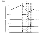
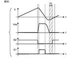
- FIG. 2 is a timing chart for explaining the delay of zero detection of the inductor current iL in the current detection circuit in the conventional example.
- Td in FIG. 2 shows the delay time of zero detection due to the delay by the operational amplifier and the noise filter. That is, due to the delay of the comparator IC and the time constant of the noise filter, the comparator starts up with a delay from the ideal current zero detection point, so that the negative current increases as shown in FIG.
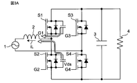
- FIG. 3A is a circuit diagram of a switching power supply device for explaining the mechanism by which the loss of the switching power supply device increases due to the delay of zero detection of the inductor current
- FIG. 3B is a timing chart showing the operation of the switching power supply device of FIG. 3A.
- the switching power supply device includes an AC power supply 1, an inductor 2, switching elements S1 to S4, a smoothing capacitor 3, and a load resistor 4.
- FIG. 3B shows an inductor current iL, a drain-source voltage Vds of the switching element S2, a drive signal G2 for the switching element S2, and a drive signal G1 for the switching element S1.
- T1 indicates a period during which soft switching is performed by the negative current of the inductor current iL.
- An object of the present invention is to solve the above problems, and in a PFC circuit operating in a current critical mode, a control circuit of a power converter capable of accurately detecting the zero point of the inductor current as compared with the prior art. And to provide the power conversion device.
- the control circuit of the power conversion device is A control circuit for a power converter that includes an inductor and a PFC circuit that operates in current critical mode.
- a first unit that detects the current of the inductor or the current corresponding to the current of the inductor or includes the current of the inductor, amplifies the voltage corresponding to the detected current with a predetermined gain, and then outputs the voltage as the detection voltage.
- a comparator that compares the detected voltage with a predetermined reference voltage and outputs a comparison result signal
- a second detection circuit that detects the input voltage of the power converter, and It is provided with a third detection circuit that detects the output voltage of the power converter.
- the control circuit has the detected input voltage, the detected output voltage V, a preset delay time, an inductance value of the inductor, and a conversion coefficient when converting a current detected by the first detection circuit into a voltage. Based on the power supply voltage and the gain of the gain, the reference voltage for detecting the zero value of the current of the inductor is calculated and output to the comparator. And.
- the present invention in the PFC circuit operating in the current critical mode, it is possible to prevent the detection delay of the inductor current and accurately detect the zero point of the inductor current as compared with the prior art. This reduces the loss of the power converter and leads to a higher density of the power supply device.
- FIG. 1A is a circuit diagram showing a configuration example of a switching power supply device including the control circuit 20 according to the embodiment.
- the switching power supply device includes an AC power supply 1, a reactor 2 inductor, bridge-connected switching elements S1 to S4, a smoothing capacitor 3, a load resistor 4, and a shunt resistor. It includes Rs and a control circuit 20.
- the control circuit 20 includes a controller 10, a current detection unit 5, a drive signal generation circuit 11, an input voltage detection circuit 12, and an output voltage detection circuit 13.
- the input voltage Vin generated by the AC power supply 1 is input to the bridge connection circuit of the switching elements S1 to S4 via the shunt resistor Rs and the inductor 2.
- the switching elements S1 to S4 are turned on / off by the drive signals G1 to G4 from the drive signal generation circuit 11, and after the input voltage Vin is switched, the smoothed direct current is passed through the smoothing capacitor 3.
- the voltage is output to the load resistor 4 as the output voltage Vout.
- the shunt resistor Rs converts the inductor current iL into a voltage value and outputs it to the current detection unit 5.
- the input voltage detection circuit 12 detects the input voltage Vin and outputs it to the controller 10, and the output voltage detection circuit 13 detects the output voltage Vout and outputs it to the controller 10.
- the controller 10 controls the drive signal generation circuit 11 so as to generate the drive signals G1 to G4 in the current critical mode, for example, based on each input signal.
- the controller 10 includes a DA converter 10a that generates a reference voltage Vref determined in advance by a method described in detail later.
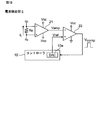
- FIG. 1B is a circuit diagram showing a configuration example of the current detection unit 5 of FIG. 1A.
- the current detection unit 5 includes an operational amplifier 21 and a comparator 22.
- Vcc is the power supply voltage.
- the operational amplifier 21 amplifies the voltage corresponding to the inductor current iL detected by the shunt resistor Rs, and outputs the amplified voltage Vamp to the comparator 22.
- the comparator 22 compares the input amplification voltage Vamp with the reference voltage Vref from the DA converter 10a in the controller 10, generates a comparison result voltage Vcomp, and outputs the comparison result voltage Vcomp to the controller 10.
- the controller 10 detects the zero current of the inductor current iL based on the comparison result voltage Vcomp, and based on this, for example, performs a switching operation in the current critical mode to generate drive signals G1 to G4.
- the drive signal generation circuit 11 is controlled so as to generate the current.
- the polarity of the reference voltage Vref is inverted according to the input voltage Vin (FIG. 1A) to the PFC circuit, that is, according to the direction of the inductor current iL.
- the detection delay can be prevented by changing the reference voltage Vref of the comparator 22 according to the delay time.
- Vref the reference voltage
- FIG. 4A is a circuit diagram showing a configuration example of the current detection unit according to the conventional example
- FIG. 4B is a timing chart showing the operation of the current detection unit of FIG. 4A.
- the reference voltage Vref of the comparator 22 is a constant voltage such as Vcc / 2
- a delay time Tdelay occurs as shown in FIG. 4B.
- FIG. 4C is a circuit diagram showing a configuration example of the current detection unit 5 according to the embodiment
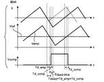
- FIG. 4D is a timing chart showing the operation of the current detection unit 5 of FIG. 4C.
- the reference voltage Vref is raised from the DA converter 10a of the controller 10 according to the delay time. That is, in a PFC circuit in which the input voltage is alternating current, the delay time Tdelay can be reduced by changing the reference voltage Vref depending on the input voltage Vin, as shown in FIG. 4D, as compared with FIG. 4B. it can.
- Td_amp is the delay time due to the amplification operation of the operational amplifier 21.
- Td_comp is the delay time due to the comparison operation of the comparator 22.
- Tdead-time is the dead time of the switching elements S1 and S2.
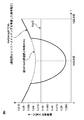
- FIG. 5 is a graph showing the operation of the current detection unit 5 according to the embodiment.
- Vref half cycle of the input voltage Vin
- Tdelay 50ns
- Vin (rms) 200V
- f LINE 50Hz
- FIG. 6 is a block diagram showing a configuration example of a power conversion device using the PFC circuit according to the embodiment.
- the power conversion device includes an AC power supply 1, a PFC circuit 100, a DC / DC converter 101, and a load 102. Since the control target is a PFC circuit, the input AC voltage and the output DC voltage are Vin (t) and Vout, respectively.
- the input voltage Vin is expressed by the following equation.
- the resistance value of the shunt resistor Rs is Rs
- the gain of the operational amplifier 21 is G
- the voltage applied to the operational amplifier 21 and the comparator 22 is Vcc.
- FIG. 7 is a waveform diagram for explaining a method of deriving the reference voltage Vref used in the current detection unit 5 according to the embodiment.
- the inductor current iL in the half cycle of the input voltage Vin is as shown in the graph of FIG. 7, and an enlarged view of one switching cycle is shown on the right side.
- the slope of the inductor current iL is obtained from win (t), Vout, and the inductance value L.
- the current fluctuation amount ⁇ idelay that changes during the delay time is expressed by the following equation.
- FIG. 8A and 8B are waveform diagrams for explaining soft switching of the PFC circuit by the current detection unit 5 according to the embodiment.
- FIG. 8A is a waveform diagram when Vin> Vout / 2
- FIG. 8B is a waveform diagram when additional on-time control is performed.
- the present embodiment is characterized in that TCM control is performed only by changing the reference voltage Vref of the comparator 22 by using a known TCM (Triangular Current Mode) control method.
- TCM Triangular Current Mode
- Vin Input voltage
- Vds Drain-source voltage of main switch element
- iL Inductor current
- Vgs Gate-source voltage of main switch element
- the controller 10 detects the detected input voltage Vin and output voltage Vout, the preset delay time, the inductance value of the inductor 2, and the resistance value of the shunt resistance Rs (in the modification described later, when the current is detected). It is a conversion coefficient when converting the inductor current iL into a voltage, and is generally the conversion coefficient.)
- the reference voltage Vref for making the delay of is substantially zero is calculated and output to the comparator 22.
- the synchronous rectifier switch element is kept on for a predetermined additional time ⁇ [ns] from the current zero detection point to flow a negative current for extracting the electric charge.
- the soft switching method shown in FIGS. 8A and 8B allows a negative current required for soft switching to flow by continuously turning on + ⁇ [ns] and giving an additional on time.
- the negative current required for soft switching can be adjusted to flow by changing the reference voltage Vref.
- FIG. 9 is a waveform diagram for explaining a method of deriving the reference voltage Vref used in the current detection unit 5 according to the modified example.
- the reference voltage Vref only for the delay prevention control of FIG. 5 is lowered for a predetermined time period, for example, in an elliptical shape.
- the negative current required for soft switching can be obtained from the input voltage Vin, the output voltage Vout, and the inductor tans L of the inductor 2, and can be realized by adding it to the reference voltage Vref in consideration of the delay time.
- FIG. 10A is a block diagram showing a configuration example of the switching power supply device according to the first modification.
- the inductor current iL flowing through the shunt resistor Rs is detected, but the present invention is not limited to this, and as shown in FIG. 10A, for example, CT (Current Transformer), Hall element, GMR (Giant Magneto). Resistive effect)
- CT Current Transformer
- Hall element Hall element
- GMR Giant Magneto
- Resistive effect The inductor current iL may be detected by using a current sensor 14 such as an element.
- FIG. 10B is a block diagram showing a configuration example of the switching power supply device according to the second modification.
- a shunt resistor Rs1 may be inserted between the ground side of the switching elements S2 and S4 and the load resistor 4, and the zero point of the inductor current iL may be detected.
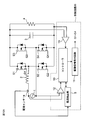
- FIG. 11A is a block diagram showing a configuration example of the switching power supply device according to the third modification.
- FIG. 11A shows an example of a synchronous rectification type step-up PFC circuit.
- the switching power supply device includes an AC power supply 1, four bridge-connected diodes D1 to D4, a reactor inductor 2, switching elements S11 and S12, a shunt resistor Rs2, and a smoothing capacitor 3.
- a load resistor 4 is provided.
- a shunt resistor Rs2 for detecting the zero point of the inductor current iL is inserted between the switching element S12 and the smoothing capacitor 3. It is preferable to do so.
- FIG. 11B is a block diagram showing a configuration example of the switching power supply device according to the modified example 4.
- a shunt resistor Rs3 for detecting the zero point of the inductor current iL may be inserted between the diodes D1 and D4 and the inductor 2.
- the current corresponding to the inductor current iL or the current including the inductor current iL is detected.
- FIG. 12 is a circuit diagram showing a modified example of the current detection unit 5 of FIG. 1B.
- a controller 10A having a DA converter 10a, a comparator 22 and a signal processing unit 10b is provided.
- the signal processing unit 10b performs signal processing for changing the above-mentioned reference voltage Vref based on the comparison result signal Vcomp from the comparator 22.
- Some controllers such as DSPs (digital signal processors) have a built-in comparator function as well as AD converters and DA converters. By using the built-in comparator 22, there is an advantage that an external comparator IC becomes unnecessary.
- the inductor current detection delay is prevented and the inductor is more accurately compared with the prior art.
- the zero point of the current can be detected accurately. This reduces the loss of the power converter and leads to a higher density of the power supply device. In particular, since no magnetic material is used, the loss does not increase even when driven at high frequencies, and no additional parts are required. Further, by applying the method of changing the reference voltage Vref, a soft switching function using voltage resonance can be easily implemented.
- switching power supply device is described in the above embodiments or modifications, the present invention is not limited to this, and can be applied to various power conversion devices including the switching power supply device.
- the detection delay of the inductor current is prevented, and the zero point of the inductor current is accurately detected as compared with the prior art. can do. This reduces the loss of the power converter and leads to a higher density of the power supply device.
Abstract
インダクタを含む力率改善回路等の電力変換装置の制御回路が提供される。制御回路は、インダクタの電流を検出し、検出した電流に対応する電圧を所定の利得で増幅した後、検出電圧として出力する第1の検出回路と、検出電圧を所定の基準電圧と比較して比較結果信号を出力する比較器と、電力変換装置の入力電圧を検出する第2の検出回路と、電力変換装置の出力電圧を検出する第3の検出回路とを備える。制御回路は、検出した入力電圧、検出した出力電圧V、予め設定された遅延時間、インダクタのインダクタンス値、第1の検出回路により検出した電流を電圧に変換するときの変換係数、電源電圧、及び利得に基づいて、インダクタの電流のゼロ値を検出するときの遅延を実質的にゼロにするための基準電圧を計算して比較器に出力する。
Description
本発明は、例えば力率改善回路などの電力変換装置の制御回路と、当該電力変換装置とに関する。
例えば電流臨界モードで動作する力率改善回路(以下、PFC回路という。)においては、インダクタ電流が0になってからスイッチング素子をオンする必要がある。従って、インダクタ電流のゼロ点を正確に検出する必要がある(例えば、非特許文献1参照)。
Qingyun Huang et al., "Predictive ZVS Control with Improved ZVS Time Margin and Limited Variable Frequency Range for A 99% Efficient, 130W/in3 MHz GaN Totem-Pole PFC Rectifier," IEEE Transactions on Power Electronics, Vol. 34, No. 7, 2018
従来、当該インダクタ電流の検出回路では、シャント抵抗とオペアンプ、コンパレータを用いて電流検出を行っていた(例えば、非特許文献1参照)。そのため、ICの遅延や、ノイズ除去用のフィルタでの遅延が発生して、正確にゼロ検出を行うことができないという課題があった。
図2は従来例における電流検出回路におけるインダクタ電流iLのゼロ検出の遅延を説明するためのタイミングチャートである。図2において、ゼロ検出用比較結果信号の理想値と現実値を図示している。図2のtdは、オペアンプ及びノイズフィルタによる遅延のためのゼロ検出の遅延時間を示す。すなわち、コンパレータICの遅延やノイズフィルタの時定数により、理想値の電流ゼロ検出点から遅れてコンパレータが立ち上がるため、図2に示すように負電流が増加する。
図3Aは前記インダクタ電流のゼロ検出の遅延によるスイッチング電源装置の損失が増加するメカニズムを説明するためのスイッチング電源装置の回路図であり、図3Bは図3Aのスイッチング電源装置の動作を示すタイミングチャートである。図3Aにおいて、スイッチング電源装置は、交流電源1と、インダクタ2と、スイッチング素子S1~S4と、平滑用キャパシタ3と、負荷抵抗4とを備える。図3Bにおいて、インダクタ電流iLと、スイッチング素子S2のドレイン・ソース間電圧Vdsと、スイッチング素子S2に対する駆動信号G2と、スイッチング素子S1に対する駆動信号G1とを示す。ここで、T1は、インダクタ電流iLの負電流によりソフトスイッチングさせる期間を示す。
前記ソフトスイッチングによる遅延により、図3C及び図3Dに示すように、インダクタ電流iLの負電流はスイッチング素子S2のボディダイオードを流れる。この余分な負電流が流れることで、スイッチング電源装置の損失が増大する。
特に、小型大容量電源の開発過程においては、高周波でかつ大電流の検出を行う必要があり、それに対する解決手段が課題となっていた。
本発明の目的は以上の問題点を解決し、電流臨界モードで動作するPFC回路において、従来技術に比較して正確にインダクタ電流のゼロ点を正確に検出することができる電力変換装置の制御回路及び、当該電力変換装置を提供することにある。
本発明の一態様に係る電力変換装置の制御回路は、
インダクタを含み、電流臨界モードで動作するPFC回路を含む電力変換装置の制御回路であって、
前記インダクタの電流、もしくは前記インダクタの電流に対応し又は前記インダクタの電流を含む電流を検出し、前記検出した電流に対応する電圧を所定の利得で増幅した後、検出電圧として出力する第1の検出回路と、
前記検出電圧を所定の基準電圧と比較して比較結果信号を出力する比較器と、
前記電力変換装置の入力電圧を検出する第2の検出回路と、
前記電力変換装置の出力電圧を検出する第3の検出回路とを備え、
前記制御回路は、前記検出した入力電圧、前記検出した出力電圧V、予め設定された遅延時間、前記インダクタのインダクタンス値、前記第1の検出回路により検出した電流を電圧に変換するときの変換係数、電源電圧、及び前記利得の利得に基づいて、前記インダクタの電流のゼロ値を検出するときの遅延を実質的にゼロにするための基準電圧を計算して前記比較器に出力することを特徴とする。
従って、本発明によれば、電流臨界モードで動作するPFC回路において、インダクタ電流の検出遅延を防止して、従来技術に比較して正確にインダクタ電流のゼロ点を正確に検出することができる。これにより、電力変換装置の損失が低減され、電源装置の高密度化につながる。
以下、本発明にかかる実施形態について図面を参照して説明する。なお、同一又は同様の構成要素については同一の符号を付している。
図1Aは実施形態に係る制御回路20を備えたスイッチング電源装置の構成例を示す回路図である。
図1Aにおいて、本実施形態に係るスイッチング電源装置は、交流電源1と、リアクトルであるインダクタ2と、ブリッジ接続されたスイッチング素子S1~S4と、平滑用キャパシタ3と、負荷抵抗4と、シャント抵抗Rsと、制御回路20とを備える。ここで、制御回路20は、コントローラ10と、電流検出部5と、駆動信号発生回路11と、入力電圧検出回路12と、出力電圧検出回路13とを備える。
交流電源1により発生された入力電圧Vinは、シャント抵抗Rs及びインダクタ2を介して、スイッチング素子S1~S4のブリッジ接続回路に入力される。各スイッチング素子S1~S4は駆動信号発生回路11からの駆動信号G1~G4によりオン/オフ制御されることで、入力電圧Vinがスイッチングされた後、平滑用キャパシタ3を介して、平滑された直流電圧が出力電圧Voutとして負荷抵抗4に出力される。
シャント抵抗Rsはインダクタ電流iLを電圧値に変換して電流検出部5に出力する。入力電圧検出回路12は入力電圧Vinを検出してコントローラ10に出力し、出力電圧検出回路13は出力電圧Voutを検出してコントローラ10に出力する。コントローラ10は、入力される各信号に基づいて、例えば電流臨界モードで駆動信号G1~G4を発生するように駆動信号発生回路11を制御する。なお、コントローラ10は、詳細後述する方法で予め決められる基準電圧Vrefを発生するDA変換器10aを備える。
図1Bは図1Aの電流検出部5の構成例を示す回路図である。図1Bにおいて、電流検出部5は、オペアンプ21と、コンパレータ22とを備えて構成される。なお、Vccは電源電圧である。
オペアンプ21は、シャント抵抗Rsにより検出されたインダクタ電流iLに対応する電圧を増幅し、増幅電圧Vampをコンパレータ22に出力する。コンパレータ22は、入力される増幅電圧Vampを、コントローラ10内のDA変換器10aからの基準電圧Vrefと比較して、比較結果電圧Vcompを発生してコントローラ10に出力する。これに応答して、コントローラ10は、比較結果電圧Vcompに基づいて、インダクタ電流iLのゼロ電流を検出し、これに基づいて、例えば電流臨界モードでのスイッチング動作をさせて駆動信号G1~G4を発生するように駆動信号発生回路11を制御する。なお、基準電圧Vrefの極性は、PFC回路への入力電圧Vin(図1A)に応じて、すなわち、インダクタ電流iLの向きに応じて反転される。
以上のように構成された制御回路20を備えたスイッチング電源装置によれば、コンパレータ22の基準電圧Vrefを遅延時間に応じて変化させることで、検出遅延を防止することができる。これにより、臨界モードPFC回路におけるインダクタ電流iLのゼロ点検出遅延による効率悪化を防止することができる。以下、本実施形態の作用効果について詳述する。
図4Aは従来例に係る電流検出部の構成例を示す回路図であり、図4Bは図4Aの電流検出部の動作を示すタイミングチャートである。図4Aに示すように、コンパレータ22の基準電圧Vrefが例えばVcc/2等の一定電圧では、図4Bに示すように、遅延時間Tdelayが発生する。
図4Cは実施形態に係る電流検出部5の構成例を示す回路図であり、図4Dは図4Cの電流検出部5の動作を示すタイミングチャートである。図4Cに示すように、コントローラ10のDA変換器10aから、基準電圧Vrefを遅延時間に応じて上昇させる。すなわち、入力電圧が交流であるPFC回路において、入力電圧Vinに依存して基準電圧Vrefを変化させることで、図4Dに示すように、図4Bとの比較により、遅延時間Tdelayを減少させることができる。なお、図4Dにおいて、
(1)Td_ampはオペアンプ21の増幅動作による遅延時間であり、
(2)Td_compはコンパレータ22の比較動作による遅延時間であり、
(3)Tdead-timeはスイッチング素子S1,S2のデッドタイムである。
(1)Td_ampはオペアンプ21の増幅動作による遅延時間であり、
(2)Td_compはコンパレータ22の比較動作による遅延時間であり、
(3)Tdead-timeはスイッチング素子S1,S2のデッドタイムである。
図5は実施形態に係る電流検出部5の動作を示すグラフである。図5において、例えば、Vcc=3V,Tdelay=50ns,Vin(rms)=200V,fLINE=50Hzのときの基準電圧Vref(入力電圧Vinの半周期)の一例を図示している。図1B及び図5Cの電流検出部5及び個年と10を用いることで、遅延時間Tdelayから導出された基準電圧Vrefを、電流検出部5のコンパレータ22に帰還して入力することで、遅延時間Tdelayを減少させることができる。
以下、基準電圧Vrefの導出方法の一例について以下に説明する。
図6は実施形態に係るPFC回路を用いた電力変換装置の構成例を示すブロック図である。図6において、電力変換装置は、交流電源1と、PFC回路100と、DC/DCコンバータ101と、負荷102とを備えて構成される。制御対象はPFC回路であるため、入力交流電圧及び出力直流電圧であり、それぞれVin(t)、Voutとする。入力電圧Vinは次式で表される。
ここで、入力電圧Vin(rms)及びライン周波数fLINEは国や地域によって異なり、それらの一例は以下の通りである。
Vin(rms)=100V,200V,230V
fLINE=50Hz、又は60Hz
Vin(rms)=100V,200V,230V
fLINE=50Hz、又は60Hz
図1B及び図4Cの電流検出部5を用いたとき、シャント抵抗Rsの抵抗値をRsとし、オペアンプ21の利得をGとし、オペアンプ21及びコンパレータ22に印加する電圧をVccとする。
図7は実施形態に係る電流検出部5に用いる基準電圧Vrefの導出方法を説明するための波形図である。
入力電圧Vinの半周期におけるインダクタ電流iLは、図7のグラフのようになり、1スイッチンング周期分を抜き出した拡大図を右側に図示する。ここで、インダクタ電流iLの傾きはvin(t)、Vout、インダクタンス値Lにより求められる。電流ゼロの検出遅延時間Tdelayに基づいて、遅延時間中に変化する電流変動量Δidelayは次式で表される。
この電流変動量Δidelayだけ、早く電流ゼロを検出すればよい。当該電流変動量Δidelayに対してシャント抵抗の抵抗値Rs及びオペアンプ21の利得Gを乗算することで電圧に変換できるので、遅延時間を考慮した基準電圧Vrefは次式で表される。
図8A及び図8Bは実施形態に係る電流検出部5によるPFC回路のソフトスイッチングを説明するための波形図である。ここで、図8AはVin>Vout/2のときの波形図であり、図8Bは追加オン時間制御のときの波形図である。
本実施形態では、公知のTCM(Triangular Current Mode)制御方法を用いて、コンパレータ22の基準電圧Vrefを変化させるのみでTCM制御を行うことを特徴としている。図8A及び図8Bにおいて、各符号は以下の通りである。
Vin:入力電圧
Vds:メインスイッチ素子のドレイン・ソース間電圧
iL:インダクタ電流
Vgs:メインスイッチ素子のゲート・ソース間電圧
Vin:入力電圧
Vds:メインスイッチ素子のドレイン・ソース間電圧
iL:インダクタ電流
Vgs:メインスイッチ素子のゲート・ソース間電圧
以上の実施形態では、コントローラ10は、検出した入力電圧Vin及び出力電圧Vout、予め設定された遅延時間、インダクタ2のインダクタンス値、シャント抵抗Rsの抵抗値(後述する変形例では、電流検出時のインダクタ電流iLを電圧に変換するときの変換係数であり、一般的には、当該変換係数である。)、電源電圧Vcc、オペアンプ21の利得に基づいて、インダクタ電流iLのゼロ値を検出するときの遅延を実質的にゼロにするための基準電圧Vrefを計算してコンパレータ22に出力する。これにより、電流臨界モードで動作するPFC回路を備えた電力変換装置において、インダクタ電流の検出遅延を防止して、従来技術に比較して正確にインダクタ電流のゼロ点を正確に検出することができる。
図8AのVin>Vout/2の条件下では、スイッチング素子の電荷を引き抜くための負電流が足りずソフトスイッチングできない。従って、TCM制御方法を用いて、同期整流スイッチ素子を、電流ゼロ検出点から所定の追加時間α[ns]だけオンし続けることによって電荷を引き抜くための負電流を流す。
図8A及び図8Bで図示したソフトスイッチング手法は+α[ns]オンし続けて追加オン時間を与えることでソフトスイッチングに必要な負電流を流す。しかしながら、図9を参照して以下に示すように、基準電圧Vrefを変化させることでソフトスイッチングに必要な負電流を流すように調整することもできる。
図9は変形例に係る電流検出部5に用いる基準電圧Vrefの導出方法を説明するための波形図である。図9に示すように、図5の遅延防止制御のみの基準電圧Vrefに対して、所定の時間期間のみ例えば楕円形状で低下させる。ここで、ソフトスイッチングに必要な負電流は入力電圧Vin、出力電圧Vout及びインダクタ2のインダクタタンスLより求めることができ、遅延時間を考慮した基準電圧Vrefに追加することで実現できる。
図10Aは変形例1に係るスイッチング電源装置の構成例を示すブロック図である。図1Aの実施形態では、シャント抵抗Rsに流れるインダクタ電流iLを検出しているが、本発明はこれに限らず、図10Aのように、例えばCT(Current Transformer)、ホール素子、GMR(Giant Magneto Resistive effect)素子等の電流センサ14を用いてインダクタ電流iLを検出してもよい。
図10Bは変形例2に係るスイッチング電源装置の構成例を示すブロック図である。図10Bにおいて、スイッチング素子S2,S4の接地側と負荷抵抗4との間にシャント抵抗Rs1を挿入して、インダクタ電流iLがゼロ点を検出してもよい。
図11Aは変形例3に係るスイッチング電源装置の構成例を示すブロック図である。図11Aは同期整流方式昇圧型PFC回路の一例を示している。図11Aにおいて、スイッチング電源装置は、交流電源1と、ブリッジ接続の4個のダイオードD1~D4と、リアクトルであるインダクタ2と、スイッチング素子S11,S12と、シャント抵抗Rs2と、平滑用キャパシタ3と、負荷抵抗4とを備えて構成される。図11Aにおいては、同期整流方式昇圧型PFC回路において、本実施形態を適用した場合は、スイッチング素子S12と平滑用キャパシタ3との間に、インダクタ電流iLのゼロ点を検出するシャント抵抗Rs2を挿入することが好ましい。
図11Bは変形例4に係るスイッチング電源装置の構成例を示すブロック図である。図11Bの変形例4では、図11Aの変形例3に代えて、ダイオードD1,D4とインダクタ2との間に、インダクタ電流iLのゼロ点を検出するシャント抵抗Rs3を挿入してもよい。
以上の変形例2~4においては、インダクタ電流iLに対応する電流又はインダクタ電流iLを含む電流を検出するように構成している。
図12は図1Bの電流検出部5の変形例を示す回路図である。図12において、コントローラ10に代えて、DA変換器10a、コンパレータ22及び信号処理部10bを有するコントローラ10Aを備えたことを特徴とする。ここで、信号処理部10bはコンパレータ22からの比較結果信号Vcompに基づいて、上述の基準電圧Vrefを変更する信号処理を行う。
DSP(デジタル・シグナル・プロセッサ)などのコントローラには、AD変換器、DA変換器だけでなく、コンパレータの機能も内蔵しているものがある。内蔵のコンパレータ22を使用することで外付けのコンパレータICが不要になるという利点がある。
以上説明したように、実施形態及び変形例によれば、電流臨界モードで動作するPFC回路を備えた電力変換装置において、インダクタ電流の検出遅延を防止して、従来技術に比較して正確にインダクタ電流のゼロ点を正確に検出することができる。これにより、電力変換装置の損失が低減され、電源装置の高密度化につながる。特に、磁性体を使用しないので高周波駆動した際も損失が増加せず、追加部品が必要ない。また、基準電圧Vrefを変化させる手法を応用すれば、電圧共振を使用したソフトスイッチング機能を簡単に実装できる。
以上の実施形態又は変形例においては、スイッチング電源装置について説明しているが、本発明はこれに限らず、スイッチング電源装置を含む種々の電力変換装置に適用することができる。
以上詳述したように、本発明によれば、電流臨界モードで動作するPFC回路において、インダクタ電流の検出遅延を防止して、従来技術に比較して正確にインダクタ電流のゼロ点を正確に検出することができる。これにより、電力変換装置の損失が低減され、電源装置の高密度化につながる。
1 交流電源
2 インダクタ
3 平滑用キャパシタ
4 負荷抵抗
5 電流検出部
10,10A コントローラ
10a DA変換器(DAC)
10b 信号処理部
11 駆動信号発生回路
12 入力電圧検出回路
13 出力電圧検出回路
14 電流センサ
20 制御回路21 オペアンプ
22 コンパレータ
100 PFC回路
101 DC/DCコンバータ
102 負荷
D1~D4 ダイオード
Rs,Rs1,Rs2,Rs3 シャント抵抗
S1~S4,S11,S12 スイッチング素子
2 インダクタ
3 平滑用キャパシタ
4 負荷抵抗
5 電流検出部
10,10A コントローラ
10a DA変換器(DAC)
10b 信号処理部
11 駆動信号発生回路
12 入力電圧検出回路
13 出力電圧検出回路
14 電流センサ
20 制御回路21 オペアンプ
22 コンパレータ
100 PFC回路
101 DC/DCコンバータ
102 負荷
D1~D4 ダイオード
Rs,Rs1,Rs2,Rs3 シャント抵抗
S1~S4,S11,S12 スイッチング素子
Claims (5)
- インダクタを含み、電流臨界モードで動作する力率改善回路を含む電力変換装置の制御回路であって、
前記インダクタの電流、もしくは前記インダクタの電流に対応し又は前記インダクタの電流を含む電流を検出し、前記検出した電流に対応する電圧を所定の利得で増幅した後、検出電圧として出力する第1の検出回路と、
前記検出電圧を所定の基準電圧と比較して比較結果信号を出力する比較器と、
前記電力変換装置の入力電圧を検出する第2の検出回路と、
前記電力変換装置の出力電圧を検出する第3の検出回路とを備え、
前記制御回路は、前記検出した入力電圧、前記検出した出力電圧V、予め設定された遅延時間、前記インダクタのインダクタンス値、前記第1の検出回路により検出した電流を電圧に変換するときの変換係数、電源電圧、及び前記利得の利得に基づいて、前記インダクタの電流のゼロ値を検出するときの遅延を実質的にゼロにするための基準電圧を計算して前記比較器に出力する、電力変換装置の制御回路。 - 前記制御回路は、前記電力変換装置のソフトスッチングに必要な負電流を考慮して前記基準電圧を計算する、
請求項1記載の電力変換装置の制御回路。 - 前記制御回路は、前記第1の検出回路により変換された電圧をDA変換するDA変換器を内蔵する、
請求項1又は2記載の電力変換装置の制御回路。 - 請求項1~3のうちのいずれか1つに記載の電力変換装置の制御回路を備える、
電力変換装置。 - 前記電力変換装置はスイッチング電源装置又はDC/DC変換装置である、
請求項4記載の電力変換装置。
Priority Applications (5)
| Application Number | Priority Date | Filing Date | Title |
|---|---|---|---|
| EP19941248.7A EP4012912A4 (en) | 2019-08-09 | 2019-08-09 | CONTROL CIRCUIT FOR A CURRENT TRANSFORMING DEVICE |
| CN201980098644.XA CN114144969A (zh) | 2019-08-09 | 2019-08-09 | 电力转换装置的控制电路 |
| US17/628,692 US20220271650A1 (en) | 2019-08-09 | 2019-08-09 | Control circuit for power converter apparatus provided with pfc circuit operating in current critical mode |
| JP2021539708A JP7160208B2 (ja) | 2019-08-09 | 2019-08-09 | 電力変換装置の制御回路 |
| PCT/JP2019/031654 WO2021028972A1 (ja) | 2019-08-09 | 2019-08-09 | 電力変換装置の制御回路 |
Applications Claiming Priority (1)
| Application Number | Priority Date | Filing Date | Title |
|---|---|---|---|
| PCT/JP2019/031654 WO2021028972A1 (ja) | 2019-08-09 | 2019-08-09 | 電力変換装置の制御回路 |
Publications (1)
| Publication Number | Publication Date |
|---|---|
| WO2021028972A1 true WO2021028972A1 (ja) | 2021-02-18 |
Family
ID=74570603
Family Applications (1)
| Application Number | Title | Priority Date | Filing Date |
|---|---|---|---|
| PCT/JP2019/031654 WO2021028972A1 (ja) | 2019-08-09 | 2019-08-09 | 電力変換装置の制御回路 |
Country Status (5)
| Country | Link |
|---|---|
| US (1) | US20220271650A1 (ja) |
| EP (1) | EP4012912A4 (ja) |
| JP (1) | JP7160208B2 (ja) |
| CN (1) | CN114144969A (ja) |
| WO (1) | WO2021028972A1 (ja) |
Families Citing this family (1)
| Publication number | Priority date | Publication date | Assignee | Title |
|---|---|---|---|---|
| WO2020116338A1 (ja) * | 2018-12-06 | 2020-06-11 | ローム株式会社 | 電力変換装置及びその制御装置 |
Citations (2)
| Publication number | Priority date | Publication date | Assignee | Title |
|---|---|---|---|---|
| WO2011030640A1 (ja) * | 2009-09-11 | 2011-03-17 | 株式会社村田製作所 | Pfcコンバータ |
| US20130194842A1 (en) * | 2012-01-26 | 2013-08-01 | Stmicroelectronics S.R.L. | Control device of a switching power supply |
Family Cites Families (5)
| Publication number | Priority date | Publication date | Assignee | Title |
|---|---|---|---|---|
| KR101026248B1 (ko) * | 2004-09-21 | 2011-03-31 | 페어차일드코리아반도체 주식회사 | 역률 보상 회로 |
| US8379420B2 (en) * | 2010-10-13 | 2013-02-19 | Power Integrations, Inc. | Controller with punctuated switching control circuit |
| JP6024201B2 (ja) * | 2012-05-21 | 2016-11-09 | 富士電機株式会社 | スイッチング電源装置 |
| WO2013180297A2 (ja) * | 2012-05-31 | 2013-12-05 | 国立大学法人長崎大学 | 電力変換回路の制御装置 |
| US11005361B2 (en) * | 2019-06-19 | 2021-05-11 | Stmicroelectronics S.R.L. | Control circuit and method of a switching power supply |
-
2019
- 2019-08-09 JP JP2021539708A patent/JP7160208B2/ja active Active
- 2019-08-09 CN CN201980098644.XA patent/CN114144969A/zh active Pending
- 2019-08-09 US US17/628,692 patent/US20220271650A1/en active Pending
- 2019-08-09 WO PCT/JP2019/031654 patent/WO2021028972A1/ja unknown
- 2019-08-09 EP EP19941248.7A patent/EP4012912A4/en active Pending
Patent Citations (2)
| Publication number | Priority date | Publication date | Assignee | Title |
|---|---|---|---|---|
| WO2011030640A1 (ja) * | 2009-09-11 | 2011-03-17 | 株式会社村田製作所 | Pfcコンバータ |
| US20130194842A1 (en) * | 2012-01-26 | 2013-08-01 | Stmicroelectronics S.R.L. | Control device of a switching power supply |
Non-Patent Citations (1)
| Title |
|---|
| QINGYUN HUANG ET AL.: "Predictive ZVS Control with Improved ZVS Time Margin and Limited Variable Frequency Range for A 99% Efficient, 130W/in3 MHz GaN Totem-Pole PFC Rectifier", IEEE TRANSACTIONS ON POWER ELECTRONICS, vol. 34, no. 7, 2018 |
Also Published As
| Publication number | Publication date |
|---|---|
| JP7160208B2 (ja) | 2022-10-25 |
| EP4012912A4 (en) | 2023-04-12 |
| CN114144969A (zh) | 2022-03-04 |
| US20220271650A1 (en) | 2022-08-25 |
| EP4012912A1 (en) | 2022-06-15 |
| JPWO2021028972A1 (ja) | 2021-02-18 |
Similar Documents
| Publication | Publication Date | Title |
|---|---|---|
| JP3994953B2 (ja) | 力率改善回路 | |
| TWI565204B (zh) | Dynamic detection regulator boost power factor correction control device | |
| JP6859034B2 (ja) | 共振変換器における同期整流のための回路および方法 | |
| US9923455B2 (en) | Current-sensing and gain-switching circuit and method for using wide range of current | |
| JP6147209B2 (ja) | 電力変換装置 | |
| US10389233B1 (en) | Switched mode power supply with PFC burst mode control | |
| US9941810B2 (en) | Power conversion device for converting AC power into DC power | |
| US20170025969A1 (en) | Synchronous rectifier phase control to improve load efficiency | |
| US9130474B2 (en) | Power transforming apparatus with digital control unit | |
| KR20170080518A (ko) | 역률 보상 회로 및 역률 보상 회로의 구동 방법 | |
| WO2021029208A1 (ja) | 電力変換装置の制御回路及び電力変換装置 | |
| JP2014099948A (ja) | スイッチング電源装置 | |
| WO2021028972A1 (ja) | 電力変換装置の制御回路 | |
| US20230299665A1 (en) | Power converting device | |
| JP2014147224A (ja) | スイッチングレギュレータ | |
| WO2014077281A1 (ja) | 電力変換装置 | |
| KR101609726B1 (ko) | 고역률 스위칭 정류기의 제어회로 | |
| JPWO2021028972A5 (ja) | ||
| JP5754020B2 (ja) | 直流電源装置 | |
| CN111725987A (zh) | 电力转换装置 | |
| JP4423994B2 (ja) | 力率改善回路 | |
| US11258353B2 (en) | Power converter | |
| JP2009044944A (ja) | スイッチング電源装置 | |
| KR101905345B1 (ko) | 전력 변환 장치 | |
| CN117394554A (zh) | 无线充电系统及其控制方法和控制装置、电子设备 |
Legal Events
| Date | Code | Title | Description |
|---|---|---|---|
| 121 | Ep: the epo has been informed by wipo that ep was designated in this application |
Ref document number: 19941248 Country of ref document: EP Kind code of ref document: A1 |
|
| ENP | Entry into the national phase |
Ref document number: 2021539708 Country of ref document: JP Kind code of ref document: A |
|
| NENP | Non-entry into the national phase |
Ref country code: DE |
|
| ENP | Entry into the national phase |
Ref document number: 2019941248 Country of ref document: EP Effective date: 20220309 |