WO2021025106A1 - セラミックス接合材 - Google Patents
セラミックス接合材 Download PDFInfo
- Publication number
- WO2021025106A1 WO2021025106A1 PCT/JP2020/030156 JP2020030156W WO2021025106A1 WO 2021025106 A1 WO2021025106 A1 WO 2021025106A1 JP 2020030156 W JP2020030156 W JP 2020030156W WO 2021025106 A1 WO2021025106 A1 WO 2021025106A1
- Authority
- WO
- WIPO (PCT)
- Prior art keywords
- metal
- silicon
- bonding
- joining
- bonding material
- Prior art date
- Legal status (The legal status is an assumption and is not a legal conclusion. Google has not performed a legal analysis and makes no representation as to the accuracy of the status listed.)
- Ceased
Links
Images




Classifications
-
- C—CHEMISTRY; METALLURGY
- C04—CEMENTS; CONCRETE; ARTIFICIAL STONE; CERAMICS; REFRACTORIES
- C04B—LIME, MAGNESIA; SLAG; CEMENTS; COMPOSITIONS THEREOF, e.g. MORTARS, CONCRETE OR LIKE BUILDING MATERIALS; ARTIFICIAL STONE; CERAMICS; REFRACTORIES; TREATMENT OF NATURAL STONE
- C04B37/00—Joining burned ceramic articles with other burned ceramic articles or other articles by heating
-
- C—CHEMISTRY; METALLURGY
- C04—CEMENTS; CONCRETE; ARTIFICIAL STONE; CERAMICS; REFRACTORIES
- C04B—LIME, MAGNESIA; SLAG; CEMENTS; COMPOSITIONS THEREOF, e.g. MORTARS, CONCRETE OR LIKE BUILDING MATERIALS; ARTIFICIAL STONE; CERAMICS; REFRACTORIES; TREATMENT OF NATURAL STONE
- C04B37/00—Joining burned ceramic articles with other burned ceramic articles or other articles by heating
- C04B37/02—Joining burned ceramic articles with other burned ceramic articles or other articles by heating with metallic articles
Definitions
- the present invention provides a material for joining ceramics or ceramics-metals, a method for joining ceramics or ceramics-metals using the joining material, and a joining member obtained by the joining method.
- Ceramics and refractory metals are expected as candidates for such materials.
- ceramics have the advantages of being lighter, cheaper, and easier to process than refractory metal materials, but on the other hand, unlike metals, they cannot be welded, so they have complicated shapes such as turbines. It also has the disadvantage of being difficult to create.
- joining techniques and metallization methods using insert materials such as brazing materials instead of welding (for example, Patent Documents 1 to 4).
- brazing material which has lower heat resistance and oxidation resistance than ceramics, remains, and when used under high temperature conditions, the joint part melts, or it oxidizes in the air and the joint part breaks. Therefore, there is a problem that high temperature and long-time heating are required.
- Non-Patent Document 1 is a method for joining ceramics, in which a paste of Si-based Al mixed powder is applied and heated at 800 to 1300 ° C. for 60 minutes under a reduced pressure condition of about 20 Pa to evaporate Al. , Provide a method for forming a Si-based paste bonding layer.
- the problem to be solved by the present invention is to join ceramics or ceramics-metals so as to withstand use under high temperature conditions, and in particular, reduce the heating temperature and heating time of the bonding material.
- the purpose is.
- the joining method using the Si-based Al mixed powder presented in Non-Patent Documents 1 to 3 does not sufficiently join by heating at about 800 ° C., and requires heating up to 1300 ° C. even under reduced pressure conditions.
- the heating time is long, the burden on the furnace is extremely large, a high-grade furnace with high heat resistance is required, and the manufacturing cost is high.
- a short-time heating at 1200 ° C or lower, preferably 1100 ° C or lower, more preferably 1000 ° C or lower is sufficient so that the work can be performed even in a simple electric furnace that does not require a high-temperature heater or a furnace wall cooling mechanism. I searched for materials.
- the present invention comprises a ceramic-to-ceramic or ceramic-metal bonding material comprising silicon and a metal having a vapor pressure of 0.1 Pa or more at 1000 ° C.
- Materials for bonding hereinafter, materials for joining of the present invention
- the bonding material of the present invention can be obtained by heating silicon and a metal at a temperature lower than the melting point of silicon alone by a eutectic reaction, for example, at 1200 ° C. or lower, preferably 1100 ° C. or lower, more preferably 1000 ° C. or lower for a short time.
- the bonding member obtained from the bonding material of the present invention is a bonding material having heat resistance and oxidation resistance.
- the metal contained in the bonding material of the present invention preferably has a vapor pressure of 1 Pa or more at 1000 ° C. It is more preferably 10 Pa or more, further preferably 1x10 2 Pa or more, and extremely preferably 1x10 4 Pa or more.
- metals include magnesium, lithium, calcium, sodium and the like, and magnesium is particularly preferable in terms of ease of handling and availability of metal compounds.
- all or part of the silicon and the metal having a vapor pressure of 0.1 Pa or more at 1000 ° C. in the bonding material of the present invention are contained as siliceous metals.
- siliceous metal it is possible to prevent the metal from evaporating before the silicon is sufficiently liquefied, it becomes easy to obtain a eutectic liquid phase, and it becomes easy to control the joining process.
- the mixing ratio of silicon and metal in the bonding material of the present invention may be adjusted, and in a preferred embodiment, for example, the vapor pressure at 1000 ° C. is 0.
- a metal having 1 Pa or more is contained as an atom in 1/4 or more, preferably 1/3 or more, and more preferably 1/2 or more.
- the bonding material of the present invention may be dispersed in a suitable carrier for ease of handling.
- the present invention is a joining member between ceramics or between ceramics and metals, and includes a metal compound layer of a ceramic component and a single layer of silicon, and the metal in the metal compound layer of the ceramic component.
- a joining member hereinafter, the joining member of the present invention characterized in that the steam pressure at 1000 ° C. is 0.1 Pa or more.
- the present invention is a method of joining two ceramic members or a ceramic member and a metal member.
- a method including (hereinafter, the joining method of the present invention) is provided.
- steps 2) and 3) are carried out under reduced pressure conditions of 1x10 2 Pa or less.
- the bonding material of the present invention can provide a bonding member mainly composed of silicon having excellent heat resistance and oxidation resistance, and can work at a lower temperature and in a shorter time than a conventional bonding material or bonding material. Therefore, it is excellent in terms of both performance and cost.
- the phase diagram of silicon and magnesium is shown.
- the horizontal axis shows the atomic percentage (at%) of magnesium, and the vertical axis shows the temperature (° C.).
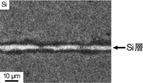
- the SEM photograph of the bonding member when all the members to be bonded is alumina and the bonding material is a simple substance of silicon and a mixture of magnesium silicate (47at% Mg) is shown.
- An EPMA photograph (silicon) of the joining member is shown when all the members to be joined are alumina and the joining material is a simple substance of silicon and a mixture of magnesium silicate (47at% Mg).
- An EPMA photograph (magnesium) of the joining member is shown when all the members to be joined are alumina and the joining material is a simple substance of silicon and a mixture of magnesium silicate (47at% Mg).
- the tensile strength of the joining member at room temperature is shown when the joining member is made of alumina and a joining material containing silicon and magnesium is used.
- the horizontal axis represents the atomic percentage (at%) of magnesium, and the vertical axis represents the tensile fracture strength (MPa).
- the three-point bending strength of the bonded member at high temperature is shown when the bonded member is made of alumina and a bonding material containing silicon and magnesium is used.
- the horizontal axis represents the atomic percentage (at%) of magnesium, and the vertical axis represents the bending fracture strength (MPa).
- An SEM photograph of the joining member is shown in the case where the joining member is silicon nitride and the joining material is a simple substance of silicon and a mixture of magnesium silicate (47at% Mg).
- An EDX photograph (silicon) of the joining member is shown when all the members to be joined are silicon nitride and the joining material is a simple substance of silicon and a mixture of magnesium silicate (47at% Mg).
- An EDX photograph (magnesium) of the joining member is shown when all the members to be joined are silicon nitride and the joining material is a simple substance of silicon and a mixture of magnesium silicate (47at% Mg).
- the tensile strength of the joining member at room temperature is shown when the joining member is silicon nitride and a joining material containing silicon and magnesium is used.
- the horizontal axis represents the atomic percentage (at%) of magnesium, and the vertical axis represents the tensile fracture strength (MPa).
- the three-point bending strength of the bonded member at high temperature is shown when the bonded member is silicon nitride and a bonding material containing silicon and magnesium is used.
- the horizontal axis represents the atomic percentage (at%) of magnesium, and the vertical axis represents the bending fracture strength (MPa).
- the tensile strength of the joining member at room temperature is shown when the joining member is made of silicon carbide and a joining material containing silicon and magnesium is used.
- the horizontal axis represents the atomic percentage (at%) of magnesium, and the vertical axis represents the tensile fracture strength (MPa).
- the present invention provides a bonding material for bonding between ceramics or between ceramics and metals, which comprises silicon and a metal having a vapor pressure of 0.1 Pa or more at 1000 ° C.
- containing silicon or metal means that each of them is contained as an element, regardless of whether it is a simple substance or a compound, or one kind of compound or a plurality of compounds. Absent. Therefore, the bonding material of the present invention may contain only one kind of siliceous metal, or silicon and the metal may be a simple substance or one or more kinds of compounds, respectively.
- ceramics means ceramics in a broad sense such as an inorganic sintered body, and not only classic ceramics made from natural raw materials, but also aluminum oxide (alumina), silicon carbide, silicon nitride, zirconia, etc. So-called fine ceramics are also included.
- the ceramics to be joined may be ceramics having the same component or ceramics having different components.
- the ceramics to be bonded may be the first member to be bonded of alumina ceramics and the second member to be bonded of alumina ceramics, or the first member to be bonded of alumina ceramics and the second member of silicon carbide ceramics. It may be a joining member.
- the shape including the joint surface of the ceramics may be any shape.
- the metal bonded member to be bonded to the ceramics bonded member may be any metal bonded member usually used by those skilled in the art in terms of composition, shape and the like.
- the material for joining means a material used for joining between two members to be joined, and does not need to have exactly the same composition after the completion of joining. That is, after applying the joining material between the two members to be joined, the composition of the material is chemically or physically changed by performing joining work such as heating to achieve joining between the two members. A joining member is obtained. Therefore, in the present invention, the joining member means a layered member that has actually achieved joining between the members to be joined, and is a joining material to be applied between the members to be joined before the joining is actually achieved. Are distinguished.
- the metal having a vapor pressure of 0.1 Pa or more at 1000 ° C. refers to ordinary vapors of groups 1 to 12 of the Periodic Table of the Elements, excluding hydrogen, such as the efusion method, the evaporation method, and the flow method.
- a simple substance of a metal is a metal element having a boiling point of 1000 ° C. or lower at 0.1 Pa or a vapor pressure of 0.1 Pa or more at 1000 ° C.
- the number of metals may be one or more, but it is preferable that the number of metals is one from the viewpoint of ease of control of reaction and necessity. Since the vapor pressure curve of a single metal is known, the metal may be selected by referring to those documents.
- the metal having a vapor pressure of 0.1 Pa or more at 1000 ° C. includes, but is not limited to, magnesium, lithium, calcium, sodium and the like.
- the metal contained in the bonding material of the present invention preferably has a vapor pressure of 1 Pa or more at 1000 ° C. so that the bonding operation can be performed under conditions of lower temperature or closer to atmospheric pressure. It is preferably 10 Pa or more, more preferably 1x10 2 Pa or more, and extremely preferably 1x10 4 Pa or more.
- the metal element may be selected in consideration of the ease of handling and availability of the metal simple substance or metal compound to be used. Considering these viewpoints comprehensively, a particularly preferable metal having a vapor pressure at 1000 ° C. of 0.1 Pa or more is magnesium, which is known to have a vapor pressure at 1000 ° C. of about 3 ⁇ 10 4 Pa. is there.
- the silicon contained in the bonding material of the present invention may contain silicon as an element and may be a simple substance of silicon, but it is also preferable that it is a silicide.
- Silicide includes, but is not limited to, for example, nickel silicate, lithium silicate, calcium silicate, sodium silicate, magnesium silicate and the like.
- a silicide of the metal that is, a silicid metal, for example, calcium silicate , Sodium silicate or magnesium silicate, etc. are understood to be sufficient.
- the bonding material of the present invention includes a simple substance of silicon, further, in addition to a metal silicide having a vapor pressure of 0.1 Pa or more at 1000 ° C. It may contain silicides, elemental metals or additional metal compounds.
- the melting point of a simple substance of silicon is 1414 ° C., but the melting point of a mixture of a simple substance of silicon and a siliceous metal is lower than that of a simple substance of silicon due to an eutectic reaction. Similar eutectic reactions can occur with mixtures of elemental silicon and / or silicide with elemental metals and / or metals silicides. In a mixture of silicon and metal in which such a eutectic reaction occurs, if the temperature is equal to or higher than the eutectic temperature, a part or all of the mixture becomes a eutectic phase even if the temperature is lower than the melting point of silicon alone.
- metal silicates are also lower than 1414 ° C, for example calcium silicate has a melting point of about 1020 ° C and magnesium silicate has a melting point of about 1100 ° C. Then, after melting the bonding material of the present invention to obtain a eutectic phase of silicon and metal, the metal is evaporated to obtain a bonding member of silicon alone.
- the metal and the components of the ceramic component to be bonded may react to form a layer of the metal compound of the ceramic component.
- the layer of the compound can be sufficiently expected to contribute to stronger bonding by modifying the bonding surface of the ceramic material to be bonded, and is rather a preferable by-product.
- alumina Al 2 O 3
- magnesium used as the metal
- the alumina reacts with magnesium and the simple substance of silicon forms a dense layer.
- MgAl 2 O 4 layer and Si layer And a joining member containing MgAl 2 O 4 layer is obtained. Since the melting point of MgAl 2 O 4 is 2130 ° C.
- the bonding member of the present invention is extremely excellent in heat resistance.
- Magnesium, lithium, calcium and sodium exemplified above as metals having a vapor pressure of 0.1 Pa or more at 1000 ° C. have good reactivity with ceramics and are strengthened by modifying the joint surface of the ceramics to be bonded member. It is a preferable metal from the viewpoint that it is easy to obtain a good bonding state.
- the metal in the metal compound layer of the ceramic component is 1000 ° C., which is a bonding member between ceramics or between ceramics and metal and includes a metal compound layer of a ceramic component and a single layer of silicon.
- a joining member characterized in that the steam pressure in the above is 0.1 Pa or more.
- the above eutectic temperature varies depending on the type of metal element to be combined with silicon, but the liquidus line (all of the mixture is liquid) with respect to the composition of the metal element (both atomic percentage and at%) in the mixture of silicon and metal.
- the relationship between the lower limit temperature that can exist in the phase state) and the solid phase line (eutectic isotherm line) (the upper limit temperature that the entire mixture can exist in the solid phase state) is shown in the phase diagram. It can be easily obtained by showing.
- the triple point where two liquid phase lines and one solid phase line intersect is the eutectic point, and the temperature and composition corresponding to that point are the eutectic temperature and the eutectic composition, respectively.
- the atomic percentage of the metal element in the mixture of silicon and metal means that 0 at% means only a simple substance of silicon, and 100 at% means that it is only a simple substance of metal. In the range of more than 0 at% and less than 100 at%, it means a state in which silicon and metal are mixed as elements, but the form may include elemental silicon, silicide, elemental metal, or metal silicate. .. Examples of such combinations may be silicate metal alone, silicon singular and silicate metal, silicon singular and metal singular, silicate and silicate metal, silicate and metal alone, and silicon.
- 66.7 at% Mg means a mixture of silicon and magnesium containing 66.7 at% of magnesium (including the case of magnesium silicate (Mg 2 Si) alone).
- 0 to 66.6 at% Mg means a simple substance of silicon or a mixture of silicon and magnesium (which may be magnesium silicate (Mg 2 Si)) containing magnesium at 66.6 at% or less.
- the eutectic points of magnesium and silicon are a eutectic composition of 47 at% Mg and a eutectic temperature of 945.6 ° C.
- the important point here is that the silicon is sufficiently liquefied under the desired bonding conditions (temperature, pressure and heating time). This is because if the liquefaction of silicon is insufficient, the powder of the material silicon may remain in the joining member and cause cracks and voids.
- the atomic percentage of the metal required to obtain such a melting point drop can be easily obtained from the phase diagram for obtaining the eutectic point, for example, 20 at% or more (1/4 of the metal as an atom with respect to silicon). Above), preferably 25 at% or more (metal is 1/3 or more as an atom with respect to silicon), and more preferably 33.3 at% or more (metal is 1/2 or more as an atom with respect to silicon).
- the solids may be dispersed in a suitable carrier when applied to a member to be joined.
- the carrier is preferably a liquid applicable to a ceramic or metal surface and easily evaporates at 1000 ° C. or lower, for example 600 ° C. or lower, which is typical. Specific examples include, but are not limited to, polyethylene glycol, water, ethanol, isopropyl alcohol and the like.
- the carrier is preferably one that easily evaporates at 1000 ° C. or lower, for example, 600 ° C.
- a foil shape for example, polyacetal. It includes, but is not limited to, resins, acrylic resins, polyethylene, paraffin and the like. Silicon dispersed in the carrier and a metal having a vapor pressure of 0.1 Pa or more at 1000 ° C. are also included in the bonding material of the present invention.
- the joining material of the present invention further improves the wettability of the joining material, adjusts the coefficient of thermal expansion, improves the adhesiveness with the member to be joined, improves the strength of the joining member, or improves the heat resistance of the joining member.
- additives commonly used in the art may be included. Examples of such additives include, but are not limited to, elemental carbon (so-called carbon powder), silicon carbide (SiC) particles, alumina (Al 2 O 3 ) particles, and the like. For example, by adding carbon powder, silicon and carbon react with each other to obtain a bonding member containing silicon carbide having high heat resistance.
- the present invention provides a method of using the bonding material of the present invention, that is, a method of joining two ceramic members or a ceramic member and a metal member.
- the present invention is a method of joining two ceramic members or a ceramic member and a metal member. 1) A step of applying the bonding material of the present invention between both members, 2) A step of heating both members to which the bonding material is applied to obtain a eutectic phase of silicon and metal, and 3) a step of further heating to evaporate the metal and obtain a single layer of silicon.
- Provide methods including.
- the joining material of the present invention used in the joining method of the present invention is as described above, and the joining material which is particularly preferable above can be used. All detailed descriptions of the preferred joining materials of the present invention and the like shall apply mutatis mutandis to the joining method of the present invention.
- the step 1) in the joining method of the present invention is a step of applying the joining material of the present invention between the joining surface of the first member to be joined and the joining surface of the second member to be joined.
- the application means that the powder may be placed on the joint surface as it is, the foil-like bonding material of the present invention may be sandwiched, or the bonding surface of the present invention may be the powder as it is.
- the powder may be dispersed in a carrier to prepare, for example, a paste-like, paste-like or liquid bonding material of the present invention and apply it.
- the applied amount of the bonding material of the present invention is an amount usually understood as an appropriate amount in the field of bonding ceramics, and is not particularly limited.
- Step 2) in the joining method of the present invention is a step of melting the joining material of the present invention by heating.
- the heating temperature varies depending on the composition of the bonding material of the present invention actually used, but can be easily determined by creating a melting point of each component and a phase diagram thereof.
- the bonding material of the present invention is a simple substance of silicon and a mixture of magnesium silicate, it is heated at least at the eutectic temperature of 945.6 ° C. or higher, for example, about 1000 ° C. to about 1100 ° C.
- the bonding material of the present invention contains a carrier, it is desirable that the carrier evaporates during this step.
- polyethylene glycol has a boiling point of about 250 ° C., so that it can be sufficiently evaporated by heating to, for example, about 400 ° C.
- heating can be performed in a commercially available electric furnace or discharge plasma sintering apparatus, but is not limited to this.
- the heating time is preferably as short as possible from the viewpoint of manufacturing cost, but the heating time can be easily determined according to the composition of the bonding material of the present invention and the heating temperature.
- the heating time is It is 30 minutes or less, preferably 20 minutes or less, and more preferably 10 minutes or less.
- the metal when the eutectic phase of silicon and metal is obtained, the metal is not oxidized by oxygen in the air in an inert atmosphere, for example, in an argon atmosphere, or in a vacuum using a vacuum pump, for example. Heating may be performed.
- Step 3) in the bonding method of the present invention is a step of further heating the eutectic phase of silicon and metal obtained in step 2) to evaporate the metal component.
- Step 2) and step 3) have different purposes, but since they are both heating steps, step 2) and step 3) may be one step without distinction, and the temperature and temperature It may be a separate step that is distinguished by conditions such as depressurization.
- the conditions under which the metal evaporates can be easily understood from the vapor pressure of the metal alone. For example, when the metal is magnesium, the vapor pressure is about 3x10 4 Pa at 1000 ° C. and about 1x10 5 Pa at 1100 ° C. Therefore, for example, heating may be performed at 1100 ° C. without depressurization, or 3x10 4 at 1100 ° C.
- Heating may be carried out by reducing the pressure to Pa or less, for example 1x10 4 Pa or less, for example 1x10 2 Pa or less, preferably 10 Pa or less, or 3x10 4 Pa or less, for example 1x10 4 Pa or less, for example 1x10 2 Pa or less at 1000 ° C. , Preferably, the pressure may be reduced to 10 Pa or less for heating. If the pressure is not sufficiently reduced, heating may be carried out in an inert atmosphere, for example, in an argon atmosphere, in order to avoid the reaction between oxygen in the air and the metal.
- the eutectic phase becomes silicon-rich and the melting point rises, and silicon solidifies by isothermal solidification. That is, as the metal evaporates, the melting point approaches 1414 ° C., which is the original melting point of silicon, and the liquid phase cannot be maintained, and silicon solidifies. Due to this property, the preferred joining member of the present invention is characterized in that it does not melt even when reheated to about the joining temperature.
- the joint member of the present invention thus obtained may be subjected to a strength test usually performed in the technical field in order to confirm whether the joint strength is sufficient.
- a strength test is not particularly limited, but for example, a tensile test in which each member to be joined of the joint is fixed and pulled to measure the breaking strength, or a tensile test in which one member of the joint is fixed and the other member is fixed.
- a shear test can be performed to measure the shear fracture stress by applying a lateral load (direction parallel to the joint surface) to the member to be joined.
- a strength test conforming to a standard such as JIS may be performed, and the test can be performed according to, for example, JIS R1624 or JIS R1606-1995.
- the joint strength is insufficient and the member to be joined of any of the ceramics is broken. May determine that the joint strength is sufficient.
- the member to be joined of the ceramic is a block of alumina, silicon nitride or silicon carbide, if there is a tensile fracture stress of, for example, about 5 MPa, preferably 10 MPa, more preferably 15 MPa, still more preferably 20 MPa at room temperature. It can be said that the joint is strong enough.
- a rectangular parallelepiped having a bottom surface (joining surface) of 4 mm x 8 mm was cut out from a plate material (purity 99.6%, plate thickness 5 mm) of an alumina (Al 2 O 3 ) sintered body.
- the joint surface was left as it was accepted (about 0.5 ⁇ mRa), and only acetone washing was performed.
- Example 5 Mixtures of magnesium silicate and silicon alone were added to 20 at% Mg (Example 1), 43 at% Mg (Example 2), 47 at% Mg (Example 3), 53 at% Mg (Example 4) and 59 at% Mg (Example 4). Prepared as Example 5).
- Example 6 only magnesium silicate (Example 6) and only silicon (Comparative Example 1) were dispersed in polyethylene glycol (PEG) to prepare each paste.
- PEG polyethylene glycol
- Each of the above butt samples was bonded by pulse energization heating using a discharge plasma sintering (SPS) apparatus. Specifically, the sample was inserted into a graphite die, sandwiched between both ends with graphite punches, and further sandwiched between the electrodes in the SPS device from above and below, and held so that a constant pressure (10 MPa) was applied to the joint surface. The vacuum was exhausted to about 10 Pa, the holding temperature was 1100 ° C., the holding time was 10 minutes, and pulse energization heating was performed. PEG was evaporated and decomposed at about 250 ° C. during temperature rise and removed in vacuum.
- SPS discharge plasma sintering
- the tensile strength of the conjugate at room temperature was tested. Specifically, each member to be joined was fixed and one member to be joined was pulled, and the fractured portion and the tensile strength at the time when the fracture occurred were measured. The relationship between the room temperature tensile strength of the bonded body and the initial Mg composition of the paste is shown in FIG. Both were broken near the joint.
- the tensile strength of 0 at% Mg (Comparative Example) was 5 MPa or less, whereas the tensile strength of 20 at% Mg (Example 1) increased to about 10 MPa, and that of 43 at% Mg (Example 2) exceeded 20 MPa. , 53 at% Mg (Example 4) markedly increased to about 30 MPa on average. Even the paste containing only magnesium silicate (Example 6) showed a high tensile strength of about 30 MPa on average.
- Examples 2, 3 and 4 a three-point bending strength test at a high temperature was also performed. Specifically, two rectangular parallelepipeds of 8 mm x 21 mm are cut out from a plate of an alumina sintered body having a thickness of 5 mm, and the 5 mm x 8 mm surfaces of each rectangular parallelepiped are used as joint surfaces, and the pastes of Examples 2, 3 and 4 are used to describe the above Examples. Bonds were prepared in the same manner as in 1 to 6. The joints were cut into 4 mm x 5 mm x 42 mm, polished, heated in the air at a heating rate of 5 ° C./min for 4 hours until reaching 1200 ° C., and then held at 1200 ° C. for another 30 minutes.
- the sintered body is silicon nitride (Si 3 N 4 ), and the mixture is 20 at% Mg (Example 7), 37 at% Mg (Example 8), 43 at% Mg (Example 9), 47 at% Mg (Example 10). ), 53 at% Mg (Example 11) and 59 at% Mg (Example 12).
- each paste was prepared by dispersing only a simple substance of silicon (Comparative Example 2) or only magnesium silicate (Example 13) in polyethylene glycol (PEG). Each paste was applied to a silicon nitride sample piece, and bonding was performed in the same manner as described above.
- Si 3 N 4 could be joined without cracking or deformation.
- the joint structure was observed and evaluated by SEM, energy dispersive X-ray analysis (EDX), and X-ray diffractometer (XRD).
- the SEM image of the joint structure with 47 at% Mg paste (Example 10) is shown in FIG. 7, and the EDX image is shown in FIGS. 8 and 9.
- EDX energy dispersive X-ray analysis
- XRD X-ray diffractometer
- Example 7 For Examples 7 to 13 and Comparative Example 1, the tensile strength of the bonded body at room temperature was tested in the same manner as described above. The results are shown in FIG. With 37 at% Mg (Example 8), the tensile strength increased to about 12 to 25 MPa, and with 43 to 59 at% Mg (Examples 9 to 12), it exceeded 25 MPa in most cases, and even exceeded 40 MPa. Even magnesium silicate alone (Example 13) showed a tensile strength of about 10 to 20 MPa.
- the sintered body is silicon carbide (SiC), and the mixtures are 37 at% Mg (Example 14), 43 at% Mg (Example 15), 47 at% Mg (Example 16), 53 at% Mg (Example 17) and 59 at. Prepared as% Mg (Example 18).
- only magnesium silicate (Example 19) was dispersed in polyethylene glycol (PEG) to prepare each paste.
- PEG polyethylene glycol
- Each paste was applied to a silicon carbide sample piece and bonded in the same manner as described above.
- the results of testing the tensile strength of the bonded body at room temperature in the same manner as above are shown in FIG.
- the tensile strength of 37 to 47 at% Mg (Examples 14 to 16) increased to about 10 MPa
- that of 53 at% Mg (Example 17) increased to about 15 MPa.
Landscapes
- Chemical & Material Sciences (AREA)
- Engineering & Computer Science (AREA)
- Ceramic Engineering (AREA)
- Materials Engineering (AREA)
- Structural Engineering (AREA)
- Organic Chemistry (AREA)
- Ceramic Products (AREA)
Priority Applications (1)
| Application Number | Priority Date | Filing Date | Title |
|---|---|---|---|
| JP2021537373A JP7684535B2 (ja) | 2019-08-07 | 2020-08-06 | セラミックス接合材 |
Applications Claiming Priority (2)
| Application Number | Priority Date | Filing Date | Title |
|---|---|---|---|
| JP2019145396 | 2019-08-07 | ||
| JP2019-145396 | 2019-08-07 |
Publications (1)
| Publication Number | Publication Date |
|---|---|
| WO2021025106A1 true WO2021025106A1 (ja) | 2021-02-11 |
Family
ID=74502735
Family Applications (1)
| Application Number | Title | Priority Date | Filing Date |
|---|---|---|---|
| PCT/JP2020/030156 Ceased WO2021025106A1 (ja) | 2019-08-07 | 2020-08-06 | セラミックス接合材 |
Country Status (2)
| Country | Link |
|---|---|
| JP (1) | JP7684535B2 (https=) |
| WO (1) | WO2021025106A1 (https=) |
Citations (3)
| Publication number | Priority date | Publication date | Assignee | Title |
|---|---|---|---|---|
| JP2000327442A (ja) * | 1999-05-14 | 2000-11-28 | Ngk Spark Plug Co Ltd | セラミックスと金属の接合体および製造方法並びに高温型二次電池 |
| JP2012116683A (ja) * | 2010-11-30 | 2012-06-21 | Showa Denko Kk | アルミニウムろう付品の製造方法 |
| JP2018032732A (ja) * | 2016-08-24 | 2018-03-01 | 三菱マテリアル株式会社 | セラミックス/Al−SiC複合材料接合体の製造方法、及びヒートシンク付パワーモジュール用基板の製造方法 |
Family Cites Families (1)
| Publication number | Priority date | Publication date | Assignee | Title |
|---|---|---|---|---|
| JPS61132569A (ja) * | 1984-11-29 | 1986-06-20 | 有限会社 宮田技研 | シリコン窒化物系セラミツク融着性合金 |
-
2020
- 2020-08-06 JP JP2021537373A patent/JP7684535B2/ja active Active
- 2020-08-06 WO PCT/JP2020/030156 patent/WO2021025106A1/ja not_active Ceased
Patent Citations (3)
| Publication number | Priority date | Publication date | Assignee | Title |
|---|---|---|---|---|
| JP2000327442A (ja) * | 1999-05-14 | 2000-11-28 | Ngk Spark Plug Co Ltd | セラミックスと金属の接合体および製造方法並びに高温型二次電池 |
| JP2012116683A (ja) * | 2010-11-30 | 2012-06-21 | Showa Denko Kk | アルミニウムろう付品の製造方法 |
| JP2018032732A (ja) * | 2016-08-24 | 2018-03-01 | 三菱マテリアル株式会社 | セラミックス/Al−SiC複合材料接合体の製造方法、及びヒートシンク付パワーモジュール用基板の製造方法 |
Non-Patent Citations (1)
| Title |
|---|
| YANG TUOYU, ZHANG DEKU, WANG KEHONG, HUANG JUN: "Aluminium-Silicon-Magnesium Filler Metal for Aluminium Vacuum Brazing Wettability and Characteristics of Brazing Microstructure", MATERIALS TRANSACTIONS, THE JAPANESE INSTITUTE OF METALS AND MATERIALS, JP, vol. 57, no. 6, 1 January 2016 (2016-01-01), JP, pages 983 - 987, XP055792135, ISSN: 1345-9678, DOI: 10.2320/matertrans.M2016004 * |
Also Published As
| Publication number | Publication date |
|---|---|
| JPWO2021025106A1 (https=) | 2021-02-11 |
| JP7684535B2 (ja) | 2025-05-28 |
Similar Documents
| Publication | Publication Date | Title |
|---|---|---|
| US5975407A (en) | Method using a thick joint for joining parts in SiC-based materials by refractory brazing and refractory thick joint thus obtained | |
| JP6026285B2 (ja) | 非反応性のろう付けによりSiC系材料製の部品を接合する方法、ろう付け組成物、ならびにこの方法により得られる接合部および組付体 | |
| JP5122049B2 (ja) | 非反応性耐火性ろう付けによりSiCベースの材料からなる部材を組立てるための方法、ろう付け用はんだ組成物ならびにこの方法により得られる耐火接合および組立て品 | |
| Zhang et al. | Microstructure and brazing mechanism of porous Si3N4/Invar joint brazed with Ag-Cu-Ti/Cu/Ag-Cu multi-layered filler | |
| JP6026287B2 (ja) | 追加の強化材を使用した非反応性のろう付けによりSiC系材料製の部品を接合する方法、ろう付け組成物、ならびにそのような方法により得られる接合部および組付体 | |
| US8763883B2 (en) | Method for assembling parts made of SiC materials by non-reactive brazing, brazing compositions, and joint and assembly obtained by said method | |
| JP4936261B2 (ja) | 炭化ホウ素含有セラミックス接合体及び該接合体の製造方法 | |
| JP6026286B2 (ja) | 非反応性のろう付けによりSiC系材料の部品を接合する方法、ろう付け組成物、ならびにこの方法により得られる接合部および組付体 | |
| JP5665295B2 (ja) | 非反応性ろう付によるSiC系材料製物品の適度に耐火性の組立プロセス、ろう付組成物、並びにこのプロセスによって得られる接合部及び組立品 | |
| CA2679846C (en) | Metal-ceramic composite air braze with ceramic particulate | |
| Chen et al. | Interfacial microstructure and strength of partial transient liquid-phase bonding of silicon nitride with Ti/Ni multi-interlayer | |
| US10093582B2 (en) | Process for the moderately refractory assembling of articles made of SiC-based materials by non-reactive brazing in an oxidizing atmosphere, brazing compositions, and joint and assembly obtained by this process | |
| Xiong et al. | V-containing-active high-temperature brazes for ceramic joining | |
| JPH0624854A (ja) | セラミックス−金属接合体 | |
| WO2021025106A1 (ja) | セラミックス接合材 | |
| Koltsov et al. | Brazing of AlN to SiC by a Pr silicide: Physicochemical aspects | |
| JP5809884B2 (ja) | 炭化ホウ素含有セラミックス接合体及び該接合体の製造方法 | |
| Xie et al. | Effects of chemical compositions of adhesive and joining processes on bond strength of Si3N4/Si3N4 joints | |
| CN120862155A (zh) | Si-Cr高温钎料及其制备方法与钎焊连接碳化硅基材料的应用 | |
| JPH05148047A (ja) | 窒化けい素セラミツクス接合体 | |
| JP2001114575A (ja) | セラミックスとセラミックスとの接合体及びその接合方法 |
Legal Events
| Date | Code | Title | Description |
|---|---|---|---|
| 121 | Ep: the epo has been informed by wipo that ep was designated in this application |
Ref document number: 20850964 Country of ref document: EP Kind code of ref document: A1 |
|
| ENP | Entry into the national phase |
Ref document number: 2021537373 Country of ref document: JP Kind code of ref document: A |
|
| NENP | Non-entry into the national phase |
Ref country code: DE |
|
| 122 | Ep: pct application non-entry in european phase |
Ref document number: 20850964 Country of ref document: EP Kind code of ref document: A1 |