WO2021024733A1 - 情報処理装置及びその制御方法 - Google Patents
情報処理装置及びその制御方法 Download PDFInfo
- Publication number
- WO2021024733A1 WO2021024733A1 PCT/JP2020/027601 JP2020027601W WO2021024733A1 WO 2021024733 A1 WO2021024733 A1 WO 2021024733A1 JP 2020027601 W JP2020027601 W JP 2020027601W WO 2021024733 A1 WO2021024733 A1 WO 2021024733A1
- Authority
- WO
- WIPO (PCT)
- Prior art keywords
- inspection
- unit
- information
- quality
- data
- Prior art date
- Legal status (The legal status is an assumption and is not a legal conclusion. Google has not performed a legal analysis and makes no representation as to the accuracy of the status listed.)
- Ceased
Links
Images


Classifications
-
- G—PHYSICS
- G06—COMPUTING OR CALCULATING; COUNTING
- G06F—ELECTRIC DIGITAL DATA PROCESSING
- G06F3/00—Input arrangements for transferring data to be processed into a form capable of being handled by the computer; Output arrangements for transferring data from processing unit to output unit, e.g. interface arrangements
- G06F3/12—Digital output to print unit, e.g. line printer, chain printer
- G06F3/1201—Dedicated interfaces to print systems
- G06F3/1202—Dedicated interfaces to print systems specifically adapted to achieve a particular effect
- G06F3/1203—Improving or facilitating administration, e.g. print management
- G06F3/1207—Improving or facilitating administration, e.g. print management resulting in the user being informed about print result after a job submission
-
- B—PERFORMING OPERATIONS; TRANSPORTING
- B41—PRINTING; LINING MACHINES; TYPEWRITERS; STAMPS
- B41J—TYPEWRITERS; SELECTIVE PRINTING MECHANISMS, i.e. MECHANISMS PRINTING OTHERWISE THAN FROM A FORME; CORRECTION OF TYPOGRAPHICAL ERRORS
- B41J29/00—Details of, or accessories for, typewriters or selective printing mechanisms not otherwise provided for
- B41J29/38—Drives, motors, controls or automatic cut-off devices for the entire printing mechanism
- B41J29/393—Devices for controlling or analysing the entire machine ; Controlling or analysing mechanical parameters involving printing of test patterns
-
- B—PERFORMING OPERATIONS; TRANSPORTING
- B41—PRINTING; LINING MACHINES; TYPEWRITERS; STAMPS
- B41J—TYPEWRITERS; SELECTIVE PRINTING MECHANISMS, i.e. MECHANISMS PRINTING OTHERWISE THAN FROM A FORME; CORRECTION OF TYPOGRAPHICAL ERRORS
- B41J29/00—Details of, or accessories for, typewriters or selective printing mechanisms not otherwise provided for
- B41J29/42—Scales and indicators, e.g. for determining side margins
-
- G—PHYSICS
- G06—COMPUTING OR CALCULATING; COUNTING
- G06F—ELECTRIC DIGITAL DATA PROCESSING
- G06F3/00—Input arrangements for transferring data to be processed into a form capable of being handled by the computer; Output arrangements for transferring data from processing unit to output unit, e.g. interface arrangements
- G06F3/12—Digital output to print unit, e.g. line printer, chain printer
- G06F3/1201—Dedicated interfaces to print systems
- G06F3/1202—Dedicated interfaces to print systems specifically adapted to achieve a particular effect
- G06F3/1203—Improving or facilitating administration, e.g. print management
- G06F3/1208—Improving or facilitating administration, e.g. print management resulting in improved quality of the output result, e.g. print layout, colours, workflows, print preview
-
- G—PHYSICS
- G06—COMPUTING OR CALCULATING; COUNTING
- G06F—ELECTRIC DIGITAL DATA PROCESSING
- G06F3/00—Input arrangements for transferring data to be processed into a form capable of being handled by the computer; Output arrangements for transferring data from processing unit to output unit, e.g. interface arrangements
- G06F3/12—Digital output to print unit, e.g. line printer, chain printer
- G06F3/1201—Dedicated interfaces to print systems
- G06F3/1223—Dedicated interfaces to print systems specifically adapted to use a particular technique
- G06F3/1237—Print job management
- G06F3/1253—Configuration of print job parameters, e.g. using UI at the client
- G06F3/1256—User feedback, e.g. print preview, test print, proofing, pre-flight checks
-
- G—PHYSICS
- G06—COMPUTING OR CALCULATING; COUNTING
- G06F—ELECTRIC DIGITAL DATA PROCESSING
- G06F3/00—Input arrangements for transferring data to be processed into a form capable of being handled by the computer; Output arrangements for transferring data from processing unit to output unit, e.g. interface arrangements
- G06F3/12—Digital output to print unit, e.g. line printer, chain printer
- G06F3/1201—Dedicated interfaces to print systems
- G06F3/1223—Dedicated interfaces to print systems specifically adapted to use a particular technique
- G06F3/1237—Print job management
- G06F3/1268—Job submission, e.g. submitting print job order or request not the print data itself
- G06F3/1272—Digital storefront, e.g. e-ordering, web2print, submitting a job from a remote submission screen
-
- G—PHYSICS
- G06—COMPUTING OR CALCULATING; COUNTING
- G06F—ELECTRIC DIGITAL DATA PROCESSING
- G06F3/00—Input arrangements for transferring data to be processed into a form capable of being handled by the computer; Output arrangements for transferring data from processing unit to output unit, e.g. interface arrangements
- G06F3/12—Digital output to print unit, e.g. line printer, chain printer
- G06F3/1201—Dedicated interfaces to print systems
- G06F3/1278—Dedicated interfaces to print systems specifically adapted to adopt a particular infrastructure
- G06F3/1282—High volume printer device
-
- G—PHYSICS
- G06—COMPUTING OR CALCULATING; COUNTING
- G06F—ELECTRIC DIGITAL DATA PROCESSING
- G06F3/00—Input arrangements for transferring data to be processed into a form capable of being handled by the computer; Output arrangements for transferring data from processing unit to output unit, e.g. interface arrangements
- G06F3/12—Digital output to print unit, e.g. line printer, chain printer
- G06F3/1201—Dedicated interfaces to print systems
- G06F3/1278—Dedicated interfaces to print systems specifically adapted to adopt a particular infrastructure
- G06F3/1285—Remote printer device, e.g. being remote from client or server
- G06F3/1287—Remote printer device, e.g. being remote from client or server via internet
-
- G—PHYSICS
- G06—COMPUTING OR CALCULATING; COUNTING
- G06F—ELECTRIC DIGITAL DATA PROCESSING
- G06F3/00—Input arrangements for transferring data to be processed into a form capable of being handled by the computer; Output arrangements for transferring data from processing unit to output unit, e.g. interface arrangements
- G06F3/12—Digital output to print unit, e.g. line printer, chain printer
- G06F3/1201—Dedicated interfaces to print systems
- G06F3/1202—Dedicated interfaces to print systems specifically adapted to achieve a particular effect
- G06F3/1203—Improving or facilitating administration, e.g. print management
- G06F3/1204—Improving or facilitating administration, e.g. print management resulting in reduced user or operator actions, e.g. presetting, automatic actions, using hardware token storing data
Definitions
- the present invention relates to quality requirements for printed products.
- Patent Document 1 discloses a method of setting points (representative points) on an image for comparing image data.
- the ordering party When making a quality request, the ordering party must specify where to perform the quality inspection on the deliverable.
- PRX which is an example of quality requirement data
- PRX is a specification in which the inspection position is specified by coordinates. That is, when the arrangement of the image of the print data is changed, the image is not changed, and even if the arrangement of the image is only changed, there is a problem that the inspection position must be redesignated each time.
- the ordering party could not flexibly specify the inspection target of the deliverable.
- the information processing apparatus of the present invention has an acquisition means for acquiring instruction information for quality inspection of printed matter, and whether the inspection target is specified by object identification information in the instruction information or coordinate information. It is characterized by having a determination means for determining whether or not it is specified in, and an inspection means for identifying an inspection position based on the determination result and performing a quality inspection of printed matter using the identified inspection position.
- the ordering party can flexibly specify the inspection target of the deliverable.
- the first figure for demonstrating the operation part of the application system in 1st Embodiment The first figure for demonstrating the operation part of the application system in 1st Embodiment
- the second figure for demonstrating the operation part of the application system in 1st Embodiment The second figure for demonstrating the operation part of the application system in 1st Embodiment
- An example of print settings An example of quality requirements An example of test results An example of quality report data
- Example of inspection result in the second embodiment Schematic diagram of a data table that stores the objects to be inspected and the specifications related to the inspection.
- Soft configuration diagram of the image forming apparatus according to the third embodiment Software configuration diagram of the information processing device of the printing company system in the third embodiment The flow diagram explaining the process flow of the controller part 205 of the information processing apparatus 102 after receiving an order in 3rd Embodiment.
- Schematic diagram of a data table that stores object identifiers and inspection positions The figure explaining the example of calculating the coordinate of the inspection position from the PDF coordinate and the imposition information.
- An example of RRX (quality requirement data) An example of RRX (quality requirement data)
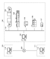
- FIG. 1 is a block diagram showing a system according to the present embodiment.
- the system is roughly divided into an orderer system 109, a printing company system 100, and a printing company's parent company system 111, which are interconnected by the Internet 108.
- the ordering party system 109 includes at least one or more information processing devices 110.
- the parent company system 111 also includes at least one or more information processing devices 112.
- a plurality of devices are connected to each other by a network 101.
- an information processing device 102 an image forming device 103, an image forming device 104, a laminator 105, a perfect binding machine 106, and a colorimeter 107 are connected.
- the image forming apparatus 103 is an image forming apparatus for a continuous book sheet
- the image forming apparatus 104 is an image forming apparatus for a cut sheet.
- Each device is controlled under the control of workflow software that operates on the information processing device 102, processes job data submitted by the ordering system 109, and produces deliverables.
- the job data submitted from the ordering party system 109 is image data, job tickets, and quality requirement data.
- the job ticket is in the JDF format, for example, and the quality requirement data is in the PRX format, for example.
- the information processing device 102 in the printing company system 100 also has a function of receiving the notification of the processing result of each device described above, converting it into quality report data, and transmitting it to the ordering party system 109.
- the format of the quality report data is, for example, the PQX format.
- the orderer can immediately grasp the quality of the product requested to be produced.
- the ordering party carries out activities to equalize quality even in the production of long-term deliverables, even if there may be time-series quality fluctuations. In addition, it can be facilitated by the printing company.
- the ordering party and the printing company carry out activities to visualize the quality variation among the plurality of printing companies and at the same time to make the quality uniform. Can be facilitated.
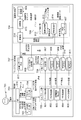
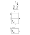
- FIG. 2 is a diagram illustrating a hardware configuration of the image forming apparatus 104.
- the image forming apparatus 104 has a reading function for reading an image on a sheet and a printing function for printing an image on the sheet.
- the image forming apparatus 104 has a post-processing function of binding a plurality of sheets on which an image is printed, aligning the plurality of sheets, and dividing the ejection destinations of the plurality of sheets into a plurality of trays.
- the sheet includes paper such as plain paper and thick paper, a film sheet, and the like.
- the image forming apparatus 104 shown in the figure is configured so that a plurality of devices having different roles are connected to each other to enable complicated sheet processing.
- the image forming apparatus 104 is an apparatus for conveying the developed image image data to a medium stored in the paper feeding unit 212 and forming an image on the medium by using toner.
- the image forming apparatus 104 is provided with a scanner unit 201 and an operation unit 204.
- the operation unit 204 provides various interfaces when the operator performs various settings and operations of the image forming apparatus 104.
- the image forming apparatus 104 in the present embodiment is configured so that various accompanying devices can be attached.
- the sheet processing device 210 is shown as an example of the accompanying device.
- the sheet processing device 210 is a device for obtaining a product product obtained by performing various processing on the media after the image is formed by the printer unit 203.
- the output tray 213 forms a tray portion for discharging and loading the output material processed by the sheet processing device 210.
- the inspection unit 214 is a module provided for inspecting the image information formed on the sheet by the printer unit 203.
- the objects to be inspected include the amount of print position deviation (registration deviation amount) of each CMYK plate, and the difference (color difference) between the color formed by synthesizing the CMYK plates and the color defined by the print data. Others are image defects such as reading accuracy of the barcode portion included in the formed image, rubbing and scratches on the image, and the like.
- the module has a function of optically reading the image of the sheet after image formation and converting these image defects into inspection result data.
- the hard disk 209 (hereinafter, also referred to as HDD) is a non-volatile memory, and stores data of a plurality of jobs to be processed, various management information, and the like.
- the job data received from the scanner unit 201 is printed by the printer unit 203 via the HDD 209.
- the job data received from the external device via the external I / F unit 202 unit corresponding to an example of the communication unit is printed by the printer unit 203 via the HDD 209.
- the external I / F unit 202 transmits and receives image data and the like to and from a facsimile, a network connection device, and an external dedicated device.
- the operation unit 204 corresponds to a user interface unit, and here, has a display unit.
- the controller unit 205 (also referred to as a control unit or a CPU) comprehensively controls the processing and operation of various units included in the image forming apparatus 104.
- the ROM 207 stores various control programs required in this embodiment, including a program for executing various processes of the flowchart described later. Further, the ROM 207 also stores a display control program for displaying various UI screens on the display unit of the operation unit 204, including the user interface screen (hereinafter referred to as a UI screen). By reading and executing the program of ROM 207, the controller unit 205 causes the image forming apparatus 104 to execute various operations described in the present embodiment.
- a program for interpreting code data forming print data such as PDF received from an external device via an external I / F 202 and executing an operation of expanding it into raster image data (bitmap image data) is also stored in ROM 207.
- a program for interpreting and processing a print job received from an external device via the external I / F 202 is also stored in the ROM 207. These are mainly processed by software. Details of various programs stored in the ROM 207 will be described later.
- the HDD 209 (hard disk) is a large-capacity storage device that stores image data compressed by the compression / decompression unit 206.
- the HDD 209 is configured to be able to hold a plurality of data such as print data of a job to be processed.
- the controller unit 205 controls the data of the job to be processed input via various input units such as the scanner unit 201 and the external I / F unit 202 so that the printer unit 203 can print the data of the job to be processed via the HDD 209. .. It also controls so that it can be transmitted to an external device via the external I / F 202. In this way, the controller unit 205 controls various output processes of the data of the job to be processed stored in the HDD 209 so that it can be executed. Further, the file system built in the HDD 209 is configured so that functions such as file sharing and transmission / reception to an external device can be realized by the controller unit 205 reading and executing the program of the ROM 207.
- the compression / decompression unit 206 performs a compression / decompression operation of image data and the like stored in the RAM 208 and the HDD 209 by various compression methods such as JBIG and JPEG.
- the controller unit 205 as an example of the control unit included in the printing system also controls the operation of each sheet processing device 210.
- the media management unit 211 is a module for managing information regarding media types.
- the inspection unit 214 is a module provided for inspecting image information formed in a sheet shape under the control of the controller unit 205 for each module constituting the image forming apparatus 104 shown in the figure. The inspection result information converted into the inspection result data by the module is transmitted to the information processing apparatus 102 via the external I / F 202.
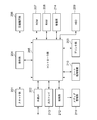
- FIG. 3 is a block diagram showing the configurations of the information processing devices 102, 110, 112.
- the CPU 301 executes a program of an OS or a general application stored in the program ROM of the ROM 303 or loaded from the HDD 311 into the RAM 302.
- the ROM 303 also has a font ROM and a data ROM.
- the RAM 302 functions as a main memory, a work area, and the like of the CPU 301.
- the keyboard controller (KBC) 305 controls input from a keyboard or a pointing device (not shown).
- the display controller CRTC306 controls the display on the display unit CRT310.
- the disk controller (DKC) 307 controls access to the boot program, various applications, the HDD 311 that stores font data, and the like.
- the network controller (NIC) 312 is connected to a network and executes communication control processing with other devices connected to the network.
- the bus 304 connects the CPU 301 to the RAM 302, the ROM 303, various controllers, and the like, and conveys data signals and control signals.
- a touch panel controller or the like may be included in the configuration instead of the keyboard controller (KBC) 305.
- KBC keyboard controller
- a large-capacity storage device that replaces the HDD 311 may be provided.
- the network controller (NIC) 312 has a different internal configuration depending on whether the device provided is a wired LAN, a wireless LAN, or both. However, the difference due to these internal configurations is concealed inside the network controller (NIC) 312, and is configured so that the system can be controlled as equivalent to the other modules shown in the figure.
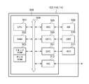
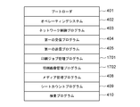
- FIG. 4 is a diagram illustrating a program of the image forming apparatus 104. These programs are stored in the ROM 207, read by the controller unit 205 of the image forming apparatus 104, and executed.
- the boot loader 401 is a program executed immediately after the power of the image forming apparatus 104 is turned on. This program contains a program for executing various boot sequences required to boot the system.
- the operating system 402 is a program for the purpose of providing an execution environment for various programs that realize the functions of the image forming apparatus 104. This mainly provides functions such as resource management of the memory of the image forming apparatus 104, that is, ROM 207, RAM 208, HDD 209, and basic input / output control of other parts shown in FIG.
- the network control program 403 is a program executed when data is transmitted / received to a device connected via a network. This program is used when executing various processes such as reception processing of a file to be printed, data transmission from an external device, command transmission / reception, and transmission of digital data generated as a result of inspection by the inspection unit 214.
- the network control program also includes a driver program for controlling the external I / F 202.
- the first receiving program 404 is a program for receiving various instructions and information from the information processing apparatus 102. The information and instructions to be received by the program include the designation of image information to be inspected by the inspection unit 214.
- the first transmission program 405 is a program for transmitting information to the information processing apparatus 102.
- the information to be transmitted by the program includes inspection result data generated as a result of inspection by the inspection unit 214.
- the JDF function program 406 is a program that executes the JDF print function executed by the controller unit 205 according to the instruction of the external I / F 202 when the JDF job data is received by the image forming apparatus 104 via the external I / F 202. ..
- the controller unit 205 sequentially instructs the operation of each device shown in FIG. 2 in an appropriate order based on the processing order and processing conditions described in this program. As a result, the JDF print process is finally controlled to be executed.
- Each device includes a sheet processing device 210, a printer unit 203, an HDD 209, a compression / decompression unit 206, a RAM 208, and the like.
- the analysis process of the JDF job data received via the external I / F202 the process of determining whether or not the JDF contains incorrect settings as a result of the analysis process, and the setting change to eliminate the incorrect settings. It also includes program processing to perform such as.
- the PDF function program 407 executes the PDF data expansion process executed by the controller unit 205 and the print function when the PDF data (print target image data) is received by the image forming apparatus 104 via the external I / F 202. To do.
- the controller unit 205 sequentially instructs the operation of each device shown in FIG. 2 in an appropriate order based on the processing order and processing conditions described in this program. As a result, the PDL print process is finally controlled to be executed.
- Each of these devices includes a sheet processing device 210, a printer unit 203, an HDD 209, a compression / decompression unit 206, a RAM 208, and the like.
- the PDF function program in the present embodiment is configured to operate together with the JDF function program 406 as various specifications when executing the print process.
- the media management program 408 is a program for executing management functions related to the sheets available to the image forming apparatus 104.
- the sheet-related information managed by this program is stored in the HDD 209.
- the sheet count program 409 manages and stores the number of sheets used for printing when the sheet stored in the paper feed unit 212 included in the image forming apparatus 104 is formed by the printer unit 203 in association with the sheet size information. It is a program to do.
- the inspection program 410 is a program for controlling the inspection unit 214, inspecting the image of the output result, and generating the inspection result data.
- the inspection result data generated by the program is transmitted to the information processing apparatus 102 by the first transmission program 405.
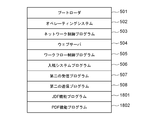
- FIG. 5 is a diagram illustrating the configuration of a program included in the information processing apparatus 102 in the printing company system 100.
- the boot loader 501 is a program executed immediately after the power of the information processing device 102 is turned on. These programs include programs for executing various boot sequences required to boot the system.
- the operating system 502 is a program for the purpose of providing an execution environment for various programs that realize the functions of the information processing apparatus 102. This provides functions such as resource management of the memory of the information processing apparatus, that is, ROM 303, RAM 302, HDD 311 and the like.
- the network control program 503 is a program executed when transmitting / receiving data to / from a device connected via a network. That is, it is used when the print job data is transmitted to the image forming apparatus (103, 104) and the print process is instructed. It is also used when instructing the laminator 105 to decorate the printed product.
- the web server 504 is a server program for allowing an external device connected via a network to use a web service. Various services provided by the web server 504 can be considered. However, in the present embodiment, an example is shown in which the ordering party system 109 provides the printing company system 100 as a means for submitting the data to be ordered. In addition, an example is shown in which the orderer also uses the PQX information, which is a quality report for confirming whether or not the quality requirement set for the printing company is achieved at the time of submission, as a means for acquiring the PQX information.
- the workflow control program 505 is a program for centrally managing processing, control, job execution, etc. between devices connected via the network 101 inside the printing company system 100, and is the core of the printing company system 100. Is. When a product is manufactured using a plurality of processes, that is, a plurality of devices, the execution order and job execution control are performed. In addition, the workflow control program 505 also executes control such as selection, switching, and recovery production of the device to be used. In addition, the workflow control program 505 also executes a process of issuing various instructions to an operator working inside the printer system 100.
- the workflow control program 505 of the present embodiment also shows an example of a mode in which the workflow control program 505 of the present embodiment also receives measurement data related to the quality of the printed image from the inspection unit 214 of the image forming apparatus 104 and converts it into a PQX format.
- the submission system program 506 is software that mainly plays a role of holding and managing the data requested for production from the orderer system 109 in the printer system 100. Further, in cooperation with the web server 504, in order to electronically execute various functions necessary for ordering / ordering-related work, for example, a series of processes such as data transmission and invoice issuance between the orderer system 109 and the printing company system 100. The system used.
- the communication specifications between the ordering party system 109 and the printing company system 100 are arbitrary, but a system that supports PrintTalk as a standard specification is widely known.
- the quality requirement receiving program 507 is a program provided for the purpose of receiving PRX, which is quality requirement data, among the data submitted from the ordering party system 109. When the program receives the PRX, it analyzes the contents and appropriately sets the instructions and conditions for creating the quality product requested by the ordering party for the device in the printing company system 100. Alternatively, the necessary information is presented to the operator.
- the printing company system 100 when the printing company system 100 receives the quality request data from the ordering party system 109, it is received via the web server 504, and the received data is received by the quality request receiving program. ..
- the quality requirement receiving program itself may receive the quality requirement data directly from the ordering party system 109.
- the quality requirement receiving program 507 may operate as web content on the web server 504.
- the quality report creation program 508 is a program for transmitting or acquiring PQX, which is quality report data. From the quality report data, it is possible to determine whether or not the printing company implements the quality conditions specified by PRX, which is the quality requirement data, at the time of production.
- Inspection result data can be received and accumulated from the image forming apparatus 103, 104 or other equipment in the printing company, converted into PQX format data at an appropriate timing, and the ordering party system 109 can receive PQX via a communication means. Is configured.
- the ordering party system 109 receives the quality report data from the printing company system 100
- the ordering party system 109 receives the request via the web server 504.
- the quality report data is transmitted as a response to the received request via the quality report creation program 507.
- the quality report creation program 507 itself may directly transmit the quality report data to the orderer system 109.
- the quality report creation program 507 may operate as web content on the web server 504.
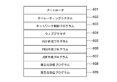
- FIG. 6 is a diagram illustrating the configuration of the program included in the information processing device 110 in the ordering party system 109.
- the boot loader 601 is a program executed immediately after the power of the information processing device 110 is turned on. These programs include programs for executing various boot sequences required to boot the system.
- the operating system 602 is a program for the purpose of providing an execution environment for various programs that realize the functions of the information processing apparatus 110. This provides functions such as resource management of the memory of the information processing apparatus, that is, ROM 303, RAM 302, HDD 311 and the like.
- the network control program 603 is a program executed when data is transmitted / received to a device connected via a network. That is, it is used when executing transmission / reception of data to / from the printing company system 100 via the Internet 108. It is also used during drawing display processing and data transmission / reception processing using a web browser, which will be described later.
- the web browser 604 is a client program program for using a web service provided by an external system connected via a network. Various services can be considered as used by the web browser 604. In the present embodiment, it is used as a means for requesting the printing company system 100 to submit data to be ordered. It is also used as a means for acquiring PQX information, which is a quality report for confirming whether or not the orderer has achieved the quality requirements set for the printing company at the time of submission.
- the PDF creation program 605 is a program for creating image data in PDF format, which is a target for which the orderer system 109 requests the printing company system 100 for production. In this embodiment, an example in which the PDF format is used as the image data format is shown, but other formats may be used.
- the creation of PDF data also includes processing such as adding an image to the existing PDF format image data.
- the PRX creation program 606 is a program for creating information for transmitting the quality requirements of the generated product in the PRX format when the orderer system 109 requests the printing company system 100 for production. is there. The specific contents of the quality requirements specified by the program, the setting method, and the created data format will be described later.
- the JDF creation program 607 is information for transmitting the form of the product to be produced, the job execution conditions at the time of production, the job setting, etc. in the JDF format when the orderer system 109 requests the printing company system 100 for production. It is a program for creating. The specific contents such as the setting information specified by the program, the setting method, and the created data format will be described later.
- the third transmission program 608 is a program used to transmit quality request data in the PRX format created by the PRX creation program 606 from the orderer system 109 to the printer system 100.
- the third reception program 609 is a program used by the ordering party system 109 to receive the quality report data created by the quality report creation program 508 in the printer system 100 from the printer system 100.
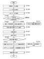
- FIG. 7 is a system flow diagram when the orderer system 109, the printer system 100, and the orderer, that is, the user who is the operator of the orderer system 109, use the functions provided by the system.
- the user 701 indicates a user of the information processing apparatus 110 in the ordering party system 109.
- the subsystem of user 701 is user operation 702. This is a column showing the contents of the operation instructed to the screen in order to realize the series of flows shown in the figure by the user and the relationship between the flows generated as a result of the operation.
- the information processing device 110 of the ordering party system 109 is disassembled into two subsystems. That is, there are two subsystems shown in the data creation application unit 703 and the browser application unit 704.
- the data creation application unit 703 is realized by the CPU 301 executing the PDF creation program 605, the PRX creation program 606, and the JDF creation program 607.
- the browser application unit 704 is realized by the CPU 301 executing the web browser 604.
- the information processing apparatus 102 of the printer system 100 is decomposed into three subsystems. That is, there are three subsystems shown in the web server unit 705, the submission system unit 706, and the workflow control unit 707.
- the web server unit 705 is realized by the CPU 301 executing the web server 504.
- the submission system unit 706 is realized by the CPU 301 executing the submission system program 506.
- the workflow control unit 707 is realized by the CPU 301 executing the workflow control program 505.
- the user 701 instructs the printing company system 100 to create the data to be ordered.
- the PDF creation program 605 receives an operation according to the instruction of the same step, and various processes for creating desired PDF image data are executed.
- the user 701 further instructs the printer system 100 to create the quality requirement data for the deliverable ordered by S711.
- the PRX creation program 606 receives an operation according to the instruction of the same step, and various processes for creating desired PRX data are executed.
- the user 701 further instructs the printer system 100 to create a job ticket for the deliverable ordered by S713.
- the JDF creation program 607 receives an operation according to the instruction of the same step, and various processes for creating desired JDF data are executed.
- the creation of the desired JDF data is completed in S714, the creation of all the data to be submitted to the printing company is completed. Therefore, from the next step onward, the data submission process to the printing company is started.
- the user operates the browser application unit 704 to perform operations necessary for displaying the operation screen for uploading data to the printing company. That is, the browser application unit 704 outputs the http request required for the drawing process to the web server unit 705 operating in the information processing device 102 on the printer side based on the URL information input in S715 in S716.
- the web server unit 705 receives the request and returns the page information as a response in S717.
- the user 701 operates the submission screen displayed in S718 and instructs the execution of the order processing on the browser application unit 704.
- the browser application unit 704 transmits each data of PDF, PRX, and JDF, that is, the submitted data, to the web server unit 705 in S719.
- the submission system unit 706 executes a process of storing each of the submitted data in S720.
- the submitted data is a step of production processing executed in the printing company system 100. That is, job data is registered in the workflow control unit 707 based on the submitted data, and a print job is generated by the printing company system 100. Further, in the system of the present embodiment, it is necessary to create and transmit PQX which is a quality report corresponding to the designated PRX. Therefore, after the job registration process is completed in S722, the submission system unit 706 instructs the workflow control unit 707 to instruct the PQX creation.
- the submission system 706 instructs the workflow control unit 707 to start production, that is, to execute the job by S725.
- the workflow control unit 707 generates a print job for the print control unit 708 that forms a component of the image forming apparatus 104 (S726).
- the print job includes information on print data, parameters used by the print control unit 708 during printing, and parameters used for quality measurement such as color measurement position.
- the print control unit 708 analyzes the PDF, the print data passed to the print control unit 708 in S726 remains in the PDF format, and the parameter indicating the color measurement position is the value of the Id of the object of the PDF. is there.
- the print control unit 708 Upon receiving the instruction of S726, the print control unit 708 starts the printing process. Then, the produced product is inspected in S727 by the inspection unit 214 included in the image forming apparatus 104. The inspection result is returned to the workflow control unit 707 in S728, and the workflow control unit 707 converts the returned inspection result into a PQX format and stores it in the web server unit 705.
- the above is a series of operation flows related to the production of data submitted from the ordering party system 109 by the printing company system 100 and the creation process of PQX which is the requested quality report information.
- the user 701 executes the PQX data acquisition process in order to confirm the quality status at the time of production of the submitted data. That is, the browser application unit 704 is accessed, and information such as a URL necessary for acquiring PQX information is input.
- the http request is transmitted from the browser application unit 704 to the web server unit 705, and the corresponding response information is returned in S732.
- the user operates the web screen returned in S732 in S733, and instructs the browser application unit 704 to acquire the quality report information, that is, PQX.
- the http request is transmitted to the web server unit 705 (S734), and the PQX information is transmitted to the user as the response.
- FIG. 8 is a system configuration diagram illustrating the processing in charge of the functional module composed of the orderer system 109 and the printer system 100 constituting the system, and the user 701 who is the operator thereof, and the relationship between the functions. The details of each part will be described below.
- the UI unit 816 is a functional unit provided to provide means for displaying image information, input / output instructions for data, and receiving operation instructions.
- the UI unit 816 gives instructions to the data creation application unit 703 and the browser application unit 704.
- the data creation application unit 703 is for providing the user with a function of creating each data of JDF, PDF, and PRX.
- the browser application unit 704 is a functional unit that is displayed on the UI unit 816 and controls the process of presenting screen information by displaying the web content on the window screen.
- the browser application unit 704 performs information transmission / reception processing with the web server unit 705, which will be described later.
- various data processes including presentation of various screen information and transfer of data to be printed, a series of functions of submission and quality request / report between the orderer system 109 and the printer system 100 are provided to the user. ..
- the web server unit 705 is a functional unit that provides the web service provided by the information processing device 102 in the printing company system 100 to the external device.
- the web server unit 705 executes a series of processes of receiving various requests from the external device, that is, returning the results of receiving the requests and executing the processes according to the contents to the outside in the form of page information.
- the page generation unit 801 is responsible for generating page information according to the content of the request. It is also possible to issue an execution instruction for the submission process to the control unit 807 of the submission system unit 706.
- the PDF transfer unit 802, the print setting transfer unit 803, and the PRX transfer unit 804 store the PDF, JDF, and PRX, which are the submission data transmitted from the browser application unit, in the submission system unit 706, respectively (808, 809, The process of transferring to 810) is executed. Further, the PRX receiving unit 805 executes a process of receiving the PRX data (811) created by the quality report creating unit 817 described later.
- the submission system unit 706 is a functional unit that provides the service related to the submission process to the external device, which is possessed by the information processing device 102 in the printing company system 100.
- the control unit 807 requests each submitted data to the job registration request unit 806 of the workflow control unit 707, and instructs the image forming apparatus 104 to execute the print job.
- the workflow control unit 707 is a functional unit for providing a workflow function possessed by the information processing apparatus 102 in the printer system 100.
- Various devices shown in FIG. 1 are connected to the workflow control unit 707 via the network 101, and under the control of the workflow control unit 707, the operation of each device and the job execution instruction are given, and the printing company The system 100 operates as a whole.
- the image forming apparatus 104 is roughly classified into a print control unit 708, a sheet management unit 409, a printing unit 815, and an inspection unit 214.
- the print control unit further includes a job execution unit 812 and a PDF interprinter unit 407.
- the job execution unit includes an image generation unit 813 and a print setting unit 814.
- the print setting unit receives the job data transmitted from the job registration request unit 806, that is, JDF809, PDF808, and PRX, and instructs the image generation unit 813 to perform the image generation process.
- the PDF interpreter 407 is instructed to analyze the received PDF808.
- the print setting unit 814 instructs the inspection unit 214 to inspect the produced deliverables for the required quality requirements of the PRX810.
- the PDF interpreter 407 transmits intermediate data (not shown) generated after analysis to the image generation unit 813, and executes subsequent image formation processing.
- the sheet management unit 409 instructs the printing unit 815 to count the size and type of the sheet used for the printing process, and forms an image of intermediate data (not shown) generated after analysis on the sheet to the printing unit 815. carry out. Further, the inspection unit 214 inspects the sheet-shaped image generated by the printing unit 815, and registers the result in the quality report creation unit 817.
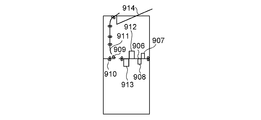
- 9A to 9C are diagrams for explaining the configuration of the inspection device, the inspection method and the mechanism performed by the inspection device, among the configurations of the image forming apparatus 104.
- FIG. 9A is a configuration diagram for explaining the arrangement of each module forming the image forming apparatus 104, the connection state thereof, and the order relationship of the sheet transport path.
- the paper feeding unit 901 is mounted in a form adjacent to the image forming unit 902. Further, the intermediate processing unit 903 is connected so as to be adjacent to the side opposite to the paper feeding unit 901.
- the intermediate processing unit 903 cools, for example, an inserter used to insert the insert paper into a specific location of the product being produced, and the heat generated on the sheet when the fixing process is performed by the image forming unit 902. A cooling device for this purpose is equivalent.
- the inspection unit 904 is mounted after the intermediate processing unit 903. Details of the configuration of the inspection unit 904 will be described later.
- a post-processing section 905 is further attached to the rear end of the inspection section 904.
- processing processing on the printed sheet is performed, such as binding processing such as staples and perforation processing such as punching.
- binding processing such as staples
- perforation processing such as punching.
- FIG. 9B is a configuration diagram for showing the internal configuration of the inspection unit 904.
- the printed sheet is transported to the transport path 906 from the device corresponding to the front stage of the inspection unit 904.
- a first inspection unit 907 and a second inspection unit 908 for inspecting the image information formed on the conveyed sheet are arranged above and below the sheet, respectively.
- This is a configuration for simultaneously inspecting the formed images of the front surface and the back surface of the sheet.
- the first inspection unit 907 and the second inspection unit 908 in the present embodiment are configured by a contact image sensor arranged in parallel with respect to the main scanning direction with respect to the sheet transported to the transport path 906.
- the first inspection unit 907 and the second inspection unit 908 by the contact image sensor read the image on the sheet conveyed to the transfer path 906 continuously in the main scanning direction according to the transfer speed of the sheet and are formed into a sheet shape. Acquires the image information of the plane with high accuracy. That is, the first inspection unit 907 and the second inspection unit 908 perform image inspections such as detection of image defects such as image misalignment and stains on the image information formed on the sheet and a barcode reading system. Is possible.
- a third inspection unit 912 and a fourth inspection unit 913 are further arranged after the first inspection unit 907 and the second inspection unit 908.
- the third inspection unit 912 and the fourth inspection unit 913 are spectrophotometric devices.
- the front and back surfaces of the sheet are arranged above and below the transport path 906 so that they can be inspected at the same time.
- the purpose of the third inspection unit 912 and the fourth inspection unit 913 is to accurately inspect the color information of the image of the sheet-shaped specific portion conveyed to the transfer path 906.
- the sheets that have passed through the first to fourth inspection units (907, 908, 912, 913) are further conveyed in the following two directions depending on the arrangement state of the flapper 909. That is, the sheet is transported to the post-processing section 905 corresponding to the rear end of the inspection section 904 via the transport path 910. Alternatively, if the transported sheet is not a part of the deliverable and is an incidental test print sheet for the purpose of checking the color and image condition, it is not a good idea to mix it with the deliverable. .. Therefore, the inspection unit 904 can also control the arrangement state of the flapper 909 so that the sheet conveys the flapper 909 to the transport path 911 and guides it to the discharge tray 914.
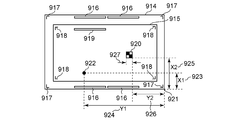
- FIG. 9C may be for explaining an example of the image information on the sheet used for the inspection performed by the first to fourth inspections (907, 908, 912, 913) included in the inspection unit 904.
- the uses and purposes of each image element configured on the sheet will be described below.
- the cash register mark 917 is a marker for inspecting whether an image is correctly formed at a designated position on the sheet. This image information is read by the first inspection unit 907 and the second inspection unit 908. Even if the registration mark 917 is not included as the image information 915 of the PDF data submitted by the image forming apparatus 104 by PRX, the image forming apparatus 104 can superimpose the image forming apparatus 104 on the PDF data to form an image. Is. Alternatively, as in the case of the second registration mark 918, the submitted PDF data may be included as image information in advance. In that case, the registration mark 918 included in the PDF data is included in the first inspection unit 907 and the second. It is also possible for the inspection unit 908 of the above to read.
- the color patch 916 is a patch image unit for reading the color information of the specified position on the sheet by the third inspection unit 912 and the fourth inspection unit 913 with high accuracy. Similar to the registration mark 917, even when the color patch 916 is not included as the image information 915 of the PDF data submitted by the image forming apparatus 104 by PRX, the image forming apparatus 104 superimposes on the PDF data to form an image. It is possible to do. It is also possible to measure the color by reading an object such as an image included in the PDF data. In this case, the PDF data submitted as in the second color patch 919 may be included as image information in advance, and the image itself of the product may be the color measurement target instead of the color patch. By designating the position of the image to be inspected in the inspection unit 904 with coordinates, the third inspection unit 912 and the fourth inspection unit 913 can read the printing unit of the object to be measured.
- the image defect 922 is not included in the image information 915 of the submitted PDF data, and indicates a defect image portion generated by the defect of the image forming apparatus 104 or the sheet.
- the image defect 922 can also be detected by the first inspection unit 907 and the second inspection unit 908, and the position of the detected defect is the relative coordinates from the origin 921 (X1 (923), Y1 (924)). It can be obtained as.
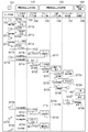
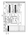
- 10A to 10C are diagrams for explaining the configuration of the screen for creating the submitted data used by the ordering party in the information processing device 110 in the ordering party system 109.
- FIG. 10A shows an example of an application screen for creating or editing a PDF which is image data to be submitted in the information processing device 110 in the ordering party system 109.
- the application of the present embodiment shows an example of an application in which the same application provides the functions of a plurality of target applications in parallel and is selectively used by the function tab. Therefore, the general-purpose function setting unit 1001, the PDF editing unit 1002, the PRX setting unit 1003, the JDF setting unit 1004, and the help function providing unit 1005 are switched and used. Each of these means is configured to be operable by selecting the corresponding tab.
- FIG. 10A shows an example of a screen in which the PDF edit setting unit 1002 is selected.
- the page selection unit 1006 is an area for selecting a page to be set when a print target product is composed of a plurality of pages and different quality requirements are set for each page.
- the first page (1007) shows the selected state. That is, an example of setting a quality requirement for the first page of the image data to be printed is shown.
- the thumbnail display area 1008 is a reference image display area for the user of the application shown in the figure to visually confirm the image information of the page selected by the page selection unit 1006 while performing various settings.
- the cash register mark 917 shown in FIG. 9C, the color patch 916, and the quality conditions required by the PRX described later are inspected by the printer system 100, and as a result, it corresponds to the additional image information required to generate the PQX.
- the cash register mark 917 is set by the cash register mark setting unit 1013.
- the registration mark setting unit 1013 instructs to add the registration mark to the image
- the registration mark 917 is added to the setting target page of the PDF file.
- the color patch 916 can be added to the PDF file setting target page by the color patch setting unit 1012.
- the registration mark detailed setting unit 1015 and the color patch detailed setting unit 1014 are setting units for setting detailed information such as the position when the color patch 916 and the registration mark 917 are added to the image. For example, if these registration marks 917 and color patches 916 are superimposed on the area of the image information 915 of the PDF, the original image cannot be obtained, which causes inconvenience. Therefore, the application in the present embodiment is possible so that the coordinates of the image position can be adjusted by these means so that the positions of the color patch 916 and the registration mark 917 do not overlap with the area of the image information 915 of the PDF.
- Objects 931 and 923,933 are objects having ID values of "50 obj", “70 obj", and "30 obj", respectively.
- the ID of the object is a unique value given automatically by the application that creates the PDF or by the user.
- the object ID is a value that does not change depending on the position of the object in the PDF. Therefore, when the object ID is specified in the PRX inspection position specification described later, it is not necessary to specify the inspection position again even if the object position is edited after the setting.
- the object context menu 934 is a menu of operations for an object that is displayed when a right-click operation is performed while the object is selected.
- the object context menu 934 includes an inspection setting button for specifying an inspection position for the ID of the selected object. When the inspection setting button is selected, the reference value of the ID of the selected object is added to the object selection unit 1042 of the PRX setting unit 1003 described later.
- the output intent setting unit 1009 is an output intent information setting unit realized by the PDF editing function. It is composed of an image forming process information setting unit 1010 used by an image forming means applied at the time of production, and a color intent setting unit 1011 applied to an image to be produced. By combining these output intent information with the page selection unit 1006, individual settings can be made for each page.
- FIG. 10B shows an example of an application screen for creating or editing PRX, which is quality requirement data to be submitted, in the information processing device 110 in the ordering party system 109.
- PRX setting unit 1003 By selecting the PRX setting unit 1003, the screen shown in the figure is displayed.
- the master information setting unit 1020 is a setting unit for inputting various master information required when creating a PRX.
- the master information corresponds to various information such as a date required by the PRX specifications, company information, and a name given to the required specifications specified by the PRX. These information can be edited by pressing the master information editing unit 1021.
- Comprehensive quality target setting unit 1022 is a setting unit for integrating at least one or more different types of quality requirements specified by PRX and defining an overall quality level. Overall quality is determined by the following regulations. That is, a combination of label 1023, which is readable information given to the quality level, rank 1024, which is quantitative numerical information corresponding to label 1023, and a value 1025, which defines parameters and mathematical formulas for determining rank 1024. Defined from.
- the highest quality 1031 will be used as an example, and details will be described below.
- the label of the highest quality 1031 is defined as "Excellent".
- the character string applied to these labels 1023 can be arbitrarily set by the user 701 who uses the application shown in the figure running on the information processing apparatus 110 in the orderer system 109, that is, the orderer. In other words, the information is provided so that the operator can easily determine the meaning of the defined quality level, and has properties different from the information used for control and the like.
- rank 1024 of the highest quality 1031 is defined as 10. This is a numerical value specified by the orderer in order to discriminate and manage the quality of the product requested by the orderer from the printing company to the quantitative enemy, and is information intended to be used for control and the like. However, the numerical value of rank 1024 itself can be arbitrarily specified by the orderer as a quantitative numerical value of the quality of his / her own product.
- the figure shows an example in which the value 1025 for defining the rank 1024 of the highest quality 1031 is "GT 8". If the numerical value of the quantitative quality index obtained by the specified evaluation formula is 8 or more, the rank 1024 of the highest quality 1031 is calculated to be 10, and the quality of the product is determined to be the highest quality. To.
- each quality level adopts a configuration in which information defined by the quality level editing unit 1026 can be edited.
- the number of quality levels can be set arbitrarily. That is, when specifying a fine level as needed, it is possible to press the level addition unit 1028 to add a new quality level to the comprehensive quality target setting unit 1022.
- the level deletion unit 1027 can delete the level with the checker.
- the acceptance conditions are specified by the numerical value of rank 1024 specified by the quality level for the quality of the produced product. Acceptance conditions are defined by the minimum acceptance quality setting unit 1029 and the required quality setting unit 1030.
- the minimum acceptable quality setting unit 1029 is for the ordering party to specify the acceptable quality, that is, the minimum value of rank 1024, when the deliverable is delivered to the printing company. In other words, inform the printing company of the quality requirements that the numerical value specified in the minimum acceptance quality setting unit 1029, and in the example of the figure, the product with the numerical value of rank 1024 lower than 8 does not meet the acceptance quality. Can be done.
- the requested quality setting unit 1030 defines the quality conditions requested by the ordering party when the deliverable is delivered to the printing company, that is, the requested value of rank 1024.
- the product of the numerical value specified in the requested quality setting unit 1030, or the numerical value of rank 1024 exceeding 9 in the example of the figure, can be transmitted to the printing company as a quality requirement.
- the image misalignment quality setting unit 1035 also defines the acceptance conditions for the image misalignment quality of the product by the numerical value of rank 1024 defined by the above-mentioned quality level when making a quality request regarding the image misalignment. Acceptance conditions are defined by the minimum accepted image misalignment quality setting unit 1037 and the desired image misalignment quality setting unit 1038 regarding the image misalignment quality.
- the image misalignment quality setting unit 1035 is a setting unit for inputting quality requirement information regarding the image misalignment of the deliverable when creating the PRX. Similar to the comprehensive quality target setting unit 1022, the label 1023 and the rank 1024 are set so that the level of the quality requirement regarding the image misalignment can be specified.
- the image misalignment quality value 1036 is defined based on the amount of misalignment (length or distance between the reference image and the image of the product) from the reference position, which is the measurement result of the product with respect to the required image misalignment. That is, an example is shown in which the highest quality 1039 in the image misalignment quality has a misalignment amount of 0.002 mm or less. That is, the figure shows an example in which the label 1023 in the case of the highest quality 1039 is "Excellent" and the rank is 10. Similarly, the figure shows an example in which "good product" 1040, "", and "failed quality” 1041 in the image misalignment quality are similarly defined. For the rank addition and deletion functions, the comprehensive quality target setting unit 1022 The explanation is omitted because it is realized by the same mechanism as.
- the minimum accepted image misalignment quality setting unit 1037 is a setting unit that defines the acceptable image misalignment quality, that is, the minimum value of rank 1024, when the orderer delivers the deliverable to the printing company.
- the image misalignment quality requirement that the product of the numerical value specified in the minimum accepted image misalignment quality setting unit 1037 and the numerical value of rank 1024 lower than 5 in the example of the figure does not satisfy the accepted image misalignment quality. Can be communicated to the printer.
- the requested image misalignment quality setting unit 1038 is a setting unit that defines the desired image misalignment quality condition, that is, the minimum value of rank 1024, when the orderer delivers the deliverable to the printing company. It is possible to convey the image misalignment quality requirement to the printing company with the product of the numerical value specified in the desired image misalignment quality setting unit 1038, that is, the numerical value of rank 1024 exceeding 10 in the example of the figure.
- the object selection unit 1042 is an area for displaying a button for selecting an object to be designated as an inspection position.
- the object selection unit 1042 displays the reference value of the ID of the object for which the inspection setting button is selected in the object context menu 934.
- the figure shows a state in which the "50 R" button 1043, which is a button corresponding to the reference value of "50 obj", is selected.
- the display may be switched to the same screen when the inspection setting button is selected.
- the color inspection is taken up in the description of the embodiment, it may be used to specify an inspection position other than the color.
- the target image display area 1044 is an area for displaying the image of the object selected by the object selection unit 1042.
- the reference data selection button 1045 is a button for selecting reference data to be compared in order to evaluate the inspection result of the object selected by the object selection unit 1042. For color inspection, select color reference data.
- the reference data selection button 1045 can be selected only when the button corresponding to the reference value of any object is selected in the object selection unit 1042.
- a file selection screen (not shown) is displayed, and a file can be selected.
- the color quality setting unit 1046 is a setting unit for inputting quality requirement information regarding the color of the product when creating the PRX. Similar to the comprehensive quality target setting unit 1022, the label 1023 and the rank 1024 are set so that the level of the quality requirement for color can be specified.
- the color quality value 1047 is defined based on the color difference (also called ⁇ E or delta E) of the color value which is the color measurement result of the product with respect to the required color. That is, the highest quality 1048 in color quality shows an example in which the color difference is 1.0 or less. That is, the figure shows an example in which the label 1023 in the case of the highest quality 1048 is "Excellent” and the rank is 10. Similarly, the figure shows an example in which "good product” 1049, "acceptable” 1050, and "failed quality” 1051 in color quality are similarly defined. The rank addition and deletion functions are realized by the same mechanism as the comprehensive quality target setting unit 1022.
- the acceptance condition is based on the numerical value of rank 1024 defined by the above-mentioned quality level for the color quality of the produced product.
- Acceptance conditions are defined by the minimum acceptance color quality setting unit 1053 and the desired color quality setting unit 1054 regarding color quality.
- the minimum acceptable color quality setting unit 1053 is for the orderer to specify the acceptable color quality, that is, the minimum value of rank 1024, when the deliverable is delivered to the printing company. In other words, as a color quality requirement, the printer is informed that the product of the numerical value specified in the minimum acceptable color quality setting unit 1053, and the numerical value of rank 1024, which is lower than 8 in the example of the figure, does not satisfy the accepted color quality. Can be communicated.
- the requested color quality setting unit 1054 is for defining the desired color quality condition, that is, the minimum value of rank 1024, when the orderer delivers the deliverable to the printing company.
- the color quality requirement can be transmitted to the printing company as a product of the numerical value specified in the desired color quality setting unit 1054, that is, the numerical value of rank 1024 exceeding 10 in the example of the figure.
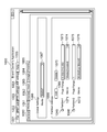
- FIG. 10C shows an example of an application screen for creating or editing a job ticket, that is, JDF data, which is print setting information to be submitted in the information processing device 110 in the ordering party system 109.
- JDF data which is print setting information to be submitted in the information processing device 110 in the ordering party system 109.
- the system in this embodiment is configured so that the JDF setting unit 1004 can select more detailed setting items as shown in the figure. That is, for each function to be set, there are a general setting unit 1060, a media setting unit 1061, an imposition setting unit 1062, an insert paper setting unit 1063, an image processing setting unit 1064, a post-processing processing setting unit 1065, and the like.
- the screen example shown in the figure shows an example of the display state of the screen when the media setting unit 1061 is selected.
- the job-wide media setting unit 1066 is composed of a job-wide media setting unit 1066 and a job partial media setting unit 1068.
- the entire job media setting unit 1066 is provided for selecting the media to be used in the job. That is, in the example shown in the figure, the state in which "Media1" is selected in the job-wide media type selection unit 1067 is shown. In other words, it means that the medium used at the time of printing is set to be "Media1" in the execution of the printing process by this JDF.
- the job partial media setting unit 1068 is a setting means used when setting media different from the media set by the job-wide media setting unit 1066 for a specific page or page range.
- the page range addition unit 1069 to be set, the check box 1046, and the page range erasing unit 1070 are used to create and delete the page range to be set by the job partial media setting unit 1068. provide.
- the figure shows the state where two page ranges have been created.
- the first page range setting unit 1071 5 pages, 200 pages to 210 pages, and 250 pages are set targets for the first page range 1073.
- an example is shown in which "Media2 (coated)" is used in the first partial media selection unit 1074 as the media used for the page to be set.
- one page is set as the setting target for the second page range 1075, and the media used for the page to be set is set to "Media3 (cardboard)" in the second partial media selection unit 1076.
- Media3 cardboard
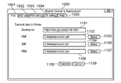
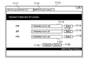
- 11A and 11B are examples of application screens when the information processing device 110 in the ordering party system 109 executes a process of uploading PRX, JDF, and PDF, which are quality requirement data to be submitted, to the printer system 100. Is shown.
- FIG. 11A shows an example of the screen 1000 in the case where the function of transmitting the submitted data to the printing company system 100 is provided as a part of the functions of the applications shown in FIGS. 10A to 10C. That is, when the general-purpose function setting unit 1001 is selected, the screen shown in the figure is displayed.
- the destination information setting unit 1101 is a designation unit that specifies the address of the web service provided as the submission means by the web server 504 running on the information processing device 102 in the printing company system 100.
- the first PDF file selection unit 1102 and the first PDF file selection instruction unit 1103 are both selection units that select a PDF file that is image data to be submitted from the file system provided in the information processing device 110 in the orderer system 109. is there.
- the first JDF file selection unit 1104 and the first JDF file selection instruction unit 1105 are selection units that select the JDF file, which is the job setting data to be submitted, from the file system provided in the information processing device 110 in the orderer system 109. is there.
- the first PRX file selection unit 1106 and the first PRX file selection instruction unit 1107 are selection units that select the PRX file, which is the quality request data to be submitted, from the file system provided in the information processing device 110 in the orderer system 109.
- the first processing stop instruction unit 1109 is an instruction unit for canceling the submission processing itself.
- FIG. 11B is for explaining the display state of the screen when the function equivalent to the submission instruction means by the application shown in FIG. 11A is provided by the operation means by the web browser.
- the destination information is input to the address input unit 1111 of the web browser to access the address of the web service provided by the web server 504 running on the information processing device 102 in the printing company system 100 as a submission means.
- the state transitions to the state of the submission web screen as shown in the figure (1110, 1112).
- a selection means having a function equivalent to each file selection means shown in FIG. 11A is provided as a screen of a web browser. That is, the second PDF file selection unit 1113 and the second PDF file selection instruction unit 1114 correspond to the functions of the first PDF file selection unit 1102 and the first PDF file selection instruction unit 1103.
- the second JDF file selection unit 1115 and the second JDF file selection instruction unit 1116 correspond to the functions of the first JDF file selection unit 1104 and the first JDF file selection instruction unit 1105.
- the second PRX file selection unit 1117 and the second PRX file selection instruction unit 1118 correspond to the functions of the first PRX file selection unit 1106 and the first PRX file selection instruction unit 1107.
- the second transmission instruction unit 1119 corresponds to the function of the first transmission instruction unit 1108, and the second processing stop instruction unit 1120 corresponds to the function of the first processing stop instruction unit 1109.
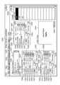
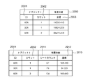
- 12A to 12D are for showing examples of various data to be submitted as a result of the operation by the ordering party using the operation means shown in FIGS. 10A to 10C. Details will be described below for each data type.
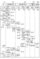
- FIG. 12A shows FIG. 10C, that is, a JDF format job ticket generated by means for creating or editing JDF data which is job ticket which is print setting information to be submitted in the information processing apparatus 110 in the ordering system 109.
- JDF format job ticket generated by means for creating or editing JDF data which is job ticket which is print setting information to be submitted in the information processing apparatus 110 in the ordering system 109. This is an example.
- the job ticket contains the following information. That is, the number of pages included in the section (1201), the job-wide print parameter 1202, and the job partial print parameter (1206, 1208).
- the job-wide print parameter 1202 includes the total number of copies printed 1203 and the media setting 1204 used for the entire job.
- the job partial print parameter (1206, 1208) includes page range information (1205, 1209) designated as a portion and media settings (1207, 1210) used in the portion.
- the actual settings of the media settings 1204 used for the entire job and the media settings (1207, 1210) used for the job part are specified in the media tags (1211, 1214, 1217).
- the media tag (1211, 1214, 1217) further includes setting information such as a media type (1213, 1216, 1219) and a media size (1212, 1215, 1218).
- FIG. 12B is an example of PRX data generated by FIG. 10B, that is, a means for creating or editing PRX which is quality requirement data to be submitted in the information processing device 110 in the ordering system 109.
- the PRX data includes the following information. That is, the master information 1220 and the comprehensive quality target setting information 1221.
- Comprehensive quality target setting information 1221 further includes regulation parts (1222, 1223, 1224, 1225) of each quality level, minimum accepted quality setting information 1226, required quality setting information 1227, and the like. The meaning of the information equivalent to these is omitted because it is given in the explanation of FIG. 10B.
- the color quality information regulation unit 1228 is composed of information for storing various setting information regarding the color quality of the product. Further, the color quality information regulation unit 1228 is composed of a part of a color quality evaluation regulation unit 1229 for storing information related to color quality evaluation and a part of a color quality measurement regulation unit 1239 for storing information related to measurement.
- the color quality information regulation unit 1228 includes a unit information regulation unit 1231 for defining a color difference which is a color quality, a regulation unit for each color quality level (1233, 1234, 1235, 1236), and the like. It also includes the minimum accepted color quality setting information 1237, the desired color quality setting information 1238, and the like. The meaning of the information equivalent to these is omitted because it is given in the explanation of FIG. 10B.
- the color quality measurement regulation unit 1239 is composed of a color measurement position regulation unit 1240 that defines a color measurement position and a reference color data regulation unit 1241 that compares the color measurement results.
- the reference color detailed information defining unit 1242 is provided to specify the reference data (correct answer value, reference value) requested as the color quality.
- Specific examples of the present embodiment include a CXF information defining unit 1243 and a spectroscopic spectrum information storage unit 1244, which is one of the means for expressing color information.
- the color measurement position data defining unit 1245 is a portion referred to by the color measurement position defining unit 1240, and is used to specify the color measurement position in image data.
- the color measurement position is specified by the ID of the object in the PDF file.
- the color measurement position designation 1246 having a value of "CL1" in Id specifies an object whose ID in the PDF is "60 R" as the color measurement position.
- FIG. 12C is for explaining an example of the inspection result when the inspection unit 214 included in the image forming devices 103 and 104 inspects the image information formed on the sheet which is the product.
- the information shown in the figure is created by the controller unit 205 executing the inspection program 410 included in the image forming apparatus 104, and is transmitted to the workflow control program 505 operating on the information processing apparatus 102.
- the information included in the inspection result data will be described below.
- the inspection execution object ID 1261 is provided for the purpose of storing the object ID information of the target for which the inspection was performed when the inspection unit 214 performed the inspection, and the object ID of the PDF is stored. As described above, in FIG. 10A, the inspection setting button is selected from the object context menu 934, and the object to which the reference value of the object ID is added to the object selection unit 1042 in FIG. 10B is the measurement target.
- the inspection execution object count 1262 stores the number of objects having the ID stored in the inspection execution object ID 1261 that the inspection was performed when the inspection unit 214 performed the inspection. Since the object ID is a unique value, it does not overlap within the same PDF, but it is used to distinguish which print measurement result is used when printing multiple times from the same PDF by printing multiple copies or multi-imposition printing. To do. The flow of processing related to the creation of the values of the inspection execution object ID 1261 and the inspection execution object count 1262 will be described with reference to FIG.
- the spectral spectrum data 1263 is numerical data of the spectral spectrum which is the color information of the image on the sheet by the third inspection unit 912 and the fourth inspection unit 913 shown in FIGS. 9A to 9C in the inspection unit 214. .. It is stored in PQX data, which will be described later, and is used to provide the orderer with inspection results regarding color quality.
- FIG. 12D shows an example of print quality report data, that is, PQX data, which is created by receiving the inspection information shown in FIG. 12C by the workflow control program 505.
- PQX data which is created by receiving the inspection information shown in FIG. 12C by the workflow control program 505.
- the main information contained in PQX will be described.
- the PQX header information 1267 is a storage area for the main information that the PQX data should hold.
- the work report storage unit 1268 is used to store the quality inspection result performed when the image forming devices 103 and 104 execute the process and general-purpose information associated with the quality inspection result.
- the inspection result storage area 1272 is a storage unit provided for the purpose of identifying and storing various inspection results related to the quality of product creation carried out by the inspection unit 214 for each type of inspection.
- the color quality report storage unit 1273 is an area for storing report information related to color information among the quality report information provided by the printing company to the ordering party, including the PQX. Information on the region is created based on the spectroscopic spectrum data 1264 shown in FIG. 12C. That is, the reference link 1274 of the spectroscopic spectrum data 1264, the spectroscopic spectrum data storage unit 1276 of the implementation referred to by the reference link 1274, the spectroscopic spectrum data 1278, and the measurement position designation unit 1275 correspond to this.
- the data stored in the spectroscopic spectrum data storage unit 1276 from the PQX received by the third reception program 609 and the color quality information regulation unit 1229 transmitted as PRX by the third transmission program 608 are compared, and the color difference (delta E) is compared. ) Is calculated. Then, the process of deriving the rank 1024 from the value 1037 defined by the color quality setting unit 1036 in FIG. 10B is performed, and it is used to derive the discrimination information regarding the color quality.
- the measurement position designation unit 1275 is a part for indicating the color measurement position by the ID of the object. It is a reference link, and the actual object information indicating the color measurement position is stored in the color measurement position data 1280 in which the reference link and the Id in the color measurement position designation image data 1279 match.
- the color measurement position data 1280 stores the ID and count value of the color measurement object created from the inspection execution object ID 1261 and the inspection execution object count 1262 shown in FIG. 12C.
- the data stored in the image misalignment quality report storage unit 1278 from the PQX received by the third reception program 609 and the image misalignment quality information regulation unit 1241 transmitted as PRX by the third transmission program 608 are compared. Calculate the amount of deviation. Then, the process of deriving the rank 1024 from the value 1048 defined by the image misalignment quality setting unit 1047 in FIG. 10B is performed, and it is used to derive the discrimination information regarding the image misalignment quality.
- FIG. 13 is a flowchart showing the processing flow of the controller unit 205 when the job generation instruction is received in S726. Partially overlaps with the description of FIG. Here, the method of determining the inspection position of the quality requirement whose color measurement position is specified by the object ID in the PRX data of FIG. 12B will be mainly described.
- the controller unit 205 receives data related to job processing from the workflow control program 505.
- the data related to job processing includes JDF of print settings, quality measurement parameters obtained by analyzing PRX (including inspection instruction information) of quality requirements, PDF to be printed, and the like.
- PRX including inspection instruction information
- the controller unit 205 analyzes the JDF received in S1301. The analysis of JDF was explained in the JDF function program 406 of FIG. After analyzing the JDF, proceed to S1303.
- the controller unit 205 analyzes the PDF received in S1301.
- the analysis of PDF was described in the PDF function program 407 of FIG. Rasterization and imposition are performed in the PDF analysis process, and the data is converted into image data used for printing. At this time, the position where each object of PDF is printed is determined.
- the process proceeds to S1304.
- the controller unit 205 determines whether the inspection position is specified by the object ID (object identification information) or the coordinates (coordinate information) in the quality measurement parameter received in S1301. The process is switched based on the judgment result. If the inspection position is specified by the object ID, the process proceeds to S1306, and if the inspection position is specified by the coordinates, the process proceeds to S1313.
- 22A and 22B are examples of PRX (quality requirement data).
- FIG. 22A is an example of PRX in which the object is designated.
- 2201 represents the object ID.
- FIG. 22B is an example of PRX whose coordinates are specified.
- 2202 represents the coordinates of the inspection position.
- the example of PRX is an example, and the designation of the inspection position may be another description.
- the controller unit 205 calculates the point on the object as the inspection position from the imposition acquired by the JDF analysis, the object ID acquired by the PDF analysis, and the PDF coordinates of the object. The calculation of the inspection position will be described with reference to FIGS. 21A and 21B. After calculation, proceed to S1307. In S1313, the controller unit 205 acquires the inspection position from the PRX.
- the controller unit 205 stores the print position of the object whose inspection position is specified by the object ID as the inspection position in the RAM 208.
- a schematic diagram of the data to be stored is shown in FIG.
- the controller unit 205 executes printing.
- the printing process has been described with reference to FIGS. 2, 4, 9A to 9C.
- the process proceeds to S1308.
- the controller unit 205 executes the inspection.
- the inspection process has been described with reference to FIGS. 2, 4, 9A to 9C.
- the inspection position the inspection position calculated in S1305 is used in the case of object designation, and the inspection position acquired in S1313 is used in the case of coordinate designation.
- the process proceeds to S1309.
- the controller unit 205 acquires the inspection position from the inspection result acquired in S1308 in S1309, and determines whether or not it matches the inspection position registered in S1306. That is, it is determined whether or not there is an object whose inspection position matches in the data table shown in FIG. If an object is specified, it is determined that there is an object. If there is an object, proceed to S1310, otherwise proceed to S1311.
- the controller unit 205 acquires the object ID and the count stored in association with the inspection position. After obtaining it, proceed to S1311.
- the controller unit 205 creates an inspection result using the object ID.
- the test results have been described with reference to FIG. 12C.
- the inspection execution object ID 1261 and the inspection execution object count 1262 are the object ID and count acquired in S1310, and the spectroscopic spectrum data 1263 is the inspection data acquired in S1308. After creating the inspection result, proceed to S1312. In S1314, the controller unit 205 creates an inspection result using the coordinates.
- the controller unit 205 transmits the inspection result to the information processing device 102.
- the transmission of the inspection result has been described in the first transmission program 405 of FIG. After sending the inspection result, end the flowchart.
- FIG. 20 is a schematic diagram of a data table in which the identification information of the object and the position where the object is printed, that is, the inspection position are associated and stored.
- the image is stored in the RAM 208 of the image forming apparatus 104.
- the continuous business sheet inspection position correspondence table 2000 is a table for storing the inspection position in the printing machine that handles the continuous business sheet in association with the identification information of the object.
- the object ID 2001 and the count 2002 indicating the number of times the object has been printed are stored as the object identification information, and the print position 2003 of the object on the continuous business sheet is stored as the inspection position.
- the cut sheet inspection position correspondence table 2010 is a table for storing the inspection position in the printing machine that handles the cut sheet in association with the identification information of the object.
- the object identification information is the same as in the case of the continuous book sheet, but the inspection position stores the sheet count 2011 indicating the number of sheets and the print position 2012 of the cut sheet-like object.
- the inspection unit 204 handles the position where the inspection is performed according to the position on the printed matter.
- the inspection result is transmitted to the information processing apparatus 102, it becomes object identification information as shown in FIG. 12C.
- the inspection position is converted into the identification information of the object, and the ID which is the identification information of the object and the count which is the number of prints are counted. get.
- FIG. 21A and 21B are diagrams for explaining an example of the process of calculating the inspection position corresponding to the object ID.
- FIG. 21A shows an example in which imposition is performed on a paper having a size twice the PDF page size in 2 in 1
- FIG. 21B shows an example in which the PDF page size and the paper size are different and imposition is performed according to the paper size by scaling. There is.
- the coordinates (X, Y) of an arbitrary point 2102 on the PDF page 2101 are printed on the coordinates (X', Y) of the point 2104 on the paper.
- ') Is calculated by the coordinate conversion formula 2105. That is, in the case of even pages, the coordinates (X', Y') are the coordinates on the PDF as they are in the case of even pages, and in the case of even pages, the width of the PDF page, that is, the position shifted by half the width of the paper. ..
- the coordinates (X, Y) of arbitrary points 2102 on the PDF and the coordinates (X', Y') of the points 2104 on the printed paper are set by the ratio of the PDF page size to the paper size. Will be misaligned. Therefore, the coordinates (X', Y') of the points 2104 on the paper are calculated by the coordinate conversion formula 2106.
- the inspection position is described in coordinates, so when an object was specified, it was difficult to understand what was the measurement result. That is, even if the inspection target is the same, if the arrangement is different, it is described in PQX as a result for different coordinates, so that it is difficult to refer to the report.
- the quality report is also described in association with the identification information of the object to be inspected, so that it is easy to understand what the quality report is for.
- the image forming apparatus shown in the present embodiment makes it possible to specify the inspection position by the object ID of PDF, thereby eliminating the trouble of recreating the quality requirement even if the position of the object changes. ing. Further, the orderer can specify the inspection position by specifying the object ID or the coordinates, and further, the quality report data can be acquired by the description method corresponding to the designation, so that the confirmation can be easily performed. By storing and notifying the quality measurement result specified by the object ID in association with the object ID, it becomes possible to easily know which object the inspection result is measured.
- FIG. 14 is a system flow diagram in the second embodiment. The same configuration number is described in the same configuration as in the configuration of FIG. 1 and the process of FIG. 7.
- the inspection device 1401 is an offline inspection device, that is, an independent inspection device that is not connected to the image forming device 104.
- the information processing device 102 is connected to the information processing device 102 via a network and an inspection instruction can be given from the workflow control unit 707. It may be configured to give an inspection instruction using a bar code or the like without being connected to the information processing device 102.
- the inspection control unit 1402 is a part that controls the operation of the inspection device 1401.
- the workflow control unit 707 generates a print job for the print control unit 708 that forms a component of the image forming apparatus 104. This print job does not include performing an inspection.
- the print control unit 708 starts the print process.
- the table storing the correspondence between the identification information of the object created at the time of analyzing the PDF data and the printing position, that is, the information corresponding to FIG. 20 is transmitted to the information processing apparatus 102.
- the information processing device 102 stores data in the RAM 302.
- the print control unit 708 gives an inspection instruction to the inspection control unit 1402.
- the inspection position specified by the ID of the object in the quality request is converted into the inspection position which is the coordinates on the printed matter by referring to the data stored in the RAM 302 in S1404, that is, the data shown in FIG.
- the inspection position obtained by this conversion is used for the inspection instruction.
- the inspection control unit 1402 transmits the inspection result to the workflow control unit 707.
- the inspection result is created in association with the inspection position included in the inspection instruction received in S1405. This will be described with reference to FIG.
- the print control unit 708 converts the inspection position included in the inspection result received in S1406 into object identification information by referring to the data stored in the RAM 302 in S1404, that is, the data shown in FIG.
- the print quality report data shown in FIG. 12D is created using the obtained object IDs and counts.
- FIG. 15 is an example of the inspection result created by the inspection control unit 1402 in S1406 and transmitted to the workflow control unit 707.
- the same numbers are shown in the same places as those in FIGS. 12A to 12D.
- the continuous business sheet inspection result 1500 shows an example of the inspection result for the continuous business sheet.
- the continuous line sheet inspection position 1501 represents the inspection position where the inspection was performed by the coordinates on the printed matter.
- the inspection position corresponding to the coordinates shown here is stored in the continuous line sheet inspection position correspondence table 2000, it indicates that the inspection position is the result for the inspection specified by the object ID in the quality requirement.
- Cut sheet inspection result 1510 shows an example of the inspection result for the cut sheet.
- the sheet count 1511 is a value indicating the sheet on which the inspection was carried out
- the cut sheet inspection position 1512 is the inspection position on which the inspection was carried out expressed in coordinates on the printed matter.
- the workflow control unit 707 corresponds the identifier of the object specified as the inspection position in the quality request with the inspection position on the printed matter. As a result, it is possible to specify the inspection position by the object ID even when the inspection is performed by the offline inspection device.
- the image forming apparatus 104 lips the PDF to create the correspondence between the object ID and the inspection position, but the third embodiment shows an embodiment in a configuration in which the lip processing is performed by the information processing apparatus 110. ..
- the third embodiment shows an embodiment in which it is not necessary to respecify an object even if the PDF is different.
- FIG. 16 is a schematic representation of the information stored in the HDD 311 or the RAM 302 by the information processing device 110.
- the object ID column 1601, the inspection content column 1602, the reference data column 1603, and the evaluation data column 1604 are the ID of the object to be inspected, the content of the inspection to be performed, and the file name of the data to be referred to for evaluating the inspection result.
- Evaluation data are labels, ranks, and values that serve as criteria for evaluation. In the line where the object ID of FIG. 16 is "5.0 R", color measurement is registered as inspection content, "corplogo.cxf" is registered as reference data, the label “Excellent” has a rank of 10 and a value of LT1.0 ... is registered as evaluation data. Has been done.
- the CPU 301 compares the object ID of the selected PDF with the object ID registered in FIG. Then, the inspection contents, reference data, and evaluation data recorded correspondingly are read out, and the PRX setting is automatically created.
- the registration of FIG. 16 may be performed on the screen of FIG. 10B, or may be performed on another screen on which equivalent settings can be made.
- FIG. 16 can also be used in combination with the first and second embodiments.
- FIG. 17 is a diagram illustrating a program of the image forming apparatus 104 in the present embodiment.
- the JDF analysis and the PDF analysis are performed by the workflow control program 505.
- the same parts as those in the first and second embodiments have the same numbers as those in FIG.
- the print job management program 1701 is a program for managing a series of processes from receiving a print job creation instruction to completing a print job. Similar to the JDF function program 406 in the first and second embodiments, it has a function of executing the JDF print function, but does not have a function related to the analysis process of the JDF job data. In this embodiment, since the JDF analysis is performed by the JDF function program 1801 of the information processing device 110, the image forming device 104 is notified of the print setting parameters after the analysis.
- the print image management program 1702 is a program for managing the image data to be printed.
- the image forming apparatus 104 is notified of the intermediate data after the analysis.
- the format of the intermediate data depends on the image forming apparatus 104, but it is assumed that the intermediate data shown in the present embodiment is a state after the print position of the PDF object is obtained.
- FIG. 18 is a diagram illustrating a program of the information processing device 110 according to the present embodiment.
- the same parts as those in the first and second embodiments have the same numbers as those in FIG.
- the JDF function program 1801 analyzes the JDF job data, determines whether or not the JDF contains incorrect settings as a result of the analysis processing, and changes the settings to eliminate the incorrect settings. It is a program to do.
- the PDF function program 1802 is a program that expands PDF data.
- the PDF function program 1802 creates a correspondence between the object ID and the position of the object on the printed matter from the PDF analysis result, that is, the table shown in FIG. 20, and stores it in the RAM 302.
- the workflow control program 505 notifies the image forming apparatus 104 of the inspection position. Specifically, among the PRXs analyzed by the quality request receiving program 507, those whose inspection position is specified by the object ID are converted into the inspection positions on the printed matter obtained as a result of the analysis of the PDF function program 1802. Notify. Further, when the inspection result indicated by the coordinates obtained by the inspection of FIG. 15 is received in S728 or S1406, the coordinates are returned to the object identification information by using the analysis result of the PDF function program 1802 again, and the PQX of FIG. 12D is used. To create.
- FIG. 19 is a flow of processing performed by the CPU 301 of the information processing device 110 from the reception of the order by the information processing device 110 in S719 to the creation of the report in S728.
- this implementation system can be implemented with an offline inspection device, an example of an in-line inspection device is described here.
- the CPU 301 receives order-related data.
- Order-related data includes JDF for print settings, PRX for quality requirements, PDF to be printed, and the like.
- the process proceeds to S1902.
- the CPU 301 analyzes the JDF with the JDF function program 1801, links the analysis result with the job identification information, and stores it in the RAM 302. After memorizing, proceed to S1903.
- the CPU 301 analyzes the PRX (quality request data) with the quality request reception program 507, associates the analysis result with the job identification information, and stores it in the RAM 302. After memorizing, proceed to S1904.
- the CPU 301 analyzes the PDF data with the PDF function program 1802, associates the analysis result with the job identification information, and stores it in the RAM 302 or the HDD 311. After memorizing, proceed to S1905.
- the CPU 301 determines whether the quality measurement position is specified by the object ID or the coordinates in the PRX analyzed in S1903. If the quality measurement position is specified by the object ID, the process proceeds to S1907, and if the quality measurement position is specified by the coordinates, the process proceeds to S1913.
- the CPU 301 calculates a point on the object as an inspection position from the imposition acquired by the JDF analysis, the object ID acquired by the PDF analysis, and the PDF coordinates of the object. The calculation of the inspection position will be described with reference to FIGS. 21A and 21B. After calculation, proceed to S1907.
- the CPU 301 stores the print position of the object calculated in S1907 in the RAM 302 or the HDD 311 in association with the object ID. After memorizing, proceed to S1907.
- the CPU 301 acquires the inspection position from the PRX analyzed in S1904.
- the CPU 301 gives a print instruction to the image forming apparatus 104, and transmits the JDF analysis result, the PDF analysis result, and the PRX analysis result.
- the inspection position is specified by the inspection position on the printed matter acquired in S1907.
- the inspection device is an offline device, it is not necessary to transmit the PRX analysis result.
- the CPU 301 finishes printing and inspection in the image forming apparatus 104, and receives the inspection result of FIG. 15 together with the information for identifying the job.
- the inspection result is expressed using the coordinates of the inspection position.
- the test results are described in FIG. If the inspection device is an offline device, only the completion of printing is notified here, and when the notification is received, the PRX analysis result is transmitted to the inspection device. It waits until the inspection result is received from the inspection device, and the subsequent processing is the same as in the case of the in-line device.
- the CPU 301 determines whether there is an object corresponding to the inspection position described in the inspection result received in S1909.
- the table shown in FIG. 20 stored in the RAM 302 is used for the determination. If there is an object, the process proceeds to S1911, and if there is no object, the process proceeds to S1912.
- the CPU 301 acquires the identification information of the object corresponding to the inspection position on the printed matter. After acquiring the object identification information, the process proceeds to S1912.
- the CPU 301 creates a report. This report is the PQX described in FIG. 12D. If it is specified by the object ID, the inspection result report is created by using the object identification information acquired in S1911. If it is specified by coordinates, a report of inspection results using coordinates received in S1909 is created.
- the system shown in the present embodiment makes it possible to specify the inspection position by the object ID even in the configuration in which the information processing device 110 performs lip processing.
- the quality inspection can be executed without resetting the quality inspection setting even if the PDF is different.
- the present invention supplies a program that realizes one or more functions of the above-described embodiment to a system or device via a network or storage medium, and one or more processors in the computer of the system or device reads and executes the program. It can also be realized by the processing to be performed. It can also be realized by a circuit (for example, ASIC) that realizes one or more functions.
- a circuit for example, ASIC
- the quality requirement is specified by the identifier of the object to be inspected, it is not necessary to respecify the inspection position even if the arrangement of the inspection target is changed. Furthermore, since the quality report is described in association with the identifier of the object to be inspected, it is easy to understand what the quality report is for. In this way, quality requirements and quality reports can be made accessible.
Landscapes
- Engineering & Computer Science (AREA)
- Theoretical Computer Science (AREA)
- Human Computer Interaction (AREA)
- Physics & Mathematics (AREA)
- General Engineering & Computer Science (AREA)
- General Physics & Mathematics (AREA)
- Quality & Reliability (AREA)
- Accessory Devices And Overall Control Thereof (AREA)
- Inking, Control Or Cleaning Of Printing Machines (AREA)
Priority Applications (3)
| Application Number | Priority Date | Filing Date | Title |
|---|---|---|---|
| CN202080056050.5A CN114269565A (zh) | 2019-08-07 | 2020-07-16 | 信息处理装置及其控制方法 |
| EP20850939.8A EP4011635A4 (en) | 2019-08-07 | 2020-07-16 | INFORMATION PROCESSOR AND CONTROL METHOD THEREOF |
| US17/665,273 US11836398B2 (en) | 2019-08-07 | 2022-02-04 | Information processing apparatus and control method therefor |
Applications Claiming Priority (2)
| Application Number | Priority Date | Filing Date | Title |
|---|---|---|---|
| JP2019145575A JP7433802B2 (ja) | 2019-08-07 | 2019-08-07 | 情報処理装置及びその制御方法 |
| JP2019-145575 | 2019-08-07 |
Related Child Applications (1)
| Application Number | Title | Priority Date | Filing Date |
|---|---|---|---|
| US17/665,273 Continuation US11836398B2 (en) | 2019-08-07 | 2022-02-04 | Information processing apparatus and control method therefor |
Publications (1)
| Publication Number | Publication Date |
|---|---|
| WO2021024733A1 true WO2021024733A1 (ja) | 2021-02-11 |
Family
ID=74504092
Family Applications (1)
| Application Number | Title | Priority Date | Filing Date |
|---|---|---|---|
| PCT/JP2020/027601 Ceased WO2021024733A1 (ja) | 2019-08-07 | 2020-07-16 | 情報処理装置及びその制御方法 |
Country Status (5)
| Country | Link |
|---|---|
| US (1) | US11836398B2 (enExample) |
| EP (1) | EP4011635A4 (enExample) |
| JP (1) | JP7433802B2 (enExample) |
| CN (1) | CN114269565A (enExample) |
| WO (1) | WO2021024733A1 (enExample) |
Cited By (3)
| Publication number | Priority date | Publication date | Assignee | Title |
|---|---|---|---|---|
| EP4099242A1 (en) * | 2021-06-02 | 2022-12-07 | Canon Kabushiki Kaisha | Order management system, order management method, and program |
| EP4161048A1 (en) * | 2021-09-30 | 2023-04-05 | Canon Kabushiki Kaisha | System, information processing apparatus, and control method of the same |
| US12058298B2 (en) | 2021-09-30 | 2024-08-06 | Canon Kabushiki Kaisha | Information processing apparatus and control method of the same for color validation |
Families Citing this family (2)
| Publication number | Priority date | Publication date | Assignee | Title |
|---|---|---|---|---|
| JP2022187834A (ja) * | 2021-06-08 | 2022-12-20 | キヤノン株式会社 | 印刷制御システム、印刷制御方法、印刷制御装置とプログラム |
| JP2025029953A (ja) * | 2023-08-22 | 2025-03-07 | 富士フイルムビジネスイノベーション株式会社 | 画像検査システム、情報処理装置およびプログラム |
Citations (6)
| Publication number | Priority date | Publication date | Assignee | Title |
|---|---|---|---|---|
| JP2004351814A (ja) | 2003-05-30 | 2004-12-16 | Dainippon Screen Mfg Co Ltd | 色調制御装置および代表点決定方法 |
| JP2012206461A (ja) * | 2011-03-30 | 2012-10-25 | Canon Inc | 制御装置、検品処理の設定方法及びプログラム |
| WO2014108460A2 (en) * | 2013-01-14 | 2014-07-17 | Crest Solutions Limited | A label inspection system and method |
| JP2017191979A (ja) * | 2016-04-12 | 2017-10-19 | コニカミノルタ株式会社 | 画像形成システム、画像形成装置及びプログラム |
| JP2019145575A (ja) | 2018-02-16 | 2019-08-29 | 日東電工株式会社 | マスキング材 |
| JP2020006603A (ja) * | 2018-07-10 | 2020-01-16 | コニカミノルタ株式会社 | 画像検査システム、画像検査方法、および画像検査プログラム |
Family Cites Families (12)
| Publication number | Priority date | Publication date | Assignee | Title |
|---|---|---|---|---|
| US5768487A (en) * | 1995-10-31 | 1998-06-16 | Seiko Epson Corporation | System and method using a split printer driver to control a computer printer device |
| JP4592081B2 (ja) * | 2004-04-28 | 2010-12-01 | キヤノン株式会社 | 印刷スケジュール制御装置及び印刷スケジュール制御方法並びにプログラム |
| US7268896B2 (en) * | 2005-06-04 | 2007-09-11 | Bell Litho, Inc. | Method for controlling brand integrity in a network environment |
| JP4834387B2 (ja) * | 2005-11-28 | 2011-12-14 | キヤノン株式会社 | 画像形成装置及び画像形成方法 |
| CN101166220A (zh) * | 2006-10-20 | 2008-04-23 | 佳能株式会社 | 打印处理设备以及控制打印处理设备的方法 |
| JP5094504B2 (ja) * | 2008-03-28 | 2012-12-12 | 富士フイルム株式会社 | 画像形成装置 |
| DE102010054344A1 (de) * | 2010-12-13 | 2012-06-14 | Heidelberger Druckmaschinen Ag | System zur Erzeugung und Inspektion von Drucken mit statischen und variablen Inhalten |
| JP2013233772A (ja) * | 2012-05-11 | 2013-11-21 | Canon Inc | 検品システム、印刷装置、検品システムの制御方法、及びプログラム |
| JP5223995B1 (ja) * | 2012-11-28 | 2013-06-26 | 富士ゼロックス株式会社 | 印刷制御装置、データ管理方法およびプログラム |
| EP2778892B1 (en) * | 2013-03-11 | 2022-08-10 | Esko Software BV | Method and system for inspecting variable-data printing |
| JP6295561B2 (ja) * | 2013-09-17 | 2018-03-20 | 株式会社リコー | 画像検査結果判断装置、画像検査システム及び画像検査結果の判断方法 |
| JP6299203B2 (ja) * | 2013-12-17 | 2018-03-28 | 株式会社リコー | 印刷検査装置、印刷検査方法及び印刷検査プログラム |
-
2019
- 2019-08-07 JP JP2019145575A patent/JP7433802B2/ja active Active
-
2020
- 2020-07-16 CN CN202080056050.5A patent/CN114269565A/zh active Pending
- 2020-07-16 WO PCT/JP2020/027601 patent/WO2021024733A1/ja not_active Ceased
- 2020-07-16 EP EP20850939.8A patent/EP4011635A4/en not_active Withdrawn
-
2022
- 2022-02-04 US US17/665,273 patent/US11836398B2/en active Active
Patent Citations (6)
| Publication number | Priority date | Publication date | Assignee | Title |
|---|---|---|---|---|
| JP2004351814A (ja) | 2003-05-30 | 2004-12-16 | Dainippon Screen Mfg Co Ltd | 色調制御装置および代表点決定方法 |
| JP2012206461A (ja) * | 2011-03-30 | 2012-10-25 | Canon Inc | 制御装置、検品処理の設定方法及びプログラム |
| WO2014108460A2 (en) * | 2013-01-14 | 2014-07-17 | Crest Solutions Limited | A label inspection system and method |
| JP2017191979A (ja) * | 2016-04-12 | 2017-10-19 | コニカミノルタ株式会社 | 画像形成システム、画像形成装置及びプログラム |
| JP2019145575A (ja) | 2018-02-16 | 2019-08-29 | 日東電工株式会社 | マスキング材 |
| JP2020006603A (ja) * | 2018-07-10 | 2020-01-16 | コニカミノルタ株式会社 | 画像検査システム、画像検査方法、および画像検査プログラム |
Non-Patent Citations (1)
| Title |
|---|
| See also references of EP4011635A4 |
Cited By (5)
| Publication number | Priority date | Publication date | Assignee | Title |
|---|---|---|---|---|
| EP4099242A1 (en) * | 2021-06-02 | 2022-12-07 | Canon Kabushiki Kaisha | Order management system, order management method, and program |
| EP4161048A1 (en) * | 2021-09-30 | 2023-04-05 | Canon Kabushiki Kaisha | System, information processing apparatus, and control method of the same |
| US11956406B2 (en) | 2021-09-30 | 2024-04-09 | Canon Kabushiki Kaisha | System, information processing apparatus, and control method of the same preliminary class |
| US20240214505A1 (en) * | 2021-09-30 | 2024-06-27 | Canon Kabushiki Kaisha | System, information processing apparatus, and control method of the same |
| US12058298B2 (en) | 2021-09-30 | 2024-08-06 | Canon Kabushiki Kaisha | Information processing apparatus and control method of the same for color validation |
Also Published As
| Publication number | Publication date |
|---|---|
| EP4011635A1 (en) | 2022-06-15 |
| EP4011635A4 (en) | 2023-09-06 |
| CN114269565A (zh) | 2022-04-01 |
| US20220156020A1 (en) | 2022-05-19 |
| US11836398B2 (en) | 2023-12-05 |
| JP2021024223A (ja) | 2021-02-22 |
| JP7433802B2 (ja) | 2024-02-20 |
Similar Documents
| Publication | Publication Date | Title |
|---|---|---|
| JP7433802B2 (ja) | 情報処理装置及びその制御方法 | |
| US11336774B2 (en) | Information processing apparatus, method, and product comparing new and old versions of submitted data to specify inspection affected by difference | |
| CN113227960B (zh) | 信息处理装置、用于信息处理装置的控制方法、以及程序 | |
| JP7511339B2 (ja) | 情報処理装置、制御方法とプログラム | |
| JP7289716B2 (ja) | 情報処理装置、情報処理装置の制御方法、および、プログラム | |
| JP7493964B2 (ja) | ジョブ処理装置、制御方法、及びプログラム | |
| JP7337501B2 (ja) | 情報処理装置、情報処理装置の制御方法、及び、プログラム | |
| JP7407599B2 (ja) | 情報処理装置、情報処理装置の制御方法およびプログラムと検品システム及び検品システムの制御方法 | |
| US20220156019A1 (en) | Information processing apparatus and control method therefor | |
| JP2022032809A (ja) | 情報処理装置、印刷システム、データ構造、情報処理方法、印刷方法、及びプログラム | |
| JP7536524B2 (ja) | 情報処理装置、情報処理装置の制御方法、及びプログラム | |
| JP2021028797A (ja) | 情報処理装置、情報処理方法とプログラム | |
| JP7475819B2 (ja) | 印刷システム、印刷システムの制御方法、及び、プログラム | |
| JP7527876B2 (ja) | システム、情報処理装置及びその制御方法 | |
| JP2021089608A (ja) | ワークフローシステム、情報処理装置、画像形成装置、処理装置、画像処理装置の制御方法 | |
| JP7546424B2 (ja) | 生産制御装置及び生産方法とプログラム | |
| JP2023031709A (ja) | 情報処理装置及びその制御方法、印刷装置、並びにプログラム |
Legal Events
| Date | Code | Title | Description |
|---|---|---|---|
| 121 | Ep: the epo has been informed by wipo that ep was designated in this application |
Ref document number: 20850939 Country of ref document: EP Kind code of ref document: A1 |
|
| NENP | Non-entry into the national phase |
Ref country code: DE |
|
| ENP | Entry into the national phase |
Ref document number: 2020850939 Country of ref document: EP Effective date: 20220307 |