WO2021024684A1 - 園芸用トリマ - Google Patents
園芸用トリマ Download PDFInfo
- Publication number
- WO2021024684A1 WO2021024684A1 PCT/JP2020/026613 JP2020026613W WO2021024684A1 WO 2021024684 A1 WO2021024684 A1 WO 2021024684A1 JP 2020026613 W JP2020026613 W JP 2020026613W WO 2021024684 A1 WO2021024684 A1 WO 2021024684A1
- Authority
- WO
- WIPO (PCT)
- Prior art keywords
- cam member
- eccentric cam
- cam
- gravity
- rotation axis
- Prior art date
- Legal status (The legal status is an assumption and is not a legal conclusion. Google has not performed a legal analysis and makes no representation as to the accuracy of the status listed.)
- Ceased
Links
Images



Classifications
-
- A—HUMAN NECESSITIES
- A01—AGRICULTURE; FORESTRY; ANIMAL HUSBANDRY; HUNTING; TRAPPING; FISHING
- A01G—HORTICULTURE; CULTIVATION OF VEGETABLES, FLOWERS, RICE, FRUIT, VINES, HOPS OR SEAWEED; FORESTRY; WATERING
- A01G3/00—Cutting implements specially adapted for horticultural purposes; Delimbing standing trees
- A01G3/04—Apparatus for trimming hedges, e.g. hedge shears
- A01G3/047—Apparatus for trimming hedges, e.g. hedge shears portable
- A01G3/053—Apparatus for trimming hedges, e.g. hedge shears portable motor-driven
-
- A—HUMAN NECESSITIES
- A01—AGRICULTURE; FORESTRY; ANIMAL HUSBANDRY; HUNTING; TRAPPING; FISHING
- A01D—HARVESTING; MOWING
- A01D34/00—Mowers; Mowing apparatus of harvesters
- A01D34/01—Mowers; Mowing apparatus of harvesters characterised by features relating to the type of cutting apparatus
- A01D34/02—Mowers; Mowing apparatus of harvesters characterised by features relating to the type of cutting apparatus having reciprocating cutters
- A01D34/08—Mowers; Mowing apparatus of harvesters characterised by features relating to the type of cutting apparatus having reciprocating cutters hand-guided by a walking operator
- A01D34/10—Mowers; Mowing apparatus of harvesters characterised by features relating to the type of cutting apparatus having reciprocating cutters hand-guided by a walking operator with motor driven cutters or wheels
-
- A—HUMAN NECESSITIES
- A01—AGRICULTURE; FORESTRY; ANIMAL HUSBANDRY; HUNTING; TRAPPING; FISHING
- A01D—HARVESTING; MOWING
- A01D34/00—Mowers; Mowing apparatus of harvesters
- A01D34/01—Mowers; Mowing apparatus of harvesters characterised by features relating to the type of cutting apparatus
- A01D34/02—Mowers; Mowing apparatus of harvesters characterised by features relating to the type of cutting apparatus having reciprocating cutters
- A01D34/30—Driving mechanisms for the cutters
-
- F—MECHANICAL ENGINEERING; LIGHTING; HEATING; WEAPONS; BLASTING
- F16—ENGINEERING ELEMENTS AND UNITS; GENERAL MEASURES FOR PRODUCING AND MAINTAINING EFFECTIVE FUNCTIONING OF MACHINES OR INSTALLATIONS; THERMAL INSULATION IN GENERAL
- F16H—GEARING
- F16H21/00—Gearings comprising primarily only links or levers, with or without slides
- F16H21/10—Gearings comprising primarily only links or levers, with or without slides all movement being in, or parallel to, a single plane
- F16H21/16—Gearings comprising primarily only links or levers, with or without slides all movement being in, or parallel to, a single plane for interconverting rotary motion and reciprocating motion
- F16H21/18—Crank gearings; Eccentric gearings
Definitions
- This disclosure relates to horticultural trimmers such as hedge trimmers and lawnmowers.
- a horticultural trimmer includes a prime mover (for example, an engine or a motor), a cam member rotationally driven by the prime mover, and a pair of blades connected to the cam member. The pair of blades reciprocate in opposite phases to each other in response to the rotational movement of the cam member.
- a prime mover for example, an engine or a motor
- cam member rotationally driven by the prime mover
- blades connected to the cam member.
- the pair of blades reciprocate in opposite phases to each other in response to the rotational movement of the cam member.
- the cam member has a first eccentric cam connected to the first blade and a second eccentric cam connected to the second blade.
- the first eccentric cam and the second eccentric cam are arranged along the rotation axis of the cam member and are offset in opposite directions with respect to the rotation axis of the cam member.
- the present specification provides a technique capable of reducing the even-misbalance of cam members.
- a horticultural trimmer is provided by one aspect of the technology disclosed herein.
- This horticultural trimmer is connected to a prime mover, a cam member that is rotationally driven by the prime mover, and a first blade and a second blade that are connected to the cam member and reciprocate in opposite phases according to the rotational motion of the cam member.
- the cam members are an intermediate disc, a first eccentric cam provided on the upper surface of the intermediate disc and connected to the first blade, and a second cam member provided on the lower surface of the intermediate disc and connected to the second blade. Equipped with an eccentric cam.
- the center of gravity of the first eccentric cam is located in the first direction with respect to the rotation axis of the cam member, and the center of gravity of the second eccentric cam is the first direction opposite to the first direction with respect to the rotation axis of the cam member. It is located in two directions.
- the center of gravity of the upper half of the intermediate disc located on the first eccentric cam side is located in the second direction with respect to the rotation axis of the cam member, and the center of gravity of the lower half of the intermediate disc located on the second eccentric cam side is. , It is located in the first direction with respect to the rotation axis of the cam member.
- the upper half and the lower half of the intermediate disc have the same dimensions (that is, thickness) in the direction parallel to the rotation axis.
- the even-misbalance is intentionally given to the intermediate disc of the cam member, and the even-misbalance caused by the first and second eccentric cams is at least partially caused by the even-misbalance of the intermediate disc. Is offset.
- the even-misbalance of the cam member as a whole is improved, and unnecessary vibration and noise associated with the rotation of the cam member are reduced.
- the perspective view which shows the appearance of the gardening trimmer 10 of an Example.
- the perspective view which shows the internal mechanism of the trimmer 10 for gardening.
- the perspective view which shows the internal mechanism of the gardening trimmer 10 by disassembling.
- cam member 40 It is a top view of the cam member 40, and shows the upper surface 42x of the intermediate disk 42 and the first eccentric cam 44.
- cam member 40 It is the bottom view of the cam member 40, and shows the lower surface 42y of the intermediate disk 42, and the 2nd eccentric cam 46.
- FIG. 3 is a cross-sectional view of a cam member 40A of a modified example.
- FIG. 3 is a cross-sectional view of a cam member 40B of another modified example.
- the intermediate disc of the cam member may have at least one bottomed hole formed in the thickness direction of the intermediate disc (that is, the direction parallel to the rotation axis of the cam member).
- the bottomed hole may be provided at the position of the first eccentric cam or the second eccentric cam, or may be provided at a position away from the first eccentric cam or the second eccentric cam.
- At least one bottomed hole may include a first bottomed hole that passes through the first eccentric cam and extends to the intermediate disk. According to such a configuration, the mass of the first eccentric cam is reduced, so that the even-misbalance caused by the first eccentric cam can be reduced.
- At least one bottomed hole may include a second bottomed hole that passes through the second eccentric cam and extends to the intermediate disc. According to such a configuration, the mass of the second eccentric cam is reduced, so that the even-misbalance caused by the second eccentric cam can be reduced.
- At least one bottomed hole may be at least partially filled with a filling member having a lower density than the material constituting the intermediate disk. According to such a configuration, for example, the even-misbalance of the intermediate disc can be finely adjusted, and the rigidity of the cam member can be increased.
- the intermediate disc of the cam member may be composed of at least two materials having different densities. Even with such a configuration, the intermediate disc of the cam member can be given a desired even-misbalance regardless of the presence or absence of the bottomed hole described above.
- the center of gravity of the intermediate disc of the cam member may be located on the rotation axis of the cam member.
- the center of gravity of the intermediate disc of the cam member does not necessarily have to be located on the rotation axis of the cam member.
- the diameter of the first eccentric cam may be equal to the diameter of the second eccentric cam.
- the diameter of the first eccentric cam does not necessarily have to be equal to the diameter of the second eccentric cam.
- the distance from the rotation axis of the cam member to the center of gravity of the first eccentric cam may be equal to the distance from the rotation axis of the cam member to the center of gravity of the second eccentric cam.
- the distance from the rotation axis of the cam member to the center of gravity of the first eccentric cam does not necessarily have to be equal to the distance from the rotation axis of the cam member to the center of gravity of the second eccentric cam.
- At least one of the first eccentric cam and the second eccentric cam may be connected to the corresponding first blade or second blade via at least one link.
- at least one of the first eccentric cam and the second eccentric cam may be directly connected to the corresponding first or second blade.
- the entire first eccentric cam may be located on the upper surface of the intermediate disk.
- the second eccentric cam may be entirely located on the lower surface of the intermediate disc.
- at least one of the first eccentric cam and the second eccentric cam may project outward in the circumferential direction with respect to the intermediate disc.
- the gardening trimmer 10 of the embodiment will be described with reference to the drawings.
- the gardening trimmer 10 is a gardening tool mainly used for pruning hedges and plants, and is also called a hedge trimmer.
- the horticultural trimmer 10 includes a main body 12 and a pair of blades 14 and 16 extending forward from the main body 12.
- the pair of blades 14 and 16 are supported by a guide bar 18 fixed to the main body 12.
- the guide bar 18 extends forward from the main body 12 along a pair of blades 14 and 16.
- the gardening trimmer 10 cuts hedges and branches and leaves of plants by reciprocating a pair of blades 14 and 16 in opposite phases.
- the pair of blades 14 and 16 includes a first blade 14 and a second blade 16.
- the first blade 14 is provided with a plurality of cutting edges 14a along the front-rear direction. Each cutting edge 14a projects to the left or right from the first blade 14.
- the second blade 16 is also provided with a plurality of cutting edges 16a along the front-rear direction. Each cutting edge 16a projects to the left or right from the second blade 16.
- the main body 12 is configured so that the battery pack 2 can be attached and detached. That is, the horticultural trimmer 10 of this embodiment is a cordless type power tool powered by the battery pack 2.
- the number of battery packs 2 is not limited to one, and the garden trimmer 10 may be configured to use two or more battery packs 2.
- the horticultural trimmer 10 may be a power tool connected to an external AC power source or DC power source via a cord.
- the horticultural trimmer 10 may be an engine-driven tool.
- the main body 12 includes a housing 20, a cam case 38 fixed to the housing 20, and a motor 22 fixed to the cam case 38 in the housing 20.
- the motor 22 is a prime mover for driving a pair of blades 14 and 16, and is operated by electric power supplied from the battery pack 2.
- the housing 20 is provided with a front grip 30 and a rear grip 32. These grips 30 and 32 are configured to be gripped by the user. Normally, the user operates the horticultural trimmer 10 by grasping the front grip 30 with his left hand and the rear grip 32 with his right hand.
- the rear grip 32 is provided with a drive switch 34 and an unlock switch 36.
- a drive switch 34 When the user operates the drive switch 34, electric power is supplied from the battery pack 2 to the motor 22, and the motor 22 drives the pair of blades 14 and 16.
- the drive switch 34 is normally mechanically locked inside the housing 20, and the mechanical lock of the drive switch 34 is released only while the unlock switch 36 is being operated. This prevents the pair of blades 14 and 16 from being unintentionally driven due to an erroneous operation of the drive switch 34.
- the gardening trimmer 10 includes a cam member 40.
- the cam member 40 is not particularly limited, but is made of metal.
- the cam member 40 is located inside the cam case 38 and is rotatably held by the cam case 38.
- the cam member 40 is connected to the motor 22 and is rotationally driven by the motor 22.
- the cam member 40 includes an intermediate disc 42, a first eccentric cam 44, and a second eccentric cam 46.
- the first eccentric cam 44 and the second eccentric cam 46 are fixed to the intermediate disc 42 and rotate integrally with the intermediate disc 42.
- the first eccentric cam 44 and the second eccentric cam 46 are integrally formed with the intermediate disc 42.
- the first eccentric cam 44 is provided on the upper surface 42x of the intermediate disc 42, and is offset in the first direction (to the right in FIG. 4) with respect to the rotation axis C of the cam member 40.
- the first eccentric cam 44 is connected to the first blade 14 via the first link 60.
- the first eccentric cam 44 may be directly connected to the first blade 14 without going through the first link 60.
- the second eccentric cam 46 is provided on the lower surface 42y of the intermediate disc 42, and is offset with respect to the rotation axis C of the cam member 40 in the second direction (left in FIG. 4) opposite to the first direction. ing.
- the second eccentric cam 46 is connected to the second blade 16 via the second link 62.
- the second eccentric cam 46 may also be directly connected to the second blade 16 without going through the second link 62.
- the intermediate disc 42 of the cam member 40 has a disc shape, and its central axis coincides with the rotation axis C of the cam member 40.
- the size of the intermediate disc 42 is sufficiently large that the entire first eccentric cam 44 is located on the upper surface 42x of the intermediate disc 42 and the entire second eccentric cam 46 is located on the lower surface 42y of the intermediate disc 42.
- a helical gear for engaging with the motor 22 is provided on the outer peripheral surface 42e of the intermediate disk 42.
- the intermediate disk 42 is formed with a plurality of through holes 43 in order to reduce the weight of the cam member 40.
- the center of gravity G42 of the intermediate disc 42 is located on the rotation axis C of the cam member 40.
- the first eccentric cam 44 is offset in the first direction (to the right in FIG. 5) with respect to the rotation axis C of the cam member 40. Therefore, the center of gravity G44 of the first eccentric cam 44 is also located in the first direction with respect to the rotation axis C of the cam member 40 (see FIG. 5).
- the second eccentric cam 46 is offset in the second direction (left in FIG. 6) with respect to the rotation axis C of the cam member 40. Therefore, the center of gravity G46 of the second eccentric cam 46 is also located in the second direction with respect to the rotation axis C of the cam member 40 (see FIG. 6).
- FIG. 6 As shown in FIG.
- the center of gravity G44 of the first eccentric cam 44 and the center of gravity G46 of the second eccentric cam 46 are directed in a direction parallel to the rotation axis C of the cam member 40 (that is, the thickness of the cam member 40).
- the positions are different from each other (in terms of direction). Therefore, the cam member 40 has an even-unbalance caused by the first eccentric cam 44 and the second eccentric cam 46, and such an even-unbalance is caused by the rotation of the cam member 40. As a result, it becomes a factor to generate unnecessary vibration and noise.
- the cam member 40 in this embodiment includes a first bottomed hole 48 and a second bottomed hole 50.
- the first bottomed hole 48 is provided in the first eccentric cam 44.
- the first bottomed hole 48 has a depth that passes through the first eccentric cam 44 and reaches the intermediate disc 42.
- the first bottomed hole 48 does not penetrate the intermediate disk 42.
- the second bottomed hole 50 is provided in the second eccentric cam 46.
- the second bottomed hole 50 has a depth that passes through the second eccentric cam 46 and reaches the intermediate disc 42.
- the second bottomed hole 50 also does not penetrate the intermediate disk 42.
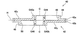
- the center of gravity G42a of the upper half 42a located on the first eccentric cam 44 side of the intermediate disk 42 is located in the second direction (left in FIG. 7) with respect to the rotation axis C of the cam member 40.
- the center of gravity G42b of the lower half 42b located on the second eccentric cam 46 side of the intermediate disc 42 is located in the first direction (right side in FIG. 7) with respect to the rotation axis C of the cam member 40.
- the upper half 42a and the lower half 42a of the intermediate disc 42 have the same dimensions (that is, thickness) in the direction parallel to the rotation axis C of the cam member 40. That is, the upper half 42a and the lower half 42a of the intermediate disc 42 are obtained by bisecting the thickness of the intermediate disc 42 by the plane H perpendicular to the rotation axis C of the cam member 40.
- the plane H shown in FIG. 7 is located at the center of the intermediate disk 42 in the thickness direction, and coincides with the boundary between the upper half 42a and the lower half 42a.
- the center of gravity G42a of the upper half 42a of the intermediate disk 42 and the center of gravity G42b of the lower half 42b of the intermediate disk 42 are positioned at each other in a direction parallel to the rotation axis C of the cam member 40 (that is, in the thickness direction of the cam member 40). Is different. Therefore, the intermediate disc 42 also intentionally has an even-misbalance. As described above, in the cam member 40 of the present embodiment, even and unbalance is intentionally given to the intermediate disc 42, and the first and second eccentric cams 44 and 46 are affected by the even and unbalance of the intermediate disc 42. The resulting even-misbalance is at least partially offset. As a result, the even-misbalance of the cam member 40 as a whole is improved, and unnecessary vibration and noise associated with the rotation of the cam member 40 are reduced.
- the first bottomed hole 48 passes through the upper half 42a of the intermediate disk 42 and reaches the lower half 42b of the intermediate disk 42.
- the depth of the first bottomed hole 48 is not particularly limited as long as it reaches at least the upper half 42a of the intermediate disk 42 and does not penetrate the intermediate disk 42.
- the depth of the second bottomed hole 50 is not particularly limited as long as it reaches at least the lower half 42b of the intermediate disk 42 and does not penetrate the intermediate disk 42.
- the first bottomed hole 48 and the second bottomed hole 50 have the same shape, and the center of gravity G42 of the intermediate disk 42 is the cam member 40. It is located on the rotation axis C of (see FIGS. 5 and 6).
- the first bottomed hole 48 and the second bottomed hole 50 may have different shapes, and in this case, the center of gravity G42 of the intermediate disk 42 is the rotation shaft of the cam member 40. It does not have to be located on C.
- the diameter D44 of the first eccentric cam 44 is equal to the diameter D46 of the second eccentric cam 46.
- the diameter D44 of the first eccentric cam 44 does not necessarily have to be equal to the diameter D46 of the second eccentric cam 46.
- the distance from the rotation axis C of the cam member 40 to the center of gravity G44 of the first eccentric cam 44 is equal to the distance from the rotation axis C of the cam member 40 to the center of gravity G46 of the second eccentric cam 46.
- the distance from the rotation axis C of the cam member 40 to the center of gravity G44 of the first eccentric cam 44 is not necessarily the distance from the rotation axis C of the cam member 40 to the center of gravity G46 of the second eccentric cam 46. It does not have to be equal.
- FIG. 8 shows a cam member 40A as a modified example.
- the first bottomed hole 48 and the second bottomed hole 50 are at least partially filled with a filling member 70 having a density lower than that of the material constituting the intermediate disk 42.
- the even-misbalance of the intermediate disk 42 can be finely adjusted, and the rigidity of the cam member 40 can be increased.
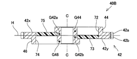
- FIG. 9 shows a cam member 50B of another modified example.
- the intermediate disk 42 is provided with the first through hole 72 and the second through hole 74 in place of the first bottomed hole 48 and the second bottomed hole 50.
- the first through hole 72 is provided with a first balancer 73 located in the lower half 42b of the intermediate disk 42
- the second through hole 74 is provided with a second balancer 73 located in the upper half 42a of the intermediate disk 42.
- a balancer 75 is provided.
- the first balancer 73 and the second balancer 75 are made of a material having a density different from that of the material constituting the intermediate disk 42. In this way, by combining two or more materials having different densities, the cam member 40 can be given an even disproportionate balance without providing the first bottomed hole 48 and the second bottomed hole 50.
- the horticultural trimmer 10 of this embodiment is configured such that each of the first blade 14 and the second blade 16 makes a reciprocating linear motion.
- the technique adopted in this embodiment particularly a part or all of the configuration adopted in the cam member 40, shall also be adopted in a horticultural trimmer configured so that each blade swings back and forth. Can be done.
- the blades 14 and 16 are of a so-called double-edged type, and have cutting edges 14a and 16a on both sides.
- each of the blades 14 and 16 is of a so-called single-edged type, and may have cutting edges 14a and 16a on only one side.
- the horticultural trimmer 10 has a blade that is reciprocally driven at the tip of a long scythe, and is a pole hedge trimmer that cuts hedges in high places, a lawn mower that cuts ridge weeds, or It may be a size mower (scythemower) in which the blade is arranged on the front side of the hand-pushed walking lawn mower and is reciprocated to the left and right in the traveling direction.
Landscapes
- Life Sciences & Earth Sciences (AREA)
- Environmental Sciences (AREA)
- Biodiversity & Conservation Biology (AREA)
- Ecology (AREA)
- Forests & Forestry (AREA)
- Engineering & Computer Science (AREA)
- General Engineering & Computer Science (AREA)
- Mechanical Engineering (AREA)
- Harvester Elements (AREA)
Abstract
カム部材は、中間ディスクと、中間ディスクの上面に設けられているとともに第1ブレードに接続された第1偏心カムと、中間ディスクの下面に設けられているとともに第2ブレードに接続された第2偏心カムとを備える。第1偏心カムの重心はカム部材の回転軸に対して第1方向に位置しており、第2偏心カムの重心はカム部材の回転軸に対して第1方向とは反対向きの第2方向に位置している。中間ディスクの第1偏心カム側に位置する上半分の重心は、カム部材の回転軸に対して第2方向に位置しており、中間ディスクの第2偏心カム側に位置する下半分の重心は、カム部材の回転軸に対して第1方向に位置している。
Description
本開示は、例えばヘッジトリマや芝刈機といった園芸用トリマに関する。
例えばヘッジトリマや芝刈機といった、様々な種類の園芸用トリマが知られている。一般に、園芸用トリマは、原動機(例えば、エンジンやモータ)と、原動機によって回転駆動されるカム部材と、カム部材に接続された一対のブレードとを備える。一対のブレードは、カム部材の回転運動に応じて、互いに逆位相で往復運動する。例えば実開平6-17434号公報に、園芸用トリマの一例が記載されている。
カム部材は、第1ブレードに接続された第1偏心カムと、第2ブレードに接続された第2偏心カムとを有する。第1偏心カムと第2偏心カムは、カム部材の回転軸に沿って配置されているとともに、カム部材の回転軸に対して、互いに反対方向へオフセットされている。このような構成によって、カム部材には、偶不釣り合い(couple unbalance)が不可避的に存在しており、その結果、カム部材の回転に伴って無用な振動や騒音が発生してしまう。
上記した実情を鑑みて、本明細書は、カム部材の偶不釣り合いを低減し得る技術を提供する。
本明細書が開示する技術の一側面により、園芸用トリマが提供される。この園芸用トリマは、原動機と、原動機によって回転駆動されるカム部材と、カム部材に接続されており、カム部材の回転運動に応じて互いに逆位相で往復運動する第1ブレード及び第2ブレードとを備える。カム部材は、中間ディスクと、中間ディスクの上面に設けられているとともに第1ブレードに接続された第1偏心カムと、中間ディスクの下面に設けられているとともに第2ブレードに接続された第2偏心カムとを備える。第1偏心カムの重心は、カム部材の回転軸に対して第1方向に位置しており、第2偏心カムの重心は、カム部材の回転軸に対して第1方向とは反対向きの第2方向に位置している。中間ディスクの第1偏心カム側に位置する上半分の重心は、カム部材の回転軸に対して第2方向に位置しており、中間ディスクの第2偏心カム側に位置する下半分の重心は、カム部材の回転軸に対して第1方向に位置している。ここで、中間ディスクの上半分及び下半分は、回転軸に平行な方向における寸法(即ち、厚み)が、互いに等しいものとする。
上記した構成では、カム部材の中間ディスクに、偶不釣り合いが意図的に与えられており、その中間ディスクの偶不釣り合いによって、第1及び第2偏心カムに起因する偶不釣り合いが、少なくとも部分的に相殺される。これにより、カム部材の全体としての偶不釣り合いが改善されることで、カム部材の回転に伴う無用な振動や騒音が低減される。
本技術の一実施形態において、カム部材の中間ディスクは、中間ディスクの厚み方向(即ち、カム部材の回転軸に平行な方向)に形成された少なくとも一つの有底穴を有してもよい。中間ディスクにそのような有底穴を設けることで、中間ディスクに所望の偶不釣り合いを与えることができる。ここで、有底穴は、第1偏心カム又は第2偏心カムの位置に設けられてもよいし、第1偏心カム又は第2偏心カムから離れた位置に設けられてもよい。
上記した実施形態において、少なくとも一つの有底穴は、第1偏心カムを通過して中間ディスクへ延びる第1有底穴を含んでもよい。このような構成によると、第1偏心カムの質量が削減されることによって、第1偏心カムに起因する偶不釣り合いを低減することができる。
上記に加え、又は代えて、少なくとも一つの有底穴は、第2偏心カムを通過して中間ディスクへ延びる第2有底穴を含んでもよい。このような構成によると、第2偏心カムの質量が削減されることによって、第2偏心カムに起因する偶不釣り合いを低減することができる。
本技術の一実施形態において、少なくとも一つの有底穴は、中間ディスクを構成する材料よりも密度の小さい充填部材によって、少なくとも部分的に満たされていてもよい。このような構成によると、例えば、中間ディスクの偶不釣り合いを細かく調整したり、カム部材の剛性を高めたりすることができる。
本技術の一実施形態において、カム部材の中間ディスクは、密度の異なる少なくとも二つの材料によって構成されていてもよい。このような構成によっても、上述した有底穴の有無にかかわらず、カム部材の中間ディスクに、所望の偶不釣り合いを与えることができる。
本技術の一実施形態において、カム部材の中間ディスクの重心は、カム部材の回転軸上に位置していてもよい。但し、他の実施形態として、カム部材の中間ディスクの重心は、必ずしもカム部材の回転軸上に位置していなくてもよい。
本技術の一実施形態において、第1偏心カムの直径は、第2偏心カムの直径と等しくてもよい。但し、他の実施形態として、第1偏心カムの直径は、必ずしも第2偏心カムの直径と等しくなくてもよい。
本技術の一実施形態において、カム部材の回転軸から第1偏心カムの重心までの距離は、カム部材の回転軸から第2偏心カムの重心までの距離に等しくてもよい。但し、他の実施形態として、カム部材の回転軸から第1偏心カムの重心までの距離は、必ずしもカム部材の回転軸から第2偏心カムの重心までの距離と等しくなくてもよい。
本技術の一実施形態において、第1偏心カムと第2偏心カムとの少なくとも一方は、少なくとも一つのリンクを介して、対応する第1ブレード又は第2ブレードに接続されていてもよい。あるいは、他の実施形態として、第1偏心カムと第2偏心カムとの少なくとも一方は、対応する第1ブレード又は第2ブレードと、直接的に接続されていてもよい。
本技術の一実施形態において、第1偏心カムは、その全体が中間ディスクの上面に位置していてもよい。加えて、第2偏心カムは、その全体が中間ディスクの下面に位置していてもよい。但し、他の実施形態として、第1偏心カムと第2偏心カムの少なくとも一方が、中間ディスクに対して周方向の外側へ突出していてもよい。
以下では、本開示の代表的かつ非限定的な具体例について、図面を参照して詳細に説明する。この詳細な説明は、本開示の好ましい例を実施するための詳細を当業者に示すことを単純に意図しており、本開示の範囲を限定することを意図したものではない。また、以下に開示される追加的な特徴ならびに技術は、さらに改善された園芸用トリマを提供するために、他の特徴や技術とは別に、又は共に用いることができる。
また、以下の詳細な説明で開示される特徴や工程の組み合わせは、最も広い意味において本開示を実施する際に必須のものではなく、特に本開示の代表的な具体例を説明するためにのみ記載されるものである。さらに、上記及び下記の代表的な具体例の様々な特徴、ならびに、独立及び従属クレームに記載されるものの様々な特徴は、本開示の追加的かつ有用な実施形態を提供するにあたって、ここに記載される具体例のとおりに、あるいは列挙された順番のとおりに組合せなければならないものではない。
本明細書及び/又は請求の範囲に記載された全ての特徴は、実施例及び/又はクレームに記載された特徴の構成とは別に、出願当初の開示ならびにクレームされた特定事項に対する限定として、個別に、かつ互いに独立して開示されることを意図するものである。さらに、全ての数値範囲及びグループ又は集団に関する記載は、出願当初の開示ならびにクレームされた特定事項に対する限定として、それらの中間の構成を開示する意図を持ってなされている。
図面を参照して、実施例の園芸用トリマ10を説明する。園芸用トリマ10は、主に生垣や植木の剪定に用いられる園芸工具であり、ヘッジトリマとも称される。図1に示すように、園芸用トリマ10は、本体12と、本体12から前方に延びる一対のブレード14、16とを備える。一対のブレード14、16は、本体12に固定されたガイドバー18によって支持されている。ガイドバー18は、一対のブレード14、16に沿って、本体12から前方に延びている。園芸用トリマ10は、一対のブレード14、16を互いに逆位相で往復運動させることによって、生垣や植木の枝葉を切断する。
一対のブレード14、16には、第1ブレード14と第2ブレード16とが含まれる。第1ブレード14には、前後方向に沿って、複数の刃先14aが設けられている。各々の刃先14aは、第1ブレード14から左方又は右方に突出している。同様に、第2ブレード16にも、前後方向に沿って複数の刃先16aが設けられている。各々の刃先16aは、第2ブレード16から左方又は右方に突出している。第1ブレード14と第2ブレード16とが逆位相で往復運動すると、第1ブレード14の刃先14aと第2ブレード16の刃先16aとが繰り返し交差する。これにより、例えば生垣の枝葉が切断される。
本体12は、バッテリパック2が着脱可能に構成されている。即ち、本実施例の園芸用トリマ10は、バッテリパック2を電源とするコードレスタイプの電動工具である。ここで、バッテリパック2の数は一つに限定されず、園芸用トリマ10は、二以上のバッテリパック2を使用するように構成されてもよい。なお、他の実施形態として、園芸用トリマ10は、外部の交流電源又は直流電源に、コードを介して接続される電動工具であってもよい。あるいは、園芸用トリマ10は、エンジン駆動型の工具であってもよい。
図1、図2に示すように、本体12は、ハウジング20と、ハウジング20に固定されたカムケース38と、ハウジング20内でカムケース38に固定されたモータ22とを備える。モータ22は、一対のブレード14、16を駆動するための原動機であり、バッテリパック2から供給される電力によって動作する。ハウジング20には、前方グリップ30と後方グリップ32とが設けられている。これらのグリップ30、32は、ユーザによって把持されるように構成されている。通常、ユーザは、左手で前方グリップ30を把持し、右手で後方グリップ32を把持することで、園芸用トリマ10を操作する。
後方グリップ32には、駆動スイッチ34と、アンロックスイッチ36が設けられている。ユーザが駆動スイッチ34を操作すると、バッテリパック2からモータ22に電力が供給され、モータ22が一対のブレード14、16を駆動する。但し、駆動スイッチ34は、通常、ハウジング20の内部で機械的にロックされており、アンロックスイッチ36が操作されている間に限って、駆動スイッチ34の機械的なロックが解除される。これにより、駆動スイッチ34の誤操作によって、一対のブレード14、16が意図せず駆動されることが防止される。
図3、図4に示すように、園芸用トリマ10は、カム部材40を備える。カム部材40は、特に限定されないが、金属で構成されている。カム部材40は、カムケース38内に位置しており、カムケース38によって回転可能に保持されている。カム部材40は、モータ22に接続されており、モータ22によって回転駆動される。カム部材40は、中間ディスク42と、第1偏心カム44と、第2偏心カム46とを備える。第1偏心カム44及び第2偏心カム46は、中間ディスク42に対して固定されており、中間ディスク42と共に一体となって回転する。一例ではあるが、本実施例におけるカム部材40では、第1偏心カム44及び第2偏心カム46が、中間ディスク42と一体に形成されている。
第1偏心カム44は、中間ディスク42の上面42xに設けられており、カム部材40の回転軸Cに対して、第1方向(図4において右方)にオフセットされている。第1偏心カム44は、第1リンク60を介して第1ブレード14に接続されている。なお、第1偏心カム44は、第1リンク60を介することなく、第1ブレード14と直接的に接続されてもよい。第2偏心カム46は、中間ディスク42の下面42yに設けられており、カム部材40の回転軸Cに対して、第1方向とは反対の第2方向(図4において左方)にオフセットされている。第2偏心カム46は、第2リンク62を介して第2ブレード16に接続されている。第2偏心カム46についても、第2リンク62を介することなく、第2ブレード16と直接的に接続されてもよい。
以上の構成により、モータ22によってカム部材40が回転すると、第1偏心カム44及び第2偏心カム46は、カム部材40の回転軸Cを中心としてそれぞれ公転する。第1偏心カム44が公転することで、第1偏心カム44に接続された第1ブレード14は、前後方向に沿って往復運動する。同様に、第2偏心カム46が公転することで、第2偏心カム46に接続された第2ブレード16は、前後方向に沿って往復運動する。このとき、第1偏心カム44及び第2偏心カム46が、互いに逆位相で公転するので、第1ブレード14及び第2ブレード16も、互いに逆位相で往復運動する。
次に、図5、図6、図7を参照して、カム部材40の詳細な構成について説明する。カム部材40の中間ディスク42は、ディスク形状を有しており、その中心軸は、カム部材40の回転軸Cに一致する。中間ディスク42のサイズは十分に大きく、第1偏心カム44の全体が中間ディスク42の上面42xに位置しており、第2偏心カム46の全体が中間ディスク42の下面42yに位置している。中間ディスク42の外周面42eには、モータ22と係合するためのヘリカルギアが設けられている。また、中間ディスク42には、カム部材40を軽量化するために、複数の貫通孔43が形成されている。中間ディスク42の重心G42は、カム部材40の回転軸C上に位置している。
前述したように、第1偏心カム44は、カム部材40の回転軸Cに対して、第1方向(図5において右方)にオフセットされている。従って、第1偏心カム44の重心G44も、カム部材40の回転軸Cに対して第1方向に位置している(図5参照)。一方、第2偏心カム46は、カム部材40の回転軸Cに対して、第2方向(図6において左方)にオフセットされている。従って、第2偏心カム46の重心G46も、カム部材40の回転軸Cに対して第2方向に位置している(図6参照)。ここで、図7に示すように、第1偏心カム44の重心G44と、第2偏心カム46の重心G46は、カム部材40の回転軸Cに平行な方向に関して(即ち、カム部材40の厚み方向に関して)、互い位置が異なる。そのことから、カム部材40には、第1偏心カム44及び第2偏心カム46に起因する偶不釣り合い(couple unbalance)が存在しており、このような偶不釣り合いは、カム部材40の回転に伴って無用な振動や騒音を発生させる要因となる。
上記の問題に関して、本実施例におけるカム部材40は、第1有底穴48と第2有底穴50とを備える。第1有底穴48は、第1偏心カム44に設けられている。第1有底穴48は、第1偏心カム44を通過して、中間ディスク42に達する深さを有している。但し、第1有底穴48は、中間ディスク42を貫通していない。一方、第2有底穴50は、第2偏心カム46に設けられている。第2有底穴50は、第2偏心カム46を通過して、中間ディスク42に達する深さを有している。第2有底穴50についても、中間ディスク42を貫通していない。このような構成によると、中間ディスク42の第1偏心カム44側に位置する上半分42aの重心G42aは、カム部材40の回転軸Cに対して第2方向(図7における左方)に位置する。また、中間ディスク42の第2偏心カム46側に位置する下半分42bの重心G42bは、カム部材40の回転軸Cに対して第1方向(図7における右方)に位置する。
ここで、中間ディスク42の上半分42aと下半分42aは、カム部材40の回転軸Cに平行な方向における寸法(即ち、厚み)が、互いに等しい。即ち、中間ディスク42の上半分42aと下半分42aは、カム部材40の回転軸Cに垂直な平面Hによって、中間ディスク42の厚みを二等分したものである。なお、図7中に示す平面Hは、中間ディスク42の厚み方向における中央に位置しており、上半分42aと下半分42aとの境界に一致している。
中間ディスク42の上半分42aの重心G42aと、中間ディスク42の下半分42bの重心G42bは、カム部材40の回転軸Cに平行な方向に関して(即ち、カム部材40の厚み方向に関して)、互い位置が異なる。従って、中間ディスク42にも、意図的に偶不釣り合いが存在している。このように、本実施例のカム部材40では、中間ディスク42にも偶不釣り合いが意図的に与えられており、中間ディスク42の偶不釣り合いによって、第1及び第2偏心カム44、46に起因する偶不釣り合いが、少なくとも部分的に相殺される。これにより、カム部材40の全体としての偶不釣り合いが改善されることで、カム部材40の回転に伴う無用な振動や騒音が低減される。
本実施例では、第1有底穴48が、中間ディスク42の上半分42aを通過して、中間ディスク42の下半分42bに達している。しかしながら、第1有底穴48は、少なくとも中間ディスク42の上半分42aに達していればよく、中間ディスク42を貫通しない限りにおいて、その深さは特に限定されない。同様に、第2有底穴50についても、少なくとも中間ディスク42の下半分42bに達していればよく、中間ディスク42を貫通しない限りにおいて、その深さは特に限定されない。
本実施例では、図5、図6に示すように、第1有底穴48と第2有底穴50とが同一の形状を有しており、中間ディスク42の重心G42が、カム部材40の回転軸C上に位置している(図5、図6参照)。しかしながら、他の実施形態として、第1有底穴48と第2有底穴50とが互いに異なる形状を有してもよく、この場合、中間ディスク42の重心G42が、カム部材40の回転軸C上に位置しなくてもよい。
本実施例では、図5、図6に示すように、第1偏心カム44の直径D44が、第2偏心カム46の直径D46と等しい。しかしながら、他の実施形態として、第1偏心カム44の直径D44は、必ずしも第2偏心カム46の直径D46と等しくなくてもよい。また、本実施例では、カム部材40の回転軸Cから第1偏心カム44の重心G44までの距離は、カム部材40の回転軸Cから第2偏心カム46の重心G46までの距離に等しい。しかしながら、他の実施形態として、カム部材40の回転軸Cから第1偏心カム44の重心G44までの距離は、必ずしもカム部材40の回転軸Cから第2偏心カム46の重心G46までの距離と等しくなくてもよい。
図8は、一変形例のカム部材40Aを示す。このカム部材40Aでは、第1有底穴48及び第2有底穴50が、中間ディスク42を構成する材料よりも密度の小さい充填部材70によって、少なくとも部分的に満たされている。このような構成によると、例えば、中間ディスク42の偶不釣り合いを細かく調整したり、カム部材40の剛性を高めたりすることができる。
図9は、他の一変形例のカム部材50Bを示す。このカム部材40Bでは、第1有底穴48及び第2有底穴50に代えて、中間ディスク42に第1貫通孔72及び第2貫通孔74が設けられている。そして、第1貫通孔72には、中間ディスク42の下半分42bに位置する第1バランサ73が設けられており、第2貫通孔74には、中間ディスク42の上半分42aに位置する第2バランサ75が設けられている。第1バランサ73と第2バランサ75は、中間ディスク42を構成する材料とは密度の異なる材料によって構成されている。このように、密度の異なる二以上の材料を組み合わせることによって、第1有底穴48及び第2有底穴50を設けることなく、カム部材40に偶不釣り合いを与えることができる。
本実施例の園芸用トリマ10は、第1ブレード14と第2ブレード16との各々が、往復直線運動するように構成されている。しかしながら、本実施例に採用された技術、特に、カム部材40に採用された構成の一部又は全部は、各々のブレードが往復揺動運動するように構成された園芸用トリマにも採用することができる。
本実施形態の園芸用トリマ10では、各々のブレード14、16が、いわゆる両刃タイプのものであって、両側に刃先14a、16aを有している。しかしながら、各々のブレード14、16は、いわゆる片刃タイプのものであって、一方側のみに刃先14a、16aを有してもよい。また、他の実施形態として、園芸用トリマ10は、長い棹の先端に往復駆動されるブレードを有し、高所の生垣を切断するポールヘッジトリマ、畦の雑草を切断する畦刈機、あるいは、ブレードが手押しの歩行型芝刈機の前側に配置され、進行方向左右に往復駆動されるサイズモア(scythe mower)であってもよい。
Claims (10)
- 園芸用トリマであって、
原動機と、
前記原動機によって回転駆動されるカム部材と、
前記カム部材に接続されており、前記カム部材の回転運動に応じて互いに逆位相で往復運動する第1ブレード及び第2ブレードと、
を備え、
前記カム部材は、中間ディスクと、前記中間ディスクの上面に設けられているとともに前記第1ブレードに接続された第1偏心カムと、前記中間ディスクの下面に設けられているとともに前記第2ブレードに接続された第2偏心カムと、を備え、
前記第1偏心カムの重心は、前記カム部材の回転軸に対して、第1方向に位置しており、
前記第2偏心カムの重心は、前記カム部材の回転軸に対して、前記第1方向とは反対向きの第2方向に位置しており、
前記中間ディスクの前記第1偏心カム側に位置する上半分の重心は、前記カム部材の回転軸に対して、前記第2方向に位置しており、
前記中間ディスクの前記第2偏心カム側に位置する下半分の重心は、前記カム部材の回転軸に対して、前記第1方向に位置している、
園芸用トリマ。 - 前記カム部材の前記中間ディスクは、前記中間ディスクの厚み方向に形成された、少なくとも一つの有底穴を有する、請求項1に記載の園芸用トリマ。
- 前記少なくとも一つの有底穴は、前記第1偏心カムを通過して前記中間ディスクへ延びる第1有底穴を含む、請求項2に記載の園芸用トリマ。
- 前記少なくとも一つの有底穴は、前記第2偏心カムを通過して前記中間ディスクへ延びる第2有底穴を含む、請求項2又は3に記載の園芸用トリマ。
- 前記少なくとも一つの有底穴は、前記中間ディスクを構成する材料よりも密度の小さい充填部材によって、少なくとも部分的に満たされている、請求項2から4のいずれか一項に記載の園芸用トリマ。
- 前記カム部材の前記中間ディスクは、密度の異なる少なくとも二つの材料によって構成されている、請求項1から5のいずれか一項に記載の園芸用トリマ。
- 前記カム部材の前記中間ディスクの重心は、前記カム部材の前記回転軸上に位置している、請求項1から6のいずれか一項に記載の園芸用トリマ。
- 前記第1偏心カムの直径は、前記第2偏心カムの直径と等しい、請求項1から7のいずれか一項に記載の園芸用トリマ。
- 前記カム部材の前記回転軸から前記第1偏心カムの前記重心までの距離は、前記カム部材の前記回転軸から前記第2偏心カムの前記重心までの距離に等しい、請求項1から8のいずれか一項に記載の園芸用トリマ。
- 前記第1偏心カムと前記第2偏心カムとの少なくとも一方は、少なくとも一つのリンクを介して、対応する前記第1ブレード又は前記第2ブレードに接続されている、請求項1から9のいずれか一項に記載の園芸用トリマ。
Priority Applications (3)
| Application Number | Priority Date | Filing Date | Title |
|---|---|---|---|
| DE112020003775.4T DE112020003775T5 (de) | 2019-08-08 | 2020-07-07 | Gartenschere |
| CN202080054314.3A CN114173547B (zh) | 2019-08-08 | 2020-07-07 | 园艺用修剪机 |
| US17/633,276 US12382877B2 (en) | 2019-08-08 | 2020-07-07 | Gardening trimmer |
Applications Claiming Priority (2)
| Application Number | Priority Date | Filing Date | Title |
|---|---|---|---|
| JP2019-146335 | 2019-08-08 | ||
| JP2019146335A JP7296819B2 (ja) | 2019-08-08 | 2019-08-08 | 園芸用トリマ |
Publications (1)
| Publication Number | Publication Date |
|---|---|
| WO2021024684A1 true WO2021024684A1 (ja) | 2021-02-11 |
Family
ID=74502924
Family Applications (1)
| Application Number | Title | Priority Date | Filing Date |
|---|---|---|---|
| PCT/JP2020/026613 Ceased WO2021024684A1 (ja) | 2019-08-08 | 2020-07-07 | 園芸用トリマ |
Country Status (5)
| Country | Link |
|---|---|
| US (1) | US12382877B2 (ja) |
| JP (1) | JP7296819B2 (ja) |
| CN (1) | CN114173547B (ja) |
| DE (1) | DE112020003775T5 (ja) |
| WO (1) | WO2021024684A1 (ja) |
Families Citing this family (6)
| Publication number | Priority date | Publication date | Assignee | Title |
|---|---|---|---|---|
| JP2022053268A (ja) * | 2020-09-24 | 2022-04-05 | 株式会社やまびこ | ヘッジトリマー |
| USD1037802S1 (en) * | 2021-06-09 | 2024-08-06 | Jiangsu Dongcheng Tools Technology Co., Ltd. | Pruning machine |
| USD1034127S1 (en) * | 2021-06-09 | 2024-07-09 | Jiangsu Dongcheng Tools Technology Co., Ltd. | Electric chain saw |
| DE102023202455A1 (de) * | 2023-03-20 | 2024-09-26 | Robert Bosch Gesellschaft mit beschränkter Haftung | Messeranordnung für ein Gartengerät |
| US20240397878A1 (en) * | 2023-06-04 | 2024-12-05 | Greenworks (Jiangsu) Co., Ltd. | Hedge Trimmer |
| CN117243008B (zh) * | 2023-11-03 | 2025-02-25 | 淮安中绿园林机械制造有限公司 | 一种可快换刀条的绿篱机 |
Citations (3)
| Publication number | Priority date | Publication date | Assignee | Title |
|---|---|---|---|---|
| JPH0617434U (ja) * | 1992-08-14 | 1994-03-08 | 株式会社共立 | バリカン形刈払機 |
| JP2000217431A (ja) * | 1999-01-28 | 2000-08-08 | Delta Kogyo Co Ltd | カム構造およびこのカム構造を用いたカム装置並びにこのカム装置を用いた刈込み機 |
| JP2010158205A (ja) * | 2009-01-08 | 2010-07-22 | Makita Corp | 園芸用バリカンとそのブレードアセンブリ |
Family Cites Families (28)
| Publication number | Priority date | Publication date | Assignee | Title |
|---|---|---|---|---|
| US2790295A (en) * | 1954-09-28 | 1957-04-30 | Int Harvester Co | Reciprocating sickle assembly with counterbalanced drive means |
| JPH0617434A (ja) | 1992-06-30 | 1994-01-25 | Hajime Matsuoka | 基礎構造及びその施工法 |
| US6735876B2 (en) * | 2001-03-01 | 2004-05-18 | Makita Corporation | Blade clamps suitable for reciprocating power tools |
| JP4110962B2 (ja) | 2002-12-24 | 2008-07-02 | 株式会社デンソー | 回転体のバランス修正方法 |
| JP4958529B2 (ja) * | 2006-12-08 | 2012-06-20 | 株式会社やまびこ | 刈込機 |
| US20080196376A1 (en) * | 2007-02-15 | 2008-08-21 | Husqvarna Outdoor Products Inc. | Separator plate for power tool |
| JP5021568B2 (ja) * | 2008-05-20 | 2012-09-12 | 株式会社源平刃物工場 | バリカン式刈刃装置 |
| DE102008062603A1 (de) * | 2008-12-17 | 2010-10-21 | Andreas Stihl Ag & Co. Kg | Arbeitsgerät |
| DE102009012175A1 (de) * | 2009-02-27 | 2010-09-02 | Andreas Stihl Ag & Co. Kg | Elektroarbeitsgerät mit einem Akkupack |
| JP5208878B2 (ja) * | 2009-08-05 | 2013-06-12 | 株式会社マキタ | 園芸用バリカン |
| DE102009040589A1 (de) * | 2009-09-08 | 2011-03-10 | Gardena Manufacturing Gmbh | Motorisch angetriebenes handgeführtes Schneidgerät, Verfahren zu dessen Herstellung und Doppelmesseranordnung |
| DE102010005964A1 (de) * | 2010-01-28 | 2011-08-18 | Andreas Stihl AG & Co. KG, 71336 | Exzentergetriebeanordnung |
| CN102308723B (zh) | 2010-07-06 | 2013-08-21 | 南京德朔实业有限公司 | 用于修剪及切割植被的手持动力工具 |
| DE102010033978A1 (de) * | 2010-08-11 | 2012-02-16 | Andreas Stihl Ag & Co. Kg | Handgeführtes Arbeitsgerät |
| EP2814313A4 (en) * | 2012-02-17 | 2015-09-30 | Husqvarna Ab | CUTTING DEVICE DRIVEN BY AN ENGINE HAND-HELD |
| JP5995558B2 (ja) * | 2012-07-04 | 2016-09-21 | 株式会社マキタ | 園芸用バリカン |
| US9603311B2 (en) * | 2013-11-29 | 2017-03-28 | Techtronic Outdoor Products Technology Limited | Reciprocating power tool |
| EP2965616B1 (en) * | 2014-07-11 | 2020-04-22 | Black & Decker Inc. | Vegetation cutting device |
| US20160227710A1 (en) * | 2015-02-09 | 2016-08-11 | Jenn Feng New Energy Co., Ltd. | Power-driven hedge trimmer with movable power assembly |
| US10098285B2 (en) * | 2015-02-25 | 2018-10-16 | Chervon (Hk) Limited | Gardening tool and hedge trimmer |
| US20160330914A1 (en) * | 2015-05-14 | 2016-11-17 | Jenn Feng New Energy Co., Ltd. | Hedge trimmer |
| DE102015216251A1 (de) * | 2015-08-26 | 2017-03-02 | Robert Bosch Gmbh | Oszillationsgartengerät, Getriebeelement eines Oszillationsgartengeräts und Verfahren mit einem Oszillationsgartengerät |
| CA3005663A1 (en) * | 2015-11-18 | 2017-05-26 | Tti (Macao Commercial Offshore) Limited | Hedge trimmer |
| US10375896B2 (en) * | 2016-04-21 | 2019-08-13 | Black & Decker, Inc. | Pole hedge trimmer |
| US10136584B1 (en) * | 2017-04-26 | 2018-11-27 | George Larry Cours | Dual reciprocating blade landscape saw with enhanced durability and performance |
| CN109452026A (zh) * | 2017-09-06 | 2019-03-12 | 南京德朔实业有限公司 | 修枝机 |
| US10827673B2 (en) * | 2017-12-22 | 2020-11-10 | Cnh Industrial America Llc | Center knife drive for an agricultural harvester |
| DE102020005909A1 (de) * | 2019-10-07 | 2021-04-08 | Makita Corporation | Heckenschere |
-
2019
- 2019-08-08 JP JP2019146335A patent/JP7296819B2/ja active Active
-
2020
- 2020-07-07 CN CN202080054314.3A patent/CN114173547B/zh active Active
- 2020-07-07 DE DE112020003775.4T patent/DE112020003775T5/de active Pending
- 2020-07-07 WO PCT/JP2020/026613 patent/WO2021024684A1/ja not_active Ceased
- 2020-07-07 US US17/633,276 patent/US12382877B2/en active Active
Patent Citations (3)
| Publication number | Priority date | Publication date | Assignee | Title |
|---|---|---|---|---|
| JPH0617434U (ja) * | 1992-08-14 | 1994-03-08 | 株式会社共立 | バリカン形刈払機 |
| JP2000217431A (ja) * | 1999-01-28 | 2000-08-08 | Delta Kogyo Co Ltd | カム構造およびこのカム構造を用いたカム装置並びにこのカム装置を用いた刈込み機 |
| JP2010158205A (ja) * | 2009-01-08 | 2010-07-22 | Makita Corp | 園芸用バリカンとそのブレードアセンブリ |
Also Published As
| Publication number | Publication date |
|---|---|
| DE112020003775T5 (de) | 2022-07-07 |
| CN114173547B (zh) | 2023-07-04 |
| JP7296819B2 (ja) | 2023-06-23 |
| CN114173547A (zh) | 2022-03-11 |
| US20220354061A1 (en) | 2022-11-10 |
| US12382877B2 (en) | 2025-08-12 |
| JP2021023260A (ja) | 2021-02-22 |
Similar Documents
| Publication | Publication Date | Title |
|---|---|---|
| JP7296819B2 (ja) | 園芸用トリマ | |
| JP7261734B2 (ja) | 園芸用トリマ | |
| JP7175843B2 (ja) | 園芸用トリマ | |
| JP5995558B2 (ja) | 園芸用バリカン | |
| JP2021180645A (ja) | 園芸用トリマ | |
| JP7610453B2 (ja) | 園芸用トリマ | |
| CN222193147U (zh) | 手扶式割草机 | |
| JP2018102235A (ja) | カッタブレード及び芝刈機 | |
| JP2018102234A (ja) | カッタブレード及び芝刈機 | |
| JPH02308711A (ja) | 草刈機 | |
| JP2021029114A (ja) | 刈払機用の回転刈刃 | |
| JP7695165B2 (ja) | 作業機およびブレードユニット | |
| JP2008237087A (ja) | 園芸バリカンとそれに用いるブレードアセンブリ | |
| JP2006314277A (ja) | 刈払機 | |
| JP4657094B2 (ja) | 刈込機 | |
| JP4469224B2 (ja) | ヘッジトリマー | |
| JP5035827B2 (ja) | 草刈機 | |
| JP3736256B2 (ja) | ヘッジトリマー | |
| JP6257954B2 (ja) | 芝生バリカン | |
| JP2017143772A (ja) | 草刈り機用回転刃 | |
| JP2020156424A (ja) | 作業機 | |
| JP2003250340A (ja) | 刈込み装置 | |
| US1340800A (en) | Cutter | |
| KR101440689B1 (ko) | 예초기 | |
| JP2021093926A (ja) | ハンマーナイフ式草刈機 |
Legal Events
| Date | Code | Title | Description |
|---|---|---|---|
| 121 | Ep: the epo has been informed by wipo that ep was designated in this application |
Ref document number: 20849538 Country of ref document: EP Kind code of ref document: A1 |
|
| 122 | Ep: pct application non-entry in european phase |
Ref document number: 20849538 Country of ref document: EP Kind code of ref document: A1 |
|
| WWG | Wipo information: grant in national office |
Ref document number: 17633276 Country of ref document: US |