WO2021024473A1 - 到来方向推定装置及び方法 - Google Patents
到来方向推定装置及び方法 Download PDFInfo
- Publication number
- WO2021024473A1 WO2021024473A1 PCT/JP2019/031448 JP2019031448W WO2021024473A1 WO 2021024473 A1 WO2021024473 A1 WO 2021024473A1 JP 2019031448 W JP2019031448 W JP 2019031448W WO 2021024473 A1 WO2021024473 A1 WO 2021024473A1
- Authority
- WO
- WIPO (PCT)
- Prior art keywords
- arrival
- estimating
- arrival direction
- radio signal
- direction estimation
- Prior art date
- Legal status (The legal status is an assumption and is not a legal conclusion. Google has not performed a legal analysis and makes no representation as to the accuracy of the status listed.)
- Ceased
Links
Images
Classifications
-
- G—PHYSICS
- G01—MEASURING; TESTING
- G01S—RADIO DIRECTION-FINDING; RADIO NAVIGATION; DETERMINING DISTANCE OR VELOCITY BY USE OF RADIO WAVES; LOCATING OR PRESENCE-DETECTING BY USE OF THE REFLECTION OR RERADIATION OF RADIO WAVES; ANALOGOUS ARRANGEMENTS USING OTHER WAVES
- G01S7/00—Details of systems according to groups G01S13/00, G01S15/00, G01S17/00
- G01S7/02—Details of systems according to groups G01S13/00, G01S15/00, G01S17/00 of systems according to group G01S13/00
Definitions
- the present invention relates to an arrival direction estimation device and a method for estimating the arrival direction of radio waves, for example, for a radar device or the like.
- MUSIC method Multiple Signal Classification
- the arrival direction (DOA) is estimated by estimating the frequency component of the autocorrelation matrix of the received signal by the eigenspace method.
- a signal x of dimension M including p complex sine waves is assumed in the presence of white noise of Gaussian distribution, and an autocorrelation matrix Rx is considered for this.
- the eigenvalues of the autocorrelation matrix Rx are sorted in descending order, the subspace spanned by the eigenvectors corresponding to the first p eigenvalues (that is, the eigenvectors corresponding to the direction of large variance) is called a signal subspace.
- the remaining MP eigenvectors span a subspace orthogonal to the signal subspace, and contain only noise inside.
- the MUSIC method is a method of estimating the arrival direction of p complex sine waves by utilizing the orthogonality between the signal subspace and the noise subspace in this way.
- This method can estimate the direction of arrival of the target with extremely high resolution, but it has been a problem because a false image (spurious) may occur at a position where there is originally no target. Another problem is that the processing time is long and the number of targets that can be detected at the same time when used in real time is limited.
- An object of the present invention is to provide an arrival direction estimation device and a method capable of solving the above problems, preventing the occurrence of false images, and increasing the number of targets.
- the arrival direction estimation device is An arrival direction estimation device including a control unit that scans the reception direction, receives a radio signal, and estimates the arrival direction of the radio signal.
- the control unit Using the first arrival direction estimation method, the arrival direction of the received radio signal is estimated, and the arrival direction is estimated.
- the radio signal having an arrival direction having a received power value equal to or less than a predetermined threshold value is excluded, or the maximum peak value of the received power values of the estimated radio signal is excluded.
- a second arrival direction estimation method having a resolution higher than that of the first arrival direction estimation method is used to exclude radio signals having an arrival direction other than the range of the main beam having the above. Estimate the direction of arrival.
- the method for estimating the direction of arrival according to the second invention is It is an arrival direction estimation method for an arrival direction estimation device provided with a control unit that scans a reception direction, receives a radio signal, and estimates the arrival direction of the radio signal.
- a step in which the control unit estimates the arrival direction of the received radio signal by using the first arrival direction estimation method The control unit excludes a radio signal having an arrival direction having a received power value equal to or less than a predetermined threshold value from the received power values of the estimated radio signal, or the received power value of the estimated radio signal.
- radio signals having an arrival direction other than the range of the main beam having the maximum peak value are excluded, and a second arrival direction estimation method having a resolution higher than that of the first arrival direction estimation method is used. It includes a step of estimating the arrival direction of the received radio signal.
- the arrival direction estimation device and method according to the present invention it is possible to prevent the occurrence of false images and increase the number of targets.
- an arrival direction estimation technique called a beamformer method is used.
- the Beamformer method has a lower resolution than the MUSIC method, but is characterized in that false images are less likely to occur and the processing time is short.
- the Beamformer method is the most basic and traditional method of estimating the direction of arrival, and scans the main lobe (main beam) of a uniform array antenna in all directions to increase the output power of the array (DOA). ) Is a way to find it.
- each weight may be set to a predetermined value from the common mode condition (the condition of aligning the phases so as to be in phase). Then, the angle ⁇ is changed from ⁇ 90 degrees to +90 degrees, and the peak of the output power of the array antenna is searched for.
- angular spectrum P BF (theta) using the correlation matrix of the received signal Rxx and the mode vector a (theta), from the position of the peak of the angular spectrum P BF (theta) when changing the angle theta
- the direction of arrival can be known, and the input power of the incoming wave can be known from the height of the peak.
- the present embodiment is characterized in that the arrival direction is estimated by the following procedure.
- the arrival direction is estimated by the Beamformer method.
- an angle having a received power equal to or higher than a preset threshold value is extracted.
- the arrival direction is estimated by the MUSIC method.
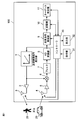
- FIG. 1 is a block diagram showing a configuration example of a radar device 100 including the arrival direction estimation device according to the embodiment.
- the radar device 100 includes a transmission radio signal generator 1, a power amplifier 2, a scanning transmission antenna 3, a scanning reception antenna 4, a low noise amplifier 5, a mixer 6, a filter 7, and the like. It is composed of an AD converter 8, an arrival direction analysis unit 9, a storage unit 10, a target determination unit 11, a controller 30, an operation unit 31, and a display unit 32.
- the transmission radio signal generation unit 1 generates a transmission radio signal including data modulated by a pulse modulation method corresponding to a predetermined arrival direction estimation method and outputs the transmission radio signal to the mixer 6 and a scanning transmission antenna via the power amplifier 2. Output to 3 and radiate toward the target 20 such as a human body, an animal or a vehicle.
- the scanning transmission antenna 3 is controlled by the controller 30 so that its directivity is scanned.
- the reflected radio signal reflected by the target 20 is received by the scanning receiving antenna 4, and the received received radio signal is input to the mixer 6 via the low noise amplifier 5.
- the scanning receiving antenna 4 also receives a false image (spurious) such as a radio signal other than the reflected radio signal.
- the mixer 6 mixes the input transmission radio signal and the received radio signal, extracts the mixed result signal through a filter 7 such as a bandpass filter or a lowpass filter, and extracts a desired baseband signal to perform AD. Output to the converter 8.
- the AD converter 8 AD-converts the input baseband signal into a digital signal, and then outputs the input to the arrival direction analysis unit 9.
- the arrival direction analysis unit 9 executes one or more arrival direction estimation processes corresponding to a predetermined arrival direction estimation method based on the input digital signal, thereby performing one or more arrival directions (DOA) and their received power values.
- the arrival direction estimation result data including the above is obtained and temporarily stored in the storage unit 10 which is a memory.
- the target determination unit 11 determines whether or not the target is the target 20 by a predetermined arrival direction estimation method based on the arrival direction estimation result data stored in the storage unit 10, and outputs the data to the controller 30.
- the controller 30 is connected to an operation unit 31 for inputting instruction data and the like, and a display unit 32 for displaying the arrival direction estimation result and the target determination result.
- the controller 30 estimates the arrival direction of the radio signal reflected by the target 20 by executing the arrival direction estimation process of FIG.
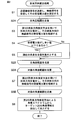
- FIG. 2 is a flowchart showing an arrival direction estimation process executed by the radar device 100 of FIG.
- step S1 of FIG. 2 the transmission wireless signal is transmitted, the wireless signal is received, and the received power value is measured and stored.
- steps S2A to S2B the entire angle range related to the directions of the transmitted radio signal and the received radio signal is changed by a predetermined change width and scanned, and the processes of steps S3 to S5 are executed.
- step S3 the arrival direction (DOA) is estimated by using, for example, the first arrival direction estimation method, which is the Beamformer method, and the received power value of the radio signal in the arrival direction is stored in the storage unit 10 together with the arrival direction. It is determined whether or not the received power value estimated in S4 is equal to or less than a predetermined threshold value. If YES in step S4, the process proceeds to step S5 and the current angle is excluded from the scanning target, while if NO, the process proceeds to step S2B.
- step S7 the arrival direction (DOA) is estimated by using, for example, the second arrival direction estimation method, which is the MUSIC method, and the received power value of the radio signal in the arrival direction is stored in the storage unit 10 together with the arrival direction.
- the second arrival direction estimation method is an arrival direction estimation method having a resolution higher than that of the first arrival direction estimation method.
- step S8 the angle information of the target 20 is extracted and output from the angle spectrum by the second arrival direction estimation method.
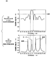
- FIG. 3 is a graph showing the received power value with respect to the arrival angle (DOA) showing the execution result executed by the arrival direction estimation process of FIG.
- the threshold value is set to ⁇ 10 dB from the arrival direction estimation result of the Beamformer method, and an angle range having a power value equal to or higher than the threshold value is extracted.
- the magnitude of the threshold value can be freely set according to the SN ratio.
- FIG. 3B by executing the arrival direction estimation process using the MUSIC method only in the angle range extracted above, the false image is suppressed and only the arrival direction of only the target is extracted. can do. As a result, the processing time can be significantly shortened, and accurate target arrival direction information can be obtained.
- the target existed even at an angle where the received power value was low.
- the target can be targeted at the angle where the received power is low in the arrival direction estimation process using the MUSIC method in the subsequent stage. It will not be judged to exist.
- the MUSIC method was applied to the entire angle range, but according to this embodiment, the processing time can be significantly shortened by limiting the angle range to be scanned by the MUSIC method.
- the processing of the Beamformer method is added in this embodiment, but the calculation time of the Beamformer method is smaller than the calculation time of the MUSIC method. Therefore, although it depends on the situation, the effect of reducing the scanning range of the MUSIC method is greater than the addition of the arrival direction estimation processing of the Beamformer method, and it can be expected that the processing time will be shortened as a whole.
- Accurate target detection can be performed by obtaining the actual target angle information instead of the false image angle information.
- the target can be detected in a finer cycle. This makes it easier for higher-level applications to accurately track the target.
- the received power value of the received radio signal is measured, but the present invention is not limited to this, and the received signal level such as the received signal strength (RSSI) may be measured.
- RSSI received signal strength
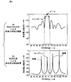
- FIG. 4 is a graph showing the received power value with respect to the arrival angle (DOA) showing the execution result executed by the arrival direction estimation process according to the modified example.
- the angle at which the received power value when the first arrival direction estimation method is used is equal to or less than a predetermined threshold value is excluded from the scanning target, and the second arrival direction is excluded.
- the arrival direction estimation process is performed using the estimation method.
- the range of the main beam having the maximum peak value of the received power value when the first arrival direction estimation method is used (as shown in FIG. 4, the maximum).
- the second arrival direction excludes the angle range other than the angle range between the two angles when the scanning angle becomes the minimum value when the scanning angle is changed by a predetermined value from the peak value angle to plus and minus).
- the arrival direction estimation process is performed using the estimation method. That is, the scanning angle range used in the arrival direction estimation process using the second arrival direction estimation method is limited.
- the Beamformer method is used as the first arrival direction estimation method
- the MUSIC method is used as the second arrival direction estimation method.
- the present invention is not limited to this, and the second method is not limited to this.
- the arrival direction estimation method is an arrival direction estimation method having a higher resolution than the resolution of the first arrival direction estimation method
- a combination of the other arrival direction estimation methods in Table 1 below may be used.
- the pattern 4 is the pattern of the embodiment.
- the Capon method is an algorithm that improves the drawbacks of the Beamformer method, which receives other waves in the side lobes, and aims the main lobe in one direction while minimizing the contribution to the output from the other direction. Therefore, a more accurate arrival direction is required as compared with the Beamformer method.
- the linear prediction method is a method of estimating the arrival direction toward the arrival wave.
- the resolution is determined by the beam width, whereas this method can estimate with a considerably high angular resolution, but this method also estimates the power by the same principle as DCMP (Directionally Constrained Minimization of Power). Is not as accurate as the Beamformer and Capon methods.
- the minimum norm method is a method of obtaining an angle spectrum by minimizing the output power under the condition that the norm of the weight vector is a constant value.
- the weight corresponds to selecting the eigenvector corresponding to the minimum eigenvalue among the K eigenvalues of the correlation matrix, and the output power is minimized.
- Non-Patent Document 1 the specific estimation process of these arrival direction estimation methods is disclosed in Non-Patent Document 1 and is known. As described above, the two arrival direction estimation processes may be used properly according to the desired resolution and processing time.
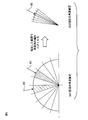
- FIG. 5 is a schematic view showing an arrival direction estimation process according to a conventional example disclosed in Patent Document 1.
- the conventional example is characterized in that the MUSIC method is divided into stages to estimate the angle. That is, as shown in FIG. 5A, first, the entire angle range is scanned with a large angle step width (for example, 10 °), and the peak is extracted. Next, as shown in FIG. 5 (b), the angle range corresponding to the extracted peak is specified, the application angle range is scanned with a smaller angle step width (for example, 1 °), and the peak is extracted. Further, the angle range corresponding to the peak extracted above is specified, and the applicable angle range is scanned with a smaller angle step width (for example, 0.1 °) to extract the peak.
- the conventional example is a method of repeating the calculation of the angle until a predetermined accuracy is reached in this way.
- the angle since the angle is estimated using only the MUSIC method, the occurrence of false images cannot be suppressed. For example, if a false image is extracted as a peak when scanning the entire angle range at the beginning, the angle calculation of the false image is repeated until the end.
- the angle since the angle is first estimated by using the Beamformer method, the occurrence of false images can be suppressed.
- the arrival direction estimation device and method according to the present invention it is possible to prevent the occurrence of false images and increase the number of targets.
- the arrival direction estimation device and method according to the present invention can be applied to a radar device or the like that senses the arrival direction of radio waves such as millimeter-wave radio waves.
- Transmission radio signal generator 1 Transmission radio signal generator 2 Power amplifier 3 Scanning transmission antenna 4 Scanning reception antenna 5 Low noise amplifier 6 Mixer 7 Filter 8 AD converter 9 Arrival direction analysis unit 10 Storage unit 11 Target determination unit 20 Target 30 Controller 31 Operation unit 32 Display
Landscapes
- Engineering & Computer Science (AREA)
- Computer Networks & Wireless Communication (AREA)
- Physics & Mathematics (AREA)
- General Physics & Mathematics (AREA)
- Radar, Positioning & Navigation (AREA)
- Remote Sensing (AREA)
- Radar Systems Or Details Thereof (AREA)
Abstract
受信方向を走査して無線信号を受信して前記無線信号の到来方向を推定する制御部を備えた到来方向推定装置が開示される。前記制御部は、第1の到来方向推定方法を用いて、受信した無線信号の到来方向を推定し、前記推定された無線信号の受信電力値のうち所定のしきい値以下の受信電力値を有する到来方向を有する無線信号を除外し、もしくは前記推定された無線信号の受信電力値のうち最大ピーク値を有するメインビームの範囲以外の到来方向を有する無線信号を除外し、前記第1の到来方向推定方法の分解能よりも高い分解能を有する第2の到来方向推定方法を用いて、受信した無線信号の到来方向を推定する。
Description
本発明は、例えばレーダ装置等のための、電波の到来方向を推定する到来方向推定装置及び方法に関する。
例えばミリ波レーダ装置を用いた、到来方向推定の従来技術として、MUSIC法(MUltiple Signal Classification)という手法が用いられている(例えば、特許文献1、非特許文献1参照)。
MUSIC法では、受信信号の自己相関行列の周波数成分を固有空間法によって推定することで、到来方向(DOA)を推定する。本手法では、ガウス分布のホワイトノイズ存在下に、p個の複素正弦波を含む次元Mの信号xを仮定し、これに対して、自己相関行列Rxを考える。自己相関行列Rxの固有値が降べきの順にソートされているとし、最初のp個の固有値に対応する固有ベクトル(すなわち、分散が大きな方向に対応する固有ベクトル)が張る部分空間を信号部分空間と呼ぶ。残りのM-p個の固有ベクトルは信号部分空間に直交する部分空間を張り、内部にはノイズのみが含まれている。MUSIC法は、このように信号部分空間とノイズの部分空間の直交性を利用して、p個の複素正弦波の到来方向を推定する手法である。
菊間信良,「アレーアンテナによる適応信号処理」,科学技術出版,2004年8月1日発行(9.1節~10.2節,173ページ~202ページ)
この手法は非常に高い分解能でターゲットの到来方向推定が可能であるが、本来ターゲットがない位置に偽像(スプリアス)が発生することがあり、課題となっていた。また、処理時間が長く、リアルタイムで用いる場合に同時に検出できるターゲットの数に限りがあるという課題もあった。
本発明の目的は以上の問題点を解決し、偽像の発生を防止することができ、しかもターゲットの数を増大できる到来方向推定装置及び方法を提供することにある。
第1の発明に係る到来方向推定装置は、
受信方向を走査して無線信号を受信して前記無線信号の到来方向を推定する制御部を備えた到来方向推定装置であって、
前記制御部は、
第1の到来方向推定方法を用いて、受信した無線信号の到来方向を推定し、
前記推定された無線信号の受信電力値のうち所定のしきい値以下の受信電力値を有する到来方向を有する無線信号を除外し、もしくは前記推定された無線信号の受信電力値のうち最大ピーク値を有するメインビームの範囲以外の到来方向を有する無線信号を除外し、前記第1の到来方向推定方法の分解能よりも高い分解能を有する第2の到来方向推定方法を用いて、受信した無線信号の到来方向を推定する。
受信方向を走査して無線信号を受信して前記無線信号の到来方向を推定する制御部を備えた到来方向推定装置であって、
前記制御部は、
第1の到来方向推定方法を用いて、受信した無線信号の到来方向を推定し、
前記推定された無線信号の受信電力値のうち所定のしきい値以下の受信電力値を有する到来方向を有する無線信号を除外し、もしくは前記推定された無線信号の受信電力値のうち最大ピーク値を有するメインビームの範囲以外の到来方向を有する無線信号を除外し、前記第1の到来方向推定方法の分解能よりも高い分解能を有する第2の到来方向推定方法を用いて、受信した無線信号の到来方向を推定する。
第2の発明に係る到来方向推定方法は、
受信方向を走査して無線信号を受信して前記無線信号の到来方向を推定する制御部を備えた到来方向推定装置のための到来方向推定方法であって、
前記制御部が、第1の到来方向推定方法を用いて、受信した無線信号の到来方向を推定するステップと、
前記制御部が、前記推定された無線信号の受信電力値のうち所定のしきい値以下の受信電力値を有する到来方向を有する無線信号を除外し、もしくは前記推定された無線信号の受信電力値のうち最大ピーク値を有するメインビームの範囲以外の到来方向を有する無線信号を除外し、前記第1の到来方向推定方法の分解能よりも高い分解能を有する第2の到来方向推定方法を用いて、受信した無線信号の到来方向を推定するステップとを含む。
受信方向を走査して無線信号を受信して前記無線信号の到来方向を推定する制御部を備えた到来方向推定装置のための到来方向推定方法であって、
前記制御部が、第1の到来方向推定方法を用いて、受信した無線信号の到来方向を推定するステップと、
前記制御部が、前記推定された無線信号の受信電力値のうち所定のしきい値以下の受信電力値を有する到来方向を有する無線信号を除外し、もしくは前記推定された無線信号の受信電力値のうち最大ピーク値を有するメインビームの範囲以外の到来方向を有する無線信号を除外し、前記第1の到来方向推定方法の分解能よりも高い分解能を有する第2の到来方向推定方法を用いて、受信した無線信号の到来方向を推定するステップとを含む。
従って、本発明に係る到来方向推定装置及び方法によれば、偽像の発生を防止することができ、しかもターゲットの数を増大できる。
以下、本発明にかかる実施形態について図面を参照して説明する。なお、同一又は同様の構成要素については同一の符号を付している。
(実施形態)
本実施形態ではMUSIC法に加えてBeamformer法という到来方向推定技術を用いる。Beamformer法は、MUSIC法と比較して、分解能は低いが、偽像が発生しづらく、処理時間も短いという特徴がある。
本実施形態ではMUSIC法に加えてBeamformer法という到来方向推定技術を用いる。Beamformer法は、MUSIC法と比較して、分解能は低いが、偽像が発生しづらく、処理時間も短いという特徴がある。
Beamformer法はもっとも基本的で伝統的な到来方向推定アルゴリズムであって、一様励振(uniform)アレーアンテナのメインローブ(メインビーム)を全方向にわたって走査しアレーの出力電力が大きくなる到来方向(DOA)を探す方法である。アレーアンテナのメインローブを角度θに向けるためには共相条件(同相になるように位相を揃える条件)より各ウェイトを所定値に設定すればよい。そして、角度θを-90度から+90度まで変化させ、アレーアンテナの出力電力のピークを探す。ここで、受信信号の相関行列Rxxとモードベクトルa(θ)を用いて角度スペクトラムPBF(θ)を構成し,角度θを変化させたときの角度スペクトラムPBF(θ)のピークの位置から到来方向が分かり、ピークの高さから到来波の入力電力を知ることができる。
本実施形態では、以下の手順により到来方向推定を行うことを特徴としている。
(1)Beamformer法により到来方向推定を行う。
(2)到来方向推定結果から、あらかじめ設定しておいたしきい値以上の受信電力を持つ角度を抽出する。
(3)抽出した角度において、MUSIC法により到来方向推定を行う。
(1)Beamformer法により到来方向推定を行う。
(2)到来方向推定結果から、あらかじめ設定しておいたしきい値以上の受信電力を持つ角度を抽出する。
(3)抽出した角度において、MUSIC法により到来方向推定を行う。
図1は実施形態に係る到来方向推定装置を備えたレーダ装置100の構成例を示すブロック図である。
図1において、レーダ装置100は、送信無線信号発生部1と、電力増幅器2と、走査型送信アンテナ3と、走査型受信アンテナ4と、低雑音増幅器5と、ミキサ6と、フィルタ7と、AD変換器8と、到来方向解析部9と、記憶部10と、ターゲット判定部11と、コントローラ30と、操作部31と、表示部32とを備えて構成される。
送信無線信号発生部1は所定の到来方向推定方法に対応するパルス変調方式で変調されたデータを含む送信無線信号を発生してミキサ6に出力するとともに、電力増幅器2を介して走査型送信アンテナ3に出力して、人体、動物又は車両等のターゲット20に向けて放射する。ここで、走査型送信アンテナ3はコントローラ30によりその指向性が走査されるように制御される。
ターゲット20により反射された反射無線信号は走査型受信アンテナ4で受信し、受信された受信無線信号は低雑音増幅器5を介してミキサ6に入力される。なお、走査型受信アンテナ4は反射無線信号以外の無線信号等の偽像(スプリアス)も受信する。ミキサ6は入力される送信無線信号と受信された無線信号とを混合して、混合結果の信号を例えばバンドパスフィルタ又はローパスフィルタなどのフィルタ7を介して所望のベースバンド信号を取り出して、AD変換器8に出力する。AD変換器8は入力されるベースバンド信号をデジタル信号にAD変換した後、到来方向解析部9に出力する。到来方向解析部9は、入力されるデジタル信号に基づいて、所定の到来方向推定方法に対応する到来方向推定処理を実行することで、1個又は複数の到来方向(DOA)とその受信電力値を含む到来方向推定結果データを得て、メモリにてなる記憶部10に一時的に格納する。ターゲット判定部11は記憶部10に格納された到来方向推定結果データに基づいて、所定の到来方向推定方法によりターゲット20であるか否かの判定を行ってコントローラ30に出力する。
コントローラ30には、指示データ等を入力する操作部31と、到来方向推定結果及びターゲット判定結果を表示する表示部32とが接続される。コントローラ30は、図2の到来方向推定処理を実行することで、ターゲット20で反射された無線信号の到来方向を推定する。
図2は図1のレーダ装置100により実行される到来方向推定処理を示すフローチャートである。
図2のステップS1において、送信無線信号を送信し、無線信号を受信してその受信電力値を測定して格納する。ステップS2A~S2Bでは、送信無線信号及び受信する無線信号の方向に係る全角度範囲を、所定の変化幅で変化させて走査してステップS3~S5の処理を実行する。ステップS3では、例えばBeamformer法である第1の到来方向推定方法を用いて到来方向(DOA)を推定し、その到来方向の無線信号の受信電力値を到来方向とともに記憶部10に格納し、ステップS4において推定された受信電力値が所定のしきい値以下であるか否かが判断される。ステップS4でYESのときはステップS5に進み現在の角度を走査対象外とする一方、NOのときはステップS2Bに進む。
次いで、ステップS6A~S6Bにおいて、送信無線信号及び受信する無線信号の方向に係る角度範囲であって、ステップS5で除外した角度を除く対象の角度範囲を、所定の変化幅で変化させて走査してステップS7の処理を実行する。ステップS7では、例えばMUSIC法である第2の到来方向推定方法を用いて到来方向(DOA)を推定し、その到来方向の無線信号の受信電力値を到来方向とともに記憶部10に格納する。ここで、第2の到来方向推定方法は、第1の到来方向推定方法の分解能よりも高い到来方向推定方法である。さらに、ステップS8では、第2の到来方向推定方法による角度スペクトラムからターゲット20の角度情報を抽出して出力する。
図3は図2の到来方向推定処理により実行された実行結果を示す到来角度(DOA)に対する受信電力値を示すグラフである。図3(a)に示すように、Beamformer法の到来方向推定結果からしきい値を-10dBと設定し、しきい値以上の電力値を持つ角度範囲を抽出する。ここで、しきい値の大きさはSN比に応じて自由に設定することが可能である。次いで、図3(b)に示すように、上記で抽出した角度範囲のみでMUSIC法を用いて到来方向推定処理を実行することで、偽像を抑制して、ターゲットのみの到来方向のみを抽出することができる。これにより、処理時間を大幅に短縮させ、正確なターゲットの到来方向の情報を得ることができる。
従来例のようにMUSIC法のみを用いて到来方向推定処理を実行すると、受信電力値が低い角度でもターゲットが存在すると判断することがあった。これに対して、本実施形態では、まずBeamformer法によって大域的に受信電力が高い角度を抽出しておくことで、後段のMUSIC法を用いた到来方向推定処理で受信電力が低い角度でターゲットが存在すると判断することがなくなる。
従来は全角度範囲に対してMUSIC法を適用していたが、本実施形態により、MUSIC法で走査する角度範囲を限定することで、処理時間を大幅に短縮できる。従来のMUSIC法のみの手法と比較して、本実施形態はBeamformer法の処理が加わっているが、Beamformer法の計算時間はMUSIC法の計算時間と比較して小さい。そのため、状況にもよるが、Beamformer法の到来方向推定処理が加わることよりも、MUSIC法の走査範囲を減らす効果の方が大きく、全体としては処理時間が短くなることが期待できる。
以上説明したように、本実施形態によれば、
(1)偽像の角度情報ではなく、実際のターゲットの角度情報を得ることにより、正確なターゲットの検知ができる。
(2)処理時間が短くなることにより、ターゲットをより細かい周期で検知することができる。これにより、上位のアプリケーションでターゲットを正確に追跡しやすくなる。
(1)偽像の角度情報ではなく、実際のターゲットの角度情報を得ることにより、正確なターゲットの検知ができる。
(2)処理時間が短くなることにより、ターゲットをより細かい周期で検知することができる。これにより、上位のアプリケーションでターゲットを正確に追跡しやすくなる。
(変形例)
以上の実施形態においては、受信した無線信号の受信電力値を測定しているが、本発明はこれに限らず、受信信号強度(RSSI)等の受信信号レベルを測定してもよい。
以上の実施形態においては、受信した無線信号の受信電力値を測定しているが、本発明はこれに限らず、受信信号強度(RSSI)等の受信信号レベルを測定してもよい。
図4は変形例に係る到来方向推定処理により実行された実行結果を示す到来角度(DOA)に対する受信電力値を示すグラフである。
前記実施形態では、図2のステップS4~S5では、第1の到来方向推定方法を用いたときの受信電力値が所定のしきい値以下である角度を走査対象外として、第2の到来方向推定方法を用いて到来方向推定処理を行っている。これに対して、この変形例に係る到来方向推定処理では、第1の到来方向推定方法を用いたときの受信電力値の最大ピーク値を有するメインビームの範囲(図4に示すように、最大ピーク値の角度から走査角度を所定値だけプラス及びマイナスに変化したときに極小値となるときの2つの角度間の角度範囲をいう)以外の角度範囲を走査対象外として、第2の到来方向推定方法を用いて到来方向推定処理を行う。すなわち、第2の到来方向推定方法を用いる到来方向推定処理で用いる走査角度範囲を限定する。
以上の実施形態及び変形例においては、第1の到来方向推定方法としてBeamformer法を用い、第2の到来方向推定方法としてMUSIC法を用いているが、本発明はこれに限らず、第2の到来方向推定方法が、第1の到来方向推定方法の分解能よりも高い到来方向推定方法であれば、以下の表1の他の到来方向推定方法の組み合わせを用いてもよい。なお、パターン4は前記実施形態のパターンである。
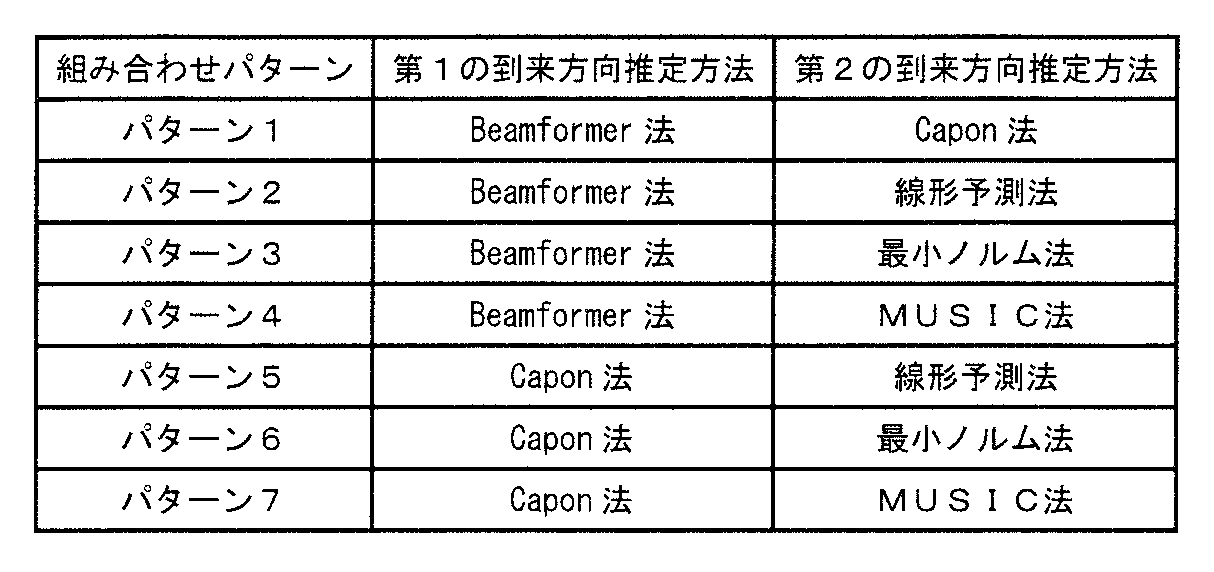
ここで、Capon法は、サイドローブで他の波を受けてしまうBeamformer法の欠点を改善したアルゴリズムで,ある方向にメインローブを向けると同時に他の方向からの出力への寄与を最小化することによりBeamformer法に比べより正確な到来方向が求められる。
また、線形予測(Linear Prediction)法は、ヌルを到来波に向けて到来方向推定する手法である。Beamformer法及びCapon法はビーム幅で分解能が決定してしまうのに対して、この手法はかなり高い角度分解能で推定できるが、この手法もDCMP(Directionally Constrained Minimization of Power)と同じ原理で,電力推定はBeamformer法及びCapon法ほど正確ではない。
さらに、最小ノルム法では,ウェイトベクトルのノルムを一定値とする条件の下で、出力電力を最小化することにより、角度スペクトラムを得る手法である。このとき、ウェイトは、相関行列のK個の固有値のうち最小固有値に対応する固有ベクトルを選択することに相当し、出力電力が最小化される。
なお、これらの到来方向推定方法の具体的な推定処理については、非特許文献1において開示されており公知である。以上説明したように、2つの到来方向推定処理については、所望の分解能や処理時間に応じて使い分けるとよい。
(特許文献1との相違点)
図5は、特許文献1で開示された従来例に係る到来方向推定処理を示す模式図である。
図5は、特許文献1で開示された従来例に係る到来方向推定処理を示す模式図である。
当該従来例はMUSIC法を段階的に分けて角度推定を行うことを特徴としている。すなわち、図5(a)に示すように、まず大きな角度刻み幅(例えば10°)で全角度範囲を走査し、ピークを抽出する。次に、図5(b)に示すように、抽出したピークに対応する角度範囲を指定し、より小さい角度刻み幅(例えば1°)で適用角度範囲を走査して、ピークを抽出する。さらに上記で抽出したピークに対応する角度範囲を指定し、さらに小さい角度刻み幅(例えば0.1°)で適用角度範囲を走査してピークを抽出する。従来例は、このようにして、所定の精度に達するまで角度の算出を繰り返す手法である。
従来例はMUSIC法のみを用いて角度推定を行っているため、偽像の発生を抑制できない。例えば、初めに全角度範囲を走査する際に、偽像をピークとして抽出してしまうと、最後まで偽像の角度算出を繰り返してしまう。一方、本実施形態では、上述したように、まずBeamformer法を用いて角度推定を行うため、偽像の発生を抑制できる。
以上詳述したように、本発明に係る到来方向推定装置及び方法によれば、偽像の発生を防止することができ、しかもターゲットの数を増大できる。本発明に係る到来方向推定装置及び方法は、例えばミリ波電波等の電波の到来方向をセンシングするレーダ装置等に適用できる。
1 送信無線信号発生部
2 電力増幅器
3 走査型送信アンテナ
4 走査型受信アンテナ
5 低雑音増幅器
6 ミキサ
7 フィルタ
8 AD変換器
9 到来方向解析部
10 記憶部
11 ターゲット判定部
20 ターゲット
30 コントローラ
31 操作部
32 表示部
2 電力増幅器
3 走査型送信アンテナ
4 走査型受信アンテナ
5 低雑音増幅器
6 ミキサ
7 フィルタ
8 AD変換器
9 到来方向解析部
10 記憶部
11 ターゲット判定部
20 ターゲット
30 コントローラ
31 操作部
32 表示部
Claims (17)
- 受信方向を走査して無線信号を受信して前記無線信号の到来方向を推定する制御部を備えた到来方向推定装置であって、
前記制御部は、
第1の到来方向推定方法を用いて、受信した無線信号の到来方向を推定し、
前記推定された無線信号の受信電力値のうち所定のしきい値以下の受信電力値を有する到来方向を有する無線信号を除外し、もしくは前記推定された無線信号の受信電力値のうち最大ピーク値を有するメインビームの範囲以外の到来方向を有する無線信号を除外し、前記第1の到来方向推定方法の分解能よりも高い分解能を有する第2の到来方向推定方法を用いて、受信した無線信号の到来方向を推定する、
到来方向推定装置。 - 前記第1の到来方向推定方法はBeamformer法であり、
前記第2の到来方向推定方法はMUSIC法である、
請求項1に記載の到来方向推定装置。 - 前記第1の到来方向推定方法はBeamformer法であり、
前記第2の到来方向推定方法はCapon法である、
請求項1に記載の到来方向推定装置。 - 前記第1の到来方向推定方法はBeamformer法であり、
前記第2の到来方向推定方法は線形予測法である、
請求項1に記載の到来方向推定装置。 - 前記第1の到来方向推定方法はBeamformer法であり、
前記第2の到来方向推定方法は最小ノルム法である、
請求項1に記載の到来方向推定装置。 - 前記第1の到来方向推定方法はCapon法であり、
前記第2の到来方向推定方法は線形予測法である、
請求項1に記載の到来方向推定装置。 - 前記第1の到来方向推定方法はCapon法であり、
前記第2の到来方向推定方法は最小ノルム法である、
請求項1に記載の到来方向推定装置。 - 前記第1の到来方向推定方法はCapon法であり、
前記第2の到来方向推定方法はMUSIC法である、
請求項1に記載の到来方向推定装置。 - 無線信号の放射方向を走査して前記無線信号を送信して、無線信号をその受信方向を走査して受信して前記無線信号の到来方向を推定するレーダ装置であって、
請求項1~8のうちのいずれか1つに記載の到来方向推定装置を備える、
レーダ装置。 - 受信方向を走査して無線信号を受信して前記無線信号の到来方向を推定する制御部を備えた到来方向推定装置のための到来方向推定方法であって、
前記制御部が、第1の到来方向推定方法を用いて、受信した無線信号の到来方向を推定するステップと、
前記制御部が、前記推定された無線信号の受信電力値のうち所定のしきい値以下の受信電力値を有する到来方向を有する無線信号を除外し、もしくは前記推定された無線信号の受信電力値のうち最大ピーク値を有するメインビームの範囲以外の到来方向を有する無線信号を除外し、前記第1の到来方向推定方法の分解能よりも高い分解能を有する第2の到来方向推定方法を用いて、受信した無線信号の到来方向を推定するステップとを含む、
到来方向推定方法。 - 前記第1の到来方向推定方法はBeamformer法であり、
前記第2の到来方向推定方法はMUSIC法である、
請求項10に記載の到来方向推定方法。 - 前記第1の到来方向推定方法はBeamformer法であり、
前記第2の到来方向推定方法はCapon法である、
請求項10に記載の到来方向推定方法。 - 前記第1の到来方向推定方法はBeamformer法であり、
前記第2の到来方向推定方法は線形予測法である、
請求項10に記載の到来方向推定方法。 - 前記第1の到来方向推定方法はBeamformer法であり、
前記第2の到来方向推定方法は最小ノルム法である、
請求項10に記載の到来方向推定方法。 - 前記第1の到来方向推定方法はCapon法であり、
前記第2の到来方向推定方法は線形予測法である、
請求項10に記載の到来方向推定方法。 - 前記第1の到来方向推定方法はCapon法であり、
前記第2の到来方向推定方法は最小ノルム法である、
請求項10に記載の到来方向推定方法。 - 前記第1の到来方向推定方法はCapon法であり、
前記第2の到来方向推定方法はMUSIC法である、
請求項10に記載の到来方向推定方法。
Priority Applications (2)
| Application Number | Priority Date | Filing Date | Title |
|---|---|---|---|
| PCT/JP2019/031448 WO2021024473A1 (ja) | 2019-08-08 | 2019-08-08 | 到来方向推定装置及び方法 |
| JP2021537533A JPWO2021024473A1 (ja) | 2019-08-08 | 2019-08-08 |
Applications Claiming Priority (1)
| Application Number | Priority Date | Filing Date | Title |
|---|---|---|---|
| PCT/JP2019/031448 WO2021024473A1 (ja) | 2019-08-08 | 2019-08-08 | 到来方向推定装置及び方法 |
Publications (1)
| Publication Number | Publication Date |
|---|---|
| WO2021024473A1 true WO2021024473A1 (ja) | 2021-02-11 |
Family
ID=74502555
Family Applications (1)
| Application Number | Title | Priority Date | Filing Date |
|---|---|---|---|
| PCT/JP2019/031448 Ceased WO2021024473A1 (ja) | 2019-08-08 | 2019-08-08 | 到来方向推定装置及び方法 |
Country Status (2)
| Country | Link |
|---|---|
| JP (1) | JPWO2021024473A1 (ja) |
| WO (1) | WO2021024473A1 (ja) |
Cited By (2)
| Publication number | Priority date | Publication date | Assignee | Title |
|---|---|---|---|---|
| WO2023218632A1 (ja) * | 2022-05-13 | 2023-11-16 | 株式会社日立製作所 | レーダ装置および物標検知方法 |
| US20250102664A1 (en) * | 2023-09-22 | 2025-03-27 | Robert Bosch Gmbh | Computer device and method for examining a radar system equipped with at least two transmitting and receiving units which each comprise at least one respective antenna element |
Citations (6)
| Publication number | Priority date | Publication date | Assignee | Title |
|---|---|---|---|---|
| JP2001091617A (ja) * | 1999-09-24 | 2001-04-06 | Toyota Central Res & Dev Lab Inc | ターゲット方位検出装置 |
| JP2006275840A (ja) * | 2005-03-30 | 2006-10-12 | Honda Elesys Co Ltd | 電子走査型ミリ波レーダ装置およびコンピュータプログラム |
| JP2008157823A (ja) * | 2006-12-25 | 2008-07-10 | Matsushita Electric Works Ltd | 測位方法及び測位装置 |
| JP2011163883A (ja) * | 2010-02-08 | 2011-08-25 | Honda Elesys Co Ltd | 電子走査型レーダ装置、受信波方向推定方法及び受信波方向推定プログラム |
| JP2013152239A (ja) * | 2013-03-29 | 2013-08-08 | Honda Elesys Co Ltd | 電子走査型レーダ装置、その制御方法及びプログラム |
| US20130322505A1 (en) * | 2012-06-01 | 2013-12-05 | Astrium Gmbh | Method of Detecting a Direction of Arrival of at Least One Interference Signal and System to Carry Out Said Method |
Family Cites Families (4)
| Publication number | Priority date | Publication date | Assignee | Title |
|---|---|---|---|---|
| JP2934426B1 (ja) * | 1998-02-09 | 1999-08-16 | 株式会社ワイ・アール・ピー移動通信基盤技術研究所 | 到来波推定方法 |
| JP2004108851A (ja) * | 2002-09-17 | 2004-04-08 | Toshiba Corp | 測角装置及びこの測角装置を用いた通信装置 |
| JP4271157B2 (ja) * | 2005-02-15 | 2009-06-03 | 株式会社東芝 | 到来方向推定装置及び到来方向推定方法 |
| JP2013238414A (ja) * | 2012-05-11 | 2013-11-28 | Honda Elesys Co Ltd | 車載用のレーダ装置、方位検知方法、方位検知プログラム |
-
2019
- 2019-08-08 JP JP2021537533A patent/JPWO2021024473A1/ja active Pending
- 2019-08-08 WO PCT/JP2019/031448 patent/WO2021024473A1/ja not_active Ceased
Patent Citations (6)
| Publication number | Priority date | Publication date | Assignee | Title |
|---|---|---|---|---|
| JP2001091617A (ja) * | 1999-09-24 | 2001-04-06 | Toyota Central Res & Dev Lab Inc | ターゲット方位検出装置 |
| JP2006275840A (ja) * | 2005-03-30 | 2006-10-12 | Honda Elesys Co Ltd | 電子走査型ミリ波レーダ装置およびコンピュータプログラム |
| JP2008157823A (ja) * | 2006-12-25 | 2008-07-10 | Matsushita Electric Works Ltd | 測位方法及び測位装置 |
| JP2011163883A (ja) * | 2010-02-08 | 2011-08-25 | Honda Elesys Co Ltd | 電子走査型レーダ装置、受信波方向推定方法及び受信波方向推定プログラム |
| US20130322505A1 (en) * | 2012-06-01 | 2013-12-05 | Astrium Gmbh | Method of Detecting a Direction of Arrival of at Least One Interference Signal and System to Carry Out Said Method |
| JP2013152239A (ja) * | 2013-03-29 | 2013-08-08 | Honda Elesys Co Ltd | 電子走査型レーダ装置、その制御方法及びプログラム |
Cited By (2)
| Publication number | Priority date | Publication date | Assignee | Title |
|---|---|---|---|---|
| WO2023218632A1 (ja) * | 2022-05-13 | 2023-11-16 | 株式会社日立製作所 | レーダ装置および物標検知方法 |
| US20250102664A1 (en) * | 2023-09-22 | 2025-03-27 | Robert Bosch Gmbh | Computer device and method for examining a radar system equipped with at least two transmitting and receiving units which each comprise at least one respective antenna element |
Also Published As
| Publication number | Publication date |
|---|---|
| JPWO2021024473A1 (ja) | 2021-02-11 |
Similar Documents
| Publication | Publication Date | Title |
|---|---|---|
| US10955542B2 (en) | Radar apparatus and direction-of-arrival estimation device | |
| JP5062225B2 (ja) | 物標検出装置 | |
| US8130147B2 (en) | Signal wave arrival angle measuring device | |
| US10523288B2 (en) | Wireless receiver, wireless receiving method, and wireless system | |
| KR100336550B1 (ko) | 방향 탐지기와 방향 탐지기의 측정 결과 처리 장치 | |
| JP6489589B2 (ja) | レーダ信号処理装置 | |
| CN113093173A (zh) | 实现迭代自适应方法(iaa)的波束成形技术 | |
| JP2019090749A (ja) | 到来方向推定装置および到来方向推定方法 | |
| KR20190134893A (ko) | 안테나 어레이 외삽을 이용한 레이더 수신신호의 도착방향 추정 방법 및 장치 | |
| US11874397B2 (en) | Radar device and signal processing method | |
| KR102158740B1 (ko) | 레이다 DoA 추정 시스템 및 방법 | |
| JP4187985B2 (ja) | 測角装置、測角方法及びプログラム | |
| JP4967218B2 (ja) | レーダ装置 | |
| JP6415392B2 (ja) | 信号処理装置 | |
| WO2019180767A1 (ja) | 物体検知装置、物体検知方法、及びコンピュータ読み取り可能な記録媒体 | |
| WO2018167952A1 (ja) | アダプティブアレーアンテナ装置 | |
| CN115542259B (zh) | 基于快速环境感知的机载雷达非均匀杂波抑制方法 | |
| JP2937174B2 (ja) | 方向探知装置 | |
| CN114609581B (zh) | 一种比较扫描方向矢量投影极大值的阵列超分辨测向方法 | |
| JP4119719B2 (ja) | 移動局方向推定方法及び装置 | |
| JP7597218B2 (ja) | 電波到来方向推定装置、電波到来方向推定方法、及び電波到来方向推定プログラム | |
| JP5025170B2 (ja) | 到来波数検出装置 | |
| JP7191262B1 (ja) | レーダ装置 | |
| JP3189826B2 (ja) | 方向探知装置 | |
| WO2021196165A1 (zh) | 频率分析方法、装置及雷达 |
Legal Events
| Date | Code | Title | Description |
|---|---|---|---|
| 121 | Ep: the epo has been informed by wipo that ep was designated in this application |
Ref document number: 19940674 Country of ref document: EP Kind code of ref document: A1 |
|
| ENP | Entry into the national phase |
Ref document number: 2021537533 Country of ref document: JP Kind code of ref document: A |
|
| NENP | Non-entry into the national phase |
Ref country code: DE |
|
| 122 | Ep: pct application non-entry in european phase |
Ref document number: 19940674 Country of ref document: EP Kind code of ref document: A1 |