WO2021024462A1 - データ収集システム、補助電源装置、モニタ装置およびデータ収集方法 - Google Patents
データ収集システム、補助電源装置、モニタ装置およびデータ収集方法 Download PDFInfo
- Publication number
- WO2021024462A1 WO2021024462A1 PCT/JP2019/031413 JP2019031413W WO2021024462A1 WO 2021024462 A1 WO2021024462 A1 WO 2021024462A1 JP 2019031413 W JP2019031413 W JP 2019031413W WO 2021024462 A1 WO2021024462 A1 WO 2021024462A1
- Authority
- WO
- WIPO (PCT)
- Prior art keywords
- power supply
- vehicle
- auxiliary power
- monitoring device
- supply device
- Prior art date
- Legal status (The legal status is an assumption and is not a legal conclusion. Google has not performed a legal analysis and makes no representation as to the accuracy of the status listed.)
- Ceased
Links
Images




Classifications
-
- G—PHYSICS
- G01—MEASURING; TESTING
- G01R—MEASURING ELECTRIC VARIABLES; MEASURING MAGNETIC VARIABLES
- G01R21/00—Arrangements for measuring electric power or power factor
- G01R21/06—Arrangements for measuring electric power or power factor by measuring current and voltage
-
- B—PERFORMING OPERATIONS; TRANSPORTING
- B61—RAILWAYS
- B61L—GUIDING RAILWAY TRAFFIC; ENSURING THE SAFETY OF RAILWAY TRAFFIC
- B61L15/00—Indicators provided on the vehicle or train for signalling purposes
- B61L15/0081—On-board diagnosis or maintenance
-
- B—PERFORMING OPERATIONS; TRANSPORTING
- B60—VEHICLES IN GENERAL
- B60L—PROPULSION OF ELECTRICALLY-PROPELLED VEHICLES; SUPPLYING ELECTRIC POWER FOR AUXILIARY EQUIPMENT OF ELECTRICALLY-PROPELLED VEHICLES; ELECTRODYNAMIC BRAKE SYSTEMS FOR VEHICLES IN GENERAL; MAGNETIC SUSPENSION OR LEVITATION FOR VEHICLES; MONITORING OPERATING VARIABLES OF ELECTRICALLY-PROPELLED VEHICLES; ELECTRIC SAFETY DEVICES FOR ELECTRICALLY-PROPELLED VEHICLES
- B60L1/00—Supplying electric power to auxiliary equipment of vehicles
-
- B—PERFORMING OPERATIONS; TRANSPORTING
- B60—VEHICLES IN GENERAL
- B60L—PROPULSION OF ELECTRICALLY-PROPELLED VEHICLES; SUPPLYING ELECTRIC POWER FOR AUXILIARY EQUIPMENT OF ELECTRICALLY-PROPELLED VEHICLES; ELECTRODYNAMIC BRAKE SYSTEMS FOR VEHICLES IN GENERAL; MAGNETIC SUSPENSION OR LEVITATION FOR VEHICLES; MONITORING OPERATING VARIABLES OF ELECTRICALLY-PROPELLED VEHICLES; ELECTRIC SAFETY DEVICES FOR ELECTRICALLY-PROPELLED VEHICLES
- B60L3/00—Electric devices on electrically-propelled vehicles for safety purposes; Monitoring operating variables, e.g. speed, deceleration or energy consumption
- B60L3/12—Recording operating variables ; Monitoring of operating variables
-
- B—PERFORMING OPERATIONS; TRANSPORTING
- B61—RAILWAYS
- B61L—GUIDING RAILWAY TRAFFIC; ENSURING THE SAFETY OF RAILWAY TRAFFIC
- B61L15/00—Indicators provided on the vehicle or train for signalling purposes
- B61L15/0058—On-board optimisation of vehicle or vehicle train operation
-
- B—PERFORMING OPERATIONS; TRANSPORTING
- B61—RAILWAYS
- B61L—GUIDING RAILWAY TRAFFIC; ENSURING THE SAFETY OF RAILWAY TRAFFIC
- B61L15/00—Indicators provided on the vehicle or train for signalling purposes
- B61L15/0094—Recorders on the vehicle
-
- G—PHYSICS
- G01—MEASURING; TESTING
- G01R—MEASURING ELECTRIC VARIABLES; MEASURING MAGNETIC VARIABLES
- G01R31/00—Arrangements for testing electric properties; Arrangements for locating electric faults; Arrangements for electrical testing characterised by what is being tested not provided for elsewhere
- G01R31/40—Testing power supplies
-
- B—PERFORMING OPERATIONS; TRANSPORTING
- B60—VEHICLES IN GENERAL
- B60L—PROPULSION OF ELECTRICALLY-PROPELLED VEHICLES; SUPPLYING ELECTRIC POWER FOR AUXILIARY EQUIPMENT OF ELECTRICALLY-PROPELLED VEHICLES; ELECTRODYNAMIC BRAKE SYSTEMS FOR VEHICLES IN GENERAL; MAGNETIC SUSPENSION OR LEVITATION FOR VEHICLES; MONITORING OPERATING VARIABLES OF ELECTRICALLY-PROPELLED VEHICLES; ELECTRIC SAFETY DEVICES FOR ELECTRICALLY-PROPELLED VEHICLES
- B60L2200/00—Type of vehicles
- B60L2200/26—Rail vehicles
Definitions
- the present invention relates to a data collection system, an auxiliary power supply device, a monitoring device, and a data collection method mounted on a railway vehicle.
- Patent Document 1 discloses a technique of reading and recording a signal including an operating status of a railway vehicle at a predetermined cycle.
- the recording device described in Patent Document 1 can stably record even in a situation where the state is unstable and difficult to grasp, such as when the power is turned on, by recording with a device equipped with a battery.
- the present invention has been made in view of the above, and an object of the present invention is to obtain a data collection system capable of recording the state of an in-vehicle device mounted on a railway vehicle at a desired timing.
- the present invention has a monitoring device for sequentially instructing a plurality of in-vehicle devices mounted on a railway vehicle to start and stop operations, and each of the monitoring devices is instructed. It is characterized by including an auxiliary power supply device that sequentially measures an output voltage and an output current when the in-vehicle devices are operating in sequence and records the measurement results.
- the data collection system has the effect of being able to record the state of the in-vehicle device mounted on the railroad vehicle at a desired timing.
- the figure which shows the example of the case where the processing circuit included in the auxiliary power supply device which concerns on Embodiment 1 is configured by a processor and a memory
- the figure which shows the example of the case where the processing circuit provided in the auxiliary power supply device which concerns on Embodiment 1 is configured by the dedicated hardware.
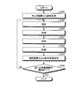
- a flowchart showing the operation of the monitoring device according to the second embodiment A flowchart showing the operation of the monitoring device according to the third embodiment.
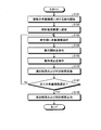
- a flowchart showing the operation of the auxiliary power supply device according to the fourth embodiment A flowchart showing the operation of the monitoring device according to the fourth embodiment.
- FIG. 1 is a diagram showing a configuration example of a train 7 including auxiliary power supply devices 1a and 1b and monitoring devices 2a and 2b according to the first embodiment of the present invention.
- the train 7 is composed of railroad vehicles 6a to 6f.
- the railway vehicle 6a is equipped with a monitor device 2a, a brake compressor 3a, and an air conditioner 4a.
- the railroad vehicle 6b is equipped with an auxiliary power supply device 1a, a brake compressor 3b, and an air conditioner 4b.
- the railroad vehicle 6c is equipped with a brake compressor 3c and an air conditioner 4c.
- the railroad vehicle 6d is equipped with a brake compressor 3d and an air conditioner 4d.
- the railroad vehicle 6e is equipped with an auxiliary power supply device 1b, a brake compressor 3e, and an air conditioner 4e.
- the railway vehicle 6f is equipped with a monitor device 2b, a brake compressor 3f, and an air conditioner 4f.
- the brake compressor is referred to as "CP".
- FIG. 1 the brake compressor
- the in-vehicle devices of the auxiliary power supply devices 1a and 1b, the monitor devices 2a and 2b, the brake compressors 3a to 3f, and the air conditioners 4a to 4f are connected by the communication line 5 and are connected via the communication line 5. It is possible to communicate with other in-vehicle devices.
- the train 7 has a redundant configuration including two auxiliary power supply devices 1a and 1b and two monitor devices 2a and 2b.
- the train 7 in operation at least one of the two auxiliary power supply devices 1a and 1b may be operating, and at least one of the two monitoring devices 2a and 2b may be operating.
- auxiliary power supply devices 1a and 1b when the auxiliary power supply devices 1a and 1b are not distinguished, they are referred to as the auxiliary power supply device 1, and when the monitor devices 2a and 2b are not distinguished, they are referred to as the monitor device 2.
- brake compressors 3a to 3f when the brake compressors 3a to 3f are not distinguished, they are referred to as brake compressors 3, when the air conditioners 4a to 4f are not distinguished, they are referred to as air conditioners 4, and when the railcars 6a to 6f are not distinguished, they are referred to as railways. It may be referred to as a vehicle 6.
- each railroad vehicle 6 of the train 7 may be equipped with an in-vehicle device other than the brake compressor 3 and the air conditioner 4.
- the train 7 is composed of a 6-car train, but this is an example and is not limited to this.
- the train 7 may be a train of 5 cars or less, or a train of 7 cars or more.
- the auxiliary power supply device 1 when the auxiliary power supply device 1 operates in cooperation with the monitor device 2 and operates each in-vehicle device at a specified timing or a timing specified by the user, the auxiliary power supply device 1 is used. Measure and record the output voltage and output current.
- the auxiliary power supply device 1 may measure the output voltage and the output current, and may simultaneously measure the temperature around the auxiliary power supply device 1 using a thermistor or the like (not shown). In this case, the auxiliary power supply 1 records the temperature in association with the output voltage and output current.
- the monitoring device 2 sequentially commands a plurality of in-vehicle devices mounted on the railway vehicle 6 to start and stop the operation.
- the auxiliary power supply device 1 sequentially measures the output voltage and the output current when each in-vehicle device is sequentially operating according to the command of the monitoring device 2, and records the measurement result which is the measurement result.
- the specific configuration and operation of the auxiliary power supply device 1 and the monitor device 2 will be described.
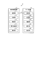
- FIG. 2 is a diagram showing a configuration example of the auxiliary power supply device 1 and the monitor device 2 according to the first embodiment.
- the data collection system 8 is composed of the auxiliary power supply device 1 and the monitor device 2.
- the auxiliary power supply device 1 includes a communication unit 11, a recording unit 12, a control unit 13, a power supply unit 14, and a measurement unit 15.
- the communication unit 11 communicates with the monitoring device 2 via the communication line 5.
- the existing communication method used in a general railway vehicle may be used.
- the recording unit 12 records the measurement result, which is the result measured by the measuring unit 15, and the information in the command order in which the monitoring device 2 commands a plurality of in-vehicle devices.
- the information in the order of commands is set by the user or the like and is recorded in the recording unit 12 in advance.
- the control unit 13 instructs the measurement unit 15 to measure the timing, and records the measurement result measured by the measurement unit 15 in the recording unit 12 based on the information in the command order.
- the power supply unit 14 supplies power to a plurality of in-vehicle devices. Actually, the power supply unit 14 converts the electric power acquired from the overhead wire (not shown) via the pantograph into electric power that can be used by a plurality of in-vehicle devices and supplies the electric power to each in-vehicle device.
- the measuring unit 15 sequentially measures the output voltage and the output current from the power supply unit 14 when each in-vehicle device is operating in sequence according to the command of the monitoring device 2.
- the monitoring device 2 includes a communication unit 21, a recording unit 22, a control unit 23, an operation unit 24, and a display unit 25.
- the communication unit 21 communicates with the auxiliary power supply device 1 and a plurality of in-vehicle devices via the communication line 5.
- the recording unit 22 records information in the order of commands that sequentially commands the start and stop of operations to a plurality of in-vehicle devices mounted on the railway vehicle 6.
- the information in the order of commands is set by the user or the like and is recorded in the recording unit 22 in advance.
- the control unit 23 sequentially commands a plurality of in-vehicle devices to start and stop operations based on the information in the command order recorded in the recording unit 22.
- the operation unit 24 receives an operation from the user, specifically, an instruction to start measurement for each in-vehicle device.
- the display unit 25 displays the operating status of a plurality of in-vehicle devices. In addition, the display unit 25 displays the measurement result acquired from the auxiliary power supply device 1.
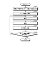
- FIG. 3 is a flowchart showing the operation of the monitoring device 2 according to the first embodiment.
- the control unit 23 starts commands to a plurality of in-vehicle devices when a specified event occurs, when there is an instruction from the user, or when there is an instruction from the auxiliary power supply device 1.
- the specified event is an operating condition in which the operating conditions of the in-vehicle device to be measured are specified when the power of the railway vehicle 6 is turned on, when the railway vehicle 6 is detained, or during the operation of the railway vehicle 6. If it matches.
- the specified event targeted by the monitoring device 2 may be referred to as a first event.
- the power of the railway vehicle 6 is turned on when the operation of the railway vehicle 6, that is, the train 7 is started.
- the case where the railroad vehicle 6 is detained is a case where the railroad vehicle 6, that is, the train 7 is temporarily detained on a detention line or the like after the start of operation and before the end of the operation on the day.
- the operating conditions of the in-vehicle device to be measured meet the specified operating conditions during the operation of the railroad vehicle 6, for example, the operating temperature of the railroad vehicle 6, that is, the train 7 is grasped when the operating state is low. Therefore, the temperature is below the set temperature, or above the set temperature for grasping the operating state at high temperature.
- the specified operating conditions may be set at a traveling point such as a sharp curve or a steep slope on which the train 7 travels.
- control unit 23 When the control unit 23 starts a command for a plurality of vehicle-mounted devices, the control unit 23 notifies the auxiliary power supply device 1 via the communication unit 21 that the command for the plurality of vehicle-mounted devices is started (step S102).
- the control unit 23 sets the vehicle-mounted devices in the command order based on the command order information recorded in the recording unit 22 that sequentially commands the start and stop of the operation of the plurality of vehicle-mounted devices mounted on the railway vehicle 6. Select (step S103).
- the information in the command order is, for example, air conditioner 4a ⁇ air conditioner 4b ⁇ air conditioner 4c ⁇ air conditioner 4d ⁇ air conditioner 4e ⁇ air conditioner 4f ⁇ brake compressor 3a ⁇ brake compressor 3b ⁇ brake
- the order is compressor 3c ⁇ brake compressor 3d ⁇ brake compressor 3e ⁇ brake compressor 3f.
- the control unit 23 selects in-vehicle devices one by one from the air conditioner 4a.
- the control unit 23 commands the selected in-vehicle device to start operation via the communication unit 21 (step S104).
- the control unit 23 first commands the air conditioner 4a to start operation.
- the control unit 23 commands the selected in-vehicle device to stop the operation via the communication unit 21 (step). S105).
- the control unit 23 receives from the auxiliary power supply device 1 via the communication unit 21 the measurement results of the output voltage and the output current with respect to the power output by the auxiliary power supply device 1 while the selected in-vehicle device is operating (step S106). ..
- the control unit 23 selects the next in-vehicle device according to the information in the command order (step S103). Subsequent operations are as described above.
- the control unit 23 outputs the received measurement result when all the in-vehicle devices are selected (step S107: Yes), that is, when the selection up to the brake compressor 3f is completed in the above example (step S108).
- the control unit 23 may display the measurement result on the display unit 25, or may transmit the measurement result to a ground device (not shown). Further, the control unit 23 may record the measurement result in the recording unit 22 so that the user can retrieve the measurement result from the recording unit 22 via a storage medium (not shown). That is, the control unit 23 executes at least one of recording the measurement result on the recording unit 22, displaying the measurement result on the display unit 25, and transmitting the measurement result to the ground device.
- control unit 23 may record information such as the running position of the train 7 and the ambient temperature of the train 7 on the recording unit 22 or the display unit 25 together with the measurement result. , May be transmitted to ground equipment.
- the monitoring device 2 does not receive the measurement result from the auxiliary power supply device 1 each time the operation of one in-vehicle device is completed, and in the case of step S107: Yes, the measurement result is collectively received from the auxiliary power supply device 1. You may try to do it.
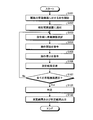
- FIG. 4 is a flowchart showing the operation of the auxiliary power supply device 1 according to the first embodiment.
- the control unit 13 receives a notification from the monitoring device 2 via the communication unit 11 to start a command to a plurality of in-vehicle devices (step S201)
- the railway vehicle 6 is transmitted from the recording unit 12.
- the control unit 13 controls the operation of the measurement unit 15 based on the information in the order of commands.
- the measuring unit 15 measures the output voltage and output current of the electric power output from the power supply unit 14 while the in-vehicle device selected by the monitoring device 2 is operating (step S202).
- the control unit 13 records the measurement results of the output voltage and the output current measured by the measurement unit 15 in the recording unit 12 (step S203).
- the control unit 13 transmits the measurement results of the output voltage and the output current measured by the measurement unit 15 and recorded in the recording unit 12 to the monitoring device 2 via the communication unit 11 (step S204).
- the format of the signal when the measurement result is transmitted from the auxiliary power supply device 1 to the monitor device 2 is set in advance by the user or the like in the auxiliary power supply device 1 and the monitor device 2.
- control unit 13 may transmit the measurement result to a ground device (not shown).
- the control unit 13 determines the output voltage and output current of the power output from the power supply unit 14 for the next in-vehicle device according to the information in the command order. Measure (step S202). Subsequent operations are as described above.
- step S205: Yes When the measurement of all the in-vehicle devices is completed (step S205: Yes), the control unit 13 ends the operation. It should be noted that the auxiliary power supply device 1 does not transmit the measurement result to the monitor device 2 every time the measurement for one in-vehicle device is completed, and in the case of step S205: Yes, the measurement results are collectively transmitted. Good.
- the auxiliary power supply device 1 can grasp the state of each in-vehicle device immediately before the start of operation by measuring a plurality of in-vehicle devices at the start of operation of the railway vehicle 6, that is, the train 7, and the in-vehicle device can be operated during operation. The possibility of failure can be reduced.
- the auxiliary power supply device 1 can acquire reference information for considering the maintenance menu for each in-vehicle device by measuring a plurality of in-vehicle devices when the railway vehicle 6, that is, the train 7 is detained. It is possible to realize labor saving in maintenance.
- the auxiliary power supply device 1 measures a plurality of in-vehicle devices to obtain actual operating conditions. Can be measured.
- the auxiliary power supply device 1 cooperates with the monitoring device 2 to perform measurement when the vehicle-mounted device is in a specific state, or to perform measurement under conditions such as a specific temperature where there is a high possibility of failure. It is possible to monitor the equipment intensively and collect information according to the needs of the operator.
- the auxiliary power supply device 1 measures only the specific in-vehicle device. May be good.
- the auxiliary power supply device 1 cannot specify which in-vehicle device has an abnormality.
- the auxiliary power supply device 1 can detect that an abnormality has occurred in any of the plurality of in-vehicle devices, it is possible to issue an alarm notifying the user or the like of a sign of failure. The user who notices the alarm can inspect the corresponding train 7 in detail.
- the data collection system 8 actively performs the measurement at regular intervals as compared with the case where the railroad vehicle 6 is actively operated. It is possible to grasp the state of the in-vehicle device mounted on the.
- the operating state of the train 7 in each pattern is different, so that the measurement result of the auxiliary power supply device 1 may differ depending on the pattern.
- the user may operate so as to determine whether or not an abnormality has occurred in the train 7 based on the measured value farthest from the measured value in the normal state.
- the communication unit 11 is a communication device.
- the recording unit 12 is a memory.
- the power supply unit 14 is a power conversion circuit.
- the measuring unit 15 is a measuring instrument capable of measuring voltage and current.
- the control unit 13 is realized by a processing circuit.
- the processing circuit may be a processor and memory for executing a program stored in the memory, or may be dedicated hardware.
- FIG. 5 is a diagram showing an example in which the processing circuit included in the auxiliary power supply device 1 according to the first embodiment is configured by a processor and a memory.
- the processing circuit is composed of the processor 91 and the memory 92, each function of the processing circuit of the auxiliary power supply device 1 is realized by software, firmware, or a combination of software and firmware.
- the software or firmware is written as a program and stored in the memory 92.
- each function is realized by the processor 91 reading and executing the program stored in the memory 92. That is, the processing circuit includes a memory 92 for storing a program in which the processing of the auxiliary power supply device 1 is eventually executed. It can also be said that these programs cause the computer to execute the procedure and method of the auxiliary power supply device 1.
- the processor 91 may be a CPU (Central Processing Unit), a processing device, an arithmetic unit, a microprocessor, a microcomputer, a DSP (Digital Signal Processor), or the like.
- the memory 92 includes, for example, non-volatile or volatile such as RAM (Random Access Memory), ROM (Read Only Memory), flash memory, EPROM (Erasable Programmable ROM), and EEPROM (registered trademark) (Electrically EPROM).
- RAM Random Access Memory
- ROM Read Only Memory
- flash memory e.g., EPROM (Erasable Programmable ROM), and EEPROM (registered trademark) (Electrically EPROM).
- Semiconductor memory magnetic disk, flexible disk, optical disk, compact disk, mini disk, DVD (Digital Versatile Disc), etc. are applicable.
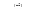
- FIG. 6 is a diagram showing an example in which the processing circuit included in the auxiliary power supply device 1 according to the first embodiment is configured by dedicated hardware.
- the processing circuit is composed of dedicated hardware
- the processing circuit 93 shown in FIG. 6 includes, for example, a single circuit, a composite circuit, a programmed processor, a parallel programmed processor, an ASIC (Application Specific Integrated Circuit), and the like. FPGA (Field Programmable Gate Array) or a combination of these is applicable.
- Each function of the auxiliary power supply device 1 may be realized by the processing circuit 93 for each function, or each function may be collectively realized by the processing circuit 93.
- a part may be realized by dedicated hardware and a part may be realized by software or firmware.
- the processing circuit can realize each of the above-mentioned functions by the dedicated hardware, software, firmware, or a combination thereof.
- the communication unit 21 is a communication device.
- the recording unit 22 is a memory.
- the operation unit 24 is an input interface such as a switch and a keyboard.
- the display unit 25 is a display such as an LCD (Liquid Crystal Display).
- the control unit 23 is realized by a processing circuit. As in the case of the auxiliary power supply device 1, the processing circuit may be a processor and a memory for executing a program stored in the memory, or may be dedicated hardware.
- the monitoring device 2 sequentially operates each in-vehicle device, and the auxiliary power supply device 1 operates each in-vehicle device. It was decided to measure and record the output voltage and output current from the auxiliary power supply device 1 inside. As a result, the auxiliary power supply device 1 can automatically record the state of the in-vehicle device mounted on the railway vehicle 6 at a desired timing. Further, the monitoring device 2 receives an operation from the user, specifically, an instruction to start measurement for each in-vehicle device, so that the auxiliary power supply device 1 is an in-vehicle device mounted on the railway vehicle 6 at a timing desired by the user. The state of can be recorded automatically. Further, when the monitoring device 2 displays the measurement result of the auxiliary power supply device 1, the user can monitor the state of a plurality of in-vehicle devices mounted on the train 7 in real time.
- Embodiment 2 In the first embodiment, the case where the auxiliary power supply device 1 performs the measurement with the monitoring device 2 as the starting point has been described. In the second embodiment, a case where the measurement is performed with the auxiliary power supply device 1 as the starting point will be described.
- the configuration of the train 7 is the same as that of the first embodiment shown in FIG.
- the configuration of the data collection system 8 is the same as that of the first embodiment shown in FIG.
- FIG. 7 is a flowchart showing the operation of the auxiliary power supply device 1 according to the second embodiment.
- the control unit 13 determines to start measurement for a plurality of in-vehicle devices when a specified event occurs (step S211).
- the specified event is when the power of the railroad vehicle 6 is turned on or when the railroad vehicle 6 is detained.
- the specified event targeted by the auxiliary power supply device 1 may be referred to as a second event.
- the control unit 13 notifies the monitoring device 2 of an instruction to start measurement for a plurality of vehicle-mounted devices via the communication unit 11 (step S212). Subsequent operations of steps S202 to S205 are the same as those of the first embodiment shown in FIG.
- FIG. 8 is a flowchart showing the operation of the monitoring device 2 according to the second embodiment.
- the control unit 23 obtains a notification from the auxiliary power supply device 1 via the communication unit 21 that the measurement for the plurality of in-vehicle devices has been decided (step S111). Subsequent operations of steps S103 to S108 are the same as those of the first embodiment shown in FIG.
- the auxiliary power supply device 1 is used as the starting point to measure the output voltage and the output current. Also in this case, the same effect as that of the first embodiment can be obtained.
- Embodiment 3 the monitoring device 2 determines whether or not the measurement result acquired from the auxiliary power supply device 1 is within the specified range.
- the first embodiment will be described as an example, the present invention can also be applied to the second embodiment.
- the configuration of the train 7 is the same as that of the first embodiment shown in FIG. Further, the configuration of the data collection system 8 is the same as that of the first embodiment shown in FIG.
- FIG. 9 is a flowchart showing the operation of the monitoring device 2 according to the third embodiment.
- the operation of steps S101 to S107 is the same as the operation of the first embodiment shown in FIG.
- the control unit 23 determines whether or not the measurement result received from the auxiliary power supply device 1 is within the specified range (step S121).
- the auxiliary power supply device 1 measures the output voltage and the output current during the operation of the brake compressor 3 and the air conditioner 4 mounted on the railroad vehicle 6, that is, the train 7.
- the brake compressor 3 and the air conditioner 4 it is possible to define the output voltage and output current range of the electric power output from the auxiliary power supply device 1 during normal operation.
- the monitoring device 2 has a range of the output voltage and output current of the auxiliary power supply device 1 assumed during the normal operation of the brake compressor 3, and the output voltage of the auxiliary power supply device 1 assumed during the normal operation of the air conditioner 4. Information on the range of the output current is recorded in the recording unit 22.
- the control unit 23 outputs the received measurement result and the determination result which is the determination result (step S122). For example, the control unit 23 may display the measurement result and the determination result on the display unit 25, or may transmit the measurement result and the determination result to a ground device (not shown). Further, the control unit 23 may record the measurement result and the determination result in the recording unit 22 so that the user can retrieve the measurement result and the determination result from the recording unit 22 via a storage medium (not shown). That is, at least the control unit 23 records the measurement result and the determination result on the recording unit 22, displays the measurement result and the determination result on the display unit 25, and transmits the measurement result and the determination result to the ground device. Do one.
- the operation of the auxiliary power supply device 1 is the same as the operation of the first embodiment shown in FIG.
- the monitoring device 2 determines whether the measurement result received from the auxiliary power supply device 1 is in a good state, that is, whether it is within a specified range. did. As a result, the monitoring device 2 can easily display to the user what state the plurality of in-vehicle devices mounted on the train 7 are in.
- the method of determining the measurement result in the control unit 23 of the monitoring device 2 may be performed by a method other than the measurement result within the specified range, that is, the comparison with the threshold value.
- the control unit 23 of the monitor device 2 may determine the measurement result from the shape of the waveform representing the output voltage and the output current in time series, or may use the past measurement result of the output voltage and the output current.
- the measurement result may be determined from the calculated distribution of singular values, or the measurement result may be determined from the inclination when the measurement result increases or decreases in time series.
- Embodiment 4 the auxiliary power supply device 1 determines whether or not the measurement result is within the specified range.
- the first embodiment will be described as an example, the present invention can also be applied to the second embodiment.
- the configuration of the train 7 is the same as that of the first embodiment shown in FIG. Further, the configuration of the data collection system 8 is the same as that of the first embodiment shown in FIG.
- FIG. 10 is a flowchart showing the operation of the auxiliary power supply device 1 according to the fourth embodiment.
- the operation of steps S201 to S203 is the same as the operation of the first embodiment shown in FIG.
- the control unit 13 determines whether or not the measurement result is within the specified range (step S231).
- the determination method in the control unit 13 is the same as the determination method in the control unit 23 of the monitoring device 2 of the third embodiment described above.
- the control unit 13 records the determination result, which is the determination result, in the recording unit 12 (step S232).
- the control unit 13 transmits the measurement result of the output voltage and the output current measured by the measurement unit 15 and the determination result to the monitoring device 2 via the communication unit 11 (step S233).
- the format of the signal when the measurement result and the determination result are transmitted from the auxiliary power supply device 1 to the monitor device 2 is set in advance by the user or the like in the auxiliary power supply device 1 and the monitor device 2.
- the control unit 13 may transmit the measurement result and the determination result to a ground device (not shown).
- the OK or NG information can be represented by one bit of information, that is, "0" or "1".
- FIG. 11 is a flowchart showing the operation of the monitoring device 2 according to the fourth embodiment.
- the operation of steps S101 to S105 is the same as the operation of the first embodiment shown in FIG.
- the control unit 23 defines the measurement results of the output voltage and the output current with respect to the power output by the auxiliary power supply device 1 while the selected in-vehicle device is operating from the auxiliary power supply device 1 and the measurement results via the communication unit 21.
- the determination result of whether or not it is within the above range is received (step S131).
- step S107 No
- the control unit 23 selects the next in-vehicle device according to the information in the command order (step S103). Subsequent operations are as described above.
- the control unit 23 outputs the received measurement result and determination result when all the in-vehicle devices are selected (step S107: Yes), that is, when the selection up to the brake compressor 3f is completed in the above example (step S132). ..
- the control unit 23 may display the measurement result and the determination result on the display unit 25, or may transmit the measurement result and the determination result to a ground device (not shown). Further, the control unit 23 may record the measurement result and the determination result in the recording unit 22 so that the user can retrieve the measurement result and the determination result from the recording unit 22 via a storage medium (not shown).
- control unit 23 records the measurement result and the determination result on the recording unit 22, displays the measurement result and the determination result on the display unit 25, and transmits the measurement result and the determination result to the ground device. Do one.
- the control unit 23 may record information such as the running position of the train 7 and the temperature around the train 7 on the recording unit 22 as well as the measurement result and the determination result, or display the information on the display unit 25. It may be transmitted to a ground device.
- the auxiliary power supply device 1 determines whether the measurement result is in a good state, that is, whether it is within the specified range, and transmits the determination result to the monitor device 2. I decided to send it. Also in this case, the same effect as that of the third embodiment can be obtained.
- the configuration shown in the above-described embodiment shows an example of the content of the present invention, can be combined with another known technique, and is one of the configurations without departing from the gist of the present invention. It is also possible to omit or change the part.
- 1,1a, 1b auxiliary power supply device 1,2a, 2b monitor device, 3a to 3f brake compressor, 4a to 4f air conditioner, 5 communication line, 6a to 6f railroad vehicle, 7 train, 8 data collection system, 11,21 Communication unit, 12, 22 recording unit, 13, 23 control unit, 14 power supply unit, 15 measurement unit, 24 operation unit, 25 display unit.
Landscapes
- Engineering & Computer Science (AREA)
- Mechanical Engineering (AREA)
- Power Engineering (AREA)
- Physics & Mathematics (AREA)
- General Physics & Mathematics (AREA)
- Transportation (AREA)
- Sustainable Energy (AREA)
- Sustainable Development (AREA)
- Life Sciences & Earth Sciences (AREA)
- Health & Medical Sciences (AREA)
- Biomedical Technology (AREA)
- General Health & Medical Sciences (AREA)
- Electric Propulsion And Braking For Vehicles (AREA)
Abstract
Description
図1は、本発明の実施の形態1に係る補助電源装置1a,1bおよびモニタ装置2a,2bを備えた列車7の構成例を示す図である。列車7は、鉄道車両6a~6fによって構成されている。
実施の形態1では、モニタ装置2が起点となって補助電源装置1が測定を行う場合について説明した。実施の形態2では、補助電源装置1が起点となって測定を行う場合について説明する。
実施の形態3では、モニタ装置2が、補助電源装置1から取得した測定結果が規定された範囲内にあるか否かを判定する。実施の形態1を例にして説明するが、実施の形態2にも適用可能である。
実施の形態4では、補助電源装置1が、測定結果が規定された範囲内にあるか否かを判定する。実施の形態1を例にして説明するが、実施の形態2にも適用可能である。
Claims (20)
- 鉄道車両に搭載された複数の車載機器に対して動作の開始および停止を順次指令するモニタ装置と、
前記モニタ装置の指令によって各車載機器が順番に動作しているときの、出力電圧および出力電流を順次測定し、測定結果を記録する補助電源装置と、
を備えることを特徴とするデータ収集システム。 - 前記モニタ装置は、規定された第1のイベントが発生した場合、またはユーザからの指示があった場合、または前記補助電源装置からの指示があった場合、前記複数の車載機器に対する指令を開始する、
ことを特徴とする請求項1に記載のデータ収集システム。 - 前記第1のイベントは、前記鉄道車両の電源が投入された場合、または前記鉄道車両が留置された場合、または前記鉄道車両の運用中において測定対象の車載機器の動作条件が規定された動作条件に合致した場合である、
ことを特徴とする請求項2に記載のデータ収集システム。 - 前記補助電源装置は、規定された第2のイベントが発生した場合、前記モニタ装置に対して、前記複数の車載機器に対する指令の開始を指示する、
ことを特徴とする請求項1に記載のデータ収集システム。 - 前記第2のイベントは、前記鉄道車両の電源が投入された場合、または前記鉄道車両が留置された場合である、
ことを特徴とする請求項4に記載のデータ収集システム。 - 前記補助電源装置は、前記測定結果を前記モニタ装置に送信し、
前記モニタ装置は、前記測定結果を記録する、前記測定結果を表示する、および前記測定結果を地上装置に送信する、のうち少なくとも1つを実施する、
ことを特徴とする請求項1から5のいずれか1つに記載のデータ収集システム。 - 前記モニタ装置は、前記測定結果が規定された範囲内か否かを判定し、判定結果を記録する、前記判定結果を表示する、および前記判定結果を地上装置に送信する、のうち少なくとも1つを実施する、
ことを特徴とする請求項6に記載のデータ収集システム。 - 前記補助電源装置は、前記測定結果が規定された範囲内か否かを判定し、判定結果を前記モニタ装置に送信し、
前記モニタ装置は、前記判定結果を記録する、前記判定結果を表示する、および前記判定結果を地上装置に送信する、のうち少なくとも1つを実施する、
ことを特徴とする請求項6に記載のデータ収集システム。 - 鉄道車両に搭載された複数の車載機器に対して動作の開始および停止を順次指令するモニタ装置との間で通信を行う通信部と、
前記複数の車載機器に対して電力を供給する電力供給部と、
前記モニタ装置の指令によって各車載機器が順番に動作しているときの、前記電力供給部からの出力電圧および出力電流を順次測定する測定部と、
前記測定部において測定された結果である測定結果、および前記モニタ装置が前記複数の車載機器に指令する指令順の情報が記録される記録部と、
前記測定部に対して測定のタイミングを指示し、前記指令順の情報に基づいて、前記測定部で測定された前記測定結果を前記記録部に記録する制御部と、
を備えることを特徴とする補助電源装置。 - 前記制御部は、規定されたイベントが発生した場合、前記モニタ装置に対して、前記複数の車載機器に対する指令の開始を指示する、
ことを特徴とする請求項9に記載の補助電源装置。 - 前記イベントは、前記鉄道車両の電源が投入された場合、または前記鉄道車両が留置された場合である、
ことを特徴とする請求項10に記載の補助電源装置。 - 前記制御部は、前記記録部に記録されている前記測定結果を、前記通信部を介して前記モニタ装置に送信する、
ことを特徴とする請求項9から11のいずれか1つに記載の補助電源装置。 - 前記制御部は、前記測定結果が規定された範囲内か否かを判定し、判定結果を、前記通信部を介して前記モニタ装置に送信する、
ことを特徴とする請求項12に記載の補助電源装置。 - 鉄道車両に搭載された複数の車載機器に対して動作の開始および停止を順次指令する指令順の情報が記録される記録部と、
前記指令順の情報に基づいて、前記複数の車載機器に対して動作の開始および停止を順次指令する制御部と、
各車載機器が順番に動作しているときの出力電圧および出力電流を順次測定して測定結果を記録する補助電源装置との間で通信を行う通信部と、
を備えることを特徴とするモニタ装置。 - 前記制御部は、規定されたイベントが発生した場合、またはユーザからの指示があった場合、または前記補助電源装置からの指示があった場合、前記複数の車載機器に対する指令を開始する、
ことを特徴とする請求項14に記載のモニタ装置。 - 前記イベントは、前記鉄道車両の電源が投入された場合、または前記鉄道車両が留置された場合、または前記鉄道車両の運用中において測定対象の車載機器の動作条件が規定された動作条件に合致した場合である、
ことを特徴とする請求項15に記載のモニタ装置。 - 前記制御部は、前記通信部を介して前記補助電源装置から前記測定結果を受信し、前記測定結果を前記記録部に記録する、前記測定結果を表示部に表示する、および前記測定結果を地上装置に送信する、のうち少なくとも1つを実施する、
ことを特徴とする請求項14から16のいずれか1つに記載のモニタ装置。 - 前記制御部は、前記測定結果が規定された範囲内か否かを判定し、判定結果を前記記録部に記録する、前記判定結果を表示部に表示する、および前記判定結果を地上装置に送信する、のうち少なくとも1つを実施する、
ことを特徴とする請求項17に記載のモニタ装置。 - 前記制御部は、前記通信部を介して前記補助電源装置から前記測定結果が規定された範囲内か否かを判定した判定結果を受信し、前記判定結果を前記記録部に記録する、前記判定結果を表示部に表示する、および前記判定結果を地上装置に送信する、のうち少なくとも1つを実施する、
ことを特徴とする請求項17に記載のモニタ装置。 - モニタ装置が、鉄道車両に搭載された複数の車載機器に対して動作の開始および停止を順次指令する指令ステップと、
補助電源装置が、前記モニタ装置の指令によって各車載機器が順番に動作しているときの、出力電圧および出力電流を順次測定し、測定結果を記録する測定ステップと、
を含むことを特徴とするデータ収集方法。
Priority Applications (4)
| Application Number | Priority Date | Filing Date | Title |
|---|---|---|---|
| JP2021538654A JP7126620B2 (ja) | 2019-08-08 | 2019-08-08 | データ収集システム、補助電源装置、モニタ装置およびデータ収集方法 |
| PCT/JP2019/031413 WO2021024462A1 (ja) | 2019-08-08 | 2019-08-08 | データ収集システム、補助電源装置、モニタ装置およびデータ収集方法 |
| US17/632,570 US12282048B2 (en) | 2019-08-08 | 2019-08-08 | Data collection system, auxiliary power supply, and monitoring device |
| DE112019007618.3T DE112019007618T5 (de) | 2019-08-08 | 2019-08-08 | Datensammelsystem, hilfsenergieversorgung, überwachungsvorrichtung und datensammelverfahren |
Applications Claiming Priority (1)
| Application Number | Priority Date | Filing Date | Title |
|---|---|---|---|
| PCT/JP2019/031413 WO2021024462A1 (ja) | 2019-08-08 | 2019-08-08 | データ収集システム、補助電源装置、モニタ装置およびデータ収集方法 |
Publications (1)
| Publication Number | Publication Date |
|---|---|
| WO2021024462A1 true WO2021024462A1 (ja) | 2021-02-11 |
Family
ID=74502896
Family Applications (1)
| Application Number | Title | Priority Date | Filing Date |
|---|---|---|---|
| PCT/JP2019/031413 Ceased WO2021024462A1 (ja) | 2019-08-08 | 2019-08-08 | データ収集システム、補助電源装置、モニタ装置およびデータ収集方法 |
Country Status (4)
| Country | Link |
|---|---|
| US (1) | US12282048B2 (ja) |
| JP (1) | JP7126620B2 (ja) |
| DE (1) | DE112019007618T5 (ja) |
| WO (1) | WO2021024462A1 (ja) |
Citations (3)
| Publication number | Priority date | Publication date | Assignee | Title |
|---|---|---|---|---|
| JP2011078174A (ja) * | 2009-09-29 | 2011-04-14 | Hitachi Ltd | 電池制御装置 |
| WO2014027400A1 (ja) * | 2012-08-14 | 2014-02-20 | 三菱電機株式会社 | 列車情報管理装置および機器制御方法 |
| WO2015136628A1 (ja) * | 2014-03-11 | 2015-09-17 | 三菱電機株式会社 | 列車情報管理装置 |
Family Cites Families (12)
| Publication number | Priority date | Publication date | Assignee | Title |
|---|---|---|---|---|
| JP3577265B2 (ja) * | 2000-07-21 | 2004-10-13 | 三菱電機株式会社 | モニタリングシステム |
| US7808195B2 (en) * | 2006-05-15 | 2010-10-05 | Mitsubishi Electric Corporation | Control apparatus for electric train |
| US7719134B2 (en) * | 2007-06-12 | 2010-05-18 | Mitsubishi Electric Corporation | In-vehicle mount electronic controller |
| EP2340957B1 (en) * | 2008-10-23 | 2018-08-29 | Mitsubishi Electric Corporation | Propulsion control device for electric car |
| US8892277B2 (en) * | 2009-07-22 | 2014-11-18 | Mitsubishi Electric Corporation | Vehicle air-conditioning control method |
| BR112013010381A2 (pt) * | 2010-11-05 | 2016-08-02 | Mitsubishi Electric Corp | dispositivo de controle do sistema de veículo |
| JP5492051B2 (ja) | 2010-11-08 | 2014-05-14 | 株式会社東芝 | 鉄道車両の記録装置 |
| KR101098044B1 (ko) | 2010-12-21 | 2011-12-23 | 한국철도기술연구원 | 철도차량 보조전원장치의 품질이상예측 시스템 및 방법 |
| WO2015019405A1 (ja) * | 2013-08-05 | 2015-02-12 | 三菱電機株式会社 | 電気車制御システムおよび電力変換装置 |
| KR101575518B1 (ko) * | 2014-08-20 | 2015-12-08 | 부산교통공사 | 전동차 주공기 압축기 기동장치 시험기 및 시험 방법 |
| US20160129925A1 (en) * | 2014-11-10 | 2016-05-12 | Caterpillar Inc. | Fuel control strategy for locomotive consist |
| JP6203432B2 (ja) * | 2015-01-20 | 2017-09-27 | 三菱電機株式会社 | ソフトウェア生成装置 |
-
2019
- 2019-08-08 WO PCT/JP2019/031413 patent/WO2021024462A1/ja not_active Ceased
- 2019-08-08 JP JP2021538654A patent/JP7126620B2/ja active Active
- 2019-08-08 DE DE112019007618.3T patent/DE112019007618T5/de active Pending
- 2019-08-08 US US17/632,570 patent/US12282048B2/en active Active
Patent Citations (3)
| Publication number | Priority date | Publication date | Assignee | Title |
|---|---|---|---|---|
| JP2011078174A (ja) * | 2009-09-29 | 2011-04-14 | Hitachi Ltd | 電池制御装置 |
| WO2014027400A1 (ja) * | 2012-08-14 | 2014-02-20 | 三菱電機株式会社 | 列車情報管理装置および機器制御方法 |
| WO2015136628A1 (ja) * | 2014-03-11 | 2015-09-17 | 三菱電機株式会社 | 列車情報管理装置 |
Also Published As
| Publication number | Publication date |
|---|---|
| US20220221496A1 (en) | 2022-07-14 |
| JPWO2021024462A1 (ja) | 2021-02-11 |
| JP7126620B2 (ja) | 2022-08-26 |
| US12282048B2 (en) | 2025-04-22 |
| DE112019007618T5 (de) | 2022-04-28 |
Similar Documents
| Publication | Publication Date | Title |
|---|---|---|
| CN104661891B (zh) | 用于对轨道交通的铁路网络的铁路部件进行诊断的方法 | |
| CN101903786B (zh) | 基于远程信息处理的用于车队的电池寄生负载确认的方法和系统 | |
| JP2743686B2 (ja) | 電気自動車用バッテリー充電装置 | |
| CN103548197A (zh) | 蓄电池监视方法、蓄电池监视系统以及蓄电池系统 | |
| CN114115172A (zh) | 车辆故障诊断方法、装置、可读存储介质及车辆 | |
| TW201520955A (zh) | 充電系統 | |
| JPWO2011037257A1 (ja) | 電池システム | |
| WO2007091710A1 (ja) | ハイブリッド車用電池寿命評価装置 | |
| JP6433710B2 (ja) | 車両システムおよびその制御方法 | |
| EP3936367A1 (en) | System and method for managing battery of vehicle | |
| CN104768828A (zh) | 用于计算轨道车辆的驾驶建议的方法、轨道车辆的辅助系统和轨道车辆 | |
| JP6732140B2 (ja) | 鉄道車両用記録装置、鉄道車両用空気調和装置、及び鉄道車両用記録方法 | |
| US6850035B2 (en) | Control system and method for battery control unit | |
| CN115359585A (zh) | 车辆提前排查故障的方法、装置、车辆及存储介质 | |
| JP2021189924A (ja) | 検修管理システム、検修管理サーバおよび検修管理方法 | |
| WO2021024462A1 (ja) | データ収集システム、補助電源装置、モニタ装置およびデータ収集方法 | |
| CN117944404A (zh) | 监测轮胎的方法、装置、电子设备及可读存储介质 | |
| JP2005271910A (ja) | 車輪の車輪特性量を監視するための方法および監視装置 | |
| JP2008014951A (ja) | 電池残量警告回路 | |
| KR102257598B1 (ko) | 전동차 배터리 상태진단 서버, 방법 및 시스템 | |
| JP4973112B2 (ja) | 充電装置と蓄電池の状態検知装置とからなるシステム | |
| JP2011011715A (ja) | 異常原因特定装置、異常原因特定システム、および異常原因特定方法 | |
| CN115951658B (zh) | 车辆的远程诊断方法、装置、服务器及存储介质 | |
| JPH07223516A (ja) | 自動車保守サービス通信装置 | |
| CN118784450A (zh) | 一种车辆网络方法、装置、车辆、存储介质及产品 |
Legal Events
| Date | Code | Title | Description |
|---|---|---|---|
| 121 | Ep: the epo has been informed by wipo that ep was designated in this application |
Ref document number: 19940429 Country of ref document: EP Kind code of ref document: A1 |
|
| ENP | Entry into the national phase |
Ref document number: 2021538654 Country of ref document: JP Kind code of ref document: A |
|
| 122 | Ep: pct application non-entry in european phase |
Ref document number: 19940429 Country of ref document: EP Kind code of ref document: A1 |
|
| WWG | Wipo information: grant in national office |
Ref document number: 17632570 Country of ref document: US |